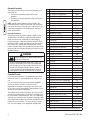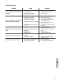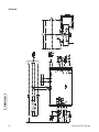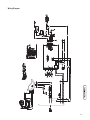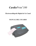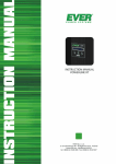
1
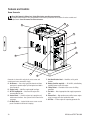
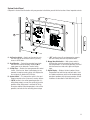
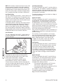
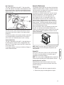
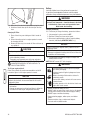
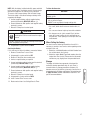
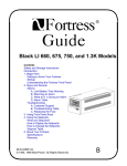
Home Generator Systems
Operator’s Manual
10000 Watt
Home Generator System
Manual No. 207550GS Rev. B (06/23/2008)
Thank you for purchasing this quality-built Briggs & Stratton home generator. We’re pleased that you’ve placed your
confidence in the Briggs & Stratton brand. When operated and maintained according to the instructions in this manual, your
Briggs & Stratton home generator will provide many years of dependable service.
This manual contains safety information to make you aware of the hazards and risks associated with home generator systems
and how to avoid them. This home generator system is designed and intended only for use as an optional home standby
system that provides an alternate source of electric power and to serve loads such as heating, refrigeration systems, and
communication systems that, when stopped during any power outage, could cause discomfort or inconvenience. This product
is not intended for any other purpose and does not qualify for emergency standby as defined by NFPA 70 (NEC).
This home generator requires professional installation before use. Refer to the separate Installation Manual for full
information. Follow the instructions completely. Save these instructions for future reference.
Where to Find Us
You never have to look far to find Briggs & Stratton support and service for your generator. Consult your Yellow Pages.
There are thousands of Briggs & Stratton authorized service dealers worldwide who provide quality service. You can
also contact Briggs & Stratton Customer Service by phone at (800) 743-4115, or use the Service Center Locator at
BRIGGSandSTRATTON.COM, which provides a list of Briggs & Stratton Authorized Dealers.
Date of Purchase
Generator
Model Number
Model Revision
Serial Number
Engine
Model Number
Briggs & Stratton Power Products Group, LLC
900 North Parkway
Jefferson, WI 53549
Copyright © 2008 Briggs & Stratton Power Products Group, LLC.
All rights reserved. No part of this material may be reproduced or
transmitted in any form by any means without the express written
permission of Briggs & Stratton Power Products Group, LLC.
2
BRIGGSandSTRATTON.COM
Table of Contents
Important Safety Instructions. . . . . . . . . . . . . . . . . . . . . . . . 4
Hazard Symbols and Meanings . . . . . . . . . . . . . . . . . . . . . . . . . . . . . . . . . . 4
Installation . . . . . . . . . . . . . . . . . . . . . . . . . . . . . . . . . . . . 7
For the Home Owner:. . . . . . . . . . . . . . . . . . . . . . . . . . . . . . . . . . . . . . . . . . 7
For the Installing Dealer/Contractor: . . . . . . . . . . . . . . . . . . . . . . . . . . . . . . 7
Owner Orientation . . . . . . . . . . . . . . . . . . . . . . . . . . . . . . . . . . . . . . . . . . . . 7
Fuel Factors . . . . . . . . . . . . . . . . . . . . . . . . . . . . . . . . . . . . . . . . . . . . . . . . . 7
Generator Location. . . . . . . . . . . . . . . . . . . . . . . . . . . . . . . . . . . . . . . . . . . . 8
Essential Circuits . . . . . . . . . . . . . . . . . . . . . . . . . . . . . . . . . . . . . . . . . . . . . 8
Delivery Inspection. . . . . . . . . . . . . . . . . . . . . . . . . . . . . . . . . . . . . . . . . . . . 9
Features and Controls. . . . . . . . . . . . . . . . . . . . . . . . . . . . 10
Home Generator. . . . . . . . . . . . . . . . . . . . . . . . . . . . . . . . . . . . . . . . . . . . . 10
System Control Panel. . . . . . . . . . . . . . . . . . . . . . . . . . . . . . . . . . . . . . . . . 11
Access Covers . . . . . . . . . . . . . . . . . . . . . . . . . . . . . . . . . . . . . . . . . . . . . . 12
Operation . . . . . . . . . . . . . . . . . . . . . . . . . . . . . . . . . . . . 12
Important Owner’s Considerations. . . . . . . . . . . . . . . . . . . . . . . . . . . . . . . 12
Automatic Operation . . . . . . . . . . . . . . . . . . . . . . . . . . . . . . . . . . . . . . . . . 12
Setting Exercise Timer . . . . . . . . . . . . . . . . . . . . . . . . . . . . . . . . . . . . . . . . 13
Maintenance . . . . . . . . . . . . . . . . . . . . . . . . . . . . . . . . . . 13
Servicing the System . . . . . . . . . . . . . . . . . . . . . . . . . . . . . . . . . . . . . . . . . 13
Fault Detection System . . . . . . . . . . . . . . . . . . . . . . . . . . . . . . . . . . . . . . . 13
Generator Maintenance . . . . . . . . . . . . . . . . . . . . . . . . . . . . . . . . . . . . . . . 15
Engine Oil. . . . . . . . . . . . . . . . . . . . . . . . . . . . . . . . . . . . . . . . . . . . . . . . . . 15
Battery . . . . . . . . . . . . . . . . . . . . . . . . . . . . . . . . . . . . . . . . . . . . . . . . . . . . 16
When Calling the Factory . . . . . . . . . . . . . . . . . . . . . . . . . . . . . . . . . . . . . . 17
Storage. . . . . . . . . . . . . . . . . . . . . . . . . . . . . . . . . . . . . . . . . . . . . . . . . . . . 17
Troubleshooting. . . . . . . . . . . . . . . . . . . . . . . . . . . . . . . . 19
Schematic . . . . . . . . . . . . . . . . . . . . . . . . . . . . . . . . . . . . . . . . . . . . . . . . . 20
Wiring Diagram . . . . . . . . . . . . . . . . . . . . . . . . . . . . . . . . . . . . . . . . . . . . . 21
Warranty. . . . . . . . . . . . . . . . . . . . . . . . . . . . . . . . . . . . . 22
Product Specifications . . . . . . . . . . . . . . . . . . . . . . . . . . . 24
3
Save These Instructions
Important Safety Instructions
The safety alert symbol ( ) is used with a signal word
(DANGER, CAUTION, WARNING), a pictorial and/or a safety
message to alert you to hazards. DANGER indicates a hazard
which, if not avoided, will result in death or serious injury.
WARNING indicates a hazard which, if not avoided, could
result in death or serious injury. CAUTION indicates a hazard
which, if not avoided, might result in minor or moderate
injury. NOTICE indicates a situation that could result in
equipment damage. Follow safety messages to avoid or
reduce the risk of injury or death.
The manufacturer cannot possibly anticipate every possible
circumstance that might involve a hazard. The warnings in
this manual, and the tags and decals affixed to the unit are,
therefore, not all-inclusive. If you use a procedure, work
method or operating technique that the manufacturer does
not specifically recommend, you must satisfy yourself that
it is safe for you and others. You must also make sure that
the procedure, work method or operating technique that you
choose does not render the generator system unsafe.
NOTE: Your generator is equipped with a spark arrester
muffler. The spark arrester must be maintained in effective
working order by the owner/operator. In the State of
California, a spark arrester is required by law (Section 4442
of the California Public Resources Code). Other states may
have similar laws. Federal laws apply on federal lands.
Hazard Symbols and Meanings
Explosion
Fire
Electrical Shock
Toxic Fumes
Rotating Parts
Hot Surface
WARNING
Storage batteries give off explosive hydrogen
gas during recharging.
Slightest spark will ignite hydrogen and cause
explosion.
Battery electrolyte fluid contains acid and is
extremely caustic.
Contact with battery contents will cause severe
chemical burns.
A battery presents a risk of electrical shock and
high short circuit current.
• DO NOT dispose of battery in a fire.
• DO NOT allow any open flame, spark, heat, or lit cigarette
during and for several minutes after charging a battery.
• DO NOT open or mutilate the battery.
• Wear protective goggles, rubber apron, and rubber
gloves.
• Remove watches, rings, or other metal objects.
• Use tools with insulated handles.
WARNING
Running engine gives off carbon monoxide, an
odorless, colorless, poison gas.
Breathing carbon monoxide can cause
headache, fatigue, dizziness, vomiting,
confusion, seizures, nausea, fainting or death.
• Operate generator ONLY outdoors.
• Install a battery operated carbon monoxide alarm near the
bedrooms.
• Keep exhaust gas from entering a confined area through
windows, doors, ventilation intakes, or other openings.
WARNING
The engine exhaust from this product contains chemicals
known to the State of California to cause cancer, birth
defects, or other reproductive harm.
Auto Start
Explosive Pressure
Chemical Burn
WARNING
Certain components in this product and related
accessories contain chemicals known to the State
of California to cause cancer, birth defects, or other
reproductive harm. Wash hands after handling.
4
BRIGGSandSTRATTON.COM
WARNING
Generator produces hazardous voltage.
Failure to properly ground generator can result
in electrocution.
Failure to isolate generator from power utility
can result in death or injury to electric utility
workers due to backfeed of electrical energy.
• When using generator for backup power, notify utility
company.
• DO NOT touch bare wires or receptacles.
• DO NOT use generator with electrical cords which are
worn, frayed, bare or otherwise damaged.
• DO NOT handle generator or electrical cords while
standing in water, while barefoot, or while hands or feet
are wet.
• If you must work around a unit while it is operating,
stand on an insulated dry surface to reduce shock hazard.
• DO NOT allow unqualified persons or children to operate
or service generator.
• In case of an accident caused by electrical shock,
immediately shut down the source of electrical power and
contact the local authorities. Avoid direct contact with
the victim.
• Despite the safe design of the home generator, operating
this equipment imprudently, neglecting its maintenance
or being careless can cause possible injury or death.
• Remain alert at all times while working on this
equipment. Never work on the equipment when you are
physically or mentally fatigued.
• Before performing any maintenance on the generator,
disconnect the battery cable indicated by a NEGATIVE,
NEG or (-) first. When finished, reconnect that cable last.
• After your home generator is installed, the generator
may crank and start without warning any time there is a
power failure. To prevent possible injury, always set the
generator’s system switch to OFF, remove the service
disconnect from the disconnect box AND remove the
15 Amp fuse BEFORE working on the equipment.
WARNING
Propane and Natural Gas are extremely
flammable and explosive.
Fire or explosion can cause severe burns or
death.
• Install the fuel supply system according to applicable
fuel-gas codes.
• Before placing the home generator into service, the fuel
system lines must be properly purged and leak tested.
• After the generator is installed, you should inspect the
fuel system periodically.
• NO leakage is permitted.
• DO NOT operate engine if smell of fuel is present or other
explosive conditions exist.
• DO NOT smoke around the generator. Wipe up any oil
spills immediately. Ensure that no combustible materials
are left in the generator compartment. Keep the area near
the generator clean and free of debris.
WARNING
Contact with muffler area can result in serious
burns.
Exhaust heat/gases can ignite combustibles or
structures causing a fire.
• DO NOT touch hot parts and AVOID hot exhaust gases.
• Allow equipment to cool before touching.
• DO NOT install the generator closer than 5 feet (1.5m)
from any combustibles or structures with combustible
walls having a fire resistance rating of less than 1 hour.
• Keep at least minimum distances shown in General
Location Guidelines to insure for proper generator
cooling and maintenance clearances.
• Code of Federal Regulation (CFR) Title 36 Parks, Forests,
and Public Property require equipment powered by an
internal combustion engine to have a spark arrester,
maintained in effective working order, complying to
USDA Forest service standard 5100-1C or later revision.
In the State of California a spark arrester is required
under section 4442 of the California Public resources
code. Other states may have similar laws.
5
WARNING
Starter and other rotating parts can entangle
hands, hair, clothing, or accessories.
• NEVER operate generator without protective housing or
covers.
• DO NOT wear loose clothing, jewelry or anything that
may be caught in the starter or other rotating parts.
• Tie up long hair and remove jewelry.
CAUTION
Installing the 15A fuse could cause the engine
to start.
• Observe that the 15 Amp fuse has been removed from
the control panel for shipping.
• DO NOT install this fuse until all plumbing and wiring has
been completed and inspected.
CAUTION
Excessively high operating speeds increase risk of injury
and damage to generator.
Excessively low speeds impose a heavy load.
• DO NOT tamper with governed speed. Generator supplies
correct rated frequency and voltage when running at
governed speed.
• DO NOT modify generator in any way.
NOTICE
NOTICE
Improper treatment of generator can damage it and
shorten its life.
• Use generator only for intended uses.
• If you have questions about intended use, ask dealer or
contact Briggs & Stratton.
• Operate generator only on level surfaces.
• Adequate, unobstructed flow of cooling and ventilating air
is critical to correct generator operation.
• The Oil Fill, Oil Drain and the Control Panel doors must be
installed whenever the unit is running.
• DO NOT expose generator to excessive moisture, dust,
dirt, or corrosive vapors.
• Despite the safe design of the home generator, operating
this equipment imprudently, neglecting its maintenance or
being careless can cause possible injury or death.
• Remain alert at all times while working on this
equipment. NEVER work on the equipment when you are
physically or mentally fatigued.
• DO NOT start engine with air cleaner or air cleaner cover
removed.
• DO NOT insert any objects through cooling slots.
• DO NOT use the generator or any of its parts as a step.
Stepping on the unit can cause stress and break parts.
This may result in dangerous operating conditions from
leaking exhaust gases, fuel leakage, oil leakage, etc.
• If connected devices overheat, turn them off and
disconnect them from generator.
• Shut off generator if:
-electrical output is lost;
-equipment sparks, smokes, or emits flames;
-unit vibrates excessively.
Exceeding generators wattage/amperage capacity can
damage generator and/or electrical devices connected to it.
• See Essential Circuits.
• Start generator and let engine stabilize before connecting
electrical loads.
6
BRIGGSandSTRATTON.COM
Installation
We sincerely appreciate your patronage. For this reason,
Briggs & Stratton has made every effort to provide for a safe,
streamlined and cost-effective installation. Because each
installation is unique, it is impossible to know of and advise
the trade of all conceivable procedures and methods by
which installation might be achieved. Neither could we know
of possible hazards and/or the results of each method or
procedure. For these reasons,
Only current licensed electrical and plumbing contractors
should attempt home generator system installations.
Installations must strictly comply with all applicable
codes, industry standards and regulations.
Your Briggs & Stratton home generator is supplied with this
“Operator’s Manual” and a separate “Installation Manual”.
These are important documents and should be retained by
the owner after the installation has been completed.
For the Home Owner:
To help you make informed choices and communicate
effectively with your installation contractor(s),
Read and understand Owner Orientation in this manual
before contracting or starting your home generator
installation.
To arrange for proper installation, contact the store at which
you purchased your Briggs & Stratton home generator, your
dealer, a licensed electrician or your utility power provider.
The home generator warranty is VOID unless the
system is installed by licensed electrical and plumbing
professionals.
The Emission Control System for this generator is warranted
for standards set by the U.S. Environmental Protection
Agency and by the California Air Resources Board (CARB).
Federal and local codes, appearance, noise levels, fuel types,
and distances are the factors that must be considered when
negotiating with an installation professional. Remember
that as the distance from the existing electrical service and
gaseous fuel supply increases, and the number of 90 degree
bends in the fuel supply increases; equal compensations
in piping and wiring materials must be allowed for. This is
necessary to comply with local codes and overcome electrical
voltage drops and gaseous fuel pressure drops.
The factors mentioned above will have a direct affect on
the overall price of your home generator installation.
NOTE: In some areas you may need to acquire electrical
permits for installing the home generator, building permits
for installing gas lines, and permits for noise allowances.
Your installer should check your local codes AND obtain the
permits before installing the system.
Fuel Factors
An important consideration affecting the entire installation is
the type of fuel used by your home generator. The system
was factory tested and adjusted using either natural gas or
liquid propane (LP vapor). For proper engine function, factors
that are inherent to each of these fuels, your location and
the duration of possible utility interruptions are important
considerations in the following fuel guidelines:
• Use clean, dry fuel, free of moisture or any
particulate material. Using fuels outside the following
recommended values may cause performance
problems.
• In engines set up to run on propane (LP), commercial
grade HD5 propane with a minimum fuel energy of
2500 BTUs/ft3 with maximum propylene content of
5% and butane and heavier gas content of 2.5% and
minimum propane content of 90%.
WARNING
For the Installing Dealer/Contractor:
For most applications, the Installation manual contains all
the information required to properly install and start the
home generator. This Operator’s Manual describes essential
circuit selection, routine operation and owner maintenance
procedures.
If you need more information, call (800) 743-4115, between
8:00 AM and 5:00 PM CT.
Owner Orientation
This section provides home generator owners with the
information necessary to achieve the most satisfactory and
cost effective installation possible.
The illustrations are for typical circumstances and are meant
to familiarize you with the installation options available with
your home generator. A thorough understanding of these
options will provide fundamental control over the cost of
your installation, as well as ensure your final satisfaction and
security.
Propane and Natural Gas are extremely
flammable and explosive.
Fire or explosion can cause severe burns or
death.
• The home generator is equipped with an automatic safety
gas “fuel shut-off” valve.
• DO NOT operate the equipment if the “fuel shut-off” valve
is missing or inoperative.
Power Decrease at High Altitude or High Temperature
Air density is less at high altitudes, resulting in less available
engine power. Specifically, engine power will decrease 3.5%
for each 1,000 feet (300 meters) above sea level and 1% for
each 10° F (5.6°C) above 77°F (25°C). Make sure you and
your installer consider these factors when determining total
generator load.
7
Generator Location
The actual physical location of your home generator has a
direct affect on:
1. The amount of plumbing required to fuel your
generator.
2. The amount of wiring required to control and connect
your generator.
NOTE: Specific location guidelines are discussed in the
Installation Manual. Acquaint yourself with that information
and confer with your installer. Be sure to ask how your site
might affect installation costs and compliance with local
codes and standards.
Generator Clearances
The generator must be installed outdoors. DO NOT install
generator where exhaust gas could accumulate and enter
inside or be drawn into a potentially occupied building.
Ensure exhaust gas is kept away from any windows, doors,
ventilation intakes or other openings that can allow exhaust
gas to collect in a confined area. Prevailing winds and air
currents should be taken into consideration when positioning
generator. See the Installation Manual for full details on safe
generator location.
WARNING
Exhaust heat/gases can ignite combustibles or
structures causing a fire.
• DO NOT install the generator closer than 5 feet (1.5m)
from any combustibles or structures with combustible
walls having a fire resistance rating of less than 1 hour.
• Keep at least minimum distances shown in General
Location Guidelines in Installation Manual to insure for
proper generator cooling and maintenance clearances.
Essential Circuits
As a home generator owner, it is important that you clearly
identify the circuits in your building that are “essential” to
you.
It is also important that your installer understand which
circuits you want to include as “Essential Circuits”.
Depending on the power consumed by these circuits, most
or all of them can be switched to the home generator for the
duration of normal power interruption.
The wattage reference table that follows will assist you with
your decision-making process. It provides the wattage used
by many ordinary household devices. Use it as a guide when
selecting your essential circuits. Review this information with
your installer and ask about any technical considerations that
might affect your installation. This chart serves as a guide
only. For exact wattage use an appropriate wattage meter
Device
Running Watts
Air Conditioner (12,000 Btu)*
1700
Air Conditioner (24,000 Btu)*
3800
Air Conditioner (40,000 Btu)*
6000
Battery Charger (20 Amp)
500
Circular Saw (6-1/2”)
Clothes Dryer (Electric)*
5750
Clothes Dryer (Gas)*
700
Clothes Washer*
1150
Coffee Maker
1750
Compressor (1 HP)*
2000
Compressor (1/2 HP)*
1400
Compressor (3/4 HP)*
1800
Curling Iron
700
Dehumidifier*
650
Electric Blanket
400
Electric Range (per element)
1500
Electric Skillet
1250
Freezer*
700
Furnace Fan (1/2 HP)*
800
Garage Door Opener*
500 to 750
Hair Dryer
1200
Hand Drill
250 to 1100
Iron
1200
Jet Pump*
800
Light Bulb
100
Microwave Oven
Milk Cooler*
1100
Oil Burner on Furnace
300
Oil Fired Space Heater (140,000 Btu)
400
Oil Fired Space Heater (30,000 Btu)
150
Oil Fired Space Heater (85,000 Btu)
225
Radio
Refrigerator
700
Slow Cooker
200
Submersible Pump (1 HP)*
2000
Submersible Pump (1/2 HP)*
1500
Submersible Pump (1-1/2 HP)*
2800
Sump Pump*
800 to 1050
Table Saw (10”)*
1750 to 2000
Television
Toaster
800 to 1000
700 to 1000
50 to 200
200 to 500
1000 to 1650
*Allow three (3) times listed watts for starting device
8
BRIGGSandSTRATTON.COM
Essential Circuit Selection
When selecting the essential circuits that will be switched
to “Standby Power,” it is important that the sum of the
combined circuit loads does not exceed the wattage/
amperage capacity of the generator. To help you with your
selection of essential circuits, please consider the following:
• Add up the total wattage of all electrical devices to be
connected at one time. This total should NOT be greater
than the generator’s wattage capacity.
The rated wattage of lights can be taken from light
bulbs. The rated wattage of tools, appliances and
motors can usually be found on a data plate or decal
affixed to the device.
• If the appliance, tool or motor nameplate does not
list wattage, multiply volts times the ampere rating to
determine watts (Volts x Amps = Watts).
Some electric motors (induction types) require about
three times more watts of power for starting than for
running. This surge lasts for only a few seconds. Be
sure you allow for this high starting wattage when
selecting electrical devices that will be energized by the
home generator:
• Figure the watts required to start the largest motor.
• Add that to the total running watts of all other
connected loads.
This Briggs & Stratton home generator complies with the
following “stationary standby power rating”:
The standby power rating is applicable for supplying
power for the duration of normal power interruption.
No sustained overload capability is available for this
rating.
This rating is applicable to installations served by
a reliable normal utility source. This rating is only
applicable to variable loads with an average load factor
of 80% of the standby rating. The standby rating is
only applicable for optional standby power where the
generator set serves as the backup to the normal utility
source.
Use the wattage reference table provided and mark those
circuits you consider “critical” or “essential”. Make sure you
and your installer consider the system’s altitude above sea
level and the ambient temperature range when determining
total generator load.
IMPORTANT: When using the 100 Amp or 200 Amp transfer
switch with the home generator, you must turn off any non
essential loads. Failure to turn off non essential loads could
overload the generator causing it to shut down.
Some examples of non essential loads are as follows:
• Pool pump
• Hot tub
• Electric hot tub and/or pool heaters
• Central air conditioners
• Electric hot water heaters
• Electric range and/or oven
• Arc welder
• Non essential electric heaters
Delivery Inspection
Carefully inspect the home generator for any damage that
may have occurred during shipment.
IMPORTANT: If loss or damage is noted at time of delivery,
have the person(s) making delivery note all damage on the
freight bill and affix his signature under the consignor’s
memo of loss or damage. If loss or damage is noted after
delivery, separate the damaged materials and contact the
carrier and your installer for claim procedures. Missing or
damaged parts are not warranted.
The home generator is supplied with:
• Home generator
• Pre-attached mounting pad
• One flexible hook-up hose (meets UL 569 and CSA 8.3)
• Installation and Start-up manual
• Operator’s manual
• Installation checklist
• Touch up paint
• Oil drain tray
• Roof hardware bag
• One spare 15A fuse
• 2 Pole connector (for 240V from house)
• 10 Pole connector (for sensing and control wires)
• Remote LED Indicator kit (red LED/plate/screws)
Required Items Supplied by Installer
• Battery
9
Features and Controls
Home Generator
Read this Operator’s Manual and Safety Rules before operating your generator.
Compare the illustrations with your generator to familiarize yourself with the locations of various controls and
adjustments. Save this manual for future reference.
B
A
C
D
E
L
F
G
K
J
H
Generator is shown with roof, plastic access cover and
control panel cover removed for clarity.
A - Air Cleaner — Uses a dry type filter element and foam
precleaner to protect engine by filtering dust and debris
out of intake air.
B - Engine Label — Identifies engine model and type.
C - Oil Fill Cap/Dipstick — Check and fill engine with
recommended oil here.
D - Control Panel — Used for various test, operation and
maintenance functions. See System Control Panel on the
next page.
E - Oil Drain Hose — Located inside access cover on side
panel. Provided to facilitate oil changing.
10
F - Unit Identification Label — Identifies unit by serial
number.
G - Battery (installer supplied) — 12 Volt DC, sealed battery
provides power to start the engine.
H - Lifting Pocket — Provided at each corner for lifting
generator.
J - Fuel Inlet — Attach appropriate fuel supply to generator
here.
K - Exhaust Port — High-performance muffler lowers engine
noise to comply with most residential codes.
L - Oil Filter — Filters engine oil to prolong generator life.
BRIGGSandSTRATTON.COM
System Control Panel
Compare this Control Panel illustration with your generator to familiarize yourself with the location of these important controls:
C
D
E
F
B
A
A - Set Exercise Switch — Used to set the exercise cycle
start time and day-of-the-week. Exercise cycle only
occurs in AUTO mode.
B - Circuit Breaker — Protects the generator from shorts
and other over-current conditions. Must be ON to
supply power to the Automatic Transfer Switch.
C - 15 Amp Fuse — Protects the home generator DC control
circuits. If the fuse has ‘blown’ (melted open) or was
removed, the engine cannot crank or start. Replace the
fuse using only an identical ATO 15A fuse.
D - System Switch — This two-position switch is the most
important control on the system and is used as follows:
• “AUTO” position is the normal operating position. If a
utility power outage is sensed, the system will start the
generator. When utility power is restored, AUTO lets
the engine stabilize internal temperatures, shuts off the
generator, and waits for the next utility power outage.
• “OFF” position turns off running generator, prevents
unit from starting and resets any detected faults.
E - Manual Over-Ride Switch — With system switch in
AUTO position, push the manual over-ride switch to
start the generator. To turn off the generator, push and
hold the manual over-ride switch again until engine
stops.
F - Digital Display — Displays the total number of hours
the generator has been running and fault codes. Used
to schedule maintenance tasks and for troubleshooting
operational problems with the home generator. All fault
conditions are described in Fault Detection System.
11
Access Covers
The home generator is equipped with an enclosure that has a
removable roof and an access cover for the control panel.
To Remove Roof:
Remove the four screws and lift off.
To Remove Access Cover:
1. Remove roof as described above.
2. Remove screw at top of access cover.
3. Pull access cover outward (away) from unit while pulling
cover upward and out of base. cover will come free.
To Install Access Cover and Roof:
1. Guide bottom of access cover into base.
2. Push access cover until it is flush with sides.
3. Replace cover screw.
4. Replace roof and screws.
WARNING
Battery posts, terminals and related accessories contain
lead and lead compounds - chemicals known to the State
of California to cause cancer and reproductive harm.
Wash hands after handling.
15 Amp Fuse
The generator’s 15 Amp fuse was removed at the factory to
prevent the unit from starting during shipping. Your installer
will ensure the fuse is properly installed upon completion of
the installation.
Automatic Operation
Operation
Important Owner’s Considerations
Engine Oil
This engine is shipped from the factory filled with the
recommended oil. Before starting the engine, check oil level
and ensure that engine is serviced as described in the engine
operator’s manual. See Engine Oil in Maintenance.
NOTICE
Any attempt to crank or start the engine before it has been
properly serviced with the recommended oil will result in
equipment failure.
• Refer to Maintenance and engine manual for oil fill
information.
• Damage to equipment resulting from failure to follow this
instruction will void engine and generator warranty.
Battery
The installer must supply and install a sealed, valveregulated, lead-acid rechargeable starting battery. The
starting battery MUST conform to the specifications shown
below in the chart.
Battery Specifications
Volts
12 Volt DC
Amps (MIN)
350 CCA (cold cranking amps)
Type
AGM
Terminal Hardware
M8
Dimensions (MAX):
Width
5.325 inches (135mm)
Length
7.875 inches (200mm)
Height
6.875 inches (175mm)
NOTE: DO NOT use a deep-cycle or automotive type battery.
12
With the battery installed, all wiring to transfer switch and
home generator completed, utility power supplied to the
Automatic Transfer Switch, and the system switch in the
AUTO position, the battery receives a trickle charge while the
engine is not running. The trickle charge cannot be used to
recharge a battery that is completely discharged.
To select automatic operation, do the following:
1. Set the service disconnect or main distribution panel
circuit breaker that sends utility voltage to the transfer
switch to ON.
2. Set the generator’s main circuit breaker to its ON position.
3. Set the system switch to AUTO.
CAUTION
With the system switch set to AUTO, the engine
may crank and start at any time without warning.
Such automatic starting normally occurs when
utility source voltage drops below a preset level
or during the normal exercise cycle.
• To prevent possible injury that may be caused by such
sudden starts, always set the system switch to OFF.
• Remove the 15 Amp fuse before working on or around
the generator or transfer switch.
Checking Automatic Operation
To check the system for proper automatic operation, proceed
as follows:
1. Turn OFF the service disconnect or main distribution
panel circuit breaker sending power to the automatic
transfer switch.
The engine will crank and start when the utility voltage drops
out and the sensor has timed out. Let the system go through
its entire automatic operation sequence.
2. With the generator output supplying its loads, turn ON
the service disconnect or main distribution panel circuit
breaker that supplies utility power to the Automatic
Transfer Switch.
3. The automatic transfer switch will transfer loads back to
the utility power after 5 minute minimum run time and
utility is restored.
BRIGGSandSTRATTON.COM
4. The generator will run for an additional one minute for
engine cool down, then shut down.
NOTE: If utility is restored and generator does not shut down
after 10 minutes, set system switch to OFF and contact your
installer or local service center.
This completes the test procedures for automatic operation.
The home generator will now start automatically when utility
power is lost and will supply power to the transfer switch.
Setting Exercise Timer
The home generator is equipped with an exercise timer that
will start and exercise the system once every seven days.
During this exercise period, the unit runs for approximately
20 minutes and then shuts down. Electrical load transfer
DOES NOT occur during the exercise cycle (unless a utility
power outage occurs).
A switch on the control panel is labeled “Set Exercise” (see
System Control Panel). The specific day and the specific
time of day this switch is pressed is programmed into the
control board memory. This date and time is then used
to automatically initiate the system exercise cycle. The
“SET EXERCISE” legend on the control panel will flash until
the set exercise cycle is set.
To perform the Set Exercise procedure:
1. Choose the day and time you want your home generator
to exercise.
2. On that day and time, press and hold down the
“Set Exercise” switch for three seconds.
NOTE: “SET EXERCISE” will flash until the switch is pressed
for three seconds, then “SET EXERCISE” will illuminate for
5 seconds, and finally turn off.
3. The unit will then start and run it’s 20 minute exercise
cycle.
For example, if you press the “Set Exercise” button on
Sunday morning at 10:00 AM, the unit will run an immediate
exercise cycle and then the following Sunday at 10:00 AM
(+/- 1/2 hour).
NOTE: “Set Exercise” will only work if the unit is in the
Automatic mode and this exact procedure is followed. The
exerciser will need to be re-set if the 15 Amp fuse is removed
or changed, or if the 12 Volt DC battery is disconnected.
If you want to change the day and time the unit exercises,
simply perform the “Set Exercise” procedure at the exact
weekday and time you want it to take place.
Maintenance
Servicing the System
To service system:
1. Set the system switch to OFF.
2. Set the generator’s main circuit breaker to its OFF
position.
3. Utility voltage is present. Disconnect power before
servicing by removing the two 2 Amp fuses from the
transfer switch.
Fault Detection System
The generator may have to run for long periods of time with
no operator present. For that reason, the system is equipped
with sensors that automatically shut down the generator
in the event of potentially damaging conditions, such as
low oil pressure, high temperature, over speed, and other
conditions.
The generator’s control panel has a digital display that shows
fault codes, like “FC_1”. The table below lists the detected
fault, the fault code as displayed on the control panel, and
the number of blinks seen on the remote LED indicator.
Fault Description
Fault Codes
LED Flashes
Low battery voltage
FC_1
1
Low oil pressure
FC_2
2
Low voltage
FC_3
3
Engine fails to start
FC_4
4
Low frequency
FC_5
5
Engine overspeed
FC_6
6
High temperature
FC_7
7
Transfer switch fault
FC_8
8
The remote LED indicator is installed at a convenient inside
location. The LED will remain lit when the generator is in
AUTO. The LED will turn on and off in a series of blinks that
correspond to the fault detected in your home generator. The
blink pattern is repeated with a brief pause between each
series of blinks.
Reset Fault Detection System
The operator must reset the fault detection system each time
it activates. To do so, place the system switch in the OFF
position for 5 seconds or more. Remedy the fault condition,
then return the home generator to service by placing the
system switch in the AUTO position.
A description of each fault and suggested remedies are as
follows:
WARNING
Battery posts, terminals and related accessories contain
lead and lead compounds, chemicals known to the State
of California to cause cancer and reproductive harm.
Wash hands after handling.
No LED - Discharged Battery
If there is a detected fault condition but the LED is not
blinking, this is because the battery is completely discharged.
To remedy the problem, remove the 15 Amp fuse and
disconnect the battery from the generator. Take the battery
to a local battery store for analysis. Replace ONLY with same
type battery as described in Battery in Operation. Replace
the battery after it has been fully recharged, connecting the
NEGATIVE cable last. Then install the 15 Amp fuse in the
control panel.
13
NOTE: With the battery installed, all wiring to transfer switch
and home generator completed, utility power supplied to
the Automatic Transfer Switch, and the unit in AUTO mode,
the battery receives a trickle charge while the engine is not
running. The trickle charge is not able to recharge a battery
that is completely discharged. See Battery in Maintenance.
Low Battery Voltage
This fault is indicated by fault code FC_1 and one blink on the
LED indicator. This condition occurs if the generator cannot
start because the starting battery output power is below that
needed to crank the engine. Causes for this problem may be
a faulty battery or battery charge circuit.
To remedy the problem, contact your local service center to
check the battery charge output. Remove the 15 Amp fuse
and disconnect the battery from the generator. Take the
battery to a local battery store for analysis. Replace ONLY
with same type battery as described in Battery in Operation.
Replace the battery after it has been fully recharged, connecting
the NEGATIVE cable last. Then install the 15 Amp fuse.
Low Oil Pressure
This fault is indicated by fault code FC_2 and two blinks on
the remote LED indicator. The unit is equipped with an oil
pressure switch (A).
A
The oil pressure switch uses normally closed contacts that
are held open by engine oil pressure during operation.
Should oil pressure drop below the 8 psi range, switch
contacts close and the engine is shut down.
To remedy the low oil pressure condition, add the
recommended oil to the FULL mark on the dipstick.
If the low oil pressure condition still exists, the engine will
start, then shut down after about 20 seconds. The fault code
will appear and the LED will flash. In this case, contact a
Briggs & Stratton Authorized Dealer.
14
Low Voltage (Generator)
This fault is indicated by fault code FC_3 and three blinks on
the LED indicator. This condition is caused by a restriction in
the fuel flow, a broken or disconnected signal lead, a failed
alternator winding, the control panel circuit breaker is open,
or the generator is overloaded.
To remedy the problem, contact your installer or a Briggs &
Stratton Authorized Dealer.
Engine Fail To Start
This fault is indicated by fault code FC_4 and four blinks on
the LED indicator. This feature prevents the generator from
damaging itself if it continually attempts to start in spite
of another problem, such as no fuel supply. Each time the
system is directed to start, the unit will crank for 10 seconds,
pause for 10 seconds, and repeat. If the system does not
begin producing electricity after approximately 2 minutes, the
unit will stop cranking and the LED will blink.
Check to make sure the generator’s main circuit breaker is in
the ON position in order for the sensing leads to verify that
the unit is running.
The most likely cause of this problem is no fuel supply.
Check the inside and outside fuel shut off valves to ensure
they are fully open. Other causes could be failed spark
plug(s), failed engine ignition, or the engine air filter
is clogged. You may need to contact your installer for
assistance if you can’t remedy these problems.
Low Frequency
This fault is indicated by fault code FC_5 and five blinks on
the LED indicator. This feature protects devices connected
to the transfer switch by shutting the generator down
if the engine runs slower than 55 Hz for three seconds.
This condition is caused by a failed engine governor or by
excessive loads on the generator. To remedy the problem,
contact your installer or a Briggs & Stratton Authorized
Dealer.
Engine Overspeed
This fault is indicated by fault code FC_6 and six blinks on
the LED indicator. This feature protects devices connected
to the transfer switch by shutting the generator down if
the engine happens to run faster than the preset limit. The
overspeed fault is detected as follows:
• If the generator output frequency is 65-70 Hz, after
three seconds, the generator will shut down.
• If the generator output frequency is greater than 70 Hz,
the generator will shut down immediately.
This condition is caused by a failed engine governor.
To remedy the problem, contact your installer or a
Briggs & Stratton Authorized Dealer.
BRIGGSandSTRATTON.COM
High Temperature
This fault is indicated by fault code FC_7 and seven blinks
on the LED indicator. The contacts of the temperature switch
(A) are normally open. If the engine oil temperature exceeds
approximately 148.9°C (300°F), the fault is detected and the
engine shuts down.
A
Common causes for this condition include running the
unit with all access covers removed, obstructed air inlet or
exhaust port, low oil level, or debris in the engine cylinder
cooling fins.
To resolve the problem, let the engine cool down and remove
any accumulated debris and obstructions. Ensure that the
access covers are installed whenever the unit is running.
Transfer Switch Fault
This fault is indicated by fault code FC_8 and eight blinks on
the LED indicator (if transfer switch is equipped with fault
detection). The most likely cause of this fault is a blown fuse
in the transfer switch.
To remedy the problem, contact your installer or a Briggs &
Stratton Authorized Dealer.
Generator Maintenance
The generator warranty does not cover items that have been
subjected to operator abuse or neglect. To receive full value
from the warranty, the operator must maintain the system as
instructed in the engine operator’s manual.
All adjustments should be made at least once each season.
Follow the requirements in the engine operator’s manual.
Generator maintenance consists of keeping the unit
clean. Operate the unit in an environment where it will
not be exposed to excessive dust, dirt, moisture or any
corrosive vapors. Cooling air louvers on the enclosure
must not become clogged with snow, leaves, or any other
foreign material. To prevent generator damage caused by
overheating, keep the enclosure cooling inlets and outlets
clean and unobstructed at all times.
Check the cleanliness of the unit frequently and clean when
dust, dirt, oil, moisture or other foreign substances are
visible on its exterior/interior surface. Inspect the air inlet and
outlet openings inside and outside the enclosure to ensure
air flow is not blocked.
NOTE: DO NOT use direct spray from a garden hose to clean
generator. Water can enter the engine and generator and
cause problems.
Engine Oil
The system is filled with synthetic oil (API SJ/CF 5W-30W).
This allows for system operation in the widest range of
temperature and climate conditions.
NOTE: The use of synthetic oil does not alter the required oil
change intervals described in the engine operator’s manual.
Changing Engine Oil and Filter
Remove the two screws from each plastic access cover
and remove both access covers from the two sides of the
generator enclosure.
Changing Oil
1. Place the oil drain tube into an approved container.
2. Remove brass plug from tube opposite of engine.
15
Battery
Servicing of batteries are to be performed or supervised
by personnel knowledgeable of batteries and the required
precautions. Keep unauthorized personnel away from batteries.
WARNING
3. When the oil has drained, replace brass plug into tube.
4. Slide the oil drain tube up into the clamp on the fuel
hose.
Changing Oil Filter
1. Place oil drain tray over tubing and slide it under oil
filter.
2. Follow instructions given in engine operator’s manual
for changing oil filter.
3. Remove oil drain tray from under oil filter and clean up
any spilled oil.
CAUTION
Avoid prolonged or repeated skin contact with used motor
oil.
• Used motor oil has been shown to cause skin cancer in
certain laboratory animals.
• Thoroughly wash exposed areas with soap and water.
KEEP OUT OF REACH OF CHILDREN. DON’T POLLUTE.
CONSERVE RESOURCES. RETURN USED OIL TO
COLLECTION CENTERS.
To fill your engine with oil:
Follow the synthetic oil grade recommendation and oil fill
instructions given in the engine operator’s manual.
NOTICE
Any attempt to crank or start the engine before it has been
properly serviced with the recommended oil will result in
equipment failure.
• Refer to Maintenance and engine manual for oil fill
information.
• Damage to equipment resulting from failure to follow this
instruction will void engine and generator warranty.
16
Battery posts, terminals and related accessories contain
lead and lead compounds - chemicals known to the State
of California to cause cancer and reproductive harm.
Wash hands after handling.
Charging the Battery
If it is necessary to charge the battery, proceed as follows:
1. Set generator’s system switch to OFF.
2. Remove 15 Amp fuse from control panel.
3. Disconnect negative battery cable to negative battery
terminal (indicated by NEGATIVE, NEG, or (-).
NOTICE
Failure to disconnect negative battery cable will result in
equipment failure.
• DO NOT attempt to jump start the battery.
• Damage to equipment resulting from failure to follow this
instruction will void warranty.
4. Charge battery with battery charger at 2 Amps until
battery holds 12 Volts.
NOTE: DO NOT exceed 13.7 Volts charging.
WARNING
Storage batteries give off explosive hydrogen
gas during recharging.
Slightest spark will ignite hydrogen and cause
explosion.
Battery electrolyte fluid contains acid and is
extremely caustic.
Contact with battery contents will cause severe
chemical burns.
A battery presents a risk of electrical shock and
high short circuit current.
• DO NOT dispose of battery in a fire.
• DO NOT allow any open flame, spark, heat, or lit cigarette
during and for several minutes after charging a battery.
• DO NOT open or mutilate the battery.
• Wear protective goggles, rubber apron, and rubber
gloves.
• Remove watches, rings, or other metal objects.
• Use tools with insulated handles.
BRIGGSandSTRATTON.COM
NOTE: With the battery installed and utility power available
to the transfer switch, the battery receives a trickle charge
whenever the engine is not running. It may take up to
72 hours to fully charge a battery with the trickle charge.
The trickle charge is not able to recharge a battery that is
completely discharged.
5. Connect negative battery cable to negative battery
terminal (indicated by NEGATIVE, NEG, or (-)).
6. Ensure hardware on both positive and negative battery
terminals is secure.
7. Reinstall 15 Amp fuse in control panel.
CAUTION
Installing the 15A fuse could cause the engine
to start.
• DO NOT install this fuse until all plumbing and wiring has
been completed and inspected.
8. Set generator’s system switch to AUTO.
Servicing the Battery
If it is necessary to service the battery, proceed as follows:
1. Remove “Control Panel” access cover.
2. Set generator’s system switch to OFF.
3. Remove 15 Amp fuse from control panel.
4. Service or replace battery as required.
5. Connect red battery cable to battery positive terminal
(indicated by POSITIVE, POS, or (+)).
6. Connect negative battery cable to negative battery
terminal (indicated by NEGATIVE, NEG, or (-).
7. Ensure hardware on both positive and negative battery
terminals is secure.
8. Reinstall 15 Amp fuse in control panel.
9. Set generator’s system switch to AUTO.
10. Install “Control Panel” access cover.
11. Reset exercise timer. See Setting Exercise Timer.
To Clean the Generator
NOTICE
Improper treatment of generator can damage it and
shorten its life.
• DO NOT expose generator to excessive moisture, dust,
dirt, or corrosive vapors.
• DO NOT insert any objects through cooling slots.
• Use a damp cloth to wipe exterior surfaces clean.
• Use a soft, bristle brush to loosen caked on dirt, oil,
etc.
• Use a vacuum cleaner to pick up loose dirt and debris.
• Use low pressure air (not to exceed 25 psi) to blow
away dirt. Inspect cooling air slots and openings on
the generator. These openings must be kept clean and
unobstructed.
When Calling the Factory
You must have the following information at hand if it is
necessary to contact a local service center regarding service
or repair of this unit:
1. Obtain the unit Model Number and Serial Number from
the unit data decal. See Controls.
2. Obtain the engine Model/Type/Code numbers from the
engine label. See Controls. Please note that the model
number may vary slightly from that presented herein.
Storage
The Briggs & Stratton home generator is designed for
continuous backup operational duty. As such, there is
no need to take any storage precautions. However, if it
becomes necessary to take the system out of service for an
extended period, call Briggs and Stratton Technical Services
at (800) 743-4115, between 8:00 AM and 5:00 PM CT for
specific recommendations.
17
Reserved
18
BRIGGSandSTRATTON.COM
Troubleshooting
Problem
Cause
Correction
1.
2.
3.
Circuit breaker open or defective.
Fault in generator.
Poor wiring connections or
defective transfer switch.
1.
2.
3.
Reset or replace circuit breaker.
Contact local service facility.
Check and repair.
1.
2.
3.
Engine runs good at no-load but “bogs 4.
down” when loads are connected.
5.
Short circuit in a connected load.
Generator is overloaded.
Shorted generator circuit.
Fuel Pressure is incorrect.
1.
2.
3.
4.
Disconnect shorted electrical load.
See Essential Circuits.
Contact local service facility.
See Gaseous Fuel System in the
Installation Manual.
See Gaseous Fuel System in the
Installation Manual.
Remove kink in fuel line. Replace if
necessary.
Install (new) 15 Amp fuse. See
System Control Panel.
Open fuel valve(s); check propane
tank.
Replace battery.
Clean or replace air filter.
Check fuel valves, fill propane tank.
Engine is running, but no AC output is
available.
6.
Kinked fuel line between regulator
and engine.
6.
1.
15 Amp fuse missing or blown.
1.
2.
2.
Fuel supply turned off, restricted or
depleted.
Failed battery.
Clogged air filter.
Fuel supply turned off, restricted or
depleted.
Fault indicator blinking.
2.
Count blinks and refer to Fault
Detection System.
1.
2.
Generator circuit breaker is open.
Transfer switch problems.
1.
2.
Reset circuit breaker.
See the transfer switch manual.
Engine will not start; or starts and runs 2.
rough.
3.
4.
1.
Engine shuts down during operation.
Loss of power on essential circuits.
Natural gas fuel mixture is incorrect. 5.
3.
4.
1.
19
Schematic
20
BRIGGSandSTRATTON.COM
Wiring Diagram
21
#3*((4453"550/108&3130%6$54(3061--$L8)0.&(&/&3"50308/&38"33"/5:10-*$:
Effective March 1, 2008. Replaces all undated Warranties and all Warranties dated before March 1, 2008
-*.*5&%8"33"/5:
Briggs & Stratton Power Products Group, LLC will repair or replace, free of charge, any part(s) of the equipment that is defective in material or
workmanship or both. Transportation charges on product submitted for repair or replacement under this warranty must be borne by purchaser. This
warranty is effective for the time periods and subject to the conditions stated below. For warranty service, find the nearest Authorized Service Dealer in
our dealer locator map at BRIGGSandSTRATTON.COM.
THERE IS NO OTHER EXPRESS WARRANTY. IMPLIED WARRANTIES, INCLUDING THOSE OF MERCHANTABILITY AND FITNESS FOR A PARTICULAR
PURPOSE, ARE LIMITED TO ONE YEAR FROM PURCHASE, OR TO THE EXTENT PERMITTED BY LAW. ANY AND ALL IMPLIED WARRANTIES ARE
EXCLUDED. LIABILITY FOR INCIDENTAL OR CONSEQUENTIAL DAMAGES ARE EXCLUDED TO THE EXTENT EXCLUSION IS PERMITTED BY LAW. Some
states or countries do not allow limitations on how long an implied warranty lasts, and some states or countries do not allow the exclusion or limitation
of incidental or consequential damages, so the above limitation and exclusion may not apply to you. This warranty gives you specific legal rights and
you may also have other rights which vary from state to state or country to country.
8"33"/5:1&3*0%
$POTVNFS6TF
ZFBSTPSIPVSTXIJDIFWFSDPNFTGJSTU
$PNNFSDJBM6TF
/POF
The warranty period begins on the date of purchase by the first retail consumer or commercial end user, and continues for the period of time stated in the
table above. “Consumer use” means personal residential household use by a retail consumer. “Commercial use” means all other uses, including use for
commercial, income producing or rental purposes. Once equipment has experienced commercial use, it shall thereafter be considered as commercial use for
purposes of this warranty.
NO WARRANTY REGISTRATION IS NECESSARY TO OBTAIN WARRANTY ON BRIGGS & STRATTON PRODUCTS. SAVE YOUR PROOF OF PURCHASE
RECEIPT. IF YOU DO NOT PROVIDE PROOF OF THE INITIAL PURCHASE DATE AT THE TIME WARRANTY SERVICE IS REQUESTED, THE MANUFACTURING
DATE OF THE PRODUCT WILL BE USED TO DETERMINE THE WARRANTY PERIOD.
"#065:0638"33"/5:
We welcome warranty repair and apologize to you for being inconvenienced. Any Authorized Service Dealer may perform warranty repairs. Most warranty
repairs are handled routinely, but sometimes requests for warranty service may not be appropriate. For example, warranty service would not apply if
equipment damage occurred because of misuse, lack of routine maintenance, shipping, handling, warehousing or improper installation. Similarly, the
warranty is void if the manufacturing date or the serial number on the equipment has been removed or the equipment has been altered or modified. During
the warranty period, the Authorized Service Dealer, at its option, will repair or replace any part that, upon examination, is found to be defective under normal
use and service. This warranty will not cover the following repairs and equipment:
•
Normal Wear: Outdoor Power Equipment and engines, like all mechanical devices, needs periodic parts and service to perform well. This warranty
does not cover repair when normal use has exhausted the life of a part or the equipment.
•
Installation and Maintenance: This warranty does not apply to equipment or parts that have been subjected to improper or unauthorized installation or
alteration and modification, misuse, negligence, accident, overloading, overspeeding, improper maintenance, repair or storage so as, in our judgment,
to adversely affect its performance and reliability. This warranty also does not cover normal maintenance such as adjustments, fuel system cleaning
and obstruction (due to chemical, dirt, carbon, lime, and so forth).
•
Other Exclusions: This warranty excludes starting batteries and wear items such as oil gauges, o-rings, filters, fuses, or spark plugs, etc., or damage
or malfunctions resulting from accidents, abuse, modifications, alterations, or improper servicing or freezing or chemical deterioration. Accessory parts
are excluded from the product warranty. This warranty excludes failures due to acts of God and other force majeure events beyond the manufacturers
control. Also excluded is used, reconditioned, and demonstration equipment; equipment used for prime power in place of utility power and equipment
used in life support applications. 207581E, Rev. -. 6/3/2008
#3*((4453"550/108&3130%6$54(3061--$
+&''&340/8*64"
22
BRIGGSandSTRATTON.COM
Reserved
23
Home Generator Systems
Product Specifications
Rated Maximum Load Current:
at 120 Volts . . . . . . . . . . . . . . . . . . . . . . . . . . . 83.33 Amps
at 240 Volts . . . . . . . . . . . . . . . . . . . . . . . . . . . 41.66 Amps
Rated AC Voltage . . . . . . . . . . . . . . . . . . . . . . .120/240 Volts
Phase . . . . . . . . . . . . . . . . . . . . . . . . . . . . . . . . .Single phase
Rated Frequency . . . . . . . . . . . . . . . . . . . . . . . . . . . . 60 Hertz
Normal Operating Range . . -20°F (-28.8°C) to 104°F (40°C)
Output Sound Level . 70 dB(A) at 23 ft. (7 m) at normal load
This generator is rated in accordance with UL (Underwriters Laboratories) 2200 (stationary engine generator assemblies) and
CSA (Canadian Standards Association) standard C22.2 No. 100-04 (motors and generators).
Briggs & Stratton Power Products Group, LLC
900 N. Parkway
Jefferson, Wisconsin, 53549 U.S.A.
24
(800) 743-4115
BRIGGSandSTRATTON.COM