1
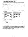
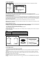
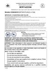
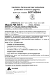
User Instructions
Built-in gas cooktops
BERTAZZONI
DIMENSIONS: 36’’ (915 mm)(W) x 253/16’’ (640 mm)(D)
Models C36500X (Z36500X)
Models C36600X (Z36600X)
[C3W0..U4X(2 or 5)A]
[C3Y0..U4X(2 or 5)A]
IMPORTANT - PLEASE READ AND FOLLOW
-Before beginning installation, please read these instructions completely and carefully.
-Do not remove permanently affixed labels, warnings, or plates from the product. This may void the warranty. -Please observe all local
and national codes and ordinances.
-Please ensure that this product is properly grounded.
-The installer should leave these instructions with the consumer who should retain for local inspector's use and for
future reference.
-The electrical plug should always be accessible.
Installation must conform with local codes or in the absence of codes, the National Fuel Gas Code ANSIZ223.1-latest edition. Electrical
installation must be in accordance with the National Electrical Code, ANIS/NFPA70 - latest edition and/or local codes. IN CANADA:
Installation must be in accordance with the current CAN/CGA-B149.1 National Gas Installation Code or CAN/CGA-B 149.2, Propane
Installation Code and/or local codes. Electrical installation must be in accordance with the current CSA C22.1 Canadian Electrical
Codes Part 1 and/or local codes.
Installation of any gas-fired equipment should be made by a licensed plumber. A manual gas shut-off valve must be installed in the gas
supply line ahead of the oven in the gas flow for safety and ease of service.
In Massachusetts: All gas products must be installed by a "Massachusetts" licensed plumber or gasfitter. A "T" handle type manual
gas valve must be installed in the gas supply line to this appliance.
IMPORTANT: SAVE FOR LOCAL ELECTRICAL INSPECTOR’S USE.
READ AND SAVE THESE INSTRUCTIONS FOR FUTURE REFERENCE.
OBSERVE ALL GOVERNING CODES AND ORDINANCES.
WARNING: If the information in this manual is not followed exactly, a
fire or explosion may result causing property damage, personal injury
or death.
Do not store or use gasoline or other flammable vapors and liquids in
the vicinity of this or any other appliance.
WHAT TO DO IF YOU SMELL GAS
- Do not light any appliance.
- Do not touch any electrical switch.
- Do not use any phone in your building.
- Immediately call your gas supplier from a neighbor’s phone. Follow
the gas supplier’s instructions.
- If you cannot reach your gas suppliers, call the fire department.
Installation and service must be performed by a qualified installer,
service agency or the gas supplier.
310200
SERVICE & MAINTENANCE INSTRUCTIONS
Service and maintenance only to be carried out by an authorised person
To replace parts such as burners, valves and electric components, the appliance must be open removing the worktop.
Note: if the valves must be replaced, first disassemble the ignitions switches wires.
It is recommended to replace the valve gaskets each time the valve is replaced, thus ensuring a perfect seal between the
body and the gas train.
WARNING: After first installation of the appliance or after any service intervention concerning main gas parts of
the appliance, make the leak test using water with soap on the gas connections in order to verify the correct
installation. Do not use fire for gas leak testing.
USER MANUAL
DESCRIPTIONS
DESCRIPTIVE CAPTION FOR HOB
1. Small Burner
2. Medium burner
3. Rapid burner
4. Dual burner
DESCRIPTION OF HOBS
Model C36500X (Z36 5 00 X) [M3W0..U4X(2 or 5)A]Fig. A
Model C36600X (Z36 6 00 X) [M3Y0..U4X(2 or 5)A]Fig. B
Fig. A
Fig. B
CONTROL PANEL DESCRIPTION
On the control panel, small symbols show the function of each knob or key. Here as follows are the several controls that
a cooker can have:
shows the disposition of burners on the worktop, the full dot identifies the burner in object (in
the symbol
this case the front burner on the right).
WARNINGS:
Keeping appliance area clear and free from combustible materials, gasoline and other flammable vapors and
liquid.
Do not store dangerous or flammable material in the cabinet areas above appliance; store them in a safe place
in order to avoid potential hazards.
For safe use of appliance, do not use it for space heating.
Do not use aerosol sprays in the vicinity of this appliance while it is in operation
2
USING BURNERS
A diagram is etched on the control panel above each knob which indicates which burner corresponds to that knob.
Manual ignition:
Manual ignition is always possible even when the power is cut off or in the event of prolonged power failure.
Turn the knob that corresponds to the burner selected counterclockwise to the MAXIMUM position at the etched star
(large flame) and place a lit match up to the burner.
Automatic electric ignition:
Turn the knob that corresponds to the burner selected anticlockwise direction to the MAXIMUM position at the etched
star (large flame) and then press the knob down to activate the spark ignition. Once ignited, keep pressing the knob for
about 10 seconds to allow the flame to heat the thermocouple. If the burner does not remain alight after releasing the
knob repeat the above procedure,
Note: It is recommended not to try to ignite the burner if the relative flame cap is not in the correct position
Note: Dual burner is composed by two burner (inside and outside); each one operates under the relative gas valve
indipendently from the other one.
Tips for using burners correctly:
WARNING: During use of each gas burner(s) adjust the burner flame size properly so it does not extend beyond
the edge of the cooking utensil. This is an instruction based on safety considerations
- Use suitable pots for each burner (see Fig. and Table )
- When the liquid is boiling, turn down the knob to the MINIMUM position.
- Always use pots with a cover.
Correct flame aspect: verify that aspect flame of the worktop burners be completely blue and with an aspect as
indicated in figure(flame)
Table
Burner
Small
Medium
Large
Dual burner
Recommended pan diameters inches (mm)
35½”-551/8”(90 – 140)
551/8”- 1023/8”(140 – 260)
707/8”- 1023/8” (180 – 260)
862/3”-1023/8” (220 – 260)
WARNING: check the position of the burner caps before operation.
Correct usage of pans:
- Dry the bottom of the pan before placing it on the hotplate.
- Use pots with a flat, thick bottom, except for wok cooking.
- When using the burners, ensure that the handles of the pans are correctly positioned. Keep children away from the
appliance.
- When cooking foods with oil and fat, which are very flammable, the user should not leave the appliance unattended.
WOK PAN: To use the wok pan, please utilize a suitable wok adaptor grid; wok pan external diameter shall not be less
than 10” (25cm) and not more than 16”(40cm).
WARNING: If the power is cut off, the burners can be lit with matches.
The burners equipped with a safety thermocouple can only be lit when the knob is in the MAXIMUM position (large flame
etching).
3
CLEANING THE APPLIANCE:
Never use abrasive cleaners
Before cleaning the appliance it should be disconnected from the power supply.
Cleaning the work surface: periodically clean the burner heads, the cast iron pan supports and the burner caps using
warm water.
Any spillage must always be removed as soon as possible using a rag.
If it become difficult to open or close a valve, do not force it, but immediately request the assistance of the
technical service personnel.
Cleaning the enamelled parts: Enamelled parts should be cleaned frequently with soapy water. Never use abrasive
powder. Do not leave acidi or alkaline substances on the enamelled parts (such as vinegar, lemon juice, salt, tomato
sauce, etc.) and do not wash the enamelled parts while they are still hot.
Cleaning the stainless steel parts: Clean the parts with soapy water and dry them with a soft cloth. The shine is
maintained by periodically using specific stainless steel cream cleaner. Never use abrasive powders. Use specific
stainless steel cream cleaner to eliminate the glue remains afther the elimination of the blue plastic protection film on the
worktop after installation.
Cleaning the burner caps: Lift the burner caps from the burner heads and wash them in soapy water and dry
thoroughly. Before replacement on the burner head ensure that the holes are not clogged.
ATTENTION: for further details about cleaning of the appliance, please contact your applliance retailer.
AFTER SALE SERVICE:
Please note here below details for after save service.
Refer to warranty certificate for warranty condiftions
Dealer /Importer:
Name, address, phone
SERVICE CENTERS
Name
Phone
MANUFACTURER:
BERTAZZONI SPA
VIA PALAZZINA, 8 – 42016 – GUASTALLA (REGGIO E.) ITALY
Tel. 0522/226411 – telefax 0522/226440 – http://www.bertazzoni-italia.com
4