1
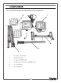
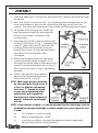
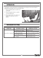
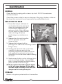
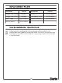
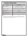
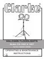
HALOGEN FLOODLIGHTS
Models CHL1260C & 1260T
Part Nos: 5460600 & 5460595
OPERATING & MAINTENANCE
INSTRUCTIONS
GC0610
INTRODUCTION
Thank you for purchasing this CLARKE Halogen Floodlight.
Before attempting to operate the lamp, it is essential that you read this
manual thoroughly and carefully follow all instructions given. In doing so you
will ensure the safety of yourself and that of others around you, and you can
also look forward to the lamp giving you long and satisfactory service.
GUARANTEE
This CLARKE product is guaranteed against faulty manufacture for a period of
12 months from the date of purchase. Please keep your receipt as proof of
purchase.
This guarantee is invalid if the product is found to have been abused or
tampered with in any way, or not used for the purpose for which it was
intended.
Faulty goods should be returned to their place of purchase, no product can
be returned to us without prior permission.
This guarantee does not effect your statutory rights.
2
GENERAL SAFETY WARNINGS
1. Please keep these instructions in a safe place for future reference.
2. Never carry out any alterations or modifications to this product.
3. Keep children and bystanders away from the work area.
4. Although the lamp may be used outdoors, do not leave it exposed to the
elements. Never wash the lamp in water.
5. Never work in damp area without adequate insulation against electric
shock. Avoid moving the lamp with wet hands or when standing on a wet
or damp surface.
6. Check for damage before using. Inspect the power cable and plug for
damage and ensure that no connections are loose. Do not use this unit if it
has a broken lens, casing or damaged supply cable. Any damage should
be properly repaired or the part replaced.
7. Do not use adaptor plugs with earthed (grounded) appliances. Correct
plugs and outlets will reduce the risk of electric shock.
8. Position the power cable so that it cannot be inadvertently pulled or
pinched and where it does not cause a trip hazard.
9. Disconnect from the mains supply and allow the lamp to cool down
before moving or performing any maintenance.
10. Disconnect from the power supply when not in use.
11. Use an external weatherproof socket when using the lamp outdoors.
12. Never abuse the mains cable or wrench the cable to disconnect it from
the socket. Keep the cable away from sharp edges/hot surfaces.
13. Never cover the lamps.
14. Never use this lamp in hazardous locations, such as flammable or
explosive environments.
15. Never look directly into the lamp when switched on as this can damage
the eyes.
16. Never install this unit within 2 metres of combustible material and ensure
that the front and the top of the halogen lamp is at least 1 metre away
from any flat or fixed surface. The lamp housing can exceed temperatures
of 90°C.
17. Store this product in a dry, secure place out of reach of children.
Your CLARKE lamp has been designed to give long and trouble free service.
If, however, having followed the instructions in this booklet carefully, you
encounter problems, take the unit to your local CLARKE dealer.
3
ELECTRICAL CONNECTIONS
WARNING! Read these electrical safety instructions thoroughly
before connecting the product to the mains supply.
Before switching the product on, make sure that the voltage of your
electricity supply is the same as that indicated on the rating plate. This
product is designed to operate on 230VAC 50Hz. Do not connect it to any
other power source.
This product may be fitted with a non-rewireable plug. If it is necessary to
change the fuse in the plug, the fuse cover must be refitted. If the fuse cover
becomes lost or damaged, the plug must not be used until a suitable
replacement is obtained.
If the plug has to be changed because it is not suitable for your socket, or
due to damage, it should be cut off and a replacement fitted, following the
wiring instructions shown below. The old plug must be disposed of safely, as
insertion into a mains socket could cause an electrical hazard.
WARNING! The wires in the power cable of this product are
coloured in accordance with the following code:
Blue = Neutral
Brown = Live
Yellow and Green = Earth
If the colours of the wires in the power cable of this product do not
correspond with the terminal markings of your plug, proceed as follows.
•
The wire which is coloured Blue must be connected to the terminal which
is marked N or coloured Black.
•
The wire which is coloured Brown must be connected to the terminal
which is marked L or coloured Red.
•
The wire which is coloured Yellow and Green must be connected to the
terminal which is marked E or
or coloured Green.
Plug must be BS1363/A approved
Earth
(Green and Yellow)
Always fit a 13 Amp fuse.
Neutral
(Blue)
Live
(Brown)
Ensure that the outer sheath of the cable is firmly held by the clamp
We strongly recommend that this floodlight is connected to the mains supply
via a Residual Current Device (RCD).
If in doubt, consult a qualified electrician. DO NOT attempt repairs yourself.
4
COMPONENTS
The CHL1260 floodlights include the following components:
2
1
6
5
4
3
1.
2 x Lamp Assemblies
2.
2 x Wire Guards
3.
1 x Tripod (1260T only)
4.
1 x Telescopic Column (1260T only)
5.
1 x Cross-Beam
6.
3 x Hand Nuts
5
ASSEMBLY
1. Insert the telescopic column into the tripod from above, with the twist grip
at the top.
2. Erect the stand, as shown in Fig 1 by slackening the locking knobs at the
base and middle of the column and pulling the legs away from the
column. The tripod will slide down the column and the legs move apart.
3. Re-tighten the locking knobs when the
legs are spread correctly, ensuring the
base of the column is seated in the
locating ring.
4. The extension of the column is set by the
locking collar shown in Fig 1. To extend the
column, grasp the column and turn the
locking collar anticlockwise to unlock.
Extend the column to the desired height
and re-lock by turning the collar
clockwise.
5. Mount the support beam on the tripod
column bracket using the hand nut ‘A’
through the centre hole of the beam and
screw it into the threaded hole on top of
the column as shown in Fig 2, tightening
securely.
Fig 1
Fig 2
6. Attach the lamps to the support
beam using the remaining hand
nuts shown as ’B’, in Fig 2.
NOTE: Each lamp may be swivelled
by slackening the hand screw ‘B’
in Fig 2, or tilted by slackening
the screw ‘C’. Ensure the hand
screws are re-tightened when
adjustments are completed.
The telescopic tripod extends to
allow a maximum lamp height
of 2.3m.
NOTE: In the interests of safety, it is recommended that the tripod legs may be
steadied by placing sand bags or similar weights over each leg if this unit
is used:
a)
On uneven or rocky surfaces.
b)
With a long extension cable.
c)
In windy conditions; or when the extension tube is extended
beyond the normal closed position.
6
OPERATION
The lamps can be switched on individually according to how much light is
required from either one or both lamp units.
1. Press the left button to switch on
one bulb.
2. Press the right button to switch
on the other bulb.
3. Press both buttons to switch on
both bulbs giving a total of
630W.
TROUBLESHOOTING
SYMPTOM
Lamp will not operate
POSSIBLE CAUSE
REMEDIAL ACTION
1. Halogen bulb failed.
Replace bulb.
2. Poor contact between
bulb and socket.
Check to see that the bulb
is correctly seated in socket.
Have unit checked by a
qualified electrician.
Have supply checked by a
qualified electrician.
3. Damaged wiring.
4. Incorrect operating
voltage.
7
MAINTENANCE
GENERAL
Clean the lens by wiping with a clean, dry cloth. DO NOT use abrasive
cleaners/solvents.
Check the power cable for wear or damage. If the plug is broken, withdraw
the lamp from service & have it repaired by a qualified electrician.
REPLACING THE BULBS
1. Ensure the lamp is switched off
and isolated from the electrical
supply by unplugging from the
socket before attempting to
replace a bulb. Allow the lamp
to cool down for a few minutes
after switching off before
performing any maintenance
tasks.
Fig 3
2. Release the clip and hinge the
front of the lamp away as
shown in Fig 3.
3. Release the halogen bulb by
pushing it into one of the mountings before
lifting it away.
4. Holding the new bulb with a soft cloth,
carefully locate one end into the
mounting and seat the other end of the
bulb against the metal pin in the other
mounting. Do not use force when installing
the bulb.
5. Replacement bulbs can be obtained from
your local Clarke dealer. A spare 230W
bulb is carried aboard the tripod inside a
plastic holder as shown in Fig 4.
NOTE: Do not touch the bulbs with the fingers
as this will cause damage. If it has been
touched, wipe it carefully with a soft cloth
dampened with methylated spirits.
STORAGE
Store in a dry place protected from the weather.
8
Fig 4
REPLACEMENT PARTS
Description
Part No
Description
Halogen Bulb (230W)
5460610
Reflector
HTCHL126003
Halogen Bulb (400W)
5460605
Transparent Cover
HTCHL126004
Rubber Surround
HTCHL126005
Mains Cable
HTCHL126001
ON/OFF Switch
HTCHL126002
Part No
ENVIRONMENTAL PROTECTION
At the end of its working life, do not dispose of this product or its
components with general household waste. Any tools, accessories and
packaging should be sorted, taken to a recycling centre and disposed
of appropriately.
9
TECHNICAL SPECIFICATION
Feature
Specification
13.5 kg (1260T - fitted to stand)
Weight (unpacked)
8.35 kg (1260C - free standing)
Dimensions (L x W x H)
320 x 320 x 1280mm (1260T - fitted to stand)
360 x 650 x 410 (1260C - free standing)
Supply cable length
5000 mm
230V/50 Hz
Input voltage
Halogen Bulbs (230W/400W)
117mm R7 linear double-ended halogen bulb
Electrical Insulation Class
1
IP Rating
IP44
Please note that the details and specifications contained herein, are correct at the
time of going to print. However, CLARKE International reserve the right to change
specifications at any time without prior notice.
10
DECLARATION OF CONFORMITY
11