1
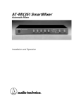
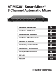
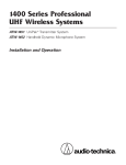
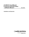
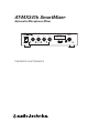
AT-MX341b SmartMixer
®
Automatic Microphone Mixer
AUTOMATIC MICROPHONE MIXER
Gain 1
Gain 2
Gain 3
AT-MX341b
Master
Threshold
Output Level
Gain 4
-20
-10
-6
-3
0
+3
+6
Priority Pre-select
Manual
Power
Selected Channel
Installation and Operation
1 2 3 4
Master
Level
Lockout
Contents
Introduction
.....................................................................................................................3
‚
What is a SmartMixer ? .........................................................................................................3
Features ..................................................................................................................................3
Front Panel .............................................................................................................................4
Rear Panel ..............................................................................................................................5
Installation and Setup ..............................................................................................6
Priority Microphones and Lockout Bus ................................................................................6
Preamplifier Gain ...................................................................................................................7
Output Gain ............................................................................................................................7
Phantom Power .....................................................................................................................7
Output Level LED Meter ........................................................................................................8
Adjusting “Off” Attenuation .................................................................................................8
Control Voltage Out ...............................................................................................................9
Daisy-chaining Mixers .........................................................................................................10
Rack Mounting .....................................................................................................................10
Security Caps .......................................................................................................................10
Specifications ...............................................................................................................11
Caution
To prevent fire or shock hazard, do not expose this apparatus to rain or moisture.
To avoid electric shock, do not open the cabinet.
Refer servicing to qualified personnel only.
To prevent fire, do not place any naked flame sources (such as lighted candles) on this apparatus.
To prevent fire, do not cover the ventilation of this apparatus with newspapers, table-clothes, curtains, etc.
Do not expose this apparatus to drips or splashes.
Do not place any objects filled with liquids, such as vases, on this apparatus.
Do not install this apparatus in a confined space such as a bookcase or similar unit.
Install this apparatus only in places where ventilation is good.
This apparatus should be located close enough to the AC outlet so that you can easily grasp the AC adapter at any time.
In case of emergency, disconnect the AC adapter quickly.
Compliance with FCC rules (USA only)
This class B Digital device complies with part 15 of the FCC Rules. Operation is subject to the following two conditions: (1) This device may not cause harmful interference, and (2) this device must accept any interference received,
including interference that may cause undesired operation.
Caution for FCC
You are cautioned that any changes or modifications not expressly approved in this manual could void your authority
to operate this equipment.
Note: This equipment has been tested and found to comply with the limits for a Class B digital device, pursuant to
part 15 of the FCC Rules. These limits are designed to provide reasonable protection against harmful interference in
a residential installation. This equipment generates, uses and can radiate radio frequency energy and, if not installed
and used in accordance with the instructions, may cause harmful interference to radio communications. However,
there is no guarantee that interference will not occur in a particular installation. If this equipment does cause harmful
interference to radio or television reception, which can be determined by turning the equipment off and on, the user
is encouraged to try to correct the interference by one or more of the following measures:
--Reorient or relocate the receiving antenna.
--Increase the separation between the equipment and receiver.
--Connect the equipment into an outlet on a circuit different from that to which the receiver is connected.
--Consult the dealer or an experienced radio/TV technician for help.
IC statement (Canada only)
This Class B digital apparatus complies with Canadian ICES-003.
Cet appareil numerique de la classe B est conforme a la norme NMB-003 du Canada.
2
Introduction
Please Note!
This manual assumes use of microphone-level inputs and line-level output, the most typical
SmartMixer application. However, all inputs and the output may be individually switched
internally to achieve any combination of mic- and line-level input/output. See page 8 for details.
About internal adjustment
Operating personnel must not remove equipment covers. Only qualified, experienced, authorized
service personnel may remove equipment covers for any internal adjustments.
Important caution for service personnel making internal adjustments
High voltages are present when the unit’s power cord is plugged into an electrical outlet. Service
personnel should not make any internal adjustments with power cable connected. Disconnect
the power cord from its source before removing equipment cover, because of the danger of touching an internal high voltage part. Also, to avoid injury, take care not to touch any sharp edges
within the unit, its top panel or interior sections.
What is a SmartMixer ® ?
The AT-MX341b SmartMixer® Automatic Microphone Mixer is a microprocessor controlled, automatic switching, four-channel microphone mixer.
The microphone inputs are XLRF-type balanced, with 12-volt phantom power available on pins 2
and 3. The output is XLRM-type balanced, non-inverting.
AT-MX341-model mixers can be daisy-chained via the included AT8325/1.0 Link Cable and special
connectors on the rear panel. The control bus and the audio are carried between mixers by the link
cable. The result is that all microphones on a multi-mixer system can be controlled by one microphone connected to any mixer. Since all of the mixers are independently powered, there is no
practical limit to the number of SmartMixers that can be daisy-chained.
Features
To custom-tailor conferencing needs, the mode of each microphone channel can be independently
switched via the front panel “priority pre-select” DIP switches. The combination of switch settings
results in three different modes of priority selection/operation. In any of the three modes of automatic operation, when everyone stops talking, the last microphone “on” will remain “on.” In a
teleconferencing, recording, or broadcast application, this feature will provide continuous room
ambience. This feature is cascaded throughout all linked mixers so that only one microphone in
the entire system will remain on.
Each input channel has an independent gain control on the front panel. Substantial gain reserve
and adjustment range permits microphones of widely differing sensitivities to be used together
successfully.
When a microphone is “off,” its input is only attenuated. This attenuation is factory set at
8 dB. The amount of “off” attenuation can be internally adjusted between 6 dB and 20 dB if
desired. (See page 8, “Adjusting ‘Off ’ Attenuation.”)
A “manual” setting on the front panel bypasses the AT-MX341b’s automatic switching and attenuation functions, causing the unit to behave like a conventional 4-channel mixer. In this mode, the
relative level of each microphone is strictly a function of the position of its respective front-panel
gain control.
3
AT-MX341b Front Panel
1. Power switch.
2. Power “on” indicator.
3. Input Gain controls. Adjust inputs for microphone sensitivities and/or
operating conditions.
4. Selected Channel LED indicators. Indicate which channels are “on” or “active.”
5. Output Level LED meter. Indicates RMS output level of the mixer. “Zero” (0) level is
factory calibrated for an output of +4 dBm into 600 ohms (Master Level control fully
clockwise). Can be set for peak output level indication via internal switch (see page 8).
6. Priority Pre-select switches. A switch in the “up” position assigns the respective
channel priority over the other channels. A priority channel can not be locked out by
other channels. Any combination of priority/non-priority selections is allowed.
7. Master Level control. Normal setting is fully clockwise (full output). If reducing the
mixer’s output is necessary, carefully turn the control counter-clockwise as needed with
a small screwdriver. Once set as desired, the control may be protected from unauthorized
adjustment by covering the panel hole with a sticker provided with the security caps.
(This control does not affect the meter indication.)
8. Master Threshold / Manual control. Sets the reference level that must be exceeded
for a microphone to be considered “in use.” Adjust to keep background noise level from
triggering microphones. “Manual” setting bypasses all of the SmartMixer’s automatic
functions.
9. Lockout LED indicator. Shows when lockout bus is active. Also aids in setting
Master Threshold.
➋
➎
➑
Output Level
Master
Threshold
➌
AUTOMATIC MICROPHONE MIXER
Gain 1
Gain 2
Gain 3
AT-MX341b
Gain 4
-20
-10
-6
-3
0
+3
+6
Priority Pre-select
Manual
Power
Selected Channel
➊
➍
Figure 1. Front panel
4
4
Control Voltage Out
3
2
1 GND
1 2 3 4
Master
Level
Lockout
➏
➐
➒
AT-MX341a Rear Panel
AUTOMATIC MICROPHONE MIXER
AT-MX341b
Master
Output
Level
1. Power input. Gain
Requires
12
volts AC
or 15-18Gain
volts
DC, either
polarity;
300 mA.
Threshold
1
Gain 2
Gain 3
4
0
-3
+3 +6
-20 -10 -6
2. Link In /Out. Provides for daisy-chaining of multiple mixers
when
more
than four
microphones are used.
Priority Pre-select
Manual
3. Control Voltage Out. Provides 0 to +4 VDC (active high) to trigger external
devices
such
Master
1 2 3 4
Level
as Power
speaker switching,Selected
camera
switching and indicator lights.
Lockout
Channel
4. Output. Balanced line-level output. Can be changed to mic-level output via internal
switch (see page 7). XLRM-type connector.
5. Inputs. Balanced microphone inputs for low impedance dynamic or condenser mics.
Can be changed to line-level inputs via internal switches (see page 7). XLRF-type connectors.
➌
4
3
2
➎
➍
1 GND
Control Voltage Out
12V AC/15-18V DC
Link In Link Out
➊
➋
Output
Input 4
Input 3
Input 2
Input 1
Figure 2. Rear panel
5
Installation and Setup
AT-MX341b SmartMixer setup tips:
1. Turn Master Threshold control to minimum threshold, immediately clockwise of the
“Manual” setting.
2. Set all Priority DIP switches to “down” position.
3. Turn all four microphone Gain controls fully counter-clockwise.
4. Connect the AC adapter to the mixer and plug in to outlet.
5. Turn Power switch “on.” The mixer will perform a self-test and turn each microphone
“on” and “off ” consecutively.
6. Connect a microphone to Input 1 and turn the Gain 1 control to the “nine o’clock”
position. The channel 1 LED will light if the microphone is operational.
7. Adjust the Gain 1 control for proper meter indication when speaking into microphone
(peaks at 0).
8. Gradually increase the Master Threshold control until the Lockout LED flashes when
speaking at a normal level.
9. Plug in up to three other microphones and adjust each respective Gain control for proper
meter indication. It should not be necessary to readjust the threshold level.
10. Priority can be assigned to one or more microphones by moving the appropriate DIP
switch(es) to the “up” position. Any microphone(s) assigned in this manner cannot be
locked out by any other microphone.
11. “Manual” mode can be selected at any time by simply turning the Master Threshold
control fully counterclockwise. In this mode, the unit will behave like a conventional
four-channel microphone mixer (all automatic functions are bypassed).
12. The Master Level recessed control on the front panel may be adjusted with a small
screwdriver if necessary. This control is at the last stage in the mixer, and does not affect
microphone gain, threshold setting, or meter indication.
Priority Microphones and the Lockout Bus
Once the Master Threshold control has been properly adjusted, an audio signal appearing in any
channel causes the lockout control bus to activate and the Lockout LED indicator to light. The
Priority Pre-select switches then determine whether or not a particular mic is affected by lockouts
caused by other mics: a channel Priority switch in the “down” position will allow
lockout* of its mic; the same switch “up” will not allow lockout of its mic.
* Note that any mic which is described as “locked out” or “off ” is really just being attenuated by
between 6 dB and 20 dB from the level otherwise determined by its Gain control setting,
sensitivity and placement. See the “Daisy-chaining Mixers” section on page 10 for further details.
There are basically three “modes” of automatic operation:
Mode 1... All Priority Pre-select switches Up
The Lockout indicator will come on with any audio input, but no mic will be locked out…because
none are connected to the lockout bus. (This mode is often called
“Free-for-all”…or sometimes “City Council”!)
6
Mode 2…All Priority Pre-select switches Down
In this mode, only one mic at a time can be “on.” The lockout bus shuts down all other mics until
the first speaker pauses. As soon as the controlling microphone goes silent, the lockout bus goes
inactive and any other mic can come on. This switching takes place without any
syllable-grabbing delay, or pops or clicks. (This mode is known as “First-come-first-served”
or “Filibuster.”)
This mode is very useful when the gain setting of the overall sound system must be close to the
threshold of feedback, and additional microphones coming on could throw the system into feedback. The SmartMixer will not allow multiple microphones to be on at the same time in this mode.
The switching is so fast and silent that the meeting can still be completely interactive.
Mode 3…One Priority Pre-select switch Up
The selected priority microphone can come on at any time and can mute any other mic that is on
(popularly called “The Chairperson” mode).
(Note that there may be special circumstances where two or three mics could be set to priority,
so those speakers could talk whenever desired, but still mute one or two non-priority mics.)
If multiple SmartMixers are used with AT8325/1.0 Link Cables, Priority Pre-select switches on all
channels in use will have the control effects described above.
The selected priority microphone(s) will mute only those non-priority microphones within the
same unit.
Preamplifier Gain
The SmartMixer has a substantial gain range, allowing it to accept a wide variety of microphones. However, if in some instances higher-output microphones are used for close talking, it
may be necessary to reduce the preamplifier gain. This can be done by changing switch settings
inside the unit. With the unit unplugged, remove the two screws on each side of the unit and
remove the top cover. Locate the internal switches designated on the circuit board by “S103,”
“S203,” “S303” and “S403” (Figs. 3 and 4, page 8). Changing the settings of these internal
switches will cause a gain reduction of 10 dB for channels 1, 2, 3 and 4 respectively.
The preamplifier gain may be reduced further, allowing the SmartMixer to accept line-level
sources. Changing the settings of the internal switches designated by “S101,” “S102,” “S103”
and “S104” will cause an input reduction of 50 dB for channels 1, 2, 3 and 4 respectively. Note
that the appropriate internal switches can be used in combination for a total sensitivity reduction
of up to 60 dB for each channel.
Output Gain
The SmartMixer’s output is factory set at line level. Should mic-level output be desired, simply
unplug the unit, remove the top cover and locate the switch on the circuit board marked “S501”
(Figs. 3 and 4, page 8). Changing the setting of this switch will cause a 50 dB reduction in output.
Phantom Power
Each of the SmartMixer’s inputs supplies +12V DC phantom power. Should it be required to disable the phantom power, simply unplug the unit, remove the top cover and locate the switches
designated on the circuit board by “S102,” “S202,” “S302” and “S402” (Figs. 3 and 4, page 8).
Changing the settings of these switches will disable phantom power on channels 1, 2, 3 and 4,
respectively. Note that, although they do not require phantom power for operation, most balanced-output dynamic microphones can be used without disabling the SmartMixer’s phantom
power.
7
Rear Panel
Output Level LED Meter
The Output Level LED meter is factory set
to indicate RMS output. Should peak output
indication be desired, simply unplug the unit,
remove the top cover and change the setting
of the switch designated on the circuit board
by “S602” (Figs. 3 and 4). “Zero” (0) level is
factory-calibrated at +4 dBm into 600 ohms.
Don't Touch !
Figure 3. Internal view of mixer.
OFF
0dB
LINE
S602
S403
-10dB
MIC
S501
ON
OUTPUT ATT
MIC
S402
0dB
PAD
-10dB
LINE
S401
OFF
S303
PAD
0dB
ON
INPUT ATT PHANTOM
-10dB
MIC
S302
OFF
S203
PAD
0dB
S103
PAD
-10dB
ON
LINE
S301
OFF
MIC
S202
S102
ON
INPUT ATT PHANTOM
MIC
LINE
S201
INPUT ATT PHANTOM
S101
INPUT ATT PHANTOM
LINE
PEAK
RMS
METER RESPONSE
VR102
GATE ATT
-20dB
-6dB
VR202
VR302
GATE ATT
-20dB
-6dB
GATE ATT
-20dB
-6dB
VR402
GATE ATT
-20dB
-6dB
Figure 4. Detail of internal controls.
Adjusting ”Off” Attenuation
In instances when the number of microphones in use is high, it may be necessary to increase the
amount of “off ” attenuation per microphone to keep the total ambient noise level low. There are
“off ” attenuation adjustments inside the unit. To adjust the “off ” attenuation of channel 1,
unplug the unit, remove the top cover and locate the trimpot designated on the circuit board by
“VR102” (Figs. 3 and 4). It is factory set at approximately 8 dB, the attenuation at the middle of
the control’s rotation. When the control is turned fully counter-clockwise, “off ” attenuation is
approximately 20 dB. Conversely, when the adjustment is turned fully clockwise, “off ” attenuation is approximately 6 dB. VR202, VR302 and VR402 control “off ” attenuation for channels 2, 3
and 4 respectively.
8
Control Voltage Out
When a microphone channel turns “on,” as indicated by a Selected Channel LED on the front
panel, the channel’s associated Control Voltage Out goes “high” (+4 VDC). This signal can be
used to light indicator lamps, switch speaker zones on and off, select video cameras, etc. The
control voltage should not be connected directly to an inductive load such as a relay coil, as damage to the mixer may result. Several interface circuit possibilities are shown in Figure 5.
Figure 5. Control interface examples.
9
Daisy-chaining Mixers
When more than four microphones are needed, it is possible to daisy-chain multiple SmartMixers
together through the Link In/Out connectors on the backs of the units (Fig. 2). Connect Mixer #1
Link Out jack to Mixer #2 Link In jack, etc. Mixer #1 output contains only audio from the first four
microphones; Mixer #2 output then contains audio from all the microphones plugged into Mixer
#1 and the microphones plugged into Mixer #2. The last mixer in the chain contains audio from all
preceding mixers. The combined output is then taken from the last mixer in the chain. Because
lockout information is passed between mixers through Link In / Out, the last-microphone-on condition is not violated. Thus only one microphone per installation will stay on when no one is speaking.
Note that one or more mixers can be switched to “Manual” mode without affecting the automatic
operation of any other mixers in the chain.
Rack Mounting
Provided with each mixer are two rack ears, one long and one short, and six self-tapping screws
to attach the ears to the unit. When using more than one SmartMixer in a system, it may be
advantageous to mount two mixers in a 1U rack space. This can be accomplished using the two
short rack ears and an optional joining plate (Model AT8628), which allows two units to be connected side-by-side in a single rack space.
Security Caps
For permanent installations where microphone selections, positions and acoustic conditions are
constant, it may be advantageous to remove the front panel knobs and install security caps to prevent unauthorized adjustments. To install, simply press the caps into place, covering the Gain and
Threshold controls. Place the provided sticker over the Master Level access opening in the panel.
The system should be tested carefully before installing the security caps because they are intended to be “permanent” and are very difficult to remove.
If removal of installed security caps becomes necessary, first remove the two screws on each
side of the unit and remove the top cover. Then remove the six screws that attach the front panel:
four on top and two underneath. Remove the front panel. With the panel removed, the two locking tabs on each security cap can be accessed. The cap can be released by carefully squeezing
the two tabs together.
10
Specifications
†
Input Impedance
Mic . . . . . . . . . . . . . . . . . . . . . . . . . . . 4,000 ohms
Line . . . . . . . . . . . . . . . . . . . . . . . . . . . 30,000 ohms
Output Impedance
Line . . . . . . . . . . . . . . . . . . . . . . . . . . . 200 ohms
Mic . . . . . . . . . . . . . . . . . . . . . . . . . . . 320 ohms
Maximum Input Level
Mic . . . . . . . . . . . . . . . . . . . . . . . . . . . –20 dBV
Line . . . . . . . . . . . . . . . . . . . . . . . . . . . +30 dBV
Maximum Output Level*
Line . . . . . . . . . . . . . . . . . . . . . . . . . . .
Mic . . . . . . . . . . . . . . . . . . . . . . . . . . .
Nominal Output Level (0 VU)*
Line . . . . . . . . . . . . . . . . . . . . . . . . . . .
Mic . . . . . . . . . . . . . . . . . . . . . . . . . . .
+14 dBm (600 ohms)
–40 dBm (600 ohms)
+4 dBm (600 ohms), +4.4 dBV (open circuit)
–46 dBm (600 ohms), –44 dBV (open circuit)
Maximum Gain . . . . . . . . . . . . . . . . . . . . ≧70 dB
Frequency Response . . . . . . . . . . . . . . . 60 Hz to 30 kHz at –3 dB points
Dynamic Range1 . . . . . . . . . . . . . . . . . . . 75 dB ±10 dB, dependent upon gain control settings
Equivalent Input Noise . . . . . . . . . . . . . –120 dBV (150 ohms) at maximum gain
Input Attenuation . . . . . . . . . . . . . . . . . . 10 dB
Mic/Line Input Pads . . . . . . . . . . . . . . . . 50 dB
Microphone Phantom Power . . . . . . . . +12V DC
Control Voltage Out . . . . . . . . . . . . . . . . +4V DC
Power Supply . . . . . . . . . . . . . . . . . . . . . . 12V AC or 15-18V DC, either polarity; 300 mA
Operating Temperature . . . . . . . . . . . . . 32° to 104° (0° to 40° C)
Dimensions . . . . . . . . . . . . . . . . . . . . . . . . 8.25" (210 mm) W x 9.38" (238 mm) D x 1.75"
(44 mm) H (including feet, knobs and connectors)
Weight . . . . . . . . . . . . . . . . . . . . . . . . . . . . 3.1 lbs. (1.4 kg)
Included Accessories . . . . . . . . . . . . . . . AC adapter, AT8325/1.0 Link Cable
Optional Accessory . . . . . . . . . . . . . . . . AT8628 Double Rackmount Joining Plate
†
In the interest of standards development, A.T.U.S. offers full details on its test
methods to other industry professionals on request.
* Master Level control at maximum (fully clockwise).
1
Input terminated with 150 ohms, A-weighted using Audio Precision System One.
Summary of Internal Controls
Function
Ch 1
Ch 2
Ch 3
Ch 4
Output
50 dB Mic /Line Atten.
S101
S102
S103
S104
S501
12V Phantom Power
S102
S202
S302
S402
--
10 dB Input Atten.
S301
S302
S303
S403
--
“Off” Attenuation
VR102
VR202
VR302
VR402
--
--
--
S602
Meter RMS/Peak
--See diagram on page 8 for locations/positions.
11
P52324 ©2011