1
SiE25-110
Service
Manual
Split System Air Conditioners
SkyAir R-407C
Super Inverter 70
D Series
[Applied Models]
SkyAir : Inverter Heat Pump
SiE25-110
Split-System
Air Conditioners
SkyAir Super Inverter 70
D Series
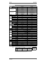
1. Introduction ............................................................................................ V
1.1 Safety Cautions ....................................................................................... v
SkyAir Super Inverter 70 D Series Heat Pump ..............................1
Part1
Model Name and Power Supply .........................................3
1. Model Name and Power Supply..............................................................4
1.1 Model Name and Power Supply .............................................................. 4
1.2 External Appearance ............................................................................... 5
Part 2 Functions ............................................................................7
1. List of Functions ......................................................................................8
1.1 Functions ................................................................................................. 8
Part 3 Specifications...................................................................11
1. Specifications ........................................................................................12
1.1 50Hz ...................................................................................................... 12
1.2 60Hz ...................................................................................................... 18
1.3 Comply with Australian Standard (50Hz)............................................... 20
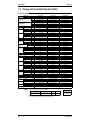
Part 4 Remote Controller ............................................................23
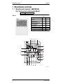
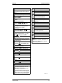
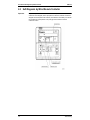
1. Wired Remote Controller.......................................................................24
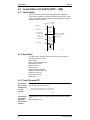
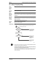
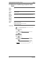
1.1 Wired Remote Controller - NEW MODEL
(For Cooling only and heat-pump Model) .............................................. 24
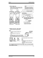
1.2 Installation ............................................................................................. 26
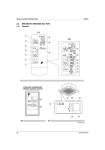
2. Wireless Remote Controller ..................................................................28
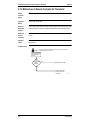
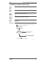
2.1 Wireless Remote Controller................................................................... 28
Part 5 Field Piping and Wiring ....................................................31
1. Field Piping and Wiring .........................................................................32
1.1 Precautions............................................................................................ 32
1.2 Field Piping............................................................................................ 35
1.3 Field Wiring............................................................................................ 37
Table of Contents
i
SiE25-110
Part 6 Field Setting .....................................................................39
1. Method of Field Set (Reset after Maintenance Inspection/Repair) .......40
1.1
1.2
1.3
1.4
1.5
1.6
Explanation............................................................................................ 40
Field Setting........................................................................................... 41
Initial Setting Contents........................................................................... 43
Local Setting Mode No. ......................................................................... 44
Detailed Explanation of Setting Modes.................................................. 46
Centralized Group No. Setting............................................................... 52
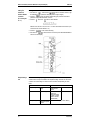
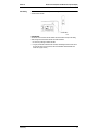
2. Settings Concerning Maintenance ........................................................53
2.1 Indoor Unit PCB..................................................................................... 53
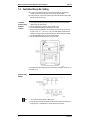
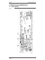
2.2 Outdoor Unit Switches / Setting Jumper................................................ 57
3. Existence of DIP Switch, Jumper and BS .............................................60
3.1
3.2
3.3
3.4
Reference Table .................................................................................... 60
Initial DIP Switch Setting List (Factory Set) ........................................... 62
Emergency Operation............................................................................ 63
Maintenance Mode Setting.................................................................... 64
Part 7 Function and Operation ...................................................65
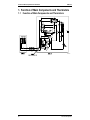
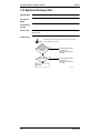
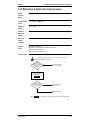
1. Function of Main Components and Thermistors ...................................66
1.1 Function of Main Components and Thermistors.................................... 66
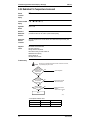
2. Function Outline ....................................................................................68
2.1 Indoor Unit ............................................................................................. 68
2.2 Outdoor Unit .......................................................................................... 69
3. Electric Function Parts ..........................................................................71
3.1 Indoor Unit ............................................................................................. 71
3.2 Outdoor Unit .......................................................................................... 72
4. Function Details ....................................................................................74
4.1 Indoor Unit ............................................................................................. 74
4.2 Inverter Outdoor Unit (R-407C) (RZP71 ~ 140D).................................. 82
5. Operation Range...................................................................................98
5.1 Operation Limits .................................................................................... 98
Part 8 Troubleshooting ...............................................................99
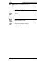
1. Maintenance Inspections ....................................................................101
1.1 Optimal Operation Condition ............................................................... 101
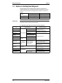
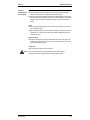
1.2 Cautions in Handling New Refrigerant ................................................ 104
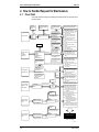
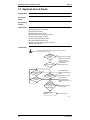
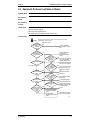
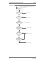
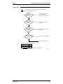
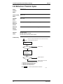
2. How to Handle Request for Maintenance ...........................................106
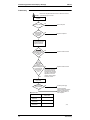
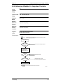
2.1 Flow Chart ........................................................................................... 106
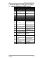
3. Troubleshooting Based on Equipment Condition................................107
3.1
3.2
3.3
3.4
3.5
3.6
3.7
3.8
3.9
3.10
ii
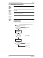
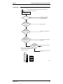
Troubleshooting Based on Equipment Condition ................................ 107
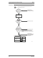
Equipment does not Operate............................................................... 108
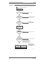
Indoor Fan Operates, but Compressor does not. ................................ 109
Cooling/Heating Operation Starts but Stops Immediately. .................. 111
After Equipment Shuts Down, It cannot be Restarted for a While....... 112
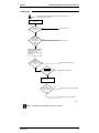
Equipment Operates but does not Provide Cooling. ........................... 113
Equipment Operates but does not Provide Heating. ........................... 115
Equipment Discharges White Mist....................................................... 116
Equipment Produces Loud Noise or Shakes....................................... 117
Equipment Discharges Dust. ............................................................... 118
Table of Contents
SiE25-110
3.11 Remote Controller LCD Displays "88". ................................................ 119
3.12 Swing Flap does not Operate .............................................................. 120
4. Procedure of Self-Diagnosis by Remote Controller ............................121
4.1
4.2
4.3
4.4
The INSPECTION/TEST Button.......................................................... 121
Self-Diagnosis by Wired Remote Controller ........................................ 122
Fault Diagnosis by Wireless Remote Controller .................................. 123
Remote Controller Display Malfunction Code and Contents ............... 125
5. Procedure of Self-Diagnosis by LED...................................................127
5.1 Troubleshooting by LED on the Indoor Unit’s...................................... 127
5.2 Troubleshooting by LED on Inverter Outdoor Unit PCB ...................... 128
6. Troubleshooting by Remote Controller Display / LED Display............130
6.1
6.2
6.3
6.4
6.5
6.6
6.7
6.8
6.9
6.10
6.11
6.12
6.13
6.14
6.15
6.16
6.17
6.18
6.19
6.20
6.21
6.22
6.23
6.24
6.25
6.26
6.27
6.28
6.29
6.30
6.31
6.32
6.33
6.34
6.35
6.36
6.37
6.38
Table of Contents
Explanation for Symbols...................................................................... 130
Malfunction Code and LED Display Table........................................... 131
Failure of Indoor Unit PC Board .......................................................... 134
Malfunction of Drain Water Level System (Float Type) ....................... 135
Failure of Drain System ....................................................................... 137
Indoor Unit Fan Motor Lock ................................................................. 138
Malfunction of Indoor Unit Fan Motor .................................................. 139
Swing Flap Motor Malfunction / Lock................................................... 141
Failure of Capacity Setting .................................................................. 143
Malfunction of Heat Exchange Temperature Sensor System.............. 144
Malfunction of Suction Air Temperature Sensor System..................... 145
Malfunction of Remote Controller Air Thermistor ................................ 146
Malfunction of Moisture Sensor System .............................................. 147
Actuation of Protection Device ............................................................ 148
Failure of Outdoor Unit PC Board........................................................ 149
Abnormal High Pressure Level............................................................ 150
Low Pressure System (LPS) Malfunction ............................................ 152
Compressor Motor Lock ...................................................................... 153
Malfunction of Outdoor Unit Fan Motor ............................................... 155
Malfunction of Electronic Expansion Valve.......................................... 156
Malfunction of Discharge Pipe Temperature ....................................... 158
Malfunction of High Pressure Switch System...................................... 160
Malfunction of outdoor fan motor signal .............................................. 161
Malfunction of Thermistor System ....................................................... 162
Malfunction of Suction Pipe Pressure Sensor ..................................... 163
Radiation Fin Temperature Increased ................................................. 164
DC Output Overcurrent (Instantaneous).............................................. 165
Electronic Thermal (Time Lag) ............................................................ 167
Stall Prevention (Time Lag) ................................................................. 169
Malfunction of Transmission system
(Between Control PCB and Inverter PCB)........................................... 171
Open Phase......................................................................................... 173
Malfunction of Radiator Fin Temperature Thermistor.......................... 175
Malfunction of Radiator Fin Temperature Thermistor.......................... 176
Failure of Capacity Setting .................................................................. 177
Gas Shortage (Malfunction)................................................................. 178
Abnormal Power Supply Voltage......................................................... 179
Malfunction of Transmission (Between Indoor and Outdoor Unit)....... 181
Malfunction of Transmission
(Between Indoor Unit and Remote Controller) .................................... 183
iii
SiE25-110
6.39 Transmission Error Between Main Remote Controller
and Sub Remote Controller ................................................................. 184
6.40 Malfunction of Field Setting Switch...................................................... 185
6.41 Centralized Address Setting Error ....................................................... 187
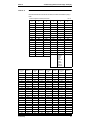
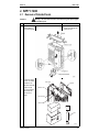
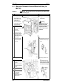
Part 9 Removal Procedure ........................................................195
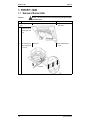
1. FHYCP71~140D .................................................................................196
1.1
1.2
1.3
1.4
1.5
1.6
1.7
1.8
1.9
1.10
1.11
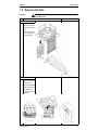
Removal of Suction Grille .................................................................... 196
Removal of Air Filter ............................................................................ 197
Removal of Decoration Panel.............................................................. 198
Removal of Horizontal Blade ............................................................... 200
Removal of Swing Motor ..................................................................... 201
Removal of Switch Box........................................................................ 203
Removal of PC Board.......................................................................... 205
Removal of Humidity Sensor and Air Temperature Thermistor........... 207
Removal of Fan Motor ......................................................................... 208
Removal of Drain Pan, Drain Pump, Float Switch............................... 210
Removal of Heat Exchanger Temperature Thermistor........................ 212
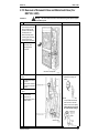
2. RZP71~140D ......................................................................................213
2.1
2.2
2.3
2.4
2.5
2.6
2.7
2.8
2.9
2.10
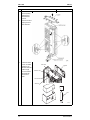
Removal of Outside Panels ................................................................. 213
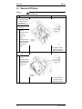
Removal of Propeller Fan and Fan Motor ........................................... 215
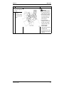
Removal of PC Board.......................................................................... 216
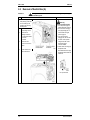
Removal of Switch Box (A).................................................................. 218
Removal of Switch Box (B).................................................................. 219
Removal of Compressor(For RZP71D) ............................................... 220
Removal of Compressor(For RZP100~140D) ..................................... 221
Removal of Four Way Valve................................................................ 223
Removal of Solenoid Valve and Motorized Valve (For RZP71D) ........ 224
Removal of Solenoid Valve and Motorized Valve
(For RZP100~140D)............................................................................ 225
2.11 Removal of Pressure Switch and Pressure Sensor............................. 226
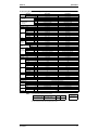
Part 10 Appendix.........................................................................227
1. Piping Diagrams..................................................................................228
1.1 Pair system.......................................................................................... 228
1.2 Twin System ........................................................................................ 229
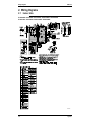
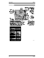
2. Wiring Diagrams..................................................................................230
2.1 Indoor Units ......................................................................................... 230
2.2 Outdoor Units ...................................................................................... 234
Index
.............................................................................................i
Drawings & Flow Charts ................................................................ v
iv
Table of Contents
SiE25-110
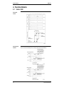
Introduction
1. Introduction
1.1
Safety Cautions
Cautions and
Warnings
Be sure to read the following safety cautions before conducting repair work.
Warning” and “
Caution”. The “
Warning”
The caution items are classified into “
items are especially important since they can lead to death or serious injury if they are not
Caution” items can also lead to serious accidents under some
followed closely. The “
conditions if they are not followed. Therefore, be sure to observe all the safety caution items
described below.
About the pictograms
This symbol indicates an item for which caution must be exercised.
The pictogram shows the item to which attention must be paid.
This symbol indicates a prohibited action.
The prohibited item or action is shown inside or near the symbol.
This symbol indicates an action that must be taken, or an instruction.
The instruction is shown inside or near the symbol.
After the repair work is complete, be sure to conduct a test operation to ensure that the
equipment operates normally, and explain the cautions for operating the product to the
customer.
1.1.1 Caution in Repair
Warning
Be sure to disconnect the power cable plug from the plug socket before
disassembling the equipment for a repair.
Working on the equipment that is connected to a power supply can cause an
electrical shook.
If it is necessary to supply power to the equipment to conduct the repair or
inspecting the circuits, do not touch any electrically charged sections of the
equipment.
If the refrigerant gas discharges during the repair work, do not touch the
discharging refrigerant gas.
The refrigerant gas can cause frostbite.
When disconnecting the suction or discharge pipe of the compressor at the
welded section, release the refrigerant gas completely at a well-ventilated
place first.
If there is a gas remaining inside the compressor, the refrigerant gas or
refrigerating machine oil discharges when the pipe is disconnected, and it can
cause injury.
If the refrigerant gas leaks during the repair work, ventilate the area. The
refrigerant gas can generate toxic gases when it contacts flames.
The step-up capacitor supplies high-voltage electricity to the electrical
components of the outdoor unit.
Be sure to discharge the capacitor completely before conducting repair work.
A charged capacitor can cause an electrical shock.
Do not start or stop the air conditioner operation by plugging or unplugging the
power cable plug.
Plugging or unplugging the power cable plug to operate the equipment can
cause an electrical shock or fire.
v
Introduction
SiE25-110
Caution
Do not repair the electrical components with wet hands.
Working on the equipment with wet hands can cause an electrical shock.
Do not clean the air conditioner by splashing water.
Washing the unit with water can cause an electrical shock.
Be sure to provide the grounding when repairing the equipment in a humid or
wet place, to avoid electrical shocks.
Be sure to turn off the power switch and unplug the power cable when cleaning
the equipment.
The internal fan rotates at a high speed, and cause injury.
Do not tilt the unit when removing it.
The water inside the unit can spill and wet the furniture and floor.
Be sure to check that the refrigerating cycle section has cooled down
sufficiently before conducting repair work.
Working on the unit when the refrigerating cycle section is hot can cause burns.
Use the welder in a well-ventilated place.
Using the welder in an enclosed room can cause oxygen deficiency.
1.1.2 Cautions Regarding Products after Repair
Warning
Be sure to use parts listed in the service parts list of the applicable model and
appropriate tools to conduct repair work. Never attempt to modify the
equipment.
The use of inappropriate parts or tools can cause an electrical shock,
excessive heat generation or fire.
When relocating the equipment, make sure that the new installation site has
sufficient strength to withstand the weight of the equipment.
If the installation site does not have sufficient strength and if the installation
work is not conducted securely, the equipment can fall and cause injury.
Be sure to install the product correctly be using the provided standard
installation frame.
Incorrect use of the installation frame and improper installation can cause the
equipment to fall, resulting in injury.
Be sure to install the product securely in the installation frame mounted on a
window frame.
If the unit is not securely mounted, it can fall and cause injury.
Be sure to use an exclusive power circuit for the equipment, and follow the
technical standards related to the electrical equipment, the internal wiring
regulations and the instruction manual for installation when conducting
electrical work.
Insufficient power circuit capacity and improper electrical work can cause an
electrical shock on fire.
vi
For integral units
only
For integral units
only
SiE25-110
Introduction
Warning
Be sure to use the specified cable to connect between the indoor and outdoor
units. Make the connections securely and route the cable properly so that there
is no force pulling the cable at the connection terminals.
Improper connections can cause excessive heat generation or fire.
When connecting the cable between the indoor and outdoor units, make sure
that the terminal cover does not lift off or dismount because of the cable.
If the cover is not mounted properly, the terminal connection section can cause
an electrical shock, excessive heat generation or fire.
Do not damage or modify the power cable.
Damaged or modified power cable can cause an electrical shock or fire.
Placing heavy items on the power cable, and heating or pulling the power cable
can damage the cable.
Do not mix air or gas other than the specified refrigerant (R-407C) in the
refrigerant system.
If air enters the refrigerating system, an excessively high pressure results,
causing equipment damage and injury.
If the refrigerant gas leaks, be sure to locate the leak and repair it before
charging the refrigerant. After charging refrigerant, make sure that there is no
refrigerant leak.
If the leak cannot be located and the repair work must be stopped, be sure to
perform pump-down and close the service valve, to prevent the refrigerant gas
from leaking into the room. The refrigerant gas itself is harmless, but it can
generate toxic gases when it contacts flames, such as fan and other heaters,
stoves and ranges.
When replacing the coin battery in the remote controller, be sure to disposed
of the old battery to prevent children from swallowing it.
If a child swallows the coin battery, see a doctor immediately.
Caution
Installation of a leakage breaker is necessary in some cases depending on the
conditions of the installation site, to prevent electrical shocks.
Do not install the equipment in a place where there is a possibility of
combustible gas leaks.
If a combustible gas leaks and remains around the unit, it can cause a fire.
Be sure to install the packing and seal on the installation frame properly.
For integral units
If the packing and seal are not installed properly, water can enter the room and only
wet the furniture and floor.
1.1.3 Inspection after Repair
Warning
Check to make sure that the power cable plug is not dirty or loose, then insert
the plug into a power outlet all the way.
If the plug has dust or loose connection, it can cause an electrical shock or fire.
If the power cable and lead wires have scratches or deteriorated, be sure to
replace them.
Damaged cable and wires can cause an electrical shock, excessive heat
generation or fire.
Do not use a joined power cable or extension cable, or share the same power
outlet with other electrical appliances, since it can cause an electrical shock,
excessive heat generation or fire.
vii
Introduction
SiE25-110
Caution
Check to see if the parts and wires are mounted and connected properly, and
if the connections at the soldered or crimped terminals are secure.
Improper installation and connections can cause excessive heat generation,
fire or an electrical shock.
If the installation platform or frame has corroded, replace it.
Corroded installation platform or frame can cause the unit to fall, resulting in
injury.
Check the grounding, and repair it if the equipment is not properly grounded.
Improper grounding can cause an electrical shock.
Be sure to measure the insulation resistance after the repair, and make sure
that the resistance is 1 Mohm or higher.
Faulty insulation can cause an electrical shock.
Be sure to check the drainage of the indoor unit after the repair.
Faulty drainage can cause the water to enter the room and wet the furniture
and floor.
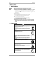
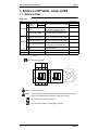
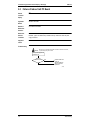
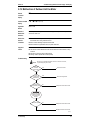
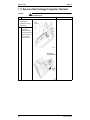
1.1.4 Using Icons
Icons are used to attract the attention of the reader to specific information. The meaning of each
icon is described in the table below:
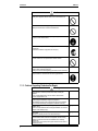
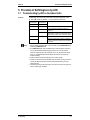
1.1.5 Using Icons List
Icon
Type of
Information
Note
Description
Caution
A “caution” is used when there is danger that the reader, through
incorrect manipulation, may damage equipment, loose data, get
an unexpected result or has to restart (part of) a procedure.
Warning
A “warning” is used when there is danger of personal injury.
Reference
A “reference” guides the reader to other places in this binder or
in this manual, where he/she will find additional information on a
specific topic.
A “note” provides information that is not indispensable, but may
nevertheless be valuable to the reader, such as tips and tricks.
Note:
Caution
Warning
viii
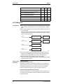
SiE25-110
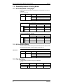
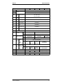
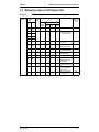
SkyAir Super Inverter 70
D Series
Heat Pump
Model Series
71
100
125
140
Pair
71D
100D
125D
140D
Twin
—
50D×2
60D×2
—
Pair
71B
100B
125B
—
Twin
—
45B×2
60B×2
—
FUYP
71B
100B
125B
—
FAYP
71B
100B
—
—
RZP
71D
100D
125D
140D
Class
FHYCP
Indoor Units FHYP
Outdoor
Units
1
SiE25-110
2
SiE25-110
Part 1
Model Name and
Power Supply
1. Model Name and Power Supply..............................................................4
1.1 Model Name and Power Supply .............................................................. 4
1.2 External Appearance ............................................................................... 5
Model Name and Power Supply
3
Model Name and Power Supply
SiE25-110
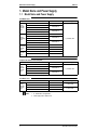
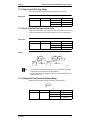
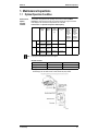
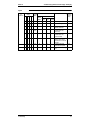
1. Model Name and Power Supply
1.1
Model Name and Power Supply
50Hz Model Series
Indoor Units
Outdoor Units
FHYCP71DVE
Ceiling
Mounted
Cassette
Type
FHYCP100DVE
FHYCP50DVE+FHYCP50DVE (Twin)
FHYCP125DVE
FHYCP60DVE+FHYCP60DVE (Twin)
FHYP71BV1
Ceiling
Suspended
Type
FHYP100BV1
FHYP45BV1+FHYP45BV1 (Twin)
FHYP125BV1
FHYP60BV1+FHYP60BV1 (Twin)
New Ceiling FUYP71BV1
Suspended FUYP100BV1
Cassette
Type
FUYP125BV1
Wall
Mounted
Type
Power Supply
RZP71DV1
RZP100DV1
RZP125DV1
RZP71DV1
RZP100DV1
1φ, 220-240V, 50Hz
RZP125DV1
RZP71DV1
RZP100DV1
RZP125DV1
FAYP71BV1
RZP71DV1
FAYP100BV1
RZP100DV1
Complied with Australian Standard (50Hz)
Indoor Units
Outdoor Units
FHYCP71DVE
Ceiling
Mounted
Cassette
Type
FHYCP100DVE
FHYCP50DVE+FHYCP50DVE (Twin)
FHYCP125DVE
FHYCP60DVE+FHYCP60DVE (Twin)
Power Supply
RZP71DV1
RZP100DV1
1φ, 220-240V, 50Hz
RZP125DV1
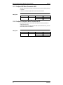
60Hz Model Series
Indoor Units
Ceiling
Mounted
Cassette
Type
Outdoor Units
FHYCP71DVL
RZP71DVAL
FHYCP100DVL
RZP100DVAL
FHYCP125DVL
RZP125DTAL
FHYCP140DVL
RZP140DTAL
Notes:
4
Power Supply
1φ, 220V, 60Hz
3φ, 220V, 60Hz
1. : New Model or Changed Model.
2. Power Supply Intake : Outdoor Units.
Model Name and Power Supply
SiE25-110
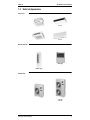
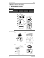
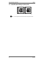
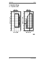
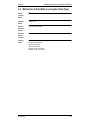
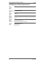
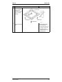
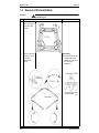
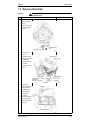
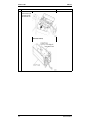
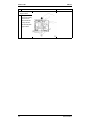
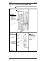
1.2
Model Name and Power Supply
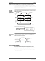
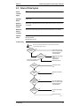
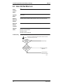
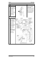
External Appearance
Indoor Units
FHYP-B
FHYCP-D
FUYP-B
FAYP-B
Remote Controller
Wired Type
Wireless Type
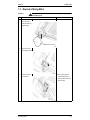
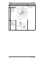
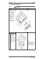
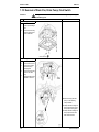
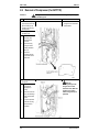
Outdoor Units
RZP71D
Model Name and Power Supply
RZP100D
RZP125D
RZP140D
5
Model Name and Power Supply
6
SiE25-110
Model Name and Power Supply
SiE25-110
Part 2
Functions
1. List of Functions ......................................................................................8
1.1 Functions ................................................................................................. 8
Functions
7
List of Functions
SiE25-110
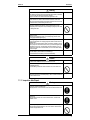
1. List of Functions
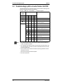
1.1
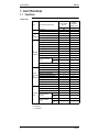
Functions
FHYCP / FUYP
Items
Model Type
Improved Points and Functions
Indoor Units
Outdoor Units
Appearance Improved
Main
Reduction of Dimensions or Weight
Improvement
Reduction of Operation Sound
For
Comfortable
Air
Conditioning
50~140D
New
New
New Ceiling
Mounted
Suspended
Cassette (FUYP)
71~125B
New
Ceiling Mounted
Super Cassette
(FHYCP)
Auto Restart
Fan Operation Mode
LCD Remote Controller (Option)
Auto Swing Function
Ceiling Soiling Prevention
—
Program Dry
High Fan Speed Mode
High Ceiling Application
—
—
—
—
Hot Start
Timer Selector
Fresh Air Intake Directly from the Unit
Drain Pump
—
—
Long Life Filter
—
—
—
—
—
Two Select Thermostat
Sensor
Wired Type
Wireless
Type
For Easy
Ultra-Long Life Filter (Option)
Construction
Mold
Resistant Treatment for Filter
and
Maintenance Filter Sign
Mold Resistant Drain Pan
Emergency Operation
Self Diagnosis Function
Set Back Time Clock
Double Remote Control
Group Control by 1 Remote Controller
Wired Type
For Flexible Control by External
Control
Wireless
Command
Type
Wired Type
Remote/Centralized
Wireless
Control
Type
: Improved Points and Functions
: No Change
— : No Functions
8
Functions
SiE25-110
List of Functions
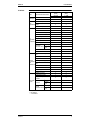
FHYP/FAYP
Items
Improved Points and Functions
Indoor Units
Outdoor Units
Appearance Improved
Main
Reduction of Dimensions or
Improvement Weight
Reduction of Operation Sound
Auto Restart
Fan Operation Mode
LCD Remote Controller (Option)
Auto Swing Function
Ceiling Soiling Prevention
For
Program Dry
Comfortable
High Fan Speed Mode
Air
Conditioning High Ceiling Application
Wired Type
Two Select
Thermostat Sensor Wireless
Type
Hot Start
Timer Selector
Fresh Air Intake Directly from the
Unit
Drain Pump
Long Life Filter
For Easy
Ultra-Long Life Filter (Option)
Construction Mold Resistant Treatment For
and
Maintenance Filter
Filter Sign
Mold Resistant Drain Pan
Emergency Operation
Self Diagnosis Function
Set Back Time Clock
Double Remote Control
Group Control by 1 Remote
Controller
For Flexible
Wired Type
Control by External
Control
Wireless
Command
Type
Wired Type
Remote/
Centralized Control Wireless
Type
Model Type
Ceiling Suspended
(FHYP)
50~125B
New
Wall Mounted
(FAYP)
71, 100B
New
—
—
—
—
—
—
—
—
—(Option)
—
—
—
—
—
—
: Improved Points and Functions
: No Change
— : No Functions
Functions
9
List of Functions
SiE25-110
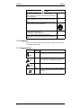
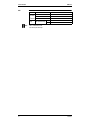
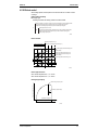
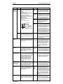
RZP
Note:
10
Items
For
Comfortable
Air
Conditioning
Functions
Inverter Control
PMV Control
MIO Control
Operation
Range
Wide Operation Range
Cooling
Heating
RZP71~140D
–5~50˚CDB
–15~15.5˚CWB
PMV : Predicted Mean Vote
MIO : Multi Input and Output
Functions
SiE25-110
Part 3
Specifications
1. Specifications ........................................................................................12
1.1 50Hz ...................................................................................................... 12
1.2 60Hz ...................................................................................................... 18
1.3 Comply with Australian Standard (50Hz)............................................... 20
Specifications
11
Specifications
SiE25-110
1. Specifications
1.1
50Hz
FHYCP (Ceiling Mounted Cassette Type: Pair System)
Model
Indoor Units
Outdoor Units
kW
Btu/h
kcal/h
kW
Btu/h
kcal/h
1 Cooling Capacity (1)
(Min~Max)
1 Heating Capacity
(Min~Max)
Indoor Units
Dimensions
Coil
Fan
H×W×D
Type
Row×Stages×Fin Pitch
Face Area
Model
Type
Motor Output
Air Flow Rate
mm
m²
W
m³/min.
Air Filter
Machine Weight
Piping
Connections
kg
mm
mm
mm
Liquid
Gas
Drain
Remote Controller
(Option)
Wired
Wireless
Model
Color
Decoration
Panel (Option) Dimensions (H×W×D)
Air Filter
Weight
Outdoor Units
Color
Dimensions
H×W×D
Type
Coil
Row×Stages×Fin Pitch
Face Area
Model
Comp.
Type
Motor Output
Model
Type
Fan
Motor Output
Air Flow Rate
Machine Weight
Liquid
Piping
Gas
Connections
Drain
Safety Devices
Capacity Control
Refrigerant Control
Max. Length
Ref. Piping
Max. Height Difference
Model
Refrigerant
Charge
Model
Ref. Oil
Charge
Drawing No.
Notes:
mm
kg
mm
m²
kW
W
m³/min.
kg
mm
mm
mm
m
m
kg
L
FHYCP71DVE
RZP71DV1
7.1 (3.3~8.0)
24,200 (11,200~27,300)
6,100 (2,800~6,800)
8.0 (3.5~9.0)
27,300 (11,900~30,700)
6,800 (3,000~7,700)
FHYCP71DVE
246×840×840
FHYCP100DVE
FHYCP125DVE
RZP100DV1
RZP125DV1
10.0 (5.0~11.4)
12.5 (6.0~14.3)
34,100 (17,000~38,900)
42,600 (20,400~48,800)
8,600 (4,300~9,800)
10,700 (5,100~12,200)
11.2 (5.6~12.8)
14.0 (6.0~16.2)
38,200 (19,100~43,600)
47,700 (20,400~55,300)
9,600 (4,800~11,000)
12,000 (5,100~13,900)
FHYCP100DVE
FHYCP125DVE
288×840×840
288×840×840
Cross Fin Coil (Multi Louver Fins and Hi-XA Tubes)
2×10×1.2
2×12×1.2
2×12×1.2
0.454
0.544
0.544
QTS46D14M
QTS46C17M
QTS46C17M
Turbo Fan
Turbo Fan
Turbo Fan
30
120
120
(H) 19 (L) 14
(H) 26 (L) 21
(H) 30 (L) 24
—
—
—
24
28
28
φ9.5 (Flare)
φ9.5 (Flare)
φ9.5 (Flare)
φ15.9 (Flare)
φ19.1 (Flare)
φ19.1 (Flare)
I. Dφ25×O. Dφ32
I. Dφ25×O. Dφ32
I. Dφ25×O. Dφ32
BRC1C61
BRC1C61
BRC1C61
BRC7E61W
BRC7E61W
BRC7E61W
BYCP125D-W1
BYCP125D-W1
BYCP125D-W1
White
White
White
45×950×950
45×950×950
45×950×950
Resin Net (with Mold Resistant)
Resin Net (with Mold Resistant)
Resin Net (with Mold Resistant)
5.5
5.5
5.5
RZP71DV1
RZP100DV1
RZP125DV1
Pale Ivory
Pale Ivory
Pale Ivory
905×900×320
1,435×900×320
1,435×900×320
Cross Fin Coil (Waffle Fins and NHi-XA Tubes)
2×40×1.4
2×64×1.4
2×64×1.4
0.991
1.598
1.598
2YC63AXD
JT100FAVD
JT100FAVD
Hermetically Sealed Swing Type
Hermetically Sealed Scroll type
1.9
1.9
2.4
P47M11F
P47M11F×2
P47M11F×2
Propeller
Propeller
Propeller
55
55+55
55+55
53
97
102
71
119
119
φ9.5 (Flare)
φ9.5 (Flare)
φ9.5 (Flare)
φ15.9 (Flare)
φ19.1 (Flare)
φ19.1 (Flare)
φ26.0 (Hole)
φ26.0 (Hole)
φ26.0 (Hole)
High Pressure Switch. Fuse.
Compressor Revolution Speed Control (Inverter System)
Expansion Valve (Electronic Type)
50 (Equivalent Length 70m)
70 (Equivalent Length 90m)
70 (Equivalent Length 90m)
30
30
30
R-407C
R-407C
R-407C
3.2 (Charged for 30m)
5.0 (Charged for 30m)
5.0 (Charged for 30m)
DAPHNE FVC50K
DAPHNE FVC68D
DAPHNE FVC68D
0.65
1.20
1.20
C : 4D034045
1. Nominal capacities are based on the following conditions:
Mark
Cooling
Heating
Conversion Formulae
Piping length
Hz-Volts
Indoor: 27˚CDB, 19.0˚CWB Indoor: 20˚CDB, 15˚CWB
7.5m
50Hz-230V
Outdoor: 35˚CDB, 24˚CWB Outdoor: 7˚CDB, 6˚CWB
(Horizontal)
2. Capacities are net, including a deduction for cooling (an addition for heating) for indoor fan motor heat.
3. In case of drain piping for outdoor unit, drain piping kit (option) is needed.
(1)
12
kcal/h=kW×860
Btu/h=kW×3414
cfm=m³/min×35.3
Specifications
SiE25-110
Specifications
FHYCP (Ceiling Mounted Cassette Type: Twin Stem)
Model
Indoor Units
Outdoor Units
kW
Btu/h
kcal/h
kW
Btu/h
kcal/h
1 Cooling Capacity (1)
(Min.~Max.)
1 Heating capacity
(Min.~Max.)
Indoor Units 4
Dimensions
H×W×D
Type
Coil
Row×Stages×Fin Pitch
Face Area
Model
Type
Fan
Motor Output
Air Flow Rate
Air Filter
Machine Weight
Liquid
Piping
Gas
Connections
Drain
Wired
Remote Controller
(Option)
Wireless
Model
Color
Decoration
Panel (Option) Dimensions (H×W×D)
4
Air Filter
Weight
Outdoor Units
Color
Dimensions
H×W×D
Type
Coil
Row×Stages×Fin Pitch
Face Area
Model
Comp.
Type
Motor Output
Model
Type
Fan
Motor Output
Air Flow Rate
Machine Weight
Liquid
Piping
Gas
Connections
Drain
Safety Devices
Capacity Control
Refrigerant Control
Max. Length
Ref. Piping
Max. Height Difference
Model
Refrigerant
Charge
Model
Ref. Oil
Charge
Drawing No.
Notes:
FHYCP50DVE×2
FHYCP60DVE×2
RZP100DV1
RZP125DV1
10.0 (5.0~11.4)
12.5 (6.0~14.3)
34,100 (17,000~38,900)
42,600 (20,400~48,800)
8,600 (4,300~9,800)
10,700 (5,100~12,200)
11.2 (5.6~12.8)
14.0 (6.0~16.2)
38,200 (19,100~43,600)
47,700 (20,400~55,300)
9,600 (4,800~11,000)
12,000 (5,100~13,900)
FHYCP50DVE×2
FHYCP60DVE×2
246×840×840
246×840×840
Cross Fin Coil (Multi Louver Fins and N-hix Tubes)
2×8×1.2
2×10×1.2
0.363
0.454
QTS46D14M
QTS46D14M
Turbo Fan
30
30
(H) 16 (L) 11
(H) 17 (L) 13
—
23
24
φ9.5 (Flare)
φ9.5 (Flare)
φ15.9 (Flare)
φ15.9 (Flare)
I. Dφ25×O. Dφ32
I. Dφ25×O. Dφ32
BRC1C61
BRC1C61
BRC7E61W
BRC7E61W
BYCP125D-W1
BYCP125D-W1
White
White
45×950×950
45×950×950
Resin Net (with Mold Resistant)
Resin Net (with Mold Resistant)
5.5
5.5
RZP100DV1
RZP125DV1
Pale Ivory
Pale Ivory
1,435×900×320
1,435×900×320
Cross Fin Coil (Waffle Fins and NHi-XA Tubes)
2×64×1.4
2×64×1.4
1.598
1.598
JT100FAVD
JT100FAVD
Hermetically Sealed Scroll type
1.9
2.4
P47M11F×2
P47M11F×2
Propeller
Propeller
55+55
55+55
97
102
119
119
φ9.5 (Flare)
φ9.5 (Flare)
φ19.1 (Flare)
φ19.1 (Flare)
φ26.0 (Hole)
φ26.0 (Hole)
High Pressure Switch. Fuse.
Compressor Revolution Speed Control (Inverter System)
Expansion Valve (Electronic Type)
70 (Equivalent Length 90m)
70 (Equivalent Length 90m)
30
30
R-407C
R-407C
5.0 (Charged for 30m)
5.0 (Charged for 30m)
DAPHNE FVC68D
DAPHNE FVC68D
1.20
1.20
C : 4D034044
mm
m²
W
m³/min.
kg
mm
mm
mm
mm
kg
mm
m²
kW
W
m³/min.
kg
mm
mm
mm
m
m
kg
L
1. Nominal capacities are based on the following conditions:
Mark
Cooling
Heating
Conversion Formulae
Piping length
Hz-Volts
Indoor: 27˚CDB, 19.0˚CWB Indoor: 20˚CDB, 15˚CWB
7.5m
50Hz-230V
Outdoor: 35˚CDB, 24˚CWB Outdoor: 7˚CDB, 6˚CWB
(Horizontal)
2. Capacities are net, including a deduction for cooling (an addition for heating) for indoor fan motor heat.
3. In case of drain piping for outdoor unit, drain piping kit (option) is needed.
4. Each value for indoor unit shows the specification per one unit.
(1)
Specifications
kcal/h=kW×860
Btu/h=kW×3414
cfm=m³/min×35.3
13
Specifications
SiE25-110
FHYP (Ceiling Suspended Type: Pair System)
Model
Indoor Units
Outdoor Units
kW
Btu/h
kcal/h
kW
Btu/h
kcal/h
1 Cooling Capacity
1 Heating Capacity
Indoor Units
Color
Dimensions
Coil
Fan
H×W×D
Type
Row×Stages×Fin Pitch
Face Area
Model
Type
Motor Output
Air Flow Rate
mm
m²
W
m³/min.
Air Filter
Weight
Piping
Connections
kg
mm
mm
mm
Liquid
Gas
Drain
Remote Controller
(Option)
Wired
Wireless
Outdoor Units
Color
Dimensions
H×W×D
Type
Coil
Row×Stages×Fin Pitch
Face Area
Model
Comp.
Type
Motor Output
Model
Type
Fan
Motor Output
Air Flow Rate
Weight
Liquid
Piping
Gas
Connections
Drain
Safety Devices
Capacity Control
Refrigerant Control
Max. Length
Ref.Piping
Max. Height Difference
Model
Refrigerant
Charge
Model
Ref. Oil
Charge
Drawing No.
Notes:
mm
m²
kW
W
m³/min.
kg
mm
mm
mm
m
m
kg
L
FHYP71BV1
RZP71DV1
7.1 (3.3~8.0)
24,200 (11,200~27,300)
6,100 (2,800~6,800)
8.0 (3.5~9.0)
27,300 (11,900~30,700)
6,800 (3,000~7,700)
FHYP71BV1
White
195×1,160×680
FHYP100BV1
FHYP125BV1
RZP100DV1
RZP125DV1
10.0 (5.0~11.4)
12.5 (6.0~14.3)
34,100 (17,000~38,900)
42,600 (20,400~48,800)
8,600 (4,300~9,800)
10,700 (5,100~12,200)
11.2 (5.6~12.8)
14.0 (6.0~16.2)
38,200 (19,100~43,600)
47,700 (20,400~55,300)
9,600 (4,800~11,000)
12,000 (5,100~13,900)
FHYP100BV1
FHYP125DV1
White
White
195×1,400×680
195×1,590×680
Cross Fin Coil (Multi Louver Fins and N-hix Tubes)
3×12×1.75
3×12×1.75
3×12×1.75
0.233
0.293
0.341
4D12K1AA1
3D12K2AA1
4D12K2AA1
Sirocco Fan
Sirocco Fan
Sirocco Fan
62
130
130
(H) 17 (L) 14
(H) 24 (L) 20
(H) 30 (L) 25
—
—
—
27
32
35
φ9.5 (Flare)
φ9.5 (Flare)
φ9.5 (Flare)
φ15.9 (Flare)
φ19.1 (Flare)
φ19.1 (Flare)
I. Dφ20×O. Dφ26
I. Dφ20×O. Dφ26
I. Dφ20×O. Dφ26
BRC1C61
BRC1C61
BRC1C61
BRC7E63W
BRC7E63W
BRC7E63W
RZP71DV1
RZP100DV1
RZP125DV1
Pale Ivory
Pale Ivory
Pale Ivory
905×900×320
1,435×900×320
1,435×900×320
Cross Fin Coil (Waffle Fins and NHi-XA Tubes)
2×40×1.4
2×64×1.4
2×64×1.4
0.991
1.598
1.598
2YC63AXD
JT100FAVD
JT100FAVD
Hermetically Sealed Swing Type
Hermetically Sealed Scroll type
1.9
1.9
2.4
P47M11F
P47M11F×2
P47M11F×2
Propeller
Propeller
Propeller
55
55+55
55+55
53
97
102
71
119
119
φ9.5 (Flare)
φ9.5 (Flare)
φ9.5 (Flare)
φ15.9 (Flare)
φ19.1 (Flare)
φ19.1 (Flare)
φ26.0 (Hole)
φ26.0 (Hole)
φ26.0 (Hole)
High Pressure Switch. Fuse.
Compressor Revolution Speed Control (Inverter System)
Expansion Valve (Electronic Type)
50 (Equivalent Length 70m)
70 (Equivalent Length 90m)
70 (Equivalent Length 90m)
30
30
30
R-407C
R-407C
R-407C
3.2 (Charged for 30m)
5.0 (Charged for 30m)
5.0 (Charged for 30m)
DAPHNE FVC50K
DAPHNE FVC68D
DAPHNE FVC68D
0.65
1.20
1.20
C : 4D034212
1. Nominal capacities are based on the following conditions:
Mark
Cooling
(1)
Indoor: 27˚CDB, 19.0˚CWB
Outdoor: 35˚CDB, 24˚CWB
Heating
Indoor: 20˚CDB, 15˚CWB
Outdoor: 7˚CDB, 6˚CWB
Conversion Formulae
Piping length
7.5m
(Horizontal)
Hz-Volts
50Hz-230V
kcal/h=kW×860
Btu/h=kW×3414
cfm=m³/min×35.3
(2)
Indoor: 27˚CDB, 19.5˚CWB
Outdoor: 35˚CDB, 24˚CWB
2. Capacities are net, including a deduction for cooling (an addition for heating) for indoor fan motor heat.
3. In case of drain piping for outdoor unit, drain piping kit (option) is needed.
14
Specifications
SiE25-110
Specifications
FHYP (Ceiling Suspended Type: Twin System)
Model
Indoor Units
Outdoor Units
kW
Btu/h
kcal/h
kW
Btu/h
kcal/h
1 Cooling Capacity
1 Heating Capacity
Indoor Units
Dimensions
Coil
Fan
H×W×D
Type
Row×Stages×Fin Pitch
Face Area
Model
Type
Motor Output
Air Flow Rate
mm
m²
W
m³/min.
Air Filter
Weight
Piping
Connections
kg
mm
mm
mm
Liquid
Gas
Drain
Remote Controller
(Option)
Wired
Wireless
Outdoor Units
Color
Dimensions
H×W×D
Type
Coil
Row×Stages×Fin Pitch
Face Area
Model
Comp.
Type
Motor Output
Model
Type
Fan
Motor Output
Air Flow Rate
Weight
Liquid
Piping
Gas
Connections
Drain
Safety Devices
Capacity Control
Refrigerant Control
Max. Length
Ref.Piping
Max. Height Difference
Model
Refrigerant
Charge
Model
Ref. Oil
Charge
Drawing No.
Notes:
FHYP45BV1×2
FHYP60BV1×2
RZP100DV1
RZP125DV1
10.0 (5.0~11.4)
12.5 (6.0~14.3)
34,100 (17,000~38,900)
42,600 (20,400~48,800)
8,600 (4,300~9,800)
10,700 (5,100~12,200)
11.2 (5.6~12.8)
14.0 (6.0~16.2)
38,200 (19,100~43,600)
47,700 (20,400~55,300)
9,600 (4,800~11,000)
12,000 (5,100~13,900)
FHYP45BV1×2
FHYP60BV1×2
195×960×680
195×1,160×680
Cross Fin Coil (Multi Louver Fins and N-hix Tubes)
3×12×1.75
3×12×1.75
0.182
0.233
3D12K1AA1
4D12K1AA1
Sirocco Fan
Sirocco Fan
62
62
(H) 13 (L) 10
(H) 16 (L) 13
—
—
24
26
φ6.4 (Flare)
φ9.5 (Flare)
φ12.7 (Flare)
φ15.9 (Flare)
I. Dφ20×O. Dφ26
I. Dφ20×O. Dφ26
BRC1C61
BRC1C61
BRC7E63W
BRC7E63W
RZP100DV1
RZP125DV1
Pale Ivory
Pale Ivory
1,435×900×320
1,435×900×320
Cross Fin Coil (Waffle Fins and NHi-XA Tubes)
2×64×1.4
2×64×1.4
1.598
1.598
JT100FAVD
JT100FAVD
Hermetically Sealed Scroll type
1.9
2.4
P47M11F×2
P47M11F×2
Propeller
Propeller
55+55
55+55
97
102
119
119
φ9.5 (Flare)
φ9.5 (Flare)
φ19.1 (Flare)
φ19.1 (Flare)
φ26.0 (Hole)
φ26.0 (Hole)
High Pressure Switch. Fuse.
Compressor Revolution Speed Control (Inverter System)
Expansion Valve (Electronic Type)
70 (Equivalent Length 90m)
70 (Equivalent Length 90m)
30
30
R-407C
R-407C
5.0 (Charged for 30m)
5.0 (Charged for 30m)
DAPHNE FVC68D
DAPHNE FVC68D
1.20
1.20
C : 4D034211
mm
m²
kW
W
m³/min.
kg
mm
mm
mm
m
m
kg
L
1. Nominal capacities are based on the following conditions:
Mark
Cooling
(1)
Indoor: 27˚CDB, 19.0˚CWB
Outdoor: 35˚CDB, 24˚CWB
Heating
Conversion Formulae
Piping length
Hz-Volts
Indoor: 20˚CDB, 15˚CWB
7.5m
50Hz-230V
(Horizontal)
Indoor: 27˚CDB, 19.5˚CWB Outdoor: 7˚CDB, 6˚CWB
Outdoor: 35˚CDB, 24˚CWB
2. Capacities are net, including a deduction for cooling (an addition for heating) for indoor fan motor heat.
3. In case of drain piping for outdoor unit, drain piping kit (option) is needed.
4. Each value for indoor unit shows the specification per one unit.
kcal/h=kW×860
Btu/h=kW×3414
cfm=m³/min×35.3
(2)
Specifications
15
Specifications
SiE25-110
FUYP (New Ceiling Suspended Cassette Type)
Model
Indoor Units
Outdoor Units
kW
Btu/h
kcal/h
kW
Btu/h
kcal/h
1 Cooling Capacity
1 Heating Capacity
Indoor Units
Color
Dimensions
Coil
Fan
H×W×D
Type
Row×Stages×Fin Pitch
Face Area
Model
Type
Motor Output
Air Flow Rate
mm
m²
W
m³/min.
Air Filter
Machine Weight
Piping
Connections
kg
mm
mm
mm
Liquid
Gas
Drain
Remote Controller
(Option)
Wired
Wireless
Outdoor Units
Color
Dimensions
H×W×D
Type
Coil
Row×Stages×Fin Pitch
Face Area
Model
Comp.
Type
Motor Output
Model
Type
Fan
Motor Output
Air Flow Rate
Machine Weight
Liquid
Piping
Gas
Connections
Drain
Safety Devices
Capacity Control
Refrigerant Control
Max. Length
Ref.Piping
Max. Height Difference
Model
Refrigerant
Charge
Model
Ref. Oil
Charge
Drawing No.
Notes:
mm
m²
kW
W
m³/min.
kg
mm
mm
mm
m
m
kg
L
FUYP71BV1
RZP71DV1
7.1 (3.3~8.0)
24,200 (11,200~27,300)
6,100 (2,800~6,800)
8.0 (3.5~9.0)
27,300 (11,900~30,700)
6,800 (3,000~7,700)
FUYP71BV1
White
165×895×895
FUYP100BV1
FUYP125BV1
RZP100DV1
RZP125DV1
10.0 (5.0~11.4)
12.5 (6.0~14.3)
34,100 (17,000~38,900)
42,600 (20,400~48,800)
8,600 (4,300~9,800)
10,700 (5,100~12,200)
11.2 (5.6~12.8)
14.0 (6.0~16.2)
38,200 (19,100~43,600)
47,700 (20,400~55,300)
9,600 (4,800~11,000)
12,000 (5,100~13,900)
FUYP100BV1
FUYP125BV1
White
White
230×895×895
230×895×895
Cross Fin Coil (Multi Louver Fins and N-hix Tubes)
3×6×1.5
3×8×1.5
3×8×1.5
0.265
0.353
0.353
QTS48A10M
QTS50B15M
QTS50B15M
Turbo Fan
Turbo Fan
Turbo Fan
45
90
90
(H) 19 (L) 14
(H) 29 (L) 21
(H) 32 (L) 23
Resin net (With Mold Resistant)
25
31
31
φ9.5 (Flare)
φ9.5 (Flare)
φ9.5 (Flare)
φ15.9 (Flare)
φ19.1 (Flare)
φ19.1 (Flare)
I. Dφ20×O. Dφ26
I. Dφ20×O. Dφ26
I. Dφ20×O. Dφ26
BRC1C61
BRC1C61
BRC1C61
BRC7C612W
BRC7C612W
BRC7C612W
RZP71DV1
RZP100DV1
RZP125DV1
Pale Ivory
Pale Ivory
Pale Ivory
905×900×320
1,435×900×320
1,435×900×320
Cross Fin Coil (Waffle Fins and NHi-XA Tubes)
2×40×1.4
2×64×1.4
2×64×1.4
0.991
1.598
1.598
2YC63AXD
JT100FAVD
JT100FAVD
Hermetically Sealed Swing Type
Hermetically Sealed Scroll type
1.9
1.9
2.4
P47M11F
P47M11F×2
P47M11F×2
Propeller
Propeller
Propeller
55
55+55
55+55
53
97
102
71
119
119
φ9.5 (Flare)
φ9.5 (Flare)
φ9.5 (Flare)
φ15.9 (Flare)
φ19.1 (Flare)
φ19.1 (Flare)
φ26.0 (Hole)
φ26.0 (Hole)
φ26.0 (Hole)
High Pressure Switch. Fuse.
Compressor Revolution Speed Control (Inverter System)
Expansion Valve (Electronic Type)
50 (Equivalent Length 70m)
70 (Equivalent Length 90m)
70 (Equivalent Length 90m)
30
30
30
R-407C
R-407C
R-407C
3.2 (Charged for 30m)
5.0 (Charged for 30m)
5.0 (Charged for 30m)
DAPHNE FVC50K
DAPHNE FVC68D
DAPHNE FVC68D
0.65
1.20
1.20
C : 4D034213
1. Nominal capacities are based on the following conditions:
Mark
Cooling
(1)
Indoor: 27˚CDB, 19.0˚CWB
Outdoor: 35˚CDB, 24˚CWB
Heating
Conversion Formulae
Piping length
Hz-Volts
Indoor: 20˚CDB, 15˚CWB
7.5m
50Hz-230V
(Horizontal)
Indoor: 27˚CDB, 19.5˚CWB Outdoor: 7˚CDB, 6˚CWB
Outdoor: 35˚CDB, 24˚CWB
2. Capacities are net, including a deduction for cooling (an addition for heating) for indoor fan motor heat.
3. In case of drain piping for outdoor unit, drain piping kit (option) is needed.
kcal/h=kW×860
Btu/h=kW×3414
cfm=m³/min×35.3
(2)
16
Specifications
SiE25-110
Specifications
FAYP (Wall Mounted Type)
Model
Indoor Units
Outdoor Units
kW
Btu/h
kcal/h
kW
Btu/h
kcal/h
1 Cooling Capacity
1 Heating Capacity
Indoor Units
Color
Dimensions
Coil
Fan
H×W×D
Type
Row×Stages×Fin Pitch
Face Area
Model
Type
Motor Output
Air Flow Rate
Air Filter
Machine Weight
Liquid
Piping
Connections Gas
Drain
Remote Controller
(Option)
FAYP71BV1
FAYP100BV1
RZP71DV1
RZP100DV1
7.1 (3.3~8.0)
10.0 (5.0~11.4)
24,200 (11,200~27,300)
34,100 (17,000~38,900)
6,100 (2,800~6,800)
8,600 (4,300~9,800)
8.0 (3.5~9.0)
11.2 (5.6~12.8)
27,300 (11,900~30,700)
38,200 (19,100~43,600)
6,800 (3,000~7,700)
9,600 (4,800~11,000)
FAYP71BV1
FAYP100BV1
White
White
360×1,570×200
360×1,570×200
Cross Fin Coil (Multi Louver Fins and N-hixTubes)
2×12×1.4
2×12×1.4
0.332
0.332
QCL1163MA+QCL1163MB
QCL1163MA+QCL1163MB
Cross Flow Fan
Cross Flow Fan
46
49
(H) 19 (L) 16
(H) 23 (L) 19
—
—
26
26
φ9.5 (Flare)
φ9.5 (Flare)
φ15.9 (Flare)
φ19.1 (Flare)
I. Dφ20×O. Dφ26
I. Dφ20×O. Dφ26
BRC1C61
BRC1C61
BRC7C610W
BRC7C610W
RZP71DV1
RZP100DV1
Pale Ivory
Pale Ivory
905×900×320
1,435×900×320
Cross Fin Coil (Waffle Fins and NHi-XA Tubes)
2×40×1.4
2×64×1.4
0.991
1.598
2YC63AXD
JT100FAVD
Hermetically Sealed Swing Type
Hermetically Sealed Scroll Type
1.9
1.9
P47M11F
P47M11F×2
Propeller
Propeller
55
55+55
53
97
71
119
φ9.5 (Flare)
φ9.5 (Flare)
φ15.9 (Flare)
φ19.1 (Flare)
φ26.0 (Hole)
φ26.0 (Hole)
High Pressure Switch. Fuse.
Compressor Revolution Speed Control (Inverter System)
Expansion Valve (Electronic Type)
50 (Equivalent Length 70m)
70 (Equivalent Length 90m)
30
30
R-407C
R-407C
3.2 (Charged for 30m)
5.0 (Charged for 30m)
DAPHNE FVC50K
DAPHNE FVC68D
0.65
1.2
C : 4D034214
mm
m²
W
m³/min.
kg
mm
mm
mm
Wired
Wireless
Outdoor Units
Color
Dimensions
H×W×D
Type
Coil
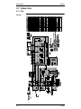
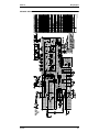
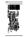
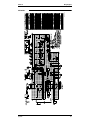
Row×Stages×Fin Pitch
Face Area
Model
Comp.
Type
Motor Output
Model
Type
Fan
Motor Output
Air Flow Rate
Machine Weight
Liquid
Piping
Connections Gas
Drain
Safety Devices
Capacity Control
Refrigerant Control
Max. Length
Ref.Piping
Max. Height Difference
Model
Refrigerant
Charge
Model
Ref. Oil
Charge
Drawing No.
Notes:
mm
m²
kW
W
m³/min.
kg
mm
mm
mm
m
m
kg
L
1. Nominal capacities are based on the following conditions:
Cooling
Heating
Conversion Formulae
Piping length
Hz-Volts
Indoor: 27˚CDB, 19.0˚CWB
Indoor: 20˚CDB, 15˚CWB
7.5m
50Hz~230V
Outdoor: 35˚CDB, 24˚CWB
Outdoor: 7˚CDB, 6˚CWB
(Horizontal)
2. AFR(Air flow rate) is shown at 220V~240V.
3. Capacities are net, including a deduction for cooling (an addition for heating) for indoor fan motor heat.
4. In case of drain piping for outdoor unit, drain piping kit (option) is needed.
Specifications
kcal/h=kW×860
Btu/h=kW×3414
cfm=m³/min×35.3
17
Specifications
1.2
SiE25-110
60Hz
FHYCP (Ceiling Mounted Cassette Type)
Model
Indoor Units
Outdoor Units
kW
1 Cooling Capacity (1)/(2)
Btu/h
kcal/h
kW
1 Heating Capacity (1)/(2)
Btu/h
kcal/h
Indoor Units
Dimensions
Coil
Fan
H×W×D
Type
Row×Stages×Fin Pitch
Face Area
Model
Type
Motor Output
Air Flow Rate
mm
m²
W
m³/min.
Air Filter
Machine Weight
Piping
Connections
kg
mm
mm
mm
Liquid
Gas
Drain
Remote Controller
(Option)
Wired
Wireless
Model
Color
Decoration
Panel (Option) Dimensions (H×W×D)
Air Filter
Weight
Outdoor Units
Color
Dimensions
H×W×D
Type
Coil
Row×Stages×Fin Pitch
Face Area
Model
Comp.
Type
Motor Output
Model
Type
Fan
Motor Output
Air Flow Rate
Machine Weight
Liquid
Piping
Gas
Connections
Drain
Safety Devices
Capacity Control
Refrigerant Control
Max. Length
Ref.Piping
Max. Height Difference
Model
Refrigerant
Charge
Model
Ref. Oil
Charge
Drawing No.
Notes:
mm
kg
mm
m²
kW
W
m³/min.
kg
mm
mm
mm
m
m
kg
L
FHYCP71DVL
FHYCP100DVL
RZP71DVAL
RZP100DVAL
7.1 / 7.2
10.0 / 10.1
(3.3~8.1) / (3.4~8.2)
(5.0~11.4) / (5.1~11.6)
24,200 / 24,500
34,100 / 34,400
(11,200~27,600) / (11,600~27,900)
(17,000~38,900) / (17,400~39,600)
6,100 / 6,100
8,600 / 8,600
(2,800~6,900) / (2,900~7,000)
(4,300~9,800) / (4,300~9,900)
8.0 / 8.0
11.2 / 11.2
(3.5~9.0) / (3.5~9.0)
(5.6~12.8) / (5.6~12.8)
27,300 / 27,300
38,200 / 38,200
(11,900~30,700) / (11,900~30,700)
(19,100~43,600) / (19,100~43,600)
6,800 / 6,800
9,600 / 9,600
(3,000~7,700) / (3,000~7,700)
(4,800~11,000) / (4,800~11,000)
FHYCP71DVL
FHYCP100DVL
246×840×840
288×840×840
Cross Fin Coil (Waffle Louver Fins and N-hix Tubes)
2×10×1.2
2×12×1.2
0.454
0.544
QTS46D14M
QTS46C17M
Turbo Fan
Turbo Fan
30
120
(H) 19 (L) 14
(H) 26 (L) 21
—
—
24
28
φ9.5 (Flare)
φ9.5 (Flare)
φ15.9 (Flare)
φ19.1 (Flare)
I. Dφ25×O. Dφ32
I. Dφ25×O. Dφ32
BRC1C61
BRC1C61
BRC7E61W
BRC7E61W
BYCP125D-W1
BYCP125D-W1
White
White
45×950×950
45×950×950
Resin Net (with Mold Resistant)
Resin Net (with Mold Resistant)
5.5
5.5
RZP71DVAL
RZP100DVAL
Pale Ivory
Pale Ivory
905×900×320
1,435×900×320
Cross Fin Coil (Waffle Fins and NHi-XA Tubes)
2×40×1.4
2×64×1.4
0.991
1.598
2YC63AXD
JT100FA-VD
Hermetically Sealed Swing Type
Hermetically Sealed Scroll Type
1.9
1.9
P47M11F
P47M11F×2
Propeller
Propeller
55
55+55
53
97
71
119
φ9.5 (Flare)
φ9.5 (Flare)
φ15.9 (Flare)
φ19.1 (Flare)
φ26.0 (Hole)
φ26.0 (Hole)
High Pressure Switch. Fuse.
Compressor Revolution Speed Control (Inverter System)
Expansion Valve (Electronic Type)
50 (Equivalent Length 70m)
70 (Equivalent Length 90m)
30
30
R-407C
R-407C
3.2 (Charged for 30m)
5.0 (Charged for 30m)
DAPHNE FVC50K
DAPHNE FVC68D
0.65
1.2
4D034046
1. Nominal capacities are based on the following conditions:
Conversion Formulae
Mark
Cooling
Heating
Piping length
(1)
Indoor: 27˚CDB, 19.0˚CWB
Outdoor: 35˚CDB, 24˚CWB
Indoor: 20˚CDB, 15˚CWB
Outdoor: 7˚CDB, 6˚CWB
7.5m
(Horizontal)
kcal/h=kW×860
Btu/h=kW×3414
cfm=m³/min×35.3
Indoor: 27˚CDB, 19.5˚CWB
Indoor: 21˚CDB, 15˚CWB
5m
Outdoor: 35˚CDB, 24˚CWB
Outdoor: 7˚CDB, 6˚CWB
(Horizontal)
2. Capacities are net, including a deduction for cooling (an addition for heating) for indoor fan motor heat.
3. In case of drain piping for outdoor unit, drain piping kit (option) is needed.
(2)
18
Specifications
SiE25-110
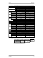
Specifications
FHYCP (Ceiling Mounted Cassette Type)
Model
Indoor Units
Outdoor Units
kW
1 Cooling Capacity (1)/(2)
Btu/h
kcal/h
kW
1 Heating Capacity (1)/(2)
Btu/h
kcal/h
Indoor Units
Dimensions
Coil
Fan
H×W×D
Type
Row×Stages×Fin Pitch
Face Area
Model
Type
Motor Output
Air Flow Rate
mm
m²
W
m³/min.
Air Filter
Machine Weight
Piping
Connections
kg
mm
mm
mm
Liquid
Gas
Drain
Remote Controller
(Option)
Wired
Wireless
Model
Color
Decoration
Panel (Option) Dimensions (H×W×D)
Air Filter
Weight
Outdoor Units
Color
Dimensions
H×W×D
Type
Coil
Row×Stages×Fin Pitch
Face Area
Model
Comp.
Type
Motor Output
Model
Type
Fan
Motor Output
Air Flow Rate
Machine Weight
Liquid
Piping
Gas
Connections
Drain
Safety Devices
Capacity Control
Refrigerant Control
Max. Length
Ref.Piping
Max. Height Difference
Model
Refrigerant
Charge
Model
Ref. Oil
Charge
Drawing No.
Notes:
mm
kg
mm
m²
kW
W
m³/min.
kg
mm
mm
mm
m
m
kg
L
FHYCP125DVL
FHYCP140DVL
RZP125DTAL
RZP140DTAL
12.5 / 12.7
14.0 / 14.2
(6.0~14.3) / (6.1~14.5)
(6.2~15.8) / (6.3~16.1)
42,600 / 43,300
47,700 / 48,400
(20,400~48,800) / (20,800~49,500)
(21,100~53,900) / (21,500~54,900)
10,700 / 10,900
12,000 / 12,200
(5,100~12,200) / (5,200~12,400)
(5,300~13,500) / (5,400~13,800)
14.0 / 14.0
16.0 / 16.0
(6.0~16.2) / (6.0~16.2)
(6.2~18.1) / (6.2~18.1)
47,700 / 47,700
54,600 / 54,600
(20,400~55,300) / (20,400~55,300)
(21,100~61,700) / (21,100~61,700)
12,000 / 12,000
13,700 / 13,700
(5,100~13,900) / (5,100~13,900)
(5,300~15,500) / (5,300~15,500)
FHYCP125DVL
FHYCP140DVL
288×840×840
288×840×840
Cross Fin Coil (Waffle Louver Fins and N-hix Tubes)
2×12×1.2
2×12×1.2
0.544
0.544
QTS46C17M
QTS46C17M
Turbo Fan
Turbo Fan
120
120
(H) 30 (L) 24
(H) 33 (L) 25
—
—
28
28
φ9.5 (Flare)
φ9.5 (Flare)
φ19.1 (Flare)
φ19.1 (Flare)
I. Dφ25×O. Dφ32
I. Dφ25×O. Dφ32
BRC1C61
BRC1C61
BRC7E61W
BRC7E61W
BYCP125D-W1
BYCP125D-W1
White
White
45×950×950
45×950×950
Resin Net (with Mold Resistant)
Resin Net (with Mold Resistant)
5.5
5.5
RZP125DTAL
RZP140DTAL
Pale Ivory
Pale Ivory
1,435×900×320
1,435×900×320
Cross Fin Coil (Waffle Fins and NHi-XA Tubes)
2×64×1.4
2×64×1.4
1.598
1.598
JT100FAVD
JT100FAVD
Hermetically Sealed Scroll Type
2.4
2.9
P47M11F×2
P47M11F×2
Propeller
Propeller
55+55
55+55
102
102
119
119
φ9.5 (Flare)
φ9.5 (Flare)
φ19.1 (Flare)
φ19.1 (Flare)
φ26.0 (Hole)
φ26.0 (Hole)
High Pressure Switch. Fuse.
Compressor Revolution Speed Control (Inverter System)
Expansion Valve (Electronic Type)
70 (Equivalent Length 90m)
70 (Equivalent Length 90m)
30
30
R-407C
R-407C
5.0 (Charged for 30m)
5.0 (Charged for 30m)
DAPHNE FVC68D
DAPHNE FVC68D
1.2
1.2
4D034047
1. Nominal capacities are based on the following conditions:
Conversion Formulae
Mark
Cooling
Heating
Piping length
(1)
Indoor: 27˚CDB, 19.0˚CWB
Outdoor: 35˚CDB, 24˚CWB
Indoor: 20˚CDB, 15˚CWB
Outdoor: 7˚CDB, 6˚CWB
7.5m
(Horizontal)
kcal/h=kW×860
Btu/h=kW×3414
cfm=m³/min×35.3
Indoor: 27˚CDB, 19.5˚CWB
Indoor: 21˚CDB, 15˚CWB
5m
Outdoor: 35˚CDB, 24˚CWB
Outdoor: 7˚CDB, 6˚CWB
(Horizontal)
2. Capacities are net, including a deduction for cooling (an addition for heating) for indoor fan motor heat.
3. In case of drain piping for outdoor unit, drain piping kit (option) is needed.
(2)
Specifications
19
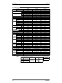
Specifications
1.3
SiE25-110
Comply with Australian Standard (50Hz)
FHYCP (Ceiling Mounted Cassette Type: Pair System)
Model
Indoor Units
Outdoor Units
kW
Btu/h
kcal/h
kW
Btu/h
kcal/h
1 Cooling Capacity
(Min.~Max.)
1 Heating Capacity
(Min.~Max.)
Indoor Units
Dimensions
Coil
Fan
H×W×D
Type
Row×Stages×Fin Pitch
Face Area
Model
Type
Motor Output
Air Flow Rate
Air Filter
Machine Weight
Piping
Connections
W
m³/min.
Wired
Wireless
Model
Color
Decoration
Panel (Option) Dimensions (H×W×D)
Air Filter
Weight
Outdoor Units
Color
Dimensions
H×W×D
Type
Coil
Row×Stages×Fin Pitch
Face Area
Model
Comp.
Type
Motor Output
Model
Type
Fan
Motor Output
Air Flow Rate
Machine Weight
Liquid
Piping
Gas
Connections
Drain
Safety Devices
Capacity Control
Refrigerant Control
Max. Length
Ref. Piping
Max. Height Difference
Model
Refrigerant
Charge
Model
Ref. Oil
Charge
Drawing No.
Notes:
m²
kg
mm
mm
mm
Liquid
Gas
Drain
Remote Controller
(Option)
mm
mm
kg
mm
m²
kW
W
m³/min.
kg
mm
mm
mm
m
m
kg
L
FHYCP71DVE
RZP71DV1
6.9 (3.2~7.8)
23,500 (10,900~26,600)
5,900 (2,700~6,700)
7.8 (3.4~8.8)
26,600 (11,600~30,000)
6,700 (2,900~7,500)
FHYCP71DVE
246×840×840
FHYCP100DVE
FHYCP125DVE
RZP100DV1
RZP125DV1
9.7 (4.9~11.0)
12.1 (5.8~13.8)
33,100 (16,700~37,500)
41,300 (19,800~47,100)
8,300 (4,200~9,400)
10,400 (4,900~11,800)
11.0 (5.5~12.6)
13.7 (5.9~15.9)
37,500 (18,700~43,000)
46,700 (20,100~54,200)
9,400 (4,700~10,800)
11,700 (5,000~13,600)
FHYCP100DVE
FHYCP125DVE
288×840×840
288×840×840
Cross Fin Coil (Multi Louver Fins and N-hix Tubes)
2×10×1.2
2×12×1.2
2×12×1.2
0.454
0.544
0.544
QTS46D14M
QTS46C17M
QTS46C17M
Turbo Fan
Turbo Fan
Turbo Fan
30
120
120
(H) 19 (L) 14
(H) 26 (L) 21
(H) 30 (L) 24
—
—
—
24
28
28
φ9.5 (Flare)
φ9.5 (Flare)
φ9.5 (Flare)
φ15.9 (Flare)
φ19.1 (Flare)
φ19.1 (Flare)
I. Dφ25×O. Dφ32
I. Dφ25×O. Dφ32
I. Dφ25×O. Dφ32
BRC1C61
BRC1C61
BRC1C61
BRC7E61W
BRC7E61W
BRC7E61W
BYCP125D-W1
BYCP125D-W1
BYCP125D-W1
White
White
White
45×950×950
45×950×950
45×950×950
Resin Net (with Mold Resistant)
Resin Net (with Mold Resistant)
Resin Net (with Mold Resistant)
5.5
5.5
5.5
RZP71DV1
RZP100DV1
RZP125DV1
Pale Ivory
Pale Ivory
Pale Ivory
905×900×320
1,435×900×320
1,435×900×320
Cross Fin Coil (Waffle Fins and NHi-XA Tubes)
2×40×1.4
2×64×1.4
2×64×1.4
0.991
1.598
1.598
2YC63AXD
JT100FAVD
JT100FAVD
Hermetically Sealed Swing Type
Hermetically Sealed Scroll type
1.9
1.9
2.4
P47M11F
P47M11F×2
P47M11F×2
Propeller
Propeller
Propeller
55
55+55
55+55
53
97
102
71
119
119
φ9.5 (Flare)
φ9.5 (Flare)
φ9.5 (Flare)
φ15.9 (Flare)
φ19.1 (Flare)
φ19.1 (Flare)
φ26.0 (Hole)
φ26.0 (Hole)
φ26.0 (Hole)
High Pressure Switch. Fuse.
Compressor Revolution Speed Control (Inverter System)
Expansion Valve (Electronic Type)
50 (Equivalent Length 70m)
70 (Equivalent Length 90m)
70 (Equivalent Length 90m)
30
30
30
R-407C
R-407C
R-407C
3.2 (Charged for 30m)
5.0 (Charged for 30m)
5.0 (Charged for 30m)
DAPHNE FVC50K
DAPHNE FVC68D
DAPHNE FVC68D
0.65
1.20
1.20
4D034232
1. Nominal capacities are based on the following conditions:
Cooling
Heating
Conversion Formulae
Piping length
Hz-Volts
Indoor: 27˚CDB, 19.0˚CWB
Indoor: 20˚CDB, 15˚CWB
7.5m
Outdoor: 35˚CDB, 24˚CWB
Outdoor: 7˚CDB, 6˚CWB
(Horizontal) 50Hz-240V
2. Capacities are net, including a deduction for cooling (an addition for heating) for indoor fan motor heat.
3. In case of drain piping for outdoor unit, drain piping kit (option) is needed.
20
kcal/h=kW×860
Btu/h=kW×3414
cfm=m³/min×35.3
Specifications
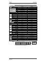
SiE25-110
Specifications
FHYCP (Ceiling Mounted Cassette Type: Twin System)
Model
Indoor Units
Outdoor Units
kW
Btu/h
kcal/h
kW
Btu/h
kcal/h
1 Cooling Capacity
(Min.~Max.)
1 Heating Capacity
(Min.~Max.)
Indoor Units
Dimensions
Coil
Fan
H×W×D
Type
Row×Stages×Fin Pitch
Face Area
Model
Type
Motor Output
Air Flow Rate
Air Filter
Machine Weight
Piping
Connections
m²
W
m³/min.
Wired
Wireless
Model
Color
Decoration
Panel (Option) Dimensions (H×W×D)
Air Filter
Weight
Outdoor Units
Color
Dimensions
H×W×D
Type
Coil
Row×Stages×Fin Pitch
Face Area
Model
Comp.
Type
Motor Output
Model
Type
Fan
Motor Output
Air Flow Rate
Machine Weight
Liquid
Piping
Gas
Connections
Drain
Safety Devices
Capacity Control
Refrigerant Control
Max. Length
Ref. Piping
Max. Height Difference
Model
Refrigerant
Charge
Model
Ref. Oil
Charge
Drawing No.
Notes:
mm
kg
mm
mm
mm
Liquid
Gas
Drain
Remote Controller
(Option)
FHYCP50DVE×2
FHYCP60DVE×2
RZP100DV1
RZP125DV1
9.7 (4.9~11.0)
12.1 (5.8~13.8)
33,100 (16,700~37,500)
41,300 (19,800~47,100)
8,300 (4,200~9,400)
10,400 (4,900~11,800)
11.0 (5.5~12.6)
13.7 (5.9~15.9)
37,500 (18,700~43,000)
46,700 (20,100~54,200)
9,400 (4,700~10,800)
11,700 (5,000~13,600)
FHYCP50DVE×2
FHYCP60DVE×2
246×840×840
246×840×840
Cross Fin Coil (Multi Louver Fins and N-hix Tubes)
2×8×1.2
2×10×1.2
0.363
0.454
QTS46D14M
QTS46D14M
Turbo Fan
30
30
(H) 16 (L) 11
(H) 17 (L) 13
—
Resin Net (with Mold Resistant)
23
24
φ9.5 (Flare)
φ9.5 (Flare)
φ15.9 (Flare)
φ15.9 (Flare)
I. Dφ25×O. Dφ32
I. Dφ25×O. Dφ32
BRC1C61
BRC1C61
BRC7E61W
BRC7E61W
BYCP125D-W1
BYCP125D-W1
White
White
45×950×950
45×950×950
Resin Net (with Mold Resistant)
Resin Net (with Mold Resistant)
5.5
5.5
RZP100DV1
RZP125DV1
Pale Ivory
Pale Ivory
1,435×900×320
1,435×900×320
Cross Fin Coil (Waffle Fins and NHi-XA Tubes)
2×64×1.4
2×64×1.4
1.598
1.598
JT100FAVD
JT100FAVD
Hermetically Sealed Scroll type
1.9
2.4
P47M11F×2
P47M11F×2
Propeller
Propeller
55+55
55+55
97
102
119
119
φ9.5 (Flare)
φ9.5 (Flare)
φ19.1 (Flare)
φ19.1 (Flare)
φ26.0 (Hole)
φ26.0 (Hole)
High Pressure Switch. Fuse.
Compressor Revolution Speed Control (Inverter System)
Expansion Valve (Electronic Type)
70 (Equivalent Length 90m)
70 (Equivalent Length 90m)
30
30
R-407C
R-407C
5.0 (Charged for 30m)
5.0 (Charged for 30m)
DAPHNE FVC68D
DAPHNE FVC68D
1.20
1.20
4D034231
mm
kg
mm
m²
kW
W
m³/min.
kg
mm
mm
mm
m
m
kg
L
1. Nominal capacities are based on the following conditions:
Cooling
Heating
Conversion Formulae
Piping length
Hz-Volts
Indoor: 27˚CDB, 19.0˚CWB
Indoor: 20˚CDB, 15˚CWB
7.5m
Outdoor: 35˚CDB, 24˚CWB
Outdoor: 7˚CDB, 6˚CWB
(Horizontal) 50Hz~240V
2. Capacities are net, including a deduction for cooling (an addition for heating) for indoor fan motor heat.
3. In case of drain piping for outdoor unit, drain piping kit (option) is needed.
Specifications
kcal/h=kW×860
Btu/h=kW×3414
cfm=m³/min×35.3
21
Specifications
22
SiE25-110
Specifications
SiE25-110
Part 4
Remote Controller
1. Wired Remote Controller.......................................................................24
1.1 Wired Remote Controller - NEW MODEL
(For Cooling only and heat-pump Model) .............................................. 24
1.2 Installation ............................................................................................. 26
2. Wireless Remote Controller ..................................................................28
2.1 Wireless Remote Controller................................................................... 28
Remote Controller
23
Wired Remote Controller
SiE25-110
1. Wired Remote Controller
1.1
Wired Remote Controller - NEW MODEL
(For Cooling only and heat-pump Model)
BRC1C61
FHYCP, FHYP, FUYP, FAYP
BRC1C61
New
BRC1C61
BRC1B61
ON / OFF Operation with Air
Conditioner
Independent operation in
intermediate season
Ventilation mode change over
(Auto / HRV / Normal)
Air flow change over
(Auto / High / Low)
Setting of precooling / preheating
Setting of fresh-up operation
Filter sign display
: Initial Setting Only (Field setting by well known service
person)
5 12
4
2
1
3
7
hr
C
hr
6
8
NOT
AVAILABLE
TEST
L H
14
9
11
10
13
21
20
TEST
16
19
15
17
18
22
3PA59583-16Z-1
24
Remote Controller
SiE25-110
1
2
3
4
Wired Remote Controller
ON/OFF BUTTON
Press the button and the system will start.
Press the button again and the system will
stop.
OPERATION LAMP (RED)
The lamp lights up during operation.
DISPLAY “
” (UNDER CENTRALIZED CONTROL)
When this display shows, the system is
UNDER
CENTRALIZED CONTROL.
DISPLAY “
” “
”“
”“
”
(VENTILATION/AIR CLEANING)
This display shows that the total heat
exchange and the air cleaning unit are in
operation (These are optional
accessories).
5
DISPLAY “ ” “ ” “ ” “ ” “ ”
(OPERATION MODE)
This display shows the current OPERATION
MODE. For cooling only type, “
” (Auto)
and “ ” (Heating) are not installed.
6
DISPLAY “
TEST” (INSPECTION/TEST
OPERATION)
When the INSPECTION/TEST OPERATION
BUTTON is pressed, the display shows the
system mode is in.
hr
DISPLAY “
14
15
TIMER MODE START/STOP BUTTON
TIMER ON/OFF BUTTON
INSPECTION/TEST OPERATION BUTTON
16 This button is used only by qualified service
persons for maintenance purposes.
PROGRAMMING TIME BUTTON
17 Use this button for programming “START and/
or STOP” time.
TEMPERATURE SETTING BUTTON
18
Use this button for SETTING TEMPERATURE.
FILTER SIGN RESET BUTTON
19
FAN SPEED CONTROL BUTTON
20 Press this button to select the fan speed,
HIGH or LOW, of your choice.
OPERATION MODE SELECTOR BUTTON
21
Press this button to select OPERATION MODE.
AIR FLOW DIRECTION ADJUST BUTTON
22
NOTE
• For the sake of explanation, all indications are
shown on the display in Figure 1 contrary to
actual running situations.
” (PROGRAMMED TIME)
hr
7
This display shows the PROGRAMMED TIME
of the system start or stop.
8
DISPLAY “
” (SET TEMPERATURE)
This display shows the set temperature.
9
DISPLAY “
” (FAN SPEED)
This display shows the set fan speed.
C
DISPLAY “
” (AIR FLOW FLAP)
10
DISPLAY “
11 TER)
12
DISPLAY “
” (TIME TO CLEAN AIR FIL-
” (DEFROST)
NON-FUNCTIONING DISPLAY
If that particular function is not available, pressing the button may display the words “NOT
AVAILABLE” for a few seconds.
13 When running multiple units simultaneously
The “NOT AVAILABLE” message will only be
appear if none of the indoor units is equipped
with the function. If even one unit is equipped
with the function, the display will not appear.
Remote Controller
3PA59583-16Z-2
25
Wired Remote Controller
1.2
26
SiE25-110
Installation
Remote Controller
SiE25-110
Remote Controller
Wired Remote Controller
27
Wireless Remote Controller
SiE25-110
2. Wireless Remote Controller
2.1
Wireless Remote Controller
Names and Function
Name of Option
Remote Controller
Model Series
FHYP
FUYP
BRC7E63W
BRC7C528W
FHYCP
BRC7E61W
FAYP
BRC7C610W
1-1
1
ON OFF
3
8
1-2
H
M L
DOWN
10
C
ON OFF
UP
6
TEMP
FAN
H
M L TIME
4
hr.
2
11
C
UP
9
hr.
DOWN
FAN
13
RESERVE CANCEL
hr.
5
TIMER
12
MODE
15
hr.
TEST
7
SWING
14
16
TEST
TEST
17
3PA63363-21T-1
Explanation of Receiver
FHYCP
FAYP
21
20
19
18
23
FUYP
22
FHYP
22
19
21 20
23
18
3PA63363-21T-2
28
Remote Controller
SiE25-110
Wireless Remote Controller
DISPLAY “
” (SIGNAL
TRANSMISSION)
1
This lights up when a signal is being
transmitted.
DISPLAY “ ” “ ” “
”“
“ ” (OPERATION MODE)
3
4
H
M L
C
” (SET TEMPERATURE)
6
7
8
9
10
11
12
AIR FLOW DIRECTION ADJUST
14 BUTTON
15
16
This display shows the set temperature.
hr.
DISPLAY “ hr.
”
(PROGRAMMED TIME)
This display shows PROGRAMMED
TIME of the system start or stop.
5
DISPLAY “
TIMER RESERVE/CANCEL BUTTON
”
2 This display shows the current OPERATION MODE. For straight cooling
type, “
” (Auto) and “ ” (Heating)
are not installed.
DISPLAY “
13
17
18
” (AIR FLOW FLAP)
DISPLAY “
”“
” (FAN SPEED)
The display shows the set fan speed.
TEST ”
DISPLAY “
(INSPECTION/ TEST OPERATION)
When the INSPECTION/TEST OPERATION BUTTON is pressed, the display
shows the system mode is in.
ON/OFF BUTTON
Press the button and the system will
start. Press the button again and the
system will stop.
FAN SPEED CONTROL BUTTON
Press this button to select the fan
speed, HIGH or LOW, of your choice.
TEMPERATURE SETTING BUTTON
Use this button for SETTING TEMPERATURE (Operates with the front cover
of the remote controller closed.)
PROGRAMMING TIMER BUTTON
Use this button for programming
“START and/or STOP” time. (Operates
with the front cover of the remote controller opened.)
TIMER MODE START/STOP BUTTON
19
20
21
22
23
OPERATION MODE SELECTOR
BUTTON
Press this button to select OPERATION
MODE.
FILTER SIGN RESET BUTTON
Refer to the section of MAINTENANCE
in the operation manual attached to the
indoor unit.
INSPECTION/TEST OPERATION
BUTTON
This button is used only by qualified
service persons for maintenance
purposes.
EMERGENCY OPERATION SWITCH
This switch is readily used if the remote
controller does not work.
RECEIVER
This receives the signals from the
remote controller.
OPERATING INDICATOR LAMP
(Red)
This lamp stays lit while the air
conditioner runs. It flashes when the
unit is in trouble.
TIMER INDICATOR LAMP (Green)
This lamp stays lit while the timer is set.
AIR FILTER CLEANING TIME
INDICATOR LAMP (Red)
Lights up when it is time to clean the air
filter.
DEFROST LAMP (Orange)
Lights up when the defrosting operation has started. (For straight cooling
type this lamp does not turn on.)
3PA63363-21T-3
Remote Controller
29
Wireless Remote Controller
30
SiE25-110
Remote Controller
SiE25-110
Part 5
Field Piping and Wiring
1. Field Piping and Wiring .........................................................................32
1.1 Precautions............................................................................................ 32
1.2 Field Piping............................................................................................ 35
1.3 Field Wiring............................................................................................ 37
Field Piping and Wiring
31
Field Piping and Wiring
SiE25-110
1. Field Piping and Wiring
1.1
Precautions
Caution to be Taken When Brazing Refrigerant Piping
“Do not use flux when brazing copper-to-copper refrigerant piping. (Particularly for the HFC
refrigerant piping) Therefore, use the phosphor copper brazing filler metal (BCuP) which does
not require flux.”
(Flux has extremely harmful influence on refrigerant piping systems. For instance, if the chlorine
based flux is used, it will cause pipe corrosion or, in particular, if the flux contains fluorine, it will
damage the refrigerant oil. The use of flux is strictly forbidden since the cleaning on site is
impossible.)
(Caution) Keep in mind that if the phosphor copper brazing filler metal is used and the
brazing temperature and the heating time exceed a certain point, the phosphor
changes into the gaseous state (e.g. BCuP -1 to 5 : between 700 and 800C) which
causes pin holes and results in refrigerant leakage.
R-407C applies higher pressure than R-22 and uses
refrigeration oil different from R-22. Therefore, piping
Refrigerant
works and tools are also different from those for R-22
refrigerants.
Refrigeration oil
R-22
R-407C
(Single-component refrigerant)
(Multiple-component refrigerant)
Condensing pressure
Mineral oil (Suniso)
Synthetic (ether) oil
1.84MPa (18.8kg/cm2)
2.01MPa (20.5kg/cm2)
Refrigerant Piping Materials
Other refrigerant piping materials
Use C1220 type copper tube for refrigerant piping. Wall thickness
of copper tube shown in the below table can be applied.
(The table is same as the recommendation for R-22)
Recommendable oil for pipe processing
DAPHNE MASTER DRAW 510LS·530LS·565NR·566LS (Idemitsu Kosan Co.,Ltd.)
MASTER DRAW 5128 (ETNA PRODUCTS INC.)
Shell Drawing XA (SHELL)
* Mixing amount of oil is 30 mg/10m at maximum.
(Unit : mm)
Type
O type
Copper tube O.D.
9.5
15.9
19.1
Copper tube W.T.
0.8
1.0
1.0
* When select and use a copper tube, observe strictly the relevant standards or regulations of each country.
32
(As of March 2001)
Field Piping and Wiring
SiE25-110
Field Piping and Wiring
Procedure and Tools for Refrigerant Piping Work
Procedure
Piping work for R-407C model partially differs from R-22 model in items and procedures of piping work and refrigerant charging due to
different component and higher pressure for R-407C. The below chart shows general work procedure for R-407C model.
Determination of work item
Prior to work
Confirm the refrigerant is R-407C or R-22
Check the refrigerant to be used
Preparing of working drawing
Mounting sleeves and inserts
Installing indoor unit
Refrigerant piping work
(1) Check wall thickness of copper tube (Refer to the table "Wall
thickness of refrigerant pipe")
(2) Maintain cleanliness inside of pipe.
(3) Make sure to conduct N2 blowing when brazing is required.
(4) Pay attention on pipe flaring and oil to be coated on flared section.
(5) Be sure to use torque wrench.
Drain piping work
Duct work
Insulation work
(1) Make sure to conduct air tight test.
(2) Confirm the pressure of 3.2 MPa does not decrease for 24 hours.
(In case the design pressure of 3.2 MPa)
Electric work (Connection wiring / Power supply)
Setting various items
Work
Foundation work for outdoor unit
(1) Vacuum grade is -755 mmHg or lower
(2) Use dedicated vacuum pump
Installation of outdoor unit
Air tight test
Vacuum drying
Refrigerant additional charging
(1) Confirm the correct amount of refrigerant.
(2) Be sure to charge refrigerant in liquid phase.
(3) Use the dedicated gauge manifold and charging hose.
(4) The refrigerant amount to be charged is shown in the installation manual.
(5) Record the added refrigerant amount to the record sheet.
Test run / Adjustment
Preparing documents required before delivery
Delivery / Operation instruction
Field Piping and Wiring
Preparation of documents and drawings in accordance with local
codes and standard.
33
Field Piping and Wiring
SiE25-110
Tools
Several dedicated tools are required for the installation work of R-407C models. Some of conventional tools can be used except tools
actually used to the installation work for R-22 models.
Tool name
Work process / Usage
Pipe cutter
Pipe cutting
Flaring tool
Pipe flaring
Refrigeration oil
Torque wrench
Refrigerant
piping work
Applying to flared section
Pipe expanding in connection of pipe
Pipe bender
Pipe bending
Nitrogen
Oxidation proof for inside pipe
Air tight test
Gauge manifold
Use dedicated ether oil, ester oil, alkyl-benzene oil or mixture of those oil.
Interchangeable and can be used.
Pipe brazing
Charging hose
From air tight test
Refrigerant charging using
to refrigerant
vacuum and operation check
additional charging
Vacuum pump
Vacuum drying
Dedicated gauge is required due to high pressure.
For preventing refrigerant leakage and mixing of foreign matters,
dedicated charging hose is required.
Interchangeable and can be used. (Be strictly sure that oil does
not flow in reverse to the unit during pump stop.)
Charging cylinder
Weighing scale for
refrigerant charging
Interchangeable and can be used.
Flare nut jointing
Pipe expander
Welder
Interchangeability with conventional tool
Not required since charging work conducted with weighing scale.
Refrigerant additional charging
Gas leakage detector
Gas leakage check
Interchangeable and can be used.
Dedicated detector is required (Detector for R134a can be used).
Precautions for Installation Work
Joint brazing
Since stricter caution should be necessary for R-407C to
prevent intrusion of foreign matters into the refrigerant piping
line, be sure to conduct N2 blowing when brazing is required.
Other than brazing, a stricter work control including pipe
covering and drying is required to prevent pipe from intrusion of
foreign matters.
Flaring
Make sure to conduct chamfering (filing) at cut section, since a
large wall thickness of pipe results large burr. Be aware of no
cutting chips left inside pipe.
Refrigerant charging
Charge R-407C from service port at liquid side stop value of
outdoor unit in liquid phase. At that time, conduct vacuum
drying using vacuum pump.
Apply appropriate amount of refrigeration oil on outer / inner
surface of flared section to prevent leakage. Make sure to
use synthetic oil (ether oil, ester oil, archi-benzene oil or
mixture of those oils) as refrigeration oil.
Air-tightness test
Make sure to conduct air-tightness test.
Conduct installation work for R-407C model following above mentioned piping work procedure. Otherwise, unit
may have trouble. Refer to the "Work execution and control for R-407C model" for the details on handling of R-407C,
installation works and tools.
34
Field Piping and Wiring
SiE25-110
1.2
Field Piping and Wiring
Field Piping
This unit requires additional charging of refrigerant according to the length of pipe connected at the site.
When the entire refrigerant pipe length is within 30 meters, the additional changing is not needed.
Take the following steps for proper charging.
When connected to indoor units
When connected to two indoor units
Branched pipe
(L2)
One way length of pipe (L)
Branched pipe (L3)
Main pipe (L1)
One-way length of pipe (L) : L1+L2+L3
(1) Additional charging of refrigerant
Select the appropriate refrigerant charging amout from Table 2, 3 and charge the refrigerant. Fill out the
notice plate attached in the rear of the front plate (2) for future servicing.
• Pair-type
Table 1 Additional charging refrigerant amount
(unit: kg)
Pipe excess length over 30 meters
20m or less
40m or less
71, 100, 125, 140 type
0.8
1.6
Simultaneous operation multi-type
• Find the entire pipe length by totaling that of each pipe in the order of the main pipe (L1), and branched
pipes (L2), (L3) calculate the excess length going over 30 meters, then select from Table 3 the amount of
refrigerant corresponding to the excess length.
The total value is the amount required for additional charging.
Table 2 Additional charging amount
(unit: kg)
Pipe excess length over 30 meters
Liquid pipe
9.5
10m or less
20m or less
30m or less
40m or less
0.4
0.8
1.2
1.6
(2) Complete charging of the refrigerant
When the entire refrigerant pipe length is within 30 meters, charge the refrigerant in accordance with the
amount mentioned in the nameplate, and when the pipe length exceeds 30 meters, the charging amount
mentioned in the nameplate and that required for additional charging are to be totaled as the net charging
amount.
*Vacuum drying when refilling the refrigerant will not be sufficient if done only at the shut-off valve service
port (gas and liquid sides), so it should be done from a service port set up on the pipe leading from the outdoor unit 4-path switch valve to the heat exchanger.
(S2535)
Field Piping and Wiring
35
Field Piping and Wiring
SiE25-110
(4) Precautions for pumping-down operation
(When moving and remounting the indoor or outdoor units, etc.)
When running pump-down operation, turn off the power and protect the terminal block to prevent it
from coming into contact with the insulating sheet, as shown in the figure.
Switch box
Terminal block
Top plate
71 TYPE
Pump-down
push switch
100, 125, 140
TYPE
Pump-down
push switch
BS1
BS1
BS1
PC-board (A3P)
Vinyl or other insulation sheet
(secure with tape)
Figure of front side of outdoor unit (PC-board (A3P) vicinity)
Pressing the pump-down push switch on the outdoor PC-board (A3P) may cause the indoor fan to
automatically start spinning, so use caution.
Turn on the power and enter pump-down operation using the following procedure.
1
Procedure
Precautions
Start fan operation with the
remote controller.
Confirm that stop valves both on
the liquid and gas side are open.
Take care when the procedure 2
is done first because the indoor
unit fan may operate automatically.
(Liquid pipe) (Gas pipe)
Closing direction
Push the pumping down butCompressor and outdoor fan will
2 ton on the PC board of the outstart operation automatically.
door unit.
3
Once operation stops after about 3 or 5 minutes, close the shutoff valves for the gas and liquid sides. (Refer to Fig. 11)
Fig. 11
This is the end of pumping-down operation. After pumping-down operation, the remote controller shows “U4” even when ON button on the remote controller is pressed, and it will
not operate. Turn off the main power supply switch and turn it on again in need of operation.
To all persons doing pipe work.
Be sure to open the shut-off valve after finishing pipe work. (Operating the unit with it closed will cause the
compressor to break.)
(S2536)
36
Field Piping and Wiring
SiE25-110
Field Piping and Wiring
Necessity of a trap
Since there is fear of the oil held inside the riser piping flowing back into the compressor when
stopped and causing liquid compression phenomenon, or cases of deterioration of oil return, it
will be necessary to provide a trap at an appropriate place in the riser gas piping.
Trap installation spacing
Indoor unit
Oil trap
Gas piping
*15m
Liquid piping
*Marks. Install trap at
each difference in
height 15m
Outdoor unit
Note:
1.3
(S2534)
A trap is not necessary when the outdoor unit is installed in a higher position than the indoor
unit.
Field Wiring
Field Piping and Wiring
37
Field Piping and Wiring
SiE25-110
WARNING
Electrical wiring must be carried out by qualified personnel.
Before obtainging access to terminal devices, all supply circuits munt be interrupted.
CAUTION
Be sure to ground the air conditioner.
Do not connect the earth wire to a gas pipe, water pipe, lightning conductor or telephone earth wire.
Use only copper wires.
The wiring between the indoor unit and outdoor unit must be for 220V.
Do not turn on the main switch until all the wiring is complated.
The resistance of the grounding must not exceed 500 .
When performing electrical wiring, refer also to the wiring diagram affixed to the unit.
Use the specified wires and fix them with clamps so that no external forces act on the terminals. For clamping, push the hook in tail end of the clamp to loosen it, pass the wires through it, then fasten the clamp.
Clamp the wiring as shown below, taking care that the wires do not touch the piping. (especially high-pressure piping)
Never squeeze extra wires into the unit.
When leading out the wires to the front or side, you can use a wire conduit passing through the knock-out
hole ( 34mm). When you don’t use a wire conduit, be sure to protect the wires with vinyl tubes etc. to prevent the edge of the knock-out hole from cutting the wires.
Form the wires and fix the cover firmly so that the cover may be fit in properly.
Wiring between units
Note: The service ports and the four-way switch
valve have been covered by insulation
tubing in order to protect wiring from high
temperatures. Do not remove this tubing
for any reason other than for service work.
If it is removed, be sure to replace it and
secure it with the clamping material.
VAL Model
Back
1 23L
N
Power supply
and ground
wiring
Forward
Down
Wiring between
units
To the side
Ground
Switch box
Switch
box
TAL Model
1 2 3RS T
Ground
Insulation tubing
Clamp
(attached)
Clamp
Clamp (attached)
Insulation tubing
Hook
Stop valve
mounting plate
Clamp
Power supply and
ground wiring
Stop valve
mounting plate
Wiring
between
units
When using 71 model
Clamp
Wiring between
units
Power supply and
ground wiring
When using 100 · 125 · 140 model
CAUTIONS
As this unit is equipped with an inverter, installing a phase advancing capacitor not only will deteriorate
power factor improvement effect, but also may cause a capacitor abnomal heating accident due to high-frequency waves. Therefore never install a phase advancing capacitor.
keep power imbalance to within 2% of the supply rating.
1. Large imbalance will shorten the life of the smoothing capacitor.
2. As a protective measure, the product will stop operating and an error indication will be made, when
power imbalance exceeds 4% of the supply rating.
When installing the leakage breaker make sure it is an inverter-type (high-frequency/high-freq. non-sensing
type) breaker.
38
Field Piping and Wiring
SiE25-110
Part 6
Field Setting
1. Method of Field Set
(Reset after Maintenance Inspection/Repair)........................................40
1.1
1.2
1.3
1.4
1.5
1.6
Explanation............................................................................................ 40
Field Setting........................................................................................... 41
Initial Setting Contents........................................................................... 43
Local Setting Mode No. ......................................................................... 44
Detailed Explanation of Setting Modes.................................................. 46
Centralized Group No. Setting............................................................... 52
2. Settings Concerning Maintenance ........................................................53
2.1 Indoor Unit PCB..................................................................................... 53
2.2 Outdoor Unit Switches / Setting Jumper................................................ 57
3. Existence of DIP Switch, Jumper and BS .............................................60
3.1
3.2
3.3
3.4
Field Setting
Reference Table .................................................................................... 60
Initial DIP Switch Setting List (Factory Set) ........................................... 62
Emergency Operation............................................................................ 63
Maintenance Mode Setting.................................................................... 64
39
Method of Field Set (Reset after Maintenance Inspection/Repair)
SiE25-110
1. Method of Field Set
(Reset after Maintenance Inspection/Repair)
1.1
Explanation
Field set is carried out from the remote controller. At time of installation, or after maintenance
inspection/repair, carry out field set according to the explanation below. Incorrect settings will
cause a malfunction to occur. (The indoor unit settings are sometimes changed if optional
accessories are mounted on the indoor unit. Refer to the optional accessory manual.)
40
Field Setting
SiE25-110
1.2
Method of Field Set (Reset after Maintenance Inspection/Repair)
Field Setting
1.2.1 Wired Remote Controller
Notes:
(Field setting must be made from the remote controller in accordance with the installation
conditions.)
Setting can be made by changing the “Mode number”, “FIRST CODE NO.”, and “SECOND
CODE NO.”.
Refer to the following procedures for Field setting.
Procedure
Field Setting
41
Method of Field Set (Reset after Maintenance Inspection/Repair)
SiE25-110
1.2.2 Wireless Remote Controller
Note:
Procedure
42
If optional accessories are mounted on the indoor unit, the indoor unit setting may have to be
changed. Refer to the instruction manual (optional hand book) for each optional accessory.
1. When in the normal mode, push the “
” button for a minimum of four seconds,
and the FIELD SET MODE is entered.
2. Select the desired MODE NO. with the “
” button.
3. Push the “
” button and select the FIRST CODE NO.
4. Push the “
” button and select the SECOND CODE NO.
5. Push the “
” button and the present settings are SET.
6. Push the “
” button to return to the NORMAL MODE.
Field Setting
SiE25-110
1.3
Method of Field Set (Reset after Maintenance Inspection/Repair)
Initial Setting Contents
Setting Contents Filter
Sign
Filter Sign
Estimation of
Accumulated
Operating
Hours
High Air
Outlet
Velocity
(for
Application
to Ceiling
Higher
than 2.7m)
Selection
of Air
Flow
Direction
F, T, W
Air Flow
Direction
Adjust
Air Flow
Direction
Range
Setting
External
Static
Pressure
Long
Life
Filter
Type
Fan
Speed
Up
Simultaneous
operation
(Twin)
Indoor Models
Ceiling
Mounted
Super
Cassette
(FHYCP)
(Heat
Pump)
FHYCP
50~140D
New
Ceiling
Mounted
Suspended
Cassette
(FUYP)
(Heat
Pump)
FUYP
71~125B
Ceiling
(Heat
Suspended Pump)
(FHYP)
FHYP
50~125B
Wall
Mounted
Type
(Heat
Pump)
FAYP
71, 100B
Field Setting
43
Method of Field Set (Reset after Maintenance Inspection/Repair)
1.4
SiE25-110
Local Setting Mode No.
Example
To set the filter sign time to “filter contamination - heavy” for all units in a group:
Set mode No. to “10,” setting switch No. to “0,” and setting position No. to “02.”
Table
Mode Setting
Setting Description
No.
Switch
Note 1
No.
10
0
Filter contamination - heavy / Ultra-Long(20)
light (Setting of operating
Life Type
hours for filter sign indication)
(Change setting when
Long-Life
reducing filter sign indication
Type
time to half due to quick soiling
of filter)
Standard
Type
1
2
3
11
(21)
0
2
12
(22)
13
(23)
4
5
0
1
3
4
6
44
Long-life filter type (Setting of filter sign
indication time)
(Change setting when Ultra-long-life filter is
installed)
Remote control thermostat
(Set when remote control thermostat sensor
is used.)
Estimation of filter operating hour
(Change setting when filter sign indication is
not used)
No. of Sky Air indoor units connected for
simultaneous ON-OFF multi system
(Change setting when simultaneous
operation multi system is used) *Note 3
Indoor unit fan OFF when cooling/heating is
OFF
PMV Control
Automatic restart after power outage reset
*Note 6
High
Ceiling-mounted built-in multiCeiling flow cassette type, Ceiling
suspended cassette type
Ceiling-suspended type,
wall-mounted type
Fan speed increase (wall-mounted type)
Air flow direction selection (Change setting
when blocking kit is installed) *Note 4
Air flow direction adjustment (Change
setting when decorative air outlet panel is
installed)
Setting of air flow direction adjustment
range
External static pressure setting (To be set
according to connected duct resistance)
01
Setting Position No. *Note 2
02
Light
Approx.
10,000
hours
Approx.
2,500
hours
Approx.
200
hours
Long-Life Filter
Heavy
Approx.
5,000
hours
Approx.
1,250
hours
Approx.
100
hours
Ultra-Long-Life
Filter (1)
03
—
—
Use
Not use
ON
OFF
—
Pair
Twin
Triple
—
Fan OFF
—
Permitted
OFF
Prohibited
ON
—
—
N
H
S
2.7 m or Lower
2.7~3.5 m
—
Standard
F
Slight Increase
T
Normal Increase
W
Equipped
Equipped
—
Upward
Standard
Downward
Standard
(Standard)
High Static
Pressure (High
Ceiling Setting)
Low Static
Pressure
Field Setting
SiE25-110
Method of Field Set (Reset after Maintenance Inspection/Repair)
Notes:
Caution
1. Setting is made in all units in a group. To set for individual indoor units or to check the
setting, use the mode Nos. (with “2” in upper digit) in parentheses ( ).
2. The setting position No. is set to “01” at the factory, except for the following cases in which
“02” is set.
Setting of air flow direction adjustment range 13(23)-4
Automatic restart after power outage. 12(22)-5
Remote control thermostat
Filter sign indication (only for ceiling-mounted duct type) 10(20)-3
3. For further details, see the installation instruction.
4. Since drafts may result, carefully select the installation location.
5. When power returns, units resume the settings made before the power outage.
6. When installing Sky Air simultaneous operation multi-unit, set to “twin”.
Only when the factory setting is changed, it is necessary to make a setting using a remote
controller.
When “auto restart after power outage reset” is set, be sure to turn off air conditioners, then cut
off the power supply before conducting maintenance, inspection and other work. If the power
supply is cut off with the power switch left ON, air conditioners will automatically start operating
when the power supply is turned on.
7. Do not set any items other than those listed in the above table.
8. Functions that indoor units are not equipped with will not be displayed.
9. When returning to normal mode, “88” may be displayed on the LCD section of the remote
controller due to initialization operation.
Field Setting
45
Method of Field Set (Reset after Maintenance Inspection/Repair)
1.5
SiE25-110
Detailed Explanation of Setting Modes
1.5.1 Air Flow Adjustment - Ceiling height
Make the following setting according to the ceiling height. The setting position No. is set to “01”
at the factory.
In the Case of FAYP
Mode No.
13(23)
Setting Switch
No.
0
Setting Position
Setting
No.
01
Wall-mounted type: Standard
02
Wall-mounted type: Slight increase
03
Wall-mounted type: Normal increase
In the Case of FHYCP (50 ~ 71 class), FUYP
Ceiling
Height
01 Standard (N)
02 High Ceiling
(H)
03 Higher Ceiling
(S)
4-way Outlets
Lower than 2.7 m
Lower than 3.0 m
Lower than 3.5 m
No. of Air Outlets Used
3-way Outlets
Lower than 3.0 m
Lower than 3.3 m
2-way Outlets
Lower than 3.5 m
Lower than 3.8 m
Lower than 3.5 m
—
In the Case of FHYCP (100 ~ 140 class)
Ceiling
Height
01 Standard (N)
02 High Ceiling
(H)
03 Higher Ceiling
(S)
4-way Outlets
Lower than 3.2 m
Lower than 3.6 m
Lower than 4.2 m
No. of Air Outlets Used
3-way Outlets
Lower than 3.6 m
Lower than 4.0 m
2-way Outlets
Lower than 4.2 m
Lower than 4.2 m
Lower than 4.2 m
—
1.5.2 Air Flow Direction Setting
Set the air flow direction of indoor units as given in the table below. (Set when optional air outlet
blocking pad has been installed.) The second code No. is factory set to “01.”
Setting Table
Mode No.
First Code No.
13 (23)
1
Second Code
No.
01
02
03
Setting
F : 4-direction air flow
T : 3-direction air flow
W : 2-direction air flow
1.5.3 Filter Sign Setting
If switching the filter sign ON time, set as given in the table below.
Set Time
Filter Specs.
Setting
Contamination Light
01
Contamination Heavy
02
Standard
Long Life
Ultra Long Life Filter
200 hrs.
100 hrs.
2,500 hrs. ∗1
1,100 hrs. ∗2
10,000 hrs.
5,000 hrs.
∗1 FHYCP only 5,000 hrs., ∗2 FHYCP only 2,500 hrs.
46
Field Setting
SiE25-110
Method of Field Set (Reset after Maintenance Inspection/Repair)
1.5.4 Ultra-Long-Life Filter Sign Setting
When a Ultra-long-life filter is installed, the filter sign timer setting must be changed.
Setting Table
Mode No.
10 (20)
Setting Switch No.
1
Setting Position No.
01
02
03
Setting
Long-Life Filter
Ultra-Long-Life Filter (1)
—
1.5.5 No. of Connected Twin System Indoor Units
If using as twin system, switch the second code No. according to the number of units connected
as given in the table below. The second code No. is factory set to “01” (No. of connected units =
1).
Setting Table
Mode No.
11(21)
First Code No.
0
Second Code No.
01
02
03
Setting
Pair (1)
Twin (2)
Triple (3)
Example
3
3
Outdoor
unit
Main
indoor unit
3
Sub
indoor
unit
"Twin"
setting
Remote controller
3
Outdoor
unit
Main
indoor unit
3
Sub
indoor
unit
Sub
indoor
unit
"Triple"
setting
Remote controller
(S2536)
Note:
1. If set incorrectly, a connection mistake malfunction (remote controller display UA) will result.
(3 minutes after turning the power ON is required for detection.)
2. If different models are used in combination, designate the unit that is equipped with the most
functions as the main unit.
1.5.6 Setting of Air Flow Direction Adjustment Range
Make the following air flow direction setting according to the respective purpose.
Mode No.
13 (23)
Field Setting
First Code No.
4
Second Code No.
01
02
03
Setting
Upward (Draft prevention)
Standard
Downward (Ceiling soiling
prevention)
47
Method of Field Set (Reset after Maintenance Inspection/Repair)
SiE25-110
1.5.7 Fan Speed OFF When Thermostat is OFF
When the cool/heat thermostat is OFF, you can stop the indoor unit fan by switching the setting
to “Fan OFF.”
∗ Used as a countermeasure against odor for barber shops and restaurants.
Setting Table
Mode No.
11(21)
First Code No.
2
Second Code No.
01
02
Setting
—
Fan OFF
1.5.8 Fan Speed Changeover When Thermostat is OFF
By setting to “Set Fan Speed,” you can switch the fan speed to the set fan speed when the
heating thermostat is OFF.
∗ Since there is concern about draft if using “fan speed up when thermostat is OFF,” you should
take the setup location into consideration.
Setting Table
Mode No.
12(22)
48
First Code No.
3
Second Code No.
01
02
Setting
LL Fan Speed
Set Fan Speed
Field Setting
SiE25-110
Method of Field Set (Reset after Maintenance Inspection/Repair)
1.5.9 Wireless Setting (Address and MAIN/SUB Setting)
Explanation
If several wireless remote controller units are used together in the same room (including the
case where both group control and individual remote controller control are used together), be
sure to set the addresses for the receiver and wireless remote controller. (For group control, see
the attached installation manual for the indoor unit.) If using together with a wired remote
controller, you have to change the main/sub setting or the receiver.
Setting The
Receiver
Through the small opening on the back of the receiver, set the wireless address switch (SS2) on
the printed circuit board according to the table below.
Unit No.
Wireless Address
Switch (SS2)
No.1
No.2
No.3
When using both a wired and a wireless remote controller for 1 indoor unit, the wired controller
should be set to MAIN. Therefore, set the MAIN/SUB switch (SS1) of the receiver to SUB.
MAIN
SUB
MAIN/SUB Switch
(SS1)
After completing setting, seal off the opening of the address switch and the MAIN/SUB switch
with the attached sealing pad.
Field Setting
49
Method of Field Set (Reset after Maintenance Inspection/Repair)
Setting The
Address of
Wireless Remote
Controller
(It is Factory Set
to “1”)
SiE25-110
<Setting from the remote controller>
1. Hold down the “
” button and the “
” button for at least 4 seconds, to get
the FIELD SET MODE. (Indicated in the display area in the figure at right).
2. Press the “
” button and select a multiple setting (A/b). Each time the button is
pressed the display switches between “A” and “b”.
3. Press the “
” button and “
” button to set the address.
Address can be set from 1 to 6, but set it to 1 ~ 3 and to same address as the receiver. (The
receiver does not work with address 4 ~ 6.)
4. Press the “
” button to enter the setting.
5. Hold down the “
” button for at least 1 second to quit the FIELD SET MODE and
return to the normal display.
Multiple Settings
A/b
When the indoor is being operating by outside control (central remote controller, etc.), it
sometimes does not respond to ON/OFF and temperature setting commands from this remote
controller. Check what setting the customer wants and make the multiple setting as shown
below.
Remote Controller
Multiple Setting
Remote Controller
Display
50
A: Standard
All items Displayed.
b: Multiple display
Operations set only is
displayed shortly after
execution.
Indoor Unit
Controlled by other Air For other than on Left
Conditioners and
Devices
Commands other than
ON/OFF and
Temperature Setting
Accepted. (1 LONG
BEEP or 3 SHORT
BEEPS Emitted)
All Commands Accepted (2 SHORT BEEPS)
Field Setting
SiE25-110
After Setting
Method of Field Set (Reset after Maintenance Inspection/Repair)
Stick the Unit No. label at decoration panel air discharge outlet as well as on the back of the
wireless remote controller.
PRECAUTIONS
Set the Unit No. of the receiver and the wireless remote controller to be equal. If the setting
differs, the signal from the remote controller cannot be transmitted.
1. Do not use any settings not listed in the table.
2. For group control with a wireless remote controller, initial settings for all the indoor units of
the group are equal. (For group control, refer to the installation manual attached to the
indoor unit for group control.)
Field Setting
51
Method of Field Set (Reset after Maintenance Inspection/Repair)
1.6
SiE25-110
Centralized Group No. Setting
If carrying out centralized control with a central remote controller and unified ON/OFF
controller, you have to set the group No. for each group by remote controller.
To set the group No., first turn on the power supply of the central remote controller, unified
ON/OFF controller and indoor unit.
Centralized
Group No. Setting
by Remote
Controller.
1. If the inspection/test button is pushed for 4 seconds or more when in the normal mode,
operation enters the “field set mode.”
2. Using the temperature control buttons, set the mode No. to “00.”
3. Push the inspection/test button to inspect the group No. display.
4. Using the programming time button, set the group No. for each group. (Group No. rises in
the order of 1-00, 1-01, ...1-15, 2-00 ...4-15, etc. The unified ON/OFF controller however
displays only the range of group numbers selected by the switch for setting each address.)
5. Push the timer ON/OFF button and enter the selected group No.
6. Push the inspection/test button and return to the normal mode.
∗ If the address has to be set individually for each unit for power consumption counting, etc., set
the mode No. to “30.”
Group No. Setting
Example
Note:
52
1. “F1,F2” indicates interface adaptor for SkyAir series.
2. If not using remote controllers, temporarily connect a remote controller to set the group No.,
set the group No. for centralized control, and then disconnect the controller.
Field Setting
SiE25-110
Settings Concerning Maintenance
2. Settings Concerning Maintenance
2.1
Indoor Unit PCB
FHYCP
Field Setting
53
Settings Concerning Maintenance
SiE25-110
FUYP
54
Field Setting
SiE25-110
Settings Concerning Maintenance
FHYP
Field Setting
55
Settings Concerning Maintenance
SiE25-110
FAYP
56
Field Setting
SiE25-110
2.2
Settings Concerning Maintenance
Outdoor Unit Switches / Setting Jumper
RZP71DV1,
VAL(E)
Field Setting
57
Settings Concerning Maintenance
SiE25-110
RZP100,
125DV1 (E)
RZP100DVAL (E)
58
Field Setting
SiE25-110
Settings Concerning Maintenance
RZP125,
140DTAL
Field Setting
59
Existence of DIP Switch, Jumper and BS
SiE25-110
3. Existence of DIP Switch, Jumper and BS
3.1
Reference Table
RZP71~140D
Model
1
2
DIP Switch 1
3
4
1
2
DIP Switch 3
3
4
BS
CN26/X26A
ON/OFF
Cool/Heat
Night-time Automatic Low Noise
Setting
Emergency
Operation
Refer to “(20) Emergency operation” on page 155.
RZP71~140D
Lowers operation sound by conducting a Low
noise operation automatically in night-time.
Capacity has priority to operation sound when
Capacity Preceding Setting
night-time automatic low noise mode has been
set.
Makes defrost starting hard by changing
Defrost Slow Starting Setting
temperature or time conditions for defrost starting.
Makes defrost starting easy by changing
Defrost Quick Starting Setting
temperature or time conditions for defrost starting.
impact sound by stopping compressor
Defrost Sound Reduction Setting Reduces
once at starting or ending defrost operation.
ON/OFF Frequency Reduction
Reduces ON/OFF frequency by changing
Setting
thermostat ON condition.
Forced Defrost/Pump Down
Forced defrost/pump down operation.
Capacity Setting Adapter
The switch is used when installing spare PCB.
(Spare parts is .)
Do not change switches other than above mentioned, otherwise, operation trouble may be
occurred.
DIP Switch and BS Detail
ON
ON
OFF
COOL
Night-time Capacity
automatic preceding
low noise
setting
setting
ON
ON
ON
nn nn
1
2
3
4
OFF
OFF
OFF
BS1
ON
HEAT
OFF
OFF
ON
nn nn
1
2
3
4
OFF
PUMP DOWN
Emergency
FORCED DEF
Note:
DS3 (P.C.B A1P)
DS1 (P.C.B A3P)
(S2538)
Caution:
Do not set DS2 dip switch.
Caution:
DIP switches are factory set and it is not necessary to change switches in normal condition.
Make sure to confirm the settings on spare parts P.C. board, before replacing.
Refer “Initial DIP switch setting list” on next page.
Refer “On-site setting switches” on following page for more detail.
60
Field Setting
SiE25-110
Existence of DIP Switch, Jumper and BS
Notes:
Field Setting
BS button (Pump down / Forced defrosting)
Pressing the BS button forcibly operates the air conditioner in the cooling mode.
1. To conduct a pump-down operation (sending refrigerant to outdoor unit), press the BS
button to forcibly operate the equipment in the cooling mode, then operate the unit for about
1 minute to stabilize the system. After stabilizing system, close the liquid pipe stop valve on
the outdoor unit, and after the pressure decreases and the low pressure switch activates,
close the gas pipe stop valve.
2. Forced defrost
To activate the defrost operation during the heating operation, press the BS button. This will
activate the forced defrost operation (cooling operation).
When the defrost cancel conditions are met, the equipment automatically switches off the
defrost operation.
61
Existence of DIP Switch, Jumper and BS
3.2
SiE25-110
Initial DIP Switch Setting List (Factory Set)
ON
OFF
ON
ON
nn nn
1 2
OFF
3
4
DS1 (P.C.B A3P)
OFF
nn nn
1
2
3
4
DS3 (P.C.B A1P)
(S2539)
Notes:
62
The power supply breaker should be switched off before changing position of switches.
Field Setting
SiE25-110
3.3
Existence of DIP Switch, Jumper and BS
Emergency Operation
Emergency
Operation of
Indoor Units
You can operate the system manually by changing the setting of the emergency switch (SS1)
on the indoor unit’s PC board from “Normal” to “Emergency.” When switched however the
equipment cannot regulate temperature. The table below contains a list by model of actuators
for manually operating indoor units in time of emergency.
Model
FHYCP
FUYP
FHYP
FAYP
Fan
Drain Raising
(OPTION)
—
Method of switching in time of emergency
Notes:
Emergency
Operation of
Outdoor Units
1. Do not operate from remote controller during emergency operation.
2. Operate the switch only when the power supply is turned OFF.
Turn off the power supply and set the emergency switch to ON and “Heat” for heating or “Cool”
for cooling. Operation will be started manually when you turn the power back on. (“Heat” cannot
be set for a cooling only air-conditioner.)
DS1 SETTING
ON
COOL
ON
COOL
ON
OFF
HEAT
OFF
COOL
COOL
or
HEAT
OFF
HEAT
FACTORY SET
Concerning
Emergency
Operation
FORCED
COOLING
HEAT
FORCED
HEATING
(S1953)
If a safety device should be actuated during emergency operation, all actuators are turned OFF.
If you reset after waiting for 3 minutes, operation will start again. Emergency operation cannot
be carried out if the PC board itself is defective.
Note:
For emergency operation, be sure to set emergency operation for both the indoor and outdoor
units. Do not attempt to operate the equipment from the remote controller during emergency
operation. Emergency operation is computer-controlled, and therefore cannot be carried out if
the microcomputer is not operating properly.
The table below contains a list of actuators for manually operating the equipment in time of
emergency.
Actuator
Compressor
4-WAY VALVE
Indoor Unit Fan
Drain Pump
Cooling
ON
OFF
H Fan Speed
ON
Heating
ON
ON
H Fan Speed
ON
During emergency heating operation, defrosting is carried out for 3 minutes every hour. (4-way
valve, outdoor unit fan and indoor unit fan are turned OFF.)
Field Setting
63
Existence of DIP Switch, Jumper and BS
3.4
SiE25-110
Maintenance Mode Setting
Procedure
1. Enter the field set mode.
Continue to push the inspection / test operation button for a minimum of 4 seconds.
2. Enter the maintenance mode.
After having entered the field set mode, continue to push the inspection / test operation
button for a minimum of 4 seconds.
3. Select the mode No.
Set the desired mode No. with the up/down temperature setting button.
4. Select the unit No.
Select the indoor unit No. set with the time mode START/STOP button.
5. Carry out the necessary settings for each mode. (Modes 41, 44 and 45)
See the table below for details.
6. Enter the setting contents. (Modes 44 and 45)
Enter by pushing the timer ON/OFF button.
7. Return to the normal operation mode.
Tap the inspection / test operation button one time.
Table
Mode
No.
40
Function
Malfunction
Hysteresis
Content and Operation
Example of Remote Controller Display
Method
You can change the history
with the programming time updown button.
41
Sensor Data
Display
Select the display sensor with
the programming time updown button
Display sensor
00 Remote control sensor
01 Suction
02 Heat exchange
43
Forced Fan
ON
Turns the fan ON for each unit
individually.
44
Individual
Setting
Sets fan speed and air flow
direction for each unit
individually when using group
control.
Settings are made using the
“air flow direction adjust” and
“fan speed adjust” buttons.
45
Unit No.
Change
Changes unit No.
Set the unit No. after changing
with the programming time updown button.
Operation is not reset by malfunction code reset for inspection.
(Cannot be reset because the count is updated each time a malfunction occurs.)
64
Field Setting
SiE25-110
Part 7
Function and Operation
1. Function of Main Components and Thermistors ...................................66
1.1 Function of Main Components and Thermistors.................................... 66
2. Function Outline ....................................................................................68
2.1 Indoor Unit ............................................................................................. 68
2.2 Outdoor Unit .......................................................................................... 69
3. Electric Function Parts ..........................................................................71
3.1 Indoor Unit ............................................................................................. 71
3.2 Outdoor Unit .......................................................................................... 72
4. Function Details ....................................................................................74
4.1 Indoor Unit ............................................................................................. 74
4.2 Inverter Outdoor Unit (R-407C) (RZP71 ~ 140D).................................. 82
5. Operation Range...................................................................................98
5.1 Operation Limits .................................................................................... 98
Function and Operation
65
Function of Main Components and Thermistors
SiE25-110
1. Function of Main Components and Thermistors
1.1
Function of Main Components and Thermistors
(B)
Y1E
(D)
(F)
R1T
(C)
R2T
(E)
Y1R
R3T
R4T
(A) M1C
3D034160
66
Function and Operation
SiE25-110
Function of Main Components and Thermistors
(A) Compressor
Inverter drive unit varies compressor operating frequency to control capacity and other
factors.
(B) Check Valve Bridge Circuit
Regulates refrigerant flow to maintain high pressure in liquid receiver at all times.
(C) Electronic Expansion Valve
Provides control to maintain optimum operating condition for high efficiency.
(D) Solenoid Valve Y1S
Equalizes pressure in non-operating condition, and controls oil supply during defrosting
operation.
(E) 4 way Valve
Changes operation of cooling / heating.
∗ Coil energized : heating
Coil not energized : cooling
(F) Solenoid Valve Y2S
Used for increasing capacity by subcooling liquid refrigerant passing through the double tube
type heat exchanger.
R1T (Outdoor Air Thermistor)
Used for startup condition control and defrost control.
R2T (Heat Exchanger Thermistor)
Used for protection control during overload cooling operation and defrost control.
R3T (Discharge Thermistor)
Used for discharge temperature protection during compression operation.
R4T (Suction Pipe Thermistor)
Used for suction super heat control by electronic expansion valve.
R5T (Power Module Thermistor)
Used for inverter protection.
Function and Operation
67
Function Outline
SiE25-110
2. Function Outline
2.1
Indoor Unit
FHYCP, FHYP,
FUYP, FAYP
(Input)
Indoor Unit
(Output)
Thermostat Control
Suction Sensor
Two thermostats used, suction
and remote controller.
Fan Motor
Monitoring Function
Heat Exchanger Sensor
Cool/Heat Automatic
Function
Program Dry
Humidity Sensor
Flap Motor
Fan Operation
LED Display
Only for FHYCP40 ~ 160D
Float Switch
Drain Pump
Optional for FAYP and FHYP
Drain Pump Control
Optional for FAYP and FHYP
Buzzer, LED
Freeze-up Protection
Function
No. of Fan Turns
Wireless units only
Heating Overload Control
Only for FAYP and FHYP
Limit Switch for Flap
Only for FAYP, FHYP
and FUYP
Defrosting
Indoor Unit Fan Control
Phase control
Emergency Operation
Switch
Wireless units only
Cold Air Prevention
Function
Flap Control
Remote Controller with
Liquid Crystal
ON/OFF
Air flow direction,
Fan speed, etc.
Remote Controller
Sensor
(Not provided for wireless
remote controller.)
68
Operation Mode Guard
Function
Malfunction Detection
Function
Ceiling Soiling Prevention
Function
(S2540)
Function and Operation
SiE25-110
2.2
Function Outline
Outdoor Unit
RZP71~140D
[Cooling/Dry operation]
Note: (Refer to outdoor unit item (XX)) means refer to Outdoor Unit (P.82 and after) in detailed description of function.
Power supply ON
Initialize motorized valve
Initialize microcomputer
A
Stopping
Crank case heater control
(refer to outdoor unit item 4.2.12) (RZP100 ~ 140D)
Preheating operation control
(refer to outdoor unit item 4.2.13) (RZP71D)
Remote controller operation
Judgement
Cooling / Dry
Operation mode
judgement
Emergency
Emergency
operation
Heating
Heating
Cooling/Dry
(refer to outdoor
unit item 4.2.27.3)
Thermostat ON judgement
(refer to outdoor
unit item 4.2.6)
Starting control
4-way valve changeover
(refer to outdoor
unit item 4.2.8)
B
Normal control
Compressor step control (refer to outdoor unit item 4.2.9)
Motorized valve PI control (refer to outdoor unit item 4.2.10)
PMV control (refer to outdoor unit item 4.2.7)
Low pressure protection control
(refer to outdoor unit item 4.2.15)
High pressure protection control
(refer to outdoor unit item 4.2.16)
Discharge pipe temperature protection control
(refer to outdoor unit item 4.2.17)
Oil recovery operation
starting judgement
Oil recovery operation
Thermostat OFF judgement
Thermostat OFF by Trs
(refer to outdoor unit item 4.2.6)
Thermostat OFF by freeze-up protection
(refer to outdoor unit item 4.2.3)
Inverter current protection control
(refer to outdoor unit item 4.2.19)
Inverter fin temperature protection control
(refer to outdoor unit item 4.2.20)
Overall current protection control
(refer to outdoor unit item 4.2.21)
Low outdoor temperature cooling control
(refer to outdoor unit item 4.2.22)
Simulated operation
(refer to outdoor unit item 4.2.4)
Remote control
operation OFF
judgement
Standby
judgement
Malfunction
stop judgement
(refer to outdoor
unit item 4.2.23)
Oil recovery operation
ending judgement
Pump down residual operation
(refer to outdoor unit item 4.2.25)
Restart standby
B
(refer to outdoor unit item 4.2.1)
A
Function and Operation
(S2541)
69
Function Outline
SiE25-110
[Heating operation]
Note: (Refer to outdoor unit item XX) means refer to Outdoor Unit (P.82 and after) in detailed description of function.
Power supply ON
Initialize motorized valve
Initialize microcomputer
A
Stopping
Crank case heater control
(refer to outdoor unit item 4.2.12) (RZP100~140D)
Preheating operation control
(refer to outdoor unit item 4.2.13) (RZP71D)
Remote controller ON
operation Judgement
Cooling / Dry
Operation mode
judgement
Emergency
Emergency
operation
Heating
Heating
Cooling/Dry
Thermostat ON judgement
Starting control
4-way valve changeover
Hot start control
(refer to outdoor
unit item 4.2.6)
(refer to outdoor
unit item 4.2.8)
(refer to outdoor
unit item 4.2.26.4)
B
Normal control
Compressor step control (refer to outdoor unit item 4.2.9)
Motorized valve PI control (refer to outdoor unit item 4.2.10)
PMV control (refer to outdoor unit item 4.2.7)
Low pressure protection control
(refer to outdoor unit item 4.2.15)
High pressure protection control
(refer to outdoor unit item 4.2.16)
Heating overload control (refer to outdoor unit item 4.2.22.2)
Oil recovery operation
starting judgement
Oil recovery operation
Defrosting condition
4-way valve
changeover
Thermostat OFF judgement
Thermostat OFF by Trs
(refer to outdoor unit item 4.2.6)
Thermostat OFF by outdoor temperature
Defrost operation
(refer to outdoor unit item 4.2.3.2)
(refer to outdoor
unit item 4.2.24)
(refer to outdoor
unit item 4.2.23) Defrost ending
judgement
Oil recovery operation
ending judgement
B
Hot start control
(refer to outdoor unit
item 4.2.26.4)
Remote control
operation OFF
judgement
Standby
judgement
Malfunction
stop judgement
Malfunction
code
indication
Pump down residual operation
(refer to outdoor unit item 4.2.25)
4-way valve
changeover
B
70
Discharge pipe temperature protection control
(refer to outdoor unit item 4.2.17)
Inverter current protection control (refer to outdoor unit item 4.2.19)
Inverter fin temperature protection control (refer to outdoor unit item 4.2.20)
Overall current protection control (refer to outdoor unit item 4.2.21)
Suction pipe superheat degree protection control
(refer to outdoor unit item 4.2.18)
Simulated operation (refer to outdoor unit item 4.2.4)
Restart standby
(refer to outdoor unit item 4.2.1)
A
(S2542)
Function and Operation
SiE25-110
Electric Function Parts
3. Electric Function Parts
3.1
Indoor Unit
FHYCP – DVE, DVL
Capacity
Wired remote
controller
Wireless remote
controller
Electronic control unit
Fan motor
Fan motor capacitor
Swing flap motor
Float switch
Drain pump
50
60
71
100
BRC1C61
125
140
BRC7E61W
Remarks
Optional
Accessory
Optional
Accessory
[2P078917-1] EC0120
[3P082779-1] 8P 30W
[3P078850-1] 8P 120W
—
—
MP35HCA
[3P080801-1]
[3P079543-1] FS-0211
[3P0783
[3P078347-4]
47-2]
FHYP – BV1
Capacity
Wired remote
controller
Wireless remote
controller
Electronic Control
Unit
Fan Motor
Fan Motor Capacitor
Swing Motor
45
60
71
BRC1C61
100
125
BRC7E63W
Remarks
Optional
Accessory
Optional
Accessory
[2P064849-1]
[3PN04213-1] 4P 62W
[3PN04404-1] 4P 130W
3.0MF 400V
9.0MF 400V
[3PN04208-1]
FUYP – BV1
Capacity
71
100
125
Wired remote
BRC1C61
controller
Wireless remote
BRC7C612W
controller
Electronic Control
[3P056034-8]
Unit
Fan Motor
[3P032205-1]
[3P035977-1]
Fan Motor Capacitor
3.5MF
6.0MF 400VAC
400VAC
Swing Flap Motor
[3PA07572-1] MT8-L
Limit Switch
[4PA65848-1]
Remarks
Optional
Accessory
Optional
Accessory
FAYP – BV1
Capacity
71
100
Wired remote
BRC1C61
controller
Wireless remote
BRC7C610W
controller
Electronic Control
[2P060448-1]
Unit
Fan Motor
[3PA07514-1] [3PA07515-1]
(Temperature
Protector 130˚C)
Fan Motor Capacitor
2.0MF 400VAC
Swing Motor
[3SB40350-1] MT8-L
Remarks
Optional
Accessory
Optional
Accessory
Drawing No. given inside brackets [ ].
Function and Operation
71
Electric Function Parts
3.2
SiE25-110
Outdoor Unit
RZP71DV1
MIC
M1F
M2F
Compressor
Fan motor
S1PH
Pressure For high pressure
switch
SENPL
Pressure For low pressure
sensor
Thermist For outdoor air
or
Thermist For outdoor unit
or
heat exchanger
Thermist For discharge
or
pipe
Thermist For suction pipe
or
Thermist Fin thermistor
or
Crank case heater
Main
body
4-way valve
Coil
Main
Electronic expansion body
valve
Coil
For
Main
body
Solenoid receiver
gas
valve
purging
Coil
(SVG)
For
Main
body
Solenoid supercool
heat
valve
exchanger Coil
(SVC)
Control P.C. board
Inverter P.C. board
Indication P.C. board
Power module
R1T
R2T
R3T
R4T
R5T
J1HC
Y1R
Y1E
Y1S
Y2S
A1P
A2P
A3P
PM
RZP71DVAL
2YC63AXD (Swing)
55W [3P079118-1]
—
ACB-DB143 [3P083074-1]
OFF: 2.94± 00.1 (MPa)
ON: 2.16±0.15(MPa)
PS8040A [3SA48112-1]
[4P082218-1]
[3SA48004-5]
[3SA48009-4]
[3SA48002-4]
Included in inverter PCB
—
[3P079432-1] VK24
[3P079433-2] LB81000
[3P078905-1] CAM20-B20YPDM-1
[3P078907-1] CAM-MD12DM-2
[3P078908-1] TEV1920D
[3P078909-4]
TEV-MOAJ901B1
[3P078909-1]
TEV-MOAG901B1
[3P078908-1] TEV1920D
[3P078909-5]
TEV-MOAJ902B1
[3P078909-2]
TEV-MOAG902B1
[2P079303-3]
[2P080066-3]
[4P079304-1]
[3P050185-3]
[3EB10021-1]
Inside [ ] shows drawing numbers.
72
Function and Operation
SiE25-110
Electric Function Parts
RZP100DV1
MIC
M1F
M2F
Compressor
Fan motor
S1PH
Pressure For high pressure
switch
SENPL
Pressure For low pressure
sensor
Thermist For outdoor air
or
Thermist For outdoor unit
or
heat exchanger
Thermist For discharge
or
pipe
Thermist For suction pipe
or
Thermist Fin thermistor
or
Crank case heater
Main
body
4-way valve
Coil
Main
Electronic expansion body
valve
Coil
For
Main
receiver
body
Solenoid gas
valve
purging
Coil
(SVG)
R1T
R2T
R3T
R4T
R5T
J1HC
Y1R
Y1E
Y1S
Y2S
For
Main
supercool body
Solenoid heat
valve
exchanger Coil
(SVC)
A1P
A2P
A3P
PM
Control P.C. board
Inverter P.C. board
Indication P.C. board
Power module
RZP100DVAL
RZP125DV1
RZP125DTAL
JT100FAVD (Scroll)
55W [3P079118-1]
55W [3P079118-1]
ACB-DB143 [3P083074-1]
OFF: 2.94± 00.1 (MPa)
ON: 2.16±0.15(MPa)
RZP140DTAL
PS8040A [3SA48112-1]
[4P082218-1]
[3SA48004-8]
[3SA48009-6]
[3SA48002-6]
Included in inverter PCB
[3P082299-2] 33W
[3SA52018-1] CHV-0301
[3SA52023-1] VH40100
[3SA52020-1-KU] AJ535B
[3P078906-1]
CAM-B40YPDM-1
[3P078907-1] CAM-MD12DM-2
[3SA52037-7-KU] LB6412CAL
[3SA52029-1]
[3SA52028-1]
EKV-26D35
EKV-30D36
[3P002169-3] EKV-MOZS
[3P078908-1] TEV1920VD
[3P078909-6]
TEVMOAJ903B1
[3P078909-3]
TEVMOAG903B1
[3P078909-6]
TEVMOAJ903B1
[3P078909-3]
TEV-MOAG903B1
[3P078908-1] TEV1920D
[3P078909-5]
TEVMOAJ902B1
[3P079594-1]
[3P078909-2]
TEVMOAG902B1
[2P079595-1]
[3P082288-1]
[3EA38012-1]
[3P083704-1]
[3P078909-5]
TEVMOAJ902B1
[3P079594-1]
[4P079596-1]
[3EA38012-1]
[3P078909-2]
TEV-MOAG902B1
[2P079592-3]
[3P082287-1]
[3P083705-1]
Inside [ ] shows drawing numbers.
Function and Operation
73
Function Details
SiE25-110
4. Function Details
4.1
Indoor Unit
Thermostat
Control
Draft Avoidance
Control 1
74
Draft is circumvented by delaying transfer of the flap to the Po0 (horizontal) position for a certain
amount of time when defrosting and in the heating mode with the thermostat OFF.
Function and Operation
SiE25-110
Function Details
Draft Avoidance
Control 2
When hot start is canceled or when cold air prevention control is finished, if the fan speed is set
to “H,” the fan turns at L speed for a certain amount of time, thus avoiding draft while the flap is
moving.
Air Flow Volume
Shift Control
The air flow volume of an indoor unit is varied to prevent shutdown due to a rise in the high
pressure level.
(Air volume up at heating operation)
ON condition Tc≥58.8˚C
Reset condition Tc<50˚C
Note that the air flow volume is varied for a preset time when the thermostat is ON.
Freeze
Prevention
Control
The thermostat turns OFF under the following temperature conditions to prevent freezing of the
indoor unit heat exchanger.
The motorized valve is controlled to maintain the indoor unit heat exchanger temperature
(Te) above 0˚C.
The outdoor unit fan speed is reduced to prevent freeze prevention control from activating
during cooling operation under low outside air temperature. (For details, see the section on
cooling operation under low outside air temperature.)
Function and Operation
75
Function Details
SiE25-110
Condensation
Avoidance
Control (FHYP
Model Only)
Continuous 30 minutes operation of cooling
After continuous 30 minutes of operation with downward
horizontal blade position, change the blade position to
level, and after one hour, the unit operation can be reset.
One hour drying
The unit operation can be reset with changing operation
mode into "heating" or "fan", changing air flow direction or
turning "ON" or "OFF" the unit operation.
(S1117)
Note
Outdoor Unit
Identification
Function
1. Regardless of thermostat ON or OFF, the control can be functioned with the operation mode
of “ cooling ( automatic cooling ) ” or “ programmed drying ”.
2. The function is not provided for models other than FHYP71~125B.
If the indoor unit is for both a heat pump and cooling only type, this function differentiates
whether the outdoor unit is functioning as a heat pump or cooling only unit, and automatically
decides the which operation modes can be set.
Operation modes which can be set
Heat pump : Fan / cool / dry / auto / heat
Drain Pump
Control (FHYCP
and FHYP
(OPTION) Only)
1. During cooling and program dry operation modes, the control function turns on the drain
pump according to the compressor operation. When the compressor turns OFF, the drain
pump continues operating for additional 5 minutes.
2. During cooling and microcomputer-controlled operation modes as well as in the initial stage
of heating operation, the control function detects the water level in the drain pan, and
performs an error shutdown process if the water level is abnormal.
(A) Drain pan water level detection system (water level sensor type) : cassette type
i) During operation startup
ON operation
Water level abnormality
Note 2)
Drain pan
Normal
1 min
ON
Compressor
OFF
ON
Drain pump
OFF
3 min
2 min
5 sec
5 min
Abnormal
Error processing
Normal
76
Function and Operation
SiE25-110
Function Details
Note:
1. In the initial stage of operation, the same control is also provided in heating mode.
ii) During operation (compressor ON)
Water level abnormality
Note 2)
Drain pan
Normal
ON
Compressor
OFF
ON
Drain pump
OFF
3 min
2 min
5 sec
5 min
Abnormal
Error processing
Normal
Note:
2. After detecting abnormal drain pan water level, if the control function determines that there is
no abnormality within 3 minutes, the error shutdown processing is not conducted.
3. Once drain pan water level abnormality is determined, the compressor does not turn on for 2
minutes after the unit is restarted even if the water level is normal.
(B) Drain pan water level detection system (float type): units other than cassette type
i) During operation startup
ON operation
Water level abnormality
Drain pan
Normal
Note 1)
Note 1)
ON
Compressor
OFF
ON
Drain pump
OFF
5 min
5 min
5 sec
Abnormal
Error processing
Normal
Note 1)
1 min 20 sec
Note:
Function and Operation
1. If the drain pan water level becomes normal within 1 minute and 20 seconds after the unit is
turned on, the error shutdown processing is not conducted.
If the thermostat is ON at that time, the compressor turns ON.
2. In the initial stage of operation, the same control is also provided in heating mode.
77
Function Details
SiE25-110
ii) During operation (compressor ON)
Water level abnormality
Drain pan
Normal
ON
Compressor
OFF
ON
Drain pump
OFF
Abnormal
5 min
5 min
5 sec
Error processing
Normal
Note:
Auto-restart
Function
Caution
3. Once drain pan water level abnormality is determined, the compressor does not turn on for 2
minutes after the unit is restarted even if the water level is normal.
If there is a power cut when the unit is operating, it will automatically resume the same operating
mode when the power is restored.
When performing maintenance and the power supply is to be shut off, be sure to turn the remote
controller’s ON/OFF switch OFF first.
Shutting the power supply switch off while the ON/OFF switch is still ON is dangerous because
the “power failure automatic reset function” will cause the indoor fan to start turning
immediately, or the outdoor unit fan to automatically start turning three minutes after the power
supply is turned back on.
78
Function and Operation
SiE25-110
Using Conditions
for Remote
Controller
Thermostat
Function and Operation
Function Details
(Applicable models: FHY-B, FHYC-K, FUY-F, FAY-FA only)
Remote controller thermostat is equipped only in wired remote controller.
Even when “ use remote controller thermostat ” is selected in service mode, the remote
controller thermostat may not be used.
< Conditions not to use >
1. When the remote controller thermostat malfunctions.
2. When the one remote controller group control is applied.
( Excluding simultaneous ON/OFF operation )
3. When conditions relating set temperature with remote controller and suction air temperature
are out of the operating zone of remote controller thermostat shown in below diagram.
( Excluding when automatic operation mode is selected. Whenever operation is in the
automatic mode, remote controller thermostat can be used. )
79
Function Details
Program Dry
Operation
Function
SiE25-110
The points of thermostat ON or OFF are determined according to the suction air temperature at
the startup of unit operation.
The set temperature and flow rate are not displayed on remote controller.
Suction air temp. Ts
Operation startup
Thermostat
ON
(Differential)
Thermostat
OFF
(S1120)
1. Thermostat ON point ( TON ) according to suction air temp. (TS ).
Suction air temp
Ts≥24˚C
24˚C> Ts≥18˚C
18˚C> Ts
TON(˚C)
Ts
Ts
18˚C
TdON(˚C)
1.5
1.0
1.0
ON
OFF
2. Operation condition
Compressor condition
Setting of flow rate
Angle of flap
Air flow direction set with remote
controller
Auto-restart
Function
Caution
L operation
Set angle
Set angle
OFF
Set angle
Set angle
If there is a power cut when the unit is operating, it will automatically resume the same operating
mode when the power is restored.
When performing maintenance and the power supply is to be shut off, be sure to turn the remote
controller’s ON/OFF switch OFF first.
Shutting the power supply switch off while the ON/OFF switch is still ON is dangerous because
the “power failure automatic reset function” will cause the indoor fan to start turning
immediately, or the outdoor unit fan to automatically start turning three minutes after the power
supply is turned back on.
80
Function and Operation
SiE25-110
Function Details
Fan and flap
operations
Fan
Heating
Hot Start from
Operation Defrost
In Swing
Operation
In Airflow
Direction
Setting
Defrost
In Swing
Operation
In Airflow
Direction
Setting
Thermostat
In Swing
OFF
Operation
In Airflow
Direction
Setting
Hot Start from
In Swing
Thermostat
Operation
OFF (Cold Air
In Airflow
Prevention)
Direction
Setting
Stop (Error)
In Swing
Operation
In Airflow
Direction
Setting
Overload
In Swing
Thermostat
Operation
OFF
In Airflow
Direction
Setting
Cooling
Thermostat ON In Swing
Operation in Program Dry Operation
Mode
In Airflow
Direction
Setting
Thermostat
In Swing
OFF in Program Operation
Dry Mode
In Airflow
Direction
Setting
Cooling
In Swing
Thermostat
Operation
OFF
In Airflow
Direction
Setting
Stop (Error)
In Swing
Operation
In Airflow
Direction
Setting
Freeze
In Swing
Prevention in
Operation
Program Dry
Airflow
Mode (Including In
Direction
Cooling
Setting
Operation)
FHYCP
Flap
FAYP
OFF
Horizontal
Horizontal
FHYP
FUYP
Horizontal
OFF
Horizontal
Horizontal
Horizontal
Set
Position
OFF
Horizontal
Horizontal
Horizontal
Swing
OFF
Horizontal
Horizontal
Horizontal
Set
Position
LL
Horizontal
Horizontal
Horizontal
Swing
LL
Horizontal
Horizontal
Horizontal
Set
Position
LL
Horizontal
Horizontal
Horizontal
Swing
LL
Horizontal
Horizontal
Horizontal
Set
Position
OFF
OFF
Horizontal Downward Horizontal
(Horizontal)
Horizontal Downward Horizontal
(Horizontal)
Remote
Controller
Indication
Swing
—
—
LL
Horizontal
Horizontal
Horizontal
Swing
LL
Horizontal
Horizontal
Horizontal
Set
Position
L
1
L
Swing
Swing
Swing
Swing
Setting
Setting
Setting
1
OFF
Set
Position
Swing
Horizontal
Horizontal
Swing
OFF
Setting
Setting
Setting
Set
Position
Setting
Swing
Horizontal
Horizontal
Swing
Setting
Setting
Setting
Setting
Set
Position
OFF
OFF
Horizontal Downward Horizontal
(Horizontal)
Setting
Downward
Setting
(Setting)
—
—
L
Swing
Horizontal
Horizontal
Swing
L
Setting
Setting
Setting
Set
Position
1: L or LL operation for FHYCP-D model only.
Function and Operation
81
Function Details
SiE25-110
4.2
Inverter Outdoor Unit (R-407C) (RZP71 ~ 140D)
4.2.1
Restart standby
To prevent compressor from frequent ON/OFF and equalize pressure in refrigerant line,
conducts forced thermostat OFF for 3 minutes after compressor stopping. Moreover, outdoor
unit fan conducts residual operation for a period of time to expedite equalization and prevent
refrigerant from entering in evaporator.
Restart standby
complete
Thermostat OFF
Compressor
Motorized valve
Solenoid valve (SVG)
For model RZP71D
For model
RZP100~140D
Solenoid valve (SVC)
Outdoor unit fan
ON
OFF
ON
OFF
ON
Moves to "Stop" or "Starting
control" after completion of
"Restart standby".
ON
OFF
ON
OFF
ON
Residual
operation
OFF
For 3 minutes
(S2544)
4.2.2 Retry Control
In the following control, conducts retry when thermostat is OFF and confirms malfunction
depending on the frequency of retries.
HPS activation
High inverter cooling fin temperature
Instantaneous overcurrent
Electronic thermal
Stall protection
High discharge pipe temperature
Malfunction of outdoor unit fan motor
High pressure increasing
Low pressure decreasing
Wet detection
4.2.3 Forced Thermostat OFF
Thermostat OFF
due to Freeze-up
Protection (Only
in cooling
operation)
Conducts thermostat OFF under the following temperature and period of time to prevent the
indoor unit heat exchanger from freezing up.
Thermostat OFF
due to Outside
Temperature
(Only in heating
operation)
If outside temperature is high, turns off thermostat at the following temperature to protect the
system.
Outside temperature>27˚C
82
&
{
Indoor unit heat exchange temperature<–5˚C for 1 continuous minute
Indoor unit heat exchange temperature<–1˚C for 25 integral minutes
(S2568)
Function and Operation
SiE25-110
Function Details
4.2.4 Simulated operation Function
Outside temperature thermistor
Outdoor unit heat exchange thermistor
Fin thermistor
Discharge pipe thermistor
Indoor unit suction thermistor
Indoor unit heat exchanger thermistor
When malfunctions, quasi-operation is conducted while displaying the applicable alarm. (If the
fin thermistor malfunctions, the alarm is not displayed on the remote controller, and displayed
only when pushing Inspection Button.)
If low pressure sensor or suction pipe thermistor malfunctions, compressor stops operation due
to malfunction and does not conduct the simulated-operation.
4.2.5 Capacitor Discharging Control
Outputs non-phase waveform for condenser to discharge for about 1 minute after K11R turns
OFF (remote controller stop, stop due to malfunction, compressor and outdoor unit fan motor
stop with thermostat OFF in the retry system).
4.2.6 Thermostat ON/OFF judgement
Room temperature thermostat control
Thermostat ON ∆Trs ≥ 0˚C
Thermostat OFF Executes thermostat OFF when either one of the following conditions is met.
∆Trs ≤ –1.0˚C continues for 1 minutes.
Cooling: ∆Trs ≤ –2.5˚C
Heating: ∆Trs ≤ –3.0˚C
∆Trs ≥ 1.0˚C changed suddenly into ∆Trs ≥–1.5˚C.
∆Trs = [Indoor suction temperature] - [Remote controller set temperature] –0.5˚C
4.2.7 “Automatic Operation Mode” Control (PMV Control)
When selecting “Automatic Operation Mode” with the remote controller, conducts the most
comfortable operation in which you do not feel too cool or too hot.
Outdoor air temperature
Indoor air temperature
Remote controller set temperature
Calculates and controls the
optimum indoor temperature
(S2565)
Function and Operation
83
Function Details
SiE25-110
4.2.8 Starting control
Starting control
(Cooling)
When compressor start up, the starting frequency is fixed for specified period of time at low
frequency to prevent returning of refrigerant.
Pressure Pressure
equalizing equalizing
start
complete
Pressure equalizing
control before
compressor start
Starting
control
complete
Starting control
Compressor
100 pls
(RZP71D)
Motorized valve
0 pls
(RZP100~140D)
4 way valve
OFF
Previously OFF
ON
Previously ON
OFF
ON
Solenoid valve (SVG)
OFF
Solenoid valve (SVC)
OFF
Outdoor unit fan
OFF
ON (cooling)
ON
1 min.
Starting control
(Heating)
«
Max 10 min.
(S2545)
When compressor start up, the starting frequency is fixed for specified period of time at low
frequency to prevent returning of refrigerant.
Pressure Pressure
equalizing equalizing
start
complete
Pressure equalizing
control before
compressor start
Starting control
Compressor
Motorized valve
Starting
control
complete
100 pls
(RZP71D)
0 pls
(RZP100~140D)
4 way valve
ON
Previously ON
ON
Previously OFF
OFF
ON
Solenoid valve (SVG)
OFF
Solenoid valve (SVC)
OFF
Outdoor unit fan
OFF
OFF (heating)
ON
«
(S2545)
When heating operation start, outdoor unit fan is stopped until the condition of Low
pressure<0.3 MPa is met in order to prevent returning of liquid refrigerant.
84
Function and Operation
SiE25-110
Function Details
4.2.9 Compressor step control
Compressor operation frequency is controlled with the following steps in order to make
evaporating temperature constant when cooling and make condensing temperature constant
when heating.
The target temperature of evaporation (Tes) in cooling varies within the range of 2˚C ≤ Tes ≤
20˚C in accordance with ∆Trs and indoor air conditioning load.
The target temperature of condensation (Tcs) also varies within the range of 42˚C ≤ Tcs ≤
51˚C.
Step No.
1
2
3
4
5
6
7
8
9
10
11
12
13
14
15
16
17
18
19
Compressor operation frequency
Model RZP71D
Model RZP100 ~ 140D
41Hz
52Hz
45Hz
57Hz
48Hz
62Hz
53Hz
68Hz
58Hz
74Hz
63Hz
81Hz
68Hz
88Hz
74Hz
96Hz
81Hz
104Hz
88Hz
110Hz
96Hz
116Hz
104Hz
124Hz
113Hz
133Hz
123Hz
143Hz
134Hz
158Hz
145Hz(upper limit when heating)
165Hz(upper limit when cooling)
156Hz
177Hz(upper limit when heating: RZP100,
125D)
172Hz(upper limit when cooling)
189Hz
—
202Hz(upper limit when heating: RZP140D)
4.2.10 Motorized valve PI control
When cooling/heating, PI control of motorized valve is conducted to make heat exchanger outlet
superheat degree (SH) constant in order to utilize outdoor unit heat exchanger (evaporator)
fully.
SH=R4T-Te
Te: Low pressure equivalent saturation temperature (˚C)
R4T: Suction pipe temperature (˚C)
[When slight wet operation]
Target heat exchanger outlet superheat degree > Heat exchanger outlet superheat degree
→Motorized valve closes
[When slight overheat operation]
Target heat exchanger outlet superheat degree < Heat exchanger outlet superheat degree
→Motorized valve opens
The initial value of target heat exchanger outlet superheat degree is 5˚C, however, it varies
depending on change of discharge pipe superheat degree of inverter compressor, etc.
Function and Operation
85
Function Details
SiE25-110
4.2.11 Fan step table
RZP71D
4 way valve
Operation mode
0 step
1
2
3
Outdoor unit
4
fan step
5
6
7
8
OFF
ON
Cooling cycle
Heating cycle
0 rpm
250
300
360
430
515
619
542
750
870
839
4 way valve
Operation mode
Fan
0 step
1
2
3
Outdoor unit
4
fan step
5
6
7
8
OFF
Cooling cycle
M1F
M2F
0 rpm
0 rpm
250
0
365
0
285
250
370
335
480
445
620
585
740
705
850
815
ON
Heating cycle
M1F
M2F
0 rpm
0 rpm
250
0
285
250
345
310
425
390
520
485
620
585
740
705
801
766
4 way valve
Operation mode
Fan
0 step
1
2
3
Outdoor unit
4
fan step
5
6
7
8
OFF
Cooling cycle
M1F
M2F
0 rpm
0 rpm
250
0
365
0
285
250
370
335
480
445
620
585
740
705
885
850
ON
Heating cycle
M1F
M2F
0 rpm
0 rpm
250
0
285
250
345
310
425
390
520
485
620
585
740
705
857
822
RZP100D
RZP125D
86
Function and Operation
SiE25-110
Function Details
RZP140D
4 way valve
Operation mode
Fan
0 step
1
2
3
Outdoor unit
4
fan step
5
6
7
8
OFF
Cooling cycle
M1F
M2F
0 rpm
0 rpm
250
0
365
0
285
250
370
335
480
445
620
585
740
705
872
837
ON
Heating cycle
M1F
M2F
0 rpm
0 rpm
250
0
285
250
345
310
425
390
520
485
620
585
740
705
797
757
4.2.12 Crankcase heater control
When compressor stops for extended period of time, crank case heater control is conducted in
order to prevent refrigerant from dissolving in compressor oil.
ON
OFF
70˚C
75˚C
Discharge pipe temperature
(S2546)
4.2.13 Preheating Operation Control (For RZP71D only)
Conducts preheating operation in the following conditions during compressor stops operation.
or
Starting conditions &
(
Power supply ON to First operation
60 minutes or more elapsed after compressor stop
T2 (Discharge pipe temperature)<20˚C
Ta (Outside temperature)<20˚C
T2 (Discharge pipe temperature)>23˚C
Ending conditions or
Ta (Outside temperature)>23˚C
Thermostat ON confirmation
(S2566)
∗
Pre-heating operation ON = Compressor Mg S ON
4.2.14 Subcooling heat exchanger control
Conducts ON/OFF control of the solenoid valve for subcooling circuit as follows.
When the compressor operation frequency is at step 10 or lower or either temperature of
discharge pipe or suction pipe is low, the valve does not open.
Collect the oil by opening the SVC for 10 seconds in oil return mode.
Function and Operation
87
Function Details
SiE25-110
4.2.15 Low pressure protection control
Drooping control and protection control below mentioned are conducted to prevent low pressure
from abnormal lowering.
[When cooling operation]
[When heating operation]
Normal operation
Normal operation
Lp<0.18
MPa
&
Within 5 minutes after starting
OR
Lp>0.13
Within 10 minutes after defrosting
&
MPa
Lp<0.06MPa
Compressor upper
limit frequency
B Hz
Lp>0.2MPa
30 sec elapsed
Compressor upper limit
frequency
A Hz
Lp<0.05
MPa
Lp>0.08
MPa
Compressor upper
limit frequency
C Hz
10 times or less
stopping in 200 minutes
Lp<0.03 Mpa continues
for 5 minutes
10 times or less stopping
in 200 minutes
Compressor stop: 0 Hz + OFF
Stopped 11 times in 200 minutes
Malfunction stop (E4 indication)
(S2547)
Model RZP71D
53Hz
123Hz
63Hz
AHz
BHz
CHz
Model RZP100~140D
62Hz
124Hz
62Hz
4.2.16 High pressure protection control
Drooping control and protection control below mentioned are conducted to prevent high
pressure from abnormal rising and activation of protection devices.
[When cooling operation]
[When heating operation]
Normal operation
Hp>2.60MPa
Hp>2.65MPa
Compressor operation frequency
62 Hz
OR
HPS activates
Hp>2.80MPa
Hp<2.55MPa
Compressor stop
OR
Hp>2.60MPa
Hp<2.20MPa
Compressor operation frequency
–1 step/10 sec
10 times
or less
stopping
in 200
minutes
Normal operation
Compressor operation frequency
+1 step/1 min
&
Hp<2.30MPa
30 sec elapsed
Compressor operation frequency
A Hz
Hp<2.40MPa
Hp>2.74MPa
Compressor operation frequency OR HPS activates
+1 step/5 min
Compressor stop
&
10 times or less
stopping in 200
minutes
HPS activates
Stopped 11 times in 200
minutes
HPS activates
Stopped 11 times in
200 minutes
Malfunction stop (E3 indication)
Malfunction stop (E3 indication)
(S2548)
AHz
88
Model RZP71D
63Hz
Model RZP100~140D
62Hz
Function and Operation
SiE25-110
Function Details
4.2.17 Discharge pipe temperature protection control
Controls motorized valve opening degree and compressor operation frequency
to prevent compressor internal temperature from abnormal rising.
[Operation frequency control]
Normal operation
OR
Td>B˚C
Compressor upper limit frequency
-1 step/30 sec
&
OR
Td>C˚C
300 sec
Td<A˚C
Upper limit frequency
= Maximum frequency
Compressor upper limit frequency
+1 step/1 min
Td<B˚C
Td>D˚C
&
Compressor upper limit frequency
F Hz
OR
Td<B˚C
5 min elapsed
Td≥C˚C continues
for G minutes
Td≥E˚C
10 times or less stopping in 200 minutes
Compressor stop
Stopped 11 times
in 200 minutes
Malfunction stop (F3 indication)
(S2549)
A˚C
B˚C
C˚C
D˚C
E˚C
FHz
Gmin
Model RZP71D
100˚C
105˚C
110˚C
120˚C
125˚C
81Hz
15min
Model RZP100~140D
100˚C
105˚C
110˚C
120˚C
135˚C
62Hz
10min
Td: Discharge pipe temperature of compressor (˚C)
[Motorized valve opening degree control]
Normal operation
Td>M˚C
Td>N˚C
Compressor upper limit frequency
+5 pls/2 min when cooling,
1 min when heating
(S2550)
M˚C
N˚C
Function and Operation
Model RZP71D
95˚C
Model RZP100~140D
95˚C
80˚C
89
Function Details
SiE25-110
4.2.18 Suction Pipe Superheat Protection Control (Only in heating
operation)
In heating operation, controls compressor operating frequency to prevent oil from remaining in
the outdoor unit heat exchanger by the continuous operation of compressor at high superheated
degree of the suction pipe.
Normal operation
Suction SH>12deg
or
&
Suction SH>10deg
EV opening degree=480pls
or
Suction SH<6deg
Suction SH<6deg
Upper limit frequency = Maximum frequency
Suction SH<8deg
or
Suction SH<10deg
EV opening degree<450pls
&
Lowering upper limit
frequency for 1-step
every 30 seconds
Suction SH>12deg
or
&
Raising upper limit
frequency for 1-step
every 30 seconds
Suction SH>10deg
EV opening degree=480pls
(S2568)
4.2.19 Inverter current protection control
Restricts compressor operation frequency to prevent compressor from tripping due to inverter
overcurrent.
Normal operation
Inverter current
>Drooping current
Compressor frequency
–1 step/10 sec
Inverter upper limit frequency
= Maximum frequency
Compressor frequency
+1 step/3 min
The condition of Inverter current<Drooping
current continues for 3 minutes
(S2551)
Drooping current
Model RZP71D
P(A)
Q(A)
14A
Model RZP100~140D
24A
25A
Q(A)
P(A)
25˚C 28˚C
Outside
temperature
(S2552)
4.2.20 Control by inverter fin temperature
Restricts compressor operation upper limit frequency to prevent compressor from tripping due
to inverter fin temperature.
Normal operation
Inverter upper limit frequency
= Maximum frequency
A˚C
B˚C
90
Inverter fin temperature ≥ A˚C
Compressor frequency
+1 step/3 min
Model RZP71D
85˚C
82˚C
Compressor frequency
–1 step/10 sec
Fin temperature ≤ B˚C
lasts for 3 minutes
(S2553)
Model RZP100~140D
93˚C
90˚C
Function and Operation
SiE25-110
Function Details
4.2.21 Protection Control by Overall Current
Monitors the overall current and restricts the upper limit compressor operating frequency to
prevent circuit breakers from exceeding the rated capacity.
Normal operation
Outdoor unit current
>upper limit current value
Upper limit compressor operating frequency
–1 step/10 sec
OR
Outdoor unit current ≤ upper
limit current value
Outdoor unit current ≤ upper limit
current value
Upper limit compressor operating
frequency = Maximum frequency
Upper limit compressor operating frequency
+1 step/3 min
Outdoor unit current>upper
limit current value
(S2563)
Upper limit current (A)
Takes the following values depending on the outside temperature.
Also varies depending on model.
Overall current
Current A
Current C
Current B
Current D
25
28
43
50 Ta
(S2564)
RZP71DV1, DVAL
RZP100DV1, DVAL
RZP125DV1
RZP125DTAL
RZP140DTAL
Function and Operation
A
16.5A
21.0A
23.6A
23.8A
24.5A
B
16.5A
18.0A
23.6A
13.1A
17.2A
C
17.2A
D
6.3A
21.2A
16.3A
14.5A
7.5A
91
Function Details
SiE25-110
4.2.22 Low pressure difference, low compression protection control
To ensure the compression ratio under low outdoor temperature cooling condition and the
pressure difference between liquid pressure and low pressure, controls the outdoor unit fan and
changes the target value of compressor PI control.
Low outside
temperature
control in cooling
operation
Controls outdoor unit fan under low outside temperature condition to secure pressure difference
between high and low pressure.
OR
&
Hp-Lp<0.95MPa
OR
Normal operation
Compression ratio<2.1
OR
Hp<1.5MPa
Outdoor unit fan
+1 step/30 sec
Hp-Lp<0.8MPa
&
Compression ratio<1.8
Outdoor unit fan
-1 step/90 sec
OR
&
Compression ratio>2.4
Hp>2.2MPa
Compressor operation frequency
restriction (refer to the followings)
OR
Hp-Lp>1.1MPa
Hp-Lp>1.0MPa
Compression ratio>2.2
Outdoor unit fan
Step 1
Hp-Lp<0.8MPa
&
Compression ratio<1.8
OR
Tfin<65˚C
Hp-Lp>0.9MPa
Compression ratio>2.0
Tfin≥80˚C
Outdoor unit fan: Stop
(S2559)
Compressor operation frequency restriction
Frequency
restriction
Outside temperature≤20˚C
Outside temperature>25˚C
Lower limit frequency
58Hz(RZP71D)
No restriction
(RZP100~140D)
Upper limit frequency
74Hz(RZP71D)
110Hz
(RZP100~140D)
(S2560)
Heating Overload
Control
In heating overload condition, controls outdoor unit fan to secure the differential pressure
between high and low pressures of compressor.
Normal operation
OR
Hp-Lp<0.4MPa
Compression ratio<1.8
OR
&
Outdoor unit fan
–1 step/90 sec
&
Hp-Lp>0.6MPa
Compression ratio>2.2
Hp-Lp>0.7
Compression ratio>2.4
Lp<0.3MPa
Outdoor unit fan
+1 step/30 sec
(S2562)
4.2.23 Oil recovery operation
When compressor operates for extended period of time with low frequency, oil level in
compressor may be lowered due to incomplete oil recovery. To prevent the problem, conducts
oil recovery operation with higher compressor operation frequency for 10 minutes.
The interval of oil recovery operation may be shortened when the compressor operates
frequently with low frequency.
92
Function and Operation
SiE25-110
Function Details
4.2.24 Defrost control
When heating operation, defrost operation is conducted to melt frost on outdoor unit heat
exchanger.
[Defrost starting condition]
Intelligent type
Defrosting starts when the following conditions have been realized.
Integral compressor run time is 25 minutes or more from the completion of previous defrost operation.
Low pressure equivalent saturation temperature (Te) is within the defrost permitting area.
Outdoor unit heat exchanger temperature (Tb) is within the defrost permitting area.
&
OR
Defrost upper limit time A is met.
Low pressure equivalent saturation temperature (Te) is within the defrost requesting area.
Outdoor unit heat exchanger temperature (Tb) is within the defrost requesting area.
Heating integral capacity is low.
(S2554)
Defrost condition
Defrost prohibiting area
Evaporating temperature Te (˚C)
or
Outdoor unit heat exchanger temperature Tb (˚C)
When slightly quick defrost starting is set
Outdoor
temperature Ta(˚C)
Factory setting
When slightly slow defrost starting is set
When slightly quick defrost starting is set
Factory setting
When slightly slow defrost starting is set
Defrost permitting area
Defrost requesting area
(S2555)
Defrost upper limit time A
When Outdoor temperature>–5 ˚C, A = 3 hours
When Outdoor temperature≤–5 ˚C, A = 6 hours
Heating integral capacity
Heating integral capacity
Maximum integral capacity value
Diminishing integral capacity
Compressor running time
Heating
Defrosting
(S2556)
Function and Operation
93
Function Details
SiE25-110
[Defrost control]
Defrosting start
Previous control
Defrosting complete
A Hz
B Hz
Compressor
C Hz
ON
4-way valve
ON
OFF
480 pls
Motorized valve
Outdoor unit fan
D pls
D pls
ON
ON
OFF
ON
Indoor fan
ON
OFF
ON
Solenoid valve (SVG)
(S2557)
AHz
BHz
CHz
Model RZP71D
172Hz
134Hz
48Hz
D pls
95 pls
Model RZP100~140D
210Hz
177Hz
74Hz
95 pls (RZP100D)
135 pls (RZP125D)
154 pls (RZP140D)
[Defrost ending condition]
Defrosting ends when the following conditions have been realized after 1 minute elapsed from
defrosting start. Note that defrosting can be operated for 10 minutes at longest.
OR
Outdoor unit heat exchanger outlet temperature (Tb)≥10˚C
High pressure (Hp)≥2.16 MPa
(S2558)
4.2.25 Pump down residual operation
Conducts pump down residual operation when compressor stops to collect refrigerant in
evaporator for preventing liquid refrigerant from remaining in the evaporator.
[Contents of control]
Compressor:For RZP71D; 41 Hz
For RZP100~140D; 110 Hz
Motorized valve: 0 pls (fixed opening degree)
Solenoid valve for receiver gas purging (SVG): ON (open)
[Ending condition]
30 seconds elapsed with residual operation
OR
LP<0.1 MPa (when cooling)
LP<0.02 MPa (when heating)
(S2561)
94
Function and Operation
SiE25-110
Function Details
4.2.26 Indoor unit fan control
Following indoor fan control is conducted with instruction from outdoor unit.
Indoor fan control
before
compressor stop
The residual operation of indoor unit fan is conducted before compressor stop (during pump
down residual operation) to startup compressor smoothly next time.
Cooling operation:Minimizes the residual refrigerant amount in indoor unit heat exchanger.
Heating operation:Lowers the high pressure by discharging stagnant air around the indoor
unit heat exchanger.
“Indoor fan control before compressor stop”
Indoor cooling
Automatic indoor cooling
Indoor heating
Automatic indoor heating
Indoor drying
Thermostat OFF
Remote controller OFF
Thermostat OFF
Remote controller OFF
Thermostat OFF
Remote controller OFF
Indoor fan tap
L
LL
LL
LL
LL
LL
<Actual operation of indoor unit fan>
When the unit operation is turned off by remote controller, the indoor fan stops once, however, if
the 1 step up signal for indoor fan is received from outdoor unit, rotates again with LL tap.
Indoor fan control
during
compressor stop
“Indoor fan control during compressor stop”
Indoor cooling
Automatic indoor cooling
Indoor heating
Automatic indoor heating
Indoor drying
Indoor fan control
before
compressor
startup
Indoor fan control
at compressor
startup
Indoor fan tap
Thermostat OFF
Remote controller setting air flow rate
Remote controller OFF
OFF
Thermostat OFF
LL
Remote controller OFF
OFF
Thermostat OFF
OFF
Remote controller OFF
OFF
Indoor fan tap
Indoor cooling
Automatic indoor cooling
Indoor heating
Automatic indoor heating
Indoor drying
Remote controller setting air flow rate
OFF (LL+1step down)
L (OFF+2step up)
A. When cooling
The indoor fan is operated with upper limit L until the low pressure reaches 0.3 MPa.
B. Hot Startup Control (Only in heating operation)
When startup or after defrosting has been completed in heating operation, controls indoor unit
fan to prevent cool air from blasting and secure the startup performance.
Indoor unit fan : OFF
Heating operation is turned on with remote controller.
Indoor unit fan : LL tap
Condition A is met.
Indoor unit fan : L tap
Condition B is met.
Continuing L tap on indoor
Indoor unit fan : M tap
unit without M tap equipped
Condition C is met.
Indoor unit fan : Set fan speed
(S2569)
Function and Operation
95
Function Details
SiE25-110
Condition Condition Condition
A
B
C
Indoor unit heat exchange temp.>34˚C
8
8
8
8
8
—
—
—
8
3 minutes elapsed after compressor startup
8
—
—
5.5 minutes elapsed after compressor startup
—
8
—
10.5 minutes elapsed after compressor startup
—
—
8
Indoor unit heat exchange temp.>Indoor unit intake temp.+17˚C
(+12˚C if outside temperature is below 5˚C)
Indoor unit heat exchange temp.>Indoor unit intake temp.+22˚C
(+20˚C if outside temperature is below 5˚C)
4.2.27 Setting mode
Test Run Control
When carrying out cooling operation first time after installation and by pushing TEST RUN
button on the indoor unit remote controller, the unit runs for about 3 minutes in "Test Run
Mode".
When carrying out operation first time in heating mode after installation, the unit will not run
in the "Test Run Mode".
Further, when carrying out heating operation by pushing the TEST RUN button on the indoor
unit remote controller, the unit will not run in the "Test Run Mode" too. (Carries out heating
operation in forced thermostat ON.)
&
{
Cooling
First operation after installation
Cooling operation in test run mode
(for about 3 minutes)
Normal cooling operation
&
{
Cooling
TEST RUN button ON
Cooling operation in test run mode
(for about 3 minutes)
Cooling operation in forced
thermostat ON
&
{
Heating
First operation after installation
Normal heating operation
&
{
Heating
TEST RUN button ON
Heating operation in forced
thermostat ON
(S2570)
In the "Test Run Mode", senses on-site installation status including failure to open stop
300valves, etc. and determines malfunction immediately. When "U0" malfunction code is
displayed, check the on-site installation status for failure to open stop valves, etc.
When the malfunction code is not displayed, continues cooling operation.
(This control is carried out again when turning power on first time after refrigerant collection
by pump down switch is complete.)
Outdoor Unit Low
Noise Control
A. Setting by dip switch
[Night-time automatic low noise setting]
When setting dip switches DS1-3 on the outdoor unit PC board to ON, carries out low noise
operation by presuming the current time in accordance with changes of outside temperature
and automatically restricting the number of revolutions of outdoor unit fan and operating
frequency of compressor at night (22 to 8 o’clock). (Time at night is a target only.)
B. Setting via contact input (manual low noise setting)
When short circuit between T1 and T2 on terminal block X1M mounted on the outdoor unit PC
board, carries out low noise operation by restricting the outdoor unit fan speed and operating
frequency of compressor.
96
Function and Operation
SiE25-110
Function Details
C. Setting by capacity precedence
When setting dip switches DS1-4 on the outdoor unit PC board to ON, activates capacity
precedence setting in both A and B. If the air conditioning load increases, the low noise
operation stops to return to normal operation.
When setting the dip switches DS1-4 to OFF, precedes the low noise operation. Even if the air
conditioning load increases, the low noise operation continues.
Low noise setting
(DS1-3)
Capacity
precedence setting
(DS1-4)
OFF
OFF
ON
OFF
ON
ON
Operation of outdoor unit
Carries out low noise operation only when short circuit
between Contact T1 and T2 of X1M.
Carries out low noise operation only when short circuit
between Contact T1 and T2 of X1M, but if the air
conditioning load increases, returns to normal operation.
Carries out low noise operation when short circuit
between Contact T1 and T2 of X1M and at night (22-8
o’clock).
Carries out low noise operation when short circuit
between Contact T1 and T2 of X1M and at night (22-8
o’clock),but if the air conditioning load increases, returns
to normal operation.
Since the night time judgement (22-8 o’clock) is made in accordance with outside
temperature, the night time is a target only.
Emergency
Operation
Function and Operation
Transmission between indoor and outdoor units is not conducted.
In cooling operation, ON for 20 minutes and OFF for 10 minutes are conducted in
succession.
In heating operation, defrosting is conducted once every 1 hour (for 3 minutes).
In other conditions than the above-mentioned, the same control as normal control is
conducted.
97
Operation Range
SiE25-110
5. Operation Range
5.1
98
Operation Limits
Function and Operation
SiE25-110
Part 8
Troubleshooting
1. Maintenance Inspections ....................................................................101
1.1 Optimal Operation Condition ............................................................... 101
1.2 Cautions in Handling New Refrigerant ................................................ 104
2. How to Handle Request for Maintenance ...........................................106
2.1 Flow Chart ........................................................................................... 106
3. Troubleshooting Based on Equipment Condition................................107
3.1
3.2
3.3
3.4
3.5
3.6
3.7
3.8
3.9
3.10
3.11
3.12
Troubleshooting Based on Equipment Condition ................................ 107
Equipment does not Operate............................................................... 108
Indoor Fan Operates, but Compressor does not. ................................ 109
Cooling/Heating Operation Starts but Stops Immediately. .................. 111
After Equipment Shuts Down, It cannot be Restarted for a While....... 112
Equipment Operates but does not Provide Cooling. ........................... 113
Equipment Operates but does not Provide Heating. ........................... 115
Equipment Discharges White Mist....................................................... 116
Equipment Produces Loud Noise or Shakes....................................... 117
Equipment Discharges Dust. ............................................................... 118
Remote Controller LCD Displays "88". ................................................ 119
Swing Flap does not Operate .............................................................. 120
4. Procedure of Self-Diagnosis by Remote Controller ............................121
4.1
4.2
4.3
4.4
The INSPECTION/TEST Button.......................................................... 121
Self-Diagnosis by Wired Remote Controller ........................................ 122
Fault Diagnosis by Wireless Remote Controller .................................. 123
Remote Controller Display Malfunction Code and Contents ............... 125
5. Procedure of Self-Diagnosis by LED...................................................127
5.1 Troubleshooting by LED on the Indoor Unit’s...................................... 127
5.2 Troubleshooting by LED on Inverter Outdoor Unit PCB ...................... 128
6. Troubleshooting by Remote Controller Display / LED Display............130
6.1
6.2
6.3
6.4
6.5
6.6
6.7
6.8
6.9
6.10
6.11
6.12
6.13
6.14
6.15
6.16
6.17
Troubleshooting
Explanation for Symbols...................................................................... 130
Malfunction Code and LED Display Table........................................... 131
Failure of Indoor Unit PC Board .......................................................... 134
Malfunction of Drain Water Level System (Float Type) ....................... 135
Failure of Drain System ....................................................................... 137
Indoor Unit Fan Motor Lock ................................................................. 138
Malfunction of Indoor Unit Fan Motor .................................................. 139
Swing Flap Motor Malfunction / Lock................................................... 141
Failure of Capacity Setting .................................................................. 143
Malfunction of Heat Exchange Temperature Sensor System.............. 144
Malfunction of Suction Air Temperature Sensor System..................... 145
Malfunction of Remote Controller Air Thermistor ................................ 146
Malfunction of Moisture Sensor System .............................................. 147
Actuation of Protection Device ............................................................ 148
Failure of Outdoor Unit PC Board........................................................ 149
Abnormal High Pressure Level............................................................ 150
Low Pressure System (LPS) Malfunction ............................................ 152
99
SiE25-110
6.18
6.19
6.20
6.21
6.22
6.23
6.24
6.25
6.26
6.27
6.28
6.29
6.30
6.31
6.32
6.33
6.34
6.35
6.36
6.37
6.38
6.39
6.40
6.41
100
Compressor Motor Lock ...................................................................... 153
Malfunction of Outdoor Unit Fan Motor ............................................... 155
Malfunction of Electronic Expansion Valve.......................................... 156
Malfunction of Discharge Pipe Temperature ....................................... 158
Malfunction of High Pressure Switch System...................................... 160
Malfunction of outdoor fan motor signal .............................................. 161
Malfunction of Thermistor System ....................................................... 162
Malfunction of Suction Pipe Pressure Sensor ..................................... 163
Radiation Fin Temperature Increased ................................................. 164
DC Output Overcurrent (Instantaneous).............................................. 165
Electronic Thermal (Time Lag) ............................................................ 167
Stall Prevention (Time Lag) ................................................................. 169
Malfunction of Transmission system
(Between Control PCB and Inverter PCB)........................................... 171
Open Phase......................................................................................... 173
Malfunction of Radiator Fin Temperature Thermistor.......................... 175
Malfunction of Radiator Fin Temperature Thermistor.......................... 176
Failure of Capacity Setting .................................................................. 177
Gas Shortage (Malfunction)................................................................. 178
Abnormal Power Supply Voltage......................................................... 179
Malfunction of Transmission (Between Indoor and Outdoor Unit)....... 181
Malfunction of Transmission
(Between Indoor Unit and Remote Controller) .................................... 183
Transmission Error Between
Main Remote Controller and Sub Remote Controller .......................... 184
Malfunction of Field Setting Switch...................................................... 185
Centralized Address Setting Error ....................................................... 187
Troubleshooting
SiE25-110
Maintenance Inspections
1. Maintenance Inspections
1.1
Optimal Operation Condition
Guide Lines for
Optimal
Operation
Condition
The operation value guide lines when operating under standard conditions (at Rated
frequency) by pushing the test run button on the remote controller are as given in the table
below. RZ(Y)71~125L are used as example outdoor units in the table.
Indoor Unit Fan: “H” Operation Compressor: Rated Frequency
High
Pressure
(Mpa)
Cooling 50Hz
1.62~2.11
(16.5~21.5)
60Hz 1.72~2.21
(17.5~22.5)
Heating 50Hz 1.42~2.06
(14.5~21.0)
60Hz 1.62~2.11
(16.5~21.5)
Note:
Low
Pressure
(Mpa)
0.39~0.59
(4.0~6.0)
0.34~0.54
(3.5~5.5)
0.29~0.44
(3.0~4.5)
0.29~0.44
(3.0~4.5)
Discharge
Suction
Pipe
Temperature
Temperature
(˚C)
(˚C)
60~95
0~14
70~115
–2~10
55~95
–4~4
60~115
–6~2
Indoor Unit
Side:
Differential
Between
Suction
Temperature
and
Discharge
Temperature
(˚C)
Outdoor Unit
Side:
Differential
Between
Suction
Temperature
and
Discharge
Temperature
(˚C)
8~18
7~12
14~30
2~6
Figures given inside parentheses are in unit of kg/cm²
Standard Conditions
Cooling Operation
Heating Operation
Indoor Unit Conditions
27˚C DB/19˚C WB
20˚C DB
Outdoor Unit Conditions
35˚C DB
7˚C DB/6˚C WB
During or after maintenance, when the power supply is turned back on, operation restarts
automatically by the “auto restart function.” Please exercise the proper caution.
Troubleshooting
101
Maintenance Inspections
Correlation of AirConditioner’s
Operation Status
and Pressure /
Running Current
SiE25-110
What happens in comparison to normal values is summarized in the table below.
(Measured from 15 ~ 20 minutes or more after operation starts.)
When Cooling
Air-Conditioner Status
Air Filter Fouling
Short Circuit of Indoor Unit Inlet/
Outlet Air
Outdoor Unit Fin Fouling
Short Circuit of Outdoor Unit Inlet/
Outlet Air
Air Mixed in Refrigerant
Water Mixed in Refrigerant
Dirt Mixed in Refrigerant
Lack of Refrigerant (Gas)
Unsatisfactory Compression
Low Pressure
Lower
Lower
High Pressure
Lower
Lower
Running Current
Lower
Lower
Higher
Higher
Higher
Higher
Higher
Higher
Higher
∗1 Lower
∗2 Lower
Lower
∗1 Higher
Higher
Lower
Lower
Lower
Lower
Higher
Lower
Lower
Lower
Lower
Low Pressure
Higher
Higher
High Pressure
Higher
Higher
Running Current
Higher
Higher
Lower
Lower
Lower
Lower
Lower
Lower
Higher
∗1 Lower
∗2 Lower
Lower
∗3 Higher
Higher
Lower
Lower
Lower
Lower
Higher
Lower
Lower
Lower
Lower
When Heating
Air-Conditioner Status
Air Filter Fouling
Short Circuit of Indoor Unit Inlet/
Outlet Air
Outdoor Unit Fin Fouling
Short Circuit of Outdoor Unit Inlet/
Outlet Air
Air Mixed in Refrigerant
Water Mixed in Refrigerant
Dirt Mixed in Refrigerant
Lack of Refrigerant (Gas)
Unsatisfactory Compression
Notes:
102
1. ∗1. Water in the refrigerant freezes inside the capillary tube or expansion valve, and is
basically the same phenomenon as pump down.
2. ∗2. Dirt in the refrigerant clogs filters inside the piping, and is basically the same
phenomenon as pump down.
3. ∗3.Pressure differential between high and low pressure becomes slight.
Troubleshooting
SiE25-110
Maintenance Inspections
Refrigerant
Saturation Curve
(kg/cm2) MPa
20.4
2.0
Gauge Pressure
R407C(Liquid side)
15.3
1.5
10.2
1.0
5.1
0.5
0
0
—40 —20
R407C(Gas side)
0
20
40
60
80
100
120
140
Temperature ˚C
(S2571)
Troubleshooting
103
Maintenance Inspections
1.2
SiE25-110
Cautions in Handling New Refrigerant
The working pressure of the new refrigerant R-407C is rather high as compared to the
conventional refrigerants R-22, and the applicable refrigerant oil is different from one to R-22.
Therefore, some service work and tools for piping may not be allowed for use with the new
refrigerant.
Refrigerant
Refrigerating machine oil
Condensation pressure
Required tools
Previous refrigerant
R-22 (Single refrigerant)
Mineral oil (Suniso)
1.84MPa (18.8kg/cm2)
Special tools are required to carry out service work for the refrigerant circuit on units using the
new refrigerant. Select tools referring to the following table.
Compatibility of representative tools and devices used for piping work
Tool
Work process·Purpose
Pipe cutter
Pipe cutting
Flaring tool
Pipe flaring
Refrigerant oil
Applying on flare sections
Torque wrench
Refrigerant piping work
Expanding in pipe connection
Pipe bender
Bending pipe
Welder
Gauge manifold
Charge hose
Air tight test
From air tight test to
refrigerant additional
charging
Compatibility with conventional tools
(used for R-22 refrigerant)
Compatible and can be used.
Use special ether-base oil, ester-base oil,
alkylbenzene-base oil, or mixed oil of these oils.
Jointing flare nuts
Expanding tool
(Expander)
Nitrogen
New refrigerant
R-407C (Mixed refrigerant)
Synthetic oil (Ether oil)
2.01MPa (20.5kg/cm2)
Compatible and can be used.
Preventing oxidation inside pipes
Brazing pipes
Refrigerant charging with
vacuuming , and checking
equipment operation
Gauge manifold designed for the new refrigerant is
necessary since the pressure is high and cannot be
measured by conventional manifold.
Charge hose designed for the new refrigerant is
necessary since the refrigerant leaks and intrusion
of impurities can occur.
Compatible and can be used.
Vacuum pump
Vacuum drying
utmost care for oil not to return into the unit
( Pay
)
during pump stops operation.
Charging cylinder
Not required since a scale is used for refrigerant charging.
Scale for refrigerant charging Refrigerant additional
charging
Gas leakage detector
Compatible and can be used.
104
Checking gas leakage
Detector designed for the new refrigerant is necessary.
(Detector for R134a can be used.)
Troubleshooting
SiE25-110
Maintenance Inspections
Cautions in
working with the
new refrigerant
Brazing
The new refrigerant required very stringent cares to prevent the intrusion of impurities.
Therefore, a nitrogen gas must be supplied into the pipe during brazing.
Ensure to carry out proper protection covering work for refrigerant pipes and vacuum drying,
and also exercise more thorough process control on the new refrigerant than on the previous
refrigerant to prevent the intrusion of impurities into pipes even in other processes than
brazing.
Flaring
Carry out thorough deburring (filing) on the cut sections. Pay utmost care to prevent chips
from remaining in the pipes.
Apply an appropriate amount of oil on the inside and outside of the flared section. Be sure to
use refrigerant oil or synthetic oil (ether-base oil, ester-base oil, alkylbenzene-base oil, or
mixed oil of these oils).
Refrigerant charge
Charge the new refrigerant in the liquid state through the service port of stop valve on the
liquid side (outdoor unit). Conduct vacuum drying using vacuum pump, and never conduct
flushing during refrigerant charging.
Air tight test
An air tight test for equipment must be conducted.
Caution
Troubleshooting
Be sure to conduct service work strictly following the contents mentioned above.
Conducting service work in improper methods can cause equipment trouble.
105
How to Handle Request for Maintenance
SiE25-110
2. How to Handle Request for Maintenance
2.1
Flow Chart
Find out the situation according to the following procedure when there is a request for service
from the customer.
Troubleshooting by remote
controller malfunction
code.
Turn the power supply
switch ON or replace
the fuse.
Wait until
power failure
is over.
Refer to "Remote controller display
malfunction code and contents".
YES
Units equipped with liquid
crystal remote controllers only
YES
YES
Doesn't run at all
Is there a
power
failure?
NO
The power supply switch is NO
OFF or the switch's fuse is
burnt.
YES
Runs
Set the remote
controller's temperature
setting to:
(1)When
cooling:Minimum
(2)When
heating:Maximum
Units equipped with liquid
crystal remote controllers only
Is the remote controller's
operation lamp blinking?
NO
Machines equipped with
wireless remote controllers only.
Doesn't run
Units equipped with wireless
remote controller only.
Is the operation lamp of the
indoor unit's signal receiving
section blinking?
Ask for the character
code of the malfunction
code.
YES
Units equipped with liquid
crystal remote controllers only
Cooling starts but
stops right away.
Is the remote
controller's operation
lamp blinking?
NO
Cooling
Units equipped with wireless
remote controllers only
Is the operation lamp of
the indoor unit's signal
receiving section
blinking?
Heating
Nomal
The unit won't run
again for a while
after stopping.
Try turning the
Operation switch OFF
and On.
Did you allow 3 minutes to
elapse after turning ON?
NO
Is there something causing the
indoor load to be large, such as
an open window or door?
Measure the suction
/disharge temperature.
(11) Thermostat is broken.
(12) The cool/heat selector is broken.
(13) The operation switch is broken.
(14) The compressor's magnetic swich is
broken.
(15) Over-charged with refrigerant.
(16) Air is mixed inside the refrigerant
circuit.
(17) The pressure switch is broken.
(18) The outdoor unit fan motor's magnetic
switch is broken.
(19) The outdoor unit fan motor's auxiliary
relay is broken.
(20) The outdoor unit's heat exchanger is
dirty.
(21) There is something blocking the
outdoor unit's air flow.
(22) Malfunction of the outdoor unit's fan.
(23) The indoor unit's air filter is dirty.
(24) The indoor unit's heat exhanger is
dirty.
(25) There is something blocking the indoor
unit's air flow.
(26) Malfunction of the indoor unit's fan.
YES
Runs
Operation is
normal.
The unit runs but
doesn't cool the
room.
NO
Units equipped with wireless
remote controllers only
Is the operation lamp of the
indoor unit's signal receiving
section blinking?
Troubleshooting by remote
controller malfunction
code.
Nomal
The fan comes on
but the
compressor
doesn't run.
Is the remote
controller's operation
lamp blinking?
(1) The operation circuit fuse is
disconnected or is making poor contact.
(2) The operation swich is broken or its
contact is defective.
(3) The high pressure switch is broken.
(4) The fan motor's magnetic switch is
broken.
(5) The fan motor's overcurrent relay is
being actuated or is broken.
(6) The compressor's overcurrent relay is
broken.
(7) The compressor's protective thermostat
is broken.
(8) The electrical system insulation is
defective.
(9) The compressor's magnetic switch's
contact is defective.
(10) The compressor is broken.
YES
Temperature
differential is 8~18˚C
NO
(Temperature differential
=suction temperature - discharge temperature)
(27) Overcurrent relay (for compressor)
(28) Compressor's protective themostat
(29) The causes for the overcurrent relay
(for compressor) being actuated are:
(29)-1 Power supply voltage is lower than
prescribed.
(29)-2 High pressure is too high.
(29)-3 The power supply cord is too small.
(29)-4 The compressor is broken.
(30) The causes for the compressor's
protective thermostat
(30)-1 Internal leak of the-4way valve
(No substantial difference between
suction and discharge temperature.
(30)-2 Unsatisfactory compression from
the compressor
(30)-3 Different kind of refrigerant is charged.
(30)-4 Malfunction of the expansion valve
(30)-5 Unsatisfactory refrigerant circulation
Operation is
normal.
Is there something causing the
indoor heat load to be large, such
as an open window or door?
The units runs but
doesn't heat the
room.
Measure the suction
/discharge temperature.
YES
Temperature
differential is 14~30˚C
(Temperature differential
=discharge temperature - suction temperature)
NO
OK.We'll be right over.
(Service work required)
(S1989)
106
Troubleshooting
SiE25-110
Troubleshooting Based on Equipment Condition
3. Troubleshooting Based on Equipment Condition
3.1
Troubleshooting Based on Equipment Condition
7
8
9
10
11
Equipment Condition
Equipment does not operate.
Fan operates, but compressor does not.
Cooling/heating operation starts but stops
immediately.
After equipment shuts down, it cannot be
restarted for a while.
Equipment operates but does not provide
cooling.
Equipment operates but does not provide
heating.
Equipment discharges white mist.
Equipment produces loud noise or shakes.
Equipment discharges dust.
Remote controller LCD displays “88.”
Equipment emits odor.
12
Flap operates when power is turned on.
13
Change of operation mode causes flap to
move.
14
Fan operates in “M” mode during heating
even if remote controller is set to “Low.”
Flap automatically moves during cooling.
1
2
3
4
5
6
15
16
17
18
19
20
21
Troubleshooting
Indoor unit fan operates in “L” mode for 1
minute in microcomputer-controlled dry
mode even if compressor is not operating.
In simultaneous ON/OFF multi-system
setup, indoor unit (sub) does not operate in
sync with the other indoor unit (main).
(Flat, fan, etc.)
Indoor unit fan operates after heating
operation stops.
Remedy
See page 108
See page 108
See page 111
See page 112
See page 113
See page 115
See page 116
See page 117
See page 118
See page 119
Room smell and cigarette odors
accumulated inside the indoor unit are
discharged with air. Inside of the indoor unit
must be cleaned.
It is normal. The flap initializes for accurate
positioning.
It is normal. There is a control function that
moves the flap when operation mode is
changed.
It is normal. It is caused by the activation of
the overload control (airflow shift control).
It is normal. It is caused by the activation of
the dew prevention function or ceiling
soiling prevention function.
It is normal. The monitoring function
forcibly operates the fan for one minute.
It is normal. It is caused by a signal
transmission lag.
It is normal. The fan operates in the “LL”
mode for 60 to 100 seconds to dissipate the
residual heat in the heater.
Drain pump operates when equipment is
It is normal. The drain pump continues to
not operating.
operate for several minutes after
equipment is turned off.
Horizontal wing sends air to different
It is normal. The airflow direction in cooling/
directions in cooling and heating even if it is dry operation is different from that in
set to the same position.
heating/fan operation.
Flap remains horizontal even if it is set to It is normal. The flap does not swing in the
Swing.
thermostat OFF mode.
107
Troubleshooting Based on Equipment Condition
3.2
SiE25-110
Equipment does not Operate
Applicable Model
All models of SkyAir series
Error Detection
Method
Error Generating
Condition
Possible Causes
Fuse blown or disorder of contact in operation circuit
Faulty operation switch or contact point
Faulty high pressure switch
Faulty magnetic switch for fan motor
Activation or fault of overcurrent relay for fan motor
Faulty overcurrent relay for compressor
Faulty compressor protection thermostat
Insufficient insulation in electric system
Faulty contact point of magnetic switch for compressor
Malfunction of compressor
Troubleshooting
Caution
Be sure to turn off power switch before connect or disconnect connector,
or parts damage may be occurred.
Is power
switch OFF or fuse for
power switch
blown?
NO
Is there power failure?
YES
YES
Turn on power switch or replace
fuse.
If high-harmonics circuit breaker
is not used on inverter
compressor, have the circuit
breaker replaced.
Wait until power returns.
NO
Is
operation switch pressed
repeatedly?
YES
NO
Is
thermostat changed and
reset again?
NO
YES
Is
operation lamp on
LCD remote controller
flashing?
NO
YES
Wireless
remote controller
YES
Is operation lamp on indoor
unit signal receiving
section flashing?
Normal. Equipment starts
operation 3 minutes later (3-min
standby).
Diagnose based on error code
on remote controller.
Normal. Equipment starts
operation 3 minutes later (3-min
standby).
Diagnose based on error code
on remote controller.
NO
Possibly faulty electric
component
Check electric system.
(S2575)
108
Troubleshooting
SiE25-110
3.3
Troubleshooting Based on Equipment Condition
Indoor Fan Operates, but Compressor does not.
Applicable Model
All models of SkyAir series
Method of
Malfunction
Detection
Malfunction
Decision
Conditions
Possible Causes
Troubleshooting
Faulty thermistor
Faulty indoor/outdoor unit PCB
Faulty magnetic switch
Faulty power transistor
Faulty compressor
109
Troubleshooting Based on Equipment Condition
SiE25-110
Troubleshooting
Caution
Be sure to turn off power switch before connect or disconnect connector,
or parts damage may be occurred.
· Indoor unit fan runs at set airflow rate.
· (In cooling operation)
When air thermistor ambient temperature is higher than set temperature
· (In heating operation)
When air thermistor ambient temperature is lower than set temperature
Is the power
switch OFF or the fuse for
power switch
blown?
YES
Turn on the power
switch or replace fuse.
NO
Is the heating
switch turned on at outdoor
temperature ≥27˚C
Normal.
(Thermostat OFF by
outdoor temperature)
YES
NO
Is rated voltage
applied at
the compressor
terminals?
YES
Replace the
compressor.
NO
Is rated voltage
output from the magnetic
switch or power
transistor?
YES
Replace the magnetic
switch or power
transistor.
NO
YES
Is rated voltage output
from the PC board?
Replace the PC board.
NO
Air sensor
Indoor unit
PC board
Input
to PC
board
Output
from
PC
board
Check the thermistor.
Outdoor unit
PC board
Relay
Input
to PC
board
Magnetic
switch
Output from
relay or
microcomputer
COMP
Output from
magnetic
switch or SW
circuit of
power
transistor
Output from
magnetic
switch or
U,V,W of
power
transistor
(S2576)
110
Troubleshooting
SiE25-110
3.4
Troubleshooting Based on Equipment Condition
Cooling/Heating Operation Starts but Stops
Immediately.
Applicable Model
All models of SkyAir series
Error Detection
Method
Error Generating
Condition
Possible Cause
Excess charge of refrigerant
Air intrudes into refrigerant system
Faulty pressure switch
Faulty magnetic switch for outdoor unit fan motor
Faulty aux. relay for outdoor unit fan motor
Soiled heat exchanger of outdoor unit
There is an interfering item in air flow of outdoor unit
Malfunction of outdoor unit fan
Soiled air filter of indoor unit
Soiled heat exchanger of indoor unit
There is some interfering item in airflow of indoor unit
Malfunction of indoor unit fan
Troubleshooting
Caution
Be sure to turn off power switch before connect or disconnect connector,
or parts damage may be occurred.
Is
wired
the operation
Is the type of
lamp of remote controller
remote controller wired or
flashing?
wireless?
Wireless
YES
Diagnose based on the
error code on remote
controller
Is the
operation lamp
YES
of indoor unit photo-sensing
section flashing?
[ Heating: Indoor unit ] NO
Cooling: Outdoor unit
NO
Does the fan rotate?
YES
Is the filter soiled?
YES
Malfunction of fan motor
Check the magnetic switch
and aux. switch for fan
motor
Cleaning
NO
Is there any item
disturbing airflow?
YES
Remove the disturbing
item
NO
Is the heat
exchanger soiled?
NO
Possible causes as follows:
∗ Refrigerant overcharge
∗ Mixing of air in refrigerant
system
∗ Faulty pressure switch
YES
Cleaning of the heat
exchanger
After vacuum drying,
charge correct amount of
refrigerant
Check the pressure switch
(S1992)
Troubleshooting
111
Troubleshooting Based on Equipment Condition
3.5
SiE25-110
After Equipment Shuts Down, It cannot be Restarted for
a While.
Applicable Model
All models of SkyAir series
Error Detection
Method
Error Generating
Condition
Possible Cause
Overcurrent relay (for compressor)
Compressor protection thermostat
Overcurrent relay may act due to the following reasons
Lower voltage of power supply
Excess level of high pressure
Insufficient size of power cable
Malfunction of compressor
Compressor protection thermostat may act due to the following reasons
Internal leakage of four-way valve (There is no difference between suction and discharge
temperature)
Insufficient compression of compressor
Incorrect refrigerant
Faulty expansion valve
Insufficient circulation of refrigerant
Troubleshooting
Caution
Be sure to turn off power switch before connect or disconnect connector,
or parts damage may be occurred.
Turn the operation switch ON
and OFF, then wait at ON
side.
Does the unit
start operation after
3 minutes?
NO
Is the
discharge side of
compressor hot after unit
stop?
YES
Check on the cause why
overcurrent relay (for
compressor) or compressor
protection thermostat acted.
YES
Power
supply voltage is within
±10 % of specified
voltage.
NO Not so hot
YES
NO
Is
there any
temperature difference
between suction side and
discharge side of
four-way
valve?
YES
Malfunction of compressor
Contact power company
Check compressor
Is the
NO
size of power cable
through total length
correct?
[Refrigerant circuit]
YES
After vacuum drying, charge
correct amount of refrigerant.
Then, start operation again.
Is there any
temperature difference
between inlet and outlet
of expansion
valve?
YES
112
Normal. Unit is in 3-min
standby mode
[Electric system]
NO
NO
Replace power cable
Expansion valve
malfunction
Four-way valve malfunction
Check compressor
(S1993)
Troubleshooting
SiE25-110
3.6
Troubleshooting Based on Equipment Condition
Equipment Operates but does not Provide Cooling.
Applicable Model
All models of SkyAir series
Error Detection
Method
Error Generating
Condition
Possible Cause
Troubleshooting
Overcurrent relay (for compressor)
Compressor protection thermostat
Overcurrent relay may act due to the following reasons
Lower voltage of power supply
Excess level of high pressure
Insufficient size of power cable
Malfunction of compressor
Compressor protection thermostat may act due to the following reasons
Internal leakage of four-way valve (There is no difference between suction and discharge
temperature)
Insufficient compression of compressor
Incorrect refrigerant
Faulty expansion valve
Insufficient circulation of refrigerant
113
Troubleshooting Based on Equipment Condition
SiE25-110
Troubleshooting
Caution
Be sure to turn off power switch before connect or disconnect connector,
or parts damage may be occurred.
Measure the temperature of
suction air and supply air.
Temperature difference =
Suction air temp. – Supply air
temp.
Temperature
difference for cooling
should be between 8
and 18˚C.
YES
NO
Does
any frost generate
YES
around inlet port of
indoor unit heat exchanger
or outlet port of
expansion
valve?
NO
Does the
heat load increase after
installation of the
unit?
YES
Normal.
NO
Possible causes as follows
∗ Incorrect selection of model
∗ Affection of direct sun
Is the
operation current
less than specified
level?
Additional unit installation
should be considered
YES
NO
Gas shortage possibly
generates trouble.
Does indoor
unit air flow
rate down?
NO
Is the level
of high pressure higher
than normal
level?
NO
Possible causes as follows
∗ Insufficient compression of
compressor
∗ Insufficient circulation of
refrigerant
∗ Faulty expansion valve
114
∗ Clogged air filter
YES ∗ Soiled heat exchanger
∗ Malfunction of fan motor
(Refer error code “A6”.)
Possible causes as follows
∗ Refrigerant overcharge
∗ Air in refrigerant system
YES ∗ Soiled heat exchanger
∗ Short circuit of supply air
∗ Disturbing item in air flow
∗ Malfunction of fan motor of
outdoor unit
(Refer error code “E7”, “H7”.)
After vacuum drying, charge
correct amount of refrigerant.
Check each section
Check each item
Check each item
(S1994)
Troubleshooting
SiE25-110
3.7
Troubleshooting Based on Equipment Condition
Equipment Operates but does not Provide Heating.
Applicable Model
All models of SkyAir series
Error Detection
Method
Error Generating
Condition
Possible Cause
Excess charge of refrigerant
Air intrudes into refrigerant system
Faulty pressure switch
Faulty magnetic switch for outdoor unit fan motor
Faulty aux. relay for outdoor unit fan motor
Soiled heat exchanger of outdoor unit
There is an interfering item in air flow of outdoor unit
Malfunction of outdoor unit fan
Soiled air filter of indoor unit
Soiled heat exchanger of indoor unit
There is some interfering item in airflow of indoor unit
Malfunction of indoor unit fan
Troubleshooting
Caution
Be sure to turn off power switch before connect or disconnect connector,
or parts damage may be occurred.
Is the unit
in defrost mode?
YES
Wait for a while.
No abnormality
NO
Measure the temperature of
suction air and supply air.
Temperature difference =
Suction air temp. – Supply air
temp.
Temperature
difference for heating
should be between 14
and 30˚C.
NO
YES
Does the
heat load increase after
installation of the
unit?
NO
∗ Incorrect selection of model
∗ Affection of sunlight
∗ Affection of excessive fresh
air into room
Is the operation
YES Gas shortage possibly
current less than specified
generates trouble.
level?
YES
No abnormality
Additional unit installation
should be considered
After vacuum drying, charge
correct amount of refrigerant.
NO
Does indoor
unit air flow
rate down?
NO
Is the level
of high pressure lower
than normal level?
NO
∗ Insufficient compression of
compressor
∗ Insufficient circulation of
refrigerant
∗ Faulty expansion valve
Troubleshooting
∗ Clogged air filter
YES ∗ Soiled heat exchanger
∗ Malfunction of indoor fan
motor (Refer error code “A6”)
Check each item
∗ Refrigerant overcharge
∗ Soiled heat exchanger
YES ∗ Short circuit of discharge air
∗ Disturbing item in air flow
∗ Malfunction of fan motor of
outdoor unit
(Refer error code “E7”, “H7”)
Check each item
Check each item
(S1995)
115
Troubleshooting Based on Equipment Condition
3.8
SiE25-110
Equipment Discharges White Mist
Applicable Model
All models of SkyAir series
Error Detection
Method
Error Generating
Condition
Possible Cause
Humid installation site
Installation site is dirty and with dense oil mists.
Soiled heat exchanger
Clogged air filter
Malfunction of fan motor
Troubleshooting
Caution
Be sure to turn off power switch before connect or disconnect connector,
or parts damage may be occurred.
Is the room
temperature higher than
set value in cooling
operation?
YES
Continue unit operation.
NO
Is white fog coming
out from the unit?
NO
Normal
YES
Is the heat
exchanger of indoor
unit soiled?
It may be necessary to
remove the source of humid
condition.
Remove the source of humid
condition.
YES
Cleaning of heat exchanger
is necessary.
NO
Is the site
dusty or with dense
oil mist?
YES Dust or oil mists should be
removed.
Remove the source of oil
mist or dust.
NO
Is the
airflow rate too small?
NO
Did the trouble generate on
switching to heating mode
after complete of defrosting
during heating?
YES Possible causes as follows
∗ Clogged air filter
∗ Malfunction of fan motor
Cleaning of air filter
Check fan motor
(Refer error code “A6”)
Normal
(Fog is generated due to
defrosting operation)
(S1996)
116
Troubleshooting
SiE25-110
3.9
Troubleshooting Based on Equipment Condition
Equipment Produces Loud Noise or Shakes
Applicable Model
All models of SkyAir series
Error Detection
Method
Error Generating
Condition
Possible Cause
Faulty installation
Excess charge of refrigerant
Air intrudes into refrigerant system
Flushing noise due to refrigerant shortage. (Sound of shoo...)
Troubleshooting
Caution
Be sure to turn off power switch before connect or disconnect connector,
or parts damage may be occurred.
Does
the noise generate
with vibration of whole
ceilings and
walls?
NO
Does
the noise generate
with vibration of unit
mounting section?
[Installation work side]
YES
[Power supply side]
NO
YES
NO
Does the
pipe contact with
casing?
Continuous
slight noise of "shoo..."
during cooling or
defrosting
NO
Sound of
"shoo..." generates
just after operation start or
stop, or defrosting
start or stop.
YES
Does the
fan contact with other
parts?
Insert shock absorber in
mounting section, or
strengthen the mounting
section.
YES
NO
Is the piping secured?
Correction of installation
Reinforcement for ceilings or
walls
YES
NO
Is
the noise
YES
flushing sound from
pressure reducing valve
or capillary
tube?
NO
YES
YES
NO
Sound of
"shoo..." generates
during cooling or after
operation
stop.
NO
Creak during
heatingand after operation
stop
NO
YES
Normal. The sound is flushing
noise of gas (refrigerant)
inside air conditioning unit
Insert cushion materials to the
pipe support such as saddle.
Normal. The noise is a sound
generated at the time of gas
(refrigerant) flow change or
stop
Disassemble and remove
parts contact.
Normal. Operation sound of
draining device
Correct piping manually or
attach a dead weight to pipe
YES
Normal. Creak generates by
shrinkage of resin parts due to
temperature change.
Normal.
∗ Excess charge of refrigerant
∗ Air intrudes into refrigerant
YES
system
After vacuum drying, charge
∗ Flushing noise due to
correct amount of refrigerant.
refrigerant shortage. (Sound
of shoo...)
(S1997)
Troubleshooting
117
Troubleshooting Based on Equipment Condition
SiE25-110
3.10 Equipment Discharges Dust.
Applicable Model
All models of SkyAir series
Error Detection
Method
Error Generating
Condition
Possible Cause
Carpet spread room
Animal's hair
Troubleshooting
Caution
Be sure to turn off power switch before connect or disconnect connector,
or parts damage may be occurred.
Does
the trouble
generate at the time
YES
of operation start again after
extended period of
operation?
Dust collected inside the indoor
unit are blown out.
Cleaning for inside of indoor unit
is necessary.
NO
Is air filter equipped?
NO
YES
Dust collected inside the indoor
unit are blown out.
Cleaning for inside of indoor unit
is necessary.
Install air filter.
(S1998)
118
Troubleshooting
SiE25-110
Troubleshooting Based on Equipment Condition
3.11 Remote Controller LCD Displays "88".
Applicable Model
All models of SkyAir series
Error Detection
Method
Error Generating
Condition
Possible Cause
Troubleshooting
Caution
Be sure to turn off power switch before connect or disconnect connector,
or parts damage may be occurred.
Trouble
generates just after power
supply ON
YES
NO
Is the
position of (SS 1) on
indoor unit PCB at
"Emergency"?
The unit is checking to confirm
that remote controller is normal.
Indication appears for short time.
YES
Turn the switch to "Normal", and
reset power supply.
NO
Check the unit based on
indoor unit LED and outdoor
unit LED. (Trouble Shooting)
(S1999)
Troubleshooting
119
Troubleshooting Based on Equipment Condition
SiE25-110
3.12 Swing Flap does not Operate
Applicable
Models
FHYCP, FUYP, FHYP, FAYP
Method of
Malfunction
Detection
Utilizes ON/OFF of the limit switch when the motor turns.
Malfunction
Decision
Conditions
When ON/OFF of the micro switch for positioning cannot be reversed even through the swing
flap motor for a specified amount of time (about 30 seconds).
Possible Causes
Faulty swing motor
Faulty micro switch
Faulty connector connection
Faulty indoor unit PC board
Troubleshooting
Caution
Be sure to turn off power switch before connect or disconnect connector,
or parts damage may be occurred.
Are
the connectors
correctly connected to
X29A and X14A on
the PC board?
NO
YES
Is
the limit
switch’s transfer
connector correctly
connected?
NO
Connect correctly.
Connect correctly.
YES
Turn the power supply off once
and back on, and check
whether the swing flap motor
swings when the power supply
is turned back on.
Does the flap swing?
Disconnect X14A, turn the
YES power supply off once and back
on, and check if the limit switch
has continuity when the power
supply it turned back on.
NO
Turn the power supply off once
and back on, and measure the
output voltage of connector
X29A when the power supply is
turned back on.
Is continuity/no
continuity reversed?
YES
NO
220 - 240 VAC?
YES
NO
Replace the indoor unit PC board.
Replace the swing motor assembly.
(S2577)
120
Troubleshooting
SiE25-110
Procedure of Self-Diagnosis by Remote Controller
4. Procedure of Self-Diagnosis by Remote
Controller
4.1
The INSPECTION/TEST Button
Explanation
Caution
The following modes can be selected by using the [Inspection/Test Operation] button on the
remote control.
Be sure to turn off power switch before connect or disconnect connector,
or parts damage may be occurred.
Indoor unit settings can be made
• Filter sign time
• Air flow direction
• Others
Depress Inspection/Test Operation button
for more than 4 seconds.
Local
setting
mode
Service
mode
Depress Inspection/Test Operation button
for more than 4 seconds.
Service data can be obtained.
• Malfunciton code history
• Temperature data of various sections
Service settings can be made.
• Forced fan ON
• Air flow direction/volume setting
Press Inspection/Test Operation button once.
Normal
mode
Press Inspection/Test Operation button once.
Or after 30 minutes
Press Inspection/Test Operation
button once.
After 10 seconds
Following codes can be checked.
• Malfunction codes
Inspection
• Indoor model code
mode
• Outdoor model code
Test
operation
mode
Press Inspection/Test Operation
button once.
Troubleshooting
Thermostat is forcibly turned on.
(V0815)
121
Procedure of Self-Diagnosis by Remote Controller
4.2
Self-Diagnosis by Wired Remote Controller
Explanation
122
SiE25-110
If operation stops due to malfunction, the remote controller’s operation LED blinks, and
malfunction code is displayed. (Even if stop operation is carried out, malfunction contents are
displayed when the inspection mode is entered.) The malfunction code enables you to tell what
kind of malfunction caused operation to stop. See page 125 for malfunction code and
malfunction contents.
Troubleshooting
SiE25-110
4.3
Procedure of Self-Diagnosis by Remote Controller
Fault Diagnosis by Wireless Remote Controller
If equipment stops due to a malfunction, the operation indicating LED on the light reception
section flashes.
The malfunction code can be determined by following the procedure described below. (The
malfunction code is displayed when an operation error has occurred. In normal condition, the
malfunction code of the last problem is displayed.)
Procedure
1. Press the INSPECTION/TEST button to select “Inspection.”
The equipment enters the inspection mode. The “Unit” indication lights and the Unit No.
display shows flashing “0” indication.
2. Set the Unit No.
Press the UP or DOWN button and change the Unit No. display until the buzzer (*1) is
generated from the indoor unit.
∗1 Number of beeps
3 short beeps : Conduct all of the following operations.
1 short beep : Conduct steps 3 and 4.
Continue the operation in step 4 until a buzzer remains ON. The continuous buzzer indicates
that the malfunction code is confirmed.
Continuous beep : No abnormality.
3. Press the MODE selector button.
The left “0” (upper digit) indication of the malfunction code flashes.
4. Malfunction code upper digit diagnosis
Press the UP or DOWN button and change the malfunction code upper digit until the
malfunction code matching buzzer (*2) is generated.
The upper digit of the code changes as shown below when the UP and DOWN buttons are
pressed.
∗2 Number of beeps
Continuous beep : Both upper and lower digits matched.(Malfunction code confirmed)
2 short beeps: Upper digit matched.
1 short beep : Lower digit matched.
5. Press the MODE selector button.
The right “0” (lower digit) indication of the malfunction code flashes.
6. Malfunction code lower digit diagnosis
Press the UP or DOWN button and change the malfunction code lower digit until the
continuous malfunction code matching buzzer (*2) is generated.
The lower digit of the code changes as shown below when the UP and DOWN buttons are
pressed.
Troubleshooting
123
Procedure of Self-Diagnosis by Remote Controller
124
SiE25-110
Troubleshooting
SiE25-110
4.4
Procedure of Self-Diagnosis by Remote Controller
Remote Controller Display Malfunction Code and
Contents
Malfunction Code
A1
A3 or AF
A6
A7
AF
AJ
C4
Contents/Processing
Failure of PC board ass’y for indoor unit
Malfunction of drain water level system
Indoor unit fan motor overload / overcurrent / lock
Swing flap motor lock
Abnormal drain water level
Failure of capacity setting
Remarks
(Note 1)
Only Air flow direction adjustment cannot be set.
Activation of float switch during compressor off.
Either capacity data is set incorrectly, or capacity
has not been set for the data IC
Malfunction of heat exchanger temperature
sensor system
Malfunction of suction air temperature sensor
system
Malfunction of remote control air temperature
sensor system
Malfunction of humidity sensor system
Actuation of safety device (outdoor unit)
Outdoor unit P.C board malfunction
High pressure malfunction (outdoor unit)
Abnormality of low pressure (outdoor)
Failure of remote controller air thermistor etc.
Unit can be operated by indoor unit thermistor.
Failure of humidity sensor etc.
(Note 1)
(Note 2)
JC
L4
L5
Compressor motor lock malfunction
Outdoor fan motor lock or outdoor fan
instantaneous overcurrent malfunction
Malfunction of electronic expansion valve
(outdoor unit)
Discharge pipe temperature malfunction
(outdoor unit)
Failure of high pressure switch (outdoor unit)
Malfunction of outdoor fan motor signal
Malfunction of outdoor air temperature sensor
system (outdoor unit)
Malfunction of discharge pipe temperature
sensor system (outdoor unit)
Suction pipe thermistor malfunction
Malfunction of heat exchanger temperature
sensor system (outdoor unit)
Malfunction of suction pressure sensor
Radiation fin temperature rise
Instantaneous over current
(L8)
Electronic thermal
L9
LC
Stall prevention
Malfunction of transmission system (between
control PCB and inverter PCB)
C9
CJ
CC
E0
E1
E3
E4
E5
E7
E9
F3
H3
H7
H9
J3
J5
J6
Troubleshooting
Failure of low pressure sensor system.
Check if the stop valve open.
Compressor motor lock on incorrect wiring etc.
Failure of suction pipe thermister system
(Note 2)
Failure of suction pressure sensor system
Malfunction of inverter cooling
Possibility of compressor motor grounding or
shortage of motor winding
Possibility of compressor overload, open circuit
in compressor motor
Possibility of compressor seizing
125
Procedure of Self-Diagnosis by Remote Controller
Malfunction Code
P1
P4
PJ
U0
U2
U4
U5
U8
UA
UC
Contents/Processing
Open phase or voltage unbalance
Abnormal radiation fin temperature sensor
(outdoor unit)
Failure of capacity setting (outdoor unit)
Lack of gas malfunction
Abnormal power supply voltage
Failure of transmission (between indoor and
outdoor unit)
Failure of transmission (between indoor unit and
remote controller)
Failure of transmission (between “main” and
“sub” remote controller
Number of indoor units connected to this system
is more than limited etc.
Address error of central remote controller
SiE25-110
Remarks
Either capacity data is set incorrectly, or capacity
has not been set for the data IC
Including malfunction of K1M, K2M
Transmission between indoor and outdoor unit is
not being correctly carried out. (Note 1, Note 2)
Transmission between indoor and remote
controller is not being correctly carried out.
Transmission between “main” and “sub” remote
controller is not being correctly carried out.
In the case of the shaded error codes, “inspection” is not displayed. The system operates,
but be sure to inspect and repair it.
Notes:
126
1. There is a possibility of open phase power supply, check power supply also.
2. Operation when a malfunction occurs may differ according to the model.
Troubleshooting
SiE25-110
Procedure of Self-Diagnosis by LED
5. Procedure of Self-Diagnosis by LED
5.1
Troubleshooting by LED on the Indoor Unit’s
Foreword
Troubleshooting can be carried out by service monitor LED (green). (Blinks when normal)
4 : LED on 3 : LED off 5 : LED blinks — : No connection with troubleshooting
Microcomputer
Normal Monitor
HAP (LED-A)
Transmission
Normal Monitor
HBP (LED-B)
5
5
5
4
3
4
3
Notes:
Troubleshooting
—
Contents/Processing
Indoor unit normal → Outdoor unit trouble shooting
Incorrect transmission wiring between indoor and
outdoor unit
If outdoor unit’s LED-A is off, proceed outdoor unit’s
trouble shooting. If outdoor unit’s LED-A blinks, failure of
wiring or indoor or outdoor unit P.C board ass’y. (Note 4)
Failure of indoor unit PC board ass’y (Note 5)
Malfunction of power supply or failure of PC board ass’y
or broken transmission wire between indoor and outdoor
unit. (Note 5)
1. When the INSPECTION/TEST button of remote controller is pushed, INSPECTION display
blinks entering INSPECTION mode.
2. In the INSPECTION mode, when the ON/OFF button is pushed and held for 5 seconds or
more, the aforementioned malfunctioning history display is off. In this case, after the
malfunction code blinks 2 times, the code display turns to “00” (=Normal) and the unit No.
turns to “0”. The INSPECTION mode automatically switches to the normal mode (set
temperature display).
3. Operation halts due to malfunction depending on the model or condition.
4. If LED-B is off, the transmission wiring between indoor and outdoor unit may be incorrect or
disconnected. Before performing the previously described troubleshooting, check the
transmission wiring.
5. Troubleshoot by turning off the power supply for a minimum of 5 seconds, turning it back on,
and then rechecking the LED display.
127
Procedure of Self-Diagnosis by LED
5.2
SiE25-110
Troubleshooting by LED on Inverter Outdoor Unit PCB
The following diagnosis can be conducted by turning on the power switch and checking the LED
indication on the printed circuit board of the outdoor unit.
4 : LED on 3 : LED off 5 : LED blinks — : Not used for diagnosis
Microcomputer
in normal
operation
HAP
(Green)
Notes:
128
Error detection
Description
H1P
(Red)
H2P
(Red)
H3P
(Red)
H4P
(Red)
5
4
3
3
3
3
3
Normal
—
—
—
—
Faulty outdoor unit PCB (Note 1)
—
—
—
—
5
4
4
3
3
4
3
3
3
4
3
3
3
Power supply abnormality, or faulty
outdoor unit PCB (Note 2)
Activation of protection device (Note 4)
3
4
3
3
3
3
3
4
3
3
4
4
Fan motor system error
4
4
4
3
4
4
4
3
4
3
Compressor overload, open circuit in
compressor motor
Compressor seizing
Faulty thermistor
Compressor motor ground fault, shortcircuit, power transistor short-circuit
Faulty inverter cooling
Momentary outage of supply voltage
Open phase power supply or main circuit
capacitor malfunction
1. Turn off the power switch, and turn it on again after 5 seconds or more. Check the error
condition, and diagnose the problem.
2. Turn off the power switch. After 5 seconds or more, disconnect the connection wire (2). Then
turn on the power switch. If the HAP on the outdoor unit PCB flashes after about 10 seconds,
the indoor unit PCB is faulty.
3. The error detection monitor continues to indication the previously generated error until the
power switch is turned off.
Be sure to turn off the power switch after inspection.
4. Also check for open phase.
Troubleshooting
SiE25-110
Procedure of Self-Diagnosis by LED
Items
Power supply
section and
PC board
replacement
Inverter
PC board
Key points
Items
Key points
To replace the PC board assembly with
service parts, follow the procedure shown
below.
[Procedure]
Remove the 2 screws securing the power
module to the radiation fin.
While tilting the PC board resin spacer to
one side, remove the PC board.
Wipe grease from the radiation fin surface.
Apply new grease to the same area on the
radiation fin surface.
Install a new PC board.
Secure the PC board assembly in place
using the 2 screws.
For details, see Removal of Parts.
Selection of
installation
site
Provide a space of 400 mm or more above the
outdoor unit for maintenance of the switch
box. Especially, make sure that an adequate
space is provided when stacking outdoor
units.
Power module
PC board
Area of grease
application
for radiation
Radiation aluminum fin
Instantaneous In other inverter models, insufficient voltage
power failure and instantaneous power failure resulted in an
detection
operation shutdown due to “U2” error (supply
voltage abnormality). In new models, LED1+4
light in those cases without indicating an error
code, and the unit will automatically reset.
Fan residual
operation
The fan operates for about 30 seconds to cool
the inverter after the compressor stops
operating. If the fin temperature is high, the
fan will keep operating until the fin
temperature lowers.
Fan motor
replacement
Before replacing the fan motor, make sure that
the fan is not operating and disconnect the fan
motor connector from the PC board. If the fan
is operating, the fan motor generates power to
supply voltage to the PC board circuit. Further,
make sure that the voltage between the
capacitor terminals of the main circuit is 50 V
or less before replacing the fan motor. To
prevent the PC board from damage, touch the
grounding terminal of the switch box by hands
without fail to relieve static electricity from
yourself right before detaching the connector.
DC fan motor
When replacing to a spare control PC board,
install a capacity setting adapter to meet the
2
capacity. The capacity is written in E PROM at
factory but not in the spare control PC board.
If the contrary winds blow hard, the contrary
winds are automatically detected to stop the
fan and conduct heat exchange utilizing the
natural wind. In this case, the fan motor may
not output voltage, while such an operating
status is not abnormal.
Electric discharge of
capacitor
During the compressor stops operating,
controls the electric discharge of capacitor. In
this case, a noise may be heard, while it is not
an abnormal status.
Reluctance
DC
compressor
AC inverter compressors and constant speed
compressors are provided with 3 lead wires.
However, reluctance DC compressors are
provided with 4 lead wires. All of the 4 lead
wires must be connected to the respective
correct places. Therefore, pay attention to the
wire connection when replacing the
compressor, etc. Operation in mistaken wire
connection can result in trouble with
equipment.
Residual electric charge
of capacitor
Before conducting maintenance of the switch
box, turn off the power switch, and make sure
that the voltage between the capacitor
terminals is 50 VDC or less. If it is not possible
to check the voltage, wait for 10 minutes or
more before servicing.
New type
scroll
compressor
New type scroll compressors are different
from the previous scroll compressors in the
structure. The suction pipe is attached to the
top of the compressor, and the discharge pipe
to the side. Therefore, pay attention to the
piping positions when measuring temperature,
etc.
Pre-heating operation
(For P63 and 80 only)
Even when the compressor is not operating,
PAM control
open-phase voltage is supplied via the inverter
instead of the compressor’s crankcase heater
to prevent refrigerant from dissolving in oil.
The ON/OFF of this open-phase voltage is
automatically controlled according to the
discharge pipe temperature and outdoor
temperature. Therefore, be sure to turn the
power supply off before conducting
maintenance.
Single-phase compressors are equipped with
PAM. Therefore, DC voltage during operation
increases up to 300 to 400 V, while this
operating status is not abnormal. Pay attention
to safety and measuring instruments, etc.
Not possible to improve
power factor by
installation of phaseadvance capacitor
On standard models, it was possible to
increase the power factor by installing a
capacitor. On inverter models, installation of a
capacitor can damage the IGBT. Be sure not
to install a capacitor on inverter models.
Startup
control
ON/OFF switching of solenoid valve is
conducted several times to ensure the
reliability of compressor during compressor
startup. In this case, a noise may be heard,
while this operating status is not abnormal.
Selection of leakage
breaker
Select a leakage breaker (high-harmonics/
high-frequency non-operating type) designed
for inverters. If the leakage breaker is not
designed for inverters, high frequency can
result in a malfunction.
Caution about
top panel
sealing
material
damage
The shape and material of the top panel
sealing material are different from those of
standard models of Skyair series. The top
panel sealing material prevents water in the
fan compartment from entering the machine
compartment (electric components) and also
prevents water resulting dew condensation on
the top panel from entering the switch box.
When the top panel sealing material peels or
tears during servicing, replace the sealing
material.
Fin temperature increase
Does not result in malfunction stop, and the
unit will automatically reset after standby for 3
minutes. The fin temperature increase can be
checked by service mode or LED on the PC
board.
Pump down
operation
Low pressure protection switch (LPS) is not
provided on products equipped with scroll
compressor. Therefore, in normal cooling
operation, LPS cannot be actuated by shutting
stop valve. Collect refrigerant without fail by
using the pump down operation switch.
Control
PC board
Troubleshooting
129
Troubleshooting by Remote Controller Display / LED Display
SiE25-110
6. Troubleshooting by Remote Controller Display /
LED Display
6.1
Explanation for Symbols
5 : Blinks 4 : On 3 : Off
— : No connection with troubleshooting
: High probability of malfunction
: Possibility of malfunction
: Low probability of malfunction
— : No possibility of malfunction (do not replace)
130
Troubleshooting
SiE25-110
6.2
Troubleshooting by Remote Controller Display / LED Display
Malfunction Code and LED Display Table
Indoor Unit
Indoor Unit
Malfunctions
Indoor Unit LED
Display
Note 2
H1P
H2P
Location of Malfunction
Remote
Controller
Display
Other
than PC
Board
Contents of Malfunction
PC Board
Remote
Indoor
Controller
Unit
—
—
Normal → to outdoor unit
Details of
Malfunction
(Reference
Page)
*Note 1
—
Outdoor
Unit
—
A1
—
—
—
Failure of indoor unit PC
board (For troubleshooting
by LED, refer to p.127.)
134
5
A3
—
—
—
135
5
5
AF
—
—
—
5
5
A6
—
—
5
5
A7
—
—
5
5
5
5
AJ
—
—
Malfunction of drain water
level system
Float switch operation
during compressor stop
Indoor unit fan motor
overload/ overcurrent/lock
Swing flap motor
Malfunction / Lock
Failure of capacity setting
C4
—
—
5
5
C9
—
—
5
5
CJ
—
—
—
5
5
CC
—
—
—
5
5
5
4
3
5
5
4
3
Troubleshooting
—
—
—
Malfunction of heat
exchanger temperature
sensor system
Malfunction of suction air
temperature sensor system
Malfunction of remote
control air temperature
sensor system
Malfunction of humidity
sensor system
137
138,139
141
143
144
145
146
147
131
Troubleshooting by Remote Controller Display / LED Display
SiE25-110
Outdoor Unit
Outdoor
Unit
Malfunction
Outdoor unit LED
Display
A 1 2 3 4
Remote
Controller
Display
5 4 3 3 3
E0
— — — —
E1
5 4 3 3 3
E3
9 4 3 3 3
E4
9 4 3 3 3
E5
9 3 3 4 4
E7
5 3 3 3 3
E9
5 4 3 3 3
F3
5 4 4 3 3
H3
5 4 4 3 3
H7
5 4 4 3 3
H9
5 4 4 3 3
J3
9 4 4 3 3
J5
5 4 4 3 3
J6
5 4 4 3 3
JC
5 3 3 3 4
L4
5 3 3 4 3
L5
5 3 4 4 4
5 4 4 4 4
(L8)
Note 2
L9
— — — — —
LC
—
—
Malfunction of transmission
system (between control
PCB and inverter PCB)
171
9 4 3 3 4
P1
—
—
173
5 4 4 3 3
P4
—
—
— — — —
PJ
—
—
Open phase or voltage
unbalance
Faulty radiation fin
temperature sensor
Error in capacity setting
5
5
Note:
132
Location of Malfunction
Contents of Malfunction
Other
PC Board
than PC Outdoor Indoor Remote
Board
Controller
Unit
Unit
—
—
Activation of protection
device Note 1.
—
—
Outdoor unit P.C board
malfunction
—
—
—
Abnormality of high
pressure (HPS)
—
—
Abnormality of low
pressure (outdoor)
—
—
Compressor motor lock
malfunction
Outdoor fan motor lock or
outdoor fan instantaneous
overcurrent malfunction
—
—
Malfunction of Electronic
expansion valve
—
—
Discharge pipe
temperature malfunction
—
—
Faulty high pressure switch
(HPS)
—
—
Malfunction of outdoor fan
signal
—
—
Malfunction of outdoor air
temperature sensor system
—
—
Malfunction of discharge
pipe temperature sensor
system
—
—
Suction pipe thermistor
malfunction
—
—
Malfunction of heat
exchanger temperature
sensor system
—
—
Suction pipe pressure
sensor malfunction
—
—
High temperature of
radiation fin
—
—
Overcurrent of DC output
(instantaneous)
—
—
Electronic thermal switch
(time lag)
—
—
Stall prevention (time lag)
Details of
Malfunction
(Reference
Page)
148
149
150
152
153
155
156
158
160
161
162
162
162
162
163
164
165
167
169
175,176
177
1. Possibility of open phase in power supply.
2. In RZP model, L8 is not displayed on remote controller. Please see page 167 for more detail.
Troubleshooting
SiE25-110
Troubleshooting by Remote Controller Display / LED Display
System
Outdoor
Unit
Malfunction
Outdoor unit LED
Display
A 1 2 3 4
Remote
Controller
Display
— — — — —
U0
U2
5 4 3 3 4
9 3 8 3 3
Location of Malfunction
Contents of Malfunction
Other
PC Board
than PC Outdoor Indoor Remote
Board
Controller
Unit
Unit
—
—
—
Gas shortage
—
—
Insufficient voltage
U2
—
—
— — — — —
U4
or UF
—
— — — — —
U5
—
— — — — —
U8
—
— — — — —
UA
—
—
— — — — —
UC
—
—
Troubleshooting
Open phase or main circuit
capacitor malfunction
Transmission error
(between indoor and
outdoor unit)
Transmission error
(between indoor and
remote controller)
Transmission error
between “main” remote
controller and “sub” remote
controller
Excessive indoor units
connected to this system.
Centralized address setting
error
Details of
Malfunction
(Reference
Page)
178
179
179
181
183
184
185
187
133
Troubleshooting by Remote Controller Display / LED Display
6.3
SiE25-110
Failure of Indoor Unit PC Board
Remote
Controller
Display
A1
Applicable
Models
All indoor unit models
Method of
Malfunction
Detection
Check data from E²PROM.
Malfunction
Decision
Conditions
When data could not be correctly received from the E²PROM
E²PROM : Type of nonvolatile memory. Maintains memory contents even when the power
supply is turned off.
Supposed
Causes
Failure of PC board
Troubleshooting
Caution
Be sure to turn off power switch before connect or disconnect connector,
or parts damage may be occurred.
Turn the power supply off once
and then back on.
Normal reset?
NO
YES
Could be outside cause
(noise, etc.)
other than malfunction
Indoor unit PC board
replacement
(S2006)
134
Troubleshooting
SiE25-110
6.4
Troubleshooting by Remote Controller Display / LED Display
Malfunction of Drain Water Level System (Float Type)
Remote
Controller
Display
A3
Applicable
Models
FHYCP, FUYP
Method of
Malfunction
Detection
By float switch OFF detection
Malfunction
Decision
Conditions
When rise of water level is not a condition and the float switch goes OFF.
Supposed
Causes
Troubleshooting
Failure of drain pump
Improper drain piping work
Drain piping clogging
Failure of float switch
Failure of indoor unit PC board
Failure of short-circuit connector
135
Troubleshooting by Remote Controller Display / LED Display
SiE25-110
Troubleshooting
Caution
YES
Be sure to turn off power switch before connect or disconnect connector,
or parts damage may be occurred.
If “A3” is detected by a PC board
which is not mounted with X15A,
the PC board is defective.
Corner or built-in type?
NO
Is drain
raising mechanism
connected?
NO
Is the
short-circuit
connector connected to
X15A on the indoor unit
PC board?
NO
Short-circuit connector
connection
YES
YES
Continuity check of short-circuit
connector
Is there continuity?
NO
YES
Is a drain
pump connected to the
indoor unit PC
board?
Short-circuit connector
replacement
Indoor unit PC board
replacement
Connect drain pump
NO
YES
Does the drain
pump turn after restarting
operation?
YES
Is the
drainwater level
abnormally
high?
Is the float
switch connected to
X15A?
NO
Froat switch connection
YES
Remove the float switch from
X15A, short-circuit X15A, and
restart operation.
Set to“emergency” and check
the voltage of X25A.
Does
display of malfunction
“A3”appear?
YES
YES
NO
Malfuncton of drain system
NO
NO
220-240 VAC?
YES
NO
Float switch replacement
Indoor unit PC board
replacement
Drain pump replacement
Indoor unit PC board
replacement
(S2007)
136
Troubleshooting
SiE25-110
6.5
Troubleshooting by Remote Controller Display / LED Display
Failure of Drain System
Remote
Controller
Display
AF
Applicable
Models
FHYCP, FUYP
Method of
Malfunction
Detection
Water leakage is detected based on float switch ON/OFF operation while the compressor is in
non-operation.
Malfunction
Decision
Conditions
When the float switch changes from ON to OFF while the compressor is in non-operation.
Supposed
Causes
Error in drain pipe installation
Faulty float switch
Faulty indoor unit PCB
Troubleshooting
Caution
Be sure to turn off power switch before connect or disconnect connector,
or parts damage may be occurred.
Are float
switch and drain pipe
normal?
NO
Possible failure of float switch.
Check to see if drain-up height
and horizontal pipe length
exceed specifications.
YES
Is water
drainage system
normal?
∗In FHYP and FAYP problems can also
occur in the optional drain-up kit.
Is drain-up
kit installed?
NO
YES
NO
Clogged drain water discharge
system
Clogged drain pump
Faulty float switch
Replace indoor unit PCB.
Check jumper connector
X15A.
YES
Is drain pump
normal?
NO
Check drain pump and drain
pipe.
YES
Is
amount
of circulated drain
water excessive after
pump stops
operation?
YES
Check water drainage system.
Check to see if drain-up height
and horizontal pipe length
exceed specifications.
NO
Does
drain water
flow in reverse during
nonoperation?
YES
Faulty trap in water drainage
system
NO
Replace indoor unit PCB.
(S2524)
Troubleshooting
137
Troubleshooting by Remote Controller Display / LED Display
6.6
SiE25-110
Indoor Unit Fan Motor Lock
Remote
Controller
Display
A6
Applicable
Models
FAYP, FHYP
Method of
Malfunction
Detection
Detection by failure of signal for detecting number of turns to come from the fan motor
Malfunction
Decision
Conditions
When number of turns can’t be detected even when output voltage to the fan is maximum
Supposed
Causes
Failure of indoor unit fan motor
Broken or disconnected wire
Failure of contact
Failure of indoor unit PC board
Troubleshooting
Caution
Be sure to turn off power switch before connect or disconnect connector,
or parts damage may be occurred.
Are
X20A and
X26A properly
connected?
NO
Connect correctly.
YES
With
X26A unplugged
and the power supply
turned on, is there about 12
VDC between pins 1
and 3 of
X26A?
YES
NO
Indoor unit PC board
replacement
Check indoor unit fan
motor and motor wiring.
(S2008)
138
Troubleshooting
SiE25-110
6.7
Troubleshooting by Remote Controller Display / LED Display
Malfunction of Indoor Unit Fan Motor
Remote
Controller
Display
A6
Applicable
Models
FHYCP
Method of
Malfunction
Detection
Detection of abnormal fan speed by signal from the fan motor
Malfunction
Decision
Conditions
When fan speed does not increase
Supposed
Causes
Troubleshooting
Disconnection, short circuit or disengagement of connector in fan motor harness
Faulty fan motor (disconnection, poor insulation)
Abnormal signal from fan motor (faulty circuit)
Faulty PC board
Instantaneous fluctuation of power supply voltage
Fan motor lock
(Caused by motor or other external factors)
Fan does not turn due to a tangle of foreign matters.
139
Troubleshooting by Remote Controller Display / LED Display
SiE25-110
Troubleshooting
Caution
Be sure to turn off power switch before connect or disconnect connector,
or parts damage may be occurred.
Turn off the power supply.
Is there any
foreign matter
around the fan?
YES
NO
3 HP or less
NO
Remove the foreign matter.
Is
the harness
from the fan motor
correctly connected with the
harness from X1A and X2A
connectors on
A3P?
NO
Connect correctly.
YES
YES
Is the
harness from the fan
motor correctly connected to
X20A connector on
A1P?
Is
the relaying wire
harness from the fan motor
correctly connected to X1A
and X2A connectors
on A3P?
NO
YES
NO
Is
the harness
connecting X20A connector
on A1P and X3A connector
on A3P correctly
connected?
Connect correctly.
Connect correctly.
YES
YES
With
transfer connector
between the fan motor and
A3P disconnected, can
the fan be easily
turned by
hands?
NO
NO
Connect correctly.
Replace the fan motor.
YES
Check No. 8
(For FHYCP100~140D only)
Check for the fan motor
connector.
Does
the resistance
between U,V,W phases
of fan motor balance each
other? Is there short circuit
between U,V,W
YES
phases
respectively?
NO
Replace the fan motor.
YES
Check No. 9
(For FHYCP100~140D only)
Check for the fan motor
connector.
Is
the resistance
between Vcc-UVW of the
motor signal line balanced
with that between
GND-UVW?
YES
NO
Replace the fan motor.
Replace the indoor unit PC board.
(S2578)
140
Troubleshooting
SiE25-110
6.8
Troubleshooting by Remote Controller Display / LED Display
Swing Flap Motor Malfunction / Lock
Remote
Controller
Display
A7
Applicable
Models
FHYCP, FHYP, FUYP, FAYP
Method of
Malfunction
Detection
Utilizes ON/OFF of the limit switch when the motor turns.
Malfunction
Decision
Conditions
When ON/OFF of the microswitch for positioning cannot be reversed even though the swing flap
motor is energized for a specified amount of time (about 30 seconds).
Supposed
Causes
Troubleshooting
Failure of motor
Failure of microswitch
Failure of connector connection
Failure of indoor unit PC board
141
Troubleshooting by Remote Controller Display / LED Display
SiE25-110
Troubleshooting
Caution
Be sure to turn off power switch before connect or disconnect connector,
or parts damage may be occurred.
Are
the connectors
correctly connected
to X29A and X14A
on the PC
board?
NO
Connect correctly.
YES
Is
the limit
switch's transfer
connector correctly
connected?
NO
Connect correctly.
YES
Turn the power supply
off once and back on,
and check whether the
swing flap motor
swings when the
power supply is turned
back on.
Does the swing
flap motor swing?
YES
NO
Turn the power
supply off once and
back on, and
measure the output
voltage of connector
X29A when the power
supply is turned back
on.
220-240 VAC?
YES
Disconnect X14A, turn
the power supply off
once and back on,
and check if the limit
switch has continuity
when the power
supply is turned back
on.
Does
continuity/no
continuity
reverse?
YES
NO
NO
Replace the indoor unit P.C.B.
Replace the swing flap motor.
(S2009)
142
Troubleshooting
SiE25-110
6.9
Troubleshooting by Remote Controller Display / LED Display
Failure of Capacity Setting
Remote
Controller
Display
AJ
Applicable
Models
FHYCP, FHYP, FUYP, FAYP
Method of
Malfunction
Detection
Capacity is determined according to resistance of the capacity setting adaptor and the memory
inside the IC memory on the indoor unit PC board, and whether the value is normal or abnormal
is determined.
Malfunction
Decision
Conditions
Operation and:
(1)When the capacity code is not contained in the PC board’s memory, and the capacity setting
adaptor is not connected.
(2)When a capacity that doesn’t exist for that unit is set.
Supposed
Causes
Failure of capacity setting adaptor connection
Failure of indoor unit PC board
Troubleshooting
Caution
Be sure to turn off power switch before connect or disconnect connector,
or parts damage may be occurred.
Is the
capacity setting
adaptor plugged into X23A
of the indoor unit PC
board?
NO
YES
Plug a capacitor setting
adaptor that matches the
capacity of the unit into
X23A. (See note)
Turn the power supply off once
and back on.
Is AJ displayed on
the remote controller?
NO
YES
Bad contact of capacity
setting adaptor or
disconnected adaptor.
Indoor unit PC board
replacement
Could be outside cause
(noise, etc.) other than
malfunction.
(S2579)
Note:
Troubleshooting
Capacity is factory set in the data IC on the PC board. A capacity setting adaptor that matches
the capacity of the unit is required in the following case.
If the indoor PC board installed at the factory is for some reason changed at the installation site,
the capacity will not be contained in the replacement PC board.
If you connect a capacity setting adaptor to a PC board in which the capacity is memorized, the
capacity setting for the PC board will become the capacity setting of the adaptor. (Priority of
capacity setting adaptor)
143
Troubleshooting by Remote Controller Display / LED Display
SiE25-110
6.10 Malfunction of Heat Exchange Temperature Sensor
System
Remote
Controller
Display
C4
Applicable
Models
All indoor unit models
Method of
Malfunction
Detection
Malfunction detection is carried out by temperature detected by heat exchanger sensor.
Malfunction
Decision
Conditions
When the heat exchanger thermistor becomes disconnected or shorted while the unit is running.
Supposed
Causes
Failure of the sensor itself
Broken or disconnected wire
Failure of electronic circuitry (indoor unit PC board)
Failure of connector contact
Troubleshooting
Caution
Be sure to turn off power switch before connect or disconnect connector,
or parts damage may be occurred.
Check contact of connector
Is it normal?
NO
Connect correctly.
YES
Disconnect the heat exchange
sensor (R2T) from X18A on
the indoor unit PC board and
measure the resistance.
Is the
thermistor normal?
(See note)
NO
Heat exchanger
senser replacement.
YES
If contact is OK,
replace indoor unit
PC board.
See Check No. 12 for “Thermistor temperature/Resistance characteristics”.
144
(S2011)
Troubleshooting
SiE25-110
Troubleshooting by Remote Controller Display / LED Display
6.11 Malfunction of Suction Air Temperature Sensor System
Remote
Controller
Display
C9
Applicable
Models
AII indoor unit models
Method of
Malfunction
Detection
Malfunction detection is carried out by temperature detected by suction air temperature sensor.
Malfunction
Decision
Conditions
When the suction air temperature sensor’s thermistor becomes disconnected or shorted while
the unit is running.
Supposed
Causes
Failure of the sensor itself
Broken or disconnected wire
Failure of indoor unit PC board
Failure of connector contact
Troubleshooting
Caution
Be sure to turn off power switch before connect or disconnect connector,
or parts damage may be occurred.
Check contact of connector
Is it normal?
NO
Connect correctly.
YES
Disconnect the sunction air
temperature sensor (R1T)
from X19A on the indoor unit
PC board and measure the
resistance.
Is the
thermistor normal?
(See note)
YES
NO
Sunction air temperature
sensor replacement.
If contact is OK, replace
outdoor unit PC board.
See Check No. 12 for “Thermistor temperature/Resistance characteristics”.
Troubleshooting
(S2012)
145
Troubleshooting by Remote Controller Display / LED Display
SiE25-110
6.12 Malfunction of Remote Controller Air Thermistor
Remote
Controller
Display
CJ
Applicable
Models
FHYCP, FHYP, FUYP, FAYP
Method of
Malfunction
Detection
Even if remote controller thermistor is faulty, system is possible to operate by system thermistor.
Malfunction detection is carried out by temperature detected by remote controller thermistor.
Malfunction
Decision
Conditions
When the remote controller thermistor becomes disconnected or shorted while the unit is
running.
Supposed
Causes
Failure of sensor itself
Broken wire
Troubleshooting
Caution
Be sure to turn off power switch before connect or disconnect connector,
or parts damage may be occurred.
Turn the power supply
off once and then
back on
Is CJ
displayed on the
remote
controller?
YES
Replace remote controller.
NO
Could be outside cause
(noise,etc.) other than
malfunction
146
(S1168)
Troubleshooting
SiE25-110
Troubleshooting by Remote Controller Display / LED Display
6.13 Malfunction of Moisture Sensor System
Remote
Controller
Display
CC
Applicable
Models
FHYCP
Method of
Malfunction
Detection
Even if a malfunction occurs, operation still continues.
Malfunction is detected according to the moisture (output voltage) detected by the moisture
sensor.
Malfunction
Decision
Conditions
When the moisture sensor is disconnected or short-circuited
Supposed
Causes
Faulty sensor
Disconnection
Troubleshooting
Caution
Be sure to turn off power switch before connect or disconnect connector,
or parts damage may be occurred.
Turn the power supply
off once and back on.
Is the code
“CC” displayed on the
remote controller?
YES
Replace the moisture sensor PC
board assembly (A4P).
NO
Problem could be caused by external
factor (noise, etc.) other than malfunction.
*When pushing the
TEST
button, the code is displayed.
(S2603)
Troubleshooting
147
Troubleshooting by Remote Controller Display / LED Display
SiE25-110
6.14 Actuation of Protection Device
Remote
Controller
Display
E0
Applicable
Models
RZP71~140D
Method of
Malfunction
Detection
The protection device input circuit checks the actuation of each individual protection device.
(Batch detection of all protection devices)
Malfunction
Decision
Conditions
Supposed
Causes
Actuation of outdoor unit protection device
Faulty outdoor unit PC board
Instantaneous power failure
Troubleshooting
Caution
Be sure to turn off power switch before connect or disconnect connector,
or parts damage may be occurred.
Are compressor
lead wires correctly
connected?
NO
Connect the connectors or
terminals, and turn on
again.
YES
Replace the compressor.
YES
Disconnect the compressor
lead wires, then measure
insulation resistance between
compressor terminals and
ground.
Insulation
resistance<5MΩ
NO
With the compressor lead
wires disconnected, turn on
again.
Is “L9” displayed?
YES
Replace the compressor.
NO
Replace the outdoor unit
PC board.
(S2580)
148
Troubleshooting
SiE25-110
Troubleshooting by Remote Controller Display / LED Display
6.15 Failure of Outdoor Unit PC Board
Remote
Controller
Display
E1
LED Display
A5 1 — 2 — 3 — 4 —
Applicable
Models
RZP71~140D
Method of
Malfunction
Detection
Microcomputer checks whether E2PROM is normal.
Malfunction
Decision
Conditions
E2PROM:
When E2PROM malfunctions when turning the power supply on
Supposed
Causes
Faulty outdoor unit PC board
Troubleshooting
Caution
Be sure to turn off power switch before connect or disconnect connector,
or parts damage may be occurred.
Turn the power supply off
once and then back on.
Is normal reset
possible?
YES
Problem could be caused by
external factor (noise, etc.)
other than malfunction.
NO
Replace the control PC board.
(S2581)
Troubleshooting
149
Troubleshooting by Remote Controller Display / LED Display
SiE25-110
6.16 Abnormal High Pressure Level
Remote
Controller
Display
E3
Outdoor Unit LED
Display
A5 14 23 33 43
Applicable
Models
RZP71~140D
Method of
Malfunction
Detection
The protection device circuit checks continuity in the high pressure switch.
Malfunction
Decision
Conditions
When the high pressure switch is actuated
Actuating pressure:
RZP71 ~ 140D
Supposed
Causes
150
Faulty high pressure switch
Disconnection in high pressure switch harness
Faulty connection of high pressure switch connector
Clogged indoor unit suction filter (in heating operation)
Dirty outdoor unit heat exchanger
Faulty outdoor unit fan
Refrigerant overcharge
Stop valve is left in closed.
Troubleshooting
SiE25-110
Troubleshooting by Remote Controller Display / LED Display
Troubleshooting
Caution
Be sure to turn off power switch before connect or disconnect connector,
or parts damage may be occurred.
Check the installation
conditions.
Is the stop
valve open?
NO
Open the stop valve.
YES
Are
control and
protection HPS
connected to
outdoor unit PC
board?
(Note)
NO
Connect correctly.
YES
Turn off the power supply.
Wait for 10 minutes after
compressor stops
operating, then check the
following.
Is there
continuity in
control and protection
HPS?
YES
NO
Replace HPS with no continuity.
Check No. 5
Is high pressure
abnormally high?
YES
Correct the high pressure.
NO
Set the remote controller
and turn on again.
Is the
malfunction code of
“H3” displayed?
YES
Replace the high pressure switch (HPS).
NO
Replace the outdoor unit PC board.
(S2582)
Notes:
Troubleshooting
Some models are not equipped with protection or control HPS.
151
Troubleshooting by Remote Controller Display / LED Display
SiE25-110
6.17 Low Pressure System (LPS) Malfunction
Remote
Controller
Display
E4
Outdoor Unit LED
Display
HAP 5
Applicable
Models
RZP71~140D
Method of
Malfunction
Detection
Continuity of the low pressure switch is detected by the safety device circuitry.
Malfunction
Decision
Conditions
Case where low pressure switch is actuated when the compressor is operating
Supposed
Causes
<Causes related to PC board>
Failure of low pressure switch
Low pressure switch’s harness is broken or disconnected
Failure of low pressure switch’s connector connection
Failure of outdoor unit PC board
<Causes related to product as a whole>
Malfunction of refrigerant piping circuit
H1P 4 H2P 3
Troubleshooting
Caution
Be sure to turn off power switch before connect or disconnect connector,
or parts damage may be occurred.
Is
LPS for
safety connected to the
outdoor unit PC
board?
NO
Connect correctly
YES
Turn off the power supply
and check the following
after letting the
compressor rest for 2 or 3
minutes.
Does
the LPS for
safety have
continuity?
NO
Replace LPS without continuity.
YES
Is low
pressure during
operation abnormally
low?
YES
Malfunction of refrigerant piping
circuit
NO
Replace outdoor unit PC board.
(S1171)
152
Troubleshooting
SiE25-110
Troubleshooting by Remote Controller Display / LED Display
6.18 Compressor Motor Lock
Remote
Controller
Display
E5
Outdoor Unit LED
Display
A9 14 23 33 43
Applicable
Models
RZP71~140D
Method of
Malfunction
Detection
Inverter PC board takes the position signal from UVWN line connected between the inverter and
compressor, and detects the position signal pattern.
Malfunction
Decision
Conditions
The position signal with 3 times cycle as imposed frequency is detected when compressor
motor operates normally, but 2 times cycle when compressor motor locks. When the position
signal in 2 times cycle is detected
Supposed
Causes
Troubleshooting
Compressor lock
High differential pressure (0.5MPa or more) starting
Incorrect UVWN wiring
Faulty inverter PC board
Stop valve is left in closed.
153
Troubleshooting by Remote Controller Display / LED Display
SiE25-110
Troubleshooting
Caution
Be sure to turn off power switch before connect or disconnect connector,
or parts damage may be occurred.
Check the installation
conditions.
Is the stop
valve open?
NO
Open the stop valve.
YES
Is the UVWN
wiring normal?
NO
Connect correctly.
YES
Is high
differential
pressure starting?
(0.5MPa or more)
YES
Remedy the cause.
NO
Check and see
whether compressor is
short-circuited or
ground.
YES
Replace the compressor.
NO
Are inverter
output voltages
the same for
3 phases?
NO
Replace the inverter PC board.
YES
Does low
or high pressure
vary even instantaneously
when restarting
compressor?
YES
NO
Replace the compressor.
(S2583)
154
Troubleshooting
SiE25-110
Troubleshooting by Remote Controller Display / LED Display
6.19 Malfunction of Outdoor Unit Fan Motor
Remote
Controller
Display
E7
Outdoor Unit LED
Display
A9 13 23 34 44
Applicable
Models
RZP71~140D
Method of
Malfunction
Detection
Abnormality of fan motor system is detected according to the fan speed detected by hall IC
when the fan motor runs.
Malfunction
Decision
Conditions
When the fan runs with speed less than a specified one for 15 seconds or more
when the fan motor running conditions are met
When connector detecting fan speed is disconnected
When malfunction is generated 4 times, the system shuts down.
Supposed
Causes
Malfunction of fan motor
The harness connector between fan motor and PC board is left in disconnected, or faulty
connector
Fan does not run due to foreign matters tangled
Clearing condition: Operate for 5 minutes (normal)
Troubleshooting
Caution
Be sure to turn off power switch before connect or disconnect connector,
or parts damage may be occurred.
Are fan motor
connectors
disconnected?
YES
Connect the connector.
NO
Is there
any foreign matter
around the fan?
YES
Remove the foreign matter.
NO
Can the fan be
easily rotated by hand?
NO
Replace the outdoor unit fan motor.
YES
Check No. 11
Check for pulse input
for number of rotations
on the outdoor unit
PC board.
Is the pulse input?
NO
Replace the outdoor unit fan motor.
YES
Replace the outdoor unit PC board.
(S2584)
Troubleshooting
155
Troubleshooting by Remote Controller Display / LED Display
SiE25-110
6.20 Malfunction of Electronic Expansion Valve
Remote
Controller
Display
E9
Outdoor Unit LED
Display
A5 13 23 33 43
Applicable
Models
RZP71~140D
Method of
Malfunction
Detection
Method is determined according to the suction pipe superheat degree and electronic expansion
valve opening degree calculated by values of low pressure sensor and suction pipe temperature
thermistor.
Malfunction
Decision
Conditions
When the following conditions are met for 10 minutes
Suction pipe superheat degree<2˚C
Minimum electronic expansion valve opening degree
Supposed
Causes
Faulty electronic expansion valve
Faulty solenoid valve
Faulty check valve
156
Troubleshooting
SiE25-110
Troubleshooting by Remote Controller Display / LED Display
Troubleshooting
Caution
Be sure to turn off power switch before connect or disconnect connector,
or parts damage may be occurred.
Turn the power supply
off once and back on.
Normal reset?
Problem could be caused by
external factor (noise, etc.)
other than malfunction.
YES
NO
Is the
electronic expansion
valve coil connected
to outdoor unit
PC board?
NO
Connect correctly.
YES
With remote
controller ON, doesn’t
the unit operate and
is “E9” displayed?
Replace the motorized valve coil.
NO
Is there
difference in
temperature before and
after solenoid valve
(Y2S) during
operation?
YES
Replace the main unit of solenoid
valve (Y2S).
NO
Is
coil resistance
of electronic expansion
valve normal?
(40 to 50Ω)
(*)
* Measure the resistance between each pin of
YES
connector and make sure that the resistance
ranges between 40 and 50Ω.
NO
Replace the electronic expansion
valve coil.
Replace the outdoor unit PC board
(A1P).
1
2
Measurement point
3
1—5
2—5
3—5
4—5
4
5
Troubleshooting
(S2585)
157
Troubleshooting by Remote Controller Display / LED Display
SiE25-110
6.21 Malfunction of Discharge Pipe Temperature
Remote
Controller
Display
F3
Outdoor Unit LED
Display
A5 14 23 33 43
Applicable
Models
RZP71~140D
Method of
Malfunction
Detection
Abnormality is detected according to the temperature detected by the discharge pipe
temperature sensor.
Malfunction
Decision
Conditions
When the discharge pipe temperature rises to an abnormally high level
When the discharge pipe temperature rises suddenly
Supposed
Causes
158
Faulty discharge pipe thermistor
Faulty connection of discharge pipe thermistor
Insufficient refrigerant amount
Faulty compressor
Disconnection of discharge pipe temperature thermistor piping
Troubleshooting
SiE25-110
Troubleshooting by Remote Controller Display / LED Display
Troubleshooting
Caution
Be sure to turn off power switch before connect or disconnect connector,
or parts damage may be occurred.
Is the
discharge pipe
temperature high?
(See *1.)
YES
Abnormality in refrigerant system
such as gas shortage, faulty
compressor, etc. Conduct inspection.
NO
Is the
discharge pipe
thermistor correctly
connected?
NO
Connect correctly, and operate
the unit again.
YES
Is the
discharge pipe
thermistor attached
to the discharge
pipe?
NO
Attach the thermistor, and operate
the unit again.
YES
Is
the discharge pipe
thermistor characteristic
normal?
(*2.)
NO
Replace the discharge pipe thermistor.
YES
Replace the outdoor unit PC board.
*1 Temperature varies depending on model type.
Model name
RZP71D
RZP100 ~ 140D
Temperature
110˚C
115˚C
*2 See Check No. 12 for “Thermistor temperature/Resistance characteristics”.
Troubleshooting
(S2586)
159
Troubleshooting by Remote Controller Display / LED Display
SiE25-110
6.22 Malfunction of High Pressure Switch System
Remote
Controller
Display
H3
Outdoor Unit LED
Display
A5 14 24 33 43
Applicable
Models
RZP71~140D
Method of
Malfunction
Detection
The protection device circuit checks continuity in the high pressure switch.
Malfunction
Decision
Conditions
When there is no continuity in the high pressure switch during compressor stops operating
Supposed
Causes
Incomplete high pressure switch
Disconnection in high pressure switch harness
Faulty connection of high pressure switch connector
Faulty outdoor unit PC board
Disconnected lead wire
Troubleshooting
Caution
Be sure to turn off power switch before connect or disconnect connector,
or parts damage may be occurred.
Is
protection HPS
connector (*1) correctly
connected to outdoor
unit PC board?
NO
Connect correctly.
YES
Wait for 10 minutes after
the unit stops operating,
then check the following.
Is there
continuity in each
protection HPS?
NO
Replace HPS with no continuity.
Resistance in normal operation :
10Ω or less
YES
Is there continuity
in lead wire?
NO
Replace the lead wire.
YES
Replace the outdoor unit PC board.
*1 Connector symbol
RZP71 ~140D : X60A
160
(S2587)
Troubleshooting
SiE25-110
Troubleshooting by Remote Controller Display / LED Display
6.23 Malfunction of outdoor fan motor signal
Remote
Controller
Display
H7
Outdoor Unit LED
Display
Applicable
Models
RZP71 ~ 140D
Method of
Malfunction
Detection
Detection of signal malfunction from outdoor fan motor
Malfunction
Decision
Conditions
When malfunction signal is detected at the start of fan motor operation.
Supposed
Causes
Malfunction of fan motor signal (circuit failure)
Disconnection, short of fan motor lead wire and coming off the connector
Faulty PC board
Troubleshooting
Caution
Be sure to turn off power switch before connect or disconnect connector,
or parts damage may be occurred.
Disconnect the power supply
Is the connector(*)
of fan motor
connected correctly?
NO
Connect correctly.
YES
Check No. 9
Check the fan motor
connector
Is the resistance value
normal in above
connector check?
NO
Replace the fan motor.
YES
Replace the PC board.
*Connector symbol of fan motor
Model name
Connector symbol
RZP71D
X206A
RZP100 to 140D X206A, X207A
0Caution for service
If the outdoor fan rotates due to strong wind, voltage generates in main circuit capacitor.
To prevent electric shock, make sure the low voltage of main circuit (50 VDC or lower)
before carrying out troubleshooting. To prevent PC board from being damaged, touch
the earth connector in an electric parts box immediately before the inserting and
extracting the connector, which discharges the static from human body.
(S2588)
Troubleshooting
161
Troubleshooting by Remote Controller Display / LED Display
SiE25-110
6.24 Malfunction of Thermistor System
Remote
Controller
Display
H9,J3,J5,J6
Outdoor Unit LED
Display
Refer to P.132
Applicable
Models
RZP71~140D
Method of
Malfunction
Detection
Abnormality is detected according to the temperature detected by each individual thermistor.
Malfunction
Decision
Conditions
When thermistor is disconnected or short-circuited during operation
Supposed
Causes
Faulty thermistor
Faulty connection of connector
Faulty outdoor unit PC board (control PC board)
Troubleshooting
Caution
Be sure to turn off power switch before connect or disconnect connector,
or parts damage may be occurred.
Check connectors for
connection.
Normal?
NO
Connect correctly.
YES
Remove thermistor from
outdoor unit PC board,
then measure the
resistance using a tester.
Normal?
NO
Replace the thermistor.
YES
Replace the outdoor unit PC board
(control PC board).
H9 : Malfunction of outdoor temperature thermistor system
J3 : Malfunction of discharge pipe thermistor system
J5 : Malfunction of suction pipe thermistor system
J6 : Malfunction of heat exchange thermistor
0See Check No. 12 for “Thermistor temperature/Resistance characteristics”.
162
(S2589)
Troubleshooting
SiE25-110
Troubleshooting by Remote Controller Display / LED Display
6.25 Malfunction of Suction Pipe Pressure Sensor
Remote
Controller
Display
JC
Outdoor Unit LED
Display
A5 14 24 33 43
Applicable
Models
RZP71 ~ 140D
Method of
Malfunction
Detection
Malfunction
Decision
Conditions
Supposed
Causes
Faulty low pressure sensor
Connection of low pressure sensor with wrong connection
Faulty outdoor unit PC board
Incorrect connection of connector
Troubleshooting
Caution
Be sure to turn off power switch before connect or disconnect connector,
or parts damage may be occurred.
Is low
pressure sensor
connector connected
to outdoor unit
PC board?
NO
Connect the low pressure
sensor, and turn on again.
YES
Replace the outdoor unit
PC board (A1P).
YES
Measure voltage (VL)
between pins 2 and 3
of the above connector.
Check No. 13
Is
the relationship
between low pressure
and VL normal?
NO
Replace the low pressure
sensor.
0See Check No. 13 for “Voltage measuring procedure (sensor pressure and voltage characteristics).
(S2591)
Troubleshooting
163
Troubleshooting by Remote Controller Display / LED Display
SiE25-110
6.26 Radiation Fin Temperature Increased
Remote
Controller
Display
L4
Outdoor Unit LED
Display
A5 13 23 33 44
Applicable
Models
RZP71~140D
Method of
Malfunction
Detection
Fin temperature is detected by the thermistor of the radiation fin.
(Thermistor for RZP 100, 125, 140D is on power transistor (IGBT).)
Malfunction
Decision
Conditions
When the temperature of the inverter radiation fin increases abnormally due to faulty heat
dissipation.
Supposed
Causes
Activation of fin thermal switch
Faulty fin thermistor
High outside air temperature
Insufficient cooling of inverter radiation fin
Blocked suction opening
Dirty radiation fin
Faulty outdoor unit PCB
Troubleshooting
Be sure to turn off power switch before connect or disconnect connector,
or parts damage may be occurred.
Caution
Could
problem be
caused by high fin
temperature? ∗ See
detection value
table below.
YES
Correct the problem.
NO
Do LEDs on
outdoor unit PCB indicate
fin temperature
abnormality?
NO
Inspect outdoor unit PCB
and remote controller.
YES
Is reset possible?
NO
YES
Check remote controller
indication.
See the section on error.
Reset
(S2031)
∗ Fin temperature detection values
RZP71D
RZP100~140D
164
Detection
90˚C
98˚C
Reset
80˚C
88˚C
Troubleshooting
SiE25-110
Troubleshooting by Remote Controller Display / LED Display
6.27 DC Output Overcurrent (Instantaneous)
Remote
Controller
Display
L5
Outdoor Unit LED
Display
A5 1323 34 43
Applicable
Models
RZP71~140D
Method of
Malfunction
Detection
Malfunction is detected by converting the current flowing to power transistor into voltage with
CT1 (DC current sensor).
Malfunction
Decision
Conditions
When overcurrent has run to power transistor.
(Actuated even by instantaneous overcurrent)
Supposed
Causes
Troubleshooting
Faulty compressor coil (disconnection, poor insulation)
Compressor startup malfunction (mechanical lock)
Faulty inverter PC board
Instantaneous fluctuation of power supply voltage
Faulty compressor (if bearing is scratched)
The stop valve is left in closed.
165
Troubleshooting by Remote Controller Display / LED Display
SiE25-110
Troubleshooting
Be sure to turn off power switch before connect or disconnect connector,
or parts damage may be occurred.
Caution
Check the installation
conditions.
Is the stop valve open?
NO
Open the stop valve.
YES
Is
the compressor
coil disconnected or
is the insulation
defective?
YES
Replace the compressor.
NO
Turn the main power supply
off, and then disconnect the
connection between the
compressor and inverter.
Check No. 10
Continuity check in the
power transistor (IGBT)Is
the continuity
normal?
NO
Replace the inverter PC board.
YES
Is
the inverter
output voltage
generated
approximately at the
same increasing speed
for each phase after
turning on again?
(*) (U-V, V-W,
W-U)
YES
NO
Replace the inverter PC board.
*
When operating compressor
with compressor output line
disconnected, the compressor
stops due to malfunction after
elapsed time of 5 seconds.
Therefore, check the voltage
increase for 5 seconds.
Check the power
supply voltage.
Is
instantaneous voltage
drop generated?
YES
Correct the power supply.
Compressor inspection
Inspect according to the diagnosis
procedure for abnormal noise,
vibration, operating status, etc.
of the compressor.
NO
0Approximate value
Instantaneous overcurrent
detection value
RZP71DV1
RZP71DVAL
RZP100 ~ 140DV1
RZP100DVAL
RZP125DTAL
RZP140DTAL
166
20A
65A
65A
(S2592)
Troubleshooting
SiE25-110
Troubleshooting by Remote Controller Display / LED Display
6.28 Electronic Thermal (Time Lag)
Remote
Controller
Display
L8
Outdoor Unit LED
Display
A5 1324 34 44
Applicable
Models
RZP71~140D
Method of
Malfunction
Detection
Malfunction is detected by converting the current flowing to power transistor into voltage with
CT1 (DC current sensor).
Inverter PC board detects the disorder of position signal.
Malfunction
Decision
Conditions
When compressor overload (except for when startup) is detected.
Supposed
Causes
Troubleshooting
Compressor overload (during operation)
Disconnected compressor coil
Faulty inverter
Faulty compressor (if bearing is scratched)
167
Troubleshooting by Remote Controller Display / LED Display
SiE25-110
Troubleshooting
Caution
Be sure to turn off power switch before connect or disconnect connector,
or parts damage may be occurred.
Is the
secondary current of
the inverter higher than
A (see below) for
each phase?
0
Compressor overload
Inspection of the compressor
and refrigerant system is required.
YES
NO
Turn the main power supply
off, and then disconnect the
connection between the
compressor and inverter.
Check No. 10
Continuity check in
the power
transistor (IGBT)
Is the continuity
normal?
NO
Replace the inverter PC board.
YES
Is
the
inverter output
voltage generated
approximately at the same
increasing speed on each
phase after turning on
again? (*)
(U-V, V-W,
W-U)
NO
Replace the inverter PC board.
*
When operating compressor with compressor output line
disconnected, the compressor stops due to malfunction after
elapsed time of 5 seconds. Therefore, check the voltage increase
for 5 seconds.
YES
Compressor inspection
Inspect according to the diagnosis
procedure for abnormal noises,
vibration, operating status, etc.
of the compressor.
0 Electronic thermal detection value
Detection value
RZP71D
RZP100 ~ 140D
168
Cooling
Heating
Cooling
Heating
22A × 5 seconds or
13.6A (cooling), 15.1A
(heating) × 260 seconds
33A × 5 seconds or
26A × 260 seconds
(S2593)
Troubleshooting
SiE25-110
Troubleshooting by Remote Controller Display / LED Display
6.29 Stall Prevention (Time Lag)
Remote
Controller
Display
L9
Outdoor Unit LED
Display
A5 14 24 34 44
Applicable
Models
RZP71~140D
Method of
Malfunction
Detection
Malfunction is detected by converting the current flowing to power transistor into voltage with
CT1 (DC current sensor).
Inverter PC board detects the disorder of position signal.
Malfunction
Decision
Conditions
When compressor overload (except for when startup) is detected
When position signal is disordered
Supposed
Causes
Troubleshooting
Faulty compressor (lock)
Pressure differential startup
Faulty inverter
The stop valve is left in closed.
169
Troubleshooting by Remote Controller Display / LED Display
SiE25-110
Troubleshooting
Caution
Be sure to turn off power switch before connect or disconnect connector,
or parts damage may be occurred.
Check the installation
conditions.
Is the stop valve open?
NO
Open the stop valve.
YES
Is
the difference
between high and low
pressure before startup
not more than
0.2MPa?
NO
Insufficient pressure equalization
Check refrigerant system.
YES
Is the
secondary current
of the inverter higher than
A (see below) for
each phase?
YES
Compressor overload
Inspection of the compressor
and refrigerant is required.
NO
Turn the main power supply
off, and then disconnect the
connection between the
compressor and inverter.
Check No. 10
Continuity check in the
power transistor (IGBT)
Is the continuity
normal?
NO
Replace the inverter PC board.
YES
Is the
inverter
output voltage
generated approximately
at the same increasing
speed on each phase after
turning on again?
(*)
(U-V, V-W,
W-U)
YES
NO
Replace the inverter PC board.
*
When operating compressor with
compressor output line disconnected, the
compressor stops due to malfunction after
elapsed time of 5 seconds. Therefore,
check the voltage increase for 5 seconds.
Approximate value
Detection value
RZP71D
RZP100 ~ 140D
170
22.0A
33.0A
Compressor inspection
Inspect according to the diagnosis
procedure for abnormal noises,
vibration, operating status, etc.
of the compressor.
(S2594)
Troubleshooting
SiE25-110
Troubleshooting by Remote Controller Display / LED Display
6.30 Malfunction of Transmission system (Between Control
PCB and Inverter PCB)
Remote
Controller
Display
LC
Outdoor Unit LED
Display
Refer to P.132
Applicable
Models
RZP71~140D
Method of
Malfunction
Detection
Checks and sees whether transmission between control and inverter PC board is carried out
normally.
Malfunction
Decision
Conditions
When the transmission is not carried out in a specified period of time or longer
Supposed
Causes
Incorrect transmission wiring between control and inverter PC board/insufficient contact in
wiring
Faulty control and inverter PC board
External factors (noise, etc.)
Troubleshooting
171
Troubleshooting by Remote Controller Display / LED Display
SiE25-110
Troubleshooting
Caution
Be sure to turn off power switch before connect or disconnect connector,
or parts damage may be occurred.
Is
the fan motor connector
connected?
NO
Connect the connector, and
turn on again.
YES
Are
connectors
connecting the control
and inverter PC board
connected securely?
(*1)
NO
Connect the transmission
wiring, and turn on again.
YES
Is the
transmission wiring
between the control and
inverter PC board
disconnected?
(*2)
YES
Fix the disconnection, and
turn on again.
NO
Disconnect
the fan motor connector,
and turn on again.
Is “E7”
displayed on the
remote controller?
(“LC” is not
displayed?)
YES
Inverter transmission
malfunctioned due to the
malfunction of fan motor.
NO
Is the
microcomputer normal
monitor (green) on inverter
PC board blinking?
Replace the fan motor.
NO
Replace the inverter PC
board.
YES
Is the
microcomputer
normal LED on control
PC board blinking?
NO
Replace the control PC
board.
YES
*1: Applicable models are RZP71D.
*2: Applicable models are RZP71D.
Check for faulty connector
connection in the transmission wiring
and for clamps with high tension line.
(S2595)
172
Troubleshooting
SiE25-110
Troubleshooting by Remote Controller Display / LED Display
6.31 Open Phase
Remote
Controller
Display
P1
Outdoor Unit LED
Display
A9 1423 33 44
Applicable
Models
RZP71~140D
Method of
Malfunction
Detection
Malfunction is detected according to the voltage waveform of main circuit capacitor built in
inverter.
Malfunction
Decision
Conditions
When the aforementioned voltage waveform becomes identical with the waveform of the power
supply open phase.
Supposed
Causes
Troubleshooting
Open phase
Voltage imbalance between phases
Faulty main circuit capacitor
Power unit (Disconnection in diode module)
Faulty outdoor unit PC board
Faulty Magnetic Relay (K11R, K12R)
Improper main circuit wiring
173
Troubleshooting by Remote Controller Display / LED Display
SiE25-110
Troubleshooting
Caution
Be sure to turn off power switch before connect or disconnect connector,
or parts damage may be occurred.
Check
LED on the outdoor
unit PC board
(Open phase?)
NO
Other factors than open phase
YES
Open phase of
power supply voltage?
YES
NO
Is the
voltage imbalance
between phases
large?
YES
(Note)
Target : ±10V between phases, R-S, S-T, T-R
NO
Inspect the main
circuit wiring.
(Note)
Check for faulty contact, disconnection,
K11R, K12R deposited or fused between
power supply and inverter.
Field factors
Replace the MS.
NO
Correct the wiring.
YES
Service
life of capacitor
(Has the capacitor been
used for a long
time?)
Field factors
YES
Replace the electrolytic capacitor.
NO
Faulty
diode module
(open, disconnected)
NO
YES
Replace the power unit.
Faulty outdoor unit PC board
(S2596)
174
Troubleshooting
SiE25-110
Troubleshooting by Remote Controller Display / LED Display
6.32 Malfunction of Radiator Fin Temperature Thermistor
Remote
Controller
Display
P4
Outdoor Unit LED
Display
A5 1423 33 43
Applicable
Models
RZP71~140D
Method of
Malfunction
Detection
Detection by open or short circuit of the radiator fin temperature thermistor during the
compressor stops operating.
Malfunction
Decision
Conditions
When open or short circuit of the radiator fin temperature thermistor is detected during the
compressor stops operating
Supposed
Causes
Faulty radiator fin temperature thermistor
Faulty outdoor unit PC board
Troubleshooting
Be sure to turn off power switch before connect or disconnect connector,
or parts damage may be occurred.
Caution
Check LED on the outdoor
unit PC board.
Does the radiator
fin temperature thermistor
malfunction?
NO
Probe other factors than the malfunction.
NO
Replace the thermistor.
NO
Replace the inverter PC board.
*Continuous operation can be continued.
YES
Disconnect the connector
from CN207 on inverter PC
board, then check the
thermistor resistance at the
ordinary temperature.
Normal?
(Note)
YES
Is reset possible?
YES
Reset
0See Check 12 for “Thermistor temperature/Resistance characteristics”.
(S2597)
Troubleshooting
175
Troubleshooting by Remote Controller Display / LED Display
SiE25-110
6.33 Malfunction of Radiator Fin Temperature Thermistor
Remote
Controller
Display
P4
Outdoor Unit LED
Display
A5 1424 33 43
Applicable
Models
RZP71~140D
Method of
Malfunction
Detection
Detection by open or short circuit of the radiator fin temperature thermistor during the
compressor stops operating.
Malfunction
Decision
Conditions
When open or short circuit of the radiator fin temperature thermistor is detected during the
compressor stops operating
Supposed
Causes
Faulty inverter PC board
Faulty radiator fin temperature thermistor
(Independent replacement of the thermistor is not allowed.)
Troubleshooting
Be sure to turn off power switch before connect or disconnect connector,
or parts damage may be occurred.
Caution
Check LED on the outdoor
unit PC board.
Does
the radiator
fin temperature
thermistor
malfunction?
NO
Probe other factors than malfunction.
YES
Is reset possible?
NO
Replace the inverter PC board.
YES
Reset
TEST
*1. This error code is displayed only when
button is pushed. While the normal operation still
continues, inverter protection cannot be actuated.
*2. On this unit, the radiator fin temperature thermistor cannot be mantled/dismantled
independently. Replace by inverter PC board.
*3. See Check 12 for “Thermistor temperature/Resistance characteristics”.
(S2600)
176
Troubleshooting
SiE25-110
Troubleshooting by Remote Controller Display / LED Display
6.34 Failure of Capacity Setting
Remote
Controller
Display
PJ
Outdoor Unit LED
Display
A5 1—2— 3— 4—
Applicable
Models
RZP71~140D
Method of
Malfunction
Detection
Check whether set value written in E2PROM (at factory) or set value of capacity setting adapter
(for replacement) is the same as outdoor unit capacity.
Malfunction
Decision
Conditions
When the set value on E2PROM differs from the outdoor unit capacity or a capacity setting
adapter except for PC board applicable models is installed. (Malfunction decision is made only
when turning the power supply on.)
Supposed
Causes
Improper set value of E2PROM
Improper capacity setting adapter
Faulty outdoor unit PC board
Troubleshooting
Caution
Be sure to turn off power switch before connect or disconnect connector,
or parts damage may be occurred.
Is
the capacity
setting adapter (CN26)
connected to outdoor
unit PC board?
(Note)
NO
Connect the adapter for the applicable model.
YES
Make sure that the
combination of connected
capacity setting adapter
(CN26) is correct.
If incorrect, correct the combination.
(Note)
Capacity setting adapter is not connected at factory. (Capacity is written in E2PROM.) Capacity setting
adapter is required only when the PC board was replaced with spare PC board.
(S2601)
Troubleshooting
177
Troubleshooting by Remote Controller Display / LED Display
SiE25-110
6.35 Gas Shortage (Malfunction)
Remote
Controller
Display
U0
LED Display
A— 1— 2— 3— 4—
Applicable
Models
RZP71~140D
Method of
Malfunction
Detection
(In test operation)
Detection by closed stop valve.
(In normal operation)
Gas shortage is detected according to the discharge pipe temperature.
Malfunction
Decision
Conditions
(In test operation)
Variations of the indoor unit heat exchange temperature judge whether stop valve is open or
closed.
(In normal operation)
When microcomputer judges and detects gas shortage.
* Gas shortage is not decided repeating retry. When INSPECTION button on the remote
controller is pushed, “U0” is displayed.
Supposed
Causes
The stop valve is left in closed.
Insufficient refrigerant amount
Clogged refrigerant piping system
Troubleshooting
Caution
Be sure to turn off power switch before connect or disconnect connector,
or parts damage may be occurred.
Is the stop valve open?
NO
Open the stop valve.
NO
Collect refrigerant. After vacuum
drying is complete, charge
a appropriate amount of refrigerant.
YES
Is the refrigerant
amount appropriate?
YES
Check NO. 7
Check the refrigerant piping system
for clogging.
0 For RZP71~100D models, gas shortage alarm is indicated but operation continues. On
other models than aforementioned, operation halts due to malfunction.
(S2602)
178
Troubleshooting
SiE25-110
Troubleshooting by Remote Controller Display / LED Display
6.36 Abnormal Power Supply Voltage
Remote
Controller
Display
U2
LED Display
Refer to P.133
Applicable
Models
RZP71~140D
Method of
Malfunction
Detection
Malfunction is detected according to the voltage of main circuit capacitor built in the inverter and
power supply voltage.
Malfunction
Decision
Conditions
When the voltage of main circuit capacitor built in the inverter and power supply voltage drop
(150-170 VAC) or when the power failure of several tons of ms or longer is generated.
* Remote controller does not decide the abnormality.
Supposed
Causes
Troubleshooting
Drop in power supply voltage (180 V or less)
Instantaneous power failure
Inverter open phase (Phase T)
Faulty main circuit wiring
Faulty outdoor unit PC board
Main circuit parts damaged
179
Troubleshooting by Remote Controller Display / LED Display
SiE25-110
Troubleshooting
Caution
Be sure to turn off power switch before connect or disconnect connector,
or parts damage may be occurred.
Check LED
on outdoor unit PC board.
(Is the voltage
insufficient?)
NO
Other factors
YES
Is the power
supply voltage between
220~240 VAC
±10%?
YES
NO
NO
Is the wiring correct?
When the compressor is running,
measure the voltage between
+ and - of electrolytic capacitor
(C+, C-).
Is the measured voltage
220 VDC or more?
Field factors
YES
Correct the wiring.
Monitor the voltage
(Instantaneous voltage drop)
NO
Replace the inverter PC board.
(S2605)
180
Troubleshooting
SiE25-110
Troubleshooting by Remote Controller Display / LED Display
6.37 Malfunction of Transmission (Between Indoor and
Outdoor Unit)
Remote
Controller
Display
U4
LED Display
A— 1— 2— 3— 4—
Applicable
Models
RZP71~140D
Method of
Malfunction
Detection
Microcomputer checks if transmission between indoor and outdoor units is normal.
Malfunction
Decision
Conditions
When transmission is not carried out normally for a certain amount of time
Supposed
Causes
Troubleshooting 1
Diagnosis of incorrect or broken/disconnected wiring
If the LEDs on the indoor unit PC board are off, it indicates that the transmission wiring between
indoor and outdoor units may be incorrect or broken/disconnected.
Wiring indoor-outdoor transmission wire is incorrect.
Failure of indoor unit PC board
Failure of outdoor unit PC board
Outside cause (noise, etc.)
Power supply -open phase
Caution
Be sure to turn off power switch before connect or disconnect connector,
or parts damage may be occurred.
Is H1P blinking?
Check of
indoor unit
microcomputer normal
H1P
NO (ON or OFF)
Turn the power supply off
once and then back on.
YES
Is H1P blinking?
NO
YES
Is H2P blinking?
Check of
indoor unit
transmission
malfunction
H2P
NO
Is H2P on?
Failure of indoor unit PC
board or malfunction of
power supply system
Resets normally.
Could be outside cause
(noise, etc.).
YES
Failure of indoor unit PC
board.
NO(OFF)
YES
NO
Does outdoor
unit microcomputer normal
H1P blink?
YES
YES
To outdoor unit (next page)
Is
transmission
wire between indoor and
outdoor unit wired
correctly?
NO
Wire correctly
(S2039)
Troubleshooting
181
Troubleshooting by Remote Controller Display / LED Display
SiE25-110
Troubleshooting 2
Continued from previous page
Is H1P blinking?
Check of
outdoor unit
microcomputer normal
H1P
YES
NO (ON or OFF)
Turn the power supply off once
and then back on.
Is H1P blinking?
YES
NO
Is H1P on?
YES
Resets normally.
Could be outside cause
(noise, etc.).
Failure of indoor unit PC
board
NO (OFF)
Turn off the power supply,
disconnect the NO.2 indooroutdoor transmission wire, and
turn power supply back on.
Is H1P blinking?
YES
Failure of indoor unit PC
board
NO
Failuer of outdoor unit PC
board or malfunction of
power supply system
Is "U4" displayed
constantly?
YES
Failure of indoor unit PC
board
NO
Resets normal
Could be outside cause
(noise, etc.)
(S2040)
182
Troubleshooting
SiE25-110
Troubleshooting by Remote Controller Display / LED Display
6.38 Malfunction of Transmission (Between Indoor Unit and
Remote Controller)
Remote
Controller
Display
U5
LED Display
A— 1— 2— 3— 4—
Applicable
Models
All models of indoor units
Method of
Malfunction
Detection
Microcomputer checks if transmission between indoor unit and remote controller is normal.
Malfunction
Decision
Conditions
When transmission is not carried out normally for a certain amount of time
Supposed
Causes
Failure of remote controller
Failure of indoor PC board
Outside cause (noise, etc.)
Connection of 2 master remote controllers (When using 2 remote controllers)
Troubleshooting
Caution
Be sure to turn off power switch before connect or disconnect connector,
or parts damage may be occurred.
Control by 2
remote controllers
YES
SS1 of both
remote controllers is
set to "main."
YES
NO
All indoor unit
PC board microcomputer
normal monitors
blinking
NO
YES
YES
Using multicore
transmission wiring
between indoor unit and
remote controller
Resets
normally when power
supply is turned off
temporarily.
YES
NO
Set one of the remote
controllers to"sub,"turn
off the power supply
temporarily, then restart
operation.
Indoor unit PC board
replacement
Malfunction could be
produced by noise.
Check the surrounding
area and restart
operation.
Change to double-core
independent cable.
NO
Is it good
condition from noise
interference?
NO
YES
Failure of remote
controller PC board or
replacement of
defective indoor unit PC
board
Malfunction could be
produced by noise.
Check the surrounding
area and restart
operation.
(S2041)
Troubleshooting
183
Troubleshooting by Remote Controller Display / LED Display
SiE25-110
6.39 Transmission Error Between Main Remote Controller
and Sub Remote Controller
Remote
Controller
Display
U8
LED Display
A— 1— 2— 3— 4—
Applicable
Models
All models of indoor unit
Method of
Malfunction
Detection
In case of controlling with 2- remote controller, check the system using microcomputer if signal
transmission between indoor unit and remote controller (main and sub) is normal.
Malfunction
Decision
Conditions
Normal transmission does not continue for specified period.
Supposed
Causes
Transmission error between Main remote controller and Sub remote controller
Connection among “Sub” remote controllers
Faulty remote controller PCB
Troubleshooting
Caution
Be sure to turn off power switch before connect or disconnect connector,
or parts damage may be occurred.
Controlling
with 2-remote controller
NO
YES
Both SS-1
switches on remote
controllers are turned
to "Sub"
YES
NO
SS-1switch on
remote controller PCB
is turned to
"Main"
YES
NO
Turn the SS-1switch of one
remote controller to "Main".
Turn OFF the power supply, and
restart operation
Turn OFF the power once and
restart operation.
Replace remote controller PCB if
any error is generated.
Turn the SS-1switch of one
remote controller to "Main".
Turn OFF the power supply, and
restart operation.
(S2042)
184
Troubleshooting
SiE25-110
Troubleshooting by Remote Controller Display / LED Display
6.40 Malfunction of Field Setting Switch
Remote
Controller
Display
UA
LED Display
Refer to P.133
Applicable
Models
Indoor unit
Method of
Malfunction
Detection
Malfunction
Decision
Conditions
Incorrect field setting
The number of indoor units connected to this system is more than limited.
Supposed
Causes
Indoor-Outdoor, Indoor-Indoor transmission line
Faulty remote controller wiring
Troubleshooting
185
Troubleshooting by Remote Controller Display / LED Display
SiE25-110
Troubleshooting
Caution
Be sure to turn off power switch before connect or disconnect connector,
or parts damage may be occurred.
Is the
number of indoor
units connected this
sytem correct?
NO
Connect correctly.
YES
Is the
remote controller
connected to one or more
indoor units?
YES
NO
Is
the remote
controller wiring jumped
between indoor
units?
YES
NO
Is
the field setting
for pair /
twin system
correct?
NO
Connect the remote controller
correctly.
Remove the jumper.
Set correctly.
YES
Do the
microcomputer
normal monitors (LED A)
on all indoor unit PC
boards
blink?
YES
NO
Are the jumpers
between indoor-indoor and
indoor-outdoor correctly
connected?
NO
YES
Do the
transmission normal
NO
monitors (LED B) on all indoor
unit PC boards
blink?
Is the power supply
PC board correctly
connected?
NO
Turn the power supply off once,
and back on to restart.
Is 220 ~ 240
VAC between No.1 and 3
of X2M terminal
(indoor unit)?
YES
NO
Are
the jumpers
between indoor-indoor
and indoor-outdoor
correctly
connected?
YES
Check the power supply
system inside the indoor unit.
Could be incorrect wiring.
Check again.
NO
YES
Connect correctly.
YES
YES
Does the
system conduct normal
operation?
Connect correctly.
NO
Connect correctly.
Replace the indoor unit
PC board.
Normal
(S2606)
186
Troubleshooting
SiE25-110
Troubleshooting by Remote Controller Display / LED Display
6.41 Centralized Address Setting Error
Remote
Controller
Display
UC
LED Display
Refer to P.133
Applicable
Models
All indoor unit models
Method of
Malfunction
Detection
Indoor unit microcomputer detects and judges the centralized address signal according to the
transmission between indoor units.
Malfunction
Decision
Conditions
When the microcomputer judges that the centralized address signal is duplicated
Supposed
Causes
Faulty centralized address setting
Faulty indoor unit PC board
Troubleshooting
Caution
Be sure to turn off power switch before connect or disconnect connector,
or parts damage may be occurred.
Are
devices relating
to centralized control
connected to the
indoor unit?
YES
Change the setting so that the centralized
address is not duplicated.
NO
Replace the indoor unit PC board.
(S2607)
Troubleshooting
187
Troubleshooting by Remote Controller Display / LED Display
Check No. 5
If the high pressure is abnormally high
Conception
Abnormally high pressure level is mostly caused by the condenser side.
The following contents are provided by service engineer based on their field checks.
Further, the number is listed in the order of degree of influence.
a In cooling operation
Check items (Possible causes)
1. Does the outdoor unit fan run normally?
2. Is the outdoor unit heat exchanger
clogged?
3. Is there clogging before or after the EV
(capillary)?
4. Is the check valve clogged?
*RZP71-140D models only
5. Is the HPS normal?
6. Is the outdoor unit installed under such
conditions that short circuit easily
occurs?
7. Is the piping length 5 meters or less?
8. Does air enter the refrigerant system?
9. Is the refrigerant overcharged?
a. In heating operation
Check items (Possible causes)
1. Does the indoor unit fan run normally?
2. Is the indoor unit heat exchanger
clogged?
3. Is the indoor unit installed under such
conditions that short circuit easily
occurs?
4. Is there clogging before or after the EV
(capillary)?
5. Is the check valve clogged?
→ RZP71~140D models only
6. Is the HPS normal?
7. Is the piping length 5 meters or less?
8. Does air enter the refrigerant system?
9. Is the refrigerant overcharged?
188
SiE25-110
Judgment
1. Visual inspection
2. Visual inspection
3. Check if there is a temperature
difference before and after EV
(capillary).
Check if the main valve unit of EV
operates (by noise, vibration).
4. Check if there is a temperature
difference before and after check valve.
→If YES, the check valve is caught.
5. Check continuity by using a tester.
6. Visual inspection
7. Visual inspection
8. Conduct refrigerant collection and
vacuum drying, and then add proper
amount refrigerant.
9. Conduct refrigerant collection and
vacuum drying, and then add proper
amount refrigerant.
Judgment
1. Visual inspection
2. Visual inspection
3. Visual inspection
4. Check if there is a temperature
difference before and after EV
(capillary).
Check if the main valve unit of EV
operates (by noise, vibration).
5. Check if there is a temperature
difference before and after check valve.
→If YES, the check valve is caught.
6. Check continuity using a tester.
7. Visual inspection
8. Conduct refrigerant collection and
vacuum drying, and then add proper
amount refrigerant.
9. Conduct refrigerant collection and
vacuum drying, and then add proper
amount refrigerant.
Troubleshooting
SiE25-110
Check No. 6
Troubleshooting by Remote Controller Display / LED Display
If the low pressure is abnormally low
Conception
Abnormally low pressure level is mostly caused by the evaporator side.
The following contents are provided based on field checking of service engineer.
Further, the number is listed in the order of degree of influence.
a. In cooling operation
Check items (Possible causes)
1. Does the outdoor unit fan run normally?
2. Is the indoor unit filter clogged?
3. Is there clogging before or after the EV
(capillary)?
4. Is the check valve clogged?
5. Is the LPS normal?
6. Is the indoor unit installed under such
conditions that short circuit easily
occurs?
7. Is the refrigerant gas short?
a. In heating operation
Check items (Possible causes)
1. Does the outdoor unit fan run normally?
2. Is the outdoor unit heat exchanger
clogged?
3. Is the outdoor unit installed under such
conditions that short circuit easily
occurs?
4. Is there clogging before or after the EV
(capillary)?
5. Is the check valve clogged?
6. Is the LPS normal?
7. Is the refrigerant gas short?
Troubleshooting
Judgment
1. Visual inspection
2. Visual inspection
3. Check if there is a temperature
difference before and after EV
(capillary).
Check if the main valve unit of EV
operates (by noise, vibration).
4. Check if there is a temperature
difference before and after check valve.
→If YES, the check valve is caught.
5. Check continuity using a tester.
6. Visual inspection
7. Conduct refrigerant collection and
vacuum drying, and then add proper
amount refrigerant.
Judgment
1.Visual inspection
2. Visual inspection
3. Visual inspection
4. Check if there is a temperature
difference before and after EV
(capillary).
Check if the main valve unit of EV
operates (by noise, vibration).
5. Check if there is a temperature
difference before and after check valve.
→If YES, the check valve is caught.
6. Check continuity using a tester.
7. Conduct refrigerant collection and
vacuum drying, and then add proper
amount refrigerant.
189
Troubleshooting by Remote Controller Display / LED Display
Check No. 7
SiE25-110
Check for Clogged Points
Temperature differences must occur before or after the clogged points!
RAC
Indoor Unit
Check points
Around
expansion
mechanism
Accumulator
Distributor
Field piping
Stop valve
Check No. 8
COMP
Outdoor Unit
(S2674)
Check factor
Causes
Remedies
Temperature · Dust
Replace the expansion
difference
· Choked moisture
valve.
· Reduced effective pipe diameter
due to adherent contamination, etc.
Frosting
· Choked moisture
Blow a nitrogen gas, and
then replace the
refrigerant.
Temperature · Dust
Replace the heat
difference
· Choked moisture
exchanger or distributor.
· Reduced effective pipe diameter
due to adherent contamination, etc.
Temperature · Collapsed pipe
Replace the pipe.
difference
Temperature · The stop valve is not fully open.
Open the stop valve fully.
difference
Check for Fan Motor Connector (Power Supply Line)
(1) Turn the power supply off.
With the relay connector disconnected, measure the resistance between UVW phases of the
connector (3 cores) at the motor side, then make sure that the resistance between each phase
is balanced and not short-circuited.
Red
U
White
V
Black
W
Measure the resistance between
each phase.
(S2675)
190
Troubleshooting
SiE25-110
Check No. 9
Troubleshooting by Remote Controller Display / LED Display
Check for Fan Motor Connector (Signal Line)
For RZP71~140D models
(1) Turn the power supply off.
(2) With the fan motor connector disconnected, measure the resistance between each pin, then
make sure that the resistance is more than the value mentioned in the following table.
1 White
Measurement point
1-4
2-4
3-4
4-7
2 Orange
3 Brown
GND
4 Blue
5
Judgment
1MΩ or more
100kΩ or more
100Ω or more
100kΩ or more
6
7 Red
Check No. 10
(S2675)
Check for Power Transistor
Judgment according to the continuity check by using an analog tester.
(1) Do not touch the charged area (high voltage) for 10 minutes after turning the power supply
off.
(2) If you must touch such an area, make sure that the power supply voltage of power transistor
is 50 V or less.
(3) Before measuring the continuity, disconnect the connection between compressor and power
transistor.
(4) Measure the continuity in the following procedure.
[Judgment] Normal if the continuity check results in the following.
Power transistor (on inverter PC board)
P — U Continuity
P — V Continuity *
P — W Continuity
U—P
∞
V —P
∞
W— P
∞
U—P
∞
V —P
∞
W— P
∞
P — U Continuity
P — V Continuity *
P — W Continuity
(S2678)
* If there is continuity, the resistance should be the same as each phase.
* If a digital tester is used for the measurement of continuity, ∞ and continuity may be
reversed.
Troubleshooting
191
Troubleshooting by Remote Controller Display / LED Display
Check No. 11
SiE25-110
Check for Fan Speed Pulse Input on Outdoor Unit PC Board
For RZP71~140D models
(1) Disconnect the connector X206A with the power supply OFF and Operation OFF.
(2) Is the voltage between pins 4 and 3 of X206A about 15 VDC after turning the power supply
on?
(3) Is the voltage between pins 4 and 1 of X206A about 5 VDC?
(4) Connect the connector X206A with the power supply OFF and Operation OFF.
(5) When making one turn of the upper fan motor by hand after turning the power supply on, is a
pulse (0 and 5 V) generated 4 times between pins 4 and 1 of X206A? (Measure at the
contact terminal on the harness side with the connector connected.)
(6) Disconnect the connector X207A with the power supply OFF and Operation OFF.
(7) Is the voltage between pins 4 and 3 of X207A about 15 VDC after turning the power supply
on?
(8) Is the voltage between pins 4 and 1 of X207A about 5 VDC?
(9) Connect the connector X207A with the power supply OFF and Operation OFF.
(10)When making one turn of the lower fan motor by hand after turning the power supply on, is
a pulse (0 and 5 V) generated 4 times between pins 4 and 1 of X207A?
(2) (7): NO → Faulty PC board → Replace the PC board.
(3) (8): NO → Faulty PC board → Replace the PC board.
(5)(10): NO → Faulty hall IC → Replace the DC fan motor.
(2) (3) (5) (7) (8) (10): YES → Replace the PC board.
1
Fan speed pulse input (0V and 5V)
2
0V
3
15V
4
GND
5
NC
6
NC
7
250~350V(during operation)
(S2679)
192
Troubleshooting
SiE25-110
Check No. 12
Troubleshooting by Remote Controller Display / LED Display
Check for Thermistors
Disconnect the thermistor connector from PC board, then measure the resistance by using a
tester.
Unit : kΩ
Thermistor temperature and resistance measurement
Temperature
˚C
-6.0
-4.0
-2.0
0.0
2.0
4.0
6.0
8.0
10.0
12.0
14.0
16.0
18.0
20.0
22.0
24.0
26.0
Temperature
(˚C)
Discharge Pipe
Sensor (kΩ)
Temperature
(˚C)
A
B
90.8
81.7
73.5
66.3
59.8
54.1
48.9
44.3
40.2
36.5
33.2
30.2
27.5
25.1
23.0
21.0
19.2
88.0
79.1
71.1
64.1
57.8
52.3
47.3
42.9
38.9
35.3
32.1
29.2
26.6
24.3
22.2
20.3
18.5
Discharge Pipe
Sensor (kΩ)
Temperature
˚C
28.0
30.0
32.0
34.0
36.0
38.0
40.0
42.0
44.0
46.0
48.0
50.0
52.0
54.0
56.0
58.0
Application
Temperature
(˚C)
A
B
17.6
16.2
14.8
13.6
12.5
11.5
10.6
9.8
9.1
8.4
7.8
7.2
6.9
6.2
5.7
5.3
17.0
15.6
4.2
13.1
12.0
11.1
10.3
9.5
8.8
8.2
7.6
7.0
6.7
6.0
5.5
5.2
Heat
exchanger
(Indoor/
Outdoor
units)
Suction air
Remote
controller
Air
Outdoor air
Suction pipe
Discharge Pipe
Sensor (kΩ)
Temperature
(˚C)
Radiator fin
Discharge Pipe
Sensor (kΩ)
-6.0
1120.0
40.0
118.7
94.0
15.8
140.0
4.1
-4.0
1002.5
42.0
109.0
96.0
14.8
142.0
3.9
-2.0
898.6
44.0
100.2
98.0
13.9
144.0
3.7
0.0
806.5
46.0
92.2
100.0
13.1
146.0
3.5
2.0
724.8
48.0
84.9
102.0
12.3
148.0
3.3
4.0
652.2
50.0
78.3
104.0
11.5
150.0
3.2
6.0
587.6
52.0
72.2
106.0
10.8
152.0
3.0
8.0
530.1
54.0
66.7
108.0
10.2
154.0
2.9
10.0
478.8
56.0
61.6
110.0
9.6
156.0
2.7
12.0
432.9
58.0
57.0
112.0
9.0
158.0
2.6
14.0
392.0
60.0
52.8
114.0
8.5
160.0
2.5
16.0
355.3
62.0
48.9
116.0
8.0
162.0
2.3
18.0
322.4
64.0
45.3
118.0
7.6
164.0
2.5
20.0
292.9
66.0
42.0
120.0
7.1
166.0
2.1
22.0
266.3
68.0
39.0
122.0
6.7
168.0
2.0
24.0
242.5
70.0
36.3
124.0
6.4
170.0
1.9
26.0
221.0
72.0
33.7
126.0
6.0
172.0
1.9
28.0
201.6
74.0
31.4
128.0
5.7
174.0
1.8
30.0
184.1
76.0
29.2
130.0
5.4
176.0
1.7
32.0
168.3
78.0
27.2
132.0
5.4
178.0
1.6
34.0
154.0
80.0
25.4
134.0
4.8
180.0
1.5
36.0
141.0
82.0
23.7
136.0
4.6
38.0
129.3
92.0
16.9
138.0
4.3
Troubleshooting
193
Troubleshooting by Remote Controller Display / LED Display
Check No. 13
SiE25-110
Voltage Measuring Method
Measure the voltage (DC) between pins 2 and 3 of the connector.
n For RZP71~140D models
Outdoor unit PC board
+5V
(Blue)
Microcomputer
A/D input
Red
Black
White
Low pressure sensor
Measure voltage (DC) here.
Detected pressure
PL
MPa
3.0
Low pressure PL = (VL - 0.5) x 0.98/3
2.5
PL : Detected pressure (low pressure side)MPa
VL : Output voltage (low pressure side)VDC
2.0
1.5
Low pressure (PL)
1.0
0.5
0
1
2
3
Output voltage (VH, VL)
194
4
VDC
(S2680)
Troubleshooting
SiE25-110
Part 9
Removal Procedure
1. FHYCP71~140D .................................................................................196
1.1
1.2
1.3
1.4
1.5
1.6
1.7
1.8
1.9
1.10
1.11
Removal of Suction Grille .................................................................... 196
Removal of Air Filter ............................................................................ 197
Removal of Decoration Panel.............................................................. 198
Removal of Horizontal Blade ............................................................... 200
Removal of Swing Motor ..................................................................... 201
Removal of Switch Box........................................................................ 203
Removal of PC Board.......................................................................... 205
Removal of Humidity Sensor and Air Temperature Thermistor........... 207
Removal of Fan Motor ......................................................................... 208
Removal of Drain Pan, Drain Pump, Float Switch............................... 210
Removal of Heat Exchanger Temperature Thermistor........................ 212
2. RZP71~140D ......................................................................................213
2.1
2.2
2.3
2.4
2.5
2.6
2.7
2.8
2.9
2.10
Removal of Outside Panels ................................................................. 213
Removal of Propeller Fan and Fan Motor ........................................... 215
Removal of PC Board.......................................................................... 216
Removal of Switch Box (A).................................................................. 218
Removal of Switch Box (B).................................................................. 219
Removal of Compressor (For RZP71D) .............................................. 220
Removal of Compressor (For RZP100~140D) .................................... 221
Removal of Four Way Valve................................................................ 223
Removal of Solenoid Valve and Motorized Valve (For RZP71D) ........ 224
Removal of Solenoid Valve and Motorized Valve
(For RZP100~140D)............................................................................ 225
2.11 Removal of Pressure Switch and Pressure Sensor............................. 226
Removal Procedure
195
FHYCP71~140D
SiE25-110
1. FHYCP71~140D
1.1
Removal of Suction Grille
Procedure
Step
Warning
Be sure to wait 10 minutes or more after turning off all power supplies
before disassembling work.
Procedure
1. Removing the suction
Push the buttons and pull down.
grille
1 Push the 2 buttons
simultaneously and pull
the suction grille down
slowly.
2
196
With the suction grille
Open to 45˚.
open at an angle of 45˚,
lift it up to remove it.
Points
When closing, push up the
grille slowly.
Grille is attached with 3
hooks.
Removal Procedure
SiE25-110
1.2
FHYCP71~140D
Removal of Air Filter
Procedure
Warning
Be sure to wait 10 minutes or more after turning off all power supplies
before disassembling work.
Step
Procedure
Points
1. Removing the air filter
1 Open the suction grille.
(Refer to the procedure
for removing the suction
grille.)
2 Pull the hooks on the air
filter down slantwise to
remove the air filter.
2. Mounting the air filter
1 Hook the air filter on
projections at the top of
the suction grille.
2 Force the bottom of the
air filter into projections
at the bottom of the
suction grille to secure
the air filter.
Removal Procedure
197
FHYCP71~140D
1.3
SiE25-110
Removal of Decoration Panel
Procedure
Warning
Be sure to wait 10 minutes or more after turning off all power supplies
before disassembling work.
Procedure
Step
1. Removing the decoration
covers in the corner of
decoration panel
1 To remove the
decoration covers in the
corner, pull the inside
(suction grille side)
down.
2
3
4
198
Points
Remove a string (provided to
prevent the decoration cover
from dropping) from the
decoration cover in the
corner from the pin to
dismount the decoration
cover.
Remove the one screw
to dismount the terminal
block box cover, then
disconnect the
connector for swing
motor.
For the auto grille,
disconnect the auto
grille power supply
cable from the power
supply terminal block.
Loosen the 4 retaining
screws from the
decoration panel.
The decoration panel is
caught on the 4 hooks
of the main unit.
Removal Procedure
SiE25-110
FHYCP71~140D
Procedure
Step
5
Remove the 2 mounting
fixtures on the outside
(Section A), then
remove the 2 mounting
fixtures on the inside
(Section B).
6
Remove the decoration
panel.
Removal Procedure
Points
Mounting the decoration
cover in the corner
Mount the decoration cover
so that the 4 hooks on the
decoration cover can
engage with the hole in the
decoration panel.
199
FHYCP71~140D
1.4
SiE25-110
Removal of Horizontal Blade
Procedure
Warning
Be sure to wait 10 minutes or more after turning off all power supplies
before disassembling work.
Procedure
Step
1
Remove 4 screws each
(16 screws in total) to
dismount the 4 seal
materials.
2
Remove 2 screws each
(16 screws in total) to
dismount the 8
horizontal blade
bearings.
200
Points
Reassembling
Make sure that the air outlet
insulation material (seal
material) is as shown below
(may result in dew
condensation).
Removal Procedure
SiE25-110
1.5
FHYCP71~140D
Removal of Swing Motor
Procedure
Warning
Be sure to wait 10 minutes or more after turning off all power supplies
before disassembling work.
Procedure
Step
1
Remove the decoration
cover in the corner
located right below the
refrigerant piping.
2
Remove the 2 swing
motor mounting screws.
3
Disconnect the swing
motor connector.
Removal Procedure
Points
The connector section is
protected with the use of
aluminum tape. Remove the
aluminum tape.
201
FHYCP71~140D
Procedure
Step
Caution during swing
motor installation
1.
After installing the
swing motor, be sure to
turn off the power
supply for reset (for
initializing the vane
positions).
2
202
SiE25-110
Points
Protect the connector
section with using the
aluminum tape.
Be sure to engage the
gears on the motor side
and panel side.
(Improper gear
engagement results in
faulty swing operation
and abnormal noise.)
Removal Procedure
SiE25-110
1.6
FHYCP71~140D
Removal of Switch Box
Procedure
Warning
Be sure to wait 10 minutes or more after turning off all power supplies
before disassembling work.
Procedure
Step
1
2
Remove the 2 mounting
screws on the switch
box cover.
Remove the 1 mounting
screw on the terminal
block cover.
3
Disconnect each
connector
(7 connectors in total)
connected to the inside
of the switch box.
Transfer connector
x 3 pieces
Direct connector x 4
pieces
4
Disconnect the
connector for fan motor.
For FHYCP71D :
Direct connector
For FHYCP100~
140D : Relay
connector
Remove the grounding
wire mounting screw.
Remove the switch box
fixing screw.
5
6
Points
Removal Procedure
203
FHYCP71~140D
Procedure
Step
7
SiE25-110
Points
Tilt the switch box in the
direction shown by the
arrow, then draw the
entire switch box out.
(Status after removal)
204
Removal Procedure
SiE25-110
1.7
FHYCP71~140D
Removal of PC Board
Procedure
Warning
Be sure to wait 10 minutes or more after turning off all power supplies
before disassembling work.
Step
Procedure
Points
Remove the switch box
according to the
procedure for removing
the switch box.
1 Remove 2 switch box
mounting screws to
open the box.
1. Disconnect the control PC
board.
1 Disconnect the 2
connectors between the
power supply and
control PC boards, then
draw the control PC
board out in the
direction shown by the
arrow.
2. Disconnect the inverter
PC board.
1 Disconnect the harness
from the 2 tabs
provided in the box.
2 Draw the inverter PC
board out in the
direction shown by the
arrow.
Removal Procedure
205
FHYCP71~140D
Step
SiE25-110
Procedure
Points
3. Disconnect the power
supply PC board.
1 Disengage the 3 tabs
on the front by pressing
the back of the PC
board in the direction
shown by the arrow,
then remove the power
supply PC board.
206
Removal Procedure
SiE25-110
1.8
FHYCP71~140D
Removal of Humidity Sensor and Air Temperature
Thermistor
Procedure
Warning
Be sure to wait 10 minutes or more after turning off all power supplies
before disassembling work.
Step
Remove the terminal
block box cover according
to the procedure for
removing the switch box.
1 Disconnect the
connector for humidity
sensor.
2 Disengage the 3 tabs to
remove the humidity
sensor.
Removal Procedure
Procedure
Points
The moisture sensor and air
temperature thermistor is
integrated.
207
FHYCP71~140D
1.9
SiE25-110
Removal of Fan Motor
Procedure
Warning
Be sure to wait 10 minutes or more after turning off all power supplies
before disassembling work.
Step
Procedure
Points
Remove the terminal
block box cover according
to the procedure for
removing the switch box,
then disconnect the
following connectors.
Transfer connector
Wired remote controller
Swing motor
Humidity sensor
Connector built in the
switch box
Connector used for
power supply cables
1. Removing the bell mouth.
1 Disconnect the 2
remote controller
cables and 3 power
supply cables.
2 Disconnect the drain
pump and float switch
wiring from bell mouth.
(*1)
3 Remove the 5 mounting
screws on the bell
mouth.
208
*1:
At this time, do not cut the
clamp material attached to the
drain pan near the switch box.
Loosen the mounting screw to
remove the clamp material.
Removal Procedure
SiE25-110
Step
FHYCP71~140D
Procedure
Points
2. Removing the fan rotor.
1
Remove the resin nut
and fan rotor retainer to
dismount the fan rotor.
3. Remove the fan motor.
1
Disconnect the 2
connectors on the fan
motor.
2
Remove the nut with
collar and vibroisolating runner to
dismount the fan motor.
Removal Procedure
209
FHYCP71~140D
SiE25-110
1.10 Removal of Drain Pan, Drain Pump, Float Switch
Procedure
Warning
Be sure to wait 10 minutes or more after turning off all power supplies
before disassembling work.
Step
Procedure
Points
1. Removing the drain pan
1 Remove the drain
socket cap to discharge
water.
2 Remove the 5 mounting
screws to pull the drain
pan out downward.
2. Removing the drain pump
1 Cut the clamp material.
2 Pull the drain hose out.
3 Remove the 3 screws
on the drain pump
mounting plate.
4 Remove the 2 mounting
screws on the drain
pump.
5 Displace the drain pump
sideward to remove it.
When removing the drain
pump, cut the following
clamp materials.
Clamp material securing the
drain pump lead wire to the
drain pump mounting plate.
Clamp material bundling the
drain pump lead wire and
float switch lead wire.
210
Removal Procedure
SiE25-110
Step
3. Removing the float switch
1 Reverse the drain pump
mounting plate which
was removed according
to the procedure
described on the
preceding page.
2 Remove the 1 screw,
displace the float switch
sideward, then
dismount the float
switch.
FHYCP71~140D
Procedure
Points
When removing the float
switch, cut the following
clamp materials.
Clamp material securing the
drain pump lead wire to the
drain pump mounting plate.
Clamp material bundling the
drain pump lead wire and
float switch lead wire.
[Installation procedure of
drain pump or float switch]
1 Install a spare drain
pump or float switch on
the mounting plate,
then firmly secure the
lead wires using the
provided clamp
materials (3 pieces).
2 Connect the lead wires
of the drain pump or
float switch in the
original state, firmly
secure the
aforementioned clamp
materials (screw type
fixing) to the drain pan
with the use of
mounting screws.
Removal Procedure
211
FHYCP71~140D
SiE25-110
1.11 Removal of Heat Exchanger Temperature Thermistor
Procedure
Warning
Be sure to wait 10 minutes or more after turning off all power supplies
before disassembling work.
Step
Procedure
Points
Remove the drain pan
according to the
procedure for removing
the drain pan.
1 Cut the clamp material.
2 Draw the heat
exchange temperature
thermistor together with
the insulation material
out in the direction
shown by the arrow.
212
Removal Procedure
SiE25-110
RZP71~140D
2. RZP71~140D
2.1
Removal of Outside Panels
Procedure
Warning
Be sure to wait 10 minutes or more after turning off all power supplies
before disassembling work.
Procedure
Step
Points
1
Remove the 12 screws For RZP71D models
on the top panel to
dismount the top panel.
2
To remove the switch
box cover, fit a slotted
screwdriver in four
hooks on the switch box
circled in the right
figure. Then raise the
hooks and pull the
switch box cover
upward.
Take care not to fail to
mount, lose or damage the
switch box cover.
Screw driver
Top panel
Switch box cover
Fan motor base
Switch box
Hook
View
(S2578)
Removal Procedure
213
RZP71~140D
Procedure
Step
3
4
5
SiE25-110
Points
Remove the 2 screws
For RZP100~140D models
on the front panel (2)
and push the front
panel downward to
dismount it.
Remove the 1 screw on
the piping cover front
panel to dismount it.
To remove the switch
box cover, fit a slotted
screwdriver in four
hooks on the switch box
circled in the right
figure. Then raise the
hooks and pull the
switch box cover
upward.
Screw driver
Top panel
Switch box cover
Fan motor base
Switch box
Hook
View
(S2578)
214
Removal Procedure
SiE25-110
2.2
RZP71~140D
Removal of Propeller Fan and Fan Motor
Procedure
Warning
Be sure to wait 10 minutes or more after turning off all power supplies
before disassembling work.
Step
Procedure
Points
Remove the top panel,
front panel (2), etc.
according to the
procedure for removing
outside panels.
1. Removing the propeller
fan
1 Disengage the 4 tabs at
the top and bottom of
the discharge grille to
remove the 4 mounting
screws, and dismount
the discharge grille.
2 Remove the nut with
collar on the propeller
fan.
2. Removing the fan motor
1 Disconnect the
connector for fan motor
from the PC board
provided in the switch
box.
2 The fan motor lead wire
is clamped at 2
locations.
3 Remove the 4 bolts with
washer securing the fan
motor to dismount the
fan motor.
Removal Procedure
215
RZP71~140D
2.3
SiE25-110
Removal of PC Board
Procedure
Warning
Be sure to wait 10 minutes or more after turning off all power supplies
before disassembling work.
Step
Procedure
Points
Remove the top panel,
front panel (2), and switch
box cover according to
the procedure for
removing outside panels.
1. Removing the PC board
(for inverter)
1 Disconnect each
connector.
2 Remove the 4 screws
(2 screws for
RZP100~140D
models).
3 Disengage the 1 tab (2
tabs for RZP100~140D
models) to disconnect
the PC board (for
inverter).
The diagram on the left
shows the PC board of
RZP71D as an example.
2. Removing the PC board
(for control)
1 Disconnect each
connector.
2 Disengage the 3 tabs (2
tabs for RZP100~140D
models) to disconnect
the PC board (for
control).
The diagram on the left
shows the PC board of
RZP71D as an example.
216
Removal Procedure
SiE25-110
Step
3. Removing the active
module (for single-phase
unit only)
1 Disconnect each
connector.
2 Remove the 2 screws
to disconnect the active
module.
Removal Procedure
RZP71~140D
Procedure
Points
Warning
Caution for Electric Shocks
1. Turn the power supply off
without fail before servicing.
2. Do not touch the charging
area (high voltage) for 10
minutes after turning the
power supply off.
3. If you must touch the
charging area, be sure that
the main circuit capacitor
voltage is 50 VDC or less
and disconnect the
connector X206A.
4. Caution when touching high
temperature area
Be noted that there are high
temperature areas inside the
switch box.
217
RZP71~140D
2.4
SiE25-110
Removal of Switch Box (A)
Procedure
Warning
Be sure to wait 10 minutes or more after turning off all power supplies
before disassembling work.
Procedure
Step
Remove the top panel,
front panel (2), switch box
cover according to the
procedure for removing
outside panels.
1 Remove the 2 switch
box mounting screws.
2 Disconnect the
following connectors.
Compressor transfer
harness
Reactor
3 Disconnect each
connector on other PC
boards
4
Lift the switch box by
hand to dismount it.
Points
Warning
Caution for Electric Shocks
1. Turn the power supply off
without fail before servicing.
2. Do not touch the charging
area (high voltage) for 10
minutes after turning the
power supply off.
3. If you must touch the
charging area, be sure that
the main circuit capacitor
voltage is 50 VDC or less
and disconnect the
connector X206A.
4. Caution when touching high
temperature area
Be noted that there are high
temperature areas inside the
switch box.
For 3-phase reactor
218
Removal Procedure
SiE25-110
2.5
RZP71~140D
Removal of Switch Box (B)
Procedure
Warning
Be sure to wait 10 minutes or more after turning off all power supplies
before disassembling work.
Procedure
Step
(The switch box can be
dismounted without
removal of the top panel.)
Remove the front panel
(2) according to the
procedure for removing
outside panels.
1 Remove the 7 mounting
screws (8 mounting
screws for
RZP100~140D) on the
front panel (1).
2 Remove the 3 motor
base mounting screws.
3 Disconnect the
connector for reactor.
4 Remove the 2 switch
box mounting screws.
5
6
7
Points
Warning
Caution for Electric Shocks
1. Turn the power supply off
without fail before servicing.
2. Do not touch the charging
area (high voltage) for 10
minutes after turning the
power supply off.
3. If you must touch the
charging area, be sure that
the main circuit capacitor
voltage is 50 VDC or less
and disconnect the
connector X206A.
4. Caution when touching high
temperature area
Be noted that there are high
temperature areas inside the
switch box.
Remove the clamp
materials of each lead
wire connecting to the
switch box.
Lead wire of four
way valve and
solenoid valve
Wiring for low
voltage
Screws for
grounding wire
Push the switch box
upward and move it to
the left. Then, while
moving the switch box
further to the left, draw
it out to the front.
Remove the switch box
cover according to the
procedure for removing
outside panels.
Removal Procedure
Caution during switch box
installation in the original
position
Make sure that the wires do
not contact the refrigerant
piping (to prevent damages
due to high temperature or
vibration).
219
RZP71~140D
2.6
SiE25-110
Removal of Compressor (For RZP71D)
Procedure
Warning
Be sure to wait 10 minutes or more after turning off all power supplies
before disassembling work.
Step
Remove the front panel
(2) and piping cover front
panel according to the
procedure for removing
outside panels.
1. Removing the sound
insulation cover
1 Remove the 6 screws
on the stop valve
mounting plate to
dismount it.
2 Remove the string
securing the sound
insulating material to
draw it out.
3 Remove the
compressor terminal
cover and disconnect
the lead wire.
2. Removing the
compressor
1 Remove the nut from
the compressor
mounting bolt (1
location).
2 Disconnect the suction
pipe (A) and discharge
pipe (B) at the brazed
sections.
3 Lift up the compressor
to clear the mounting
bolt to remove the
compressor.
220
Procedure
Points
Make sure that there is no
refrigerant in the unit before
disassembling.
Warning
If the refrigerant gas leaks
during the service work,
ventilate the area. (When the
refrigerant gas contacts
flames, toxic gases may be
generated.)
Removal Procedure
SiE25-110
2.7
RZP71~140D
Removal of Compressor (For RZP100~140D)
Procedure
Warning
Be sure to wait 10 minutes or more after turning off all power supplies
before disassembling work.
Procedure
Step
Remove the outside
panels according to the
procedure for removing
outside panels, etc.
1. Removing the front panel
and partition plate
1 Remove the 8 screws
on the front panel (1) to
dismount it.
2 Remove the 6 screws
on the stop valve
mounting plate to
dismount it.
3 Remove the 8 screws
on the partition plate to
dismount it.
2. Removing the sound
insulating material
1 Remove the
compressor terminal
cover and disconnect
the lead wire.
2
3
4
Points
Make sure that there is no
refrigerant in the unit before
disassembling.
Warning
If the refrigerant gas leaks
during the service work,
ventilate the area. (When the
refrigerant gas contacts
flames, toxic gases may be
generated.)
Remove the 1 string to
dismount the sound
insulating materials A
and B.
Remove the adhesive
tape to draw the
insulating material D
out.
Remove the 2 strings to
draw the insulating
material C.
Removal Procedure
221
RZP71~140D
Step
3. Removing the
compressor
1 Remove the nuts from
the compressor
mounting bolts (3
locations).
2 Cut the suction and
discharge pipes using a
pipe cutter.
3 Lift up the compressor
to clear the mounting
bolts to remove the
compressor.
4 Disconnect the brazed
section of other pipes.
222
SiE25-110
Procedure
Points
Be sure to cut the pipes by
using a pipe cutter before
disconnecting the brazed
sections of the pipes.
A sudden disconnection of
the brazed sections can
cause oil to catch fire.
Removal Procedure
SiE25-110
2.8
RZP71~140D
Removal of Four Way Valve
Procedure
Step
Warning
Be sure to wait 10 minutes or more after turning off all power supplies
before disassembling work.
Procedure
Remove the outside
For RZP71D
panels according to the
procedure for removing
outside panels, etc.
Remove the stop valve
mounting plate according
to the procedure for
removing the compressor.
1 Remove the clamp
material securing the
lead wires for four way
valve and solenoid
valve.
2 Remove the 5
insulating materials
(A to E).
3 Remove the 1 screw to
disconnect the four way
valve coil.
4 Disconnect the four way
valve main unit at the 5
brazed sections
(4 brazed sections for
For RZP100~140D
RZP100~140D
models).
Removal Procedure
Points
Make sure that there is no
refrigerant in the unit before
disassembling.
Warning
If the refrigerant gas leaks
during the service work,
ventilate the area. (When the
refrigerant gas contacts
flames, toxic gases may be
generated.)
When welding the pipes,
provide preparation sheets
or iron plates to prevent
flames of gas welder from
contacting other pipes.
Caution
When installing, use wet
cloths to cool the valve and
piping. Do not allow the
temperature of the main unit
to exceed 120˚C or more.
223
RZP71~140D
2.9
SiE25-110
Removal of Solenoid Valve and Motorized Valve (For
RZP71D)
Procedure
Warning
Be sure to wait 10 minutes or more after turning off all power supplies
before disassembling work.
Procedure
Step
Remove the front panel
(2) and piping cover front
panel according to the
procedure for removing
outside panels, etc.
Remove the stop valve
mounting plate according
to the procedure for
removing the compressor.
1 Remove the 7 screws
on the front panel (1) to
dismount it.
2
3
4
Disconnect the
connector of reactor.
Disconnect the internal
wiring from the clamp
material attached to the
partition plate.
Remove the 5 screws
on the partition plate to
dismount it.
1. Removing the solenoid
valve
1 Remove the 1 screw to
disconnect the solenoid
valve coil.
2 Disconnect the solenoid
valves at each 2 brazed
sections.
2. Removing the motorized
valve
1 Pull the motorized valve
coil out upward.
2 Disconnect the
motorized valve at the 2
brazed sections.
224
Points
Make sure that there is no
refrigerant in the unit before
disassembling.
Warning
If the refrigerant gas leaks
during the service work,
ventilate the area. (When the
refrigerant gas contacts
flames, toxic gases may be
generated.)
Installing solenoid valve coil
Install the coil by using one
screw.
Installing motorized valve
coil
Insert the coil so that the
holder can fit into the piping.
Check that the coil cannot
be removed when lifting it.
Removal Procedure
SiE25-110
RZP71~140D
2.10 Removal of Solenoid Valve and Motorized Valve (For
RZP100~140D)
Procedure
Warning
Be sure to wait 10 minutes or more after turning off all power supplies
before disassembling work.
Step
Procedure
Points
Remove the front panel
(2) and piping cover front
panel according to the
procedure for removing
outside panels, etc.
Remove the stop valve
mounting plate according
to the procedure for
removing the compressor.
1 Remove the 6 screws
on the stop valve
mounting plate to
dismount it.
1. Removing the solenoid
valve
1 Remove the 1 screw to
disconnect the solenoid
valve coil.
2 Disconnect the solenoid
valves at each 2 brazed
sections.
2. Removing the motorized
valve
1 Pull the motorized valve
coil out upward.
2 Disconnect the
motorized valve at the 2
brazed sections.
Removal Procedure
Installing solenoid valve coil
Install the coil using one
screw.
Installing motorized valve
coil (For RZP100D model)
Insert the coil so that the
holder can fit into the piping.
Check that the coil cannot
be removed when lifting it.
225
RZP71~140D
SiE25-110
2.11 Removal of Pressure Switch and Pressure Sensor
Procedure
Step
Warning
Be sure to wait 10 minutes or more after turning off all power supplies
before disassembling work.
Procedure
Remove the front panel
For RZP71D
(2) according to the
procedure for removing
outside panels.
Remove the stop valve
mounting plate according
to the procedure for
removing the compressor.
1 Disconnect the high
pressure switch at the 1
brazed section.
2 Disconnect the low
pressure sensor using 2
spanners.
Points
Make sure that there is no
refrigerant in the unit before
disassembling.
Warning
If the refrigerant gas leaks
during the service work,
ventilate the area. (When the
refrigerant gas contacts
flames, toxic gases may be
generated.)
For RZP100~140D
226
Removal Procedure
SiE25-110
Part 10
Appendix
1. Piping Diagrams..................................................................................228
1.1 Pair system.......................................................................................... 228
1.2 Twin System ........................................................................................ 229
2. Wiring Diagrams..................................................................................230
2.1 Indoor Units ......................................................................................... 230
2.2 Outdoor Units ...................................................................................... 234
Appendix
227
Piping Diagrams
SiE25-110
1. Piping Diagrams
1.1
Pair system
RZP71D
3D034160
RZP100D
RZP125D
RZP140D
3D034161
228
Appendix
SiE25-110
1.2
Piping Diagrams
Twin System
RZP100D
RZP125D
3D034162
Appendix
229
Wiring Diagrams
SiE25-110
2. Wiring Diagrams
2.1
Indoor Units
FHYCP50DVE / FHYCP60DVE / FHYCP71DVE / FHYCP100DVE / FHYCP125DVE
FHYCP71DVL / FHYCP100DVL / FHYCP125DVL / FHYCP140DVL
3D032530
230
Appendix
SiE25-110
Wiring Diagrams
FHYP45BV1 / FHYP60BV1 / FHYP71BV1 / FHYP100BV1 / FHYP125BV1
3D027503
Appendix
231
Wiring Diagrams
SiE25-110
FUYP71BV1 / FUYP100BV1 / FUYP125BV1
3D027747
232
Appendix
SiE25-110
Wiring Diagrams
FAYP71BV1 / FAYP100BV1
3D027748
Appendix
233
Wiring Diagrams
2.2
SiE25-110
Outdoor Units
2.2.1 50Hz
3D032604
RZP71DV1
234
Appendix
SiE25-110
Wiring Diagrams
3D032603
RZP100DV1 / RZP125DV1
Appendix
235
Wiring Diagrams
SiE25-110
2.2.2 60Hz
3D032880B
RZP71DVAL
236
Appendix
SiE25-110
Wiring Diagrams
3D032881B
RZP100DVAL
Appendix
237
Wiring Diagrams
SiE25-110
3D032882B
RZP125DTAL / RZP140DTAL
238
Appendix
SiE25-110
Index
A
A1 .........................................................................134
A3 .........................................................................135
A6 .................................................................138, 139
A7 .........................................................................141
Abnormal High Pressure Level ............................150
Abnormal Power Supply Voltage .........................179
Actuation of Protection Device .............................148
AF .........................................................................137
After Setting ...........................................................51
Air Flow Adjustment - Ceiling height ......................46
Air Flow Direction Setting .......................................46
Air Flow Volume Shift Control ................................75
AJ .........................................................................143
Automatic Operation Mode Control
(PMV Control) .................................................83
Auto-restart Function ........................................78, 80
B
BS button (Pump down / Forced defrosting) ..........61
C
C4 .........................................................................144
C9 .........................................................................145
Capacitor Discharging Control ...............................83
CC ........................................................................147
Centralized Address Setting Error ........................187
Centralized Group No. Setting ...............................52
CJ .........................................................................146
Compressor Motor Lock .......................................153
Compressor step control ........................................85
Concerning Emergency Operation .........................63
Condensation Avoidance Control
(FHYP Model Only) .........................................76
Control by inverter fin temperature .........................90
Correlation of Air-Conditioner’s Operation Status
and Pressure / Running Current ...................102
Crankcase heater control .......................................87
D
DC Output Overcurrent (Instantaneous) ..............165
Defrost control ........................................................93
Detailed Explanation of Setting Modes ..................46
DIP Switch and BS Detail .......................................60
Discharge pipe temperature protection control ......89
Draft Avoidance Control 1 ......................................74
Draft Avoidance Control 2 ......................................75
Drain Pump Control (FHYCP and FHYP Only) ......76
E
E0
E1
E3
E4
E5
.........................................................................148
.........................................................................149
.........................................................................150
.........................................................................152
.........................................................................153
Index
E7 ........................................................................ 155
E9 ........................................................................ 156
Electric Function Parts
Indoor Unit ...................................................... 71
Outdoor Unit ................................................... 72
Electronic Thermal (Time Lag) ............................ 167
Emergency Operation ..................................... 63, 97
Emergency Operation of Indoor Units ................... 63
Emergency Operation of Outdoor Units ................ 63
Existence of DIP Switch, Jumper and BS ............. 60
F
F3 ........................................................................ 158
Failure of Capacity Setting .......................... 143, 177
Failure of Drain System ....................................... 137
Failure of Indoor Unit PC Board .......................... 134
Failure of Outdoor Unit PC Board ....................... 149
Fan and flap operations ........................................ 81
Fan Speed Changeover
When Thermostat is OFF ............................... 48
Fan Speed OFF When Thermostat is OFF ........... 48
Fan step table ....................................................... 86
Fault Diagnosis by
Wireless Remote Controller ......................... 123
Field Setting
Wired Remote Controller ................................ 41
Wireless Remote Controller ............................ 42
Filter Sign Setting .................................................. 46
Forced Fan ON ..................................................... 64
Forced Thermostat OFF ........................................ 82
Freeze Prevention Control .................................... 75
Function of Main Components and Thermistors ... 66
Function Outline .................................................... 68
G
Gas Shortage (Malfunction) ................................ 178
H
H3 ........................................................................ 160
H7 ........................................................................ 161
H9 ........................................................................ 162
High pressure protection control ........................... 88
How to Handle Request for Maintenance ........... 106
I
Individual Setting ................................................... 64
Indoor unit fan control ........................................... 95
Indoor Unit Fan Motor Lock ................................. 138
Initial DIP Switch Setting List ................................ 62
Initial Setting Contents .......................................... 43
Inverter current protection control ......................... 90
J
J3 ........................................................................ 162
J5 ........................................................................ 162
i
SiE25-110
J6 .........................................................................162
JC .........................................................................163
L
L4 .........................................................................164
L5 .........................................................................165
L8 .........................................................................167
L9 .........................................................................169
LC .........................................................................171
List of Functions .......................................................8
Local Setting Mode No.
10(20) ..............................................................44
11(21) ..............................................................44
12(22) ..............................................................44
13(23) ..............................................................44
Low pressure difference, low compression
protection control ............................................92
Low pressure protection control .............................88
Low Pressure System (LPS) Malfunction .............152
M
MAIN/SUB Switch (SS1) ........................................49
Maintenance Inspections .....................................101
Maintenance Mode Setting
40 .....................................................................64
41 .....................................................................64
43 .....................................................................64
44 .....................................................................64
45 .....................................................................64
Malfunction Code
(L8) ................................................................125
A1 ..................................................................125
A3 ..................................................................125
A6 ..................................................................125
A7 ..................................................................125
AF ..................................................................125
AJ ..................................................................125
C4 ..................................................................125
C9 ..................................................................125
CC .................................................................125
CJ ..................................................................125
E0 ..................................................................125
E1 ..................................................................125
E3 ..................................................................125
E4 ..................................................................125
E5 ..................................................................125
E7 ..................................................................125
E9 ..................................................................125
F3 ..................................................................125
H3 ..................................................................125
H7 ..................................................................125
H9 ..................................................................125
J3 ...................................................................125
J5 ...................................................................125
J6 ...................................................................125
JC ..................................................................125
L4 ...................................................................125
L5 ...................................................................125
L9 ...................................................................125
LC ..................................................................125
P1 ..................................................................126
ii
P4 ................................................................. 126
PJ .................................................................. 126
U0 ................................................................. 126
U2 ................................................................. 126
U4 ................................................................. 126
U5 ................................................................. 126
U8 ................................................................. 126
UA ................................................................. 126
UC ................................................................. 126
Malfunction Code and LED Display Table
Indoor Unit .................................................... 131
Outdoor Unit ................................................. 132
System .......................................................... 133
Malfunction Hysteresis .......................................... 64
Malfunction of Discharge Pipe Temperature ....... 158
Malfunction of Drain Water Level System
(Float Type) .................................................. 135
Malfunction of Electronic Expansion Valve ......... 156
Malfunction of Field Setting Switch ..................... 185
Malfunction of Heat Exchange
Temperature Sensor System ....................... 144
Malfunction of High Pressure Switch System ..... 160
Malfunction of Indoor Unit Fan Motor .................. 139
Malfunction of Moisture Sensor System .............. 147
Malfunction of outdoor fan motor signal .............. 161
Malfunction of Outdoor Unit Fan Motor ............... 155
Malfunction of Radiator Fin
Temperature Thermistor ...................... 175, 176
Malfunction of Remote Controller
Air Thermistor ............................................... 146
Malfunction of Suction Air Temperature Sensor
System ......................................................... 145
Malfunction of Suction Pipe Pressure Sensor ..... 163
Malfunction of Thermistor System ....................... 162
Malfunction of Transmission (Between Indoor
and Outdoor Unit) ......................................... 181
Malfunction of Transmission (Between Indoor Unit
and Remote Controller) ................................ 183
Malfunction of Transmission system (Between
Control PCB and Inverter PCB) ................... 171
Method of Field Set ............................................... 40
Motorized valve PI control ..................................... 85
Multiple Settings .................................................... 50
N
No. of Connected Twin System Indoor Units ........ 47
O
Oil recovery operation ........................................... 92
Open Phase ........................................................ 173
Operation Range ................................................... 98
Optimal Operation Condition ............................... 101
Outdoor Unit Identification Function ...................... 76
Outdoor Unit Low Noise Control ........................... 96
P
P1 ........................................................................ 173
P4 ................................................................ 175, 176
PJ ........................................................................ 177
Preheating Operation Control
(For RZP71D only) ......................................... 87
Index
SiE25-110
Procedure of Self-Diagnosis by LED ....................127
Procedure of Self-Diagnosis
by Remote Controller ....................................121
Program Dry Operation Function ...........................80
Protection Control by Overall Current ....................91
Pump down residual operation ...............................94
R
Radiation Fin Temperature Increased ..................164
Refrigerant Saturation Curve ...............................103
Remote Controller Display Malfunction Code
and Contents .................................................125
Removal of Air Filter .............................................197
Removal of Compressor(For RZP100~140D) ......221
Removal of Compressor(For RZP71D) ................220
Removal of Decoration Panel ..............................198
Removal of Drain Pan, Drain Pump,
Float Switch ..................................................210
Removal of Fan Motor ..........................................208
Removal of Four Way Valve ................................223
Removal of Heat Exchanger Temperature
Thermistor .....................................................212
Removal of Horizontal Blade ................................200
Removal of Humidity Sensor and Air Temperature
Thermistor .....................................................207
Removal of Outside Panels ..................................213
Removal of PC Board ..................................205, 216
Removal of Pressure Switch
and Pressure Sensor ....................................226
Removal of Propeller Fan and Fan Motor ............215
Removal of Solenoid Valve and Motorized Valve
(For RZP100~140D) .....................................225
Removal of Solenoid Valve and Motorized Valve
(For RZP71D) ...............................................224
Removal of Suction Grille .....................................196
Removal of Swing Motor ......................................201
Removal of Switch Box ........................................203
Removal of Switch Box (A) ..................................218
Removal of Switch Box (B) ..................................219
Restart standby ......................................................82
Retry Control ..........................................................82
The INSPECTION/TEST Button ......................... 121
Thermostat Control ............................................... 74
Thermostat ON/OFF judgement ............................ 83
Transmission Error Between Main Remote
Controller and Sub Remote Controller ......... 184
Troubleshooting Based on Equipment Condition
After Equipment Shuts Down, It cannot be
Restarted for a While. ...................... 112
Cooling/Heating Operation Starts but Stops
Immediately. .................................... 111
Equipment Discharges Dust. ........................ 118
Equipment Discharges White Mist ................ 116
Equipment does not Operate ........................ 108
Equipment Operates but does not Provide
Cooling. ............................................ 113
Equipment Operates but does not Provide
Heating. ........................................... 115
Equipment Produces Loud Noise or Shakes 117
Indoor Fan Operates, but Compressor
does not. .......................................... 109
Remote Controller LCD Displays "88". ......... 119
Swing Flap does not Operate ....................... 120
Troubleshooting by LED on Inverter
Outdoor Unit PCB ........................................ 128
Troubleshooting by LED on The Indoor Unit’s .... 127
Troubleshooting by Remote Controller
Display / LED Display ................................... 130
U
U0 ........................................................................ 178
U2 ........................................................................ 179
U4 ........................................................................ 181
U5 ........................................................................ 183
U8 ........................................................................ 184
UA ....................................................................... 185
UC ....................................................................... 187
Unit No. Change .................................................... 64
Urtra-Long-Life Filter Sign Setting ......................... 47
Using Conditions for
Remote Controller Thermostat ....................... 79
W
S
Safety Cautions ........................................................v
Self-Diagnosis by Wired Remote Controller .........122
Sensor Date Display ..............................................64
Setting of Air Flow Direction Adjustment Range ....47
Setting The Address of
Wireless Remote Controller ............................50
Settings Concerning Maintenance .........................53
Simulated operation Function ................................83
Stall Prevention (Time Lag) ..................................169
Standard Conditions .............................................101
Starting control .......................................................84
Subcooling heat exchanger control ........................87
Suction Pipe Superheat Protection Control
(Only in heating operation) ..............................90
Swing Flap Motor Malfunction / Lock ...................141
Wireless Address Switch (SS2) ............................ 49
Wireless Setting
(Address and MAIN/SUB Setting) .................. 49
T
Test Run Control ....................................................96
Index
iii
SiE25-110
iv
Index
SiE25-110
Drawings & Flow Charts
A
Abnormal High Pressure Level ............................150
Abnormal Power Supply Voltage .........................179
Actuation of Protection Device .............................148
After Setting ...........................................................51
C
Centralized Address Setting Error .......................187
Centralized Group No. Setting
by Remote Controller. .....................................52
Check for Clogged Points ....................................190
Check for Fan Motor Connector
(Power Supply Line) ......................................190
Check for Fan Motor Connector (Signal Line) .....191
Check for Fan Speed Pulse Input
on Outdoor Unit PC Board ............................192
Check for Power Transistor .................................191
Compressor Motor Lock .......................................153
Condensation Avoidance Control
(FHYP Model Only) .........................................76
Control by inverter fin temperature ........................90
Crankcase heater control .......................................87
Function Outline
Indoor Unit ...................................................... 68
Outdoor Unit ................................................... 69
G
Gas Shortage (Malfunction) ................................ 178
Group No. Setting Example .................................. 52
H
High pressure protection control ........................... 88
How to Handle Request for Maintenance ........... 106
I
Indoor fan control at compressor startup .............. 95
Indoor Unit Fan Motor Lock ................................. 138
Indoor Unit PCB
FAYP .............................................................. 56
FHYCP ............................................................ 53
FHYP .............................................................. 55
FUYP .............................................................. 54
Initial DIP Switch Setting List ................................ 62
Inverter current protection control ......................... 90
D
L
DC Output Overcurrent (Instantaneous) ..............165
Defrost control
Defrost condition ..............................................93
Defrost control .................................................94
Defrost ending condition ..................................94
Defrost starting condition .................................93
Heating integral capacity .................................93
DIP Switch and BS Detail ......................................60
Discharge pipe temperature protection control ......89
Draft Avoidance Control 1 ......................................74
Draft Avoidance Control 2 ......................................75
Drain Pump Control (FHYCP and FHYP Only) ......76
Low pressure difference, low compression
protection control ........................................... 92
Low pressure protection control ............................ 88
Low Pressure System (LPS) Malfunction ............ 152
E
Electronic Thermal (Time Lag) .............................167
Emergency Operation of Indoor Units ....................63
Emergency Operation of Outdoor Units .................63
F
Failure of Capacity Setting .......................... 143, 177
Failure of Drain System .......................................137
Failure of Indoor Unit PC Board ...........................134
Failure of Outdoor Unit PC Board ........................149
Fault Diagnosis by Wireless Remote Controller ..123
Field Piping ............................................................35
Field Setting
Wired Remote Controller .................................41
Wireless Remote Controller .............................42
Field Wiring ............................................................37
Freeze Prevention Control .....................................75
Function of Main Components and Thermistors ....66
Drawings & Flow Charts
M
MAIN/SUB Switch (SS1) ....................................... 49
Maintenance Inspections .................................... 101
Maintenance Mode Setting
Example of Remote Controller Display ........... 64
Malfunction of Discharge Pipe Temperature ....... 158
Malfunction of Drain Water Level System
(Float Type) .................................................. 135
Malfunction of Electronic Expansion Valve ......... 156
Malfunction of Field Setting Switch ..................... 185
Malfunction of Heat Exchange Temperature
Sensor System ............................................. 144
Malfunction of High Pressure Switch System ..... 160
Malfunction of Indoor Unit Fan Motor .................. 139
Malfunction of Moisture Sensor System .............. 147
Malfunction of outdoor fan motor signal .............. 161
Malfunction of Outdoor Unit Fan Motor ............... 155
Malfunction of Radiator Fin Temperature
Thermistor ............................................ 175, 176
Malfunction of Remote Controller
Air Thermistor .............................................. 146
Malfunction of Suction Air Temperature
Sensor System ............................................. 145
Malfunction of Suction Pipe Pressure Sensor ..... 163
Malfunction of Thermistor System ....................... 162
v
SiE25-110
Malfunction of Transmission (Between Indoor
and Outdoor Unit)
Troubleshooting 1 ..........................................181
Troubleshooting 2 ..........................................182
Malfunction of Transmission (Between
Indoor Unit and Remote Controller) ..............183
Malfunction of Transmission system
(Between Control PCB and Inverter PCB) ....171
Method of switching in time of emergency .............63
N
No. of Connected Twin System Indoor Units .........47
O
Open Phase .........................................................173
Operation Limits .....................................................98
Outdoor Unit Switches / Setting Jumper
RZP100, 125DV1 (E) RZP100DVAL (E) .........58
RZP125, 140DTAL ..........................................59
RZP71DV1, VAL(E) .........................................57
Removal of Swing Motor ..................................... 201
Removal of Switch Box ....................................... 203
Removal of Switch Box (A) ................................. 218
Removal of Switch Box (B) ................................. 219
Restart standby ..................................................... 82
S
Self-Diagnosis by Wired Remote Controller ........ 122
Setting from the remote controller ......................... 50
Setting of Air Flow Direction Adjustment Range ... 47
Setting The Address of
Wireless Remote Controller ........................... 50
Setting The Receiver ............................................. 49
Stall Prevention (Time Lag) ................................. 169
Standard Conditions ............................................ 101
Starting control ...................................................... 84
Suction Pipe Superheat Protection Control
(Only in heating operation) ............................. 90
Swing Flap Motor Malfunction / Lock .................. 141
T
P
Piping Diagrams
RZP100D .............................................. 228, 229
RZP125D .............................................. 228, 229
RZP140D .......................................................228
RZP71D .........................................................228
Power supply section and
PC board replacement ..................................129
Preheating Operation Control
(For RZP71D only) ..........................................87
Program Dry Operation Function ...........................80
Protection Control by Overall Current ....................91
Pump down residual operation ..............................94
R
Radiation Fin Temperature Increased .................164
Refrigerant Saturation Curve ...............................103
Removal of Air Filter ............................................197
Removal of Compressor(For RZP100~140D) ......221
Removal of Compressor(For RZP71D) ................220
Removal of Decoration Panel ..............................198
Removal of Drain Pan, Drain Pump,
Float Switch ..................................................210
Removal of Fan Motor .........................................208
Removal of Four Way Valve ................................223
Removal of Heat Exchanger
Temperature Thermistor ...............................212
Removal of Horizontal Blade ...............................200
Removal of Humidity Sensor
and Air Temperature Thermistor ...................207
Removal of Outside Panels .................................213
Removal of PC Board ................................. 205, 216
Removal of Pressure Switch
and Pressure Sensor ....................................226
Removal of Propeller Fan and Fan Motor ............215
Removal of Solenoid Valve and Motorized Valve
(For RZP100~140D) .....................................225
Removal of Solenoid Valve and Motorized Valve
(For RZP71D) ...............................................224
Removal of Suction Grille ....................................196
vi
Test Run Control ................................................... 96
The INSPECTION/TEST Button ......................... 121
Thermostat Control ............................................... 74
Transmission Error Between Main
Remote Controller and Sub
Remote Controller ........................................ 184
Trap installation spacing ....................................... 37
Troubleshooting Based on Equipment Condition
After Equipment Shuts Down, It cannot be
Restarted for a While. ...................... 112
Cooling/Heating Operation Starts but Stops
Immediately. .................................... 111
Equipment Discharges Dust. ........................ 118
Equipment Discharges White Mist ................ 116
Equipment does not Operate ........................ 108
Equipment Operates but does not Provide
Cooling. ............................................ 113
Equipment Operates but does not Provide
Heating. ........................................... 115
Equipment Produces Loud Noise or Shakes 117
Indoor Fan Operates, but Compressor
does not. .......................................... 109
Remote Controller LCD Displays "88". ......... 119
Swing Flap does not Operate ....................... 120
U
Using Conditions for
Remote Controller Thermostat ....................... 79
V
Voltage Measuring Method ................................. 194
W
Wired Remote Controller
Installation ....................................................... 26
Wired Remote Controller - NEW MODEL
(For Cooling only and heat-pump Model) ...... 24
Wireless Address Switch (SS2) ............................ 49
Wireless Remote Controller .................................. 28
Drawings & Flow Charts
SiE25-110
Wiring Diagrams
FAYP71BV1 / FAYP100BV1 .........................233
FHYCP50DVE / FHYCP60DVE /
FHYCP71DVE / FHYCP100DVE /
FHYCP125DVE ................................230
FHYCP71DVL / FHYCP100DVL /
FHYCP125DVL / FHYCP140DVL ....230
FHYP45BV1 / FHYP60BV1 / FHYP71BV1 /
FHYP100BV1 / FHYP125BV1 ..........231
FUYP71BV1 / FUYP100BV1 /
FUYP125BV1 ...................................232
RZP100DV1 / RZP125DV1 ...........................235
RZP100DVAL ................................................237
RZP125DTAL / RZP140DTAL .......................238
RZP71DV1 ....................................................234
RZP71DVAL ..................................................236
Drawings & Flow Charts
vii
Daikin Europe N.V. is approved by LRQA for its Quality
Management System in accordance with the ISO9001
standard. ISO9001 pertains to quality assurance
regarding design, development, manufacturing as well
as to services related to the product.
Daikin units comply with the European regulations that
guarantee the safety of the product.
ISO14001 assures an effective environmental
management system in order to help protect human
health and the environment from the potential impact
of our activities, products and services and to assist in
maintaining and improving the quality of the
environment.
Daikin Europe N.V. is participating in the EUROVENT
Certification Programme. Products are as listed in the
EUROVENT Directory of Certified Products.
Zandvoordestraat 300
B-8400 Ostend - Belgium
Internet: http://www.daikineurope.com
SiE25-110 • 06/2002
Prepared in Belgium by Vanmelle
Specifications are subject to change without prior notice