1
SECTION
TABLE OF CONTENTS
PAGE
1
INTRODUCTION . . . . . . . . . . . . . . . . . . . . . . . . . . . . . . . . . . . . . . . . . . . . . . . . . . . . . . . . . . . . . . . . . . . . . . . . . . 3
1
2
THINGS TO KNOW BEFORE STARTING YOUR VEHICLE . . . . . . . . . . . . . . . . . . . . . . . . . . . . . . . . . . . 11
2
3
UNDERSTANDING THE FEATURES OF YOUR VEHICLE. . . . . . . . . . . . . . . . . . . . . . . . . . . . . . . . . . . . 57
3
4
UNDERSTANDING YOUR INSTRUMENT PANEL . . . . . . . . . . . . . . . . . . . . . . . . . . . . . . . . . . . . . . . . . . 89
4
5
STARTING AND OPERATING. . . . . . . . . . . . . . . . . . . . . . . . . . . . . . . . . . . . . . . . . . . . . . . . . . . . . . . . . . . . 141
5
6
WHAT TO DO IN EMERGENCIES. . . . . . . . . . . . . . . . . . . . . . . . . . . . . . . . . . . . . . . . . . . . . . . . . . . . . . . . . 231
6
7
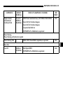
MAINTAINING YOUR VEHICLE . . . . . . . . . . . . . . . . . . . . . . . . . . . . . . . . . . . . . . . . . . . . . . . . . . . . . . . . . 251
7
8
MAINTENANCE SCHEDULES . . . . . . . . . . . . . . . . . . . . . . . . . . . . . . . . . . . . . . . . . . . . . . . . . . . . . . . . . . . . 303
8
9
IF YOU NEED CONSUMER ASSISTANCE . . . . . . . . . . . . . . . . . . . . . . . . . . . . . . . . . . . . . . . . . . . . . . . . . 311
9
10
INDEX . . . . . . . . . . . . . . . . . . . . . . . . . . . . . . . . . . . . . . . . . . . . . . . . . . . . . . . . . . . . . . . . . . . . . . . . . . . . . . . . . . 317
10
INTRODUCTION
CONTENTS
Introduction. . . . . . . . . . . . . . . . . . . . . . . . . . . . . . . . . 4
How to Use this Manual . . . . . . . . . . . . . . . . . . . . . . 5
Warnings and Cautions . . . . . . . . . . . . . . . . . . . . . . 5
Vehicle Identification Number, Sample
and Location . . . . . . . . . . . . . . . . . . . . . . . . . . . . . . . . 5
Vehicle Safety Certification Label, Sample
and Location . . . . . . . . . . . . . . . . . . . . . . . . . . . . . . . . 6
Vehicle/Engine Emission Label, Sample
and Location . . . . . . . . . . . . . . . . . . . . . . . . . . . . . . . . 8
Environmental Concerns and
Recommendations . . . . . . . . . . . . . . . . . . . . . . . . . . . 9
Drinking Alcohol or taking Drugs
while driving . . . . . . . . . . . . . . . . . . . . . . . . . . . . . . . 9
Information Regarding Electronic
Recording Devices . . . . . . . . . . . . . . . . . . . . . . . . . . 10
Stickers . . . . . . . . . . . . . . . . . . . . . . . . . . . . . . . . . . . . 10
1
4 INTRODUCTION
INTRODUCTION
This manual provides information needed to operate
and understand the vehicle and its components.
Additional detailed information is contained in the
Owner’s Warranty Information Book and the Sprinter
Service Booklet.
WARNING!
Be sure to read the Operating Instructions. Otherwise you may not be aware of certain risks and
could injur yourself or others.
Sprinter vehicles are equipped with a variety of
components. Not all of the information contained in
this manual applies to every vehicle.
IMPORTANT: Descriptions and specifications in this
manual were in effect at the time of printing.
For your reference, keep this manual in the vehicle at
all times.
DaimlerChrysler Vans LLC reserves the right to
discontinue models and to change specifications or
design at any time without notice and without
incurring
any
obligation.
Descriptions
and
specifications contained in this publication provide no
warranty, expressed or implied, and are subject to
revisions and publication of new editions without
notice.
WARNING!
Engine exhaust, some of its constituents, and certain vehicle components contain or emit chemicals known to the State of California to cause
cancer and birth defects or other reproduction
harm. In addition, certain fluids contained in vehicles, and certain products of component wear,
contain chemicals known to the State of California to cause cancer and birth defects or other reproductive harm.
INTRODUCTION 5
HOW TO USE THIS MANUAL
Consult the table of contents to determine which
section contains the information you desire.
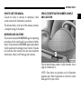
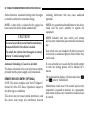
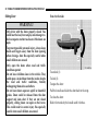
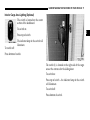
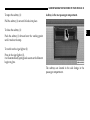
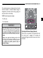
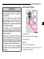
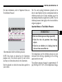
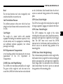
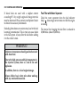
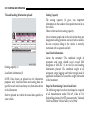
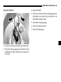
VEHICLE IDENTIFICATION NUMBER, SAMPLE
AND LOCATION
The detailed index, at the rear of this manual, contains
a complete listing of all subjects.
WARNINGS AND CAUTIONS
This manual contains WARNINGS against operating
procedures which could result in an accident or bodily
injury. It also contains CAUTIONS against procedures
which could result in damage to your vehicle. If you do
not read this entire manual you may miss important
information. Observe all Warnings and Cautions.
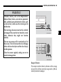
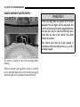
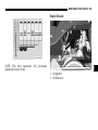
Vehicle identification number, visible (location: lower
edge of windshield) (1)
NOTE: Data shown on placards are for illustration
purposes only. Refer to placards on vehicle for actual
data specific to your vehicle.
1
6 INTRODUCTION
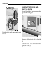
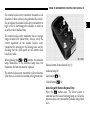
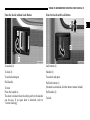
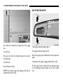
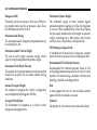
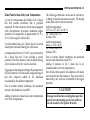
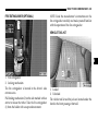
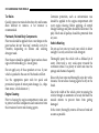
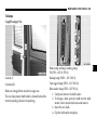
VEHICLE SAFETY CERTIFICATION LABEL,
SAMPLE AND LOCATION
Location: below the driver’s seat on an outward facing
position of the mounting pillar.
Vehicle identification number (location: on the chassis,
right hand).
Incomplete vehicle certification label for chassis/cab.
(1)
Certification Label (vehicle identification number,
permissible weights) (2)
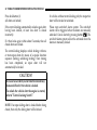
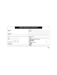
INTRODUCTION 7
Sample Incomplete Vehicle Certification Label
(Label 1)
NOTE: Data shown on label are for illustration
purposes only. Data are specific to each vehicle and
may vary from data shown in the illustrations.
Refer to label on vehicle for actual data specific to your
vehicle.
Sample Certification Label (Label 2)
1
8 INTRODUCTION
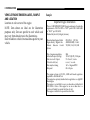
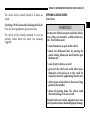
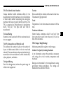
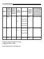
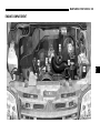
VEHICLE/ENGINE EMISSION LABEL, SAMPLE
AND LOCATION
Location: on valve cover of the engine
NOTE: Data shown on label are for illustration
purposes only. Data are specific to each vehicle and
may vary from data shown in the illustrations.
Refer to label on vehicle for actual data specific to your
vehicle.
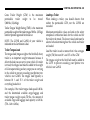
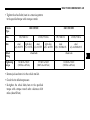
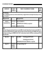
Sample:
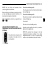
Important Engine Information
This is a LOW EMISSION VEHICLE engine and meets all applicable
requirements of US EPA CFFV as “ILEV” per 40 CFR 88 and CARB
as “ULEV” per CCR 1956.8
DaimlerChrysler AG, Stuttgart, Germany
Mercedes-Benz Engine, Model
Engine Family / Engine Code
Exhaust
Emission
Control
System
OM 647 LA CID 164
4 MBXH2.69DJB / Code I
TC, EMC, CAC, OC, EGR
Date of engine manufacture
Advertised output (SAE gr.)
Fuel rate at adv. Output
Valve lash cold (ins.)
Basic injection timing
Idle speed
2004
115 kW (154 HP) /3800 rpm
55 - 63 mm3 / stroke
n.a. int. / n.a. exh..
14.5 ± 1 degrees BTDC
680 ± 50 rpm
This engine conforms to US, EPA, CARB and Canada regulations
applicable to 2004 Model Year.
This engine has a primary intended service application as a light HD
diesel engine.
This engine is not certified for use in an urban bus as defined at 40
CFR 86.093.-2. Sales of this engine for use in an urban bus is a
violation of Federal Law under the Clean Air Act.
This engine is certified to be operated on diesel fuel.
INTRODUCTION 9
ENVIRONMENTAL CONCERNS AND
RECOMMENDATIONS
In this manual, whenever you see instructions to
discard materials, you should first attempt to reclaim
and recycle them. To preserve our environment, follow
appropriate environmental rules and regulations
when disposing of materials.
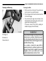
DRINKING ALCOHOL OR TAKING DRUGS WHILE
DRIVING
WARNING!
Drinking or taking drugs and driving can be a
very dangerous combination. Even a small
amount of alcohol or drugs can affect your reflexes, perceptions and judgement.
The possibility of a serious or even fatal accident
is sharply increased when you drink or take drugs
and drive.
Never drink or take drugs and drive or allow
anyone to drive after drinking or taking drugs.
1
10 INTRODUCTION
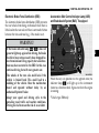
INFORMATION REGARDING ELECTRONIC
RECORDING DEVICES
(Including notice pursuant to California Code § 9951)
Please note that your vehicle is equipped with devices
that can record vehicle systems data.
This information helps, for example, to diagnose
vehicle systems after a collision and to continuously
improve vehicle safety. DaimlerChrysler may access
the information and share it with others
• for safety research or vehicle diagnosis purposes
• with the consent of the vehicle owner or lessee
• in response to an official request by law
enforcement or other government agency
• for use in dispute resolution involving
DaimlerChrysler, its affiliates or sales/service
organization and/or
• as otherwise required or permitted by law.
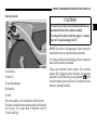
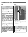
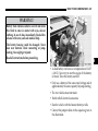
STICKERS
There are various warning stickers affixed to the motor
home. Their purpose is to make you and others aware
of various dangers.
WARNING!
Do not remove any warning stickers.
If you remove the warning stickers, you or others
may not be aware of certain dangers and could be
injured.
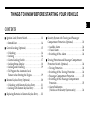
THINGS TO KNOW BEFORE STARTING YOUR VEHICLE
2
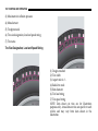
CONTENTS
Ignition Lock/Starter Switch . . . . . . . . . . . . . . . . . 13
Immobilizer . . . . . . . . . . . . . . . . . . . . . . . . . . . . . . 14
Central Locking (Optional) . . . . . . . . . . . . . . . . . .
Unlocking: . . . . . . . . . . . . . . . . . . . . . . . . . . . . . . .
Locking: . . . . . . . . . . . . . . . . . . . . . . . . . . . . . . . . .
Central Locking Switch . . . . . . . . . . . . . . . . . . . .
Locking Status Display . . . . . . . . . . . . . . . . . . . .
Locking and Unlocking . . . . . . . . . . . . . . . . . . . .
To Program the Automatic Lock
Feature when Starting the Engine . . . . . . . . . . .
15
16
16
17
18
19
19
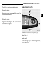
Remote Keyless Entry (Optional) . . . . . . . . . . . . . 20
Unlocking with Remote Keyless Entry . . . . . . . 21
Locking with Remote Keyless Entry . . . . . . . . . 22
Replacing Batteries in Remote Keyless Entry . . . 22
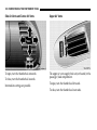
Security System with Towing and Passenger
Compartment Protection (Optional) . . . . . . . . . . .
Audible Alarm . . . . . . . . . . . . . . . . . . . . . . . . . . .
Visual Alarm . . . . . . . . . . . . . . . . . . . . . . . . . . . . .
Switching off the Alarm . . . . . . . . . . . . . . . . . . .
Towing Protection and Passenger Compartment
Protection Switch (Optional) . . . . . . . . . . . . . . . . . .
Towing Protection . . . . . . . . . . . . . . . . . . . . . . . .
Switching off the Towing Protection . . . . . . . . .
Passenger Compartment Protection . . . . . . . . .
Switching off the Passenger Compartment
Protection . . . . . . . . . . . . . . . . . . . . . . . . . . . . . . . .
Alarm Pushbutton
(Vehicles with Security Systems only) . . . . . . .
23
24
24
24
24
24
24
25
25
26
12 THINGS TO KNOW BEFORE STARTING YOUR VEHICLE
Opening/Closing doors . . . . . . . . . . . . . . . . . . . . . 27
Sliding Door . . . . . . . . . . . . . . . . . . . . . . . . . . . . . 30
Rear Cargo Doors . . . . . . . . . . . . . . . . . . . . . . . . . 33
Passenger/Cargo Area Door 37
Airbag and Belt Tensioners . . . . . . . . . . . . . . . . . .
SRS Malfunction Indicator Lamp . . . . . . . . . . . .
Belt Tensioners . . . . . . . . . . . . . . . . . . . . . . . . . . .
Safety Precautions for the Airbag . . . . . . . . . . .
Occupant Restraints . . . . . . . . . . . . . . . . . . . . . . . . . 39
Pedals . . . . . . . . . . . . . . . . . . . . . . . . . . . . . . . . . . . . . 52
Seat Belts . . . . . . . . . . . . . . . . . . . . . . . . . . . . . . . . . .
Seat Belt Warning Lamp and
Airbag Malfunction . . . . . . . . . . . . . . . . . . . . . . .
Fastening and Removing . . . . . . . . . . . . . . . . . .
Belt Height Adjustment . . . . . . . . . . . . . . . . . . . .
Engine Break-In Specifications . . . . . . . . . . . . . . . . 52
The first 1,000 miles (about 1,500 km) . . . . . . . . 52
Engine Oil Consumption . . . . . . . . . . . . . . . . . . . 53
41
44
45
46
Driver’s Airbag . . . . . . . . . . . . . . . . . . . . . . . . . . . . . 47
Front Seat Passenger Airbag (not in conjunction
with folding seat in partition wall) . . . . . . . . . . . . 48
49
49
49
50
Safety Tips . . . . . . . . . . . . . . . . . . . . . . . . . . . . . . . . . 53
Inhalation of Exhaust Gas . . . . . . . . . . . . . . . . . . . . 54
Tie Down Rings (Optional) . . . . . . . . . . . . . . . . . . . 54
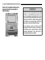
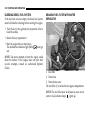
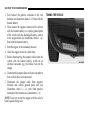
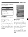
THINGS TO KNOW BEFORE STARTING YOUR VEHICLE 13
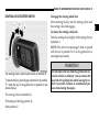
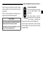
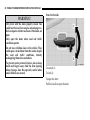
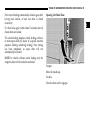
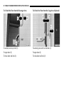
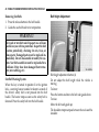
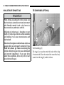
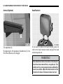
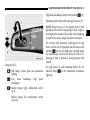
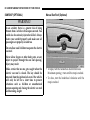
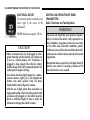
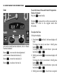
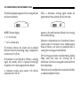
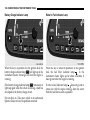
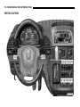
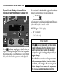
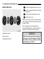
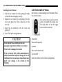
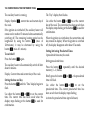
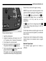
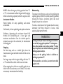
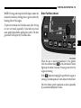
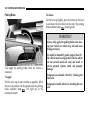
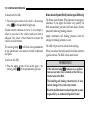
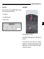
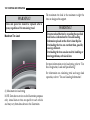
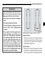
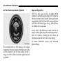
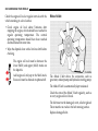
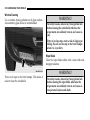
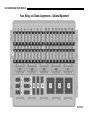
IGNITION LOCK/STARTER SWITCH
To engage the steering wheel lock:
After removing the key, turn the steering wheel until
the steering wheel lock engages.
To release the steering wheel lock:
Turn the steering wheel slightly while turning the key
to position 1.
NOTE: If the driver’s or passenger’s door is opened
with the key in position 0 or 1 in the ignition lock, a
warning buzzer sounds.
WARNING!
The steering wheel is locked when the key is removed (0)
To remove the key, place the gear selector lever in position
"P"; rotate the key in the ignition lock to position 0; and
remove the key.
The steering wheel is unlocked (1)
Preheating and driving position (2)
Start position (3)
Do not remove the key from the ignition lock unless the vehicle is stationary. Always remove the
key from the ignition lock when leaving the vehicle to prevent children or unauthorized persons from starting the engine.
2
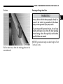
14 THINGS TO KNOW BEFORE STARTING YOUR VEHICLE
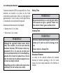
Immobilizer
The immobilizer is automatically activated when the
key is removed from the ignition lock. The engine
cannot be started. As soon as the correct key is inserted
into the ignition lock, the immobilizer is deactivated.
For notes on the remote keyless entry, refer to "Remote
Keyless Entry".
NOTE: If the engine cannot be started and the displays
Á and î appear alternately in the multi-function
indicator when the key is in position 2 in the ignition
lock, a fault has developed or the key used has not been
activated.
Remove the key and repeat the starting procedure. If
the engine still cannot be started, consult an authorized
Sprinter Dealer.
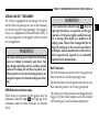
THINGS TO KNOW BEFORE STARTING YOUR VEHICLE 15
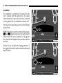
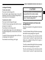
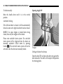
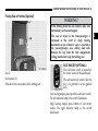
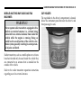
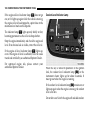
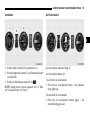
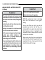
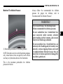
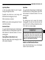
CENTRAL LOCKING (OPTIONAL)
WARNING!
For personal security and safety in the event of an
accident, lock the vehicle doors when you drive
as well as when you park and leave the vehicle.
To unlock (1)
To lock (2)
CAUTION!
An unlocked vehicle is an invitation to thieves.
Always remove the key from the ignition and lock
all doors when leaving the vehicle unattended.
To unlock (1)
To lock (2)
2
16 THINGS TO KNOW BEFORE STARTING YOUR VEHICLE
When leaving the vehicle always remove the key
from the ignition lock, and lock your vehicle.
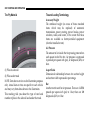
Unlocking:
If a door lock or interior handle on the driver or front
seat passenger door is unlocked, only the driver or
front seat passenger door will be unlocked.
Do not leave children unsupervised in the vehicle,
even if they are secured by a child restraint system.
The children could
NOTE: If a door lock or interior handle on the sliding
door or tailgate is unlocked, only the sliding door or
tailgate will be unlocked.
• injure themselves on parts of the vehicle
Locking:
All doors are automatically locked if a door lock or
interior handle is locked.
WARNING!
• release the child-proof locks by pressing the
central locking button and could thereby open
the doors and
• cause injury to others as a result
• get out of the vehicle and could either injure
themselves when doing so or they could be
injured by the traffic approaching from the rear
• suffer serious or fatal effects in the event of long
periods of hot weather
• release the parking brake. The vehicle could
then start moving of its own accord.
Unsupervised use of vehicle equipment may cause
severe personal injuries, death and property damage.
NOTE: If the central locking automatically unlocks
again after having been locked, at least one door is
closed incorrectly.
If it then locks again within about 5 seconds, then all
closed doors are locked.
The central locking displays vehicle locking with one
or more open doors by means of a special function
sequence (locking, unlocking, locking). Once closing
has been completed, an open door will not
automatically be locked.
THINGS TO KNOW BEFORE STARTING YOUR VEHICLE 17
After the engine is started (about 1 second), all doors
with the exception of the driver-side door are locked
automatically.
NOTE: In vehicles without central locking only the
respective door will be locked or unlocked.
CAUTION!
In case of an accident, rescue from the outside may
be more difficult if the vehicle is locked.
To unlock the vehicle after the engine is started,
refer to "Central Locking Switch".
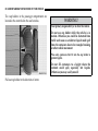
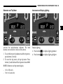
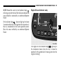
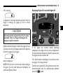
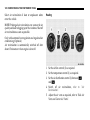
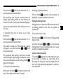
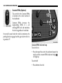
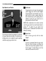
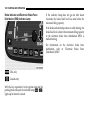
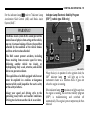
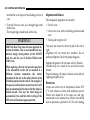
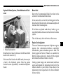
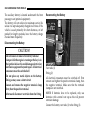
Central Locking Switch
The central locking switch is located
on the center section of the
dashboard.
The entire vehicle or just the
passenger door and the cargo doors
can be locked or unlocked from
inside the vehicle with the central locking switch.
After the engine is started (about 1 second), all doors
with the exception of the driver-side door are locked
(standard setting).
2
18 THINGS TO KNOW BEFORE STARTING YOUR VEHICLE
WARNING!
When leaving the vehicle always remove the key
from the ignition lock, and lock your vehicle.
Do not leave children unsupervised in the vehicle,
even if they are secured by a child restraint system.
The children could
• injure themselves on parts of the vehicle
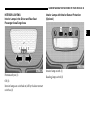
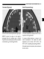
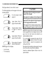
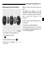
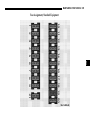
Locking Status Display
Left-hand indicator lamp is illuminated:
The driver’s door is locked.
Right-hand indicator lamp is illuminated:
Front-seat passenger door and rear-seat passenger
area/cargo area are locked.
Both indicator lamps are illuminated:
The entire vehicle is locked.
• release the child-proof locks by pressing the
central locking button and could thereby open
the doors and
If an indicator lamp flashes:
At least one door has not been properly closed.
• cause injury to others as a result
once the remote keyless entry transmitter has been
used to completely lock the vehicle;
• get out of the vehicle and could either injure
themselves when doing so or they could be
injured by the traffic approaching from the rear
• suffer serious or fatal effects in the event of long
periods of hot weather
• release the parking brake. The vehicle could
then start moving of its own accord.
Unsupervised use of vehicle equipment may cause
severe personal injuries, death and property damage.
NOTE: The indicator lamps go out,
if the ignition lock is in the position 0, and once the
interior handles/closing cylinders have been used to
completely lock the vehicle;
after about 15 minutes in position 0 in the ignition lock.
The display can be reactivated by pressing the central
locking switch, located on the center section of the
dashboard.
THINGS TO KNOW BEFORE STARTING YOUR VEHICLE 19
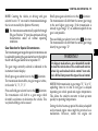
Locking and Unlocking
To lock entire vehicle:
Press top of central locking switch.
The left and the right indicator lamp in the switch
illuminate. If one of the two indicator lamps blinks, at
least one door is not closed properly.
To unlock entire vehicle:
Press top of central locking switch again.
To lock the front-seat passenger door and the rear-seat
passenger area/cargo area:
Press bottom of central locking switch.
The right indicator lamp in the switch illuminates. If
the indicator lamp blinks, at least one door is not closed
properly.
To unlock the front-seat passenger door and the rearseat passenger area/cargo area:
Press bottom of central locking switch again.
CAUTION!
In case of an accident, rescue from the outside may
be more difficult if the vehicle is locked.
To unlock the vehicle after the engine is started,
refer to ‘‘Central Locking Switch’’.
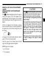
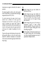
To Program the Automatic Lock Feature when
Starting the Engine
Place the key in position 2 in the ignition lock and close
all doors.
To switch off automatic locking of the front-seat passenger
door and the rear-seat passenger area/cargo area:
Press the central locking switch at the bottom and hold
it there for about 5 seconds. The right indicator lamp
flashes twice. Automatic locking when the engine is
started is switched off.
To switch on automatic locking of the front-seat passenger
door and the rear-seat passenger area/cargo area:
Press the central locking switch at the bottom and hold
it there for about 5 seconds. The right indicator lamp
2
20 THINGS TO KNOW BEFORE STARTING YOUR VEHICLE
flashes four times. Automatic locking when the engine
is started is switched on (standard setting).
including interference that may cause undesired
operation.
NOTE: A door which is closed after the engine has
been started will not be locked automatically.
NOTE: Any unauthorized modification to this device
could void the user’s authority to operate the
equipment.
CAUTION!
NOTE: Included with your vehicle are 2 remote
keyless entry transmitters plus removable mechanical
key.
In case of an accident, rescue from the outside may
be more difficult if the vehicle is locked.
To unlock the vehicle after the engine is started,
refer to ‘‘Central Locking Switch’’.
Keys which were not included with delivery must be
activated at an authorized Sprinter Dealer before they
can be used.
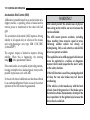
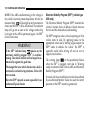
Automatic Unlocking in Case of an Accident
The doors will unlock in the event of certain accidents,
provided that the power supply is still maintained.
If a non-activated key is used, after the fourth attempt
to start, the starting process will be blocked for 1
minute.
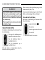
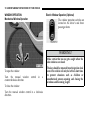
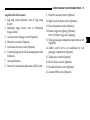
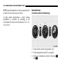
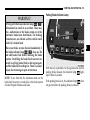
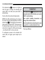
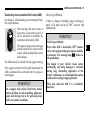
REMOTE KEYLESS ENTRY (OPTIONAL)
NOTE: This device complies with Part 15 Subpart C
Section 231 of the FCC Rules. Operation is subject to
the following two conditions:
This device may not cause harmful interference, and
this device must accept any interference received
The multi-function display will alternately show Á
and î, refer to "Immobilizer".
Malfunctions could occur if the remote keyless entry
transmitter is exposed to moisture. As a precaution,
both remote keyless entry transmitters should always
be carried.
THINGS TO KNOW BEFORE STARTING YOUR VEHICLE 21
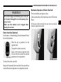
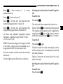
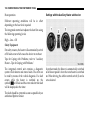
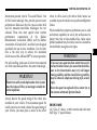
The remote keyless entry transmitter transmits in all
directions. It does not have to be pointed at the vehicle.
Do not expose the remote keyless entry transmitter to
high levels of electromagnetic radiation in order to
avoid the risk of malfunctions.
2
The remote keyless entry transmitter has an average
range of about 32 ft (about 10 m). Always verify the
correct operation of the remote keyless entry
transmitter by listening for the locking noise and by
checking that the white patch on the interior door
handle is visible.
When pressing the Œ or ‹ buttons, the indicator
lamp illuminates. If the indicator lamp does not
illuminate, the batteries must be replaced.
The remote keyless entry transmitter will not function
when there is a vehicle key inserted in the ignition lock.
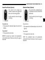
Release button for mechanical key (1)
Indicator lamp (2)
Lock button ‹ (3)
Unlock button Π(4)
Unlocking with Remote Keyless Entry
Press the Œ button once. The driver’s door is
unlocked and the hazard warning lamp, as well as the
remote keyless entry transmitter indicator lamp, blink
once.
22 THINGS TO KNOW BEFORE STARTING YOUR VEHICLE
Press the Πbutton a second time. The passenger
door and cargo doors are unlocked and the turn signal
lamps, as well as the remote keyless entry transmitter
indicator lamp, blink once again. The button must be
pressed a second time within about 2.5 seconds,
otherwise the second request to open can not be
performed.
NOTE: The vehicle is automatically locked again, if
within about 40 seconds of unlocking with the remote
keyless entry transmitter, none of the doors are
opened. The hazard warning lamp does not blink.
Locking with Remote Keyless Entry
Press the ‹ button. The entire vehicle is locked and
the hazard warning lamp blinks three times. The
remote keyless entry transmitter indicator lamp blinks
once.
If the hazard warning lamp does not blink, at least one
door is improperly closed. Check to see if there is a
door that is not properly closed or if there is a key in the
ignition lock. Remove key from ignition lock and/or
close doors properly and press the ‹ button again.
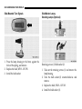
REPLACING BATTERIES IN REMOTE KEYLESS
ENTRY
Do not touch the battery contact surfaces (insert the
batteries with a lint-free cloth).
WARNING!
Keep batteries away from children.
Consult a doctor immediately if a battery is
swallowed.
Dispose of used batteries in an environmentally
responsible manner.
Danger of explosion if the battery is not correctly
replaced. Replacements should always be either
of the same type or one which has been
recommended by the manufacturer.
NOTE: Do not operate the remote control while the
battery is being replaced.
THINGS TO KNOW BEFORE STARTING YOUR VEHICLE 23
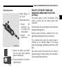
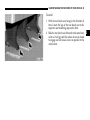
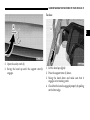
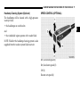
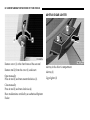
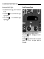
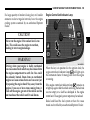
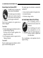
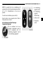
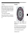
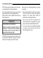
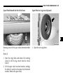
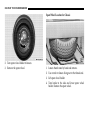
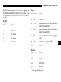
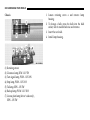
Replacing Batteries
Rated voltage: 6 V
DC (2x 3V)
Rated current:10 mA
1. Release
the
mechanical key
by pressing the
release button.
2. Remove
the
battery cover.
3. Remove the battery and install
new one (note correct polarity;
positive terminal up).
4. Press on the battery cover until it
snaps into place.
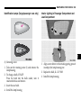
SECURITY SYSTEM WITH TOWING AND
PASSENGER COMPARTMENT PROTECTION
(OPTIONAL)
The security system is ready for operation, if the
vehicle is locked with the remote keyless entry
transmitter.
If a door is open, the security system is not switched on
during the locking process.
Security system activation is indicated by the turn
signal lamps flashing three times in succession.
For a function check, when the security system is
switched on, the indicator lamps in the towing
protection/passenger compartment protection switch
flash.
The security system will switch off if the vehicle is
unlocked using the remote keyless entry transmitter.
The turn signal lamps flash once.
2
24 THINGS TO KNOW BEFORE STARTING YOUR VEHICLE
The alarm is triggered if the security system has been
activated and
• A door is opened,
• a door is unlocked from inside,
• the engine cover is opened,
• the key is used to unlock the vehicle at any door,
• the key is turned to position 2 in the ignition lock.
Audible Alarm
The horn sounds for about 25 seconds.
Visual Alarm
The turn signal lamps flash for about 4 minutes.
Switching off the Alarm
The alarm will switch off immediately if the vehicle is
unlocked using the remote keyless entry transmitter.
NOTE: Do not manually unlock the doors as this will
trigger the alarm.
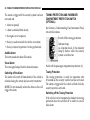
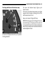
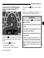
TOWING PROTECTION AND PASSENGER
COMPARTMENT PROTECTION SWITCH
(OPTIONAL)
See Section 4, Understanding Your Instrument Panel,
for switch locations.
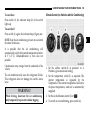
Switch off the towing protection
Indicator lamp
As a function check, (1) the indicator
lamp (2) flashes when the security
system is switched on.
Switch off the passenger compartment protection (3).
Towing Protection
The towing protection is ready for operation after
30 seconds as the security system has been activated.
The alarm is triggered if the vehicle is lifted while the
security system is activated.
Switching off the Towing Protection
If the vehicle is to be transported or loaded, the towing
protection must be switched off in order to avoid a
false alarm.
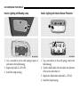
THINGS TO KNOW BEFORE STARTING YOUR VEHICLE 25
1. Place the key in position 0 or 1 in the ignition lock.
2. Press the switch up (1) to switch off the towing
protection.
The indicator lamp (2) is briefly illuminated.
If passenger compartment protection will be switched
off as well, wait until the indicator lamp (2) goes out,
and
3. Press switch (3) downward.
The indicator lamp (2) flashes about 10 times.
To activate the setting (towing protection/passenger
compartment protection switched off):
4. Keep the key in locking position in the driver’s
door lock for more than 2 seconds or
5. lock the vehicle using the remote keyless entry
transmitter.
The towing protection will remain switched off until
the vehicle is locked again with the remote keyless
entry transmitter.
NOTE: The alarm will switch off immediately if the
vehicle is centrally unlocked using the remote keyless
entry transmitter.
Passenger Compartment Protection
The passenger compartment protection is ready for
operation 30 seconds after the security system has been
activated. The alarm is triggered if movement inside
the vehicle is registered while the security system is
activated.
NOTE: Close the side windows and the glass tilting
roof.
Do not leave any objects (mascots, hangers) on the
interior mirror or on the roof grab handles, as these
could trigger a false alarm.
Switching off the Passenger Compartment
Protection
If persons or animals remain in the locked vehicle,
switch off the passenger compartment protection to
prevent a false alarm.
1. Place the key in position 0 or 1 in the ignition lock.
2. Press the switch downward (3) to switch off the
passenger compartment protection. The indicator
lamp (2) flashes about 10 times.
If towing protection is to be switched off as well, wait
until the indicator lamp (2) goes out, and
2
26 THINGS TO KNOW BEFORE STARTING YOUR VEHICLE
To activate the setting (passenger compartment/
towing protection switched off):
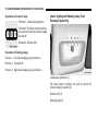
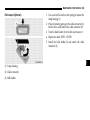
Alarm Pushbutton (Vehicles with Security Systems
only)
See Section 4, Understanding Your Instrument Panel,
for switch locations.
4. Lock the vehicle using the remote keyless entry
transmitter.
Trigger the alarm manually/lock the
vehicle.
The passenger compartment protection will remain
switched off until the vehicle is locked again with the
remote keyless entry transmitter.
The audible and visual alarm can be
triggered manually by using the
alarm pushbutton.
3. Press switch up (1).
The indicator lamp (2) is briefly illuminated.
NOTE: The alarm will switch off immediately if the
vehicle is centrally unlocked using the remote keyless
entry transmitter.
Audible Alarm
The horn sounds until the alarm is switched off.
Visual Alarm
The turn signal lamps flash until the alarm is switched
off.
Trigger the alarm manually and lock the vehicle.
Press the alarm pushbutton upward once.
The indicator lamp flashes in the towing/passenger
compartment protection switch.
THINGS TO KNOW BEFORE STARTING YOUR VEHICLE 27
The vehicle will be centrally locked if all doors are
closed.
Switching Off the Alarm and Unlocking the Vehicle
Press the alarm pushbutton up one more time.
The vehicle will be centrally unlocked if it was not
centrally locked before the alarm was manually
triggered.
OPENING/CLOSING DOORS
Front Doors
WARNING!
Do not leave children unsupervised in the vehicle,
even if they are secured by a child restraint system. The children could
• injure themselves on parts of the vehicle
• release the child-proof locks by pressing the
central locking button and could thereby open
the doors and
• cause injury to others as a result
• get out of the vehicle and could either injure
themselves when doing so or they could be
injured by the traffic approaching from the rear
• suffer serious or fatal effects in the event of long
periods of hot weather
• release the parking brake. The vehicle could
then start moving of its own accord.
Unsupervised use of vehicle equipment may cause
severe personal injuries, death and property damage.
2
28 THINGS TO KNOW BEFORE STARTING YOUR VEHICLE
WARNING!
Only drive with the doors properly closed. You
could lose the load, for example, and endanger vehicle occupants or other road users if the doors are
open.
Only open the doors when road and traffic
conditions permit.
Do not leave children alone in the vehicle. They
could open a locked door from the inside despite
the road and traffic conditions, thereby
endangering themselves and others.
To prevent severe personal injuries, always keep
hands and fingers away from the door opening
when closing a door. Be especially careful when
small children are around.
From the Outside
To unlock (1)
To lock (2)
To open the door:
Pull the handle to open the door.
THINGS TO KNOW BEFORE STARTING YOUR VEHICLE 29
From the Inside
CAUTION!
In case of an accident, rescue from the outside may
be more difficult if the vehicle is locked.
To unlock the vehicle after the engine is started,
refer to "Central Locking Switch".
NOTE: The driver’s and passenger’s doors cannot be
locked when they are open (lockout protection).
In vehicles without central locking only the respective
door will be locked or unlocked.
To unlock (1)
To lock (2)
To unlock and open
Pull handle.
To lock:
Press the handle in. All closed doors will be locked.
The door is locked when the white patch in the handle
can be seen. If an open door is detected, refer to
"Central Locking".
Please note anti-theft alarm system: The anti-theft
alarm will be triggered when the doors are manually
unlocked. Cancel alarm by pressing button Œ. The
anti-theft alarm system will not be activated when the
doors are manually locked.
2
30 THINGS TO KNOW BEFORE STARTING YOUR VEHICLE
Sliding Door
From the Outside
WARNING!
Only drive with the doors properly closed. You
could lose the load, for example, and endanger vehicle occupants or other road users if the doors are
open.
To prevent possible personal injury, always keep
hands and fingers away from the door opening
when closing a door. Be especially careful when
small children are around.
Only open the doors when road and traffic
conditions permit.
Do not leave children alone in the vehicle. They
could open a locked door from the inside despite
the road and traffic conditions, thereby
endangering themselves and others.
Do not leave doors open on uphill or downhill
grades. Doors could be released from the door
support and slam shut. If they are not closed
properly, sliding doors can open on their own.
This could result in severe injury. Be especially
careful when small children are around.
To unlock (1)
To lock (2)
To open the door:
Pull the handle and slide the door back to the stop.
To close the door:
Slide it forwards by the handle until it latches.
THINGS TO KNOW BEFORE STARTING YOUR VEHICLE 31
From the Inside without Lock Button
From the Inside with Lock Button
2
To unlock (1)
Lock button (1)
To lock (2)
Handle (2)
To unlock and open:
To unlock and open:
Pull handle.
Pull lock button (1)
(the door is unlocked, all other doors remain locked).
To lock:
Press the handle in.
The door is locked when the white patch in the handle
can be seen. If an open door is detected, refer to
"Central Locking".
Pull handle (2).
To lock:
32 THINGS TO KNOW BEFORE STARTING YOUR VEHICLE
Press lock button (1)
(all doors are locked)
In vehicles without central locking only the respective
door will be locked or unlocked.
If the central locking automatically unlocks again after
having been locked, at least one door is closed
incorrectly.
Please note anti-theft alarm system: The anti-theft
alarm will be triggered when the doors are manually
unlocked. Cancel alarm by pressing button Œ. The
anti-theft alarm system will not be activated when the
doors are manually locked.
If it then locks again within about 5 seconds, then all
closed doors are locked.
The central locking displays vehicle locking with one
or more open doors by means of a special function
sequence (locking, unlocking, locking). Once closing
has been completed, an open door will not
automatically be locked.
CAUTION!
In case of an accident, rescue from the outside may
be more difficult if the vehicle is locked.
To unlock the vehicle after the engine is started,
refer to "Central Locking Switch".
NOTE: If an open sliding door is locked before being
closed, then only the sliding door will be locked.
THINGS TO KNOW BEFORE STARTING YOUR VEHICLE 33
Rear Cargo Doors
From the Outside
WARNING!
2
Only drive with the doors properly closed. You
could lose the load, for example, and endanger vehicle occupants or other road users if the doors are
open.
To prevent possible personal injury, always keep
hands and fingers away from the door opening
when closing a door. Be especially careful when
small children are around.
Only open the doors when road and traffic
conditions permit.
Do not leave children alone in the vehicle. They
could open a locked door from the inside despite
the road and traffic conditions, thereby
endangering themselves and others.
When the rear cargo doors are opened to an angle
of 90° (catch position), more than 50% of the rear
lamps are concealed. When the door is open in this
manner, you should warn others in accordance
with legal requirements.
To unlock (1)
To lock (2)
To open the door:
Pull the handle to open the door.
34 THINGS TO KNOW BEFORE STARTING YOUR VEHICLE
From the Inside without Lock Button
From the Inside with Lock Button
To unlock and open:
Pull handle.
Lock button (1)
To lock:
Press the handle in.
The door is locked when the white patch in the handle
can be seen. If an open door is detected, refer to
"Central Locking".
To unlock and open:
Pull lock button (1)
(the door is unlocked, all other doors remain locked).
Handle (2)
Pull handle (2).
To lock:
Press lock button (1)
(all doors are locked).
THINGS TO KNOW BEFORE STARTING YOUR VEHICLE 35
If the central locking automatically unlocks again after
having been locked, at least one door is closed
incorrectly.
Opening Left-Hand Door
2
If it then locks again within about 5 seconds, then all
closed doors are locked.
The central locking displays vehicle locking with one
or more open doors by means of a special function
sequence (locking, unlocking, locking). Once closing
has been completed, an open door will not
automatically be locked.
NOTE: In vehicles without central locking only the
respective door will be locked or unlocked.
To open:
Move the handle up.
To close:
Close the door until it engages.
36 THINGS TO KNOW BEFORE STARTING YOUR VEHICLE
To lock manually:
Opening Angle 270°
Move the handle down until it is in the vertical
position.
Automatic locking:
If the left-hand door is closed, it will be automatically
locked as soon as the right-hand door has been closed.
NOTE: If an open tailgate is locked before being
closed, then only the tailgate will be locked.
Please note anti-theft alarm system: The anti-theft
alarm system will be triggered when the doors are
manually unlocked. Cancel alarm by pressing
button Œ. The anti-theft alarm system will not be
activated when the doors are manually locked.
To open:
Unhinge the door check strap.
Open the door 270° and press the door stay against the
outer sidewalls. The doors will be kept in this position
by retaining plates.
THINGS TO KNOW BEFORE STARTING YOUR VEHICLE 37
To close:
Passenger/Cargo Area Door
WARNING!
Always drive with the doors properly closed, because if the vehicle is operated with the doors
open, serious personal injury may result.
To prevent possible personal injury, always keep
hands and fingers away from the door opening
when closing a door. Be especially careful when
small children are around.
NOTE: The maximum cargo area door height is 5 feet
7 inches (176 cm).
Pull the doors away from the retaining plates on the
outer sidewalls.
2
38 THINGS TO KNOW BEFORE STARTING YOUR VEHICLE
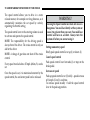
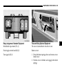
To Unlock the Door from the Passenger Area
To Unlock the Door from the Cargo Area (Optional)
To unlock, turn key to left (1)
To unlock, press latch in direction (1)
To open door (2)
To open door (2)
To close door and lock (3)
To close door and lock (3)
THINGS TO KNOW BEFORE STARTING YOUR VEHICLE 39
OCCUPANT RESTRAINTS
Seat belts, belt tensioners, airbag and child restraint
systems are independent restraint systems whose
functions complement each other.
All states and provinces require use of child restraints
that comply with U.S. Federal Motor Vehicle Safety
Standard 213 and Canadian Motor Vehicle Safety
Standard 213.
All child restraint systems are designed to be secured
in vehicle seats by lap belts or the lap belt portion of a
lap-shoulder belt.
For your safety and that of your passengers, you must
use the seat belts and child restraint systems and use
them properly. We strongly recommend their use.
WARNING!
In a collision, you and your passengers can suffer
injuries, including fatalities, if you are not properly buckled up. You can strike the interior of your
vehicle or other passengers, or you can be thrown
out of the vehicle. Always be sure you and others
in your vehicle are buckled up properly.
WARNING!
Do not modify the components or electrical wiring of the restraint systems. This includes the installation of additional trim material, badges etc.
over the steering wheel hub, or front door trim
panels, and installation of additional electrical/
electronic equipment on or near restraint system
components and wiring.
Any work on the restraint systems should only be
carried out by an authorized Sprinter Dealer.
Unprofessional work can lead to the restraint
systems triggering incorrectly or failing.
Damaged seat belts or belts that were highly
stressed in an accident must be replaced and their
anchoring points must also be checked. Use only
belts installed or supplied by an authorized
Sprinter Dealer.
Do not pass belts over sharp edges.
Do not make any modification that could change
the effectiveness of the belts.
2
40 THINGS TO KNOW BEFORE STARTING YOUR VEHICLE
WARNING!
WARNING!
Airbag and belt tensioners are designed to function on a one-time-only basis. An airbag or belt
tensioner that was activated must be replaced.
When discarding of the airbag unit or emergency
tensioning retractor, you must follow our safety
instructions. These instructions are available at
your Sprinter Dealer.
An airbag system component integrated in the
steering wheel gets hot after the airbag has
inflated. Do not touch.
No modifications of any kind may be made to any
components or wiring of the restraint system.
Keep area between airbag and occupants free of
objects (e.g. packages, purses, umbrellas, etc.).
In addition, through improper work there is the
risk of rendering the restraint system inoperative.
Work on the restraint system must therefore only
be performed by an authorized Sprinter Dealer.
Given the considerable deployment speed and the
textile structure of the airbag, there is the possibility
of injuries and even death resulting from being
positioned too close to the airbag when it deploys.
Do not seat children less than 5 feet tall or 12 years
and under in the front. The back seat is the safest
place for children. If the vehicle is not equipped with
a back seat, children less than 5 feet tall or 12 years
and under must never ride in this vehicle. Never place
an infant seat on the front passenger seat.
Children less than 5 feet tall or 12 years and under
require a special restraint system for protection in
the event of an accident as they may be too small
to wear seat belts properly.
THINGS TO KNOW BEFORE STARTING YOUR VEHICLE 41
WARNING!
Children should never ride sitting on the lap of
another occupant. In an accident they will be completely without protection and could even be injured by the person they are sitting on. For the
safety of all occupants read the child restraint system manufacturer’s instructions carefully when
fitting any child restraint system.
When the child restraint is not in use, remove it
from the vehicle or secure it with the seat belt to
prevent the child restraint from becoming a
projectile in the event of an accident.
Do not leave children unsupervised in the vehicle,
even if they are secured by a child restraint
system.
SEAT BELTS
WARNING!
Always wear the seat belts, even for very shorttrips.
Wearing a seat belt incorrectly is dangerous. Seat
belts are designed to go around the large bones of
your body. These are the strongest parts of your
body and can take the forces of a collision the best.
Wearing your belt in the wrong place could make
your injuries in a collision much worse. You
might suffer internal injuries, or you could even
slide out of part of the belt. Follow these
instructions to wear your seat belt safely and to
keep your passengers safe, too.
A belt that is buckled into the wrong buckle will
not protect you properly. The lap portion could
ride too high on your body, possibly causing
injuries. Always buckle your belt into the buckle
nearest you.
A belt that is too loose will not protect you as well.
In a sudden stop you could move too far forward,
increasing the possibility of injury.
2
42 THINGS TO KNOW BEFORE STARTING YOUR VEHICLE
WARNING!
Wear your seat belt snugly.
A belt that is worn under your arm is very
dangerous. Your body could strike the inside
surfaces of the vehicle in a collision, increasing
head and neck injury. A belt worn under the arm
can cause internal injuries. Ribs aren’t as strong as
shoulder bones. Wear the belt over your shoulder
so that your strongest bones will take the force in
collision.
A shoulder belt placed behind you will not protect
you from injury during a collision. You are more
likely to hit your head in a collision if you do not
wear your shoulder belt. The lap and shoulder
belt are meant to be used together.
Pregnant women should also use a lapshoulder
belt. The lap belt portion should be positioned as
low as possible on the hips to avoid any possible
pressure on the abdomen.
Two people should never be belted into a single
seat belt. People belted together can crash into one
another in an accident, hurting one another badly.
WARNING!
Do not secure any objects with a seat belt if it is
also being used for one of the vehicle’s occupants.
Do not allow the seat belt straps to become caught
or to be damaged by sharp objects. A frayed or
torn belt could rip apart in a collision and leave
you with no seat belt protection. Inspect the belt
system periodically, checking for cuts, frays, or
loose parts. Damaged parts must be replaced
immediately.
Do not disassemble or modify the system. Seat
belt assemblies must be replaced after a collision
if they have been damaged (bent retractor, torn
webbing, etc.). Have damaged seat belt
assemblies replaced by an authorized Sprinter
Dealer. Only use seat belt assemblies approved by
the manufacturer.
Keep the backrest upright or nearly upright.
THINGS TO KNOW BEFORE STARTING YOUR VEHICLE 43
WARNING!
WARNING!
Never ride in a moving vehicle with the backrest
reclined. Sitting in an excessively reclined position can be dangerous. You could slide under the
seat belt in a collision. If you slide under it, the
belt would apply force at the abdomen or neck.
This could result in severe personal injuries and
death.
In the same crash, the possibility for injury or
death is lessened with your seat belt buckled.
The backrest and seat belt provide the best
restraint when the wearer is in an upright position
and the belt is properly positioned on the body.
No modifications are to be made to the seat belts,
their anchorages, the inertia reels or belt buckles.
Failure to wear and properly fasten and position your
seat belt greatly increases your risk of injuries and
their likely severity in an accident. You and your
passengers should always wear seat belts.
If you are ever in an accident, your injuries can be
considerably more severe without your seat belt
properly buckled. Without your seat belt buckled,
you are much more likely to hit the interior of the
vehicle or to be ejected from it. You can be
seriously injured or killed.
Seat belts which have been subjected to heavy
loads in an accident must be replaced and their
anchorages must also be checked. Only use seat
belts which have been supplied and installed by
an authorized Sprinter Dealer.
2
44 THINGS TO KNOW BEFORE STARTING YOUR VEHICLE
Seat Belt Warning Lamp and Airbag Malfunction
When the key is in position 2 in the ignition lock, the
warning lamp < lights up for about 6 seconds; this
takes place whether or not the driver’s seat belt is
fastened.
If the driver’s safety belt remains unfastened after 153
seconds, the warning lamp < stops flashing and the
warning signal stops sounding. The warning lamp
< lights up for as long as the driver’s safety belt is
not fastened.
The warning lamp < must go out after about
6 seconds if the driver’s safety belt is fastened, or the
vehicle is standing still and the driver’s door is opened.
If the warning lamp < flashes after the first 6
seconds and no warning signal is audible, the
malfunction indicator lamp 1 is defective.
If after about 6 seconds, the driver’s safety belt is not
fastened with all doors closed,
Have the malfunction indicator lamp 1checked and
repaired by an authorized Sprinter Dealer as soon as
possible.
• and the vehicle speed does not exceed 15 mph (25
km/h), the warning lamp < remains on for as
long as the driver’s safety belt is not fastened.
• and the vehicle speed exceeds 15 mph (25 km/h),
the warning lamp < flashes and a warning signal
sounds, which is repeated increasingly frequently
until the driver’s safety belt is fastened, or for a
maximum of 153 seconds from the time the vehicle
speed exceeded 15 mph (25 km/h) if the driver’s
safety belt remains unfastened.
Malfunction indicator lamp 1, refer to “SRS
Malfunction Indicator Lamp”.
THINGS TO KNOW BEFORE STARTING YOUR VEHICLE 45
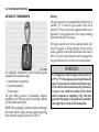
Fastening and Removing
Fastening Seat Belts
1. Pull the seat belt over the body. The seat belt must
not be twisted or you could be injured.
2. Press the tongue into the buckle and make sure that
it is heard to engage.
3. The seat belt must be tight across the body. Check
this immediately after fastening the seat belt, and at
regular intervals during the trip.
If necessary, tension the lap belt by pulling the
shoulder strap up in front of the body.
WARNING!
Belt tongue (1)
Belt buckle (2)
Release button (3)
A lap belt worn too high can increase the risk of
internal injury in a collision. The belt forces won’t
be at the strong hip and pelvic bones, but across
your abdomen. Always wear the lap part as low as
possible and keep it snug.
In an accident a twisted belt cannot fufill its
protective function. In a collision it could even cut
into you. Be sure the belt is straight. If you cannot
straighten a belt in your vehicle, take it to an
authorized Sprinter dealer and have it fixed.
2
46 THINGS TO KNOW BEFORE STARTING YOUR VEHICLE
Removing Seat Belts
1. Press the release button in the belt buckle.
2. Guide the seat belt back to its rest position.
Belt Height Adjustment
WARNING!
A frayed or torn belt could rip apart in a collision
and leave you with no protection. Inspect the belt
system periodically, checking for cuts, frays, or
loose parts. Damaged parts must be replaced immediately. Do not disassemble or modify the system. Seat belt assemblies must be replaced after a
collision if they have been damaged (bent retractor, torn webbing, etc.).
Seat Belt Warning System
When the key is turned to position 2 in the ignition
lock, a warning buzzer sounds for about 6 seconds if
the driver’s safety belt is not pressed into the belt
buckle. The buzzer stops as soon as the safety belt is
fastened. Press the safety belt into the belt buckle.
Belt height adjustment button (4)
Do not adjust the belt height while the vehicle is
moving.
To lower:
Press the button and move the belt sash guide down.
To raise:
Move the belt sash guide up.
The shoulder strap must pass between the neck and the
shoulder.
THINGS TO KNOW BEFORE STARTING YOUR VEHICLE 47
DRIVER’S AIRBAG
WARNING!
To reduce the risk of injury when the front airbag
inflates, it is very important for the driver to always be in a properly seated position and to wear
the seat belt. Since the airbag inflates with considerable speed and force, a proper seating position
with hands on the steering wheel will help to
keep you in a safe distance from the airbag. Keep
hands on the outside of the steering wheel rim.
Placing hands and arms inside the rim can increase the risk and the potential severity of hand/
arm injury when the driver front airbag inflates.
The driver’s airbag is located within the padded center
of the steering wheel.
2
48 THINGS TO KNOW BEFORE STARTING YOUR VEHICLE
FRONT SEAT PASSENGER AIRBAG (NOT IN
CONJUNCTION WITH FOLDING SEAT IN
PARTITION WALL)
WARNING!
To reduce the risk of injury when the front airbag
inflates, it is very important for the driver to always be in a properly seated position and to wear
the seat belt. Since the airbag inflates with considerable speed and force, a proper seating position
with hands on the steering wheel will help to
keep you in a safe distance from the airbag.
Do not place any pieces on the top of the
mounting lid above the airbag. If the airbag is
activated the pieces could be thrown into the
passenger compartment. This could result in
severe personal injuries and death.
THINGS TO KNOW BEFORE STARTING YOUR VEHICLE 49
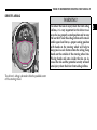
AIRBAG AND BELT TENSIONERS
The vehicle is equipped with an airbag for the driver
and the front seat passenger as well as belt tensioners
for the driver and the front passenger. The system is
known as a Supplemental Restraint System (SRS). It
has been designed to work together with the seat belt
and to supplement.
WARNING!
Do not put anything on or around the front airbag
covers or attempt to manually open them. You
may damage the airbags and you could be injured
because the airbags are not there to protect you.
These protective covers for the airbag cushions are
designed to open only when the airbags are inflating.
SRS Malfunction Indicator Lamp
When the key is in position 2 in the ignition lock, the
malfunction indicator lamp 1 will light up in the
instrument cluster for about 4 seconds as a function
check.
WARNING!
If the malfunction indicator lamp 1 does not
light up when the key is in position 2 in the ignition lock, if it flickers or lights up while the vehicle is moving, there might be a problem in the
airbag system. There is then a danger that the airbag will not deploy in the event of an accident or
will deploy when it should not do so. Have the vehicle inspected and repaired by an authorized
Sprinter Dealer without delay.
Belt Tensioners
The belt tensioners are located on the three-point seat
belts of the driver’s and front passenger seats.
The belt tensioners will not operate unless the key has
been turned to position 1 or 2 in the ignition lock.
The airbag and/or belt tensioners are designed to only
trigger in certain frontal impacts as not all accidents
call for airbag and/or belt tensioner deployment.
2
50 THINGS TO KNOW BEFORE STARTING YOUR VEHICLE
Safety Precautions for the Airbag
WARNING!
Airbags can seriously injure or kill you, especially
if you are close to the airbag when it deploys.
WARNING!
Do not lean forward when the vehicle is in motion.
Do not lean on the doors from inside the vehicle.
Always wear your seat belt. Airbags do not
replace seat belts but instead supplement the
protection offered by seat belts. Wearing a seat
belt also makes it less likely that you will be out
of position and will not be injured or killed as the
airbag deploys.
Do not put your feet on the dashboard.
Never place an infant seat which faces to the rear
on the front passenger seat. Children 12 years old
and under, and any child who cannot wear a seat
belt properly, must never ride in the front of this
vehicle.
If children are traveling, they should always use
an appropriate child restraint system.
The airbag does offer an additional degree of
protection, especially to belted occupants, but the
following precautions should still be taken to
prevent injuries when the airbag is inflating.
Do not position the seat closer than necessary to
the airbag inflation point.
Only hold the steering wheel by the outer rim so
that the airbag can inflate unhindered.
No objects should be positioned on the airbag or
between the airbag and the vehicle’s occupants.
Do not touch any hot parts after the airbag has
inflated. Airbags which have triggered in an
accident must be replaced.
The center of the padded steering wheel must not
be covered by any materials or have any labels or
stickers attached to it, or else the airbag may not
function reliably.
THINGS TO KNOW BEFORE STARTING YOUR VEHICLE 51
WARNING!
WARNING!
Do not attempt to manually open the front airbag
covers. You may damage the airbags and you
could be injured because the airbags may not
function as designed. These protective covers for
the airbag cushions are designed to open only
when the airbags are inflating.
If the instrument cluster indicates a malfunction
of the "SRS", as explained above, we strongly recommend that you visit an authorized Sprinter
Dealer immediately to have the system checked;
otherwise the "SRS" may not be activated when
needed in an accident, which could result in serious or fatal injury, or it might deploy unexpectedly and unnecessarily, which could also result in
injury or death.
Do not modify any components of the restraint
systems or their wiring.
Observe relevant safety precautions when
discarding off airbag units. Any authorized
Sprinter Dealer can provide information and
assistance.
Make sure to give any new owner of your vehicle
this Owner’s Manual so that the new owner will
be aware of all safety warnings.
The activation of the "SRS" temporarily releases a
small amount of dust from the airbag. This dust,
however, is neither injurious to your health, nor
does it indicate a fire in the vehicle. The dust
might cause some temporary breathing difficulty
for people with asthma or other breathing trouble.
To avoid this, you may wish to get out of the
vehicle as soon as it is safe to do so. If you have
any breathing difficulty but cannot get out of the
vehicle after the airbag inflates, then get fresh air
by opening a window or door.
Given the considerable deployment speed and the
textile structure of the airbag, there is a risk of
abrasions and injuries due to airbag deployment.
2
52 THINGS TO KNOW BEFORE STARTING YOUR VEHICLE
PEDALS
The freedom of movement of the pedals must not be
impaired in any way, such as by floormats.
WARNING!
Do not lay any objects in the driver’s footwell. Be
careful that floor mats or carpets in the driver’s
footwell have sufficient clearance for the pedals.
During sudden driving or braking maneuvers the
objects could get caught between the pedals. You
could then no longer brake or accelerate. This
could cause an accident which could in turn lead
to injuries.
ENGINE BREAK-IN SPECIFICATIONS
The first 1,000 miles (about 1,500 km)
The more cautiously you treat your vehicle during the
break-in period, the more satisfied you will be with its
performance later on. Therefore, drive your vehicle
during the first 1,000 miles (1,500 km) at moderate
vehicle and engine speed.
Avoid depressing the accelerator pedal beyond the
pressure point (kickdown). Do not manually shift
down.
Avoid accelerating by kickdown. It is not
recommended to brake the vehicle by manually
shifting to a lower gear. We recommend that you select
positions "3", "2" or "1" only at moderate speeds (for
hill driving).
After 1,000 miles (about 1,500 km) you can gradually
increase road and engine speeds to normal driving and
requirements.
THINGS TO KNOW BEFORE STARTING YOUR VEHICLE 53
SAFETY TIPS
• Check the vehicle’s lights and the general condition
of the vehicle before each trip.
Engine Oil Consumption
When the engine has passed the break-in period, oil
consumption may reach 0.5 % of the fuel consumption
recorded in actual operating circumstances. In isolated
cases and in arduous operating conditions, oil
consumption may increase to 1 % of the fuel
consumption
recorded
in
actual
operating
circumstances.
• All occupants should fasten their seat belts before
each trip.
Engine oil consumption depends on the driving style
adopted and the operating conditions. It can only be
judged after the engine has passed the break-in period.
• Driving in an environmentally responsible manner
will reduce noise, fuel consumption and exhaust
emissions.
• Keep tires at the recommended tire inflation
pressure.
• Allow the engine to warm up under low load use.
• Avoid unnecessarily hard acceleration, driving with
the throttle fully open, and carrying loads not
specifically needed on the journey.
• Stop the engine during lengthy waiting periods, for
example at traffic lights.
• Remove ancillary parts, such as wind deflectors and
roof racks, as soon as they are no longer needed.
2
54 THINGS TO KNOW BEFORE STARTING YOUR VEHICLE
INHALATION OF EXHAUST GAS
TIE DOWN RINGS (OPTIONAL)
WARNING!
When driving or parking the vehicle, make sure
that its exhause system does not come into contact
with flamable material (such as dry leaves) as
these materials my otherwise catch fire.
Inhalation of exhaust gas is hazardous to your
health. All exhaust gas contains carbon monoxide
and inhaling it can cause unconsciousness and
lead to death.
Do not run the engine in confined areas (such as a
garage) which are not properly ventilated. If you
think that exhaust gas fumes are entering the
vehicle while driving, have the cause determined
and corrected immediately. If you must drive
under these conditions, drive only with at least
one window fully open.
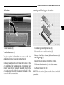
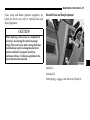
Tie Down Rings (1)
The rings (1) are used to attach the load with the help
of tension belts. Place the tension belt around the load,
secure it on the rings (1) and tie it down.
THINGS TO KNOW BEFORE STARTING YOUR VEHICLE 55
WARNING!
If you tension the tensioning belts between the
sidewalls, the maximum permissible load for the
lashing rings could be exceeded if the brakes are
applied suddenly or in the event of an accident.
The load would no longer be secured, which could
result in serious injuries caused by the load slipping.
For this reason, do not tension a tensioning belt
between the side walls.
Observe the loading guidelines.
NOTE: Use neither elastic fastening straps nor nets
when lashing down the load. These are only intended
as anti-slip protection for lighter loads.
The means used to tie down the load must not be run
over sharp edges or corners. Sharp edges or corners
should be given protective padding. Observe the
operating instructions for the material used to tie down
the material. Spread the load evenly between the
anchorages. If using a tensioning device, do not
overstress the lashing rings.
2
UNDERSTANDING THE FEATURES OF YOUR VEHICLE
CONTENTS
3
Mirror Adjustment . . . . . . . . . . . . . . . . . . . . . . . . . . 59
Interior Mirror (Optional) . . . . . . . . . . . . . . . . . . 59
Electrically Adjustable Exterior
Mirror (Optional) . . . . . . . . . . . . . . . . . . . . . . . . . 59
Seat Adjustment . . . . . . . . . . . . . . . . . . . . . . . . . . . .
Driver’s and Front Passenger’s Seat . . . . . . . . .
Lumbar Support . . . . . . . . . . . . . . . . . . . . . . . . . .
Armrest (Optional) . . . . . . . . . . . . . . . . . . . . . . . .
Head Restraint . . . . . . . . . . . . . . . . . . . . . . . . . . .
Folding Seat at Partition (Optional) . . . . . . . . .
60
60
61
62
62
63
Seat Heater (Optional) . . . . . . . . . . . . . . . . . . . . . . 63
Rear Seat Bench Removal and Installation . . . . . 64
Retrofitting Seat Mounting Cups . . . . . . . . . . . . 65
Hood . . . . . . . . . . . . . . . . . . . . . . . . . . . . . . . . . . . . . . 66
Headlamp Range Control . . . . . . . . . . . . . . . . . . . . 68
Fog Lamp Switch (Optional) . . . . . . . . . . . . . . . . . 68
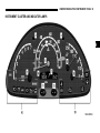
Interior Lighting . . . . . . . . . . . . . . . . . . . . . . . . . . . .
Interior Lamps in the Driver and
Rear-Seat Passenger Area/Cargo Area . . . . . . .
Interior Lamps with Interior Sensor
Protection (Optional) . . . . . . . . . . . . . . . . . . . . . .
Interior Lighting with Reading Lamp,
Front Passenger Space Only . . . . . . . . . . . . . . . .
Interior Cargo Area Lighting (Optional) . . . . .
69
69
69
70
71
Multifunction Switch . . . . . . . . . . . . . . . . . . . . . . . . 72
Window Operation . . . . . . . . . . . . . . . . . . . . . . . . . 74
Mechanical Window Operation . . . . . . . . . . . . . 74
Electric Window Operation (Optional) . . . . . . . 74
Windshield Wiper Switch . . . . . . . . . . . . . . . . . . . . 75
Windshield wipers with rain sensor
(Optional) . . . . . . . . . . . . . . . . . . . . . . . . . . . . . . . . 76
58 UNDERSTANDING THE FEATURES OF YOUR VEHICLE
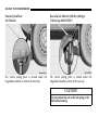
Headlamp Cleaning System (Optional) . . . . . . 77
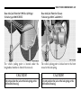
Speed Control (Optional) . . . . . . . . . . . . . . . . . . . . 77
Control and Operation of Radio Transmitters . . . 84
Radio, Telephone and Two Way Radio . . . . . . 84
80
80
81
81
Mobile and Two Way Radio and Fax Machines. . 85
Ashtray/Cigar Lighter. . . . . . . . . . . . . . . . . . . . . . . 82
Compartments in Front Doors . . . . . . . . . . . . . . . . 87
Sunroof (Optional) . . . . . . . . . . . . . . . . . . . . . . . . . .
Manual Sun Roof (Optional) . . . . . . . . . . . . . . .
Electric Sun Roof (Optional) . . . . . . . . . . . . . . . .
Mechanical Operation of Electric Sun Roof . . .
Electrical Outlet. . . . . . . . . . . . . . . . . . . . . . . . . . . . . 84
Cup Holder . . . . . . . . . . . . . . . . . . . . . . . . . . . . . . . . 85
Glove Compartment . . . . . . . . . . . . . . . . . . . . . . . . . 87
UNDERSTANDING THE FEATURES OF YOUR VEHICLE 59
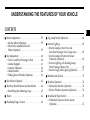
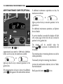
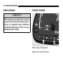
MIRROR ADJUSTMENT
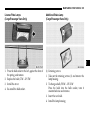
Interior Mirror (Optional)
Electrically Adjustable Exterior Mirror (Optional)
3
Normal position (DAY) (1)
The switch is located in the door lining next to the door
handle.
Anti-glare position (NIGHT) (2)
Mirror adjustment, left (1)
Mirror adjustment, right (2)
When the key is in position 2 in the ignition lock, each
mirror may be adjusted by pressing the adjustment
button.
NOTE: The exterior mirror is heated automatically
(optional equipment) when outdoor temperatures are low.
60 UNDERSTANDING THE FEATURES OF YOUR VEHICLE
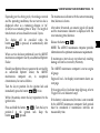
SEAT ADJUSTMENT
Driver’s and Front Passenger’s Seat
WARNING!
Do not adjust the driver’s seat while driving. Adjust the seat only while the vehicle is parked.
Adjusting the seat while driving could cause the
driver to lose control of the vehicle. The seat belt
might not be properly adjusted and you could be
injured. Avoid seat positions in which you cannot
wear your seat belt correctly. They are a safety
hazard and must therefore be avoided; refer to
"Seat Belts".
Never ride in a moving vehicle with the backrest
reclined. Sitting in an excessively reclined position
can be dangerous. You could slide under the seat
belt in a collision. If you slide under it, the belt
would apply force at the abdomen or neck as this
could result in severe personal injuries and death.
The backrest and seat belt provide the best
restraint when the wearer is in an upright position
and the belt is properly positioned on the body.
Use the recliner only when the vehicle is parked.
WARNING!
Never place hands under seat or near any moving
parts while a seat is being adjusted. If the seat is
moved, to ensure engagement, the seat catches
must be heard.
The arms should be slightly bent when you are
holding the steering wheel. The distance from the
pedals should be such that you can depress them fully.
The rear area of the vehicle should not be used as
a play area by children when the vehicle is in
motion. They could be seriously injured in an
accident. Children should be seated and using the
proper restraint system.
It is extremely dangerous to ride in a cargo area,
inside or outside of a vehicle. In a collision,
people riding in these area are more likely to be
seriously injured or killed.
Do not allow people to ride in any area of your
vehicle that is not equipped with seats and seat belts.
Be sure everyone in your vehicle is in a seat and
using a seat belt properly.
UNDERSTANDING THE FEATURES OF YOUR VEHICLE 61
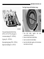
Comfortseat (Optional)
Lumbar Support
3
Seat adjustment, fore/aft (1)
Hand pump (1)
Seat cushion depth (Optional) (2)
Bleeder valve (2)
Seat height adjustment, front (3)
Reinforce support:
Seat height adjustment, rear (4)
Use hand pump (1).
Backrest tilt (5)
Relieve support:
Press bleeder valve (2).
62 UNDERSTANDING THE FEATURES OF YOUR VEHICLE
Armrest (Optional)
Head Restraint
Tilt adjustment (1)
By adjusting the tilt adjustment (thumbwheel) (1) the
tilt of the armrest can be changed.
If you need to remove the head restraint, press the
catch at the head restraint socket and pull the head
restraint up and out.
WARNING!
You should never drive the vehicle if the head restraint has been removed for an occupied seat. This
could result in severe personal injuries and death in
case of an accident. Adjust the head restraint so that
it touches the back of the head at about ear level.
UNDERSTANDING THE FEATURES OF YOUR VEHICLE 63
Folding Seat at Partition (Optional)
WARNING!
When folding down the seat cushion, make sure
that nobody can become trapped.
The risk of injury to the front-passenger is
increased in the event of sharp steering
movements or an accident if a key is inserted in
the passenger/cargo area sliding door lock.
Remove the key from the load compartment
sliding door before using the folding seat.
Key (1)
Seat cushion (2)
Fold down the seat cushion of the folding seat.
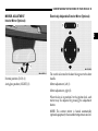
SEAT HEATER (OPTIONAL)
The seat heater switch is located on
the center section of the dashboard.
The seat heater only works when the
key is in position 2 in the ignition
lock .
Low heating output, press top of the seat heater switch.
The left indicator lamp in the switch illuminates.
High heating output, press bottom of seat heater
switch. The right indicator lamp in the switch
illuminates.
3
64 UNDERSTANDING THE FEATURES OF YOUR VEHICLE
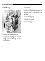
REAR SEAT BENCH REMOVAL AND
INSTALLATION
WARNING!
The integrated seat belt can only offer the degree
of protection for which it is designed if you install
the specified rear bench seats correctly. Never operate vehicle unless all rear bench seats are properly installed and all release levers are locked.
When retrofitting seat benches, make sure that the
exterior seat shells have four cross-ribs.
Keep the seat bench mounting cups in the vehicle
floor free from dirt and foreign objects. This is the
only way to guarantee that the locking
mechanisms will engage securely.
Unlocked (1)
Locked (2)
To remove:
1. Turn all release levers on the legs of the appropriate
rear bench seat up. The rear bench seat can then
move in the seat mounting cups.
2. Lift the rear bench seat up and out of the seat
mounting cups.
UNDERSTANDING THE FEATURES OF YOUR VEHICLE 65
To install:
1. With the rear bench seat facing in the direction of
travel, insert the legs of the rear bench seat in the
respective seat mounting cups on the floor.
2. Slide the rear bench seat forwards with some force
as far as it will go, until the release levers are heard
to engage and all release levers are parallel to the
vehicle floor.
3
66 UNDERSTANDING THE FEATURES OF YOUR VEHICLE
HOOD
To open:
WARNING!
When the hood is open, there is a risk of injury due
to very hot engine components.
When the engine is running or the key is in
position 2 in the ignition lock, there is a risk of
injury due to moving engine components and the
electrical system.
The engine is equipped with a transistorized
ignition system. Because of the high voltage it is
dangerous to touch any components (ignition coils,
spark plug sockets, diagnostic socket) of the
ignition system with the engine running, while
starting or if the ignition is on and the engine is
turned manually.
To help prevent severe personal injuries and death,
stay clear of moving parts when the hood is open
and the engine is running.
If you see flames or smoke coming from the engine
compartment, or if the coolant\temperature gauge
indicates that the engine is overheated, do not open
the hood. Move away from vehicle and do not open
the hood until the engine has cooled. If necessary,
call the fire department.
1. Pull the release lever (1).
The hood then opens slightly and is restrained by
the safety catch.
WARNING!
Do not pull the release lever (1) while the vehicle
is in motion. Otherwise the hood could be forced
open by passing air flow.
UNDERSTANDING THE FEATURES OF YOUR VEHICLE 67
To close:
3
2. Open the safety catch (2).
3. Swing the hood up until the support strut (3)
engages.
1. Lift the hood up slightly.
2. Press the support strut (3) down.
3. Swing the hood down and make sure that it
engages in its retaining catch.
4. Check that the hood is engaged properly by pulling
on the front edge.
68 UNDERSTANDING THE FEATURES OF YOUR VEHICLE
Where necessary, adjust the headlamp range with the
thumbwheel to 82 yards (75 m).
WARNING!
Be sure the hood is properly closed before driving.
If the hood is not fully latched, it could fly up
when the vehicle is moving and block your forward vision. Be sure all hood latches are latched
fully before driving.
When closing the hood, use extreme caution not to
catch hands or fingers.
HEADLAMP RANGE CONTROL
See Section 4, Understanding Your Instrument Panel,
for switch locations.
The range of the headlamps can be
adjusted to the load in the vehicle.
Turn the thumbwheel down to
headlamp beam down.
Turn the thumbwheel
headlamp beam up.
up
to
When the vehicle is not loaded (driver only), the
thumbwheel must be in position 0.
Always keep the headlamp range less than 110 yards
(100 m), so that oncoming traffic is not blinded.
FOG LAMP SWITCH (OPTIONAL)
See Section 4, Understanding Your Instrument Panel,
for switch locations.
Lamp switch position õ
To switch on:
Press the upper section of the switch.
To switch off:
Press the lower section.
UNDERSTANDING THE FEATURES OF YOUR VEHICLE 69
INTERIOR LIGHTING
Interior Lamps in the Driver and Rear-Seat
Passenger Area/Cargo Area
Interior Lamps with Interior Sensor Protection
(Optional)
3
Interior lamp switch (1)
Permanently on (1)
Off (2)
Interior lamps are switched on/off by the door contact
switches (3)
Reading lamp switch (2)
70 UNDERSTANDING THE FEATURES OF YOUR VEHICLE
Operation of Interior Lamps
Position 1: Continuous operation
Interior Lighting with Reading Lamp, Front
Passenger Space Only
Position 2: The door contact switches
are used to switch the interior lamps
on and off
Position 3: Switched off
Operation of Reading Lamps
Position 1: Left-hand reading lamp switched on
Position 2: Switched off
Position 3: Right-hand reading lamp switched on
Continuous operation (1)
The door contact switches are used to switch the
interior lamps on and off (2)
Switched off (3)
Reading lamp (4)
UNDERSTANDING THE FEATURES OF YOUR VEHICLE 71
Interior Cargo Area Lighting (Optional)
The switch is located on the center
section of the dashboard.
To switch on:
3
Press top of switch:
The indicator lamp in the switch will
illuminate.
To switch off:
Press bottom of switch.
The switch (1) is located on the right side of the cargo
area at the entrance for the sliding door.
To switch on:
Press top of switch – the indicator lamp in the switch
will illuminate.
To switch off:
Press bottom of switch.
72 UNDERSTANDING THE FEATURES OF YOUR VEHICLE
MULTIFUNCTION SWITCH
The switch (2) is located in the right rear of the cargo
area.
Turn signal indicator lamp, right (1)
To switch on:
Turn signal indicator lamp, left (2)
Press top of switch, the indicator lamp in the switch
will illuminate.
Short turn signal, press combination switch to pressure
point.
To switch off:
Continuous turn signal, engage combination switch.
Press bottom of switch.
If a turn signal on the vehicle fails, the indicator lamp
in the instrument cluster flashes at twice the normal
rate.
NOTE: The interior cargo area lighting will shut off
automatically after 15 min.
UNDERSTANDING THE FEATURES OF YOUR VEHICLE 73
High beam headlamps (lamp switch positionõ) (4)
Headlamp flasher (also when turn signals are on) (5)
NOTE: When the key is in the ignition lock in the 0
position and the driver’s or passenger’s door is open, a
warning buzzer sounds, if the vehicle exterior lighting
(except for the marker lamps) has been switched on.
On vehicles with automatic switching-off of high
beam, with the key in 0 position and the lamp switch
position õ on low and high beam, parking lamps
are automatically switched on. When the driver’s or
passenger’s door is opened, a warning buzzer also
sounds.
Lamp switch (3)
C Side lamps, license plate and instrument
lighting
õ Low beam
headlamps
headlamps,
high
beam
ƒ Marker lamps, right, combination switch
up (1)
Marker lamps, left, combination switch
down (2)
For high beam (4) and headlamp flasher (5), the
indicator lamp A in the combination instrument
lights up.
3
74 UNDERSTANDING THE FEATURES OF YOUR VEHICLE
Electric Window Operation (Optional)
The window operation switches are
located on the driver’s and frontpassenger doors.
WINDOW OPERATION
Mechanical Window Operation
WARNING!
Make certain that no one gets caught when the
side windows are closed.
To open the window:
Turn the manual window
counterclockwise direction.
control
in
a
To close the window:
Turn the manual window control in a clockwise
direction.
The key should be removed from the ignition lock
even if the vehicle will only be left for a short time
to prevent situations such as children or
unauthorized persons opening and closing the
windows and becoming caught.
UNDERSTANDING THE FEATURES OF YOUR VEHICLE 75
Place the key in position 2 in the ignition lock.
WINDSHIELD WIPER SWITCH
To open the window:
Keep switch pressed downward until the window has
reached the desired position.
3
To close the window:
Keep switch pressed upward until the window has
reached the desired position.
Intermittent wipe and rain sensor (optional) (1)
Normal wipe (2)
Rapid wipe (3)
Windshield wiper system and headlamp cleaning
system (optional) (4)
76 UNDERSTANDING THE FEATURES OF YOUR VEHICLE
WARNING!
Sudden loss of visibility through the windshield
caused by e. g. ice, steam, fog or water could lead
to an accident. You might not see other vehicles or
other obstacles. To avoid sudden icing of the
windshield during freezing weather, warm the
windshield with the defroster or with the windshield heater (optional) before and during windshield washer use.
Follow the recommended settings for de-fogging
and de-icing the front windows given in Section 4.
Touch-wipe:
Press the windshield wiper switch up to the pressure
point.
NOTE: Smears may form on the glass when the
windshield wipers are in use. In this case, operate the
windshield washer, even in rainy weather.
Check wiper blades regularly for damage and
contamination.
Windshield wipers with rain sensor (Optional)
To switch on:
Turn the windshield wiper switch to Intermittent
wipe.
When switched on, the windshield wipers wipe one
time. After that the wiping interval and wiping speed
(normal and rapid), depend on wetness of the
windshield and are controlled automatically.
CAUTION!
Do not leave windshield wipers in intermittent
setting when vehicle is taken to an automatic car
wash or during windshield cleaning and/or deicing. Wipers will operate if the windshield gets
wet, and wipers may be damaged as a result.
UNDERSTANDING THE FEATURES OF YOUR VEHICLE 77
Headlamp Cleaning System (Optional)
The headlamps will be cleaned with a high-pressure
water jet when
SPEED CONTROL (OPTIONAL)
• the headlamps are switched on
3
and
• the windshield wipers operate with washer fluid.
NOTE: Fluid for the headlamp cleaning system is also
supplied from the washer system fluid reservoir.
Set/accelerate speed (1)
Set/decelerate speed (2)
Off (3)
Resume set speed (4)
78 UNDERSTANDING THE FEATURES OF YOUR VEHICLE
The speed control allows you to drive in a more
relaxed manner, for example over long distances, as it
automatically maintains the set speed by actively
regulating the throttle setting.
The speed control lever on the steering column is used
to activate and operate the speed control.
NOTE: The responsibility for the driving speed is
always that of the driver. The cruise control is only an
aid for the driver.
NOTE: A change of gear does not shut off the cruise
control.
Every speed traveled above 25 mph (40 km/h) can be
set.
Once the speed is set, it is maintained constant by the
speed control, the accelerator pedal can be released.
WARNING!
Leaving the Speed Control on when not in use is
dangerous. You could accidently set the system or
cause it to go faster than you want. You could lose
control and have an accident. Always turn the
system off when you are not using it.
Setting momentary speed
Briefly push speed control lever up (1) or down (2).
Cancel speed control
Push speed control lever forwards (3) or step on the
brake pedal.
Increase set speed
Push up speed control lever (1) briefly – speed increase
of 0.6 mph (1 km/h) each time.
To increase speed steadily = hold the speed control
lever in the push-up position.
UNDERSTANDING THE FEATURES OF YOUR VEHICLE 79
Decrease set speed
Push down speed control lever (2) briefly – speed
decrease of 0.6 mph (1 km/h) each time.
To decrease speed steadily, hold the speed control
lever in the push-down position.
Resume set speed (after shutting off)
Push speed control lever back (4).
With the accelerator pedal the set speed can be
increased (for passing).
When the accelerator pedal is released again, the set
speed regulates itself again.
With the key in position 0 or 1 in the ignition lock the
set speed is cancelled.
WARNING!
The speed control does not adapt itself automatically to road conditions; therefore do not use
cruise control on icy roads. There is a risk of skidding and loss of vehicle control. This could cause
an accident resulting in severe personal injuries,
death and property damage.
NOTE: On uphill and downhill grades it may not be
possible to maintain set speed.
3
80 UNDERSTANDING THE FEATURES OF YOUR VEHICLE
SUNROOF (OPTIONAL)
Manual Sun Roof (Optional)
WARNING!
In an accident, there is a greater risk of being
thrown from a vehicle with an open sun roof. You
could also be seriously injured or killed. Always
fasten your seatbelt properly and make sure all
passengers are properly secured too.
Do not allow small children to operate the electric
sun roof.
Never allow fingers or other body parts, or any
object to project through the sun roof opening.
Injury may result.
Make certain that no one gets caught when the
electric sun roof is closed. The key should be
removed from the ignition lock even if the vehicle
will only be left for a short time to prevent
situations such as children or unauthorized
persons opening and closing the electric sun roof
and becoming caught.
• To open, turn the handwheel counterclockwise.
Maximum opening = turn until the stop is reached.
• To close, turn the handwheel clockwise until the
stop is reached.
UNDERSTANDING THE FEATURES OF YOUR VEHICLE 81
WARNING!
Never allow fingers or other body parts, or any object to project through the sun roof opening. Injury may result.
Make sure that nobody can be trapped when
closing the sun roof.
Electric Sun Roof (Optional)
See Section 4, Understanding Your Instrument Panel,
for switch locations.
Place the key in position 2 in the
ignition lock.
To open the electric sun roof:
Keep switch pressed upward until
the sun roof has reached the desired
position or the end position.
To close the electric sun roof:
Keep switch pressed downward until the sun roof has
reached the desired position or is completely closed.
Mechanical Operation of Electric Sun Roof
The sun roof does not open or close:
Check electrical fuse. Electrical fuses refer to “Electrical
Fuses“.
If the fuse works correctly, the sun roof can also be
closed or opened manually.
3
82 UNDERSTANDING THE FEATURES OF YOUR VEHICLE
ASHTRAY/CIGAR LIGHTER
Remove cover (1) at the front frame of the sun roof.
Remove tool (2) from the cover (1) and insert.
Open manually:
Press in tool (2) and turn counterclockwise (3).
Close manually:
Press in tool (2) and turn clockwise (4).
Have malfunctions rectified by an authorized Sprinter
Dealer.
Ashtray in the driver’s compartment.
Ashtray (1)
Cigar lighter (2)
UNDERSTANDING THE FEATURES OF YOUR VEHICLE 83
To open the ashtray (1):
Ashtray in the rear passenger compartment.
Pull the ashtray (1) out until it locks into place.
To close the ashtray (1):
3
Push the ashtray (1) forward over the working point
until it reaches the stop.
To switch on the cigar lighter (2):
Press in the cigar lighter (2),
it will automatically spring back as soon as the filament
begins to glow.
The ashtrays are located in the side linings in the
passenger compartment.
84 UNDERSTANDING THE FEATURES OF YOUR VEHICLE
ELECTRICAL OUTLET
The electrical outlet is located on the
lower right in the center of the
dashboard.
NOTE: Maximum capacity: 180 VA
CAUTION!
• Many accessories that can be plugged in draw
power from the vehicle’s battery, even when not
in use (i.e. cellular phones, etc.). Eventually, if
plugged in long enough, the vehicle’s battery
will discharge sufficiently to degrade battery life
and/or prevent engine starting.
• Accessories that draw higher power (i.e., coolers,
vacuum cleaners, lights, etc.), will degrade the
battery even more quickly. Only use these
intermittently and with greater caution.
• After the use of high power draw accessories, or
long periods of the vehicle not being started (with
accessories still plugged in), the vehicle must be
driven a sufficient length of time to allow the
alternator to recharge the vehicle’s battery.
CONTROL AND OPERATION OF RADIO
TRANSMITTERS
Radio, Telephone and Two Way Radio
WARNING!
Please do not forget that your primary responsibility is to drive the vehicle. Only operate the radio, telephone, navigation system, two-way radio
or fax when road and traffic conditions permit.
Otherwise you could be distracted from the traffic
and cause an accident. Always obey local laws and
regulations.
Remember that at a speed of just 30 mph (about 50
km/h), your vehicle is covering a distance of 50
feet (about 14 m) every second.
UNDERSTANDING THE FEATURES OF YOUR VEHICLE 85
MOBILE AND TWO WAY RADIO AND FAX
MACHINES
WARNING!
Never operate radio transmitters equipped with a
built-in or attached antenna (i.e., without being
connected to an external antenna) from inside the
vehicle while the engine is running. Doing so
could lead to a malfunction of the vehicle’s electronic system, possibly resulting in severe personal injuries and death.
Radio transmitters, such as a mobile phone or a citizens
band unit should only be used inside the vehicle they
are connected to an antenna that is installed on the
outside of the vehicle.
Refer to the radio transmitter operation instructions
regarding use of an external antenna.
CUP HOLDER
The cup holder in the driver’s compartment is located
below the instrument panel between the driver’s and
front passenger’s seats.
3
86 UNDERSTANDING THE FEATURES OF YOUR VEHICLE
The cup holders in the passenger compartment are
located in the center below the seat benches.
WARNING!
Your primary responsibility is to drive the vehicle.
Do not use cup holder while the vehicle is in
motion. Otherwise you could be distracted from
traffic and cause an accident or liquid could spill
from the containers due to for example breaking
or other vehicle movement.
Place only containers that fit into the cup holder to
prevent spills.
Do not fill containers to a height where the
contents could spill, especially hot liquids.
Otherwise you may scald yourself.
Pull out cup holder in the direction of arrow.
UNDERSTANDING THE FEATURES OF YOUR VEHICLE 87
GLOVE COMPARTMENT
COMPARTMENTS IN FRONT DOORS
3
To open glove compartment:
Pull handle (1)
Locked (1)
Unlocked (2)
UNDERSTANDING YOUR INSTRUMENT PANEL
CONTENTS
Instruments and Controls . . . . . . . . . . . . . . . . . . . . 91
Switch Locations . . . . . . . . . . . . . . . . . . . . . . . . . . . 110
Instrument Cluster and Indicator Lamps . . . . . . . 93
Indicator Lamp Symbols . . . . . . . . . . . . . . . . . . . 95
Multi-Function Indicator . . . . . . . . . . . . . . . . . . . 96
Clock . . . . . . . . . . . . . . . . . . . . . . . . . . . . . . . . . . . 98
Odometer and Trip Meter . . . . . . . . . . . . . . . . . . 99
Instrument and Display Lighting . . . . . . . . . . . 99
Outside Temperature Display . . . . . . . . . . . . . 100
Reversing Aid Distance Display (Optional) . . 101
Tachometer (Engine rpm) . . . . . . . . . . . . . . . . . 103
Coolant Temperature Gauge . . . . . . . . . . . . . . 103
Fuel Gauge with Reserve Fuel
Indicator Lamp . . . . . . . . . . . . . . . . . . . . . . . . . . 105
Battery Charge Indicator Lamp . . . . . . . . . . . . 106
Water in Fuel Indicator Lamp . . . . . . . . . . . . . 106
Engine Oil Level Indicator Lamp . . . . . . . . . . . 107
Coolant Level Indicator Lamp . . . . . . . . . . . . . 108
Engine Control Unit Indicator Lamp . . . . . . . 109
ASSYST Maintenance Computer (Optional). . . . 112
Engine Oil Level – Display in Instrument
Cluster (Vehicles with ASSYST Maintenance
Computer only) . . . . . . . . . . . . . . . . . . . . . . . . . 114
Displaying Engine Oil Level with
Engine Off . . . . . . . . . . . . . . . . . . . . . . . . . . . . . . 115
Engine Oil Level Indicator in Instrument
Cluster (Vehicles without ASSYST
Maintenance Computer) . . . . . . . . . . . . . . . . . . . . 117
Heating, Ventilation . . . . . . . . . . . . . . . . . . . . . . . .
Ventilation . . . . . . . . . . . . . . . . . . . . . . . . . . . . . .
Air Recirculation . . . . . . . . . . . . . . . . . . . . . . . . .
Heating . . . . . . . . . . . . . . . . . . . . . . . . . . . . . . . . .
De-Fogging and De-Icing The Front
Windows . . . . . . . . . . . . . . . . . . . . . . . . . . . . . . .
Side Air Vents and Center Air Vents . . . . . . . .
118
119
119
120
121
122
4
90 UNDERSTANDING YOUR INSTRUMENT PANEL
Upper Air Vents . . . . . . . . . . . . . . . . . . . . . . . . .
Heated Rear Window (Optional) . . . . . . . . . . .
Windshield Heater (Optional) . . . . . . . . . . . . .
Residual Engine Heat Utilization (REST) . . . .
122
123
123
124
Air Conditioning, Regulated (Optional) . . . . . .
Climate Control (on Vehicles with
Air Conditioning) . . . . . . . . . . . . . . . . . . . . . . . .
Dehumidification
(on Vehicles with Air Conditioning) . . . . . . . .
Air Conditioner for the Rear Passenger
Compartment (Optional) . . . . . . . . . . . . . . . . .
Air Recirculation . . . . . . . . . . . . . . . . . . . . . . . .
Air Strainer . . . . . . . . . . . . . . . . . . . . . . . . . . . . .
124
125
Heater Booster . . . . . . . . . . . . . . . . . . . . . . . . . . . . . 131
Auxiliary Heater – Water or Air Heater
(Optional) . . . . . . . . . . . . . . . . . . . . . . . . . . . . . . . . .
Auxiliary Heater Switch . . . . . . . . . . . . . . . . . .
Timer Auxiliary Heater . . . . . . . . . . . . . . . . . . .
Settings with the Auxiliary Heater
switched on . . . . . . . . . . . . . . . . . . . . . . . . . . . . .
132
134
134
138
126
Auxiliary Heat Exchanger in Load Compartment,
only with Auxiliary Heater (Optional) . . . . . . . . 139
127
128
129
Auxiliary Heater – Tips for Coping
with Problems . . . . . . . . . . . . . . . . . . . . . . . . . . . . . 140
Overheating . . . . . . . . . . . . . . . . . . . . . . . . . . . . . 140
Electric Blower (Optional) . . . . . . . . . . . . . . . . . . . 130
UNDERSTANDING YOUR INSTRUMENT PANEL 91
INSTRUMENTS AND CONTROLS
4
92 UNDERSTANDING YOUR INSTRUMENT PANEL
Legend For Instruments And Controls
1. Left-hand air vent.
14. Temperature control switch.
2. Multifunction switch.
16. Air distribution switch.
3. Speed control.
17. Temperature sensor, automatic heating
control/air conditioning, regulated.
4. Hood release lever.
15. Airflow control switch.
18. Air conditioning switch.
5. Instrument cluster, refer to "Instrument Cluster
and Indicator Lamps".
19. Heater booster switch.
6. Hazard warning flasher switch.
20. Residual engine heat utilization switch.
7. Steering wheel with horn, front driver airbag.
21. Gear selector lever (automatic transmission)
8. Fuse box.
22. Timer for auxiliary heater.
9. Windshield wiper switch, refer to "Windshield
Wiper Switch".
23. Electrical outlet.
10. Ignition lock/starter switch.
11. Center air vents.
12. Upper air vents.
13. Radio, see individual manual.
24. Ashtray.
25. Cup holder.
26. Front passenger airbag.
27. Right-hand air vent.
28. Glove compartment.
NOTE: For layout of switches, see previous page.
UNDERSTANDING YOUR INSTRUMENT PANEL 93
INSTRUMENT CLUSTER AND INDICATOR LAMPS
4
94 UNDERSTANDING YOUR INSTRUMENT PANEL
Legend For Instrument Cluster And Indicator Lamps
1. Tachometer (Engine rpm), refer to "Tachometer
(Engine rpm)".
2. Turn signal indicator lamp (left), refer to
"Multifunction Switch".
3. Turn signal indicator lamp (right), refer to
"Multifunction switch".
4. ASR warning lamp or ESP®* warning lamp.
5. Speedometer.
6. Multi-function indicator, refer to "Multi-Function
Indicator".
7. Gear selector lever position.
8. Coolant temperature gauge, refer to "Coolant
Temperature Gauge".
* 2500 Type vehicles only
9. Fuel gauge with reserve fuel indicator lamp
(yellow), refer to "Fuel Gauge with Reserve Fuel
Indicator Lamp".
10. Warning and indicator lamps.
11. Odometer/trip meter selector, refer to "Odometer
and Trip Meter".
Clock/outside temperature display selector, refer
to "Clock and Outside Temperature Display".
12. Instrument lighting brighter/dimmer, refer to
"Instrument Lighting".
UNDERSTANDING YOUR INSTRUMENT PANEL 95
Indicator Lamp Symbols
v
1
Acceleration skid control (ASR)
or electronic stability program (ESP®)*
or slippery surface warning.
Airbag Malfunction (USA only).
Parking brake applied.
A
#
High beam on, refer to "Multifunction Switch".
Battery not being charged,
refer to "Battery Charge Indicator Lamp".
Water in fuel filter, refer to "Water in Fuel
Indicator Lamp".
2
:
Brake pads worn.
/
Coolant level too low,
refer to "Coolant Level Indicator Lamp".
;
Brake fluid level too low and electronic brake force
distribution (EBD) malfunction (USA only).
Engine oil level too low,
refer to "Engine Oil Level Indicator Lamp".
*2500 Type Vehicles only.
3
Brake fluid level too low and electronic brake force
distribution (EBD) malfunction (Canada only).
<
#
Seat belt warning lamp.
±
Engine control unit malfunction.
k
Acceleration skid control (ASR) malfunction
and brake assist system (BAS)1 malfunction.
™
W
q
Constant RPMs on.
Anti-lock brake system (ABS) malfunction.
Electronic stability program (ESP®)* malfunction.
Fluid level in windshield washer low.
Preheating.
4
96 UNDERSTANDING YOUR INSTRUMENT PANEL
Multi-Function Indicator
WARNING!
Never operate buttons (1, 2, 3 and 4) in the multifunction indicator while driving.
To operate these buttons the driver must reach
through the steering wheel, which could
significantly impede its movement.
Your attention will also be diverted from the road
and traffic conditions.
This could cause you to lose control of the vehicle
and could lead to an accident and result in severe
personal injuries or death.
For this reason, make sure that the traffic
conditions are safe before pressing the buttons, so
that nobody may be endangered.
When possible, reach around the steering wheel
to operate the multi-function indicator buttons.
Do not rest your head or chest on the steering
wheel or dashboard when operating the buttons.
UNDERSTANDING YOUR INSTRUMENT PANEL 97
The multi-function indicator can be used to call up the
odometer, trip meter, clock and outside temperature,
or information such as remaining time/distance until
the next service is due, or the engine oil level.
If your vehicle is equipped with reversing aid, the
multi-function indicator also displays the distance
between your vehicle and a detected obstacle.
The multi-function indicator is activated by:
Turning the key to position 2 in the ignition lock,
opening the driver’s door,
pressing one of the buttons
æ,
(‘), I, ç or
switching the side lights on, refer to "Combination
Switch".
1. Press the button
(‘) to switch between the
odometer and the trip meter, and to reset the trip
meter.
Press the button
(‘) to activate the ASSYST
maintenance computer.
2. Press the I button to switch between the time
and outside temperature and to activate the time
adjustment.
3. Press the ç to adjust (dim) the display and
instrument lighting and to adjust the clock.
4. Press the æ to adjust (brighten) the display and
instrument lighting and to adjust the clock.
4
98 UNDERSTANDING YOUR INSTRUMENT PANEL
Clock
To switch between Time and Outside Temperature
Display (Optional)
Press the I button briefly.
If button I is pressed twice within one second, the
display will revert to the original mode after
20 seconds.
To Adjust the Time
Call up time display:
Activate the multi-function indicator, refer to "MultiFunction Indicator".
Button I – to reverse the time adjustment/
switch between hours and minutes (1)
Button ç – to turn the time back (2)
Button æ – to advance the time (3)
1. Press button I and hold – the hours display will
flash.
To change the time by one hour = briefly press
button æ or ç.
To change the time by several hours = press and
hold button æ or ç.
2. Briefly press button I – the minutes display will
flash.
To change the time by one minute = briefly press
button æ or ç.
To change the time by several minutes = press and
hold button æ or ç.
3. Briefly press button I – the set time is accepted.
UNDERSTANDING YOUR INSTRUMENT PANEL 99
Odometer and Trip Meter
Instrument and Display Lighting
4
Activate the multi-function indicator. The total
distance covered by the vehicle will be shown.
Display lighting:
1. To switch between the odometer and the trip meter,
press button (1) briefly.
2. To reset the trip meter, call up trip meter. Press
button (1) and hold until the trip meter shows 0000.
4. Press button æ, to display lighting brighter
NOTE: Odometer and trip meter display
–
"mi" in USA only.
–
"km" in Canada only.
3. Press button ç, to display lighting dimmer
100 UNDERSTANDING YOUR INSTRUMENT PANEL
Instrument and display lighting:
1. Switch on the marker lamps, refer to "Combination
Switch"
2. Press button ç, to make instrument and display
lighting dimmer
3. Press button æ, to make instrument display
lighting brighter
Outside Temperature Display
Clock/outside temperature display selector (1)
Press button I briefly. The display will switch to
the required mode.
If button I is pressed twice within one second, the
display will revert to the original mode after
20 seconds.
UNDERSTANDING YOUR INSTRUMENT PANEL 101
The outside temperature is displayed when the multifunction indicator is activated. Sudden changes in
temperature, for instance when leaving a garage, are
only shown after a certain delay.
NOTE: Outside temperature display
°F in USA only.
in
°C in Canada only.
WARNING!
Even if the display still reads a few degrees above
32°F (0°C), the road surface may be icy, particularly in woods or on bridges. You could skid and lose
control over your vehicle and thereby cause an accident.
Adapt your speed and driving style to the
prevailing road and weather conditions to prevent
an accident and possible personal injury or
property damage.
Reversing Aid Distance Display (Optional)
When the key is in position 2 in the ignition lock and
the reverse gear is engaged, the reversing aid
automatically begins to monitor the area to the rear of
the vehicle.
4
102 UNDERSTANDING YOUR INSTRUMENT PANEL
The following display appears if the reversing aid does
not detect an obstacle.
When a continuous warning signal sounds for
approximately three seconds and the error code
NOTE: Distance display
appears in the multi-function indicator, the reversing
aid is malfunctioning.
• "in" in USA only.
• "cm" in Canada only.
The distance between the sensors and an obstacle
detected within the monitoring range is displayed in
increments of 2 in (5 cm).
Maneuver with particular care, if interference from an
external source of ultrasonic waves (compressed-air
brakes of trucks, a car wash or a pneumatic drill) is
causing the reversing aid to malfunction.
If the distance is less than 40 in (100 cm), a warning
signal also sounds, which is repeated increasingly
frequently as the vehicle approaches the obstacle.
Dirty reversing aid sensors or malfunctioning backup
lamps could also cause the reversing aid to
malfunction. Clean the reversing aid sensors and check
the backup lamps.
A continuous warning signal sounds if the distance
undershoots 20 in (50 cm).
Otherwise have the malfunction traced and rectified by
an authorized Sprinter Dealer.
UNDERSTANDING YOUR INSTRUMENT PANEL 103
Tachometer (Engine rpm)
Coolant Temperature Gauge
4
Do not exceed the maximum permissible engine speed.
NOTE: To protect the engine, its fuel supply is
interrupted when the maximum rpm is reached.
Despite this, the maximum rpm can still be exceeded in
overrun mode (e.g. when driving downhill).
The coolant temperature is displayed when the key is
in position 2 in the ignition lock.
If corrosion inhibitor/antifreeze is present in the
correct concentration in the coolant, the coolant
temperature will be between 185 °F (+85 °C) and
250 °F (+120 °C), depending on operating conditions.
If the needle reaches the red section, do not continue to
drive the vehicle.
104 UNDERSTANDING YOUR INSTRUMENT PANEL
CAUTION!
WARNING!
Do not leave your vehicle unattended with the
engine running as you would not be able to react to
the temperature indicator if the engine overheats.
This would lead in turn to engine damage.
Driving when your engine is badly overheated
can cause some fluids which may have leaked into
the engine compartment to catch fire. You could
be seriously burned. Steam from an overheated
engine can cause serious burns and can occur just
by opening the engine hood. Stay away from the
engine if you see or hear steam coming from it.
Turn off the engine, get out of the vehicle and do
not stand near the vehicle until it cools down.
For coolant level indicator lamp /, refer to "Coolant
Level Indicator Lamp".
NOTE: Coolant temperature display
°F in USA only.
°C in Canada only.
UNDERSTANDING YOUR INSTRUMENT PANEL 105
Fuel Gauge with Reserve Fuel Indicator Lamp
The reserve fuel indicator lamp (1) lights up for
about 2 seconds.
If the reserve fuel indicator lamp remains on or lights
up again when the engine is running, the fuel in the
tank hasreached reserve level.
Reserve level: about 2.8 US gal (10.5 liters).
NOTE: If the fuel gauge sensor is damaged, the reserve
fuel indictor lamp (1) will light up and the needle will
vary its position between the maximum and minimum
marks. Have the malfunction traced and rectified by an
authorized Sprinter Dealer.
The fuel level is displayed when the key is in position
2 in the ignition lock.
4
106 UNDERSTANDING YOUR INSTRUMENT PANEL
Battery Charge Indicator Lamp
Water in Fuel Indicator Lamp
When the key is in position 2 in the ignition lock, the
battery charge indicator lamp # will light up in the
instrument cluster. It must go out when the engine is
running.
When the key is turned to position 2 in the ignition
lock, the fuel filter indicator lamp
in the
instrument cluster lights up for about 2 seconds. It
must go out when the engine is running.
If the battery charge indicator lamp # remains on or
lights up again while the vehicle is moving, a fault has
developed in the battery charge circuit.
If water in fuel indicator lamp
does not go out or
comes on with the engine running, drain the water
from the fuel filter as soon as possible.
Do not drive on. Take your vehicle to an authorized
Sprinter Dealer to have the problem corrected.
UNDERSTANDING YOUR INSTRUMENT PANEL 107
NOTE: Should the water in fuel indicator lamp
still not go out after the fuel filter has been drained, the
cause should be examined by an authorized Sprinter
Dealer.
Engine Oil Level Indicator Lamp
If the indicator lamp
does not light up for about
2 seconds with the key in the ignition lock in position 2,
there is a malfunction in the water separator system.
Have the cause rectified by an authorized Sprinter
Dealer.
4
The engine oil level indicator lamp : lights up in
the instrument cluster when the key is turned to
position 2 in the ignition lock. It must go out when the
engine is running.
108 UNDERSTANDING YOUR INSTRUMENT PANEL
If the engine oil level indicator lamp : does not go
out, or if it lights up again while the vehicle is moving,
the engine oil level has dropped to a point close to the
minimum level mark on the dipstick.
Coolant Level Indicator Lamp
The indicator lamp : lights up only briefly at first,
becoming permanent as the oil level drops further.
Stop the engine immediately and check the engine oil
level. If no obvious leak is visible, correct the oil level.
If the engine oil level indicator lamp : lights up,
even if the engine oil level is sufficient, have the cause
traced and rectified by an authorized Sprinter Dealer.
For approved engine oils, please contact your
authorized Sprinter Dealer.
When the key is turned to position 2 in the ignition
lock, the coolant level indicator lamp / in the
instrument cluster lights up for about 2 seconds. It
must go out when the engine is running.
If the coolant level indicator lamp / remains on or
lights up again when the engine is running, the coolant
level is too low.
Do not drive on. Switch the engine off and add coolant.
UNDERSTANDING YOUR INSTRUMENT PANEL 109
If a large quantity of coolant is being lost, or if smaller
amounts are lost at regular intervals, have the engine
cooling system examined by an authorized Sprinter
Dealer.
Engine Control Unit Indicator Lamp
CAUTION!
4
Never run the engine if the coolant level is too
low. This could cause the engine to overheat,
leading in turn to engine damage.
WARNING!
Driving when your engine is badly overheated
can cause some fluids which may have leaked into
the engine compartment to catch fire. You could
be seriously burned. Steam from an overheated
engine can cause serious burns and can occur just
by opening the engine hood. Stay away from the
engine if you see or hear steam coming from it.
Turn off the engine, get out of the vehicle and do
not stand near the vehicle until it cool downs.
When the key is in position 2 in the ignition lock, the
engine control unit indicator lamp ± will light up in
the instrument cluster. It must go out when the engine
is running.
If the engine control unit indicator lamp ± remains on
or lights up again while the vehicle is moving, the fuel tank
was run empty or a fault has developed in the engine
control unit. The engine’s power output may be reduced.
Refuel and bleed the fuel system or have the cause
traced and rectified by an authorized Sprinter Dealer.
110 UNDERSTANDING YOUR INSTRUMENT PANEL
SWITCH LOCATIONS
UNDERSTANDING YOUR INSTRUMENT PANEL 111
Legend for Switch Locations
1. Fog lamp switch (Optional), refer to "Fog Lamp
Switch".
2. Headlamp range control, refer to "Headlamp
Range Control".
3. Auxiliary heat exchanger switch (Optional).
4. Heated rear window (Optional).
5. Left-hand seat heater switch (Optional).
6. Central locking switch with load compartment lock
(Optional).
9. Switch for auxiliary heater (Optional)
10. Right-hand seat heater switch (Optional),
11. Sun roof operation switch (Optional).
12. Interior cargo area lighting (Optional),
refer to "Interior Cargo Area Lighting".
13. Towing/passenger compartment protection switch
(Optional).
14. Airflow switch for the air conditioner for rear
passenger compartment (Optional).
15. Temperature control (Optional).
7. Alarm pushbutton.
16. Electric blower switch (Optional).
8. Deactivate Acceleration skid control (ASR) switch.
17. Windshield heater switch (Optional).
18. Constant RPM switch (Optional).
4
112 UNDERSTANDING YOUR INSTRUMENT PANEL
ASSYST MAINTENANCE COMPUTER (OPTIONAL)
If additional maintenance operations are due, the
maintenance indicator
Symb
Symb
or
N00.00-2388-00
N00.00-2157-00
lights up when the key is turned to position 2 in the
ignition lock.
For additional maintenance operations, see Sprinter
Service Booklet.
If a service deadline is exceeded, the display will flash
with a minus sign in front when the key is turned to
position 2 in the ignition lock.
Function button
(‘) (1)
Approximately one month or 2,000 miles (3,000 km)
before a service is due, the maintenance symbol
Symb
Symb
or
N00.00-2387-00
N00.00-2156-00
The display will be cancelled when the
button
(‘) is pressed, or automatically after
10 seconds.
The remaining time or remaining distance can also be
called up manually.
To manually call up the remaining time/distance:
lights up when the key is turned to position 2 in the
ignition lock.
Activate the multi-function indicator, refer to "MultiFunction Indicator".
If the remaining time (in days) is shown, the additional
symbol È also appears in the multi-function indicator.
Briefly press the button
(‘) twice.
UNDERSTANDING YOUR INSTRUMENT PANEL 113
Depending on the driving style, the mileage covered
and the operating conditions, the next service due is
displayed either as a remaining distance in "mi"
(in km) or as a remaining time in "days". The length of
time between services should not exceed 2 years.
The display will be cancelled when the
button
(‘) is pressed, or automatically after
10 seconds.
When a service has been performed, have the ASSYST
maintenance computer reset by an authorized Sprinter
Dealer.
Should your Sprinter for any reason not be serviced by
an authorized Sprinter Dealer, the ASSYST
maintenance
computer
can,
in
exceptional
circumstances, be reset as follows:
Turn the key to position 2 in the ignition lock and
immediately press the button
(‘) twice.
Within 10 seconds, return the key to position 0 in the
ignition lock.
Press and hold the button
(‘). Turn the key to
position 2 in the ignition lock. Keep the
button
(‘) pressed.
The maintenance indicator with the current remaining
time/distance is shown.
After about 10 seconds, an acoustic signal will sound
and the maintenance indicator is displayed with the
new remaining time/distance.
Release the button
(‘).
NOTE: The ASSYST maintenance computer provides
information on the optimum maintenance requirements.
If maintenance intervals are not observed, resulting
damage will not be covered by Warranty.
The ASSYST maintenance computer is not an engine
oil gauge.
Engine oil level – for display in instrument cluster, see
next page.
If the engine oil level indicator lamp lights up, refer to
"Engine Oil Level Indicator Lamp".
If the battery is disconnected, the time is not recorded
by the ASSYST maintenance computer. Such periods
must be considered if maintenance intervals are
measured by time.
4
114 UNDERSTANDING YOUR INSTRUMENT PANEL
Engine Oil Level – Display in Instrument Cluster
(Vehicles with ASSYST Maintenance Computer only)
If no engine oil is added and the engine oil level drops
further, a warning buzzer will also sound and
qt
Symb
N00.00-2384-00
will appear in the multi-function indicator. 2.0 quarts
(about 1.9 liters) of oil must be added.
NOTE: Engine oil level display
– "qt" in USA only.
– "l" in Canada only.
CAUTION!
If the : indicator lamp lights up briefly when the
engine is running, the engine oil level has dropped to
the minimum mark. Check the engine oil level without
delay and add oil to the upper mark on the dipstick.
If the : indicator lamp lights up, the warning
symbol in the multi-function indicator appears
and the warning buzzer sounds, the operating
safety of the engine is endangered (possibility of
engine damage).
A sudden decrease or absence of oil pressure may
indicate a mechanical failure. Bring the vehicle to
a safe stop, and investigate the cause to prevent
further damage. Do not operate the engine until
the cause has been determined and corrected.
UNDERSTANDING YOUR INSTRUMENT PANEL 115
If the warning
Symb
N00.00-2150-00
Displaying Engine Oil Level with Engine Off
is displayed in the multi-function indicator while the
engine is running, the engine oil level is above
maximum.
4
CAUTION!
Do not operate the engine if the oil level is above
maximum. There is a danger of damage to the
engine or catalytic converter.
Siphon or drain off engine oil until the engine oil level
is between the lower and upper marks on the dipstick.
Check the engine oil level again.
Symb
N00.00-2151-00
If the engine has reached normal operating
temperature, the engine oil level can be displayed on
the multi-function indicator for about 5 minutes after
the engine has been switched off.
must be displayed.
The vehicle must be standing on a level surface when
the engine oil is being checked.
NOTE: If the oil level is correct and a fault warning is
still given, have the fault traced and rectified by an
authorized Sprinter Dealer.
Turn the key to position 2 in the ignition lock and wait
about 10 seconds until the multi-function indicator
shows the : symbol.
116 UNDERSTANDING YOUR INSTRUMENT PANEL
Briefly press button (1) twice within 1 second.
The following displays can then appear in the multifunction indicator:
Symb
It is not necessary to add
N00.00-2151-00
engine oil.
qt
Symb
N00.00-2385-00
Symb
N00.00-2386-00
qt
qt
Symb
N00.00-2384-00
1 quart (about 1 liter) of
engine oil must be added.
1.5 quarts (about 1.4 liters)
of engine oil must be
added.
2 quarts (about 1.9 liters) of
engine oil must be added.
Excess engine oil must be
drained or siphoned off.
NOTE: Engine oil level display
–
"qt" in USA only.
–
"l" in Canada only.
CAUTION!
If the engine oil level is too high or too low the
engine can be damaged.
Add engine oil or siphon or drain off engine oil
until the engine oil level is between the lower and
upper marks on the dipstick. Only add engine oil
up to the upper mark-do not overfill.
If the engine oil level is above maximum, there is a
danger of damage to the engine or catalytic converter.
NOTE: If the engine oil level is correct and a warning
that the engine oil level is too high or too low is still
given, have the fault traced and rectified by an
authorized Sprinter Dealer.
If it is not possible to measure the engine oil level
correctly, the È symbol will flash in the multifunction indicator – repeat the measurement after
waiting a short time.
If no engine oil level reading is shown again, the engine
oil level can still be checked with the dipstick.
Consult an authorized Sprinter Dealer to have the
system checked.
UNDERSTANDING YOUR INSTRUMENT PANEL 117
ENGINE OIL LEVEL INDICATOR IN INSTRUMENT
CLUSTER
(VEHICLES WITHOUT ASSYST MAINTENANCE
COMPUTER)
If the : indicator lamp lights up when the engine is
running, the engine oil level has dropped to the
minimum mark. Check the engine oil level without
delay and add engine oil up to the upper mark on the
dipstick.
If there is no engine oil in the oil sump, a warning
buzzer will sound if the key is turned to position 2 in
the ignition lock or if the vehicle is being driven, and
the warning
qt
Symb
N00.00-2384-00
will appear in the multi-function indicator. About 2
quarts (1.9 liters) of oil must be added.
Check the engine oil level without delay and add
engine oil to the upper mark on the dipstick.
NOTE: Engine oil level display
• "qt" in USA only.
• "l" in Canada only.
CAUTION!
If the : indicator lamp lights up, the warning
symbol in the multi-function indicator appears
and the warning buzzer sounds, the operating
safety of the engine is endangered (possibility of
engine damage).
Safely pull off the road and turn off the engine (do
not restart the engine). Determine the cause of the
problem. If there are no obvious signs of leakage,
add engine oil. The engine oil level must be
between the lower and upper marks on the
dipstick. Only add engine oil up to the upper
mark – do not overfill.
If the engine oil level is above maximum, there is
a danger of damage to the engine or catalytic
converter.
4
118 UNDERSTANDING YOUR INSTRUMENT PANEL
HEATING, VENTILATION
Z Air to the windshield and from the air vents
X Air to the windshield and footwell and from
the air vents
Y Air to the footwell and from the air vents
h Air from the air vents
NOTE: If the vehicle interior has been heated up by
intense sunlight, ventilate the interior briefly before
driving the vehicle.
Only with automatic heater control (Optional):
The selected temperature is reached as quickly as
possible in heater mode and then held constant.
Temperature control (1)
Airflow control (2)
Air distribution control (3)
WARNING!
Follow the recommended settings for heating and
cooling given on the following pages. Otherwise
the windows could fog up, impairing visibility
and endangering you and others.
UNDERSTANDING YOUR INSTRUMENT PANEL 119
Ventilation
Air Recirculation
4
1. Set the airflow control (2) to position 3 or 4.
2. Set the temperature control (1) as illustrated (heater
switched off).
3. Set the air distribution control (3) to h.
NOTE: Adjust the air vents as required, refer to "Side
Air Vents and Center Air Vents".
Air recirculation indicator lamp (1)
Air recirculation button (2)
To switch on air recirculation:
• Press the air recirculation button – the indicator
lamp lights up.
To switch off air recirculation:
• Press the air rescirculation button again – the
indicator lamp goes out.
120 UNDERSTANDING YOUR INSTRUMENT PANEL
Select air recirculation if dust or unpleasant odors
enter the vehicle.
Heating
NOTE: Prolonged air recirculation can worsen the air
quality and lead to fogging up of the windows. Shut off
air recirculation as soon as possible.
Only with automatic heat regulation and regulated air
conditioning (Optional):
Air recirculation is automatically switched off after
about 15 minutes or when engine is shut off.
1. Set the airflow control (2) as required.
2. Set the temperature control (1) as required.
3. Set the air distribution control (3) between Y
and X.
4. Switch off air
Recirculation".
recirculation,
refer
to
"Air
5. Adjust the air vents as required, refer to "Side Air
Vents and Center Air Vents".
UNDERSTANDING YOUR INSTRUMENT PANEL 121
De-Fogging and De-Icing The Front Windows
NOTE: On vehicles with auxiliary heater (water
heater):
The additional heat exchanger in the load
compartment should be switched off to quickly de-fog
and de-ice the windshield and front side windows,
refer to "Auxiliary Heat Exchanger in Load
Compartment".
For how to switch on heater booster mode, refer to
"Heater Booster".
On vehicles with air conditioner (Optional):
At outside temperatures above 41 °F (+5 °C), switch on
the air conditioner for quicker dehumidification, refer
to "Air Conditioning, Regulated".
1. Set the airflow control (2) to position 3 or 4.
2. Set the temperature control (1)
to P.
3. Set the air distribution control (3) to Z.
4. Switch off air
Recirculation".
recirculation,
refer
to
"Air
4
122 UNDERSTANDING YOUR INSTRUMENT PANEL
Side Air Vents and Center Air Vents
Upper Air Vents
To open, turn the thumbwheel outwards.
The upper air vents supply fresh air (not heated) to the
passenger/load compartment.
To close, turn the thumbwheel inwards.
Intermediate settings are possible.
To open, turn the thumbwheel forwards.
To close, turn the thumbwheel rearwards.
UNDERSTANDING YOUR INSTRUMENT PANEL 123
Heated Rear Window (Optional)
The switch for the heated rear
window is located on the right-hand
side next to the steering column.
Windshield Heater (Optional)
The switch for the windshield heater
is located on the center section of the
dashboard.
It can be used only when the engine
is running.
It can be used only when the engine
is running.
To switch it on:
• Press upward; the indicator lamp in the switch will
light up.
To switch it on:
To switch off:
• Press upward one more time.
To switch off:
NOTE: The heated rear window will automatically
switch off after about 15 minutes or when the engine is
turned off.
• Press upward; the indicator lamp in the switch will
light up.
• Press upward one more time.
NOTE: The windshield heater will automatically
switch off after about 5 minutes or when the engine is
turned off.
4
124 UNDERSTANDING YOUR INSTRUMENT PANEL
Residual Engine Heat Utilization (REST)
The REST switch (1) is located on the
center section of the dashboard.
The residual engine heat utilization
system can be used to keep the
vehicle interior warm for some time
after the engine is switched off.
Turn the key to position 0 in the ignition lock or
remove it altogether.
To switch on:
1. Press the residual engine heat utilization switch (1),
the indicator lamp (2) lights up.
The blower will run at speed 1 regardless of the
setting of the airflow control.
2. Set the temperature control as required, refer to
"Heating, Ventilation".
To switch off:
Press the residual engine heat utilization switch (1)
again, the indicator lamp (2) goes out.
The residual engine heat utilization is automatically
switched off if:
1. the key is turned to position 2 in the ignition lock,
2. after about 30 minutes,
3. if the battery voltage is too low.
AIR CONDITIONING, REGULATED (OPTIONAL)
The air conditioning switch (1) is
located on the center section of the
dashboard.
The air conditioning can be used to
cool or dehumidify the air in the
vehicle. The selected temperature is
reached as quickly as possible and
then held constant.
The air conditioning is only operational when the
engine is running.
UNDERSTANDING YOUR INSTRUMENT PANEL 125
To switch on:
Press switch (1), the indicator lamp (2) in the switch
lights up.
Climate Control (on Vehicles with Air Conditioning)
To switch off:
Press switch (1) again, the indicator lamp (2) goes out.
4
NOTE: Run the air conditioning at least once a month
for about 10 minutes.
It is possible that the air conditioning will
automatically switch off at outside temperatures below
41 °F (+5 °C). Dehumidification is then also not
possible.
Condensation may emerge from the underside of the
vehicle.
The air conditioner only uses the refrigerant R-134a.
This refrigerant does not damage the earth’s ozone
layer.
WARNING!
While driving, deactivate the air conditioning
only temporarily to prevent window fogging.
1. Set the airflow control (2) to position 1 to 4.
Position 4 gives maximum cooling.
2. Set the temperature switch (1) as required (The
interior temperature is regulated by the
Tempmatik. If the interior temperature falls below
the preset temperature, warm air is automatically
supplied).
3. Set the air distribution control (3) to h.
4. To switch on air conditioning, press switch (4).
126 UNDERSTANDING YOUR INSTRUMENT PANEL
NOTE: Open and adjust the air vents as required, refer
to "Side Air Vents and Center Air Vents".
Dehumidification
(on Vehicles with Air Conditioning)
At high outside temperatures, a better cooling
performance is achieved by switching on air
recirculation. For note on air recirculation, refer to "Air
Recirculation".
1. Set the airflow control (2) to position 3 or 4.
2. Set the temperature control (1) as required.
3. Set the air distribution control (3) between X
and Z.
UNDERSTANDING YOUR INSTRUMENT PANEL 127
NOTE: It is possible that the air conditioning will
automatically switch off at outside temperatures below
41 °F (+5 °C). Dehumidification is then also not
possible.
To switch on air conditioner, press switch (4).
Open the side air vents as required, refer to "Side Air
Vents and Center Air Vents".
Air Conditioner for the Rear Passenger
Compartment (Optional)
The air conditioner for the rear
passenger compartment must be
used in conjunction with “Air
Conditioning, Regulated”, refer to
“Air Conditioning, Regulated”.
1. Air conditioning,
regulated switch
2. Air conditioning,
regulated
indicator lamp
3. Airflow switch
4. Temperature
control
4
128 UNDERSTANDING YOUR INSTRUMENT PANEL
To switch it on:
1. Press switch (1) on air conditioning, regulated.
The indicator lamp (2) will light up.
2. Operate the airflow switch (3).
Blower level 1, press the airflow switch (3)
upwards; the left-hand indicator lamp will light up.
Blower level 2, press the airflow switch (3)
downwards; the right-hand indicator lamp will
light up.
3. Set temperature control (4) as needed.
Increase cooling turn upwards.
Decrease cooling turn downwards.
To switch off:
1. Switch the airflow switch (3) to the center position.
2. Press switch (1) air conditioning, regulated; the
indicator lamp (2) will go out.
Air Recirculation
Recirculation mode can now be assisted by the air
conditioner for rear passenger compartment.
To switch it on:
Operate the airflow switch (3)
Blower level 1, press the airflow switch (3) upwards;
the left-hand indicator lamp will light up.
Blower level 2, press the airflow switch (3)
downwards; the right-hand indicator lamp will light
up.
To switch off:
Switch the airflow switch (3) to the center position.
UNDERSTANDING YOUR INSTRUMENT PANEL 129
Air Strainer
Removing and Cleaning the Air strainer
4
To lock fasteners (1)
To unlock fasteners (2)
The air strainer is located at the rear of the air
conditioner for rear passenger compartment.
Increased quantities of sand or dust may settle on the
air conditioner for rear passenger compartment air
strainer when driving on dusty or sandy streets. The
air strainer must be either cleaned or replaced in the
event of visible contamination.
1. Unlock all quick-acting fasteners (2).
2. Remove the cover and air strainer (3).
3. Remove the Velcro closure (4) from the cover (6)
and the grating (5).
4. Remove the air strainer (3) from the grating.
5. Wash out the air strainer (3) with clean water.
6. Let the air strainer (3) dry.
NOTE: The air strainer (3) must not be cleaned or dried
by machine.
130 UNDERSTANDING YOUR INSTRUMENT PANEL
Installing the Air Strainer
1. Affix the air strainer (3) to the grating (5) (make
certain that the ends project evenly).
2. Replace the air strainer (3) and grating (5) on the
cover and press the Velcro closure (4) on the
cover (6).
ELECTRIC BLOWER (OPTIONAL)
See Section 4, Understanding Your Instrument Panel,
for switch locations.
The electric blower can be used to
aerate or deaerate the cargo area.
This feeds fresh air into the cargo
area or extracts warm air.
3. Insert the air strainer (3) with the cover and
grating (5).
4. Lock (1) all quick-acting fasteners.
CAUTION!
Deaeration:
Never operate the air conditioner for rear
passenger compartment without an air strainer.
Press switch upward.
Never install a damaged air strainer.
Press switch downward.
If the air strainer with visible contamination is
neither cleaned nor replaced, damage to the air
conditioner for rear passenger compartment may
result; such damage is not covered by the
Warranty.
To switch off:
Aeration:
Switch the airflow switch to the center position.
UNDERSTANDING YOUR INSTRUMENT PANEL 131
HEATER BOOSTER
The switch (1) for activating the
heater booster system is located in
the center section of the dashboard.
The heater booster system can be
switched on while the vehicle is
being driven to help the engine to
reach
its
normal
operating
temperature more quickly, which
will help to heat up the passenger compartment as
quickly as possible when the heating is switched on.
To switch on with the engine running:
Press switch (1), the indicator lamp (2) lights up.
To switch off:
Press switch (1) again or switch the engine off. The
heater booster will then switch to run-on mode (about
2 minutes).
NOTE: When the vehicle is being driven and a coolant
temperature of over 185 °F (+80 °C) is reached, the
heater booster system will switch to regulation mode.
If the coolant temperature drops to below 167 °F
(+75 °C) with the heater booster system switched on,
heat output is increased again.
If the key is turned to position 0 in the ignition lock
(run-on for about 2 minutes), the last setting selected at
switch (1) is retained when the engine is restarted
(memory function).
The operation of the heater booster system is usually
not required at outside temperatures above 41 °F
(+5 °C).
4
132 UNDERSTANDING YOUR INSTRUMENT PANEL
AUXILIARY HEATER – WATER OR AIR HEATER
(OPTIONAL)
WARNING!
The auxiliary heating must not be operated at gas
stations due to the risk of fire and explosion. For
this reason, switch off the auxiliary heating before
refuelling.
Auxiliary heaters emit fumes when in operation,
including carbon monoxide.
Inhaling carbon monoxide is a health hazard and
can result in unconsciousness and death.
For this reason, do not operate auxiliary heating in
enclosed spaces without ventilation or an
extractor system, e.g. in a garage. Otherwise you
could endanger yourself and others.
Always keep the ground under the vehicle as clear
as possible so that the auxiliary heater can receive
enough combustion air and exhaust fumes can
escape. Otherwise you could endanger yourself
and others.
WARNING!
Vehicles for transporting hazardous goods:
Observe the relevant safety regulations.
NOTE: The auxiliary heater (water or air heating
device) can be used whether or not the engine is
running.
After you have filled your vehicle’s gas tank with
winterized diesel fuel for the first time, it is
recommended that you operate the auxiliary heater
before beginning a journey or operating the heater
continuously so that any summer diesel fuel left in the
auxiliary heater can combust.
Before switching the auxiliary heater on make sure that
that the battery is sufficiently charged and that there is
enough fuel in the tank. At least a quarter of the tank
should be filled up. See Fuel Gauge.
UNDERSTANDING YOUR INSTRUMENT PANEL 133
NOTE: After three successive attempts to start the
heater, a malfunction will be recorded in the integrated
diagnostic system and no further operation on
auxiliary heater will be available (lock-out). The work
to annul the lock-out must be carried out at an
authorized Sprinter Dealer.
WARNING!
Aerosals, gas cartridges and other pressurized
containers transported in the vehicle may be highly flammable and could explode when heated.
The auxiliary heater should be run at least once a
month for about 10 minutes.
Make sure, particularly on vehicles with an air
heater, that such containers are not placed in the
flow of hot air of the auxiliary heating system
The maximum heating period is 120 minutes. For more
information, refer to "Switching the Auxiliary Heater
On and Off - Ignition On".
Otherwise there is a risk of severe personal
injuries, death and property damage due to
explosion.
The auxiliary heater will automatically switch off if the
fuel level is under about 4 US gal (15 l).
In case of faults, refer to "Auxiliary Heater – Tips for
Coping with Problems".
WARNING!
Vehicles with air heater:
For safety reasons, we strongly recommend that
the heat exchanger be replaced by an authorized
Sprinter Dealer after 10 years of use.
If the vehicle is sold, the owner is required to
inform the buyer of this requirement. This should
be done when the Operator’s Manual is
transferred to the buyer.
4
134 UNDERSTANDING YOUR INSTRUMENT PANEL
Auxiliary Heater Switch
To switch it on:
Press the switch upward.
The indicator lamp in the switch will
light up.
Timer Auxiliary Heater
The
auxiliary
heater
will
automatically switch off after about
120 minutes. The auxiliary heater
will switch over to after-running mode (about
2 minutes).
To switch off:
Press the switch downward.
The indicator lamp in the switch will go out.
NOTE: The timer water heater has no adjustable
temperature selection transformer (10).
Memory location (1 – 3) (1)
Current day or preselected day (2)
Current time or preselected time (3)
Symbol ö – Status display (4)
Button ” – Set time and day (5)
UNDERSTANDING YOUR INSTRUMENT PANEL 135
Button H – Select memory (1 – 3), activate
preselected time (6)
Button ö – Switch on heater (7)
Switching the Auxiliary Heater On and Off - Ignition
Off
To switch it on:
Button ý – Set time, day, and preselected time;
shorten heating period (min. 1 minute) (8)
Press button ö.
Button þ – Set time, day, and preselected time;
lengthen heating period (max. 120 minutes) (9)
Display: Symbol ö and remaining heating period.
The remaining heating period can be lengthened by
using the button þ (max. of 120 minutes); it may be
shortened by using the button ý (min. of 1 minute).
Air Heater only, adjustable temperature selection
transformer – adjustment range from 50 °F to 86 °F
(+10 °C to +30 °C) (10)
NOTE: All symbols and digits in the display will flash
if the battery voltage has been interrupted over a
longer period of time. The timer must be reset.
The heater cannot be switched on until the time of day
has been set.
The timer lights up when the heater is switched on.
The vehicle-side blower automatically switches on.
To switch off:
Press button ö again.
The blower inside the vehicle automatically switches
off. The auxiliary heater will automatically switch off
after about 3 minutes.
Display: Current time and current day of the week
(about 15 seconds).
Switching the Auxiliary Heater On and Off - Ignition
On
To switch it on:
Press the button ö.
4
136 UNDERSTANDING YOUR INSTRUMENT PANEL
The auxiliary heater is running.
The "Day" display then flashes.
Display: Symbol ö, current time and current day of
the week.
Use either the button ý or þ to set the current
day of the week. The current day has been saved when
the display stops flashing or the button ” is used for
confirmation.
If the ignition is switched off, the auxiliary heater will
remain on for another 15 minutes before automatically
switching off. The remaining heating period can be
lengthened by using the button þ (max. of
120 minutes); it may be shortened by using the
button ý (min. of 1 minute).
To switch off:
Press the button ö again.
The auxiliary heater will automatically switch off after
about 3 minutes.
Display: Current time and current day of the week.
Setting the time and day
Press the button ” until the "Time" display begins to
flash.
Use either the button ý or þ to set the current
time. The current time has been saved when the
display stops flashing or the button ” is used for
confirmation.
When the ignition is switched on, the current time and
day remain on display. When the ignition is switched
off, the display disappears after about 15 seconds.
Setting/Activating Preselected Times
3 preselected times may be saved.
Setting preselected times:
Press the button H repeatedly until the desired
memory (1 – 3) flashes.
Briefly press the button ý or þ – the preselected
time will flash.
Use either the button ý or þ to set the
preselected time. The current preselected time has
been saved when the display stops flashing.
Activate the preselected time (up to 24 hours):
UNDERSTANDING YOUR INSTRUMENT PANEL 137
Press the button H until the desired memory (1 – 3)
and the preselected time both flash.
The preselected time has been activated when the
display stops flashing. Within the next 24 hours, the
heater will switch on at the preselected time displayed.
Activate the preselected time (from 24 hours to a max.
of 7 days):
A preselected time may be chosen up to 7 days
beforehand.
Press the button H until the desired memory (1 – 3)
and the preselected time both flash.
After about 5 seconds, the "Preselected Day" display
will appear – use either the button ý or þ to set
the preselected day.
The preselected time and day have been activated
when the display stops flashing and when the current
time, activated memory, and the flashing symbol ö
appear in the display.
To call up the activated memory:
Briefly press the button H – the preselected day and
time will be displayed for about 5 seconds.
Switching off preselected times:
Press the button H repeatedly until no memory is
displayed – no preselected time is activated.
Setting the Heating Period
Settings between 1 minute and 120 minutes may be set
for heating periods to run when the ignition is
switched off.
Do not switch on the heater.
Press the button ý until the current heating period
begins to flash.
Use either the button ý or þ to set the desired
heating period. The new heating period will be saved
as soon as the display disappears.
Auxiliary Heater Operation
The symbol ö appears in the timer display as soon
as the heater is switched on. After about 20 to
50 seconds, the heater runs with the complete flow of
heat, so that the operating temperature is reached as
soon as possible.
4
138 UNDERSTANDING YOUR INSTRUMENT PANEL
Heat operation:
Settings with the Auxiliary Heater switched on
Different operating conditions will be in effect
depending on the heat level required.
The integrated control unit adjusts the heat flow using
the following operating levels:
High – Low – Off
Safety Equipment
For safety reasons, the heater will automatically switch
off if faults occur which cause the device to overheat.
Tips for Coping with Problems; refer to "Auxiliary
Heater – Tips for Coping with Problems".
The integrated control unit contains a diagnostic
system which detects and stores faults. The error can
be read by means of the vehicle diagnosis. If a fault
occurs while the heater is switched on, the
symbol ö will flash and the error code for that fault
will be displayed in the timer.
The fault should be corrected as soon as possible by an
authorized Sprinter Dealer.
In preheat mode, the blower is automatically switched
on at blower speed 1 when the water heater is switched
on. When driving, the airflow control switch (2) can be
set as desired.
UNDERSTANDING YOUR INSTRUMENT PANEL 139
NOTE: Only on vehicles with automatic heater
control/regulated air conditioner:
Before switching on the heater or entering the switchon time, the temperature control (1) must be set to
maximum heater output (as illustrated).
Set the air distribution control (3) as required between
Y and Z.
To switch on at blower speed 1:
Press the upper section, the left-hand indicator lamp in
the switch lights up.
To switch on at blower speed 2:
Press the lower section, the right-hand indicator lamp
in the switch lights up.
To switch off :
Press the switch to the middle position.
AUXILIARY HEAT EXCHANGER IN LOAD
COMPARTMENT, ONLY WITH AUXILIARY HEATER
(OPTIONAL)
The auxiliary heat exchanger switch
is located on the right next to the
steering column.
Operation is only possible when the key is turned to
position 2 in the ignition lock.
NOTE: The auxiliary heat exchanger in the load
compartment should be switched off at coolant
temperatures below 176 °F (+80 °C) to quickly de-fog
and de-ice the windshield and front side windows.
4
140 UNDERSTANDING YOUR INSTRUMENT PANEL
AUXILIARY HEATER – TIPS FOR COPING WITH
PROBLEMS
NOTE: After three successive attempts to start the
heater, a malfunction will be recorded in the integrated
diagnostic system and no further operation on
auxiliary heater will be available (lock-out). The work
to annul the lock-out must be carried out at an
authorized Sprinter Dealer.
The heater either does not switch on or automatically
switches off:
• Insufficient fuel, fill up the fuel tank. Start up heater
two times, until the fuel lines are filled.
• The auxiliary heater will automatically switch off if
the fuel level is under about 4 US gal (15 l).
• The fuses in the fuse box are damaged. Electric
fuses.
• The battery voltage is too low, an undervoltage
protector switches off the heater if the battery
voltage falls below about 10 volts.
The heater motor does not run
• The battery voltage is too low, check the battery.
Batteries.
• The fuses in the fuse box are damaged.
Electric fuses.
• The heater motor is damaged.
Overheating
• The air channels are clogged.
The heater can be restarted once the fault has been
repaired. When this is done, the heater should be
switched on and off.
• The heater will remain switched off after it has been
overheated a number of times (about 10 times in
succession). Have the fault repaired by an
authorized Sprinter Dealer.
NOTE: Repairs should only be made by an authorized
Sprinter Dealer.
STARTING AND OPERATING
CONTENTS
Power Assistance . . . . . . . . . . . . . . . . . . . . . . . . . .
Starting the Engine . . . . . . . . . . . . . . . . . . . . . . . . .
Maximum Engine Speed . . . . . . . . . . . . . . . . . .
Constant RPMs (Optional) . . . . . . . . . . . . . . . .
Stopping the Engine . . . . . . . . . . . . . . . . . . . . . . . .
144
144
145
146
147
Automatic Transmission . . . . . . . . . . . . . . . . . . . .
Driving . . . . . . . . . . . . . . . . . . . . . . . . . . . . . . . . .
Accelerator Position . . . . . . . . . . . . . . . . . . . . . .
Stopping . . . . . . . . . . . . . . . . . . . . . . . . . . . . . . .
Maneuvering . . . . . . . . . . . . . . . . . . . . . . . . . . . .
Gear Selector Lever Position . . . . . . . . . . . . . . .
Gear Selection for Special Circumstances . . . .
Transmission Selector Lever, Manually
Unlocking . . . . . . . . . . . . . . . . . . . . . . . . . . . . . . . .
Reversing Aid (Optional) . . . . . . . . . . . . . . . . .
Loading the Vehicle . . . . . . . . . . . . . . . . . . . . . . . .
Loading Guidelines . . . . . . . . . . . . . . . . . . . . . .
148
148
149
149
149
150
151
153
153
156
157
Brakes . . . . . . . . . . . . . . . . . . . . . . . . . . . . . . . . . . . .
Service Brake . . . . . . . . . . . . . . . . . . . . . . . . . . . .
Brake Pad Wear Indicator . . . . . . . . . . . . . . . . .
Brake Indicator and Electronic Brake
Force Distribution (EBD) Indicator Lamp . . .
Parking Brake Indicator Lamp . . . . . . . . . . . . .
Parking Brake . . . . . . . . . . . . . . . . . . . . . . . . . . .
Driving Safety Systems . . . . . . . . . . . . . . . . . . .
Anti-Lock Brake System (ABS)
Indicator Lamp . . . . . . . . . . . . . . . . . . . . . . . . . .
Anti-Lock Brake System (ABS) . . . . . . . . . . . . .
Electronic Brake Force Distribution (EBD) . . .
Acceleration Skid Control Indicator
Lamp (ASR) and Brake Assist System (BAS)1
if equipped . . . . . . . . . . . . . . . . . . . . . . . . . . . . .
Acceleration Skid Control (ASR) Warning
Lamp and Electronic Stability Program
(ESP®)* – if equipped . . . . . . . . . . . . . . . . . . . .
Acceleration Skid Control (ASR) . . . . . . . . . . .
158
158
159
160
161
162
163
164
165
167
167
169
170
5
142 STARTING AND OPERATING
Deactivating the Acceleration Skid
Control (ASR) . . . . . . . . . . . . . . . . . . . . . . . . . . .
Brake Assist System (BAS)
(vehicle type 2500 only) . . . . . . . . . . . . . . . . . . .
Indicator Lamp Electronic Stability Program
(ESP®) (vehicle type 2500 only) . . . . . . . . . . . .
Electronic Stability Program (ESP®)
(vehicle type 2500 only) . . . . . . . . . . . . . . . . . . .
Auxiliary Drive (Optional) . . . . . . . . . . . . . . . . . .
Steering . . . . . . . . . . . . . . . . . . . . . . . . . . . . . . . . . .
Wheels and Tires . . . . . . . . . . . . . . . . . . . . . . . . . .
Radial-Ply Tires . . . . . . . . . . . . . . . . . . . . . . . . .
Important Guidelines . . . . . . . . . . . . . . . . . . . .
Tire Care and Maintenance . . . . . . . . . . . . . . . .
Tire Inspection . . . . . . . . . . . . . . . . . . . . . . . . . .
Life of Tire . . . . . . . . . . . . . . . . . . . . . . . . . . . . . .
Tread Depth . . . . . . . . . . . . . . . . . . . . . . . . . . . .
Storing Tires . . . . . . . . . . . . . . . . . . . . . . . . . . . .
Cleaning Tires . . . . . . . . . . . . . . . . . . . . . . . . . . .
Direction of Rotation . . . . . . . . . . . . . . . . . . . . .
Vehicles type 2500 C/HC/SHC . . . . . . . . . . . .
Vehicles type 3500 C/HC/SHC . . . . . . . . . . . .
Tire Grip . . . . . . . . . . . . . . . . . . . . . . . . . . . . . . .
Hydroplaning . . . . . . . . . . . . . . . . . . . . . . . . . . .
Recommended Tire Inflation Pressure . . . . . .
171
172
173
174
175
176
176
179
179
180
180
181
181
182
182
182
185
185
185
185
186
Important Notes on Tire Inflation Pressure . .
Checking Tire Inflation Pressure . . . . . . . . . . .
Potential Problems associated with
Underinflated and Overinflated Tires . . . . . . .
Tire Labeling . . . . . . . . . . . . . . . . . . . . . . . . . . . .
Tire Size Designation, Load and
Speed Rating . . . . . . . . . . . . . . . . . . . . . . . . . . . .
Tire Sizes for Sprinter Vehicles . . . . . . . . . . . . .
Design Standard . . . . . . . . . . . . . . . . . . . . . . . . .
Tire Width . . . . . . . . . . . . . . . . . . . . . . . . . . . . . .
Aspect Ratio . . . . . . . . . . . . . . . . . . . . . . . . . . . .
Tire Code . . . . . . . . . . . . . . . . . . . . . . . . . . . . . . .
Rim Diameter . . . . . . . . . . . . . . . . . . . . . . . . . . .
Tire Load Rating . . . . . . . . . . . . . . . . . . . . . . . . .
Tire Speed Rating . . . . . . . . . . . . . . . . . . . . . . . .
DOT, Tire Identification Number (TIN) . . . . .
DOT (Department Of Transportation) . . . . . .
Manufacturer’s Identification Mark . . . . . . . .
Tire Size . . . . . . . . . . . . . . . . . . . . . . . . . . . . . . . .
Tire Type Code . . . . . . . . . . . . . . . . . . . . . . . . . .
Date of Manufacture . . . . . . . . . . . . . . . . . . . . .
Maximum Tire Load . . . . . . . . . . . . . . . . . . . . .
Maximum Tire Inflation Pressure . . . . . . . . . .
Tire Ply Material . . . . . . . . . . . . . . . . . . . . . . . . .
Tire and Loading Terminology . . . . . . . . . . . .
Rotating Tires . . . . . . . . . . . . . . . . . . . . . . . . . . .
Alignment and Balance . . . . . . . . . . . . . . . . . . .
187
188
190
191
192
193
193
193
193
193
193
193
195
196
197
197
197
197
197
198
199
200
200
204
206
STARTING AND OPERATING 143
Winter tires . . . . . . . . . . . . . . . . . . . . . . . . . . . . .
Snow Chains . . . . . . . . . . . . . . . . . . . . . . . . . . . . . .
Fuel Requirements . . . . . . . . . . . . . . . . . . . . . . . . .
Fuel Filter with Water Separator . . . . . . . . . . .
Diesel Fuels for Use at Very
Low Temperatures . . . . . . . . . . . . . . . . . . . . . . .
Refueling . . . . . . . . . . . . . . . . . . . . . . . . . . . . . . . . .
Capacity . . . . . . . . . . . . . . . . . . . . . . . . . . . . . . . .
Programmed Top Speed (Optional) . . . . . . . . . .
Bleeding Diesel Fuel System . . . . . . . . . . . . . . . . .
206
207
209
210
211
212
213
213
214
Draining Fuel Filter with Water Separator . . . . 214
Bleeding the Diesel Fuel System . . . . . . . . . . . 216
Permissible Roof Load . . . . . . . . . . . . . . . . . . . . . . 216
Loading the Vehicle . . . . . . . . . . . . . . . . . . . . . . . . 216
Tire and Loading Information . . . . . . . . . . . . . 217
Trailer Towing . . . . . . . . . . . . . . . . . . . . . . . . . . . .
Trailer Hitches (Optional) . . . . . . . . . . . . . . . . .
Electrical Connections (Optional) . . . . . . . . . .
Vehicle and Trailer Weights and Ratings . . . .
Trailer Tongue Load . . . . . . . . . . . . . . . . . . . . .
Loading a Trailer . . . . . . . . . . . . . . . . . . . . . . . .
Checking Weights of Vehicle and Trailer . . . .
Attaching a Trailer . . . . . . . . . . . . . . . . . . . . . . .
Towing a Trailer . . . . . . . . . . . . . . . . . . . . . . . . .
Parking a Trailer . . . . . . . . . . . . . . . . . . . . . . . . .
Emissions Control System
(Catalytic Converter) . . . . . . . . . . . . . . . . . . . . . . .
221
222
222
222
223
223
224
224
225
227
228
Inhalation of Exhaust Gas . . . . . . . . . . . . . . . . . . . 228
Fording (Wading Capability) . . . . . . . . . . . . . . . . 228
Body Builder Guideline . . . . . . . . . . . . . . . . . . . . . 229
A Special Note Concerning
Vehicle Alteration . . . . . . . . . . . . . . . . . . . . . . . . 230
5
144 STARTING AND OPERATING
POWER ASSISTANCE
STARTING THE ENGINE
WARNING!
When the engine is not running, there is no power
assistance for the brake and steering system. In
this case, it is important to keep in mind that a
considerably higher degree of effort is necessary
to brake and steer the vehicle.
Battery charge warning lamp (1)
Engine oil level indicator lamp (2)
STARTING AND OPERATING 145
Release the key as soon as the engine is running.
NOTE: The key must be returned to position 0 in the
ignition lock before repeating the starting procedure.
If the display Á lights up alternately with î in
the multi-function display, there is an immobilizer
malfunction or the key used has not been
programmed.
The : engine oil level warning lamp and the #
battery charge warning lamp must go out after the
engine is started.
Preheater indicator lamp (3)
1. Apply the parking brake.
2. Automatic transmission, shift selector lever to "P"
or "N" position, refer to "Automatic Transmission".
3. Do not depress the accelerator pedal.
4. Turn the key to position 2 in the ignition lock.
The preheater indicator lamp q lights up.
5. Turn the key clockwise to the stop as soon as the
preheater indicator lamp q goes out.
If the engine is at its normal operating temperature,
the preheater indicator lamp will only light up briefly.
If either lamp remains on, stop the engine at once and
have the cause traced and repaired by an authorized
Sprinter Dealer.
During the trip, check the displays and the warning/
indicator lamps in the instrument cluster at regular
intervals.
Maximum Engine Speed
The maximum engine speed for all vehicles is
4,200 rpm.
5
146 STARTING AND OPERATING
Constant RPMs (Optional)
The switch for the Constant RPMs
is located on the center section of
the dashboard.
Constant RPMs increases the
engine-idling RPMs to a set
working-RPM level and maintains
this level regardless of work load.
It can only be used when the vehicle is stationary, the
parking brake is engaged and the gear selector lever is
in position "P".
Constant RPMs indicator lamp
To switch it on:
• Press the top of the switch; the indicator lamp in the
switch and the constant RPMs indicator lamp
will light up.
To switch off
• Press bottom of switch.
STARTING AND OPERATING 147
NOTE: The Constant RPMs will automatically switch
off when the parking brake is released, the vehicle is in
motion or the control unit detects a malfunction.
The Constant RPMs will also automatically switch off
when you depress the brake pedal. In this case it will
automatically switch on again as soon as you release
the brake pedal.
STOPPING THE ENGINE
After having brought the vehicle to a stop:
1. Do not depress the accelerator pedal.
2. Apply the parking brake.
3. Turn the key back to position 0 in the ignition lock.
NOTE: When the engine is very hot, such as after
climbing a long steep slope, allow the engine to idle for
1 to 2 minutes so that it can return to its normal
operating temperature.
5
148 STARTING AND OPERATING
AUTOMATIC TRANSMISSION
Driving
The gear selector lever is automatically locked while in
position "P". To move the gear selector lever out of
position "P", the service brake is applied and the key in
position 2 in the ignition lock or the engine running
before the shift lock will release.
Shift gear selector lever to the desired position only
when the engine is idling normally and the service
brake is applied. Do not release the brake until ready to
drive. The vehicle may otherwise start creeping when
the gear selector lever is in drive or reverse position.
The automatic transmission selects individual gears
automatically, dependent upon:
• Gear Selector lever position
• Accelerator position
• Vehicle speed
The gear shifting process is continuously adapted,
dependent on the driving style, the driving situation
and the road characteristics.
NOTE: When parking the vehicle or before working on
the vehicle with the engine running, apply the parking
brake and shift the gear selector lever into "P".
WARNING!
It is dangerous to shift the gear selector lever out
of "P" or "N" if the engine speed is higher than idle
speed. If your foot is not firmly on the brake pedal, the vehicle could accelerate quickly forward or
in reverse. You could lose control of the vehicle
and hit someone or something. Only shift into
gear when the engine is idling normally and when
your right foot is firmly on the brake pedal.
STARTING AND OPERATING 149
NOTE: After selecting any driving position from "N"
or "P", wait a moment to allow the gear to fully engage
before accelerating, especially when the engine is cold.
Accelerator Position
Partial throttle, for early upshifting and normal
acceleration
Full throttle, for later upshifting and rapid acceleration
Kickdown, (depressing the accelerator beyond full
throttle) for downshifting to a lower gear and
maximum acceleration. Once the desired speed is
attained, ease up on the accelerator, the transmission
shifts up again.
Stopping
For brief stops, such as at traffic lights, leave the
transmission in gear and hold vehicle with the service
brake.
For longer stops with the engine idling, shift into "N"
or "P" and hold the vehicle with the service brake.
When stopping the vehicle on an uphill grade, do not
hold it with the accelerator, use the brake. This avoids
unnecessary transmission heat build up.
Maneuvering
To maneuver in tight areas, such as when pulling into
a parking space, control the vehicle speed by gradually
releasing the brakes. Accelerate gently and never
abruptly step on the accelerator.
To rock a vehicle out of soft ground (mud or snow),
alternately shift from forward to reverse, while
applying slight partial throttle.
5
WARNING!
Getting out of your vehicle with the gear selector lever not fully engaged in position "P" is dangerous.
Also, when parked on an incline, position "P" alone
may not prevent your vehicle from moving, possibly
hitting people or objects.
Always set the parking brake in addition to
shifting to position "P".
When parked on an incline, also turn front wheel
against curb.
150 STARTING AND OPERATING
Gear Selector Lever Position
vPark Position
The park position is to be used when parking the
vehicle. Engage only with the vehicle stopped.
The park position is not intended to serve as a
brake when the vehicle is parked. Rather, the
driver should always use the parking brake in
addition to placing the gear selector lever in
park position to secure the vehicle.
NOTE: With a malfunction in the vehicle’s electrical
system the gear selector lever could remain locked in
position "P". To unlock the gear selector lever
manually, refer to "Transmission Gear Selector Lever,
Manually Unlocking".
The current gear selector lever position (1) is indicated
in the gear range indicator display. The automatic gear
shifting process can be adapted to specific operating
conditions using the gear selector lever.
t Reverse Gear
Shift to reverse gear only with the vehicle
stopped.
s Neutral
No power is transmitted from the engine to the
drive axle. When the brakes are released, the
vehicle can be moved freely (pushed or towed).
Do not engage "N" while driving as you may
otherwise lose control of the vehicle.
STARTING AND OPERATING 151
NOTE: Coasting the vehicle, or driving with gear
selector lever in "N" can result in transmission damage
that is not covered by the Sprinter Warranty.
w The transmission automatically upshifts through
5th gear. Position "D" provides optimum driving
characteristics under all normal operating
conditions.
Gear Selection for Special Circumstances
The transmission gear ranges for special circumstances can
be selected by pushing the gear selector lever to the right or
the left with the gear selector lever in position "D".
The gear range currently selected is indicated in the
instrument cluster display.
Briefly press gear selector lever in the ç direction:
The transmission downshifts, one gear range at a time,
in the order "4", "3", "2", "1".
Press and hold gear selector lever in the ç direction:
The transmission will shift to a gear range which
favorably accelerates or decelerates the vehicle. This
way downshiftings can be caused.
Briefly press gear selector lever in the æ direction:
The transmission will shift from the current gear range
to the next higher gear range. If the transmission is
already in gear range "D", an additional upshift of one
gear is not possible.
Press and hold gear selector lever in the æ direction:
The transmission will shift from the current gear range
directly to gear range "D".
WARNING!
On slippery road surfaces, never downshift in order
to slow the vehicle down. This could result in drive
wheel slip and reduced vehicle control. Your vehicle’s ABS will not prevent this type of loss of control.
NOTE: With transmission in gear range "D", "4" or "3",
upshifting from 1st to 2nd to 3rd gear is delayed
depending on vehicle speed and engine temperature.
This allows the catalytic converter to heat up more
quickly to operating temperatures.
During the brief warm-up period this delayed upshift
and increased engine noise might be perceived as a
malfunction. However, neither the engine nor
5
152 STARTING AND OPERATING
transmission are negatively affected by this mode of
operation.
The delayed upshift is effective with vehicle speeds
below 31 mph (50 km/h) at partial throttle and engine
temperatures below 95 ° F (+35 ° C).
To avoid overrevving the engine when the gear
selector lever is moved to a lower gear, the
transmission will not shift to a lower gear if the
engine’s revolutions per minute limit would be
exceeded. In this case there will be no downshift, even
when the vehicle speed reaches the engine’s rpm limit
of that gear, for example by applying the service
brakes.
To prevent the engine from laboring at low rpm when
driving uphill grades or with your vehicle heavily
loaded, the automatic transmission will downshift
when necessary to maintain engine rpm within the best
torque range.
Gear
q Upshift through 4th gear only. Suitable for
performance driving.
p Upshift through 3rd gear only. Suitable for
moderately steep hills. Since the transmission
does not shift higher than 3rd gear, this gear
selection will allow use of the engine’s braking
power downhill.
o Upshift through 2nd gear only. For driving in
mountainous regions or under extreme
operating conditions. This gear selection will
allow use of the engine’s braking power when
descending steep grades.
n Use this position, which makes maximum use of
the engine’s braking effect, while descending
very steep or lengthy downgrades and only at
speeds below 25 mph (38 km/h).
STARTING AND OPERATING 153
TRANSMISSION SELECTOR LEVER, MANUALLY
UNLOCKING
1
1
N54.65-2043-20
In the case of power failure the transmission selector
lever can be manually unlocked (for vehicle towing).
To do so, insert a pin (1) (ball point pen), into the
covered opening below the position "D" of the shift
pattern. While pushing the pin down, move selector
lever from position "P".
After removal of the pin from the opening, the cover
will not close fully. Only after moving the selector lever
to positions "D+" and "D–" does the cover return to its
closed position.
Reversing Aid (Optional)
Reversing aid sensors (1)
The reversing aid monitors the rear area of the vehicle
by means of four sensors in the rear bumper.
The reversing aid automatically provides you with a
visual and audible indication of the distance between
your vehicle and an obstacle, when the key is in
position 2 in the ignition lock and the reverse gear is
engaged.
5
154 STARTING AND OPERATING
The system is operational if after reverse gear is
engaged:
• an acknowledgement tone sounds
• the multi-function indicator shows the distance to
an obstacle that has been detected.
WARNING!
The reversing aid is feature designed to provide assistance and may not detect all obstacles. The system is not a replacement for your own diligence.
The reversing aid does not detect people and/or
objects within a range of approximately 12 in (30
cm). There is a possibility that certain objects
which could come into contact with the vehicle at
the rear will not be detected by the system’s
sensors. This could cause an accident resulting in
severe personal injuries, death and property
damage.
For this reason, you should make sure before
manuevring that no people or animals are in the
maneuvring range of the vehicle.
Pay particular attention to people and/or objects
above or below sensors when parking, such as
small children, toddlers, flower pots or trailer
towbars.
You are always responsible for safety at all times
and must continue to pay attention to your
immediate surroundings when manoeuvring. A
second person should assist you in manouevring if
necessary.
STARTING AND OPERATING 155
WARNING!
Ultrasonic sources, such as the compressed-air
brakes of heavy trucks, a car wash or a pneumatic
drill, and other parts attached to the vehicle, such
as load carriers, could cause the reversing aid to
malfunction.
The reversing aid sensors must not be scratched
or damaged. They must be free from dirt, ice and
slush, otherwise they might not function
correctly.
N54.65-2044-20
The rear area sensors will be restricted in all of
these cases. This will increase the risk of damage
to the vehicle or the object and the risk of injury
to other persons.
Clean the sensors regularly, taking care not to
scratch or damage them.
N54.65-2045-20
Range of Sensors
The sensors are able to detect a distance within a range
of up to 70 in (180 cm) centrally or up to 40 in (100 cm)
laterally behind the bumper.
5
156 STARTING AND OPERATING
For all sensors, the minimum distance between sensor
and obstacle is 12 in (30 cm).
In the event of a malfunction, a continuous warning
signal sounds for approximately three seconds when
the vehicle is reversing
NOTE: Distance display
• "in" in USA only
• "cm" in Canada only
LOADING THE VEHICLE
WARNING!
Do not overload the tires by exceeding the specified
vehicle capacity weight (as indicated by the label on
the base of the driver’s seat). Overloading the tires
can overheat them, possibly causing a blowout,
which could cause an accident and personal injury.
In addition, braking and stopping distances can be
significantly longer if the vehicle is overloaded.
WARNING!
Always close the sliding and rear doors when
driving.
Otherwise exhaust fumes could enter the vehicle
interior and poison you.
STARTING AND OPERATING 157
WARNING!
Unsecured or poorly secured loads, and seats that
have been removed, could move around the vehicle interior uncontrollably in the event of sudden
braking, a rapid change in direction or an accident. This increases the risk of injury to occupants in these situations.
Secure and position a load as described in the
following loading guidelines.
Piling up heavy objects or placing them on upper
shelves or loading them otherwise high up in the
vehicle will significantly raise the center of
gravity of the vehicle. Placing excessive loads on
individual points of the load surface or behind
the rear axle will also adversely affect the
handling characteristics of your vehicle and may
lead to loss of control over the vehicle.
Road safety and tire durability are adversely
affected if the permissible axle loads or gross
vehicle weight are exceeded due to the vehicle’s
load. Braking and stopping distances can be
significantly longer.
The handling characteristics of a vehicle when laden
are dependent on the type of load and the distribution
of the load within the vehicle.
Carrying heavy or bulky loads may alter the vehicle’s
handling characteristic.
Loading Guidelines
Please note and comply with the following information
when loading and transporting goods.
• Do not allow the load, including passengers, to
exceed the permitted gross vehicle weight or the
permitted axle loads for the vehicle. Bear in mind
that the unladen weight could be increased by
installing items of optional equipment and
accessories.
• Distribute the load uniformly. Excessive loads on
individual points of the load surface could cause
damage to the floor covering.
• Transport heavy loads between the axles near the
rear axle as low as possible in the vehicle.
• Secure any kind of load with sufficient wear and
tear-resistant load restraints. See tie-down rings.
5
158 STARTING AND OPERATING
• Protect sharp edges with padding.
• Check the tire pressures after loading the vehicle.
For passenger vans:
• Do not stack loads higher than the upper edge of the
backrests.
• Always place the load against the backrests of the
seat benches.
• Whenever possible, transport loads behind seats
that are not occupied.
• Distribute the load in such a way that the
permissible axle loads are not exceeded when the
vehicle is equipped with the maximum number of
seats. Loading the luggage compartment up to the
maximum payload would cause the permissible
rear axle load to be exceeded.
BRAKES
Service Brake
WARNING!
When the engine is not running, the brake and
steering systems are without power assistance.
Under these circumstances, a much greater effort
is necessary to stop or steer the vehicle.
After driving in heavy rain for some time without
applying the brakes or through water deep
enough to wet brake components, the first
braking action may be somewhat reduced and
increased pedal pressure may be necessary. Be
sure to maintain a safe distance from vehicles in
front.
Resting your foot on the brake pedal will cause
excessive and premature wear of the brake pads.
It can also result in the brakes overheating,
thereby significantly reducing their effectiveness.
It may not be possible to stop the vehicle in
sufficient time to avoid an accident.
STARTING AND OPERATING 159
NOTE: On long and steep downhill slopes, reduce the
load on the brakes by shifting down a gear to utilize the
braking effect of the engine.
Brake Pad Wear Indicator
To prevent corrosion on the brake pads, after driving
on very wet roads, especially if road salts have been
used, apply brakes before parking the vehicle. The heat
generated will help to dry the brake disks.
5
When the key is turned to position 2 in the ignition
lock, the indicator lamp 2 in the instrument cluster
lights up for about 2 seconds. It must go out when the
engine is running.
If the 2 indicator lamp lights up while the engine is
running, the brake pads are worn almost to their limit.
Have the brake system examined as soon as possible
by an authorized Sprinter Dealer.
160 STARTING AND OPERATING
Brake Indicator and Electronic Brake Force
Distribution (EBD) Indicator Lamp
If the indicator lamp does not go out after about
2 seconds, the brake fluid level has sunk below the
minimum filling capacity.
If the brake indicator lamp comes on while driving, the
brake fluid level is below the minimum filling capacity
or the electronic brake force distribution (EBD) is
malfunctioning.
For information on the electronic brake force
distribution, refer to "Electronic Brake Force
Distribution (EBD)".
;
USA only
3
Canada only
With the key in position 2 in the ignition lock and the
parking brake released, the indicator lamp ; (3)
lights up for about 2 seconds.
STARTING AND OPERATING 161
WARNING!
Parking Brake Indicator Lamp
Driving with the brake indicator lamp ; (3)
illuminated can result in an accident. There may
be a malfunction in the brake system or in the
electronic brake force distribution. The braking
characteristics are affected and the vehicle could
skid if it is braked hard.
Have your brake system checked immediately if
the brake indicator lamp ; (3) stays on. Do
not add brake fluid before checking the brake
system. Overfilling the brake fluid reservoir can
result in spilling brake fluid on hot engine parts
and the brake fluid catching fire. There is a risk of
injury due to hot engine parts or hot steam.
NOTE: If you find that the minimum mark on the
brake fluid reservoir is reached, have the brake system
checked for pad thickness and leaks.
5
With the key in position 2 in the ignition lock and the
parking brake released, the indicator lamp
lights
up for about 2 seconds.
If the parking brake is on, the indicator lamp
not go out before the parking brake is released.
does
162 STARTING AND OPERATING
Parking Brake
To release:
Lift the lever up slightly, press the button on the lever
in and move the lever down to the stop. The parking
brake indicator lamp
should go out.
WARNING!
Always fully apply the parking brake when leaving your vehicle, or vehicle may roll and cause
damage or injury.
Only apply the parking brake when the vehicle is
stationary.
To apply:
Pull the lever up as many notches as possible. When
the key is in position 2 in the ignition lock, the parking
brake indicator lamp
will light up in the
instrument cluster.
On uphill or downhill grades steeper than 15%
the vehicle must be safeguarded. Vehicles which
are not secured could roll away and result in
severe personal injuries, death and property
damage.
Safeguard an unloaded vehicle by chocking the
front axle.
Safeguard a loaded vehicle by chocking the rear
axle.
STARTING AND OPERATING 163
WARNING!
When leaving the vehicle always remove the key
from the ignition lock, and lock your vehicle.
Driving Safety Systems
The vehicle can be equipped with the following
Driving Safety Systems:
• Anti-lock brake system (ABS)
Do not leave children unsupervised in the vehicle,
even if they are secured by a child restraint
system. The children could
• Electronic brake force distribution (EBV)
• injure themselves on parts of the vehicle
• Brake assist system (BAS)1
• release the child-proof locks by pressing the
central locking button and could thereby open
the doors and
• Electronic stability program (ESP®)*
• cause injury to others as a result
• get out of the vehicle and could either injure
themselves when doing so or they could be
injured by the traffic approaching from the rear
• suffer serious or fatal effects in the event of long
periods of hot weather
• release the parking brake. The vehicle could
then start moving of its own accord.
Unsupervised use of vehicle equipment may cause
severe personal injuries, death and property damage.
• Acceleration skid control (ASR)
NOTE: The maximum effectiveness of ABS, EBV, ASR
and ESP®* is only achieved if you drive with correct
tire pressures and adjust tire pressures to correspond
with the vehicle’s load. In winter operation, the
maximum effectiveness of the ABS and the ESP®* is
only achieved with winter tires (M+S tires), or snow
chains as required.
*Vehicle type 2500 only
5
164 STARTING AND OPERATING
WARNING!
Anti-Lock Brake System (ABS) Indicator Lamp
The following factors increase the risk of accidents:
• Excessive speed, especially in turns
• Wet and slippery road surfaces
• Following another vehicle too closely
The ABS, EBV, ASR, BAS and ESP® cannot reduce
this risk nor can they prevent the natural laws of
physics from acting on the vehicle.
Always adapt your speed and driving style to the
prevailing road, traffic and weather conditions
and maintain a safe distance between your vehicle
and other road users as well as objects on the road.
When the key is in position 2 in the ignition lock, the
ABS indicator lamp - will light up in the
instrument cluster. It goes out after about 2 seconds.
If the ABS indicator lamp - remains on or lights up
when the engine is running, the ABS is malfunctioning.
NOTE: If the voltage in the vehicle’s electrical system
drops below 10 volts, the ABS indicator lamp - will
also light up in the instrument cluster and the ABS will
be deactivated. The indicator lamp will go out as soon
STARTING AND OPERATING 165
as the voltage reaches this level again – the ABS is then
reactivated.
If ABS malfunctions, the other driving safety systems
are deactivated. The handling and braking
characteristics of your vehicle change. The other
braking and driving systems still function normally.
I
WARNING!
If the ABS indicator lamp - does not go out or
lights up again while driving, the ABS is malfunctioning. If ABS malfunctions, the other driving
safety systems are deactivated. The vehicle’s braking characteristics may be affected. There is an increased risk that your vehicle could skid in the
event of sharp braking. Have the malfunction
traced and repaired without delay by an authorized Sprinter Dealer.
Adapt your speed and driving style to the
prevailing road, traffic and weather conditions.
Driving too fast increases the risk of an accident.
Anti-Lock Brake System (ABS)
ABS prevents the wheels from locking at any speed
above about 5 mph (8 km/h), regardless of road
surface conditions. The vehicle remains steerable even
if the brakes are applied fully.
A light vibrating of the steering wheel and pulsating of
the brake pedal indicate that the ABS is working.
On slippery road surfaces, the ABS will respond even
with light brake pedal pressure because of the
increased likelihood of locking wheels. The pulsating
brake pedal can be an indication of hazardous road
conditions and works as a reminder to take extra care
while driving.
5
166 STARTING AND OPERATING
WARNING!
WARNING!
Do not reduce the force applied to the brake pedal if
it is necessary to brake the vehicle further. This will
negate the main benefit of ABS – the ability to brake
without affecting the steerability of the vehicle.
Anti-lock brake system (ABS) cannot prevent the
natural laws of physics from acting on the vehicle,
nor can it increase braking or steering efficiency
beyond that afforded by the condition of the vehicle brakes and tires or the traction afforded.
In the event of an emergency stop, fully depress
the brake pedal. Do not pump the brake pedal,
rather use firm, steady brake pedal pressure.
Pumping the pedal defeats the purpose of ABS
and significantly reduces braking effectiveness.
The ABS cannot prevent accidents, including
those resulting from excessive speed in turns,
following another vehicle too closely, or
hydroplaning. Only a safe, attentive, and skillful
driver can prevent accidents.
The capabilities of an ABS equipped vehicle must
never be exploited in a reckless or dangerous
manner which could jeopardize the user’s safety
or the safety of others.
Adapt your speed and driving style to the
prevailing road, traffic and weather conditions.
Driving too fast increases the risk of an accident.
STARTING AND OPERATING 167
Electronic Brake Force Distribution (EBD)
The electronic brake force distribution (EBD) prevents
the rear wheels from being overbraked when there is
little load on the rear axle or if there is not much friction
between the tires and road (e.g., if the road is wet).
Acceleration Skid Control Indicator Lamp (ASR)
and Brake Assist System (BAS)1 if equipped
WARNING!
If the brake indicator lamp ; (-) does not
go out or lights up again while driving, the brake
fluid level may not necessarily have dropped below the minimum filling capacity but a malfunction may have occurred in the EBD. In this case
continue driving, but with even greater care.
The wheels of the rear axle could lock if the
vehicle is braked hard. This could lead to a
skidding of the vehicle. Have the malfunction
traced and repaired without delay by an
authorized Sprinter Dealer.
Adapt your speed and driving style to the
prevailing road, traffic and weather conditions.
Driving too fast increases the risk of an accident.
5
When the key is in position 2 in the ignition lock, the
indicator lamp k will light up in the instrument
cluster as a function check. It goes out when the engine
is running.
1
Vehicle type 2500 only
168 STARTING AND OPERATING
If the indicator lamp k remains on or lights up
when the engine is running, the acceleration skid
control (ASR) or the brake assist system (BAS)1 is
malfunctioning.
Then the ASR will be switched off automatically.
NOTE: If the ABS is malfunctioning or the voltage in
the vehicle’s electrical system drops below 10 volts, the
indicator lamp k will also light up in the instrument
cluster and the ASR and the BAS 1 will be deactivated.
The indicator lamp will go out as soon as the voltage
reaches this level again or the ABS is operational again
– the ASR and the BAS 1 are then reactivated.
If a malfunction is present in the acceleration skid
control (ASR), the engine’s power output may be
reduced.
WARNING!
If the indicator lamp k remains on, the acceleration skid control (ASR) or the brake assist system
(BAS)1 is malfunctioning.
Your vehicle’s handling characteristics
change. Drive with extra caution.
can
Have the malfunction traced and repaired as soon
as possible by an authorized Sprinter Dealer.
1Vehicle
type 2500 only
STARTING AND OPERATING 169
Acceleration Skid Control (ASR) Warning Lamp
and Electronic Stability Program (ESP®)* – if
equipped
The warning lamp v lights up when the ASR is
shut off.
Deactivate the acceleration skid control, refer to
"Deactivating Acceleration Skid Control (ASR)".
WARNING!
If the warning lamp v in the speedometer
lights up or flashes:
• Do not deactivate the acceleration skid control
(ASR).
• Only depress the accelerator pedal as far as
necessary when pulling away.
When the key is in position 2 in the ignition lock, the
warning lamp v in the speedometer will light up
for about 2 seconds. It must go out when the engine is
running.
The warning lamp v flashes when:
• The ASR or ESP®* is activated.
• The drive wheels spin with the ASR shut off.
*Vehicle type 2500 only
• Ease off on the accelerator pedal when driving at
a steady speed.
• Adapt your speed and driving style to the
prevailing road, traffic and weather conditions.
Failure to heed these warnings could cause the
vehicle to enter a skid and may result in an
accident.
5
170 STARTING AND OPERATING
Acceleration Skid Control (ASR)
ASR makes it possible to pull away and accelerate on a
slippery surface. A spinning wheel is braked and its
tractive power is transferred to the wheel with full
grip.
The acceleration skid control (ASR) improves driving
stability at all speeds only on vehicles of the chassis
and cargo/passenger vans type 3500 C/HC/SHC
(without ESP®).
The engine’s torque is limited to improve driving
stability. When this is happening, the warning
lamp v in the speedometer flashes.
If the road surface is not capable of providing traction,
bearing in mind the tires, load and grade, it may not be
possible to pull away even with ASR.
If wheels with tires of a different size than those offered
by an authorized Sprinter Dealer are used, the correct
operation of the ASR cannot be guaranteed.
WARNING!
ASR cannot prevent the natural laws of physics
from acting on the vehicle, nor can it increase the
traction afforded.
The ASR cannot prevent accidents, including
those resulting from excessive speed in turns,
following another vehicle too closely, or
hydroplaning. Only a safe, attentive, and skillful
driver can prevent accidents.
The capabilities of an ASR equipped vehicle must
never be exploited in a reckless or dangerous
manner which could jeopardize the user’s safety
or the safety of others.
If the ASR function is used for a prolonged period
of time, the rear axle brakes may fail due to
overheating.
If the vehicle is to be towed away with the front
wheels clear of the ground, or if the brakes are to
be tested on a brake dynamometer, do not pull the
key in position 2 in the ignition lock, because the
drive wheels could lock.
STARTING AND OPERATING 171
Deactivating the Acceleration Skid Control (ASR)
See Section 4, Understanding Your Instrument Panel,
for switch locations.
When driving with snow chains, in
deep snow, or on sand or gravel, it
can be beneficial to deactivate the
acceleration skid control (ASR).
Vehicle Type 2500 only:
If there is a danger of skidding, and/or starting at a
speed of 38 mph (60 km/h) ESP® activates ASR
automatically.
WARNING!
Vehicle type 2500 only:
The engine’s torque is then no longer
limited and the drive wheels are free
to spin, which can help them cut into
loose surfaces.
Even when ASR is deactivated, ESP® remains
active and regulates braking to improve stability
as necessary. The warning lamp v flashes in
the speedometer.
The ASR can only be shut off with the engine running.
The danger of your vehicle’s brake system
overheating and being damaged is increased
during long, demanding application of the
brakes. Furthermore, an overheated brake system
could result in a longer stopping distance.
P54.25-0294-20
If the engine is shut off with the ASR deactivated, the
ASR is automatically re-activated after the engine is
started again.
WARNING!
On a slippery road surface if both drive wheels
start to spin there is a risk of skidding. Adapt your
speed and driving style to the prevailing road,
traffic and weather conditions.
Thus, only deactivate ASR if it is absolutely
necessary.
5
172 STARTING AND OPERATING
To deactivate the ASR:
• Press the upper section of the switch – the warning
lamp v in the speedometer lights up.
Traction control continues to cut in if, for example, a
wheel on one side of the vehicle reaches its limit of
adhesion. The wheel is then braked to increase the
vehicle’s overall traction.
The warning lamp v will flash in the speedometer
at any speed when a tire reaches its limit of adhesion
and spins.
To activate the ASR:
• Press the upper section of the switch again – the
warning lamp v in the speedometer goes out.
Brake Assist System (BAS) (vehicle type 2500 only)
The Brake Assist System (BAS) operates in emergency
situations. If you apply the brakes very quickly, the
BAS automatically provides full brake boost, thereby
potentially reducing braking distance.
Apply continuous full braking pressure until the
emergency braking situation is over.
The ABS will prevent the wheels from locking.
When you release the brake pedal, the brakes function
again as normal. The BAS is then deactivated.
WARNING!
If the indicator lamp k remains on, a malfunction may not only have occurred in the ASR system but also in the BAS.
The handling and braking characteristics of your
vehicle change. Drive with extra caution.
Have the malfunction traced and repaired as soon
as possible by an authorized Sprinter Dealer.
STARTING AND OPERATING 173
For the indicator lamp k refer to "Indicator Lamp
Acceleration Skid Control (ASR) and Brake Assist
System (BAS)".
Indicator Lamp Electronic Stability Program
(ESP®) (vehicle type 2500 only)
WARNING!
The Brake Assist system (BAS) cannot prevent the
natural laws of physics from acting on the vehicle,
nor can it increase braking efficiency beyond that
afforded by the condition of the vehicle brakes
and tires or the traction afforded.
The BAS cannot prevent accidents, including
those resulting from excessive speed in turns,
following another vehicle too closely, or
hydroplaning. Only a safe, attentive, and skillful
driver can prevent accidents.
The capabilities of an BAS equipped vehicle must
never be exploited in a reckless or dangerous
manner which could jeopardize the user’s safety
or the safety of others.
Adapt your speed and driving style to the
prevailing road, traffic and weather conditions.
Driving too fast increases the risk of an accident.
5
When the key is in position 2 in the ignition lock, the
will light up in the
ESP® indicator lamp
instrument cluster as a function check. It goes out
when the engine is running.
If the indicator lamp
remains on or lights up when
the engine is running, the electronic stability program
(ESP®) is malfunctioning and switched off
automatically. The engine’s power output may be then
reduced.
174 STARTING AND OPERATING
NOTE: If the ABS is malfunctioning or the voltage in
the vehicle’s electrical system drops below 10 volts, the
indicator lamp
will also light up in the instrument
cluster and the ESP® will be deactivated. The indicator
lamp will go out as soon as the voltage reaches this
level again or the ABS is operational again – the ESP®
is then reactivated.
WARNING!
®
If the ESP indicator lamp
remains on, the
electronic stability program (ESP®) is malfunctioning. The vehicle stability will no longer be automatically regulated in good time.
The danger that your vehicle breaks into a skid, is
increased in certain driving situations. Drive with
extra caution.
Have the ESP® repaired as soon as possible by an
authorized Spinter Dealer.
Electronic Stability Program (ESP®) (vehicle type
2500 only)
The Electronic Stability Program (ESP®) monitors the
vehicle’s traction (force of adhesive friction between
the tires and the road surface) and handling.
The ESP® recognizes when a wheel is spinning or if the
vehicle starts to skid. By applying brakes to the
appropriate wheel and by limiting engine output, the
ESP® works to stabilize the vehicle. The ESP® is
especially useful while driving off and on wet or
slippery road surfaces.
The warning lamp v in the speedometer flashes
when the ESP® is engaged, refer also to "Warning
Lamp Acceleration Skid Control (ASR) and Electronic
Stability Program (ESP®)".
If wheels with tires of a different size than those offered
by an authorized Sprinter Dealer are used, the correct
operation of the ESP® cannot be guaranteed.
STARTING AND OPERATING 175
WARNING!
AUXILIARY DRIVE (OPTIONAL)
ESP® cannot prevent the natural laws of physics
from acting on the vehicle, nor can it increase the
traction afforded.
The ESP® cannot prevent accidents, including
those resulting from excessive speed in turns,
following another vehicle too closely, or
hydroplaning. Only a safe, attentive, and skillful
driver can prevent accidents.
The capabilities of an ESP® equipped vehicle
must never be exploited in a reckless or dangerous
manner which could jeopardize the user’s safety
or the safety of others.
5
Auxiliary drive (1)
If the vehicle is to be towed away with the front
wheels clear of the ground, or if the brakes are to be
tested on a brake dynamometer, do not put the key
in position 2 in the ignition lock because the ESP®
would engage the brakes to stabilize the vehicle.
Ribbed V-belt (not part of factory package) (2)
If the ESP® function is used for a prolonged
period of time, the rear axle brakes may fail due to
overheating.
Unit (not part of factory package) (5)
Tensioner pulley (3)
Support (4)
NOTE: When retrofitting a unit pay attention to the
running direction of the engine.
176 STARTING AND OPERATING
CAUTION!
Power take off must not exceed 10 kW. Exceeding
the power take off may cause damage to the
auxiliary drive and/or ribbed V-belt.
STEERING
When the engine is not running, there is no power
assistance for the steering. Greater force will be
required to steer the vehicle.
WHEELS AND TIRES
The tires on a new vehicle provide a balance of many
characteristics. They should be inspected regularly for
wear and correct cold tire inflation pressure. The
vehicle manufacturer strongly recommends to use tires
equivalent to the originals in size, quality and
performance when replacement is needed. Refer to the
Tire and Loading Information placard on the driver’s
door B-pillar for the size designation of your tire.
The service description and load identification will be
found on the original equipment tire. Failure to use
equivalent replacement tires may adversely affect the
safety, handling, and ride of your Sprinter vehicle.
Contact an authorized Sprinter Dealer or an
authorized tire dealer with any questions you may
have on tire specifications or capability.
WARNING!
Only use tires which have been tested and approved for your Sprinter vehicle by the vehicle
manufacturer. Tires approved by the vehicle manufacturer are developed to provide best possible
performance in conjunction with the driving safety systems on your Sprinter vehicle such as ABS or
ESP®.
Using tires other than those approved by the
vehicle manufacturer may result in damage that is
not covered by Warranty.
STARTING AND OPERATING 177
WARNING!
WARNING!
Using tires other than those approved by the vehicle manufacturer can have detrimental effects,
such as
Do not use a tire, wheel size or rating other than
that specified for your Sprinter vehicle. Some
combinations of unapproved tires and wheels
may change suspension dimensions and performance characteristics, resulting in changes to
steering, handling, and braking of your Sprinter
vehicle. This can cause unpredictable handling
and stress to steering and suspension components. You could lose control and have an accident
resulting in serious injury or death. Use only the
tire and wheel sizes with load ratings approved
for your Sprinter vehicle, refer to "Tire and Loading Information". Never use a tire with a smaller
load index or speed index or capacity, other than
what was originally equipped on your Sprinter
vehicle. Using a tire with a smaller load index
could result in tire overloading and failure. You
could lose control and have an accident.
• poor handling characteristics
• increased noise
• increased fuel consumption
Moreover, tires and rims not approved by the
vehicle manufacturer may, under load, exhibit
dimensional variations and different tire
deformation characteristics that could cause them
to come into contact with the vehicle body or axle
parts. Damage to the tires or the vehicle may be
the result.
For more information on tire size designation, load and
speed rating, refer to "Tire Labeling". See an authorized
Sprinter Dealer for information on tested and
recommended rims and tires for summer and winter
operation. They can also offer advice concerning tire
service and purchase.
Failure to equip the vehicle with tires having
adequate speed capability can result in sudden
tire failure and loss of vehicle control.
5
178 STARTING AND OPERATING
WARNING!
WARNING!
Replace rims or tires with the same designation, manufacturer and type as shown on the original part. See
an authorized Sprinter Dealer for further information. If incorrectly sized rims and tires are mounted:
Replacing original tires with tires of a different
size may result in false speedometer and odometer readings.
• The wheel brakes or suspension components
can be damaged.
WARNING!
• The operating clearance of the wheels and the
tires may no longer be correct.
Worn, old tires can cause accidents. If the tire tread is
badly worn, or if the tires have sustained damage,
replace them.
WARNING!
Sprinter tire valves are tested and approved under
rough operating conditions.
The installation of additional hub caps or other wheel
simulators could cause damage to the tire valve and
lead to a loss of tire pressure at the valve stem.
Do not install any of these parts on your Sprinter
vehicle. To help ensure safe and reliable
operation of your Sprinter vehicle, only use parts
and accessories tested and approved by the
vehicle manufacturer for your Sprinter vehicle.
When replacing rims, only use genuine wheel
bolts approved from the vehicle manufacturer and
specified for the particular rim type. Failure to do
so can result in the bolts loosening and possibly
an accident.
Do not use retreaded/remolded tires. This process
does not always permit previous damage to be
detected. Therefore vehicle safety cannot be
guaranteed if retreaded/remolded tires are fitted.
Use only wheels and tires which have been tested and
approved by the vehicle manufacturer.
STARTING AND OPERATING 179
WARNING!
Fitting other wheel sizes to the vehicle will change
the vehicle’s handling characteristics andmay lead
to an accident resulting in death, severe personal
injuries and property damage.
Only certain tires meeting the tire size/load/speed
rating specifications are certified to conform to
FMVSS 110 for the Sprinter vehicle at this time.
Please check your side walls of your originally
equipped tires for specific makes/sizes, and speed
load ratings when you need to replace your tires.
To prevent accidents resulting in possible death,
severe injury or property damage, use only the tire
andwheel sizeswith load ratings approved for
your Sprinter vehicle for your tire replacement.
Refer to "Tire and Loading Information"
Radial-Ply Tires
WARNING!
Combining radial ply tires with other types of
tires on your Sprinter vehicle will cause your vehicle to handle poorly. The instability could cause
an accident.
Always use radial ply tires in sets of 4 (or 6, in case
of vehicles with dual rear wheels).
Never combine them with other types of tires.
Cuts and punctures in radial tires are repairable only in
the tread area because of sidewall flexing. Consult an
authorized tire dealer for radial tire repairs.
Important Guidelines
• Only use sets of tires and rims of the same type and
make.
• Tires must be of the correct size for the rim.
• Break in new tires for approximately 65 miles (100
km) at moderate speeds.
5
180 STARTING AND OPERATING
• Regularly check the tires and rims for damage.
Dented or bent rims can cause tire inflation pressure
loss and damage to the tire beads.
• If vehicle is heavily loaded, check tire inflation
pressure and correct as required.
• Do not allow your tires to wear down too far.
Adhesion properties on wet roads are sharply
reduced at tread depths under 1/8 in (3 mm) for
summer tires and 1/6 in (4 mm) for winter tires.
• When replacing individual tires, you should mount
new tires on the front wheels first.
Tire Care and Maintenance
WARNING!
Regularly check the tires for damage. Damaged
tires can cause tire inflation pressure loss. As a result, you could lose control of your Sprinter vehicle.
Worn, old tires can cause accidents. If the tire
tread is badly worn, or if the tires have sustained
damage, replace them.
The tire inflation pressure should be checked
regularly, i.e. at least each time you refuel the vehicle.
The preferred interval for checking the tire inflation
pressure, however, is before each trip.
For more information on checking tire inflation
pressure, refer to "Recommended Tire Inflation
Pressure".
Tire Inspection
Every time when checking the tire inflation pressure,
the tires should also be inspected for the following:
• excessive treadwear, refer to "Tread Depth"
• cord or fabric showing through the tire’s rubber
• bumps, bulges, cuts, cracks or splits in the tread or
side of the tire
Replace the tire if any of the above conditions is found.
Also inspect the spare tire periodically for condition
and inflation. Spare tires will age and become worn
over time even if never used, and thus should be
inspected and replaced when necessary.
STARTING AND OPERATING 181
Life of Tire
The service life of a tire is dependent upon varying
factors including but not limited to:
Tread Depth
• driving style
• tire inflation pressure
• distance driven
5
WARNING!
Tires and spare tire should be replaced after 6
years, regardless of the remaining tread.
Tread Wear Indicator (TWI) (1)
The treadwear indicator appears as a solid band across
the tread.
Do not allow tires to wear down too far. Adhesion
properties on wet roads are sharply reduced at tread
depths under 1/8 in (3 mm) for summer tires and 1/6
in (4 mm) for winter tires.
182 STARTING AND OPERATING
Treadwear indicators (TWI) are required by law. These
indicators are located in six places on the tread
circumference and become visible at a tread depth of
approximately 1/16 in (1.6 mm), at which point the tire
is considered worn and should be replaced.
Recommended minimum tire tread depth:
• Summer tires 1/8 in (3 mm)
• Winter tires 1/6 in (4 mm)
WARNING!
Although the applicable federal motor vehicle
safety laws consider a tire to be worn when the
treadwear indicators (TWI) become visible at approximately 1/16 in (1.6 mm), do not allow your
tires to wear down to that level. As tread depth approaches 1/8 in (3 mm) for summer tires or 1/6 in 4
mm) for winter tires, the adhesion properties on a
wet road are sharply reduced.
Depending upon the weather and/or road surface
conditions), the tire traction varies widely.
Storing Tires
WARNING!
Keep unmounted tires in a cool, dry place with as
little exposure to light as possible. Protect tires
from contact with oil, grease and diesel fuel.
Cleaning Tires
WARNING!
Never use a round nozzle to power wash tires. The
intense jet of water can result in damage to the
tire.
Always replace a damaged tire.
Direction of Rotation
An arrow on the sidewall indicates the intended
direction of rotation (spinning) of the tire which
means, the wheel must mounted in the direction of
rotation.
STARTING AND OPERATING 183
If a tire does not have an arrow on the sidewall
indicating the direction of rotation, the wheel can be
mounted either way.
NOTE: The Tire Identification Number (TIN) must
always be visible on the outboard side of the tire.
WARNING!
Spare wheels may be mounted against the direction of rotation (spinning) even with a unidirectional tire for temporary use only until the regular
drive wheel has been repaired or replaced.
Always observe and follow applicable temporary
use restrictions and speed limitations indicated
on the spare wheel.
Have a spare wheel that was mounted against the
direction of rotation replaced with a regular road
wheel as soon as possible.
WARNING!
If you feel a sudden significant vibration or ride
distubance, or you suspect that possible damage
to your vehicle has occurred, you should turn on
the hazard warning flashers, carefully slow down,
and drive with caution to an area which is a safe
distance from the road.
Inspect the tires and the vehicle underbody for
possible damage. If the vehicle or tires appear
unsafe, have the vehicle towed to the nearest
authorized Sprinter dealer or tire dealer for
repairs.
Treadwear indicators (TWI) are required by law. These
indicators are located in six places on the tread
circumference and become visible at a tread depth of
approximately 1/16 in (1.6 mm), at which point the tire
is considered worn and should be replaced.
The treadwear indicator appears as a solid band across
the tread.
5
184 STARTING AND OPERATING
WARNING!
WARNING!
Although the applicable federal motor vehicle
Do not drive with a flat tire. A flat tire affects the
ability to steer or brake the vehicle. You may lose
control of the vehicle. Continued driving with a
flat tire or driving at high speed with a flat tire
will cause excessive heat build-up and possibly a
fire.
safety laws consider a tire to be worn when the
treadwear indicators (TWI) become visible at approximately 1/16 in (1.6 mm), do not allow your
tires to wear down to that level. As tread depth approaches 1/8 in (3 mm) for summer tires or 1/6 in (4
mm) for winter tires, the adhesion properties on a
wet road are sharply reduced.
Depending upon the weather and/or road surface
(conditions), the tire traction varies widely.
Specified tire inflation pressuresmust bemaintained.
This applies particularly if the tires are subjected to
high loads (e.g. high speeds, heavy loads, high ambient
temperatures).
WARNING!
Even when permitted by law, never operate a vehicle at speeds greater than themaximum speed
rating of the tires.
Exceeding the maximum speed for which tires are
rated can lead to sudden tire failure, causing loss
of vehicle control and possibly resulting in an
accident and/or serious injury and possible death,
for you and for others.
STARTING AND OPERATING 185
Vehicles type 2500 C/HC/SHC
The vehicles are factory equipped with "L" or "N"-rated
tires, which have a speed rating of 74 mph (120 km/h)
or 87 mph (140 km/h) respectively.
Vehicles type 3500 C/HC/SHC
The vehicles are factory equipped with "L", "N" or "R"rated tires, which have a speed rating of 74 mph (120
km/h), 87 mph (140 km/h) or 106 mph (170 km/h)
respectively.
Tire Grip
Tire grip is greatly reduced on a wet, snow covered or
icy road. Speed and driving style must therefore be
adapted to suit road conditions. The safe speed on a
wet, snow covered or icy road is always lower than on
a dry road.
Below a tread depth of 1/8 in (3 mm), tire grip begins
to decrease rapidly on wet roads.
Pay particular attention to the condition of the road
whenever the outside temperatures are close to the
freezing point.
Hydroplaning
Depending on the depth of the water layer on the road,
hydroplaning may occur, even at low speeds and with
new tires. Reduce vehicle speed, avoid track grooves in
the road, and apply brakes cautiously in the rain.
WARNING!
If ice has formed on the road, tire traction will be
substantially reduced. Under such weather conditions, drive, steer and brake with extreme caution.
In winter, install M+S radial tires with a minimum
tread depth of approximately 1/6 in (4 mm) on all
wheels to ensure normal balanced handling
characteristics. On packed snow, they can reduce your
stopping distance compared to summer tires.
Stopping distance, however, is still considerably
greater than when the road is not covered with snow or
ice. Exercise appropriate caution.
For information on winter tires, refer to "Winter
Operation".
5
186 STARTING AND OPERATING
WARNING!
Avoid spinning of one drive wheel. This may
cause serious damage to the drivetrain which is
not covered by the Warranty.
Recommended Tire Inflation Pressure
WARNING!
Follow recommended tire inflation pressures.
Do not underinflate tires. Underinflated tires
wear excessively and/or unevenly, adversely
affect handling and fuel economy, and are more
likely to fail from being overheated.
Do not overinflate tires. Overinflated tires can
adversely affect handling and ride comfort, wear
unevenly, increase stopping distance, and result
in sudden deflation (blowout) because they are
more likely to become punctured or damaged by
road debris, potholes etc.
The tire inflation pressure (including the spare wheel)
should be checked regularly and adjusted as well as
inspecting for signs of tire wear or visible damage. Use
a good quality pocket-type gauge to check tire inflation
pressure.
Do not make a visual judgement when determining
proper inflation. Radial tires may look properly
inflated even when they are underinflated.
The tire inflation pressure should be checked
regularly, i.e. at least each time you refuel the vehicle,
and should only be adjusted on cold tires. The
preferred interval for checking the tire inflation
pressure, however, is before each trip.
The tires can be considered cold if the vehicle has been
parked for at least 3 hours or driven less than 1 mile
(1.6 km) at an ambient temperature of approximately
68 °F (20 °C).
Follow recommended cold tire inflation pressures
listed on Tire and Loading Information placard on the
driver’s door B-pillar.
Keeping the tires properly inflated provides the best
handling, tread life and riding comfort.
The pressure difference between the tires on a single
axle should not exceed 1.5 psi (10 kPa).
STARTING AND OPERATING 187
For more information, refer to "Important Notes on
Tire Inflation Pressure".
The Tire and Loading Information placard on the
driver’s door B-pillar lists the recommended cold tire
inflation pressures for all load conditions up to the
maximum permissible weight limits (GAWR). The tire
inflation pressures listed apply to the tires installed as
original equipment.
Important Notes on Tire Inflation Pressure
WARNING!
If the tire inflation pressure drops repeatedly:
• Check the tires for punctures from foreign
objects.
• Check to see whether air is leaking from the
valves or from around the rim.
1 Recommended cold tire inflation pressures
NOTE: Data shown on placard are for illustration
purposes only. Tire data are specific to each vehicle
and may vary from data shown in the illustration.
Refer to placard on vehicle for actual data specific to
your vehicle.
Tire temperature and tire inflation pressure are also
increased while driving, depending on the driving
speed and the tire load.
Tire inflation pressure changes by approximately 1.5
psi (10 kPa) per 18 °F (10 °C) of air temperature change.
5
188 STARTING AND OPERATING
Keep this in mind when checking tire inflation
pressure where the temperature is different from the
outside temperature.
For example:
If inside temperature is 68 °F (20 °C) and the outside
temperature is 32 °F (0 °C) then the cold tire inflation
pressure should be increased by 3 psi (0.2 bar), which
equals 1.5 psi (0.1 bar) for every 18 °F (10 °C) for this
outside temperature condition.
Check tire pressures more often if subject to a wide
range of outdoor temperatures, as tire pressures vary
with temperature changes.
WARNING!
Tire pressure may increase during operation.
Never reduce this normal pressure build up or
your tire pressure will be too low.
Underinflated tires wear excessively and/or
unevenly, adversely affect handling and fuel
economy, and are more likely to fail from being
overheated.
Checking Tire Inflation Pressure
The tire inflation pressure should be checked
regularly, i.e. at least each time you refuel the vehicle.
The preferred interval for checking the tire inflation
pressure, however, is before each trip.
Inflation pressures specified on the Tire and Loading
Information placard on the driver’s door B-pillar are
always cold tire inflation pressures. Check and adjust
the tire inflation pressure when the tires are cold. Cold
tire inflation pressure is defined as the tire pressure
after the vehicle has been parked for at least 3 hours or
driven less than 1 mile (1.6 km) at an ambient
temperature of approximately 68 °F (20 °C).
The cold tire inflation pressure must not exceed the
maximum tire inflation pressure molded into the tire
side wall, refer to "Tire Labeling".
If you check the tire inflation pressure when the tires
are warm (the vehicle has been driven for several miles
or sitting less than 3 hours), the reading will be higher
than the cold reading. This is normal. Do not let air out
to match the specified cold tire inflation pressure.
Otherwise, the tire will be underinflated.
STARTING AND OPERATING 189
WARNING!
Follow recommended tire inflation pressures.
Do not underinflate tires. Underinflated tires
wear excessively and/or unevenly, adversely
affect handling and fuel economy, and are more
likely to fail from being overheated.
Do not overinflate tires. Overinflated tires can
adversely affect handling and ride comfort, wear
unevenly, increase stopping distance, and result
in sudden deflation (blowout) because they are
more likely to become punctured or damaged by
road debris, potholes etc.
Do not overload the tires by exceeding the
specified load limit as indicated on the Tire and
Loading Information placard on the driver’s door
B-pillar. Overloading the tires can overheat them,
possibly causing a blowout.
Follow the steps below to achieve correct tire inflation
pressure:
• Remove the cap from the valve on one tire.
• Firmly press a tire gauge onto the valve.
• Read tire inflation pressure on tire gauge and check
against the recommended tire inflation pressure on
the Tire and Loading Information placard on the
driver’s door B-pillar. If necessary, add air to
achieve the recommended tire inflation pressure.
NOTE: If you have overfilled the tire, release tire
inflation pressure by pushing the metal stem of the
valve with e.g. a tip of a pen. Then recheck the tire
inflation pressure with the tire gauge.
• Install the valve cap.
WARNING!
After inspecting or adjusting the tire inflation
pressure always reinstall the valve cap if
equipped.
This will prevent moisture and dirt from entering
the valve stem, which could damage the valve
stem.
• Repeat this procedure for each tire.
5
190 STARTING AND OPERATING
Potential Problems associated with Underinflated
and Overinflated Tires
Proper tire inflation pressure is essential to the safe and
satisfactory operation of your vehicle. Three primary
areas are affected by improper tire inflation pressure:
1. Safety
WARNING!
Improperly inflated tires are dangerous and can
cause accidents.
• Underinflation increases tire flexing and can
result in tire failure.
• Overinflation reduces a tire’s ability to
cushionshock. Objects on the road and chuck
holes can cause damage that results in tire
failure.
• Unequal tire inflation pressures can cause
steering problems.You could lose control of
your vehicle.
• Overinflated or underinflated tires can
affectvehicle handling and can fail suddenly,
resulting in loss of vehicle control.
• Unequal tire pressures from one side of the
vehicle to the other can cause the vehicle to drift
to the right or left. Always drive with each tire
inflated to the recommended cold tire inflation
pressure.
STARTING AND OPERATING 191
2. Economy
Tire Labeling
Improper inflation pressures can cause uneven wear
patterns to develop across the tire tread. These
abnormal wear patterns will reduce tread life resulting
in a need for earlier tire replacement. Underinflation
also increases tire rolling resistance and results in
higher fuel consumption.
3. Ride Comfort and Vehicle Stability
5
Proper tire inflation contributes to a comfortable ride.
Overinflation produces a jarring and uncomfortable
ride.
Besides tire name (sales designation) and
manufacturer name, a number of markings can be
found on a tire.
NOTE: Data shown on tire are for illustration purposes
only. Actual data on tires are specific to each vehicle
and may vary from data shown in the illustration.
(1) DOT, Tire Identification Number (TIN)
(2) Maximum tire load
192 STARTING AND OPERATING
(3) Maximum tire inflation pressure
(4) Manufacturer
(5) Tireplymaterial
(6) Tire size designation, load and speed rating
(7) Tire name
Tire Size Designation, Load and Speed Rating
(1) Design standard
(2) Tire width
(3) Aspect ratio in %
(4) Radial tire code
(5) Rim diameter
(6) Tire load rating
(7) Tire speed rating
NOTE: Data shown on tires are for illustration
purposes only. Actual data on tires are specific to each
vehicle and may vary from data shown in the
illustration.
STARTING AND OPERATING 193
Tire Sizes for Sprinter Vehicles
Sprinter type
2500 C/HC/SHC
3500 C/HC/SHC
225/70 R 15 C 112/110 R
(115 N)
195/70 R 15 C 104/102 R
LT 225/75 R 16 115/112 N
LT 225/75 R 16 115/112 N
LT 225/75 R 16 115/112 L1
LT 225/75 R 16 115/112 L1
1. Vehicles with programmed top speed limit of 68
mph (109 km/h) only.
Design Standard
Depending on the design standards used, the tire size
molded into the sidewall may have no letter or a letter
(1) preceding the tire width or the tire load rating
designation.
Letter "LT" preceding the tire width designation:
Light Truck tire based on U.S. design standards.
Letter "C" preceding the tire load rating designation:
Commercial vehicle tire based on European design
standards.
Tire Width
The tire width (2) indicates the nominal tire width in
mm.
Aspect Ratio
The aspect ratio (3) is the dimensional relationship
between tire section height and section width and is
expressed in percentage. The aspect ratio is arrived at
by dividing section height by section width.
Tire Code
The tire code (4) indicates the tire construction type.
The “R” stands for radial tire type. Letter “D” means
diagonal or bias ply construction; letter “B” means
belted-bias ply construction.
Rim Diameter
The rim diameter (5) is the diameter of the bead seat,
not the diameter of the rim edge. Rim diameter is
indicated in inches (in).
Tire Load Rating
The tire load rating (6) is a numerical code associated
with the maximum load a tire can support.
5
194 STARTING AND OPERATING
For example, a load rating of 115 corresponds to a
maximum load of 2680 lbs (1215 kg) the tire is designed
to support.
WARNING!
If two values are given (as illustrated), the first value,
preceding the slash "/", applies to single tires (rear
axle).
The tire load rating must always be at least half of
the GAWR of your vehicle. Otherwise, tire failure
may be the result which may cause an accident
and/or serious personal injury to you or others.
The second value, succeeding the slash "/", applies to
twin tires (dual wheel rear axle).
For information on GAWR, refer to "Tire and
Loading Terminology".
The commercial vehicle tires based on European
standards may have an additional value in the
parentheses (as illustrated). In such case, the value
preceding the parentheses is valid for European
countries and the parenthesized for the USA and
Canada.
Refer also to "Maximum Tire Load" where the
maximum load associated with the load index is
indicated in kilograms and lbs.
Always replace rims and tires with the same
designation, manufacturer and type as shown on
the original part.
WARNING!
Do not overload the tires by exceeding the specified
load limit as indicated on the Tire and Loading Information placard on the driver’s door B-pillar.
Overloading the tires can overheat them, possibly
causing a blowout.
Overloading the tires can also result in handling
or steering problems, or brake failure.
NOTE: Tire load rating (6) and tire speed rating (7) are
also referred to as "service description".
STARTING AND OPERATING 195
Tire Speed Rating
The tire speed rating (7) indicates the approved
maximum speed for the tire.
the speed rating of your Sprinter vehicle, youmust
place a notice to this effect where it will be seen by the
driver.
The commercial vehicle tires based on European
standards may have an additional index in the
parentheses (as illustrated). In such case, the index
preceding the parentheses is valid for European
countries and the parenthesized for the USA and
Canada.
Such notices are available at your tire dealer or any
authorized Sprinter Dealer.
WARNING!
Even when permitted by law, never operate a vehicle at
speeds greater than the maximum speed rating of the
Index
Speed Rating
F
up to 50 mph (80 km/h)
G
up to 56 mph (90 km/h)
J
up to 62 mph (100 km/h)
K
up to 68 mph (110 km/h)
L
up to 74 mph (120 km/h)
tires.
M
up to 80 mph (130 km/h)
Exceeding the maximum speed for which tires are
rated can lead to sudden tire failure, causing loss
of vehicle control and possibly resulting in an
accident and/or personal injury and possible
death, for you and for others.
N
up to 87 mph (140 km/h)
P
up to 93 mph (150 km/h)
Q
up to 100 mph (160 km/h)
R
up to 106 mph (170 km/h)
NOTE: Always observe the speed rating of the winter
tires installed on your Sprinter vehicle. If the
maximum speed for which your tires are rated is below
NOTE: Tire load rating (6) and tire speed rating (7) are
also referred to as "service description".
5
196 STARTING AND OPERATING
DOT, Tire Identification Number (TIN)
NOTE: Data shown on tire are for illustration purposes
only. Actual data on tires are specific to each vehicle
and may vary from data shown in the illustration.
U.S.
tire
regulations
require
each
new
tiremanufacturer or tire retreader to mold a TIN into or
onto a sidewall of each tire produced.
The TIN is a unique identifier which facilitates efforts by
tire manufactures to notify purchasers in recall situations
or other safety matters concerning tires and gives
purchasers the means to easily identify such tires.
The TIN is comprised of "Manufacturer’s identification
mark", "Tire size", "Tire type code" and "Date of
manufacture".
(1) DOT
(2) Manufacturer’s identification mark
(3) Tiresize
(4) Tire type code (at the option of the tire
manufacturer)
(5) Date of manufacture
The TIN may be found on one or both sides of the tire
however the date code may only be on one side. Tires
with white sidewalls will have the full TIN including
date code located on the white sidewall side of the tire.
Look for the TIN on the outboard side of black sidewall
tires as mounted on the vehicle.
If the TIN is not found on the outboard side then you
will find it on the inboard side of the tire. In this case,
the tire must be remounted. Make sure the TIN is
STARTING AND OPERATING 197
visible on the outboard side of the tire and if applicable
that the direction of rotation is correct when
remounting the tire.
Rotation (spinning) direction, refer to "Direction of
Rotation".
DOT (Department Of Transportation)
A tire branding symbol (1) which denotes the tire
meets requirements of the U.S. Department of
Transportation.
Manufacturer’s Identification Mark
Themanufacturer’s identificationmark (2) denotes the
tire manufacturer.
New tires have a mark with two symbols.
Retreaded tires have a mark with four symbols. For
more information on retreaded tires, refer to "Tires and
Wheels".
Tire Size
The code (3) indicates the tire size.
Tire Type Code
The code (4) may, at the option of the manufacturer, be
used as a descriptive code for identifying significant
characteristics of the tire.
Date of Manufacture
The date of manufacture (5) identifies the week and
year of manufacture.
The first two figures identify the week, starting with
“01” to represent the first full week of the calendar
year. The second two figures represent the year.
For example, "0301" represents the 3rd week of 2001.
NOTE: Prior to July 2000, tire manufacturers were only
required to have 1 number to represent the year in
which the tire was manufactured.
For example, "031" could represent the 3rd week of
1981 or 1991.
NOTE: If the date of manufacture code indicated on the
tire is less than 4 figures, do not use it.
5
198 STARTING AND OPERATING
WARNING!
The maximum tire load is the maximum weight the
tires are designed to support.
Tires and spare tire should be replaced after 6
years, regardless of the remaining tread.
WARNING!
Maximum Tire Load
Do not overload the tires by exceeding the specified
load limit as indicated on the Tire and Loading
Information placard on the driver’s door B-pillar.
Overloading the tires can overheat them, possibly
causing a blowout.
Overloading the tires can also result in handling or
steering problems, or brake failure.
For more information on tire load rating, refer to "Tire
Size Designation, Load and Speed Rating".
For information on calculating total and cargo load
capacities, refer to "Tire and Loading Information".
(1) Maximum tire load rating
NOTE: Data shown on tire are for illustration purposes
only. Actual data on tires are specific to each vehicle
and may vary from data shown in the illustration.
STARTING AND OPERATING 199
Maximum Tire Inflation Pressure
Always follow the recommended tire inflation
pressure for proper tire inflation, refer to
"Recommended Tire Inflation Pressure".
WARNING!
Never exceed the max. tire inflation pressure.
Follow recommended tire inflation pressures.
Do not underinflate tires. Underinflated tires
wear excessively and/or unevenly, adversely
affect handling and fuel economy, and are more
likely to fail from being overheated.
(1) Maximum permissible tire inflation pressure
NOTE: Data shown on tire are for illustration purposes
only. Actual data on tires are specific to each vehicle
and may vary from data shown in the illustration.
This is the maximum permissible tire inflation
pressure for the tire.
Do not overinflate tires. Overinflated tires can
adversely affect handling and ride comfort, wear
unevenly, increase stopping distance, and result
in sudden deflation (blowout) because they are
more likely to become punctured or damaged by
road debris, potholes etc.
5
200 STARTING AND OPERATING
Tire Ply Material
Tire and Loading Terminology
Accessory Weight
The combined weight (in excess of those standard
items which may be replaced) of automatic
transmission, power steering, power brakes, power
windows, radio, and heater, to the extent that these
items are available as factory-installed equipment
(whether installed or not).
Air Pressure
The amount of air inside the tire pressing outward on
each square inch of the tire. Air pressure is expressed
in pounds per square inch (psi), or kilopascal (kPa) or
bars.
(1) Plies in sidewall
(2) Plies under tread
NOTE: Data shown on tire are for illustration purposes
only. Actual data on tires are specific to each vehicle
and may vary from data shown in the illustration.
This marking tells you about the type of cord and
number of plies in the sidewall and under the tread.
Aspect Ratio
Dimensional relationship between tire section height
and section width expressed in percentage.
Bar
Another metric unit for air pressure. There are 14.5038
pounds per square inch (psi) to 1 bar; there are 100
kilopascals (kPa) to 1 bar.
STARTING AND OPERATING 201
Bead
The tire bead contains steel wires wrapped by steel
cords that hold the tire onto the rim.
on the Certification Label located below the driver’s
seat on an outward facing position of the mounting
pillar.
Cold Tire Inflation Pressure
Tire inflation pressure when your vehicle has been
sitting for at least 3 hours or driven no more than 1 mile
(1.6 km).
GTW (Gross Trailer Weight)
The GTW is the weight of the trailer plus the weight of
all cargo, equipment, luggage etc. loaded on the trailer.
Curb Weight
The weight of a motor vehicle with standard
equipment including the maximum capacity of fuel,
oil, and coolant, and, if so equipped, air conditioning
and additional optional equipment, but without
passengers and cargo.
DOT (Department of Transportation)
A tire branding symbol which denotes the tire meets
requirements
of
the
U.S.
Department
of
Transportation.
GAWR (Gross Axle Weight Rating)
The GAWR is the maximum permissible axle weight.
The gross vehicle weight on each axle must never
exceed the GAWR for the front and rear axle indicated
GVW (Gross Vehicle Weight)
The GVW comprises the weight of the vehicle
including fuel, tools, spare wheel, installed accessories,
passengers and cargo and, if applicable, trailer tongue
load. The GWV must never exceed the GWVR
indicated on the Certification Label located below the
driver’s seat on an outward facing position of the
mounting pillar.
GVWR (Gross Vehicle Weight Rating)
This is themaximum permissible vehicle weight of the
fully loaded vehicle (weight of the vehicle including all
options, passengers, fuel, and cargo and, if applicable,
trailer tongue load). It is indicated on the Certification
Label located below the driver’s seat on an outward
facing position of the mounting pillar.
5
202 STARTING AND OPERATING
Kilopascal (kPa)
Themetric unit for air pressure. There are 6.9 kPa to 1
psi; another metric unit for air pressure is bars. There
are 100 kilopascals (kPa) to 1 bar.
Maximum Load Rating
The maximum load in kilograms and pounds that can
be carried by the tire.
Maximum Loaded Vehicle Weight
The sum of curb weight, accessory weight, vehicle
capacity weight and production options weight.
Production Options Weight
The combined weight of those installed regular
production options weighing over 5 lbs (2.3 kilograms)
in excess of those standard items which they replace,
not previously considered in curb weight or accessory
weight, including heavy duty brakes, ride levelers,
roof rack, heavy duty battery, and special trim.
PSI (Pounds per Square Inch)
A standard unit of measure for air pressure. Another
metric unit for air pressure is bars or kilopascal (kPa).
Maximum Tire Inflation Pressure
This number is the greatest amount of air pressure that
should ever be put in the tire under normal driving
conditions.
Recommended Tire Inflation Pressure
Recommended tire inflation pressure listed on Tire
and Loading Information placard on the driver’s door
B-pillar for normal driving conditions. Provides best
handling, tread life and riding comfort.
Normal Occupant Weight
The number of occupants the vehicle is designed to
seat, multiplied by 68 kilograms (150 lbs).
Rim
A metal support for a tire or a tire and tube assembly
upon which the tire beads are seated.
Occupant Distribution
The distribution of occupants in a vehicle at their
designated seating positions.
Sidewall
The portion of a tire between the tread and the bead.
STARTING AND OPERATING 203
TIN (Tire Identification Number)
Unique identifier which facilitates efforts by tire
manufacturers to notify purchasers in recall situations
or other safety matters concerning tires and gives
purchases the means to easily identify such tires. The
TIN is comprised of "Manufacturer’s identification
mark", "Tire size", "Tire type code" and "Date of
manufacture".
Tire Load Rating
Numerical code associated with the maximum load a
tire can support.
Tire Ply Composition and Material used
This indicates the number of plies or the number of
layers of rubber-coated fabric in the tire tread and
sidewall. Tire manufacturers also must indicate the ply
materials in the tire and sidewall, which include steel,
nylon, polyester, and others.
Tire Speed Rating
Part of tire designation; indicates the speed range for
which a tire is approved.
Traction
Force exerted by the vehicle on the road via the tires.
The amount of grip provided.
Tread
The portion of a tire that comes into contact with the
road.
Treadwear Indicators
Narrow bands, sometimes called "wear bars" that
show across the tread of a tire when only 1/16 in (1.6
mm) of tread remains.
TWR (Tongue Weight Rating)
Maximum permissible weight on trailer tongue.
Uniform Tire Quality Grading Standards
A tire information system that provides consumers
with ratings for a tire’s traction, temperature and
treadwear.
Ratings are determined by tire manufacturers using
government testing procedures. The ratings are
molded into the sidewall of the tire.
5
204 STARTING AND OPERATING
Vehicle Capacity Weight
Rated cargo and luggage load plus 68 kilograms (150
lbs) times the vehicle’s designated seating capacity.
Vehicle Maximum Load on the Tire
Load on an individual tire that is determined by
distributing to each axle its share of the maximum
loaded vehicle weight and dividing it by two.
Rotating Tires
maintain mud, snow, and wet traction levels, and
contribute to a smooth, quiet ride.
If applicable to your vehicle's tire configuration, tires
can be rotated according to the tire manufacturer’s
recommended intervals in the tire manufacturer’s
warranty pamphlet located in your vehicle literature
portfolio. If none is available, tires should be rotated
every 10000 miles (16000 km), or sooner if necessary,
according to the degree of tire wear.
WARNING!
The same rotation (spinning) direction must be
maintained when fitted, see "Direction of Rotation".
Rotate front and rear wheels only if the tires are of
the same dimension.
Rotate tires before the characteristic tire wear pattern
becomes visible (shoulder wear on front tires and
treadcenter wear on rear tires).
Tires on the front and rear axles of vehicles operate at
different loads and perform different steering, driving
and braking functions. For these reasons, they wear at
unequal rates, and develop irregular wear patterns.
These effects can be reduced by timely rotation of tires.
The benefits of rotation are especially worthwhile with
aggressive tread designs such as those on On/Off
Road type tires. Rotation will increase tread life, help to
The reasons for any rapid or unusual wear should be
corrected prior to rotation being performed.
Thoroughly clean the mounting face of wheels and
brake disks, i.e. the inner side of the wheels/tires,
during each rotation. Check for and ensure proper tire
inflation pressure, refer to "Recommended Tire
Inflation Pressure".
STARTING AND OPERATING 205
WARNING!
In order to avoid loosing a wheel and in order to reduce the risk of fatal or serious injuries or vehicle
damage, please follow these safety instructions:
• Always replace wheel bolts that are damaged or
rusted.
• Never apply oil or grease to wheel bolts.
5
• If a wheel hub thread is damaged, you must not
drive the vehicle. Consult a qualified specialist
workshop.
• Only use genuine wheel bolts approved from the
vehicle manufacturer and specified for your
vehicle’s rims. Check tightness of wheel bolts or
nuts regularly and retighten with a torque wrench,
if necessary. Tighten wheel bolts or nuts in a crosspattern sequence. After changing a wheel, the
wheel bolts or nuts must be tightened once the
vehicle has been driven for about 30 miles (50 km).
If new or repainted wheels are fitted, the wheel
bolts or nuts must be retightened again after about
600 to 3000 miles (about 1000 to 5000 km).
Rotation pattern for single and dual rear wheels
Single Rear Wheels:
• Rotate the tires by axle. Never change the direction
of rotation of your tires. Make sure that on one axle
just one type of tire (same size, type construction,
load and speed rating) is used.
Dual Rear Wheels:
• Rotate front tires by axle and the outer rear tire side
to side if there is no approved direction of rotation.
The tires used on dual wheel assemblies should be
206 STARTING AND OPERATING
matched for wear to prevent overloading one tire in
a set.
• To check if tires are even, lay a straight edge across
all four tires.
The straight edge should touch all the tires.
WARNING!
3500 Dual Rear Tires have only one approved direction of rotation. This is to accomodate the asymetrical design (tread pattern) of the ON/OFF
road tire and the use of Outline White Letter
(OWL) tires.
When replacing a flat tire, the spare tire may have
to be remounted on the rim or installed at a
different location tomaintain the correct
placement of the tire on the wheel relative to the
tire/wheel position on the vehicle. For example, if
the spare is used to replace an outer rear tire it will
have to remounted on the rim so that the wheel is
dished inward. That way the tread design of
asymmetrical tires and the white writing of the
OWL tires will maintain proper position.
Alignment and Balance
Poor suspension alignment may result in:
• Fast tire wear
• Uneven tire wear, such as feathering and one-sided
wear
• Vehicle pull to right or left
Tires may also cause the vehicle to pull to the left or
right.
Alignment will not correct this condition. See an
authorized Sprinter Dealer for proper diagnosis.
Improper alignment will not cause vehicle vibration.
Vibration may be a result of tire and wheel out-ofbalance.
Proper balancing will reduce vibration and avoid tire
cupping and spotty wear.
Winter tires
Always use winter tires at temperatures below 45°F
(7°C) and whenever wintry road conditions prevail.
Winter tires should be of the same size and type
construction as the summer tires. Winter tires should
also be operated as printed at the Tire and Loading
STARTING AND OPERATING 207
Information placard, refer to "Tires and Wheels". Not
all M+S rated radial-ply tires provide special winter
performance. Make sure the tires you use show M+S
and the mountain/snowflake marking.on the tire
sidewall. These tires meet specific snow traction
performance
requirements
of
the
Rubber
Manufacturers Association (RMA) and the Rubber
Association of Canada (RAC) and have been designed
specifically for use in snow conditions. Use of winter
tires is the only way to achieve the maximum
effectiveness of the ABS and ESP® in winter operation.
where it will be seen by the driver. Such notices are
available at your tire dealer or any authorized Sprinter
Dealer.
For safe handling, make sure all winter tires mounted
are of the same make and have the same tread design.
If you use your spare tire when winter tires are fitted on the other wheels, be aware that the difference in tire characteristics may very well impair
turning stability and that overall driving stability
may be reduced. Adapt your driving style accordingly.
WARNING!
Winter tires with a tread depth under 1/6 in (4 mm)
must be replaced. They are no longer suitable for
winter operation.
Always observe the speed rating of the winter tires
installed on your vehicle. If the maximum speed for
which your tires are rated is below the speed rating of
your vehicle, you must place a notice to this effect
While studded tires improve performance on ice, skid
and traction capability on wet or dry surfaces may be
poorer than that of non-studded tires. Some states
prohibit studded tires; therefore, local laws should be
checked before using these tire types.
WARNING!
Have the spare tire replaced with a winter tire at
the nearest authorized Sprinter Dealer.
SNOW CHAINS
Use "Class U" chains , or other traction aids that meet
SAE Type "U" specifications.
5
208 STARTING AND OPERATING
NOTE: Chains must be the proper size for the vehicle,
as recommended by the chain manufacturer.
Please observe the following guidelines when using
snow chains:
Snow chains should only be driven on snow-covered
roads at speeds not to exceed 30 mph (50 km/h).
Remove chains as soon as possible when driving on
roads without snow.
• Snow chains should only be used on rear wheels. In
vehicles with dual rear wheels, they should be
mounted on the exterior wheels. Follow the
manufacturer’s mounting instructions.
WARNING!
• Only use snow chains that are approved by the
vehicle manufacturer. For approved snow chains,
please contact your authorized Sprinter Dealer.
Use snow chains on rear wheels only.
Some tire sizes do not leave adequate clearance for
snowchains. To help avoid serious damage to
your vehicle or tires, use of snow chains is not
permissible with the spare wheel.
NOTE: When driving with snow chains, you may wish
to deactivate the ASR before setting the vehicle in
motion. This will improve the vehicle’s traction.
• Use of snow chains may be prohibited depending
on location. Always check local and state laws
before installing snow chains.
STARTING AND OPERATING 209
To avoid damage to your vehicle, tires or chains,
observe the following precautions:
• Because of limited chain clearance between tires and
other suspension components, it is important that
only chains in good condition are used. Broken
chains can cause serious vehicle damage. Stop the
vehicle immediately if noise occurs that could
suggest chain breakage. Remove the damaged parts
of the chain before further use.
• Install chains as tightly as possible and then
retighten after driving about 1/2 mile (0.8 km).
• Do not exceed 30 mph (50 km/h).
• Drive cautiously and avoid severe turns and large
bumps, especially with a loaded vehicle.
• Do not install tire chains on front wheels.
• Do not drive for a prolonged period on dry
pavement.
• Observe the tire chain manufacturer’s instructions
on method of installation, operating speed, and
conditions for usage. Always use the lower
suggested operating speed of the chain
manufacturer if different than the speed
recommended by the manufacturer.
FUEL REQUIREMENTS
Use only commercially available vehicular diesel fuels
No. 2 or No. 1 (ASTM D 975 No. 2-D or No. 1-D).
NOTE: Because of its better quality the manufacturer
recommends the use of commercially available
vehicular diesel fuel No. 2.
For information on cold weather operation, contact
your authorized Sprinter Dealer.
WARNING!
Marine diesel fuel, Bio diesel fuel, heating oil or
the like must not be used.
Do not blend diesel fuel with marine diesel fuel,
Bio diesel fuel or heating oil.
The use of such non-approved fuels or blending
diesel fuel may result in malfunction or cause
engine damage. Damage or malfunctions
resulting from poor fuel quality or from blending
specific fuel additives are not covered by the
Sprinter Warranty.
5
210 STARTING AND OPERATING
If diesel fuels are used with a sulphur content
exceeding 0.5 % by weight, engine oil change intervals
must be shortened. Please contact your Sprinter Dealer
to obtain the necessary information.
Fuel Filter with Water Separator
Check the water separator when the fuel indicator
lamp
does not go out or comes on while the engine
is running.
Refueling from drums or canisters may lead to the fuel
becoming contaminated. This in turn can cause faults
in the fuel system. Always filter the fuel before adding
it to the vehicle’s tank.
The interval for changing the fuel filter is reduced to
10,000 miles (about 15,000 km).
WARNING!
Under no circumstances should gasoline be mixed
with diesel fuel.
Due to the high pressure and high temperature in
the injection system, there is a risk of fire and
explosion.
In addition, there is a risk of engine damage.
Always follow basic safety rules when working
with any combustible material.
STARTING AND OPERATING 211
Diesel Fuels for Use at Very Low Temperatures
At very low temperatures the fluidity of No. 2 diesel
fuel may become insufficient due to parraffin
separation. For this reason the vehicle comes equipped
with a fuel preheater. It permits a troublefree engine
operation to a temperature of approximately 14 °F (–
10 °C) when using No. 2 diesel fuel.
To avoid malfunctions, No. 2 diesel fuel of a lowered
cloud point is marketed during the cold season.
At temperatures below 14 °F (–10 °C) use winterized or
No. 1 diesel fuel only. If not available, a certain
quantity of fuel flow improver may be added. Mixing
only to be done within the vehicle’s fuel tank.
Engine power may drop according to the proportion of
fuel flow improver. For this reason, keep percentage of
fuel flow improver added to the minimum
necessitated by the ambient temperature.
Even in extreme climatic conditions, the maximum
mixture ratio should not exceed 50%
Adding of kerosene to diesel fuel is not recommended
even at low temperatures.
The following information can be used as a reference,
if adding of kerosene becomes necessary. The mixing
ratios shown refer to the total mixture.
Ambient temperature:
14 °F to –4 °F (–10 °C to –20 °C)
No. 2 Diesel Fuel: 70%
Kerosene: 30%
Ambient temperature:
below –4 °F to (–20 °C)
No. 2 Diesel Fuel: 50 %
Kerosene: 50 %
Even in extreme climatic conditions, the maximum
mixture ratio should not exceed 50 %.
Adding of kerosene to No. 1 diesel fuel is not
recommended even at low temperatures.
Do not blend other specific fuel additives with diesel
fuel except for fuel flow improver. They only result in
unnecessary cost, and may be harmful to the engine
operation.
CAUTION!
Damage or malfunctions resulting from poor fuel
quality or from blending specific fuel additives
are not covered by the Sprinter Warranty.
5
212 STARTING AND OPERATING
REFUELING
NOTE: Only fill the fuel tank until the fill nozzle cuts
off, do not overfill.
NOTE: Holder on the inside of the fuel filler flap only
for cargo/passenger vans.
WARNING!
Always handle fuel with great care.
Shut off the engine and the auxiliary heater before
refueling.
Fuel is flammable and explosive. Keep open
flames away from the fuel.
1. Fuel filler neck
2. Fuel filler cap
The fuel filler neck (1) is located behind the fuel filler flap
next to the driver’s door. The fuel filler flap can be opened
when the driver’s door is open. Turn the fuel filler cap (2)
on the fuel filler neck (1) counterclockwise and take it off.
For cargo/passenger vans, place the fuel filler cap (2) in
the holder on the inside of the fuel filler flap.
When you have finished refueling, install the fuel filler
cap (2).
Refrain from smoking as well as use of any
electrical equipment (such as cell phones). This
also applies to places where the characteristic
smell of fuel is evident.
If diesel fumes are noticed inside the vehicle, have
the cause traced and rectified immediately by an
authorized Sprinter Dealer.
STARTING AND OPERATING 213
Capacity
Fuel tank including reserve fuel about 26.4 US gal
(100 l).
PROGRAMMED TOP SPEED (OPTIONAL)
NOTE: The top speed of this vehicle can be
electronically limited to a speed between 19 mph
(30 km/h) and 82 mph (132 km/h). The vehicle’s
electronic speed controller should be programmed
only by a qualified technician by an authorized
Sprinter Dealer.
When programming the electronic speed controller,
the circumference of the specific tires actually mounted
on the vehicle must be determined and that
circumference must be correctly programmed into the
vehicle’s electronic speed controller. It is critical that
the correct tire circumference be programmed
accurately into the vehicle’s electronic speed
controller. Accurate tire circumference information
should be confirmed each time the electronic speed
controller is programmed and each time new wheels or
tires are mounted on the vehicle.
WARNING!
Possible tire damage resulting in serious personal
injury or death may occur if the vehicle’s electronic speed controller is programmed at a speed
above the maximum speed allowed by the manufacturer of the specific tires mounted on the vehicle. The maximum speed of the tires prescribed by
the tire manufacturer must be determined and accurately programmed into the electronic speed
controller. The electronic speed controller must
never be programmed at a speed greater than the
maximum allowable tire speed as prescribed by
the manufacturer of the specific tires mounted on
the vehicle.
5
214 STARTING AND OPERATING
BLEEDING DIESEL FUEL SYSTEM
If the fuel tank was run empty, the diesel fuel system
must be bled after refueling before starting the engine.
DRAINING FUEL FILTER WITH WATER
SEPARATOR
• Turn the key in the ignition lock to position 2 for at
least 30 seconds.
• Return the key to position 0.
• Start the engine three to four times.
The malfunction indicator light (MIL) ± must go
out.
NOTE: Too many attempts to start the engine could
drain the battery. If the engine does not start after
several attempts, consult an authorized Sprinter
Dealer.
1. Fuel filter
2. Drain hose
3. Water drain screw
The fuel filter (1) is located in the engine compartment.
NOTE: The fuel filter must be drained as soon as the
water in fuel indicator lamp
lights up.
STARTING AND OPERATING 215
CAUTION!
Delaying draining of the fuel filter for a
considerable time after the indicator lamp lights
up may lead to engine damage.
NOTE: Prior to opening water drain screw (3), place a
suitable receptacle underneath the drain hose (2). Turn
water drain screw (3) on and off only by hand.
Diesel fuels and diesel fuel mixtures must be disposed
of properly; we recommend water be drained from fuel
filters by an authorized Sprinter Dealer.
• Open immediately the water drain screw (3) about 1
turn (counterclockwise) until fluid emerges. Ensure
that the fluid is collected in the receptacle.
• Close the water drain screw (3) as soon as about 0.25
US qt (0.2 liters) are emerged.
• After draining, return the key in the ignition lock to
position 0.
• Dispose of the collected fluid in an environmentally
responsible manner.
• If the filter is still saturated, drain the filter once
more.
Draining Fuel Filter
• Stop the engine.
After draining, the engine may run briefly but stall for
lack of fuel. If this occurs, bleed the system.
• Shift gear selector lever to ‘‘P’’ position.
NOTE: Should the water in the fuel indicator lamp
still not go out after the fuel filter has been drained
twice, the cause should be examined by an authorized
Sprinter Dealer.
• Open the hood.
• Place a suitable receptacle underneath the drain
hose (2).
• Turn the key in the ignition lock to position 2.
5
216 STARTING AND OPERATING
Bleeding the Diesel Fuel System
The diesel fuel system must be bled before starting the
engine.
PERMISSIBLE ROOF LOAD
The maximum permissible roof load is:
• Turn the key in the ignition lock position 2 for at
least 30 seconds.
• Vehicles with high roof 330 lbs (150 kg)
• Return the key to position 0.
• Start the engine three to four times. The engine
control unit indicator lamp ± must go out.
NOTE: Too many attempts to start the engine could
drain the battery. If the engine does not start after
several attempts, consult an authorized Sprinter
Dealer.
• Vehicles with low roof 660 lbs (300 kg)
• The weight of any load carried on the roof,
including the roof rack, must not exceed the
maximum permissible roof load.
LOADING THE VEHICLE
Two labels on the vehicle show how much weight it
may properly carry.
• The Tire and Loading Information placard can be
found on the driver’s door B-pillar. This placard
tells you important information about the number
of people that can be in the vehicle and the total
weight that can be carried in the vehicle. It also
contains information on the proper size and
recommended tire inflation pressures for the
original equipment tires on the vehicle.
• The Certification Label can be found below the
driver’s seat on an outward facing position of the
mounting pillar. It tells you about the gross weight
STARTING AND OPERATING 217
capacity of your vehicle, called the Gross Vehicle
Weight Rating (GVWR). The GVWR includes the
weight of the vehicle, all occupants, fuel and cargo.
The Certification Label also tells you about the front
and rear axle weight capacity, called the Gross Axle
Weight Rating (GAWR). The GAWR is the total
allowable weight that can be carried by a single axle
(front or rear). Never exceed the GVWR or GAWR
for either the front axle or rear axle.
Following is a discussion on how to work with the
information contained on the two placards with
regards to loading your Sprinter vehicle.
Tire and Loading Information
WARNING!
Do not overload the tires by exceeding the specified load limit as indicated on the Tire and Loading Information placard on the driver’s door Bpillar. Overloading the tires can overheat them,
possibly causing a blowout. Overloading the tires
can also result in handling or steering problems,
or brake failure.
Overloading of tires is dangerous. Overloading
can cause tire failure, affect vehicle handling, and
increase the stopping distance. Use tires of the
recommended load capacity for the vehicle. Never
overload them.
The vehicle maximum load on the tire must not
exceed the load carrying capacity of the tire on
your vehicle. You will not exceed the tire’s load
carrying capacity if you adhere to the loading
conditions, tire size and cold tire inflation
pressures specified on the Tire and Loading
Information placard and this section.
5
218 STARTING AND OPERATING
Tire and Loading Information placard
Seating Capacity
The seating capacity (2) gives you important
information on the number of occupants that can be in
the vehicle.
Observe front and rear seating capacity.
Never let more people ride in the vehicle than there are
designated seating positions and seat belts available.
Be sure everyone riding in the vehicle is correctly
restrained with a separate seat belt.
Seating capacity (1)
Load limit information (2)
NOTE: Data shown on placard are for illustration
purposes only. Load limit data and seating data are
specific to each vehicle and may vary from data shown
in the illustration.
Refer to placard on vehicle for actual data specific to
your vehicle.
Load Limit Information
Locate the statement "The combined weight of
occupants and cargo should never exceed XXX
kilograms or XXX lbs." (1) on the Tire and Loading
Information placard. The combined weight of all
occupants, cargo/luggage and trailer tongue load (if
applicable) should never exceed the weight referenced
in that statement.
Steps for Determining Correct Load Limit
The following steps have been developed as required
of all manufacturers under Title 49, Code of U.S.
Federal Regulations, Part 575 pursuant to the "National
Traffic and Motor Vehicle Safety Act of 1966".
STARTING AND OPERATING 219
Step 1
• Locate the statement "The combined weight of
occupants and cargo should never exceed XXX kg or
XXX lbs." on your vehicle’s placard.
Step 2
• Determine the combined weight of the driver
andpassengers that will be riding in your vehicle.
Step 3
• Subtract the combined weight of the driver and
passengers from XXX kilograms or XXX lbs.
Step 4
• The resulting figure equals the available amount of
cargo and luggage load capacity. For example, if the
"XXX" amount equals 1400 lbs. and there will be five
150 lbs. passengers in your vehicle, the amount of
available cargo and luggage load capacity is 650 lbs.
(1400 – 750 (5 x 150) = 650 lbs.)
Step 5
• Determine the combined weight of luggage and
cargo being loaded on the vehicle. That weight may
not safely exceed the available cargo and luggage
load capacity calculated in step 4.
Step 6 (if applicable)
• If your vehicle will be towing a trailer, load from
your trailer will be transferred to your vehicle.
Refer to "Trailer Tongue Load" to determine how
this reduces the available cargo and luggage load
capacity of your vehicle.
The following table shows examples on how to
calculate total load, cargo load and towing capacities
with varying seating configurations and number and
size of occupants.
The following examples use a load limit of 1500 lbs.
NOTE: This is for illustration purposes only. Make
sure you are using the actual load limit for your vehicle
stated on the vehicle’s Tire and Loading Information
placard.
5
220 STARTING AND OPERATING
Combined
weight limit of
Example occupants and
cargo from
placard
1
1500 lbs
Number of
occupants
(driver and
passengers)
Seating
configuration Occupants weight
5
front: 2
Combined
weight of all
occupants
Occupant 1: 150 lbs 750 lbs
Available cargo/luggage
and trailer tongue weight
(total load limit from
placard minus combined
weight of all occupants)
1500 lbs – 750 lbs = 750 lbs
Occupant 2: 180 lbs
rear: 3
Occupant 3: 160 lbs
Occupant 4: 140 lbs
Occupant 5: 120 lbs.
2
1500 lbs
3
front: 1
Occupant 1: 200 lbs 540 lbs
rear: 2
Occupant 2: 190 lbs
1500 lbs – 540 lbs = 960 lbs
Occupant 3: 150 lbs
3
1500 lbs
1
front: 1
The higher the weight of all occupants, the less cargo
and luggage load capacity is available.
For more information, refer to "Trailer Tongue Load".
Occupant 1: 150 lbs 150 lbs
1500 lbs – 150 lbs = 1350 lbs
STARTING AND OPERATING 221
Certification Label
Even after careful determination of the combined
weight of all occupants, cargo and the trailer tongue
load (if applicable) as to not exceed the permissible
load limit, you must make sure that your vehicle never
exceeds the Gross VehicleWeight Rating (GVWR) and
the Gross Axle Weight Rating (GAWR) for either the
front or rear axle.
Under a maximum loaded vehicle condition, gross axle
weight ratings (GAWR’s) for the front and rear axles
must not be exceeded.
To determine the maximum loading conditions of your
vehicle, locate the statement "The combined weight of
occupants and cargo should never exceed XXX kg or
XXX lbs." on the Tire and Loading Information placard.
The combined weight of occupants, cargo/luggage
and trailer tongue weight (if applicable) should never
exceed the weight referenced here.
You can obtain the GVWR and GAWR from the
Certification label. The Certification Label can be
found below the driver’s seat on an outward facing
position of the mounting pillar.
For more information on the trailer tongue load, refer
to "Trailer Tongue Load".
TRAILER TOWING
WARNING!
Failure to use proper equipment and driving technique can result in a loss of vehicle control when
towing a trailer.
Improper towing or failure to follow the
instructions contained in this guide can result in
serious injury. Follow the guidelines below
carefully to assure safe trailer operation.
Ask your authorized Sprinter Dealer, if you
require an explanation of information contained
in this guide.
5
222 STARTING AND OPERATING
Trailer Hitches (Optional)
Only install a trailer hitch receiver approved for your
vehicle. For information on availability and
installation, please see your authorized Sprinter
Dealer.
The bumpers on your vehicle are not designed for use
with clamp-type hitches. Do not attach rental hitches
or other bumper-type hitches to them.
To reduce the possibility of damage, remove the hitch
ball adaptor from the receiver when not in use.
Electrical Connections (Optional)
The Sprinter is available with a variety of pre-installed
conditions (lines and turn signal indicator and brake
module installed and/or not installed). Make sure that
the correct trailer hitch receiver kit is used. For further
information, please see your authorized Sprinter
Dealer.
In order to prevent possible damage to the vehicle’s
electrical system by incorrectly installing the trailer
wiring plug, we recommend having the harness
connected at an authorized Sprinter Dealer.
Vehicle and Trailer Weights and Ratings
Gross Vehicle Weight Rating (GVWR) is the maximum
permissible vehicle weight: 8,550 lbs (3,878 kgs),
9,990 lbs (4,531 kgs) or 10,200 lbs (4,627 kgs).
NOTE: The weight of your Sprinter is indicated on the
type plate. For type plate, see Identification Labels.
Gross Vehicle Weight (GVW): comprises weight of
vehicle including fuel, tools, spare wheel, installed
accessories, passengers, cargo and trailer tongue. It
must never exceed the GVWR.
Gross Axle Weight Rating (GAWR) is the maximum
permissible axle weight:
Type
GVWR
GAWR (FA)
GAWR (RA)
2500
C/HC/
SHC
8,550 lbs
3,878 kgs
3,860 lbs
(1,751 kgs)
5,360 lbs
(2,431 kgs)
3500
C/HC/
SHC
9,990 lbs
4,531 kgs
3,860 lbs
(1,751 kgs)
7,060 lbs
(3,202 kgs)
10,200 lbs
4,627 kgs
3,860 lbs
(1,751 kgs)
7,060 lbs
(3,202 kgs)
STARTING AND OPERATING 223
Gross Trailer Weight (GTW) is the maximum
permissible
trailer
weight
to
be
towed:
5,000 lbs. (2,260 kgs)
Trailer Tongue Weight Rating (TWR) is the maximum
permissible weight of the trailer tongue: 500 lbs. (225 kgs)
limit for Sprinter approved hitch receiver.
NOTE: The GVWR and GAWR of your vehicle is
indicated on the Certification Label.
Trailer Tongue Load
The tongue load (tongue weight at the hitch ball) of any
trailer is an important weight tomeasure because it
affects the load you can carry in your vehicle. If a trailer
is towed, the tongue load must be added to the weight
of all occupants riding and any cargo you are carrying
in the vehicle to prevent exceeding your Sprinter tow
vehicle’s rear GAWR. The tongue load typically is
between 10 % and 15 % of the trailer weight and
everything loaded in it.
For example, if the trailer tongue load equals 140 lbs.
and the determined available cargo/luggage and
trailer tongue weight equals 750 lbs., the amount of
available cargo and luggage load capacity is 610 lbs.
(750 – 140 = 610 lbs.)
Loading a Trailer
When loading a trailer, you should observe that
neither the permissible GTW, nor the GVWR are
exceeded.
Maximum permissible values are listed on the safety
compliance certification labels for the vehicle and for
the trailer to be towed. The lowest value listed must be
selected when determining how the vehicle and trailer
are loaded.
Load the trailer in such a manner that it has a tongue
weight (TW) between 10% and 15% of the GTW.
The tongue weight at the hitch ball must be added to
the GVW to prevent exceeding your Sprinter tow
vehicle’s rear GAWR.
5
224 STARTING AND OPERATING
Checking Weights of Vehicle and Trailer
To assure that the tow vehicle and trailer are in
compliance with the maximum permissible weight
limits, and to know the actual weights, have the loaded
vehicle-trailer combination (tow vehicle including
driver, passengers and cargo, trailer fully loaded)
weighed on a commercial scale.
Check the vehicle’s front and rear Gross Axle Weight
(GAW), the GTW and TW. The values as measured
must not be exceeded, according to the weight listed
under “Vehicle and trailer weight and ratings”.
Attaching a Trailer
Please observe maximum permitted trailer dimensions
(width and length).
Most states and all Canadian provinces require safety
chains between your tow vehicle and the trailer. The
chains should be crisscrossed under the trailer tongue.
They must be attached to the hitch receiver, and not to
the vehicle’s bumper or axle. Be sure to leave enough
slack in the chains to permit turning corners.
Most states and all Canadian provinces require a
separate brake system at various trailer weights.
WARNING!
Do not connect a trailer brake system (if trailer is
so equipped) directly to the vehicle’s hydraulic
brake system as your vehicle is equipped with antilock brakes. If you do, neither the vehicle’s
brakes nor the trailer’s brakes will function properly. This could cause an accident resulting in
property damage, injury or death to you or others.
The provided vehicle electrical wiring harness for
trailer towing has a brake signal wire for hook-up
to a brake controller.
Most states and all Canadian provinces require a
break-away switch on trailers with a separate
brake system. The switch activates the trailer
brakes in the possible event that the trailer might
separate from the tow vehicle.
You should consider using a trailer sway control
system. For further information see your
authorized Sprinter Dealer.
STARTING AND OPERATING 225
Towing a Trailer
There are many different laws, including speed limit
restrictions, having to do with trailer towing. Make
sure that your vehicle-trailer combination will be legal,
not only for where you reside, but also for where you
will be driving. A good source for this information can
be the police or local authorities.
Before you start driving with the trailer, check the
trailer hitch, break-away switch, safety chains,
electrical connections, lighting and tires. Also adjust
the mirrors to permit unobstructed view beyond rear
of trailer.
If the trailer has electric brakes, start your vehicle and
trailer moving slowly, and then apply only the trailer
brake controller by hand to be sure the brakes are
working properly.
When towing a trailer, check occasionally to be sure
that the load is secure, and that lighting and trailer
brakes (if so equipped) are functioning properly.
Always secure items in the trailer to prevent load shifts
while driving.
Take into consideration that when towing a trailer, the
handling characteristics are different and less stable
from those when operating the vehicle without a
trailer. It is important to avoid sudden maneuvers. The
vehicle and trailer combination is heavier, and
therefore is limited in acceleration and climbing ability,
and requires longer stopping distances. It is more
prone to reacting to side wind gusts, and requires more
sensitive steering input.
In order to gain skill and an understanding of the
vehicle’s behavior, you should practice turning, stopping
and backing up in an area which is free from traffic.
If possible, do not brake abruptly, but rather engage
the brake slightly at first to permit the trailer to activate
its brake. Then increase the braking force.
5
226 STARTING AND OPERATING
WARNING!
CAUTION!
Take into consideration that when towing a trailer, the handling characteristics are different and
less stable from those when operating the vehicle
without a trailer.
If the transmission hunts between gears on
inclines, manually shift to a lower gear (select "4",
"3", "2" or "1"). A lower gear and reduction of
speed reduces the chance of engine overloading
and/or overheating.
It is important to avoid sudden maneuvers.
Sudden maneuvers may lead to loss of control
over the vehicle-trailer combination. This could
cause an accident resulting in property damage or
injury to you or others.
When going down a long hill, shift into a lower
gear and use the engine’s braking effect. Avoid
riding the brakes, thus overheating the vehicle
and trailer brakes.
If the engine coolant rises to an extremely high
temperature
(coolant
temperature
needle
approaching the red zone) when the air
conditioner is on, turn off the air conditioner.
Engine coolant heat can be additionally vented by
opening the windows, switching the climate
control fan speed to high and setting the
temperature control to the maximum hot position.
STARTING AND OPERATING 227
CAUTION!
Extreme care must be exercised since your vehicle
with a trailer will require additional passing
distance ahead than when driving without a
trailer. Because your vehicle and trailer is longer
than your vehicle alone, you will also need to go
much farther ahead of the passed vehicle before
you can return to your lane.
Parking a Trailer
WARNING!
To reduce the risk of personal injury, or damage to
the vehicle powertrain, as a result of vehicle/trailer movement, always:
Keep right foot on brake pedal.
Shift gear selector lever to position "N".
Have a second person place wheel chocks on
downhill side of left and right trailer wheels.
Slowly release brake pedal and let vehicle and
trailer roll into chocks until stopped.
Firmly depress parking brake pedal.
Move gear selector lever to position "P".
On inclines turn front wheels towards the road
curb.
5
228 STARTING AND OPERATING
EMISSIONS CONTROL SYSTEM (CATALYTIC
CONVERTER)
WARNING!
When driving or parking the vehicle, make sure
that its exhaust system does not come into contact
with flammable material (such as dry leaves) as
these materials may otherwise catch fire.
INHALATION OF EXHAUST GAS
WARNING!
Inhalation of exhaust gas is hazardous to your
health. All exhaust gas contains carbon monoxide
and inhaling it can cause unconsciousness and
lead to death.
Do not run the engine in confined areas (such as a
garage) which are not properly ventilated. If you
think that exhaust gas fumes are entering the
vehicle while driving, have the cause determined
and corrected immediately. If you must drive
under these conditions, drive only with at least
one window fully open.
FORDING (WADING CAPABILITY)
Avoid fording flooded roads or passing through water
unless you are certain as to how deep it is. Driving
through deep water can cause damage to the vehicle,
including but not limited to the electrical components,
engine, transmission, etc. This type of damage is not
covered under the Warranty.
STARTING AND OPERATING 229
BODY BUILDER GUIDELINE
If you intend on making any alterations to the vehicle,
we strongly recommend that you select one of the
following options in order to obtain all necessary
information:
1. Contact the authorized Sprinter Dealer nearest you
to obtain a copy of the Sprinter Body Builder
Guideline.
2. Call DaimlerChrysler Vans LLC at telephone (800)
992-1997 to request a copy of the Sprinter Body
Builder Guideline (there may be a charge).
3. Write to the following address and order the
Sprinter Body Builder Guideline (there may be a
charge).
DaimlerChrysler Vans LLC
P.O. Box 21-8004
Auburn Hills, MI 48321-8004
United States of America
WARNING!
Any modifications or alterations of the Sprinter
vehicle not in compliance with the Sprinter Body
Builder Guideline and the Sprinter Operator’s
Manual may seriously inhibit its roadworthiness
and safety and may lead to an accident resulting in
serious personal injury or death. Consult the
Sprinter Body Builder Guideline and the Sprinter
Operator’s Manual prior to initiating any alterations or modifications.
Body Builders and Dealers who makes any
modifications which may affect the final certification of
the engine, vehicle or equipment assume the sole
responsibility for the vehicle, including labeling and
documentation, affected by their modifications.
It is their responsibility to certify that the altered
vehicle conforms to all applicable standards and
regulations affected by the vehicle alteration or
continues to comply with the Motor Vehicle Safety
standards and Emissions regulations.
5
230 STARTING AND OPERATING
They are responsible for ensuring that modifications or
equipment installation does not affect the safety of the
vehicle.
A Special Note Concerning Vehicle Alteration
WARNING!
Any modifications or alterations of the Sprinter
vehicle not in compliance with the Sprinter Body
Builder Guideline and the Sprinter Operator’s
Manual may seriously inhibit its roadworthiness
and safety and may lead to an accident resulting in
serious personal injury or death. Consult the
Sprinter Body Builder Guideline and the Sprinter
Operator’s Manual prior to initiating any alterations or modifications.
The Manufacturer is not responsible for any final
certification or claims sounding in product liability, or
warranty claims, which result from any component,
assembly, or system being altered, or which cause noncompliance with any of the emission control standards
or motor vehicle safety standards, or which would
otherwise cause the vehicle to be or become defective
or unsafe.
The Manufacturer does not assume the responsibility
as the final stage manufacturer or the consequential
product liability.
WHAT TO DO IN EMERGENCIES 231
Hazard Warning Flasher Switch . . . . . . . . . . . . . 232
Removing a Wheel . . . . . . . . . . . . . . . . . . . . . . . . . 242
Fire Extinguisher (Optional) . . . . . . . . . . . . . . . . . 233
Installing a Wheel . . . . . . . . . . . . . . . . . . . . . . . . . . 242
Vehicle Tool Kit . . . . . . . . . . . . . . . . . . . . . . . . . . . 233
Jump Starting. . . . . . . . . . . . . . . . . . . . . . . . . . . . . . 246
Changing the Tire . . . . . . . . . . . . . . . . . . . . . . . . . . 234
Spare Wheel Location . . . . . . . . . . . . . . . . . . . . 236
Towing the Vehicle . . . . . . . . . . . . . . . . . . . . . . . . .
If the Engine is Damaged . . . . . . . . . . . . . . . . .
If the Transmission is Damaged . . . . . . . . . . . .
If the Front Axle is Damaged . . . . . . . . . . . . . .
If the Rear Axle is Damaged . . . . . . . . . . . . . . .
Jack . . . . . . . . . . . . . . . . . . . . . . . . . . . . . . . . . . . . . . 239
Using the Jack . . . . . . . . . . . . . . . . . . . . . . . . . . . 239
248
249
249
249
249
6
232 WHAT TO DO IN EMERGENCIES
HAZARD WARNING FLASHER SWITCH
WARNING!
If the rear cargo doors are opened to 90° (detent
position), the rear lights will be concealed. The
vehicle is then not sufficiently safeguarded at the
rear and may only be seen by other road users
when they are close to the vehicle. This could
lead to an accident.
The vehicle must then be clearly marked in
accordance with state and local laws, e.g., with a
warning triangle.
The switch is located on top of the steering column
housing.
When the hazard warning flasher switch is switched
on, the indicator lamp in the switch and the turn signal
indicator lamp in the instrument cluster both flash.
WHAT TO DO IN EMERGENCIES 233
FIRE EXTINGUISHER (OPTIONAL)
NOTE: Read the manufacturer’s instructions on the
fire extinguisher carefully and make yourself familiar
with the operation of the fire extinguisher.
VEHICLE TOOL KIT
6
1. Fire extinguisher
2. Locking mechanism
The fire extinguisher is located in the driver’s side
entrance area.
1. Locked
2. Unlocked
Pull locking mechanism (2) on the side marked with an
arrow to release the tether. Take the fire extinguisher
(1) from the holder with an upward movement.
The vehicle tool kit and the jack are located under the
hatch in the front passenger footwell.
234 WHAT TO DO IN EMERGENCIES
CHANGING THE TIRE
If you get a flat tire while driving, gradually decrease your
speed. Hold the steering wheel firmly and slowly move to
a safe place on the side of the road. The pressure of the
spare wheel always has to be checked regularly (at least
after every tenth time at the filling station).
WARNING!
Fitting other wheel sizes to the vehicle will change
the vehicle’s handling characteristics andmay lead
to an accident resulting in death, severe personal
injuries and property damage.
Only certain tires meeting the tire size/load/speed
rating specifications contained in the Tire
Pressure Tables are certified to conform to
FMVSS 110 for the Sprinter vehicle at this time.
Please check your side walls of your originally
equipped tires for specific makes/sizes, and speed
load ratings when you need to replace your tires.
To prevent accidents resulting in possible death,
sever injury or property damage, use only the correct
tire and wheel sizes with load ratings approved for
your vehicle for your tire replacement.
WARNING!
The jack is designed exclusively for jacking up the
vehicle at the jack take-up brackets built into either side of the vehicle. To help avoid personal injury, use the jack only to lift the vehicle during a
wheel change. Never get beneath the vehicle
while it is supported by the jack only.
Keep hands and feet away from the area under the
lifted vehicle. Always firmly set parking brake
and block wheels before raising vehicle with jack.
Do not disengage parking brake while the vehicle
is raised.
Always use the jack on a level surface.
Do not change wheels on either steep uphill or
downhill grades. Be sure that the jack arm end is
fully seated in the jack take-up bracket. The
vehicle may begin to move and fall from the jack
which could cause serious or fatal personal injury
and property damage.
Always lower the vehicle onto sufficient capacity
jack stands before working under the vehicle.
WHAT TO DO IN EMERGENCIES 235
WARNING!
Do not jack the vehicle up more than 1.2 in (30
mm) between the tire and the surface. Otherwise,
the vehicle may tip over and may cause serious injury or death to you or others.
Always lower the vehicle onto sufficient capacity
jack stands before working under the vehicle.
Precautions when changing a wheel:
For tire inflation pressures, see “Tire Pressures”
For the torque, refer to "Installing a wheel";
Do not damage, grease or oil wheel bolts or their
threads.
Procedure:
1. Park the vehicle on a firm, level, non-slippery
surface.
2. Switch on the hazard warning flasher switch, apply
the parking brake, and place the transmission
selector in "P".
3. Everyone must leave the vehicle before you jack it
up.
4. Everyone must leave the danger zone, before
jacking the vehicle.
5. The vehicle must be safeguarded in accordance
with legal regulations (such as using a warning
triangle).
6. Prevent vehicle from rolling away by blocking
wheels with wheel chocks (not supplied with
vehicle) or sizable wood block or stone.
On a level road, place one chock in front of and one
behind the wheel that is diagonally opposite to the
wheel being changed.
When changing a wheel on mild uphill or downhill
grades, place chocks on the downhill side blocking
both wheels of the other axle.
WARNING!
Do not change wheels on either steep uphill or
downhill grades. The vehicle may begin to move
and fall from the jack which could cause personal
injury and property damage.
6
236 WHAT TO DO IN EMERGENCIES
Spare Wheel Location
WARNING!
If the rear cargo doors are opened to 90° (detent
position), the rear lights will be concealed. The vehicle is then not sufficiently safeguarded at the
rear and may only be seen by other road users
when they are close to the vehicle. This could lead
to an accident.
The vehicle must then be clearly marked in
accordance with state and local laws, e.g., with a
warning triangle.
WARNING!
The spare wheel holder should be reattached once
the wheel has been changed.
Regularly check the spare wheel fastening.
A loose spare wheel or spare wheel holder could
be loosen or could move around the vehicle
interior uncontrollably in the event of sudden
braking, a rapid change in direction or an
accident. This increases the risk of injury to
vehicle occupants and other road users in these
situations.
Do not use retreaded/remolded tires. This process
does not always permit previous damage to be
detected. Therefore vehicle safety cannot be
guaranteed if retreaded/remolded tires are fitted.
NOTE: Lug wrench and jack, refer to "Vehicle Tool
Kit". For reasons of safety, check at regular intervals
that the spare wheel is properly secured.
WHAT TO DO IN EMERGENCIES 237
Spare Wheel Beneath the End of the Frame
Spare Wheel in Cargo Area (Optional)
6
Retaining screws for the spare wheel structural member
(1)
Hook (2)
1. Open the cargo doors and remove the retaining
screws (1) with the lug wrench from the vehicle
tool kit.
2. Lift the spare wheel structural member, unhinge
the hooks (2), and lower the spare wheel structural
member. Remove the spare wheel.
1. Open the rear cargo doors.
238 WHAT TO DO IN EMERGENCIES
Spare Wheel Location for Chassis
2. Turn spare wheel holder to loosen.
3. Remove the spare wheel.
1. Loosen thumb nuts by hand and remove.
2. Use wrench to loosen fixing nut to the thread end.
3. Lift spare wheel holder.
4. Turn hooks to the side and lower spare wheel
holder. Remove the spare wheel.
WHAT TO DO IN EMERGENCIES 239
JACK
WARNING!
To avoid the risk of serious or fatal injuries or vehicle
damage, please bear the following points in mind:
• The jack is intended only for raising the vehicle
briefly, for instance, when changing a wheel. If it is
not designed to enable work to be carried out
underneath the vehicle.
Do not crawl under the jacked-up vehicle. For work
under the vehicle, stands must be used.
• The jack must be placed on a firm, flat surface only.
• Do not change wheels on uphill or downhill
gradients under any circumstances.
• Make sure that no persons are present in the vehicle
when jacking up the vehicle.
• Do not start the engine while the vehicle is raised.
• Make sure that the distance between the underside
of the tires and the ground does not exceed 1.2 in (30
mm). Otherwise the vehicle may tip over.
Using the Jack
The jack is located together with the vehicle tool kit
under the hatch in the front passenger footwell, refer to
"Vehicle Tool Kit".
1. Loosen the wheel bolts before raising the vehicle.
2. Close the release valve on the jack.
3. Assemble the pump lever provided and insert it
into the socket on the jack.
4. Secure the lever by turning it clockwise in the
socket.
Position the jack under the appropriate jack point and
raise the vehicle by pumping the lever.
6
240 WHAT TO DO IN EMERGENCIES
Front Axle Jack Point
(All Vehicles)
Rear Axle Jack Point for 8,550 lbs (3,880 kgs)
(Vehicle type 2500 HC/SHC)
The vehicle jacking point is located under the
longitudinal member in front of the front axle.
The vehicle jacking point is located under the
longitudinal member in front of the rear axle.
CAUTION!
Do not position the jack at the leaf spring or the
differential housing.
WHAT TO DO IN EMERGENCIES 241
Rear Axle Jack Point for 9,990 lbs (4,530 kgs)
(Vehicle type 3500 HC/SHC)
Rear Axle Jack Point for Chassis
(Vehicle type 2500 C and 3500 C)
6
The vehicle jacking point is located under the
longitudinal member in front of the rear axle.
The vehicle jacking point is locked next to the front
recess for the leaf spring.
CAUTION!
CAUTION!
Do not position the jack at the leaf spring or the
differential housing.
Do not position the jack at the leaf spring or the
differential housing.
242 WHAT TO DO IN EMERGENCIES
REMOVING A WHEEL
1. Loosen the wheel bolts/nuts.
2. Jack up the vehicle until the wheel is clear of the
ground.
INSTALLING A WHEEL
3. Unscrew the wheel bolts and remove the wheel
(keep the wheel bolts clean).
NOTE: If the vehicle moves forwards or backwards
while it is being jacked-up, lower it again and
reposition the jack. When the vehicle is jacked-up, the
jack must stand vertically (plumb-line).
Wheel bolts for pressed steel wheels (1)
Wheel bolts for light-alloy wheels (Optional) (2)
WHAT TO DO IN EMERGENCIES 243
WARNING!
WARNING!
Different wheel bolts are required for pressed
steel and light-alloy wheels.
Incorrect mounting bolts or improperly tightened
mounting bolts can cause the wheel to come off.
To avoid the risk of serious or fatal injuries or vehicle damage, please bear the following points in
mind:
Incorrect wheel lug bolts for the wheels could
work loose, thereby causing you to lose control of
the vehicle. This could cause an accident resulting
in severe personal injuries and and property
damage.
NOTE: The optional light alloy wheels are supplied
with 5 short wheel lug bolts enclosed for the steel spare
wheel in the vehicle tool kit.
• Before fitting the spare wheel, clean rust and dirt off
the contact surfaces of the wheel and the wheel hub,
and from the wheel bolts.
• Note the specified wheel and tire size, tire load
capacity and speed code.
• Do not change the tire’s direction of rotation.
• Do not damage, grease or oil wheel bolts or their
threads.
• Always replace wheel bolts that are damaged or
rusted.
• Never apply oil or grease to wheel bolts
• If a wheel hub thread is damaged, you must not
drive the vehicle. Consult a qualified specialist
workshop.
• Only use genuine DaimlerChrysler wheel bolts
specified for your vehicle’s rims.
6
244 WHAT TO DO IN EMERGENCIES
Centering wheels with wheel bolts/nuts
• If dual assemblies are used, before placement the
inner wheel should be inspected to ensure that all
ball bearing rings are in proper position.
• Install the wheel and snug the wheel bolts/nuts.
• Slightly tighten wheel bolts/nuts.
• Slowly open jack release valve to lower vehicle until
tire is resting on ground.
WARNING!
Do not tighten the wheel bolts and wheel nuts
completely while the vehicle is still jacked up.
The vehicle could tip.
WHAT TO DO IN EMERGENCIES 245
• Tighten the wheel bolts/nuts in a crosswise pattern
to the specified torque with a torque wrench.
Vehicle
Type
Tire
Rim
2500 C/H/SHC
225/70 R 15 C
steel
6J x 15 ET75
LT 225/775 R 16
light-alloy
7J x 15 ET76
steel
6J x 15 ET75
light-alloy
6.5J x 16 ET70
wheel bolts
Wheel
fitting
Tightening
torque
3500 C/HC/SHC
133 lbf.ft ±7 lbf.ft
(180 N.m ±10 N.m)
177 lbf.ft ±7 lbf.ft
(240 N.m ±10 N.m)
• Remove jack and stow it in the vehicle tool kit.
• Check the tire inflation pressure.
• Re-tighten the wheel bolts/nuts to the specified
torque with a torque wrench after a distance of 30
miles (about 50 km).
195/70 R 15 C
LT 225/75 R 16
steel
5.5J x 15 HMA115
steel
6J x 16 HMA129.5
wheel nuts
133 lbf.ft ±7 lbf.ft
(180 N.m ±10 N.m)
6
246 WHAT TO DO IN EMERGENCIES
After changing a wheel, you must, for safety reasons,
JUMP STARTING
If the battery is dead, the engine can be started with
jumper cables from another vehicle’s battery.
• have the specified tightening torque checked. The
wheels could otherwise work loose.
WARNING!
• check the tire inflation pressure and correct it if
necessary.
A battery will produce hydrogen gas, which is
flammable and very explosive. Avoid open flames
and the formation of sparks in the vicinity of the
batteries. Refrain from smoking or cell phone use.
Avoid improper connection of jumper cables.
WARNING!
• retighten the wheel bolts and wheel nuts to the
specified tightening torque once the vehicle has
been driven for 30 miles (50 km). If new or
repainted wheels are fitted, the wheel bolts or nuts
must be retightened again after about 600 to 3,000
miles (about 1,000 to 5,000 km).
• have a reversed direction of tire rotation corrected
as soon as possible at a qualified specialist
workshop. The vehicle handling characteristics
could otherwise be affected.
Observe safety
batteries.
precautions
when
handling
Exercise care near moving engine components and
electrical cables.
Failure to follow these directions will cause
damage to the electronic components and can lead
to a battery explosion and severe injury or death.
WHAT TO DO IN EMERGENCIES 247
WARNING!
Battery fluid contains sulfuric acid. Do not allow
this fluid to come in contact with eyes, skin or
clothing. In case it does, immediately flush affected area with water, and seek medical help.
The battery housing could be damaged. Never
lean over batteries while connecting or jumpstarting. You might get injured.
Read all instructions before proceeding.
6
• A dead battery can freeze at a temperature of 14 ° F
(–10 ° C). Never try to start the engine if the battery
is frozen. Thaw the battery out first.
• Only use a battery of the same rated voltage and of
approximately the same capacity for jump-starting.
• The two vehicles must not touch.
• Switch off all electrical accessories.
• Run the vehicle with the booster battery at idle.
• Connect the jumper cables in the sequence given in
the illustration.
248 WHAT TO DO IN EMERGENCIES
1. First connect the positive terminals of the two
batteries (see illustration, Items 1 + 2). Start with the
booster battery.
2. Then connect the negative terminal of the vehicle
with the booster battery to a vehicle ground point
of the vehicle with the discharged battery, such as
to the engine block (see illustration, Items 3 + 4).
Start with the booster battery.
3. Start the engine in the customary manner.
4. Allow the engine to run for a short time.
5. Before disconnecting the jumper cables from the
vehicle with the booster battery, switch on an
electrical consumer (e.g. the blower, but not the
lamps).
6. Disconnect the jumper cables in the reverse order to
that in which they were connected.
7. Disconnect the jumper cable from negative
terminal and vehicle ground point first (see
illustration, items 3 + 4), then from positive
terminals of the batteries (see illustration 1 + 2).
NOTE: Never try to start the engine with the aid of a
battery quick-charge unit.
TOWING THE VEHICLE
WHAT TO DO IN EMERGENCIES 249
WARNING!
Do not tow the vehicle if the key cannot be turned
in the ignition lock.
If the key cannot be turned, the ignition lock remains locked and the vehicle cannot be steered.
With the engine not running there is no power
assistance for the braking and steering systems.
In this case, it is important to keep in mind that a
considerably higher degree of effort is necessary
to brake and steer the vehicle.
The vehicle must not be towed with the front axle
raised and the key in position 2 in the ignition
lock as the drive wheels could then lock due to the
acceleration skid control (ASR) or the optional
Electronic Stability Program (ESP®)*.
*Vehicle Type 2500 only
If the Engine is Damaged
For towing distances up to 30 miles (about 50 km)
• Shift gear selector lever to "N" position.
• Do not exceed a towing speed of 30 mph (50 km/h).
For towing distances greater than 30 miles (about
50 km)
• Remove the propeller shafts leading to the drive
axles.
The vehicle can be towed without restriction.
If the Transmission is Damaged
• Remove the propeller shafts leading to the drive
axles.
If the Front Axle is Damaged
• Raise the front axle.
• Observe the same towing restrictions as for engine
damage.
If the Rear Axle is Damaged
• Raise the rear axle.
NOTE: Comply with local legal regulations regarding
towing vehicles.
6
MAINTAINING YOUR VEHICLE
CONTENTS
Engine Compartment . . . . . . . . . . . . . . . . . . . . . . . 253
Sprinter Original Parts . . . . . . . . . . . . . . . . . . . . . . 255
Service Products . . . . . . . . . . . . . . . . . . . . . . . . . . . 255
Disposal of Service Products . . . . . . . . . . . . . . 256
Emission Related Component Warranty
Statement . . . . . . . . . . . . . . . . . . . . . . . . . . . . . . . . 256
Regular Checks . . . . . . . . . . . . . . . . . . . . . . . . . . . .
Windshield Washer System Fluid Reservoir .
Air Filter Restriction Indicator (Optional) . . .
Approved Engine Oils . . . . . . . . . . . . . . . . . . . .
Engine Oil Level . . . . . . . . . . . . . . . . . . . . . . . .
Ribbed V-Belt . . . . . . . . . . . . . . . . . . . . . . . . . . .
Hydraulic Brake System, Clutch
Mechanism Fluid Level . . . . . . . . . . . . . . . . . . .
Brake fluid . . . . . . . . . . . . . . . . . . . . . . . . . . . . . .
Engine Cooling System . . . . . . . . . . . . . . . . . . .
256
257
258
258
259
260
261
261
261
Engine Coolant . . . . . . . . . . . . . . . . . . . . . . . . . . 262
Checking Coolant Level . . . . . . . . . . . . . . . . . . 263
Winter Operation . . . . . . . . . . . . . . . . . . . . . . . . . . 265
Batteries . . . . . . . . . . . . . . . . . . . . . . . . . . . . . . . . . .
Disconnecting the Battery . . . . . . . . . . . . . . . . .
Reconnecting the Battery . . . . . . . . . . . . . . . . . .
Charging the Battery . . . . . . . . . . . . . . . . . . . . .
265
266
266
267
Replacing Wiper Blades . . . . . . . . . . . . . . . . . . . . .
Appearance Care and Corrosion Protection .
Power Washer . . . . . . . . . . . . . . . . . . . . . . . . . . .
Automatic Car Wash . . . . . . . . . . . . . . . . . . . . .
Tar Stains . . . . . . . . . . . . . . . . . . . . . . . . . . . . . . .
Paintwork, Painted Body Components . . . . . .
Engine Cleaning . . . . . . . . . . . . . . . . . . . . . . . . .
Vehicle Washing . . . . . . . . . . . . . . . . . . . . . . . . .
Ornamental Moldings . . . . . . . . . . . . . . . . . . . .
268
269
271
271
272
272
272
272
273
7
252 MAINTAINING YOUR VEHICLE
Headlamps, Taillamps, Identification Lamps,
Turn Signal Lenses . . . . . . . . . . . . . . . . . . . . . . .
Reversing Aid Sensors . . . . . . . . . . . . . . . . . . . .
Window Cleaning . . . . . . . . . . . . . . . . . . . . . . .
Wiper Blade . . . . . . . . . . . . . . . . . . . . . . . . . . . . .
Light Alloy Wheels . . . . . . . . . . . . . . . . . . . . . .
Instrument Cluster . . . . . . . . . . . . . . . . . . . . . . .
Steering Wheel and Gear Selector Lever . . . .
Cup Holder . . . . . . . . . . . . . . . . . . . . . . . . . . . . .
Seat Belts . . . . . . . . . . . . . . . . . . . . . . . . . . . . . . .
Headliner and Shelf Below Rear Window . . .
Upholstery . . . . . . . . . . . . . . . . . . . . . . . . . . . . . .
Hard Plastic Trim Items . . . . . . . . . . . . . . . . . .
Plastic and Rubber Parts . . . . . . . . . . . . . . . . . .
273
273
274
274
275
275
275
275
275
275
276
276
276
Electrical Fuses . . . . . . . . . . . . . . . . . . . . . . . . . . . .
Standard Fuse and Relay Equipment . . . . . . .
Relay Assignment, Standard Equipment . . . .
Fuse and Relay Optional Equipment . . . . . . .
276
277
281
281
Bulb Replacement . . . . . . . . . . . . . . . . . . . . . . . . . .
Front Lamp Unit . . . . . . . . . . . . . . . . . . . . . . . . .
Taillamps . . . . . . . . . . . . . . . . . . . . . . . . . . . . . . .
License Plate Lamps
(Cargo/Passenger Vans Only) . . . . . . . . . . . . .
Additional Brake Lamp
(Cargo/Passenger Vans Only) . . . . . . . . . . . . .
Side-Mounted Turn Signals . . . . . . . . . . . . . . .
Side-Marker Lamps,
Standing Lamps (Optional) . . . . . . . . . . . . . . . .
Identification Lamps
(Cargo/passenger vans only) . . . . . . . . . . . . . .
Interior Lighting in Passenger
Compartment and Load Compartment . . . . .
Interior Lighting with Reading Lamp . . . . . . .
Interior Lighting with Interior Sensor
Protection . . . . . . . . . . . . . . . . . . . . . . . . . . . . . . .
Exit Lamps (Optional) . . . . . . . . . . . . . . . . . . . .
284
284
289
291
291
292
292
293
293
294
294
295
Capacities . . . . . . . . . . . . . . . . . . . . . . . . . . . . . . . . . 296
Recommended Fluids and Lubricants . . . . . . 297
MAINTAINING YOUR VEHICLE 253
ENGINE COMPARTMENT
7
254 MAINTAINING YOUR VEHICLE
Legend For Engine Compartment
1. Washer system fluid reservoir.
2. Maintenance indicator for air cleaner element
(Optional).
6. Fuel filter with water separator.
7. Hydraulic brake fluid reservoir.
8. Coolant reservoir.
4. Oil filler neck.
9. Battery
The auxiliary battery is located underneath the
front passenger seat (optional equipment).
5. Ribbed V-belt.
Auxiliary drive (Optional) refer to “Auxiliary
drive“.
10. Fuse box
(These special fuses should only be replaced at by
an authorized Sprinter Dealer).
3. Oil dipstick.
MAINTAINING YOUR VEHICLE 255
SPRINTER ORIGINAL PARTS
Every authorized Sprinter Dealer maintains a stock of
Sprinter original parts for maintenance and repair work.
SERVICE PRODUCTS
Mechanical elements and the lubricants used for them
must be carefully matched.
Over 6,000 retailers around the world guarantee that
you can be supplied with Sprinter original parts
wherever you are. Over 300,000 different parts and
assemblies, including parts for older vehicle models,
are distributed from a central parts warehouse using
an optimally tuned logistics concept.
For this reason, only brands tested and approved by
the manufacturer should be used. Please contact your
Sprinter Dealer to obtain the necessary information.
No lubricant additives should be used.
Sprinter original parts are subjected to the most
stringent quality inspections and will ensure that the
vehicle is maintained at a high level of operating
efficiency and safety, and that it maintains its value.
Each part has been specifically designed and
manufactured or selected and approved for use in
Sprinter vehicles.
It is therefore best to use only Sprinter original parts.
For cost-effective repairs in accordance with sound
recycling principles, the use of non-genuine parts and
accessories not authorized by the manufacturer could
damage the vehicle or compromise its durability or safety.
When ordering original parts, always provide the
vehicle identification number and the engine number.
The use of such additives could affect your warranty
rights. Information is available from any authorized
Sprinter Dealer.
For specifications of engine oils, coolant and brake
fluid, contact your authorized Sprinter Dealer.
WARNING!
If handled incorrectly, service products can constitute a health risk for people and an environmental
hazard.
Always observe relevant guidelines for handling,
storing and disposing of service products.
7
256 MAINTAINING YOUR VEHICLE
Disposal of Service Products
Dispose of service products and of parts which come
into contact with them (e.g. filters) in an
environmentally responsible manner. Comply with
applicable bars and regulations.
EMISSION RELATED COMPONENT WARRANTY
STATEMENT
The Manufacturer warrants to the original and each
subsequent owner of a Sprinter heavy-duty on
highway diesel engine that:
(1) the engine was designed, built and equipped so as
to conform at the time of sale with the applicable
regulations adopted by the Federal Environmental
Protection Agency, and
(2) the emission control system of such engine is free
from defects in materials and workmanship which
would cause it not to conform with those regulations
for a period of use of five years or 100 000 miles or
3 000 hours of engine operation, whichever occurs
first.
REGULAR CHECKS
WARNING!
When the hood is open, there is a risk of injury
due to very hot engine components.
When the engine is running or the key is in position 2 in the ignition lock, there is a risk of injury
due to moving engine components and the electrical system.
If you see flames or smoke coming from the
engine compartment, or if the coolant temperature
gauge indicates that the engine is overheated, do
not open the hood. Move away from vehicle and
do not open the hood until the engine has cooled.
If necessary, call the fire department.
MAINTAINING YOUR VEHICLE 257
The following checks should be performed at regular
intervals (for example once a week or each time the
vehicle is refueled):
Windshield Washer System Fluid Reservoir
• Windshield washer system/headlamp cleaning
system (optional) – washer system fluid reservoir.
• Air strainer, in vehicles with an air strainer element
maintenance indicator (optional equipment).
• Engine oil level.
• Checking ribbed V-belt.
• Hydraulic brake system, clutch mechanism fluid
level.
• Coolant level.
• Tire and spare wheel condition and pressures of the
same. For more information, refer to "Wheels and
Tires".
• Spare wheel location.
• Vehicle lighting.
7
1. Washer system fluid reservoir
When topping off, add windshield washer fluid ("S"
for summer or "W" for winter) to the water.
Capacity of fluid reservoir (1): about 7.4 US qt (7 liters).
258 MAINTAINING YOUR VEHICLE
Air Filter Restriction Indicator (Optional)
Approved Engine Oils
NOTE: Use only engine oils that are labeled on the
container as meeting the specifications of API (American
Petroleum Institute) and/or DaimlerChrysler specification
sheets MB 228.3, 228.5, 229.3 and 229.5, such as MOPAR®
SAE 15W-40 HD Diesel Engine Oil (e.g. MOPAR® Part
No. 04798231AD), or equivalent.
Always refer to the following viscosity chart for the
proper viscosity grade based on ambient temperature.
Select oil viscosity according to the lowest air
temperature expected before the next oil change.
For further information, contact your authorized
Sprinter Dealer.
The indicator on the air filter housing in the engine
compartment shows the degree of contamination in the
air filter element. If the red field reaches the 100 %
range, the air filter element should be replaced as soon
as possible.
MAINTAINING YOUR VEHICLE 259
Engine Oil Level
NOTE: This chart supercedes
published viscosity charts.
ALL
previously
7
1. Oil dipstick
2. Oil filler neck
260 MAINTAINING YOUR VEHICLE
Check the engine oil level at regular intervals with the
vehicle standing on a level surface.
Ribbed V-Belt
• Check engine oil level about 5 minutes after
stopping the engine, which should have reached its
regular operating temperature. The normal
operating temperature should have been reached
and maintained for some time.
• Wipe the dipstick clean with a lint-free cloth before
checking.
The engine oil level must be between the
lower (MIN) and upper (MAX) marks on
the dipstick.
Add engine oil only up to the MAX mark.
Excess oil must be drained or siphoned off.
The ribbed V-belt drives the accessories, such as
generator, coolant pump and hydraulic steering pump.
The ribbed V-belt is automatically kept tensioned.
Check the state of the ribbed V-belt regularly, such as
at every engine oil level check.
The belt must not be damaged, worn, oiled or glazed.
There must be no cracks in the belt running surface.
Replace damaged belts.
MAINTAINING YOUR VEHICLE 261
Hydraulic Brake System, Clutch Mechanism Fluid
Level
Brake fluid
Refer to the "Recommended Fluids" chart later in this
section for recommended brake fluids.
In the course of its service life, the boiling point of the
brake fluid will fall due to the continuous absorption of
moisture from the atmosphere.
If the brakes are placed under heavy loads (e.g., on
steep hills) bubbles of steam can then form in the brake
system.
This will adversely affect the brakes' effectiveness.
1. Brake fluid reservoir
Brake fluid level must be between the MIN and MAX
marks in the reservoir (1).
If the brake fluid is below the MIN mark, there may be
a fault in the hydraulic system. Have the system
checked as soon as possible by an authorized Sprinter
Dealer.
Engine Cooling System
The use of aluminum components in Sprinter engines
requires that anticorrosive/antifreeze specifically
formulated to protect aluminum parts be used. The
factory approved Service Products are suitable for
Sprinter engines and can be mixed with the original
anticorrosion/antifreeze filled in at factory.
Cooling system design and anticorrosion/antifreeze
agent used stipulate the replacement interval for the
coolant solution in your vehicle. Please observe the
replacement interval specified in the Service Booklet
for your vehicle.
7
262 MAINTAINING YOUR VEHICLE
Failure to use MB 325.0 anticorrosion/antifreeze and/or
equivalent to DaimlerChrysler material standard MS9769 and/or adhere to the specified replacement interval
may result in a significantly shortened service life.
For coolant composition and water quality, contact
your authorized Sprinter Dealer.
Engine Coolant
The coolant is a mixture of water and a corrosion
inhibitor/antifreeze additive. Within the cooling
system, the corrosion inhibitor/antifreeze ensures
• anti-corrosion protection
• antifreeze protection
• a higher boiling point.
The coolant added in the factory ensures adequate
antifreeze and anti-corrosion protection.
Refer to the "Recommended Fluids" chart for coolant
recommendations.
For reasons of anti-corrosion protection and to increase
the boiling point, the coolant added to the cooling
system is designed for all year round operation – even
in countries with high prevailing temperatures.
Have the coolant renewed at least every 15 years or
after 160,000 miles.
When the coolant is renewed, the new coolant should
contain 50% antifreeze/corrosion inhibitor by volume.
This corresponds to antifreeze protection down to 37 °C/-35°F.
Do not exceed a proportion of about 55 % by volume
(antifreeze protection down to about -45 °C/-49 °F) as
the heat dissipation properties then deteriorate.
In the event of coolant loss, do not add water only, but
sufficient antifreeze/corrosion inhibitor to maintain
the correct concentration.
The water in the coolant must satisfy certain
requirements. These are often met by tap supply
drinking water.
The water must be specially prepared if the water
quality does not come up to the required standards.
Have the corrosion inhibitor/antifreeze concentration
in the coolant checked at the outset of winter,
respectively once a year in countries with high
prevailing temperatures.
MAINTAINING YOUR VEHICLE 263
A regular check is included in the maintenance service.
Checking Coolant Level
Pressure cap on coolant reservoir (1)
WARNING!
In order to avoid any possibly serious burns:
• If you see flames or smoke coming from the
engine compartment, or if the coolant
temperature gauge indicates that the engine is
overheated, do not open the hood. Move away
from the vehicle and do not open the hood until
the engine has cooled. If necessary, call the fire
department.
• Do not remove pressure cap on coolant reservoir
if engine temperature is above 194 °F (+90 ×C).
Allow engine to cool down before removing cap.
The coolant reservoir contains hot fluid and is
under pressure.
The cooling system is pressurized. Only check the
coolant level with the vehicle parking on a level surface
and with the engine switched off.
– Wait until the coolant temperature has dropped
below 194 °F (+90 °C).
• Using a rag, slowly open cap approximately 1/2
turn to relieve excess pressure. If opened
immediately, scalding hot fluid and steam will
be blown out under pressure.
7
264 MAINTAINING YOUR VEHICLE
WARNING!
•Do not spill antifreeze on hot engine parts. Antifreeze contains ethylene glycol which may burn
if it comes into contact with hot engine parts.
• Check coolant level only with the engine
switched off and the key in position 0 in the
ignition lock.
• Open the hood.
• At first, only turn the pressure cap on coolant
reservoir to the first detent to release the pressure
from the cooling system. Only then should the
pressure cap be removed completely.
• To add coolant:
If the engine is cold:
Add coolant until the coolant level reaches the base
area which is visible through the filler opening (area
moistened).
If the engine is already at its regular operating
temperature:
Add coolant until the coolant level is about 0.6 inch
(1.5 cm) above the base area which is visible
through the filler opening.
• Replace and tighten the pressure cap on coolant
reservoir.
If a large quantity of coolant has been lost, or if smaller
amounts are lost at regular intervals, have the engine
cooling system examined by an authorized Sprinter
Dealer.
For coolant composition and water quality, contact
your Sprinter Dealer.
MAINTAINING YOUR VEHICLE 265
WINTER OPERATION
Have your vehicle winterized by an authorized
Sprinter Dealer before the onset of winter.
• Have the engine oil changed, if the engine oil filled
is not approved for winter use.
• Coolant: antifreeze/anti-corrosion concentration in
the coolant checked.
BATTERIES
WARNING!
Failure to follow these instructions can result in
severe personal injuries and death.
Never lean over batteries while connecting, you
might get injured, if the battery explodes.
• Windshield washer system and headlamp cleaning
system (optional): add windshield washer fluid
"winter wash" to the water, depending on ambient
temperatures.
Battery fluid contains sulfuric acid. Do not allow
this fluid to come in contact with eyes, skin or
clothing. In case it does, immediately flush
affected area with water and seek medical help if
necessary.
• Battery: the battery will lose capacity as
temperatures drop. Only a well-charged battery will
ensure reliable engine starting even at low outside
temperatures.
A battery will also produce hydrogen gas, which
is flammable and explosive. Keep flames or
sparks away from battery, avoid improper
connection of jumper cables, smoking etc.
• Tires: fit M+S radial tires with a minimum tread
depth of approximately 1/6 in (4 mm) on all wheels
for the winter season.
Use only impact-resistant batteries with a central
gas release cover to prevent corrosion damage and
to prevent occupants from caustic burns in the
event of an accident.
The standard battery is located in the engine
compartment.
7
266 MAINTAINING YOUR VEHICLE
The auxiliary battery is located underneath the front
passenger seat (optional equipment).
The battery will not achieve its maximum service life
unless it is kept adequately charged at all times. If the
vehicle is used primarily for short distances, or left
parked for lengthy periods, have the battery charge
checked more frequently.
Reconnecting the Battery
Disconnecting the Battery
CAUTION!
Do not loosen or remove the battery terminal
clamps while the engine is running or the key is in
the ignition lock as this could damage electrical or
electronic equipment beyond repair. All electrical
consumers must be switched off.
Do not place any metal objects on the battery.
Doing so may cause a short-circuit.
Loosen and remove the negative terminal clamp
first, then the positive terminal.
Afterwards disconnect vent tube from the fitting.
Vent tube (1)
Fitting (2)
All electrical consumers must be switched off. First
connect and tighten the positive terminal clamp, then
the negative terminal. Make sure that the terminal
clamps are not switched.
NOTE: If batteries have to be replaced, only use
batteries with a central vent cap as this will prevent
corrosion damage.
Connect the battery vent tube (1) to the fitting (2).
MAINTAINING YOUR VEHICLE 267
Charging the Battery
Disconnect the battery before charging it with a battery
charger.
Comply with the operating instructions for the battery
charger.
To ensure that the battery is disposed of in an
environmentally responsible manner, it should only be
replaced by an authorized Sprinter Dealer.
Batteries contain material that can harm the
environment with improper disposal.
Large 12 volt storage batteries contain lead.
Recycling of batteries is the preferred method of
disposal.
Many states require sellers of batteries to accept old
batteries for recycling.
WARNING!
• Use only refrigerants and compressor lubricants
approved by the manufacturer for your air
conditioning system. Some unapproved
refrigerants are flammable and can explode,
injuring you. Other unapproved refrigerants or
lubricants can cause the system to fail, requiring
costly repairs. Refer to Section 3 of the Warranty
Information Book for additional warranty
information.
• The air conditioning system contains refrigerant
under high pressure. To avoid risk of personal
injury or damage to the system, adding
refrigerant or any repair requiring lines to be
disconnected should be done by an experienced
repairman.
7
268 MAINTAINING YOUR VEHICLE
Refrigerant Recovery and Recycling
R-134a Air Conditioning Refrigerant is a
hydrofluorocarbon (HFC) that is endorsed by the
Environmental Protection Agency and is an ozonesaving product. However, the manufacturer
recommends that air conditioning service be
performed by dealers or other service facilities using
recovery and recycling equipment.
REPLACING WIPER BLADES
1. Fold over the wiper arm (2) and place the wiper
blade crosswise.
2. Press the retaining spring (1) and push the wiper
blade out of the end of the wiper arm (2).
3. Remove the wiper blade.
MAINTAINING YOUR VEHICLE 269
Appearance Care and Corrosion Protection
WARNING!
Many cleaning products can be hazardous. Some
are poisonous, others are flammable. Always
keep cleaning products sealed and out of the
reach of children. Always follow the instructions
on the particular container. Always open your vehicle’s doors or windows when cleaning the inside.
4. Insert the end of the wiper arm (2) into the larger
cutout (3) of the wiper blade.
5. Push the wiper blade into the end of the wiper
arm (2) until the retaining spring (1) engages.
Never use fluids or solvents that are not designed
for cleaning your vehicle. Do not use fuel as a
cleaning agent. Fuel is flammable and constitutes
a health hazard.
In operation, your vehicle is subjected to varying
external influences which, if gone unchecked, can
attack the paintwork as well as the underbody and
cause lasting damage.
Such damage is caused not only by extreme and
varying climatic conditions, but also by air pollution,
road salt, tar, gravel and stone chipping. Grease and
oil, fuel, coolant, brake fluid, bird droppings, insects,
7
270 MAINTAINING YOUR VEHICLE
tree resins etc. should be removed immediately to
avoid paint damage. Frequent washing reduces and/
or eliminates the aggressiveness and potency of the
above adverse influences.
Because of the possibility of incompatibility between
materials used in the production process and others
applied later.
More frequent washings are necessary to deal with
unfavorable conditions; for example operation near the
ocean, in industrial areas (smoke, exhaust emissions),
or during the winter months.
WARNING!
You should check your vehicle from time to time for
stone chipping or other damage. Any damage should
be repaired as soon as possible to prevent the start of
corrosion.
In doing so, do not neglect the underside of the vehicle.
A prerequisite for a thorough check is a washing of the
underbody followed by a thorough inspection.
Damaged areas need to be undercoated again.
Your vehicle has been treated at the factory with a waxbase rustproofing in the body cavities which will last
for the lifetime of the vehicle. Post-production
treatment is neither necessary nor recommended by
DaimlerChrysler Corporation.
Never use openings in the bodywork as steps.
You could otherwise damage the vehicle and it
could lead to an accident.
CAUTION!
Do not use abrasive or strong cleaning materials
such as steel wool or scouring powder, which will
scratch metal and painted surfaces.
Scratches, corrosive deposits, corrosion or damage due
to negligent or incorrect care cannot always be
removed or repaired with car-care products. In such
cases it is best to seek aid by your authorized Sprinter
Dealer.
The following topics deal with the cleaning and care of
your vehicle and give important "how-to" information
as well as references to car-care products.
MAINTAINING YOUR VEHICLE 271
Power Washer
When using a power washer for cleaning the vehicle
always observe manufacturers’ operating instructions.
Automatic Car Wash
If the vehicle is very dirty, prewash it before you drive
into the car wash.
CAUTION!
WARNING!
Never use a round nozzle to power wash tires. The
intense jet of water can result in damage to the
tire. Always replace a damaged tire.
Smears impair visibility, which is impaired further by unfavourable conditions (e.g. fog, darkness, driving snow).
Always keep the jet of water moving across the
surface. To avoid damaging the vehicle, do not
aim the water jet directly at electrical components,
end of electrical lines, electrical connectors, intake
or ventilation openings, brake hoses, door joints,
seals, other rubber parts.
If a wax preservative is sprayed on after washing
the vehicle, wipe off the wax from the windshield
and the wiper blade rubbers. This will prevent
smears forming on the windshield.
Fold in the exterior mirrors before washing the vehicle
in an automatic car wash and make sure that the
windshield wiper switch is in position 0.
The exterior mirrors and windshield wipers could
otherwise be damaged.
Make sure that mirrors are fully folded out after
leaving the automatic car wash.
7
272 MAINTAINING YOUR VEHICLE
Tar Stains
Quickly remove tar stains before they dry and become
more difficult to remove. A tar remover is
recommended.
Paintwork, Painted Body Components
Paint care should be applied when water drops on the
paint surface do not "bead up", normally every 3 to
5 months, depending on climate and washing
detergent used.
Paint cleaner should be applied if paint surface shows
signs of dirt embedding (i.e. loss of gloss).
Do not apply any of these products or wax if your
vehicle is parked in the sun or if the hood is still hot.
Use the appropriate paint stick for quick and
provisional repairs of minor paint damage (i.e., chips
from stones, vehicle doors etc.).
Engine Cleaning
Prior to cleaning the engine compartment, make sure
to protect electrical components and connectors from
the intrusion of water and cleaning agents.
Corrosion protection, such as anticorrosion wax
should be applied to the engine compartment after
every engine cleaning. Before applying, all control
linkage bushings and joints should be lubricated. The
poly-V-belt and all pulleys should be protected from
any wax.
Vehicle Washing
Do not use hot water or wash your vehicle in direct
sunlight. Use only a mild car wash detergent.
Thoroughly spray the vehicle with a diffused jet of
water. Direct only a very weak spray towards the
ventilation intake. Use plenty of water and rinse the
sponge and chamois frequently.
Rinse with clear water and thoroughly wipe dry with a
chamois. Do not allow cleaning agents to dry on the
finish.
Due to the width of the vehicle, prior to running the
vehicle through an automatic car wash, fold back the
outside mirrors to prevent them from getting
damaged.
In the winter, thoroughly remove all traces of road salt
as soon as possible.
MAINTAINING YOUR VEHICLE 273
When washing the underbody, do not forget to clean
the inner sides of the wheels.
WARNING!
Dirty or iced-up steps and entrances create a risk
of slipping or falling.
Keep steps, entrances and footwear free from dirt
(e.g. mud, clay, snow and ice).
Ornamental Moldings
For regular cleaning and care of very dirty chromeplated parts, use a chrome cleaner.
Headlamps, Taillamps, Identification Lamps, Turn
Signal Lenses
Use a mild car wash detergent with plenty of water.
To prevent scratches, never apply strong force and use
only a soft, non-scratchy cloth when cleaning the
lenses. Do not attempt to wipe dirty lenses with a dry
cloth or sponge.
N54.65-2046-20
Reversing Aid Sensors
Use a mild car wash detergent with plenty of water.
To prevent scratches, never apply strong force and use
only a soft, non-scratchy cloth when cleaning the
sensors. Do not attempt to wipe dirty sensors with dry,
coarse or hard cloths and do not scrub. You will
otherwise scratch or damage the sensors.
If you clean the sensors using a high-pressure cleaner,
only direct it at the sensors for a short period and
maintain a minimum distance of 4 in (10 cm) from the
sensors.
7
274 MAINTAINING YOUR VEHICLE
Window Cleaning
Use a window cleaning solution on all glass surfaces.
An automotive glass cleaner is recommended.
WARNING!
For safety reasons, remove key from ignition lock
before cleaning the windshield, otherwise the
wiper motor can suddenly turn on and cause injury.
Dirty or iced-up steps create a risk of slipping or
falling. Do not use the step in the front bumper
when it is icy or dirty.
Wiper Blade
Clean the wiper blade rubber with a clean cloth and
detergent solution.
WARNING!
There are 2 steps in the front bumper. This makes it
easier to clean the windshield.
For safety reasons, remove key from ignition lock
before cleaning the wiper blade, otherwise the
wiper motor can suddenly turn on and cause severe personal injuries and death.
MAINTAINING YOUR VEHICLE 275
Light Alloy Wheels
A wheel care product should be used for regular
cleaning of the light alloy wheels.
If possible, clean wheels once a week, using a soft
bristle brush and a strong spray of water.
Follow instructions on container.
NOTE: Use only acid-free cleaning materials. The acid
could lead to corrosion.
Instrument Cluster
Use a gentle dishwashing detergent or mild detergent
for delicate fabrics as a washing solution. Wipe with a
cloth moistened in lukewarm solution. Do not use
scouring agents.
Steering Wheel and Gear Selector Lever
Wipe with a damp cloth and dry thoroughly or clean
with a leather care product.
Cup Holder
Use a gentle dishwashing detergent or mild detergent
for delicate fabrics as a washing solution. Wipe with a
cloth moistened in lukewarm solution. Do not use
scouring agents.
Seat Belts
The webbing must not be treated with chemical
cleaning agents. Use only clear, lukewarm water and
soap. Do not dry the webbing at temperatures above
176 ° F (+80 ° C) or in direct sunlight.
WARNING!
Do not bleach or dye seat belts as this may severely weaken them. Due to this treatment they may
not be able to provide adequate protection. For example, in a crash the belts can be torn.
Headliner and Shelf Below Rear Window
Clean with soft bristle brush, or use a dry-shampoo
cleaner in case of excessive dirt.
7
276 MAINTAINING YOUR VEHICLE
Upholstery
Using aftermarket seat covers or wearing clothing that
have the tendency to give off coloring (e.g. when wet
etc.) may cause the upholstery to become permanently
discolored. By lining the seats with a proper
intermediate cover, contact discoloration will be
prevented.
Leather Upholstery
Wipe leather upholstery with a damp cloth and dry
thoroughly or clean with a leather care product.
Exercise particular care when cleaning perforated
leather as its underside should not become wet.
Cloth Upholstery
Clean with soft bristle brush, or use a dry-shampoo
cleaner in case of excessive dirt.
Tex Upholstery
Pour an interior care product onto soft lint-free cloth
and apply with light pressure.
Hard Plastic Trim Items
Pour an interior care product onto soft lint-free cloth
and apply with light pressure.
Plastic and Rubber Parts
Do not use oil or wax on these parts.
Do not use any caustic or alcohol-based or solventbased substances to clean plastic surfaces.
Avoid the use of stain removers, iodine tincture, nail
varnish and nail varnish remover, acetone, methylated
spirits, chlorine or ammonium-based cleaning agents,
cleaning agents containing abrasive substances.
ELECTRICAL FUSES
Damaged fuses are recognizable from their burnt-out
filament.
Prior to exchanging a fuse, turn the key in the ignitioncolumn lock to the 0 position and switch off the
consumer involved.
NOTE: Fuses must not be bridged. Replace fuses with
specified rated current. Only replace fuses when the
cause of the malfunction has been rectified.
NOTE: Fuses and relays (standard equipment) are on
the underside of the ignition column, refer to "Fuses
and Relays Standard Equipment".
MAINTAINING YOUR VEHICLE 277
Fuses, relays and diodes (optional equipment) are
below the driver’s seat, refer to "Optional Fuse and
Relay Equipment".
Standard Fuse and Relay Equipment
CAUTION!
When replacing a blown fuse, it is important to
use only a fuse having the correct amperage
rating. The use of a fuse with a rating other than
indicated may result in a dangerous electrical
system overload. If a properly rated fuse
continues to blow, it indicates a problem in the
circuit that must be corrected.
7
Locked (1)
Unlocked (2)
Detent spring – engage when the cover is fitted (3)
278 MAINTAINING YOUR VEHICLE
Position of fuses and relays
Fuses (4)
Relays (5)
MAINTAINING YOUR VEHICLE 279
Fuse Assignment, Standard Equipment
7
280 MAINTAINING YOUR VEHICLE
No. Rated
1.
10A
Circuit
Parking lamp right, taillamp right
10.
10A
Instrument lighting, license plate lamp
daytime driving lamps
2.
10A
High beam head lamp,right
11.
10A
Side lamp, left; taillamp, left
3.
10A
High beam head lamp, left,
high beam indicator lamp
12.
10A
Low beam headlamp, right
13.
10A
Low beam headlamp, left
4.
10A
Backup lamp
14.
15A
Fog lamp
5.
10A
Brake lamp
15.
10A
Radio (terminal 15)
6.
20A
Windshield wiper motor
16.
25A
Engine control unit
7.
15A
Horn, heated rear window,
air recirculation switch,
optional equipment relay (terminal 15)
17.
15A
Engine control unit
18.
15A
Ignition (terminal 15)
8.
20A
Interior lighting, cigarette lighter,
radio (terminal 30)
19.
15A
Not in use
20.
15A
Heater controls (terminal 30)
9.
15A
Clock, hazard warning lamps,
parking lamps
21.
30A
Heater blower (terminal 30)
MAINTAINING YOUR VEHICLE 281
Relay Assignment, Standard Equipment
Windshield wiper motor (W) (1)
Fuse and Relay Optional Equipment
The cover is located below the driver’s seat.
Diesel engine control unit (M) (2)
Remove cover:
Turn signals (B) (3)
1. Press both detent springs down and remove cover.
Install cover:
2. Position cover at bottom and engage both detent
springs.
7
282 MAINTAINING YOUR VEHICLE
Fuse, Relay, and Diode Assignments – Optional Equipment
MAINTAINING YOUR VEHICLE 283
NOTE: The arrangement of the fuses (1) depends on
the optional equipment installed on the vehicle. The
assignments are shown on the inside of the cover of the
fuse box.
Diodes:
No.
Circuit
Fuses:
No. Rated
Circuit
5.
10A
Immobilizer
6.
7.5A
Anti-lock brake system (ABS) Electronic
Stability program (ESP®)*
1.
Not in use
7.
25A
2.
Not in use
Anti-lock brake system (ABS) Electronic
Stability program (ESP®)*
3.
Not in use
8.
40A
Not in use Electronic Stability program
(ESP®)*
4.
Not in use
9.
40A
Anti-lock brake system (ABS)
10.
Not in use
Relays:
No.
Circuit
11.
Not in use
12.
Starter relay
13.
Not in use
*
2500 Type Vehicles only
7
284 MAINTAINING YOUR VEHICLE
BULB REPLACEMENT
Front Lamp Unit
WARNING!
Bulbs and bulb holders can become very hot. Allow the lamp to cool down before changing the
bulb.
Keep bulbs out of reach of children.
Do not use bulbs which have been dropped or
which show signs of scratches on the glass. They
could explode.
Changing an H7 bulb:
The bulb is pressurized. Always wear eye and
hand protection.
Switch the lights off to prevent short circuits.
Only touch new bulbs with a clean, lint-free cloth. Do
not touch bulbs with wet or greasy fingers.
Only fit 12 volt bulbs of the same type as before and
with the correct wattage rating.
Bulbs are changed
compartment.
from
inside
the
engine
Move the retainer bar to the side and remove the
housing cover.
MAINTAINING YOUR VEHICLE 285
Turn Signal Lamps and Side-Marker Lamps
Turn signal lamp and sidemarker lamp,
3457 NA – 12V 28/7.5W, yellow glass (1)
Low beam headlamp, H7 – 12V 55W (2)
7
1. Turn bulb holder, together with
counterclockwise and remove.
2. Remove the bulb from the bulb holder.
bulb,
Fog lamp, H1 – 12V 55W (3)
3. Insert a new bulb in the bulb holder.
Side and parking lamps, W5W – 12V 5W (4)
4. Insert the bulb holder together with the bulb and
turn clockwise to the stop.
High beam headlamps, H1 – 12V 55 (5)
286 MAINTAINING YOUR VEHICLE
Low Beam Headlamps
3. Remove the bulb.
4. Insert the new bulb so that the retaining lugs are
fed into the recesses in the reflector section of the
bulb holder.
5. Clip in the retaining springs.
6. Press on the cable connector.
7. Secure the housing cap.
1. Unplug the cable connector from the bulb.
2. Unclip in the retaining springs. Press the retaining
springs towards the headlamps and down
(direction of arrow).
MAINTAINING YOUR VEHICLE 287
Fog Lamp (Optional)
3. Remove the bulb.
4. Put in the new bulb so that the retaining lugs on the
bulb holder are inserted into the recesses in the
bulb holder reflector section.
5. Secure both retaining springs.
6. Press on the cable connector.
7. Secure the housing cap.
7
1. Remove the cable connector from the bulb holder.
2. Press both retaining springs in the direction of the
headlamps and then outward (in the direction of
the arrow).
288 MAINTAINING YOUR VEHICLE
Side and Parking Lamps
High Beam Headlamp
1. Pull out the bulb holder with the bulb.
2. Replace the bulb.
1. Unplug the cable connector from the bulb.
2. Press the retaining spring towards the headlamps
and outwards (direction of arrow).
3. Remove the bulb.
4. Insert the new bulb so that the retaining lugs are fed into
the recesses in the reflector section of the bulb holder.
5. Clip in the retaining springs.
6. Press on the cable connector.
7. Secure the housing cap.
3. Insert the bulb holder.
4. Secure the housing cap.
MAINTAINING YOUR VEHICLE 289
Taillamps
Cargo/Passenger Van
Brake lamp, taillamp, standing lamp,
P21/5W – 12V 21/5W (1)
Locked (1)
Backup lamp, P21W – 12V 21W (2)
Unlocked (2)
Turn signal lamp, P21W – 12V 21W (3)
Bulbs are changed from inside the cargo area.
The rear lamp cluster bulb holder is located behind the
interior paneling. Remove the paneling.
Side-marker lamp, R5W – 12V 5W (4)
1. Unclip and remove the bulb socket.
2. To change a bulb, press the bulb into the bulb
socket, turn it counterclockwise and remove.
3. Insert the new bulb.
4. Clip the bulb socket into place.
7
290 MAINTAINING YOUR VEHICLE
Chassis
1. Loosen retaining screw a and remove lamp
housing.
2. To change a bulb, press the bulb into the bulb
socket, turn it counterclockwise and remove.
3. Insert the new bulb.
4. Install lamp housing.
(1) Retaining screws
(2) Clearance lamp, R5W - 12V 5W
(3) Turn signal lamp, P21W - 12V 21W
(4) Stop lamp, P21W - 12V 21W
(5) Taillamp, R5W - 12V 5W
(6) Backup lamp, P21W - 12V 21W
(7) License plate lamp (driver‘s side only),
R5W - 12V 5W
MAINTAINING YOUR VEHICLE 291
License Plate Lamps
(Cargo/Passenger Vans Only)
Additional Brake Lamp
(Cargo/Passenger Vans Only)
7
1. Press the bulb socket to the left, against the force of
the spring, and remove.
2. Replace the bulb, C5W – 12V 5W.
3. Install the cover.
4. Re-install the bulb socket.
(1) Retaining screws
1. Take out the retaining screws (1) and remove the
lamp housing.
2. To change a bulb, P21W – 12V 21W
Press the bulb into the bulb socket, turn it
counterclockwise and remove.
3. Insert the new bulb.
4. Install the lamp housing.
292 MAINTAINING YOUR VEHICLE
Side-Mounted Turn Signals
1. Press the lamp housing to the front, against the
force of the spring, and remove.
2. Replace the bulb, W5W - 12V 5W
3. Install the bulb socket.
Side-Marker Lamps,
Standing Lamps (Optional)
Retaining screws (1) Bulb socket (2)
1. Take out the retaining screws (1) and remove the
lamp housing.
2. Turn the bulb socket (2) counterclockwise and
remove.
3. Replace the bulb, W3W – 12V 3W.
4. Install the bulb socket (2).
MAINTAINING YOUR VEHICLE 293
Identification Lamps (Cargo/passenger vans only)
Interior Lighting in Passenger Compartment and
Load Compartment
7
(1) Retaining screw
1. Take out the retaining screw (1) and remove the
lamp housing.
2. To change a bulb, 12V 4CP
Press the bulb into the bulb socket, turn it
counterclockwise and remove.
3. Insert the new bulb.
4. Install the lamp housing.
1. Align a screwdriver on the retaining spring, press it
in and pry the lamp housing out.
2. Replace the bulb, K – 12V 18W
3. Install the lamp housing.
294 MAINTAINING YOUR VEHICLE
Interior Lighting with Reading Lamp
Interior Lighting with Interior Sensor Protection
1. Use a screwdriver on the catch spring to press in
and remove the bulb housing.
2. Replace the bulb, K – 12V 10W.
1. Use a screwdriver on the catch spring, remove the
bulb housing.
2. Turn the bulb holder with the bulb in the direction
of the arrow and remove it.
3. Install the lamp housing.
3. Replace the bulb holder and bulb, K – 12V 6W
4. Install the lamp housing.
MAINTAINING YOUR VEHICLE 295
Exit Lamps (Optional)
1. Use a screwdriver on the catch spring to remove the
lamp housing (1).
2. Press the locating spring on the cable connector (2),
hold it down, and remove the cable connector (2).
3. Turn the bulb holder (3) to the left and remove it.
4. Replace the bulb, W5W - 12V 5W.
5. Install the bulb holder (3) and attach the cable
connector (2).
(1) Lamp housing
(2) Cable connector
(3) Bulb holder
7
296 MAINTAINING YOUR VEHICLE
CAPACITIES
Engine with oil filter
Engine oil
Fuel tank
Cooling system
Windshield washer
system
Including
reserve fuel
All vehicles
about
9.5 US qt
(9.0 l)
about
26.4 US gal
(100 l)
about
2.8 US gal
(10.5 l)
about
2.7 US gal
(10.0 l)
about
7.4 US qt
(7.0 l)
MAINTAINING YOUR VEHICLE 297
Recommended Fluids and Lubricants
The manufacturer recommends for your vehicle model
the use of DaimlerChrysler approved fluids and
lubricants, e.g. engine oil, gear oil, automatic
transmission fluid, brake fluid, power steering fluid,
coolant and anti-corrosion/anti-freeze fluid only.
WARNING!
Failure to use fluids and lubricants which meet
the standards and specifications described in this
booklet or failure to adhere to the specified replacement intervals may result in damage to safety-related systems of your vehicle, such as the
brake system, which could cause an accident and/
or serious injury to you and others.
Use only fluids and lubricants meeting the
standards and specifications and adhere to
specified replacement intervals.
CAUTION!
Failure to use fluids and lubricants which meet
the standards and specifications described in this
booklet or failure to adhere to the specified
replacement intervals may result in a significantly
shortened service life and/or damage to
components of your vehicle, the repair of which
will not be covered by Warranty.
Use only fluids and lubricants meeting the
standards and specifications and adhere to
specified replacement intervals.
7
298 MAINTAINING YOUR VEHICLE
The following oils have been determined to meet DaimlerChrysler requirements.
a
MB approved Engine Oil
SAE
76 Pure Synthetic Motor Oil
76 Royal Triton QLT
Agip All Guard Motor Oil
Agip Eurosport
Agip Synthetic PC
Akron Ultra Clear C1-41
BP Vanellus C6 Global Plus
Brad Penn Euro-Diesel LD
Castrol Elixion1
Castrol Tection S1
Chevron Delo 400 Multigrade
Diesel Special Benz M&A
Dislub Premium
Exxon XD-3 Extra1
FormulaShell Ultra
FormulaShell Ultra AB
Gonher Super Fleet MB-III
Hydroclear Power-D Engine Oil
IDO Premium 15W-40
Kendall GT-1 Full Synthetic Motor Oil
5W-40
15W-40
15W-40
5W-40
5W-40
15W-40
10W-40
15W-40
5W-30
15W-40
15W-40
15W-40
15W-40
15W-40
5W-40
5W-30
15W-40
15W-40
15W-40
5W-40
MB
Sheet
229.3
228.3
228.3
229.3
229.3
228.3
228.3
228.3
228.5
228.3
228.3
228.3
228.3
228.3
229.3
229.5
228.3
228.3
228.3
229.3
Long Life EF Diesel Engine Oil Multigrade
Lubral Super Diesel MB-III
Max Raloy Diesel
MB Motorenöl 000 989 60 01 13
Mexlub CF-4 MB-3P
Mobil 1 0W-40
Mobil Delvac 1
Mobil Delvac 1300 Super1
Mobil SHC Formula MB
MOPAR® Part No. 04798231AD
Motul 8100 E-Tech 0W-40
Motul 8100 X-cess 5W-40
Panolin Indy SV
Pennzoil European Formula Ultra
Pennzoil Synthetic European Formula
Premium Synthetik Motorenöl
QS Superfleet
Quaker State European Formula Ultra
Quaker State Full Synthetic European Formula
Quaker State Super Series III1
Raloy Diesel Turbo MX
15W-40
228.3
15W-40
5W-30
10W-40
15W-40
0W-40
5W-40
15W-40
5W-30
15W-40
0W-40
5W-40
5W-40
5W-30
5W-40
5W-30
15W-40
5W-30
5W-40
228.3
228.5
228.5
228.3
229.5
228.5
228.3
229.5
228.3
229.3
229.3
229.3
229.5
229.3
229.5
228.3
229.5
229.3
15W-40
15W-40
228.3
228.3
MAINTAINING YOUR VEHICLE 299
Raloy Motor Diesel
Repsol Turbo UHPD
Roshfrans Voltro Diesel1
Shell Helix Ultra
Shell Helix Ultra
Shell Rimula X CH-4
Shell Rimula X CH-4
Shell Rotella T Multigrade1
Super Diesel Oil MB-3
Supreme Duty Diesel Engine Oil Multigrade
Unoil GX-7
Ursa Premium TDX
Ursa Premium TDX
Valvoline SynPower MXL
15W-40
10W-40
15W-40
5W-30
5W-40
15W-40
20W-50
15W-40
15W-40
15W-40
228.3
228.5
228.3
229.3
229.3
228.3
228.3
228.3
228.3
228.3
5W-40
10W-30
15W-40
0W-30
229.3
228.3
228.3
229.3
1. Engine oil also meets API classification CI-4.
Other oils may meet requirements - see oil label to determine.
7
300 MAINTAINING YOUR VEHICLE
COMPONENT
SERVICE
INTERVAL
PRODUCT NAME/PRODUCT NUMBER
MB
SHEET
Air Conditioning
The air conditioning system of your vehicle contains R-134a, a refrigerant that does not deplete the ozone layer in the
upper atmosphere.
Refrigerant R-134a
Automatic
Transmission Fluid
—
Refrigerant R-134a
361.0
once only at
80,000 mi
(128,000 km)
Shell ATF 3403/M-115
MOPAR® Part No. 05127382AA, or equivalent
Fuchs/Shell ATF 3353
236.10
236.12
Brakes
Use brake fluid approved to DaimlerChrysler standard MB 331.0 and/or DaimlerChrysler material standard MS-9971,
brake fluid certified to DOT 4 Plus standards, that also maintains a minimum dry boiling point (ERBP) of 500°F (260°C),
a minimum wet boiling point (WERBP) of 356°F (180°C) and maximum viscosity of 1500 mm2/s, conforming to FMVSS
116 and ISO 4925.
Brake Fluid
2 years
Intac B026D
Dry boiling point: 500°F (260°C)
Wet boiling point: 356°F (180°C),
MOPAR® MS-9971 Part No. 04549625AC, or equivalent
Engine Oil
12 months or
10,000 mi
(16,000 km)
See "Approved Engine Oils"
331.0
MAINTAINING YOUR VEHICLE 301
COMPONENT
Engine Coolant,
Anticorrosion/
Antifreeze Fluid
SERVICE
INTERVAL
15 years or
160,000 mi
(256,000 km)
PRODUCT NAME/PRODUCT NUMBER
MB
SHEET
EURO Peak Coolant/Anti-freeze, OLD WORLD INDUSTRIES
Zerex G05, The Valvoline Company
Zerex G48, The Valvoline Company
Glysantin G05, BASF AG
MOPAR® Part No. 05066386AA, or equivalent
325.0
Mobil ATF-D, Exxon Mobil Corporation, or equivalent
236.3
Power Steering
Power Steering, no fluid service required
Power Steering fluid
—
7
Rear Axle
Gear Oil
120,000 mi
(192,000 km)
Shell Spirax MB 90
MOPAR® Part No. 05136033AA, or equivalent
235.0
MAINTENANCE SCHEDULES
CONTENTS
Introduction . . . . . . . . . . . . . . . . . . . . . . . . . . . . . . 304
Warranty . . . . . . . . . . . . . . . . . . . . . . . . . . . . . . . . . 304
Maintenance - Without ASSYST
Maintenance Computer . . . . . . . . . . . . . . . . . . . . . 305
Maintenance Intervals . . . . . . . . . . . . . . . . . . . . 305
Maintenance - With ASSYST
Maintenance Computer . . . . . . . . . . . . . . . . . . . . . 306
Regular Check-Ups. . . . . . . . . . . . . . . . . . . . . . . . . 306
Special Maintenance Requirements . . . . . . . . . . .
Brake Fluid . . . . . . . . . . . . . . . . . . . . . . . . . . . . .
Coolant . . . . . . . . . . . . . . . . . . . . . . . . . . . . . . . . .
Dust Filter for Heating/Ventilation
Replacement . . . . . . . . . . . . . . . . . . . . . . . . . . . .
307
307
307
307
Engine Oil Change and Filter Replacement . . . . 307
Once a Year . . . . . . . . . . . . . . . . . . . . . . . . . . . . . 307
Scope of Work for Maintenance service . . . . . . .
Oil Service . . . . . . . . . . . . . . . . . . . . . . . . . . . . . .
Additional Maintenance Work . . . . . . . . . . . . .
Additional Maintenance Work After ... Years
308
308
310
310
M
A
I
N
T
E
N
A
N
C
E
S
C
H
E
D
U
L
E
S
8
M
A
I
N
T
E
N
A
N
C
E
S
C
H
E
D
U
L
E
S
8
304 MAINTENANCE SCHEDULES
INTRODUCTION
This is intended as a guide to the service requirements
of your vehicle.
It contains all necessary instructions concerning
service intervals and operations which have to be
carried out.
Scope and frequency of maintenance work primarily
depend on the vehicle's operating conditions.
In the interest of maintaining the vehicle's operating
safety, the specified work should be performed
regularly and in good time.
Our vehicles are subject to ongoing development.
Technical progress may also affect the scope of service
work performed.
"Daily vehicle checks" before starting a journey are the
responsibility of the driver.
WARRANTY
The Sprinter Dealer network is at your disposal for
maintenance work. Each of these workshops has the
equipment and tools, the specially trained, skilled and
experienced personnel and receives regular technical
instruction from DaimlerChrysler Corporation to
ensure that your vehicle is inspected and maintained
thoroughly and in accordance with the latest
procedures.
Please follow the instructions given in this Owner’s
Manual and ensure that they are observed, even if you
hand the vehicle over to a third party for use or care. By
not observing these instructions you may void your
warranty rights.
If the specified oil and maintenance services are not
carried out regularly or at the time intervals specified,
a decision as to the validity of a warranty claim can
only be made after DaimlerChrysler Corporation has
investigated your claim.
MAINTENANCE SCHEDULES 305
The use of Special lubricant additives is not
recommended. The use of such additives may affect
your warranty rights. With regard to legal stipulations
concerning emissions control, please note that engines
have to be serviced and adjusted in accordance with
special instructions and using special measuring
equipment. Modifications to or interference with the
emissions control systems are not permissible.
All Sprinter Dealer are familiar with the relevant and
appliable regulations.
MAINTENANCE - WITHOUT ASSYST
MAINTENANCE COMPUTER
Maintenance Intervals
Oil service and fuel filter
replacement – Refer to
Maintenance service
Normal Operation
every
10,000 miles or
16,000 km or 12 months
every
30,000 miles or
48,000 km
Additional work must be carried out at yearly
intervals.
As a general rule, to avoid unnecessary visits to the
workshop you should try to have necessary repair
work performed together with other maintenance
work.
M
A
I
N
T
E
N
A
N
C
E
S
C
H
E
D
U
L
E
S
8
M
A
I
N
T
E
N
A
N
C
E
S
C
H
E
D
U
L
E
S
8
306 MAINTENANCE SCHEDULES
MAINTENANCE - WITH ASSYST MAINTENANCE
COMPUTER
ASSYST provides you with information on the best
possible timing for maintenance work.
When the next maintenance service is due, this will be
indicated in the multi-function display with the
symbol
9 Oil service and fuel filter replacement
9 Maintenance service - displayed in km/miles
or days.
9
REGULAR CHECK-UPS
To maintain the safe operation of your vehicle, it is
recommended that you perform the following tasks on
a regular basis (i.e., weekly or whenever the vehicle is
refueled). Check:
• Engine oil level
• Brake system, clutch mechanism – fluid level
• Battery – acid level
• Windshield washer system and headlamp cleaning
system – fluid level
If the display shows the number of days, the symbol
È will also appear in the multi-function display.
• Mechanical assemblies (e. g. ,engine, transmission,
etc.) – check for leaks
You should have the maintenance performed within
the stated period/distance.
• Condition of tires and tire pressures
The service indicator will be reset by your Sprinter
Dealer after an oil service and/or maintenance service
has been performed.
• All exterior lights
MAINTENANCE SCHEDULES 307
SPECIAL MAINTENANCE REQUIREMENTS
If bodies built by manufacturers other than
DaimlerChrysler Corporation are fitted to the vehicle, the
maintenance requirements and lubrication intervals
specified by the body manufacturer must be adhered to,
in addition to all standard maintenance requirements.
ENGINE OIL CHANGE AND FILTER
REPLACEMENT
In a minimum, change the engine oil and oil filter once
a year - even if the vehicle mileage per year is extremly
low. For standard oil service schedules, please see the
chapter oil service and maintenance service.
Brake Fluid
Only use brake fluids approved by the manufacturer
(DOT 4 plus). Information about brake fluids is
available from your Sprinter Dealer.
Once a Year
Select the viscosity of the engine oil (SAE classes)
according to the outside air temperature.
Coolant
Have the corrosion inhibitor/antifreeze concentration
in the coolant checked before the onset of winter (once
a year in countries with high prevailing temperatures).
Have the coolant renewed every fifteen years or
100,000 miles.
Dust Filter for Heating/Ventilation Replacement
The dust filter and the tailgate interior filter are
renewed during routine maintenance service.
However, if operating conditions are dusty, these
filters should be renewed more frequently.
Only use engine oil approved by DaimlerChrysler
Corporation if following the ASSYST system
guidelines.
Information is available from your Sprinter Dealer.
If the fuel used has a sulphur content exceeding 0.05 %
by weight, the service intervals should be split in half.
If the sulphur content of the fuel used is between 0.3%
and 0.8% by weight, the service intervals should be
split in half (i.e. every 5,000 miles instead of every
10,000 miles).
M
A
I
N
T
E
N
A
N
C
E
S
C
H
E
D
U
L
E
S
8
M
A
I
N
T
E
N
A
N
C
E
S
C
H
E
D
U
L
E
S
8
308 MAINTENANCE SCHEDULES
SCOPE OF WORK FOR MAINTENANCE SERVICE
Oil Service
Oil change
Engine:
Oil change and filter replacement
Check fluid levels of the following system, refill as
necessary.
If fluid is lost, trace and eliminate cause – as a separate
order.
Power-assisted steering
Lubrication work:
Trailer tow hitch (original equipment)
Maintenance
ASSYST maintenance computer reset
Function check
Signalling system,
warning and indicator lamps
Headlamps, exterior lighting
Windscreen wipers,
windscreen washer system
Check for leaks and damage.
Check for abrasion points and ensure that
lines are correctly routed!
All assemblies:
Engine, transmission, transfer case, front axle, rear
axle, steering, power steering pump
All lines and hoses, sensor cables
Rubber boots on front axle drive shafts,
rubber boots on front axle suspension ball joints, shock
absorbers
MAINTENANCE SCHEDULES 309
Check fluid levels for the following systems, correct
as necessary.
Should there be a loss of fluid which cannot be
explained by regular use, trace and eliminate
the cause.
Engine cooling system
Check corrosion inhibitor/antifreeze,
refill as necessary.
Chassis and body
Trailer coupling:
Check operation, play and retaining fixtures
Secondary rubber springs:
Visual check
Tire pressures:
Correct as necessary, including spare tyre
Check thickness of brake pads
Hydraulic brake system
Brake test
Battery
Check condition of brake disks. Brake disks renewal as
necessary – as a separate order
Windscreen washer system
Engine
Fuel filter renewal
Air cleaner with maintenance indicator:
Check degree of contamination.
Air cleaner filter element renewed as
necessary.
Check condition of steering mechanism
Heating/ventilation dust filter renewal
M
A
I
N
T
E
N
A
N
C
E
S
C
H
E
D
U
L
E
S
8
M
A
I
N
T
E
N
A
N
C
E
S
C
H
E
D
U
L
E
S
8
310 MAINTENANCE SCHEDULES
Additional Maintenance Work
Additional Maintenance Work After ... Years
Automatic transmission once only at 80,000 miles/
128000km
Oil and filter change
Every 2 years
Change brake fluid
During every second maintenance service
Air cleaner without maintenance indicator:
Air cleaner filter element renewal
Check poly-V-belt for wear and signs of damage
During every fourth maintenance service
Change rear axle fluid
Every 3 years
Air cleaner filter element renewal
(note installation date)
Every 15 years or 100,000 miles
Coolant renewal
Note coolant composition
IF YOU NEED CONSUMER ASSISTANCE
CONTENTS
Suggestions For Obtaining Service
For Your Vehicle . . . . . . . . . . . . . . . . . . . . . . . . . . .
Prepare for the Appointment . . . . . . . . . . . . . .
Prepare a List . . . . . . . . . . . . . . . . . . . . . . . . . . .
Be Reasonable with Request . . . . . . . . . . . . . . .
If You Need Assistance . . . . . . . . . . . . . . . . . . . . . 312
312
312
312
312
Warranty Information . . . . . . . . . . . . . . . . . . . . . . 315
Mopar® Parts . . . . . . . . . . . . . . . . . . . . . . . . . . . . . 315
Reporting safety Defects . . . . . . . . . . . . . . . . . . . . 315
9
312 IF YOU NEED CONSUMER ASSISTANCE
SUGGESTIONS FOR OBTAINING SERVICE FOR
YOUR VEHICLE
Prepare for the Appointment
If you’re having warranty work done, be sure to have
the right papers with you. Take your warranty folder.
All work to be performed may not be covered by the
warranty, discuss additional charges with the service
manager. Keep a maintenance log of your vehicle’s
service history. This can often provide a clue to the
current problem
Prepare a List
Make a written list of your vehicle’s problems or the
specific work you want done. If you’ve had an
accident, or work done that is not on your maintenance
log, let the service advisor know.
Be Reasonable with Request
If you list a number of items, and you must have your
vehicle by the end of the day, discuss the situation with
the service advisor and list the items in order of
priority. At many dealers you may obtain a rental
vehicle at a minimal daily charge. If you need a rental,
it is advisable to make these arrangements when you
call for an appointment.
IF YOU NEED ASSISTANCE
The manufacturer and its dealers are vitally interested
in your satisfaction. We want you to be happy with our
products and services.
Your selling dealer is best equipped and most anxious
to provide prompt resolution for any warranty issue or
related matter that you may experience. The
manufacturer’s dealer have the facilities, factorytrained technicians, special tools, and the latest
information to assure your vehicle is fixed correctly
and in a timely manner. The manufacturer has
empowered its dealers to make warranty and repair
decisions that ensure you are not inconvenienced.
There are no need for you to wait for a decision from
the manufacturer. If a special circumstance occurs that
requires information from the manufacturer, we have
asked the dealer’s service management to make the
contact on your behalf.
This is why you should always talk to your dealer’s
service manager first. Most matters can be resolved
with this process.
IF YOU NEED CONSUMER ASSISTANCE 313
• If for some reason you are still not satisfied, talk to
the general manager or owner of the dealership.
They want to know if you need assistance.
DaimlerChrysler Canada, Inc. Customer Center
P.O. Box 1621
• If your dealership is unable to resolve the concern,
you may contact the Manufacturer’s Customer
Center.
Phone: (800) 465-2001
Any communication to the Manufacturer’s Customer
Center should include the following information:
Windsor, Ontario N9A 4H6
In Mexico contact:
Av. Prolongacion Paseo de la Reforma, 1240
Sante Fe C.P. 05109
• Owner’s name and address
Mexico, D.F.
• Owner’s telephone number (home and office)
In Mexico (915) 729-1248 or 729-1240
• Dealership name
Outside Mexico (525) 729-1248 or 729-1240
• Vehicle identification number
Customer Assistance For The Hearing Impaired Or
Speech Impaired (TDD/TTY)
• Vehicle delivery date and mileage
DaimlerChrysler Motors Corporation Customer
Center
P.O. Box 21-8004
Auburn Hills, MI 48321-8004
Phone: (800) 992-1997
To assist customers who have hearing difficulties, the
manufacturer
has
installed
special
TDD
(Telecommunication Devices for the Deaf) equipment
at its Customer Center. Any hearing or speech
impaired customer who has access to a TDD or a
conventional teletypewriter (TTY) in the United States
can communicate with the manufacturer by dialing 1800-380-CHRY.
9
314 IF YOU NEED CONSUMER ASSISTANCE
Service Contract
You may have purchased a service contract for your
vehicle to help protect you from the high cost of
unexpected repairs after your manufacturer’s new
vehicle limited warranty expires. The manufacturer
stands behind only the manufacturer’s Service
Contracts. If you purchased a manufacturer’s Service
Contract, you will receive Plan Provisions and an
Owner Identification Card in the mail within three
weeks of your vehicle delivery date. If you have any
questions about your service contract, call the
manufacturer’s Service Contract National Customer
Hotline at 1-800-521-9922.
The manufacturer will not stand behind any service
contract that is not the manufacturer’s Service
Contract. It is not responsible for any service contract
other than the manufacturer’s Service Contract. If you
purchased a service contract that is not a
manufacturer’s Service Contract, and you require
service after your manufacturer’s new vehicle limited
warranty expires, please refer to your contract
documents and contact the person listed in those
documents.
We appreciate that you have made a major investment
when you purchased your new vehicle. Your dealer
has also made a major investment in facilities, tools,
and training to assure that you are absolutely
delighted with your ownership experience. You’ll be
pleased with their sincere efforts to resolve any
warranty issues or related concerns.
IF YOU NEED CONSUMER ASSISTANCE 315
WARRANTY INFORMATION
See your manufacturer’s Warranty Information
Booklet for information on your warranty coverage
and transfer of warranty.
MOPAR® PARTS
Mopar® fluids, lubricants, parts, and accessories are
available from your dealer. They will help you keep
your vehicle operating at its best.
REPORTING SAFETY DEFECTS
In the 50 United States and Washington D.C.: If you
believe that your vehicle has a defect which could
cause a crash or cause injury or death, you should
immediately inform the National Highway Traffic
Safety Administration (NHTSA) in addition to
notifying the manufacturer.
If NHTSA receives similar complaints, it may open an
investigation, and if it finds that a safety defect exists in
a group of vehicles, it may order a recall and remedy
campaign. However, NHTSA cannot become involved
in individual problems between you, your dealer, and
the manufacturer.
To contact NHTSA, you may either call the Auto Safety
Hotline toll free at 1–888-327-4236 (TTY: 1-800-4249153) or go to http://www.NHTSA.gov or write to:
NHTSA, U.S. Department of Transportation,
Washington, D.C. 20590. You can also obtain other
information about motor vehicle safety from the
Hotline.
In Canada:
If you believe that your vehicle has a safety defect, you
should contact the Customer Service Department
immediately. Canadian customers who wish to report
a safety defect to the Canadian government should
write to: Transport Canada, Motor Vehicle Defect
Investigations and Recalls, 2780 Sheffield Road,
Ottawa, Ontario, K1B 3V9.
9
INDEX
A
A Special Note Concerning Vehicle Alteration. . . . 230
Acceleration Skid Control . . . . . . . . . . . . . . . . . . . . . 167
Deactivating. . . . . . . . . . . . . . . . . . . . . . . . . . . . . . . 171
Indicator Lamp . . . . . . . . . . . . . . . . . . . . . . . . . . . . 167
Warning Lamp . . . . . . . . . . . . . . . . . . . . . . . . 146, 169
Acceleration Skid Control (ASR). . . . . . . . . . . . 169, 170
Air Conditioner for the Rear Passenger
Compartment . . . . . . . . . . . . . . . . . . . . . . . . . . . . . . . . 127
Air Recirculation . . . . . . . . . . . . . . . . . . . . . . . . . . . 128
Air Strainer . . . . . . . . . . . . . . . . . . . . . . . . . . . . . . . 129
Air Conditioning
Climate Control. . . . . . . . . . . . . . . . . . . . . . . . . . . . 125
Dehumidification . . . . . . . . . . . . . . . . . . . . . . . . . . 126
Rear Passenger Compartment . . . . . . . . . . . . . . . 126
Air Conditioning, Regulated . . . . . . . . . . . . . . . . . . . 124
Air Filter Restriction Indicator. . . . . . . . . . . . . . . . . . 258
Air Recirculation . . . . . . . . . . . . . . . . . . . . . . . . . . . . . 119
Air Vents
Center . . . . . . . . . . . . . . . . . . . . . . . . . . . . . . . . . . . . 122
Side . . . . . . . . . . . . . . . . . . . . . . . . . . . . . . . . . . . . . . 122
Upper . . . . . . . . . . . . . . . . . . . . . . . . . . . . . . . . . . . . 122
Airbag . . . . . . . . . . . . . . . . . . . . . . . . . . . . . . . . . . . . . . . 47
Malfunction . . . . . . . . . . . . . . . . . . . . . . . . . . . . . . . . 44
Safety Precautions. . . . . . . . . . . . . . . . . . . . . . . . . . . 50
Airbag and Belt Tensioners . . . . . . . . . . . . . . . . . . . . . 49
Airbag Malfunction . . . . . . . . . . . . . . . . . . . . . . . . . . . . 44
Alarm Pushbutton . . . . . . . . . . . . . . . . . . . . . . . . . . . . . 26
Alignment and Balance. . . . . . . . . . . . . . . . . . . . . . . . 206
Anti-Lock Brake System (ABS) Indicator Lamp . . . 164
Appearance and Care . . . . . . . . . . . . . . . . . . . . . . . . . 269
Armrest . . . . . . . . . . . . . . . . . . . . . . . . . . . . . . . . . . . . . . 62
Ashtray . . . . . . . . . . . . . . . . . . . . . . . . . . . . . . . . . . . . . . 82
10
318 INDEX
ASSYST . . . . . . . . . . . . . . . . . . . . . . . . . . . . . . . . . . . . . 305
ASSYST Maintenance Computer . . . . . . . . . . . . . . . 112
Automatic Lock Feature . . . . . . . . . . . . . . . . . . . . . . . . 19
Automatic Transmission . . . . . . . . . . . . . . . . . . . . . . 148
Accelerator Position . . . . . . . . . . . . . . . . . . . . . . . . 149
Driving . . . . . . . . . . . . . . . . . . . . . . . . . . . . . . . . . . . 148
Gear Selector Lever Position . . . . . . . . . . . . . . . . . 150
Maneuvering . . . . . . . . . . . . . . . . . . . . . . . . . . . . . . 149
Selector Lever Manually Unlocking. . . . . . . . . . . 153
Stopping . . . . . . . . . . . . . . . . . . . . . . . . . . . . . . . . . . 149
Auxiliary Drive . . . . . . . . . . . . . . . . . . . . . . . . . . . . . . 175
Auxiliary Heat Exchanger . . . . . . . . . . . . . . . . . . . . . 139
Auxiliary Heater
Settings . . . . . . . . . . . . . . . . . . . . . . . . . . . . . . . . . . . 138
Timer Auxiliary Heater (Water and Air Heater) 134
Tips for Coping with Problems . . . . . . . . . . . . . . 140
B
Batteries. . . . . . . . . . . . . . . . . . . . . . . . . . . . . . . . . . . . . 265
Charging the Battery . . . . . . . . . . . . . . . . . . . . . . . 267
Disconnecting the Battery . . . . . . . . . . . . . . . . . . . 266
Reconnecting the Battery . . . . . . . . . . . . . . . . . . . . 266
Replacing Batteries in Remote Keyless Entry. . . . 22
Battery Charge Indicator Lamp . . . . . . . . . . . . . . . . . 106
Belt Tensioners
Location . . . . . . . . . . . . . . . . . . . . . . . . . . . . . . . . . . . 49
Belt Tensioners and Airbag . . . . . . . . . . . . . . . . . . . . . 49
Bleeding the Diesel Fuel System . . . . . . . . . . . . . . . . 216
Body Builder Guideline . . . . . . . . . . . . . . . . . . . . . . . 229
Brake Assist System (BAS) . . . . . . . . . . . . . . . . . . . . . 172
Brake fluid. . . . . . . . . . . . . . . . . . . . . . . . . . . . . . . . . . . 261
Brake Fluid Reservoir . . . . . . . . . . . . . . . . . . . . . . . . . 261
Brake Indicator Lamp . . . . . . . . . . . . . . . . . . . . . . . . . 160
Brake Pad Wear Indicator. . . . . . . . . . . . . . . . . . . . . . 159
Brake System . . . . . . . . . . . . . . . . . . . . . . . . . . . . . . . . 167
Fluid Level . . . . . . . . . . . . . . . . . . . . . . . . . . . . . . . . 261
Brake System, Anti-Lock . . . . . . . . . . . . . . . . . . . . . . 165
Brakes . . . . . . . . . . . . . . . . . . . . . . . . . . . . . . . . . . . . . . 158
Brake Fluid. . . . . . . . . . . . . . . . . . . . . . . . . . . . . . . . 261
Service Brake . . . . . . . . . . . . . . . . . . . . . . . . . . . . . . 158
Bulbs
Bulb Replacement . . . . . . . . . . . . . . . . . . . . . . . . . . 284
Front Lamp Unit . . . . . . . . . . . . . . . . . . . . . . . . . . . 284
C
Capacities . . . . . . . . . . . . . . . . . . . . . . . . . . . . . . . . . . . 296
INDEX 319
Care of Vehicle
Engine Cleaning . . . . . . . . . . . . . . . . . . . . . . . . . . . 272
Headlamps, Taillamps, Turn Signal Lenses . . . . 273
Vehicle Washing . . . . . . . . . . . . . . . . . . . . . . . . . . . 272
Care of vehicle
Paintwork, painted body components . . . . . . . . 272
Power washer . . . . . . . . . . . . . . . . . . . . . . . . . . . . . 271
Tar stains . . . . . . . . . . . . . . . . . . . . . . . . . . . . . . . . . 272
Catalytic Converter . . . . . . . . . . . . . . . . . . . . . . . . . . . 228
Central Locking . . . . . . . . . . . . . . . . . . . . . . . . . . . . . . . 15
Locking. . . . . . . . . . . . . . . . . . . . . . . . . . . . . . . . . . . . 16
Central Locking Switch. . . . . . . . . . . . . . . . . . . . . . . . . 17
Locking and Unlocking . . . . . . . . . . . . . . . . . . . . . . 19
Locking Status Display . . . . . . . . . . . . . . . . . . . . . . 18
To Program the Automatic Lock Feature . . . . . . . 19
Changing a Bulb
Additional Brake Lamp . . . . . . . . . . . . . . . . . . . . . 291
Exit Lamps . . . . . . . . . . . . . . . . . . . . . . . . . . . . . . . . 295
Front Lamp Unit . . . . . . . . . . . . . . . . . . . . . . . . . . . 284
Interior Lighting . . . . . . . . . . . . . . . . . . . . . . . . . . . 293
Interior Lighting with Interior Sensor
Protection . . . . . . . . . . . . . . . . . . . . . . . . . . . . . . . . . 294
License Plate Lamp . . . . . . . . . . . . . . . . . . . . . . . . . 291
Reading Lamp . . . . . . . . . . . . . . . . . . . . . . . . . . . . . 294
Side-Marker Lamp . . . . . . . . . . . . . . . . . . . . . . . . . 292
Side-Mounted Turn Signal . . . . . . . . . . . . . . . . . . 292
Taillamp . . . . . . . . . . . . . . . . . . . . . . . . . . . . . . . . . . 289
Changing the Tire . . . . . . . . . . . . . . . . . . . . . . . . . . . . 234
Charging the Battery . . . . . . . . . . . . . . . . . . . . . . . . . . 267
Checking Coolant Level . . . . . . . . . . . . . . . . . . . . . . . 263
Checking Weights of Vehicle and Trailer. . . . . . . . . 224
Cigar Lighter. . . . . . . . . . . . . . . . . . . . . . . . . . . . . . . . . . 82
Cleaning
Cup Holder . . . . . . . . . . . . . . . . . . . . . . . . . . . . . . . 275
Hard Plastic Trim Items . . . . . . . . . . . . . . . . . . . . . 276
Instrument Cluster . . . . . . . . . . . . . . . . . . . . . . . . . 275
Light Alloy Wheels . . . . . . . . . . . . . . . . . . . . . . . . . 275
Plastic and Rubber Parts . . . . . . . . . . . . . . . . . . . . 276
Seat Belts. . . . . . . . . . . . . . . . . . . . . . . . . . . . . . . . . . 275
Steering Wheel and Gear Selector Lever . . . . . . . 275
Upholstery . . . . . . . . . . . . . . . . . . . . . . . . . . . . . . . . 276
Wiper Blade . . . . . . . . . . . . . . . . . . . . . . . . . . . . . . . 274
Cleaning Tires. . . . . . . . . . . . . . . . . . . . . . . . . . . . . . . . 182
10
320 INDEX
Climate Control . . . . . . . . . . . . . . . . . . . . . . . . . . . . . . 125
Clock . . . . . . . . . . . . . . . . . . . . . . . . . . . . . . . . . . . . . . . . 98
Comfortseat . . . . . . . . . . . . . . . . . . . . . . . . . . . . . . . . . . 61
Comfortseat (Optional). . . . . . . . . . . . . . . . . . . . . . . . . 61
Compartments in Front Doors. . . . . . . . . . . . . . . . . . . 87
Constant RPMs . . . . . . . . . . . . . . . . . . . . . . . . . . . . . . 146
Consumer Assistance
Be Reasonable with Request . . . . . . . . . . . . . . . . . 312
If You Need Assistance . . . . . . . . . . . . . . . . . . . . . 312
Prepare a List. . . . . . . . . . . . . . . . . . . . . . . . . . . . . . 312
Prepare for the Appointment . . . . . . . . . . . . . . . . 312
Coolant Level Indicator Lamp. . . . . . . . . . . . . . . . . . 108
Coolant Temperature Gauge . . . . . . . . . . . . . . . . . . . 103
Coolant, Engine . . . . . . . . . . . . . . . . . . . . . . . . . . . . . . 262
Cooling System, Engine . . . . . . . . . . . . . . . . . . . . . . . 261
Corrosion Protection . . . . . . . . . . . . . . . . . . . . . . . . . . 269
Cup Holder. . . . . . . . . . . . . . . . . . . . . . . . . . . . . . . . . . . 85
D
De-Fogging . . . . . . . . . . . . . . . . . . . . . . . . . . . . . . . . . .
Dehumidification. . . . . . . . . . . . . . . . . . . . . . . . . . . . .
De-Icing. . . . . . . . . . . . . . . . . . . . . . . . . . . . . . . . . . . . .
Diesel Fuels for Use at Very Low Temperatures . .
121
126
121
211
Direction of Rotation . . . . . . . . . . . . . . . . . . . . . . . . . . 182
Displaying Engine Oil Level . . . . . . . . . . . . . . . . . . . 115
Doors
Front Doors . . . . . . . . . . . . . . . . . . . . . . . . . . . . . . . . 27
Rear Cargo Doors . . . . . . . . . . . . . . . . . . . . . . . . . . . 33
Sliding Door. . . . . . . . . . . . . . . . . . . . . . . . . . . . . . . . 30
Draining Fuel Filter with Water Separator . . . . . . . 214
Driver’s Airbag. . . . . . . . . . . . . . . . . . . . . . . . . . . . . . . . 47
Driving Safety Systems . . . . . . . . . . . . . . . . . . . . . . . . 163
E
Electric Sun Roof . . . . . . . . . . . . . . . . . . . . . . . . . . . . . . 81
Electrical Fuses . . . . . . . . . . . . . . . . . . . . . . . . . . . . . . . 276
Fuse and Relay Optional Equipment . . . . . . . . . . 281
Fuse, Relay, and Diode Assignments - Optional
Equipment . . . . . . . . . . . . . . . . . . . . . . . . . . . . . . . . 282
Relay Assignment, Standard Equipment . . . . . . 281
Standard Fuse and Relay Equipment. . . . . . . . . . 277
Electrical Outlet . . . . . . . . . . . . . . . . . . . . . . . . . . . . . . . 84
Electronic Brake Force Distribution . . . . . . . . . . . . . 167
Electronic Brake Force Distribution Lamp. . . . . . . . 160
Electronic Stability Program . . . . . . . . . . . . . . . . . . . 169
Emission Label, Vehicle/Engine . . . . . . . . . . . . . . . . . . 8
INDEX 321
Emission Related Component . . . . . . . . . . . . . . . . . . 256
Emissions Control System . . . . . . . . . . . . . . . . . . . . . 228
Engine Break-in Recommendations . . . . . . . . . . . . . . 52
Engine Cleaning. . . . . . . . . . . . . . . . . . . . . . . . . . . . . . 272
Engine Control Unit Indicator Lamp . . . . . . . . . . . . 109
Engine Coolant. . . . . . . . . . . . . . . . . . . . . . . . . . . . . . . 262
Engine Cooling System. . . . . . . . . . . . . . . . . . . . . . . . 261
Engine Oil Consumption . . . . . . . . . . . . . . . . . . . . . . . 53
Engine Oil Level . . . . . . . . . . . . . . . . . . . . . . . . . . . . . 259
Indicator in Instrument Cluster . . . . . . . . . . . . . . 117
Engine Oil Level - Display in Instrument Cluster . 114
Engine Oil Level Indicator Lamp . . . . . . . . . . . . . . . 107
Engine Oils . . . . . . . . . . . . . . . . . . . . . . . . . . . . . . . . . . 258
Engine oils . . . . . . . . . . . . . . . . . . . . . . . . . . . . . . . . . . 259
Engine Speed, Maximum . . . . . . . . . . . . . . . . . . . . . . 145
Engine, Stopping . . . . . . . . . . . . . . . . . . . . . . . . . . . . . 147
Exhaust Gas . . . . . . . . . . . . . . . . . . . . . . . . . . . . . . . . . 228
Exhaust Gas, Inhalation of . . . . . . . . . . . . . . . . . . 54, 228
Folding Seat at Partition . . . . . . . . . . . . . . . . . . . . . . . . 63
Fording . . . . . . . . . . . . . . . . . . . . . . . . . . . . . . . . . . . . . 228
Front Seat Passenger Airbag . . . . . . . . . . . . . . . . . . . . 48
Fuel Filter . . . . . . . . . . . . . . . . . . . . . . . . . . . . . . . . . . . 214
Fuel Filter with Water Separator . . . . . . . . . . . . . . . . 210
Fuel Gauge . . . . . . . . . . . . . . . . . . . . . . . . . . . . . . . . . . 105
Fuel Tank Capacity . . . . . . . . . . . . . . . . . . . . . . . . . . . 213
Fuels. . . . . . . . . . . . . . . . . . . . . . . . . . . . . . . . . . . . . . . . 209
Bleeding the Diesel Fuel System. . . . . . . . . . . . . . 216
Diesel Fuels for Use at Very Low Temperatures 211
Draining Fuel Filter with Water Separator . . . . . 214
Fuel Filter with Water Separator . . . . . . . . . . . . . 210
Fuel Tank Capacity . . . . . . . . . . . . . . . . . . . . . . . . . 213
Refueling . . . . . . . . . . . . . . . . . . . . . . . . . . . . . . . . . 212
Fuse and Relay Optional Equipment . . . . . . . . . . . . 281
Fuse, Relay, and Diode Assignments - Optional
Equipment. . . . . . . . . . . . . . . . . . . . . . . . . . . . . . . . . . . 281
Fuses, Electrical . . . . . . . . . . . . . . . . . . . . . . . . . . . . . . 276
F
G
Fax Machines . . . . . . . . . . . . . . . . . . . . . . . . . . . . . . . . . 85
Fire Extinguisher . . . . . . . . . . . . . . . . . . . . . . . . . . . . . 233
Fog Lamp Switch . . . . . . . . . . . . . . . . . . . . . . . . . . . . . . 68
Gear Selector Lever Position . . . . . . . . . . . . . . . . . . . 150
Glove Compartment . . . . . . . . . . . . . . . . . . . . . . . . . . . 87
Lockable Glove Compartment . . . . . . . . . . . . . . . . 87
10
322 INDEX
H
Hazard Warning Flasher Switch . . . . . . . . . . . . . . . . 232
Head Restraint . . . . . . . . . . . . . . . . . . . . . . . . . . . . . . . . 62
Headlamp Cleaning System . . . . . . . . . . . . . . . . . . . . 77
Headlamp Range Control. . . . . . . . . . . . . . . . . . . . . . . 68
Headlamps, taillamps, turn signal lenses . . . . . . . . 273
Heated Rear Window . . . . . . . . . . . . . . . . . . . . . . . . . 123
Heater, Seat. . . . . . . . . . . . . . . . . . . . . . . . . . . . . . . . . . . 63
Heating . . . . . . . . . . . . . . . . . . . . . . . . . . . . . . . . . 118, 120
Hood . . . . . . . . . . . . . . . . . . . . . . . . . . . . . . . . . . . . . . . . 66
Hydroplaning. . . . . . . . . . . . . . . . . . . . . . . . . . . . . . . . 185
I
Ignition
Lock. . . . . . . . . . . . . . . . . . . . . . . . . . . . . . . . . . . . . . . 13
Starter Switch . . . . . . . . . . . . . . . . . . . . . . . . . . . . . . 13
Immobilizer . . . . . . . . . . . . . . . . . . . . . . . . . . . . . . . . . . 14
Important Guidelines . . . . . . . . . . . . . . . . . . . . . . . . . 179
Indicator Lamp Symbols . . . . . . . . . . . . . . . . . . . . . . 110
Inhalation of Exhaust Gas . . . . . . . . . . . . . . . . . . . . . . 54
Installing a Wheel . . . . . . . . . . . . . . . . . . . . . . . . . . . . 242
Instrument and Display Lighting . . . . . . . . . . . . . . . . 99
Instrument Cluster
Battery Charge Indicator Lamp . . . . . . . . . . . . . . 106
Clock . . . . . . . . . . . . . . . . . . . . . . . . . . . . . . . . . . . . . . 98
Coolant Level Indicator Lamp . . . . . . . . . . . . . . . 108
Coolant Temperature Gauge. . . . . . . . . . . . . . . . . 103
Engine Control Unit Indicator Lamp . . . . . . . . . . 109
Engine Oil Level Indicator Lamp . . . . . . . . . . . . . 107
Tachometer . . . . . . . . . . . . . . . . . . . . . . . . . . . . . . . 103
Trip Meter . . . . . . . . . . . . . . . . . . . . . . . . . . . . . . . . . 99
Water in Fuel Indicator Lamp . . . . . . . . . . . . . . . . 106
Instrument Cluster and Indicator Lamps. . . . . . . . . . 93
Instruments and Controls. . . . . . . . . . . . . . . . . . . . . . . 91
Interior Lighting. . . . . . . . . . . . . . . . . . . . . . . . . . . . . . . 69
Cargo Area . . . . . . . . . . . . . . . . . . . . . . . . . . . . . . . . . 71
Driver and Rear-Seat Passenger/Cargo Area. . . . 69
Interior Sensor Protection . . . . . . . . . . . . . . . . . . . . 69
Reading Lamp . . . . . . . . . . . . . . . . . . . . . . . . . . . . . . 70
Intervals, Maintenance . . . . . . . . . . . . . . . . . . . . . . . . 305
Introduction . . . . . . . . . . . . . . . . . . . . . . . . . . . . . . . . . . . 4
Intrument Cluster
Fuel Gauge . . . . . . . . . . . . . . . . . . . . . . . . . . . . . . . . 105
J
Jack . . . . . . . . . . . . . . . . . . . . . . . . . . . . . . . . . . . . . . . . . 239
INDEX 323
Location . . . . . . . . . . . . . . . . . . . . . . . . . . . . . . . . . . 239
Jump Starting . . . . . . . . . . . . . . . . . . . . . . . . . . . . . . . . 246
L
Lamps
Acceleration Skid Control . . . . . . . . . . . . . . . . . . . 167
Acceleration Skid Control Warning Lamp . 146, 169
Additional Brake Lamp . . . . . . . . . . . . . . . . . . . . . 291
Anti-Lock Brake System (ABS) Indicator Lamp. 164
Battery Charge Indicator Lamp . . . . . . . . . . . . . . 106
Brake Lamp . . . . . . . . . . . . . . . . . . . . . . . . . . . . . . . 160
Brake System . . . . . . . . . . . . . . . . . . . . . . . . . . . . . . 167
Coolant Level Indicator Lamp . . . . . . . . . . . . . . . 108
Electronic Brake Force Distribution . . . . . . . . . . . 160
Engine Control Unit Indicator Lamp. . . . . . . . . . 109
Engine Oil Level . . . . . . . . . . . . . . . . . . . . . . . . . . . 117
Engine Oil Level Indicator Lamp . . . . . . . . . . . . . 107
Exit Lamps . . . . . . . . . . . . . . . . . . . . . . . . . . . . . . . . 295
Indicator Lamps . . . . . . . . . . . . . . . . . . . . . . . . . . . . 93
License Plate Lamp. . . . . . . . . . . . . . . . . . . . . . . . . 291
Reading Lamp . . . . . . . . . . . . . . . . . . . . . . . . . . . . . 294
Reserve Fuel Indicator Lamp . . . . . . . . . . . . . . . . 105
Seat Belt Warning Lamp . . . . . . . . . . . . . . . . . . . . . 44
Side-Marker Lamp . . . . . . . . . . . . . . . . . . . . . . . . . 292
SRS Malfunction Indicator Lamp . . . . . . . . . . . . . . 49
Taillamp . . . . . . . . . . . . . . . . . . . . . . . . . . . . . . . . . . 289
Water in Fuel Indicator Lamp . . . . . . . . . . . . . . . . 106
Lifting Points . . . . . . . . . . . . . . . . . . . . . . . . . . . . . . . . 239
Lighter, Cigar . . . . . . . . . . . . . . . . . . . . . . . . . . . . . . . . . 82
Lighting, Interior . . . . . . . . . . . . . . . . . . . . . . . . . . . . . . 69
Loading . . . . . . . . . . . . . . . . . . . . . . . . . . . . . . . . . . . . . 153
Loading the Vehicle. . . . . . . . . . . . . . . . . . . . . . . . . . . 216
Lock, Ignition . . . . . . . . . . . . . . . . . . . . . . . . . . . . . . . . . 13
Locking, Central. . . . . . . . . . . . . . . . . . . . . . . . . . . . . . . 15
Lumbar Support. . . . . . . . . . . . . . . . . . . . . . . . . . . . . . . 61
M
Maintenance Computer . . . . . . . . . . . . . . . . . . . . . . .
Maintenance Intervals. . . . . . . . . . . . . . . . . . . . . . . . .
Maintenance Schedules
Additional Maintenance Work After ... Years . .
Brake Fluid. . . . . . . . . . . . . . . . . . . . . . . . . . . . . . . .
Coolant . . . . . . . . . . . . . . . . . . . . . . . . . . . . . . . . . . .
Dust Filter for Heating/Ventilation
Replacement. . . . . . . . . . . . . . . . . . . . . . . . . . . . . . .
Engine Oil Change and Filter Replacement . . . .
112
305
310
307
307
307
307
10
324 INDEX
Introduction. . . . . . . . . . . . . . . . . . . . . . . . . . . . . . . 304
Oil Service . . . . . . . . . . . . . . . . . . . . . . . . . . . . . . . . 308
Once a Year . . . . . . . . . . . . . . . . . . . . . . . . . . . . . . . 307
Regular Check-Ups. . . . . . . . . . . . . . . . . . . . . . . . . 306
Scope of Work for Maintenance service . . . . . . . 308
Warranty . . . . . . . . . . . . . . . . . . . . . . . . . . . . . . . . . 304
With ASSYST Maintenance Computer . . . . . . . . 306
Without ASSYST Maintenance Computer . . . . . 305
Maximum Engine Speed . . . . . . . . . . . . . . . . . . . . . . 145
MaximumTire Inflation Pressure . . . . . . . . . . . . . . . 199
Mechanical Sun Roof. . . . . . . . . . . . . . . . . . . . . . . . . . . 81
Mechanical Sun Roof Operation . . . . . . . . . . . . . . . . . 81
Mirror Adjustment . . . . . . . . . . . . . . . . . . . . . . . . . . . . 59
Mirrors
Adjustment . . . . . . . . . . . . . . . . . . . . . . . . . . . . . . . . 59
Exterior . . . . . . . . . . . . . . . . . . . . . . . . . . . . . . . . . . . . 59
Interior . . . . . . . . . . . . . . . . . . . . . . . . . . . . . . . . . . . . 59
Mobile Phone . . . . . . . . . . . . . . . . . . . . . . . . . . . . . . . . . 85
Mopar® Parts . . . . . . . . . . . . . . . . . . . . . . . . . . . . . . . . 315
Multi-Function Indicator . . . . . . . . . . . . . . . . . . . . . . . 96
Multifunction Switch . . . . . . . . . . . . . . . . . . . . . . . . . . 72
O
Occupant Restraints . . . . . . . . . . . . . . . . . . . . . . . . . . . 39
Odometer . . . . . . . . . . . . . . . . . . . . . . . . . . . . . . . . . . . . 99
Opening/Closing doors . . . . . . . . . . . . . . . . . . . . . . . . 27
Operation, Window. . . . . . . . . . . . . . . . . . . . . . . . . . . . 74
Ornamental Moldings . . . . . . . . . . . . . . . . . . . . . . . . . 273
Outlet, Electrical. . . . . . . . . . . . . . . . . . . . . . . . . . . . . . . 84
Outside Temperature Display . . . . . . . . . . . . . . . . . . 100
Overheating (Air Heater) . . . . . . . . . . . . . . . . . . . . . . 140
P
Passenger Airbag . . . . . . . . . . . . . . . . . . . . . . . . . . . . . . 48
Passenger Airbag, Front Seat . . . . . . . . . . . . . . . . . . . . 48
Passenger Compartment Protection . . . . . . . . . . . . . . 25
Alarm Pushbutton . . . . . . . . . . . . . . . . . . . . . . . . . . 26
Switching off . . . . . . . . . . . . . . . . . . . . . . . . . . . . . . . 25
Pedals. . . . . . . . . . . . . . . . . . . . . . . . . . . . . . . . . . . . . . . . 52
Permissible Roof Load . . . . . . . . . . . . . . . . . . . . . . . . 216
Power. . . . . . . . . . . . . . . . . . . . . . . . . . . . . . . . . . . . . . . 144
Power Assistance . . . . . . . . . . . . . . . . . . . . . . . . . . . . . 144
Programmed Top Speed . . . . . . . . . . . . . . . . . . . . . . . 213
R
Radial-Ply Tires . . . . . . . . . . . . . . . . . . . . . . . . . . . . . . 179
Radio . . . . . . . . . . . . . . . . . . . . . . . . . . . . . . . . . . . . . . . . 84
INDEX 325
Radio Transmitters . . . . . . . . . . . . . . . . . . . . . . . . . . . . 84
Rear Cargo Doors . . . . . . . . . . . . . . . . . . . . . . . . . . . . . 33
Rear Seat Bench . . . . . . . . . . . . . . . . . . . . . . . . . . . . . . . 64
Removal and Installation. . . . . . . . . . . . . . . . . . . . . 64
Recommended Fluids and Lubricants . . . . . . . . . . . 297
Recommended Tire Inflation Pressure. . . . . . . . . . . 186
Refueling . . . . . . . . . . . . . . . . . . . . . . . . . . . . . . . . . . . . 212
Regular Checks . . . . . . . . . . . . . . . . . . . . . . . . . . . . . . 256
Relay Assignment, Standard Equipment. . . . . . . . . 281
Remote Keyless Entry . . . . . . . . . . . . . . . . . . . . . . . . . . 20
Locking. . . . . . . . . . . . . . . . . . . . . . . . . . . . . . . . . . . . 22
Replacing Batteries . . . . . . . . . . . . . . . . . . . . . . . . . . 22
Unlocking. . . . . . . . . . . . . . . . . . . . . . . . . . . . . . . . . . 21
Removing a Wheel . . . . . . . . . . . . . . . . . . . . . . . . . . . 242
Replacing Wiper Blades . . . . . . . . . . . . . . . . . . . . . . . 268
Reporting safety Defects. . . . . . . . . . . . . . . . . . . . . . . 315
Reserve Fuel Indicator Lamp. . . . . . . . . . . . . . . . . . . 105
Residual Engine Heat Utilization . . . . . . . . . . . . . . . 124
Residual Engine Heat Utilization (REST) . . . . . . . . 124
Restraints, Occupant . . . . . . . . . . . . . . . . . . . . . . . . . . . 39
Retrofitting Seat Mounting Cups . . . . . . . . . . . . . . . . 65
Reversing Aid
Audible Warning . . . . . . . . . . . . . . . . . . . . . . . . . .
Ribbed V-Belt . . . . . . . . . . . . . . . . . . . . . . . . . . . . . . . .
Roof Load . . . . . . . . . . . . . . . . . . . . . . . . . . . . . . . . . . .
Rotating Tires . . . . . . . . . . . . . . . . . . . . . . . . . . . . . . . .
RPMs, Constant . . . . . . . . . . . . . . . . . . . . . . . . . . . . . .
102
260
216
204
146
S
Safety Tips. . . . . . . . . . . . . . . . . . . . . . . . . . . . . . . . . . . .
Seat Belt Warning Lamp and Airbag Malfunction . .
Seat Belts
Belt Tensioners . . . . . . . . . . . . . . . . . . . . . . . . . . . . .
Fastening and Removing . . . . . . . . . . . . . . . . . . . . .
Height Adjustment . . . . . . . . . . . . . . . . . . . . . . . . . .
Seat Heater . . . . . . . . . . . . . . . . . . . . . . . . . . . . . . . . . . .
Seats
Adjustment . . . . . . . . . . . . . . . . . . . . . . . . . . . . . . . .
Armrest. . . . . . . . . . . . . . . . . . . . . . . . . . . . . . . . . . . .
Driver’s and Front Passenger’s Seat. . . . . . . . . . . .
Folding Seat . . . . . . . . . . . . . . . . . . . . . . . . . . . . . . . .
Head Restraint. . . . . . . . . . . . . . . . . . . . . . . . . . . . . .
Heater . . . . . . . . . . . . . . . . . . . . . . . . . . . . . . . . . . . . .
Lumbar Support . . . . . . . . . . . . . . . . . . . . . . . . . . . .
53
44
49
45
46
63
60
62
60
63
62
63
61
10
326 INDEX
Rear Seat Bench . . . . . . . . . . . . . . . . . . . . . . . . . . . . . 64
Security System with Towing and Passenger
Compartment Protection . . . . . . . . . . . . . . . . . . . . . . . 23
Audible Alarm . . . . . . . . . . . . . . . . . . . . . . . . . . . . . 24
Switching off the Alarm. . . . . . . . . . . . . . . . . . . . . . 24
Visual Alarm . . . . . . . . . . . . . . . . . . . . . . . . . . . . . . . 24
Service Products . . . . . . . . . . . . . . . . . . . . . . . . . . . . . 255
Disposal of Service Products. . . . . . . . . . . . . . . . . 256
Skid Control, Acceleration . . . . . . . . . . . . . . . . . . . . . 167
Sliding Door . . . . . . . . . . . . . . . . . . . . . . . . . . . . . . . . . . 30
Snow Chains. . . . . . . . . . . . . . . . . . . . . . . . . . . . . . . . . 207
Spare Wheel Location . . . . . . . . . . . . . . . . . . . . . . . . . 236
Special Maintenance Requirements . . . . . . . . . . . . . 307
Speed Control. . . . . . . . . . . . . . . . . . . . . . . . . . . . . . . . . 77
Sprinter Original Parts . . . . . . . . . . . . . . . . . . . . . . . . 255
SRS Malfunction Indicator Lamp . . . . . . . . . . . . . . . . 49
Standard Fuse and Relay Equipment . . . . . . . . . . . . 277
Starter Switch . . . . . . . . . . . . . . . . . . . . . . . . . . . . . . . . . 13
Starting the Engine . . . . . . . . . . . . . . . . . . . . . . . . . . . 144
Stopping the Engine . . . . . . . . . . . . . . . . . . . . . . . . . . 147
Storing Tires . . . . . . . . . . . . . . . . . . . . . . . . . . . . . . . . . 182
Suggestions For Obtaining Service For
Your Vehicle . . . . . . . . . . . . . . . . . . . . . . . . . . . . . . . . . 312
Sun Roof
Electrical . . . . . . . . . . . . . . . . . . . . . . . . . . . . . . . . . . . 81
Mechanical Operation . . . . . . . . . . . . . . . . . . . . . . . 81
Sun Roof, Electrical . . . . . . . . . . . . . . . . . . . . . . . . . . . . 81
Switch Locations . . . . . . . . . . . . . . . . . . . . . . . . . . . . . 110
Switch,Starter . . . . . . . . . . . . . . . . . . . . . . . . . . . . . . . . . 13
T
Tachometer . . . . . . . . . . . . . . . . . . . . . . . . . . . . . . 101, 103
Telephone . . . . . . . . . . . . . . . . . . . . . . . . . . . . . . . . . . . . 84
Tie Down Rings . . . . . . . . . . . . . . . . . . . . . . . . . . . . . . . 54
Tire
Size . . . . . . . . . . . . . . . . . . . . . . . . . . . . . . . . . . . . . . 197
Tire and Loading Information . . . . . . . . . . . . . . . . . . 217
Tire Care and Maintenance . . . . . . . . . . . . . . . . . . . . 180
Tire Grip . . . . . . . . . . . . . . . . . . . . . . . . . . . . . . . . . . . . 176
Tire Inspection . . . . . . . . . . . . . . . . . . . . . . . . . . . . . . . 180
Tire Sizes for Sprinter Vehicles . . . . . . . . . . . . . . . . . 193
Tires . . . . . . . . . . . . . . . . . . . . . . . . . . . . . . . . . . . . . . . . 183
Alignment and Balance . . . . . . . . . . . . . . . . . . . . . 206
Aspect Ratio . . . . . . . . . . . . . . . . . . . . . . . . . . . . . . . 193
INDEX 327
Care and Maintenance . . . . . . . . . . . . . . . . . . . . . .
Changing the Tire . . . . . . . . . . . . . . . . . . . . . . . . . .
Cleaning . . . . . . . . . . . . . . . . . . . . . . . . . . . . . . . . . .
Date of Manufacture. . . . . . . . . . . . . . . . . . . . . . . .
Design Standard . . . . . . . . . . . . . . . . . . . . . . . . . . .
Direction of Rotation . . . . . . . . . . . . . . . . . . . . . . .
DOT, Tire Identification Number (TIN) . . . . . . .
Hydroplaning . . . . . . . . . . . . . . . . . . . . . . . . . . . . .
Important Notes on Tire Inflation Pressure . . . .
Inspection. . . . . . . . . . . . . . . . . . . . . . . . . . . . . . . . .
Installing . . . . . . . . . . . . . . . . . . . . . . . . . . . . . . . . .
Jack . . . . . . . . . . . . . . . . . . . . . . . . . . . . . . . . . . . . . .
Labeling . . . . . . . . . . . . . . . . . . . . . . . . . . . . . . . . . .
Life of . . . . . . . . . . . . . . . . . . . . . . . . . . . . . . . . . . . .
Load . . . . . . . . . . . . . . . . . . . . . . . . . . . . . . . . . . . . .
Load Rating . . . . . . . . . . . . . . . . . . . . . . . . . . . . . . .
Maximum Inflation Pressure . . . . . . . . . . . . . . . .
Maximum Load. . . . . . . . . . . . . . . . . . . . . . . . . . . .
Recommended Tire Inflation Pressure . . . . . . . .
Removing . . . . . . . . . . . . . . . . . . . . . . . . . . . . . . . . .
Rim Diameter . . . . . . . . . . . . . . . . . . . . . . . . . . . . .
180
234
182
197
193
182
196
185
187
180
242
239
191
181
192
193
199
198
186
242
193
Rotating . . . . . . . . . . . . . . . . . . . . . . . . . . . . . . . . . . 204
Size Designation . . . . . . . . . . . . . . . . . . . . . . . . . . . 192
Sizes. . . . . . . . . . . . . . . . . . . . . . . . . . . . . . . . . . . . . . 193
Snow Chains . . . . . . . . . . . . . . . . . . . . . . . . . . . . . . 207
Spare Wheel Location. . . . . . . . . . . . . . . . . . . . . . . 236
Speed Rating . . . . . . . . . . . . . . . . . . . . . . . . . . 192, 195
Storing. . . . . . . . . . . . . . . . . . . . . . . . . . . . . . . . . . . . 182
Tire and Loading Information. . . . . . . . . . . . . . . . 217
Tire and Loading Terminology. . . . . . . . . . . . . . . 200
Tire Code . . . . . . . . . . . . . . . . . . . . . . . . . . . . . . . . . 193
Tire Grip . . . . . . . . . . . . . . . . . . . . . . . . . . . . . . . . . . 185
Tire Ply Material . . . . . . . . . . . . . . . . . . . . . . . . . . . 200
Tire Width . . . . . . . . . . . . . . . . . . . . . . . . . . . . . . . . 193
Tread Depth . . . . . . . . . . . . . . . . . . . . . . . . . . . . . . . 181
Type Code . . . . . . . . . . . . . . . . . . . . . . . . . . . . . . . . 197
Vehicles type 2500 C/HC/SHC . . . . . . . . . . . . . . 185
Vehicles type 3500 C/HC/SHC . . . . . . . . . . . . . . 185
Winter Tires . . . . . . . . . . . . . . . . . . . . . . . . . . . . . . . 206
Tires, Wheels . . . . . . . . . . . . . . . . . . . . . . . . . . . . . . . . 176
Towing. . . . . . . . . . . . . . . . . . . . . . . . . . . . . . . . . . . . . . 221
Towing a Trailer. . . . . . . . . . . . . . . . . . . . . . . . . . . . . . 225
10
328 INDEX
Towing Protection . . . . . . . . . . . . . . . . . . . . . . . . . . . . . 24
Switching off . . . . . . . . . . . . . . . . . . . . . . . . . . . . . . . 24
Towing Protection and Passenger Compartment
Protection Switch. . . . . . . . . . . . . . . . . . . . . . . . . . . . . . 24
Towing the Vehicle . . . . . . . . . . . . . . . . . . . . . . . . . . . 248
If the Engine is Damaged. . . . . . . . . . . . . . . . . . . . 249
If the Front Axle is Damaged . . . . . . . . . . . . . . . . 249
If the Rear Axle is Damaged . . . . . . . . . . . . . . . . . 249
If the Transmission is Damaged . . . . . . . . . . . . . . 249
Trailer . . . . . . . . . . . . . . . . . . . . . . . . . . . . . . . . . . . . . . 221
Attaching a Trailer . . . . . . . . . . . . . . . . . . . . . . . . . 224
Checking Weights of Vehicle and Trailer . . . . . . 224
Electrical Connections . . . . . . . . . . . . . . . . . . . . . . 222
Loading a Trailer. . . . . . . . . . . . . . . . . . . . . . . . . . . 223
Parking a Trailer . . . . . . . . . . . . . . . . . . . . . . . . . . . 227
Towing . . . . . . . . . . . . . . . . . . . . . . . . . . . . . . . . . . . 221
Towing a Trailer . . . . . . . . . . . . . . . . . . . . . . . . . . . 225
Trailer Hitches. . . . . . . . . . . . . . . . . . . . . . . . . . . . . 222
Trailer Tongue Load. . . . . . . . . . . . . . . . . . . . . . . . 223
Vehicle and Trailer Weights . . . . . . . . . . . . . . . . . 222
Trailer Tongue Load . . . . . . . . . . . . . . . . . . . . . . . . . . 223
Transmission, Automatic . . . . . . . . . . . . . . . . . . . . . . 148
Trip Meter . . . . . . . . . . . . . . . . . . . . . . . . . . . . . . . . . . . . 99
Two Way Radio . . . . . . . . . . . . . . . . . . . . . . . . . . . . . . . 84
U
Using the Jack. . . . . . . . . . . . . . . . . . . . . . . . . . . . . . . . 239
V
Vehicle / Engine Emission Label . . . . . . . . . . . . . . . . . 8
Vehicle Alteration . . . . . . . . . . . . . . . . . . . . . . . . . . . . 230
Vehicle and Trailer Weights. . . . . . . . . . . . . . . . . . . . 222
Vehicle and Trailer Weights and Ratings. . . . . . . . . 221
Vehicle Loading . . . . . . . . . . . . . . . . . . . . . . . . . . . . . . 155
Vehicle Safety Certification Label . . . . . . . . . . . . . . . . . 6
Vehicle Tool Kit . . . . . . . . . . . . . . . . . . . . . . . . . . . . . . 233
Vehicle Washing . . . . . . . . . . . . . . . . . . . . . . . . . . . . . 272
Vehicles type 2500 C/HC/SHC . . . . . . . . . . . . . . . . 185
Vehicles type 3500 C/HC/SHC . . . . . . . . . . . . . . . . 185
Ventilation. . . . . . . . . . . . . . . . . . . . . . . . . . . . . . . . . . . 119
Ventilation, Heating . . . . . . . . . . . . . . . . . . . . . . . . . . 118
W
Wading Capability. . . . . . . . . . . . . . . . . . . . . . . . . . . . 228
Warning Buzzer . . . . . . . . . . . . . . . . . . . . . . . . . . 102, 156
Warnings and Cautions . . . . . . . . . . . . . . . . . . . . . . . . . 5
Warranty Information . . . . . . . . . . . . . . . . . . . . . . . . . 315
INDEX 329
Water in Fuel Indicator Lamp . . . . . . . . . . . . . . . . . . 106
Wheels and Tires . . . . . . . . . . . . . . . . . . . . . . . . . . . . . 176
Window Cleaning . . . . . . . . . . . . . . . . . . . . . . . . . . . . 274
Window Operation . . . . . . . . . . . . . . . . . . . . . . . . . . . . 74
Electric . . . . . . . . . . . . . . . . . . . . . . . . . . . . . . . . . . . . 74
Mechanical . . . . . . . . . . . . . . . . . . . . . . . . . . . . . . . . . 74
Windows
De-Fogging . . . . . . . . . . . . . . . . . . . . . . . . . . . . . . . 121
De-Icing . . . . . . . . . . . . . . . . . . . . . . . . . . . . . . . . . . 121
Windshield Heater . . . . . . . . . . . . . . . . . . . . . . . . . . . 123
Windshield Washer System Fluid Reservoir. . . . . . 257
Windshield Wiper Switch . . . . . . . . . . . . . . . . . . . . . . 75
Windshield wipers with rain sensor. . . . . . . . . . . . . . 76
Winter Operation. . . . . . . . . . . . . . . . . . . . . . . . . . . . . 265
Winter tires . . . . . . . . . . . . . . . . . . . . . . . . . . . . . . . . . . 206
10