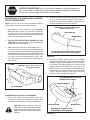
1
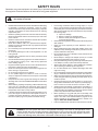
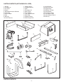
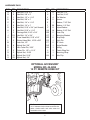
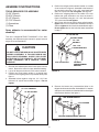
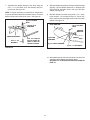
™
owners
manual
Model No.
45-04072
Mow-N-Vac
CAUTION:
Read Rules for
Safe Operation
and Instructions
Carefully
• Safety
• Assembly
• Operating
• Maintenance
• Repair Parts
the fastest way to purchase parts www.speedepart.com
PRINTED IN USA
FORM NO. 40562 (09/04/08)
SAFETY RULES
Remember, any power equipment can cause injury if operated improperly or if the user does not understand how to operate
the equipment. Exercise caution at all times when using power equipment.
Look for this symbol to point out important safety precautions. It means — Attention!! Become alert!!
Your safety is involved.
•
•
•
•
•
•
•
•
•
•
•
•
•
•
•
Read and follow all instructions in this manual before attempting
to assemble or operate this equipment. Failure to comply
with these instructions may result in personal injury. Keep this
manual in a safe place for future reference and for ordering
replacement parts.
Read this operating and service instruction manual carefully.
Be thoroughly familiar with the controls and proper use of this
power vacuum.
Read the vehicle owners manual and vehicle safe operation
rules before using this equipment.
Never allow children under 16 to operate this Vac System.
Children 16 years and older should only operate under close
parental supervision.
Do not allow anyone to operate this equipment without proper
instructions.
Do not allow passengers to ride on this equipment or on the
towing vehicle.
Keep the area of operation clear of others, particularly small
children and pets.
Check fuel before starting engine. Do not fill fuel tank indoors,
or while engine is running or hot. Wipe off any spilled fuel
before starting engine.
Engine and muffler get hot. Do not touch! To avoid fire hazard,
keep clean of debris and other accumulations.
Never store Vac System with fuel in tank. Allow engine to cool
before storing in any enclosure.
Do not change engine governor settings.
Do not operate engine if air cleaner or cover is removed,
except for adjustment. Removal of these parts could create
a fire hazard.
Keep hands, feet, face, long hair and clothing out of inlet and
discharge area. There are ROTATING BLADES inside these
openings.
Before cleaning, repairing or inspecting, make certain all moving
parts come to a complete stop. Disconnect spark plug wire
and keep wire away from plug to prevent accidental starting.
Keep throttle control lever in stop position.
If the Vac System should become blocked with debris at any
point, shut engine off and wait until the impeller comes to a
complete stop before attempting to remove the obstruction.
Disconnect spark plug wire to prevent accidental starting.
•
If the cutting mechanism strikes a foreign object, or if your
Mow-n-vac should start to vibrate abnormally, stop the engine
immediately, disconnect the spark plug wire and move the wire
away from the spark plug. Allow the machine to stop and take
the following steps.
a. Inspect for damage.
b. Repair or replace any damaged parts.
c. Check for loose parts and tighten to assure
continued safe operation.
• Check all bolts for tightness at frequent intervals to help insure
safe operation.
• Check cart cover frequently for wear. Replace if worn or
damaged.
• Never operate Mow-N-Vac unless deck adapter, hose, hose
adapter (nozzle), discharge chute (elbow), and cart cover are
properly attached in their place.
• Do not remove cart cover or attempt to empty contents of cart
while engine is running.
• Never attempt to change hose adapter (nozzle) or to install
remote hose attachment when engine is running.
• Keep all shields and guards (e.g. discharge chute (elbow) and
hose adapter (nozzle) in place and securely attached.
• Always wear safety glasses or other suitable eye protection
when operating or maintaining this equipment.
• Do not stand behind cart in exhaust discharge area while
engine is running.
• Do not operate this equipment while intoxicated or while taking
drugs or medication that impairs the senses and reactions.
• When using this equipment, start with the vehicle transmission
in first (low) gear and then gradually increase speed only as
conditions permit.
• Operate this equipment at reduced speed on rough terrain,
along creeks and ditches and on slopes to prevent tipping or
loss of control. Do not drive too close to a creek or ditch.
• Vehicle braking and stability are affected by the addition of
this equipment. Do not fill the Mow-N-Vac to its full capacity
without checking the capability of the towing vehicle to safely
pull and stop with the Mow-N-Vac attached.
• Before operating on any grade (hill) refer to the safety rules
in the vehicle owner’s manual concerning safe operation on
slopes. Also refer to the SLOPE GUIDE on page 25 of this
owner’s manual. Do not operate on slopes in excess of 10
degrees. STAY OFF STEEP SLOPES.
• Follow the maintenance instructions outlined in this manual.
DANGER: This Vac System was built to be operated according to the rules for safe operation in this
manual. As with any type of power equipment, carelessness or error on the part of the operator can result
in serious injury. This unit is capable of amputating fingers and hands and throwing objects. Failure to
observe the following safety instructions could result in serious injury or death.
2
CARTON CONTENTS (NOT SHOWN FULL SIZE)
1. Tailgate
2. Cart Body (2)
3. Cart Cover
4. Engine
5. Tailgate Reinforcement Bracket
6. Front Panel
7. Mower Adapter
8. Hose
9. Wheel (2)
10. Hose Clamp (2)
11. Wheel Support
12. Tailgate Guide (2)
13. Axle
14. Tarp Strap, 25"
15. Rear Tongue
16. Front Tongue
17. Latch Stand Bracket
18. Hitch Plate
19. Adapter Bracket
20. Hose Hanger Rod
1
21. Hitch Bracket
22. Latch Lock Lever
23. Tailgate Rope
24. Deflector w/ Elbow
25. Hose Adapter
26. Top Support Angle
27. Front Support Tube
28. Lower Support Rod (3)
29. Brace (2)
2
3
4
6
5
7
11
8
10
9
12
16
15
14
13
19
18
17
20
21
22
24
25
23
26
28
29
CARTON CONTENTS
3
27
A
E
D
C
H
G
F
J
I
M
L
P
N
R
O
K
V
W
U
Q
X
B
S
Y
T
Z
AA
NOT SHOWN FULL SIZE
BB
CC
DD
FF
II
EE
HH
GG
HARDWARE PACK
4
JJ
KK
HARDWARE PACK
REF. QTY. DESCRIPTION
A
1
Hex Bolt, 5/16" x 4"
B
5
Hex Bolt, 3/8" x 3"
C
1
Hex Bolt, 1/2" x 1-1/4"
D
4
Hex Bolt, 3/8" x 1"
E
6
Hex Bolt, 1/4" x 1-1/4"
F
6
Hex Bolt, 1/4" x 1"
G
4
Hex Bolt, 5/16" x 3/4" (self thread)
H
2
Hex Bolt, 5/16" x 1-1/4"
I
2
Carriage Bolt, 5/16" x 3/4"
J
23 Hex Bolt, 1/4" x 3/4"
K
12 Truss Head Bolt, 5/16" x 3/4"
L
2
Slotted Head Bolt, 10-32 x 5/8"
M
1
Lock Nut, 1/2"
N
9
Nylock Nut, 3/8"
O
1
Hair Cotter Pin, 3/32"
P
2
Cotter Pin, 1/8" x 1-1/4"
Q
2
Nylock Nut, 10-32
R
15 Nylock Nut, 5/16"
S
33 Nylock Nut, 1/4"
REF. QTY. DESCRIPTION
T
8
Lock Nut, 1/4"
U
1
Lock Nut, 5/16"
V
4
Flat Washer
W
2
Spacer
X
1
Washer, 7/16" Std.
Y
20 Washer, 1/4" Std.
Z
9
Nylon Washer
AA
14 Washer, 5/16" Std.
BB
2
Hose Clip
CC
1
Mounting Bracket
DD
2
Tarp Strap
EE
1
Hitch Pin
FF
2
"S" Hook
GG
1
Angle Bracket
HH
1
Spring
II
3
Plastic Wing Nut
JJ
1
Mounting Strap
KK
2
Axle Clip
OPTIONAL ACCESSORY
MODEL NO. 45-0253
12 FT. REMOTE HOSE KIT
The Remote Hose Kit, Model 45-0253, provides
12' x 5" diameter hose to clean around shrubs,
patios, window wells and other areas not
accessible to the tractor.
5
ASSEMBLY INSTRUCTIONS
5. Position the tailgate reinforcement bracket on outside
of cart as shown in figure 2. Assemble to the bottom of
the cart body using four 5/16" x 3/4" truss head bolts
and 5/16" nylock nuts. Do not tighten. See figure 2.
6. Position the tailgate guides on the inside of the cart
bodies with guide channels to the front as shown in
figure 2. Assemble using four 1/4" x 3/4" hex bolts and
1/4" nylock nuts. Do not tighten.
7. At this time, with the cart body halves pulled together,
tighten the four truss head bolts assembled in step 5
and then tighten the four hex bolts assembled in step 6.
Do not tighten the two hex bolts that were assembled
in step 4.
TOOLS REQUIRED FOR ASSEMBLY
(2)3/4" Wrench
(2)9/16" Wrench
(2)1/2" Wrench
(2)7/16" Wrench
(1)Screwdriver
(1) Pliers
Spray adhesive is recommended for easier
assembly!
1/4" NYLOCK NUT
This unit is shipped WITHOUT GASOLINE or OIL. After
assembly, see separate engine manual for proper fuel and
engine oil recommendations.
TAILGATE GUIDE
1/4" x 3/4"
HEX BOLT
5/16" x 3/4"
TRUSS HEAD BOLT
CAUTION
DO NOT LEAVE THE MOW-N-VAC UNATTENDED
DURING ASSEMBLY. A FALLING MOW-N-VAC
CAN CAUSE PERSONAL INJURY! PAY CLOSE
ATTENTION TO THE STABILITY OF THE MOWN-VAC. ASSEMBLE ON A SMOOTH, LEVEL
SURFACE.
5/16" NYLOCK NUT
1. Remove the hardware pack and all loose parts from the
carton. Be sure the carton is empty before discarding.
2. Lay out all the parts as shown in the carton contents.
3. Position cart body halves upright on a smooth level
surface such as a garage floor or a paved driveway. See
figure 1.
4. Assemble halves together using two 1/4" x 3/4" hex
bolts and 1/4" nylock nuts as shown in figure 1. Do not
tighten.
TAILGATE
REINFORCEMENT
BRACKET
FIGURE 2
8. Remove the bottom two pre-assembled bolts in the
tailgate reinforcement bracket. Assemble a 5/16" washer
and spacer onto the bolt and reassemble it to the tailgate
reinforcement bracket. See figure 3.
1/4" x 3/4" HEX BOLT
1/4" NYLOCK NUT
PRE-ASSEMBLED BOLT
SPACER
5/16" WASHER
TAILGATE REINFORCEMENT BRACKET
FIGURE 3
FIGURE 1
6
9. Assemble the front panel over the opposite end of the
cart using four 1/4" x 3/4" hex bolts and 1/4" nylock
nuts as shown in figure 4. Leave two holes open in the
bottom of the panel as shown in figure 4. With the cart
body halves pulled together, tighten the two bolts in the
bottom of the front panel, then tighten the bolt in each
side.
At this time tighten the two bolts on the bottom of the
cart which were assembled in step 4.
LEAVE HOLES OPEN FOR
LATCH STAND BRACKET
11. Turn the latch stand bracket so that the aligning tab is
at the rear (bottom) of the bracket. Assemble the latch
stand bracket to the cart using four 1/4" x 3/4" hex bolts
and 1/4" nylock nuts. Tighten. See figure 6.
LATCH STAND BRACKET
1/4" x 3/4"
HEX BOLT
1/4" x 3/4"
HEX BOLT
1/4" NYLOCK NUT
ALIGNING TAB
AT BOTTOM
1/4" HEX NUT
FIGURE 6
1/4" NYLOCK NUT
1/4" x 3/4"
HEX BOLT
FIGURE 4
12. Assemble two 1/4" x 3/4" hex bolts and 1/4" nylock
nuts to the two rear corners of the cart. Tighten. See
figure 7.
10. Assemble the wheel support to the cart using eight
5/16" x 3/4" truss head bolts and 5/16" nylock nuts as
shown in figure 5. Heads of bolts go on the inside of
cart. Tighten.
5/16" x 3/4"
TRUSS HEAD BOLT
WHEEL
SUPPORT
5/16"
NYLOCK
NUT
1/4" x 3/4"
HEX BOLT
FIGURE 5
FIGURE 7
7
1/4" NYLOCK
NUT
IMPORTANT: Make sure drawbar tongue is securely
locked to the latch stand bracket by the latch lock lever.
13. Insert the latch lock lever into the rear tongue as shown
in figure 8A. Secure it in place using the 5/16" x 4" hex
bolt and 5/16" nylock nut.
14. Attach the spring to the hole in the rear tongue and
the lower hole in the latch lock lever as shown in figure
8B.
17. Assemble a flat washer, a wheel with the valve stem
facing out, another flat washer and an axle clip onto
the axle as shown in figure 10. Secure the wheel on
the axle with a cotter pin, spreading the ends. Repeat
on other end of axle.
A
LATCH
LOCK
LEVER
5/16" LOCK NUT
WHEEL
AXLE
FLAT
WASHER
AXLE
CLIP
5/16" x 4"
HEX BOLT
FLAT
WASHER
B
COTTER PIN
SPRING
FIGURE 10
FIGURE 8
18. Assemble the hitch bracket to the front tongue using two
3/8" x 1" hex bolts and 3/8" nylock nuts. See figure 11.
TONGUE
(FRONT)
15. To prevent accidental tipping during the following
assembly procedures, lower the cart to rest upside down
on its top flanges, so that the wheel support is facing
up. See figure 9.
16. Lay the drawbar tongue onto the Wheel Support and
the Latch Stand Bracket. Assemble the axle through
the wheel support and the tongue. See figure 9.
3/8" x 1"
HEX BOLT
HITCH
BRACKET
AXLE
3/8" NYLOCK
NUT
REAR
TONGUE
FIGURE 11
LATCH STAND
BRACKET
FIGURE 9
8
19. Flip the cart over so that it rests on its wheels.
20. Assemble the front tongue on top of the rear tongue
using three 3/8" x 3" hex bolts and 3/8" hex lock nuts.
See figure 12.
HINT: For easier assembly, support the rear tongue with
a block of wood.
21. Assemble the hitch pin to the hitch bracket and tongue,
securing it with the 1/8" hair cotter pin. See figure 12.
24. Assemble the engine to the tongue using two 3/8" x 3"
hex bolts in the rear holes, two 3/8" x 1" hex bolts in the
front holes and four 3/8" nylock nuts. See figure 14.
HINT: Use caution when assembling engine to tongue. Have
another person assist you if you are having difficulty.
HINT: For easier assembly, support the tongue with a block
of wood.
HITCH PIN
3/8" x 3"
HEX BOLT
TONGUE
(FRONT)
3/8" x 1"
HEX BOLT
3/8" HEX
LOCK NUT
BLOCK
3/8" x 3"
HEX BOLT
1/8" HAIR
COTTER PIN
3/8" NYLOCK NUT
FIGURE 12
FIGURE 14
22. Attach the plastic elbow to the top of the engine housing
using four 5/16" x 3/4" hex bolts (self tapping) and nylon
washers. See figure 13.
HINT: Push in on hex bolts as you tighten to form threads.
23. Connect the hose adapter to the engine housing by
fastening three wing nuts to the pre-assembled bolts
in the engine housing. See figure 13.
25. Place the hose hanger rod down into the hose hanger
bracket on the impeller housing assembly. See figure
15.
HOSE HANGER ROD
NYLON WASHER
5/16" X 3/4"
HEX BOLT
(SELF TAP)
WING NUT
FIGURE 13
FIGURE 15
9
26. Place a hose clamp onto the end of the hose. Push the
hose onto the hose adapter (nozzle). Tighten the hose
clamp onto the hose and hose adapter. Do not collapse
the hose adapter when tightening the clamp. See
figure 16.
27. The remaining hose clamp will be used later to fasten
the hose to the deck adapter.
29. Assemble the hitch plate to the tractor hitch if:
a. Your tractor has a square (straight) hitch frame, to help prevent binding.
b. Your tractor has a lightweight hitch frame that needs reinforcement for towing.
Use a 1/2" x 1-1/2" hex bolt, a 7/16" flat washer and a
1/2" lock nut. See figure 18.
1/2" x 1-1/2"
HEX BOLT
TRACTOR HITCH
FRAME (SQUARE)
HOSE ADAPTER
(NOZZLE)
ATTACH
MOW-N-VAC
HERE
CLAMP
7/16" FLAT WASHER
HOSE
1/2" LOCK NUT
TRACTOR HITCH
FRAME (TAPERED)
FIGURE 18
FIGURE 16
28. Loop the 25" tarp strap under the hose. Fasten the hooks
to the hose hanger rod. See figure 17.
HOSE HANGER ROD
25" TARP
STRAP
FIGURE 17
10
HITCH
PLATE
ASSEMBLING CART COVER
3. Slide the last lower support rod through outer edge of
the cart cover. The bend in the rod must face in the
direction shown in figure 21.
1. Slide the front support tube through the double loops
located near the front of the cart cover. See figure 19.
CART COVER
DOUBLE LOOPS
SUPPORT ROD
BEND
FRONT
SUPPORT
TUBE
CART COVER
FIGURE 21
FIGURE 19
PERFORM STEPS 4-6 IF YOU ARE USING SPRAY
ADHESIVE (RECOMMENDED). IF YOU ARE NOT USING
SPRAY ADHESIVE, SKIP TO STEP 7 ON PAGE 12.
4. Apply spray adhesive to the side of the top support angle
shown in grey. Follow directions on spray adhesive for
proper application. See figure 22.
5. Once the spray adhesive is tacky to touch, place top
support angle inside of cart cover and fold the edges of
the cover onto side of support angle with spray adhesive.
See figure 22.
6. Wait until adhesive dries, securing support angle in
place, before continuing to step 7.
2. Slide two of the lower support rods through the center
loops located in the top of the cart cover as shown in
figure 20.
CENTER LOOP
TOP SUPPORT
ANGLE
CENTER LOOP
SUPPORT
RODS
CART
BAG
CART COVER
SPRAY
ADHESIVE
FOLD EDGES
FIGURE 20
FIGURE 22
11
7. Secure front support tube to top angle support using
two 1/4" x 1-1/4" hex bolts and 1/4" lock nuts. DO NOT
TIGHTEN YET. See figure 23.
9. Attach the second lower support rod to the outside and
the third lower support rod to the inside of the top angle
support using two 1/4" x 3/4" hex bolts and 1/4" lock
nuts. DO NOT TIGHTEN YET. See figure 25.
NOTE: Cart bag not shown for clarity.
NOTE: Cart bag not shown for clarity.
2ND ROD
1/4" LOCK
NUT
1/4" LOCK NUT
1/4" x 1-1/4" HEX BOLT
FIGURE 23
1/4" x 3/4"
HEX BOLT
3RD ROD
FIGURE 25
10. Attach the braces to the front support tube using two
1/4" x 1-1/4" hex bolts and 1/4" lock nuts. DO NOT
TIGHTEN YET. See figure 26.
8. Attach the lower support rod closest to front support tube
to the outside of the top angle support using two 1/4"
x 3/4" hex bolts and 1/4" lock nuts. DO NOT TIGHTEN
YET. See figure 24.
NOTE: Cart bag not shown for clarity.
NOTE: Cart bag not shown for clarity.
1/4" LOCK
NUT
1/4" x 1-1/4"
HEX BOLT
1/4" LOCK NUT
1/4" x 3/4" HEX BOLT
FIGURE 24
FIGURE 26
12
13. Slide each end of the rope through the holes in the
tailgate shown in figure 28.
14. Tie a knot in the end of each side of the rope to secure
the rope in place. Keep knot loose. See figure 28.
HINT: Knot may need to be moved up or down in rope to
secure tailgate. See step 18 for more information.
15. Slide tailgate into tailgate guides.
16. Attach clips to 3rd lower support rod and fasten them
to the tailgate using two #10 x 5/8" slotted head bolts
and #10 nuts. See figure 28.
17. TIGHTEN all bolts assembled in steps 7 through 12.
18. Secure tailgate rope around the bolts shown in figure
28. If rope does not keep tailgate held down or rope
is too short to secure around bolts, move the knot up
the end of the rope to loosen or down to tighten. Once
knot is in desired location, tighten the knot to secure it
in place.
While performing the assembly operations
in step 11, make sure the cart bag is between
the top angle support and the cart.
11. Place the top angle support and cart bag ontop of the
cart as shown in figure 27. Then, using a screwdriver
or other sharp object, poke holes through the cart bag
for the bolts that will be assembled in step 12.
12. Attach the top angle support and braces to the cart using
seven 1/4" x 3/4" hex bolts, fourteen 5/16" washers (one
placed on each side) and seven 1/4" nylock nuts. DO
NOT TIGHTEN YET. See figure 27.
NOTE: Cart bag not shown for clarity.
NOTE: Cart bag not shown for clarity.
1/4" x 1"
HEX BOLT
1/4" x 3/4"
HEX BOLT
#10-32 x 5/8"
TRUSS BOLT
1/4"
WASHER
CLIP
KNOT
#10-32
NYLOCK
NUT
ROPE
1/4"
WASHER
SECURE
ROPE
1/4"
NYLOCK
NUT
FIGURE 28
FIGURE 27
13
STOP
BEFORE PROCEEDING, look in the fold-out sheets to find the template for
your mower deck. If written instructions are printed on the template, follow those
instructions instead of the instructions in this manual.
ASSEMBLING THE #62468 DECK ADAPTER
TO THE MOWER DECK
5. Position the adapter over the deck opening, and check
for fit of cutout as shown in figure 30. Trim cutout, if
necessary, to allow tilting of adapter, keeping the fit as
close as possible for best vacuum suction.
NOTE: Not all of the parts in the deck adapter hardware
package will be used for any one particular fit up.
NOTE: Make sure adapter clears gauge
wheels on mower deck
1. Identify and cut out the template for your brand and
size mower deck. If there is no template included for
your deck size, you can make your own template by
marking around a piece of cardboard held against the
edge of the deck's discharge opening.
DECK ADAPTER
MOWER DECK
2. FOLLOW THE INSTRUCTIONS PRINTED ON THE
TEMPLATE. If there are no instructions, use the following
instructions as a general guide.
3. Tape the template to the face of the adapter, about
1/2" from front and 1/4" down from top for deeper decks.
For shallow decks, position template low enough that
adapter will not extend below bottom of deck. Mark outline
of template on face of adapter using white crayon, nail
or scriber. Drill a starting hole inside the outline, then
use a saber saw or key hole saw to cut out the opening. See figure 29.
1/4" DOWN
Curl on deck may be located outside of adapter
or inside depending on deck opening design
FIGURE 30
6. Holding the adapter bracket and the deck adapter
together, position the deck adapter on the mower deck.
Keeping the edge of deck adapter as close as possible
to the offset in the adapter bracket, see if the slot in the
adapter bracket can be aligned with one or two of the
deflector holes in your mower deck’s discharge opening.
If the bracket can not be located correctly using existing
holes, it will be necessary to drill one or two 5/16"
diameter holes in the deck. See figure 31.
IMPORTANT: Keep cut-off as close to
the top edge as possible.
Use existing holes or drill 5/16"
diameter hole or holes.
ADAPTER BRACKET
1/2" FROM FRONT
FIGURE 29
PERFORM THIS STEP ONLY IF NECESSARY.
4. Remove the mower discharge deflector from your
mower deck if necessary to attach deck adapter. Save
the deflector and hardware for remounting deflector.
DECK ADAPTER
CAUTION: Mower deflector must be
replaced when Vac System deck adapter
is removed. Do Not operate mower unless
adapter or deflector is in place and properly
mounted.
MOWER DECK
Keep edge of adapter as close
as possible to offset in bracket
FIGURE 31
14
7. Assemble the adapter bracket to the deck using two
5/16" x 1-1/4" hex bolts, 5/16" flat washers and 5/16"
nylock nuts. See figure 32.
8. With deck adapter positioned correctly over the discharge
opening, use the adapter bracket as a template and
drill three 9/32" diameter holes in the top of the deck
adapter. See figure 33.
NOTE: It may be necessary to use extra 5/16" flat washers
to shim under the bracket next to the deck surface. Ten extra
washers have been furnished as shims. See figure 32.
9. Bolt deck adapter to bracket using three 1/4" x 1" bolts,
nylon washers, 1/4" flat washers and 1/4" nylock nuts. Nylon washers should be against the inside of the deck
adapter. See figure 33.
(2) 5/16" NYLOCK
NUTS
DECK ADAPTER
(2) 5/16" FLAT
WASHERS
(3) 1/4" NYLOCK
NUTS
ADAPTER
BRACKET
ADAPTER BRACKET
5/16" x 1-1/4"
HEX BOLT
(3) NYLON
WASHERS
5/16" flat washers
used as needed for
shims to adjust for
variations in decks.
MOWER DEC
K
(3) 1/4" STEEL WASHERS
(3) 1/4" x 1" HEX BOLTS
FIGURE 32
FIGURE 33
10. Assemble end of hose and a hose clamp over the round
opening of deck adapter and tighten clamp.
GO DIRECTLY TO OPERATION INSTRUCTIONS ON
PAGE 16.
15
OPERATION
KNOW YOUR VAC SYSTEM
Read this owner's manual and safety rules before operating your Vac System.
Compare the illustration below with your Vac System to familiarize yourself with the various controls and their locations.
BOOT
CHOKE
CONTROL
THROTTLE
CONTROL
LATCH LOCK LEVER
LATCH LOCK LEVER Locks the cart bed down to the tongue.
Releases to allow cart to be tipped back for dumping.
THROTTLE CONTROL Controls speed of engine.
CHOKE CONTROL Adjust to allow cold starting.
BOOT Connects the plastic elbow to the fabric top, directing
discharged material into the cart.
CAUTION: Alcohol blended fuels (called gasohol or using ethanol
BEFORE STARTING
or methanol) can attract moisture which leads to separation and
formation of acids during storage. Acidic gas can damage the fuel
system of an engine while in storage.
•
Your Vac System engine is shipped without oil or gasoline.
Service the engine with oil and gas as instructed in the
separate engine manual.
Inspect the Vac System to make sure all covers (rear
door, vinyl boot, elbow, hose adapter, hose and deck
adapter are properly attached.
Check tires for proper inflation (printed on tire).
To avoid engine problems, the fuel system should be emptied
before storage for 30 days or longer. Drain the gas tank, start the
engine and let it run until the fuel lines and carburetor are empty.
Use fresh fuel next season. See
STORAGE Instructions for additional information.
•
Never use engine or carburetor cleaner products in the fuel tank
or permanent damage may occur.
HOW TO STOP YOUR VAC SYSTEM
•
•
WARNING: Never fill fuel tank indoors, with
the engine running, or while the engine is
hot. Do not smoke while filling tank.
•
To stop engine, move the throttle control lever to the
OFF position.
Disconnect spark plug wire from plug to prevent
accidental starting while equipment is unattended or
is being worked on.
CAUTION: The muffler and adjacent areas
are hot!
16
HOW TO START YOUR VAC SYSTEM
TO EMPTY THE CART
• Shut off the tractor engine and set the brake.
• Shut off the Vac engine.
• Loosen the draw string and pull the boot back from the
elbow.
• Remove the tailgate and fold up bag as shown below.
• Use the rope from the tailgate to secure bag in upright
position. Refer to illustration below.
• Release the latch lock lever on the tongue and tip the
cart back.
• Using a rake or suitable tool, pull grass clippings and/or
leaves out of the cart.
• After the cart is emptied, tip it forward and secure it
to the tongue with the latch lock lever. Fold down bag
and install the tailgate. Secure tailgate in place with the
rope.
WARNING: Never start or run the engine
without all covers being properly attached to
the blower housing and cart.
•
•
•
•
•
•
•
Check oil and gas in Vac engine.
Attach spark plug wire to spark plug.
Move choke lever on engine to CHOKE position.
(A warm engine may not require choking.)
Move throttle control lever on engine to FAST
position.
Grasp starter handle and pull rope out slowly until engine
reaches start of compression cycle (rope will pull slightly
harder at this point). Let the rope rewind slowly.
Pull rope with a rapid, continuous, full arm stroke. Keep
a firm grip on starter handle. Let rope rewind slowly. Do
not let starter handle snap back against starter.
Repeat instructions in two preceding paragraphs until
engine fires. When engine starts, move choke control
gradually to RUN position.
CAUTION: To avoid possible injury, be sure
that no one is near the cart before releasing
the latch lock lever.
TO USE THE CART WITHOUT THE VAC SYSTEM
• Remove bolts holding frame to cart and store bag and
frame in a safe place.
• Keep removed bolts, washers and nuts in a safe place
with bag.
• Remove and store the four bolts and nuts which fasten
the engine base to the tongue.
• Slide the engine off the tongue and store in a safe
storage area.
HOW TO USE YOUR VAC SYSTEM
CAUTION: Vehicle braking and stability may
be affected with the addition of an accessory
or an attachment. Be aware of changing
conditions on slopes.
•
Inspect the Vac to make sure the cover, rear door, boot,
elbow, hose adapter (nozzle), hose and deck adapter
are properly attached.
• Check tires for proper inflation (listed on tire).
• Check for oil and gas in Vac engine.
• Begin operation at low speed, adjusting forward speed to
match grass height and/or moisture condition to prevent
clogging.
• Do not attempt to vacuum up any material other than
vegetation found in a normal yard, such as light branches,
leaves, twigs, etc.
CAUTION: The muffler and adjacent areas
are hot!
ROPE
WARNING: Should your Vac System become
clogged, shut off tractor and Vac engines.
Before attempting to unclog, remove wire from
spark plug to prevent accidental starting.
FIGURE 34
17
MAINTENANCE
CUSTOMER RESPONSIBILITIES
•
Read and follow the maintenance schedule and the maintenance procedures listed in this section.
MAINTENANCE SCHEDULE
Fill in dates as you
complete regular service.
se e
e
n
h u h us aso orag
c
t
a
e
c
s
e e ea y s e
for ter ver efor
E
Be Af
B
Service Dates
Check for loose fasteners X
Check cover X
Check tire pressure X
Check engine oil level X
Lubricate
X
Clean
X
X
Maintain engine per instructions below and in engine manual.
BEFORE EACH USE
WARNING: Always stop engine and
disconnect spark plug wire before cleaning,
lubricating or before performing any repairs
or maintenance.
CHECK FOR LOOSE FASTENERS
• Make a thorough visual check of the Vac System for any
bolts and nuts which may have loosened. Retighten any
loose bolts and nuts.
ENGINE MAINTENANCE
CHECK COVER
• Check the cover, especially the front boot and the rear
flap for wear. Replace cover if worn or damaged.
Only use high quality detergent oil rated with API service
classification SF or SG. Select the oil's SAE viscosity grade
according to your expected operating temperature. SAE 30
grade oil is recommended for warm weather use. For cold
weather use refer to the engine manufacturer's Operating
and Maintenance Manual.
CHECK TIRE PRESSURE
• Check tire pressure regularly. Recommended tire
pressure is printed on tire.
•
CHECK ENGINE OIL LEVEL
• Check oil level before each use. Maintain engine oil as
instructed in the separate engine manual.
•
LUBRICATION
•
•
At the beginning of each season, lubricate the latch,
latch pivot bolt, and the axle where the hitch tongue
pivots, with a light machine oil.
At least once a season, grease or oil the wheel bearings.
Use automotive wheel bearing type grease or 20 weight
oil.
•
Check oil level before each use. Maintain engine oil as
instructed in the separate engine manual.
Service air cleaner every 25 hours under normal
conditions. Clean every few hours under extremely
dusty conditions. Poor engine performance and flooding
usually indicates that the air cleaner should be serviced.
To service the air cleaner, refer to the separate engine
manual.
The spark plug should be cleaned and the gap reset
once a season. Spark plug replacement at the start of
each season is recommended. Check the engine manual
for correct plug type and gap specifications.
CLEANING
•
•
18
Make sure the cart and top are cleaned after each use.
Grass clippings and leaves left in the cart will mildew
and cause damage if not cleaned out.
Clean the engine regularly with a cloth or brush. Keep
the cooling fins on the engine housing clean to permit
proper air circulation which is essential to engine
performance and life. Be sure to remove all dirt and
debris from muffler area.
STORAGE
•
•
•
•
Clean the engine and the entire unit thoroughly.
Refer to engine manual for correct engine storage
instructions.
If storing in an unventilated or metal storage shed, coat
metal parts with light oil or silicone to prevent rust.
Store unit in a clean, dry area.
It is important to prevent gum deposits from forming in
essential fuel system parts such as the carburetor, fuel filter,
fuel hose or tank during storage. Also, alcohol blended fuels
(called gasohol or using ethanol or methanol) can attract
moisture which leads to separation and formation of acids
during storage. Acidic gas can damage the fuel system of
an engine while in storage.
To avoid engine problems, the fuel system should be emptied
before storage of 30 days or longer. Follow the instructions
in the engine’s Operating & Maintenance Manual.
TROUBLESHOOTING
PROBLEM
POSSIBLE CAUSE(S)
CORRECTIVE ACTION
Engine fails to start
1. Spark plug wire disconnected.
2. Safety switch not contacted.
3. Fuel tank empty, or stale fuel.
4. Fuel shut-off valve closed
(if so equipped).
5. Faulty spark plug.
1. Connect wire to spark plug.
2. Correctly install hose adapter nozzle.
3. Fill tank with clean, fresh fuel.
4. Open fuel shut-off valve.
5. Clean, adjust gap or replace.
Loss of power;
1. Spark plug wire loose
operation erratic.
2. Unit running on CHOKE.
3. Blocked fuel line or stale fuel.
4. Water or dirt in fuel system.
5. Carburetor out of adjustment.
6. Dirty air cleaner.
1. Connect and tighten spark plug wire.
2. Move choke lever to OFF position.
3. Clean fuel line; fill tank with clean
fresh gasoline.
4. Disconnect fuel line at carburetor to drain
fuel tank. Refill with fresh fuel.
5. Adjust carburetor.*
6. Service air cleaner.*
Engine overheats
1. Adjust carburetor.*
1. Carburetor not adjusted
properly.
2. Engine oil level low.
2. Fill crankcase with proper oil.
Too much vibration
Loose parts or damaged
impeller.
1. Stop engine immediately and disconnect
spark plug wire. Tighten all bolts and nuts.
Make all necessary repairs. If vibration
continues, have unit serviced by an
authorized service dealer.
Unit does not
1. Discharge chute (elbow)
discharge
clogged.
2. Foreign object lodged in
impeller.
3. Vac Cart is full.
1. Stop engine immediately and disconnect
spark plug wire. Clean inside of housing
and discharge chute (elbow).
2. Stop engine immediately and disconnect
spark plug wire. Remove lodged object.
3. Empty cart.
*Refer to the engine manual packed with your unit.
NOTE: For repairs beyond the minor adjustments listed above, please contact your nearest authorized service dealer.
19
CART REPAIR PARTS
FOR 45-04072 Mow-N-Vac
3
4
15
16
5
15
1
17
15
17
16
16
29
A
18
2
15
28
1
A
16
9
27
6
7
16
31
19
10
18
25
21
25
22
13
20
19
11
12
30
6
26
8
14
23
23
23
20
24
REPAIR PARTS LIST FOR 45-04072 Mow-N-Vac
REF.
NO.
PART
NO.
QTY. DESCRIPTION
REF.
NO.
PART
NO.
1
23912
2
2
24906
3
62458
4
QTY. DESCRIPTION
Cart Body
17
43814
12
Truss Head Bolt, 5/16-18 x 3/4"
1
Front Panel
18
47810
13
Nylock Nut, 5/16-16
1
Tailgate Reinforcement Bracket
19
43009
4
Washer
24907
1
Tailgate
20
43010
2
Cotter Pin
5
23548
2
Tailgate Guide
21
23353
1
Hitch Pin
6
24896
1
Axle
22
43001
2
Hex Bolt, 3/8-16 x 1"
7
44456
2
Wheel
23
HA21362
5
Nylock Nut, 3/8-16
8
65426
1
Rear Tongue
24
43343
1
Hair Cotter Pin, 3/32"
9
25996
1
Wheel Support
25
43574
3
Hex Bolt, 3/8-16 x 3"
10
24497
1
Latch Stand Bracket
26
47407
1
Hex Bolt, 5/16-18 x 4"
11
25742
1
Front Tongue
27
49868
1
Rope, 36"
12
23475
1
Hitch Bracket
28
23625
2
Spacer, .38" x .62" x .27"
13
25010
1
Latch Lock Lever
29
43081
2
Washer, 5/16" Std.
14
HA20186
1
Spring
30
43064
1
Lock Nut, 5/16-16
15
43012
16
Hex Bolt, 1/4-20 x 3/4"
31
25912
2
Axle Clip
16
47189
16
Nylock Nut, 1/4-20
the fastest way to purchase parts www.speedepart.com
21
REPAIR PARTS FOR MODEL 45-04072
Mow-N-Vac
6
4
4
2
16
42
18
38
15
37
39
12
3
43
18
18
4
3
18
27
19
19
25
7
25
1
13
42
19
ADAPTER #62468
20
13
25
8
36
27
21
12
25
42
25
32
31
5
12
27
25
8
47
34
8
31 33
13
27
25
13
8
40
34
44
9
11
17
31
27
13
46
45
47
23
28
41
27
25
14
23
26
30
29
12
35
13
22
TO
TRACTOR
REPAIR PARTS FOR MODEL 45-04072
Mow-N-Vac
REF.
NO.
PART NO.
QTY. DESCRIPTION
REF.
NO.
PART NO.
1
25836
1
2
25740
3
QTY. DESCRIPTION
Top Support Angle
25
43088
20
Washer, 1/4" Std.
1
Front Support Tube
26
23540
1
Hitch Plate
25876
2
Brace
27
1543-69
9
Nylon Washer
4
49864
3
Lower Support Rod
28
43351
1
Hex Bolt, 1/2-13 x 1-1/4"
5
43840
2
Hex Bolt, 5/16-18 x 1-1/4"
29
43262
1
Lock Nut, 1/2-13
6
49865
1
Cart Cover
30
43352
1
Flat Washer, 7/16"
7
40996
1
Engine (49 State)
31
43081
12
Washer, 5/16" Std.
40999
1
Engine (California)
32
43830
1
Deck Adapter
8
47810
7
Nylock Nut, 5/16-18
33
23560
1
Deck Adapter Bracket
9
25834
1
Engine Mounting Base
34
43080
2
Carriage Bolt, 5/16" x 3/4"
10
65428
1
Impeller Assembly
35
23825
1
Mounting Strap
11
43791
1
Hose Adapter
36
23826
1
Angle Bracket
12
43661
4
Hex Bolt, 1/4-20 x 1"
37
HA23761
2
Clip
13
47189
17
Nylock Nut, 1/4-20
38
43346
2
Truss Head Bolt, #10-32 x 5/8"
14
43792
1
Hose
39
47171
2
Nylock Nut, #10-32
15
49974
1
Hose Hanger Rod
40
62486
1
Deck Adapter Kit
16
46420
1
Deflector w/ Elbow
41
23827
1
Mounting Bracket
17
712-0421
3
Wing Nut
42
1509-90
6
Hex Bolt, 1/4-20 x 1-1/4"
18
43013
8
Lock Nut, 1/4-20
43
47630
4
Hex Bolt, 5/16-18 x 3/4"
19
43012
9
Hex Bolt, 1/4-20 x 3/4"
20
44850
2
Tarp Strap
44
43001
2
Hex Bolt, 3/8-16 x 1"
21
44849
2
"S" Hook
45
43574
2
Hex Bolt, 3/8-16 x 3"
22
43793
2
Hose Clamp
46
43085
4
Hex Bolt, 5/16-18 x 1-1/2"
23
43790
1
Tarp Strap, 25"
47
HA21362
4
Nylock Nut, 3/8-16
24
24958
1
Hose Hanger Bracket
40562
1
Owners Manual
(Thread Forming)
23
REPAIR PARTS FOR MODEL 45-04072 Mow-N-Vac
IMPELLER HOUSING ASSEMBLY
2
11
2
18
2
10
5
4
9
52
9
16
3
24
17
78
4
10
8
24
20
6
15
12
19
4
21
22
15
13
16
14
16
1
23
REF.
NO.
PART
NO.
QTY. DESCRIPTION
REF.
NO.
PART
NO.
1
629-0241a
1
2
24634
3
4
Harness, Wire
13
725-3166
1
Snap Mount Switch
1
Housing Assembly, Inner
14
726-0272
1
Clamp
24633
1
Housing Assembly, Outer
15
731-1613
1
Switch Cover
43182
10
Hex Bolt, 5/16-18 x 3/4"
16
24958
1
Hose Hanger Bracket
5
40320
4
Hex Bolt, 5/16-24 x 1-1/4"
17
48848
3
Nylock Jam Nut, 5/16-18
6
710-1268
2
Screw, Self Tap #10-16 x 3/8"
18
43081
4
Washer, 5/16" Std.
7
43063
3
Hex Bolt, 5/16-18 x 1"
19
736-0247
1
Washer, 13/32" x 1-1/4"
8
712-0421
3
Wingnut
20
65428
1
Impeller Assembly
9
47810
12
Nylock Nut, 5/16-18
21
44377
1
Hex Bolt, 3/8-24 x 1"
10
43086
4
Lock Washer, 5/16"
22
43003
1
Lockwasher, 3/8"
11
23727
4
Spacer
23
49869
1
Wire Mag. Ground
12
725-1700
1
Switch Cover
24
23477
1
Key, 1/4" Sq. 2" Long
24
QTY. DESCRIPTION
(Keep this sheet in a safe place for future reference.)
Use this guide to determine if a slope is safe for the operation of your tractor and Vac. Refer also
to the instructions in your vehicle owners manual.
SLOPE GUIDE
SIGHT AND HOLD THIS LEVEL WITH A VERTICAL TREE
A POWER POLE
A CORNER OF A BUILDING
OR A FENCE POST
FOLD
A
L
O
NG DO
TTED L
INE
,
R
E
P
RESEN
TING A
1
0
D
E
G
REE S
LOPE
CAUTION: DO NOT OPERATEYOUR TRACTOR AND CART ON A SLOPE
IN EXCESS OF 10 DEGREES. BE SURE OF YOUR TRACTOR'S TOWING
AND BRAKING CAPABILITIES BEFORE OPERATING ON A SLOPE.
AVOID ANY SUDDEN TURNS OR MANEUVERS WHILE ON A SLOPE.
25
NOTES
26
NOTES
27
the fastest way to purchase parts www.speedepart.com
REPAIR PARTS
Agri-Fab, Inc.
809 South Hamilton
Sullivan, IL. 61951
217-728-8388
www.agri-fab.com
This document (or manual) is protected under the U.S. Copyright Laws and the copyright laws of foreign countries,
pursuant to the Universal Copyright Convention and the Berne convention. No part of this document may be reproduced
or transmitted in any form or by any means, electronic or mechanical, including photocopying or recording, or by any
information storage or retrieval system, without the express written permission of Agri-Fab, Inc. Unauthorized uses and/or
reproductions of this manual will subject such unauthorized user to civil and criminal penalties as provided by the United
States Copyright Laws.
© 2006 Agri-Fab, Inc.
28