1
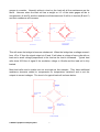
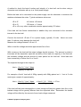
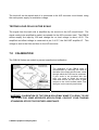
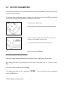
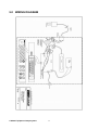
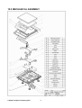
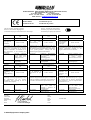
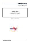
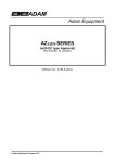
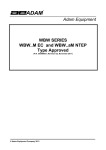
.
Adam Equipment
CBK-M SERIES
Service Manual
Software rev.: 4.07 & above
ADAM EQUIPMENT CO. LTD.
P.N. 9017, Rev. A3, October 2007
© Adam Equipment Company 2007
© Adam Equipment Company 2007
CONTENTS
1.0
INTRODUCTION.......................................................................................................2
2.0
SPECIFICATIONS ....................................................................................................3
3.0
TROUBLESHOOTING ..............................................................................................4
4.0
ERROR CODES .......................................................................................................5
5.0
CBK-M DESCRIPTION .............................................................................................6
6.0
LOAD CELL DAMAGE..............................................................................................6
7.0
CALIBRATION ..........................................................................................................9
7.1
7.2
8.0
8.1
8.2
8.3
8.4
8.5
8.6
8.7
8.8
8.9
SECURITY SEALS ..............................................................................................10
CALIBRATION PROCEDURE .............................................................................10
FACTORY PARAMETERS .....................................................................................11
F1 -CALIBRATION................................................................................................12
F2 -RESOLUTION ................................................................................................13
F3 – CAPACITY....................................................................................................13
F4 -INITIAL ZERO RANGE ...................................................................................13
F5 -RE-ZERO RANGE .........................................................................................14
F6 -SUCCESSIVE TARE......................................................................................14
F7 -A/D COUNT ....................................................................................................15
F8 –ZERO ............................................................................................................15
F9 –LOW VOLTAGE DETECTION .......................................................................16
9.0
WIRING DIAGRAM .................................................................................................17
10.0
MECHANICAL ASSEMBLY ....................................................................................18
*****
© Adam Equipment Company 2007
1
1.0 INTRODUCTION
•
The CBK-M series of scales provide an accurate, fast and versatile general
purpose weighing scales with counting, percent weighing and checkweighing functions.
•
CBK-M scales are kilogram only scales.
•
There are 4 models with capacities up to 30kg.
•
The scales have LEDs to indicate when a weight is below the low limit,
between the limits or above the high limit next to the display. These can
work in conjunction with an audible alarm for check weighing as well as LCD
showing LO, OK and HI.
•
The scales have stainless steel weighing platforms on an ABS base
assembly.
•
All scales are supplied with a RS-232 bi-directional interface and real time
clock (RTC). NOTE: For Approved applications, CBK-M Scales do not come
with the RS-232 interface. However, the scales can be supplied with RS-232
interface if they are not to be used for approved applications.
•
The scales have sealed keypads with colour coded membrane switches and
a large easy to read liquid crystal type display (LCD) supplied with a
backlight.
•
The scales include automatic zero tracking, semi-automatic tare,
accumulation facility that allows the count and weight to be stored and
recalled as an accumulated total.
© Adam Equipment Company 2007
2
2.0 SPECIFICATIONS
CBK 3M
CBK 6M
CBK 15M
CBK 30M
Max
3000 g
6000 g
15000 g
30000 g
d=
1g
2g
5g
10 g
n=
3000
3000
3000
3000
Max
3kg
6kg
15kg
30 kg
d=
0.001kg
0.002kg
0.005kg
0.01 kg
Grams
Kilograms
OTHER SPECIFICATIONS
Units of measure
Interface
Stabilisation Time
Kg, g
RS-232 bi-directional Interface
NOTE: For Approved applications, CBK-M Scales do not come with the RS-232
interface. However, the scales can be supplied with RS-232 interface if they are
not to be used for approved applications.
2 Seconds typical
Operating Temperature
-10°C to 40°C / 14°F to 104°F
Power supply
115/230 VAC Mains, 50/60 Hz
or 9 VDC, 800 mA through an external adapter
Battery
Internal rechargeable battery (~90 hours operation)
Calibration
Not available
Display
6 digits LCD digital display
with capacity tracker and symbol for unit
Scale Housing
ABS Plastic, Stainless Steel platform
Pan Size
225 x 275 mm / 8.9” x 10.8”
Overall Dimensions
(wxdxh)
315 x 355 x 110 mm
12.4” x 14” x 4.3”
Net Weight
4.1 kg / 9 lb
Applications
Weighing Scales
Functions
Weighing, Parts counting, % weighing, Check weighing,
Check counting, Accumulation of weights
Date/Time
Real Time Clock (RTC),
To print date and time information- battery backed.
NOTE: For Approved applications, CBK-M Scales do not come with
the RS-232 interface.
© Adam Equipment Company 2007
3
3.0 TROUBLESHOOTING
PROBLEM
POSSIBLE CAUSE
Display is blank
No turn on test
Power Switch faulty or not connected
Battery not charged or faulty
Power supply faulty or incorrect type
“- - - - - -“appears on display
Maximum capacity exceeded
Load Cell damaged
Electronics is faulty
Display is unstable
Drafts or air currents
Obstruction under pan
Sample is moving (animal weighing)
Vibrations through table
Temperature changed dramatically
Electronics faulty or Battery low
Weight value incorrect
Calibration error, Recalibrate
Unit calibrated with inaccurate weight
Balance not level
Obstruction between sample pan
Wrong unit of weight displayed
Cannot use Full Capacity
Over-load Stops hitting pan support or hitting
bottom of load cell
Electronics faulty
Parameters set incorrectly
Load Cell Damaged
Not Linear
Overload stops hitting too soon
Faulty factory calibration
© Adam Equipment Company 2007
4
Off Centre Loading error
Overload Stops not correct
Obstruction under pan
Battery will not charge
Charging circuit failure
Battery Failure
Incorrect adapter (below 800 mA)
Processor failure
4.0 ERROR CODES
ERROR
CODE
DESCRIPTION
POSSIBLE CAUSES
Err 1*
Time input Error
Invalid time entry such as “268970” for
the time format “H-m-S”.
Err 2*
Err 4
Date input Error
34th day of a month is an invalid entry.
Initial Zero is greater than
allowed (4% of maximum
capacity) when power is turned
on or when the [Zero/Enter]
key is pressed.
Weight on the pan when turning the
scale on.
Excessive weight on the pan when
zeroing the scale.
Platform is not installed.
Improper calibration of the scale.
Damaged load cell.
Damaged Electronics.
Err 6
A/D count is not correct when Load cell is damaged.
turning the scale on.
Electronics is damaged.
Err 7
Percent input error
Percent function is entered with no
reference mass on the pan.
Err 8
High limit input error
Low limit is set first, then the high limit is
set lower than the low limit and high
limit not equal to zero.
Err 9
Low limit input error
High limit is set first, then the low limit is
set higher than the high limit and low
limit not equal to zero.
FAIL H or
FAIL L
Calibration error
Improper factory calibration). The old
calibration data will be retained until the
calibration process is complete.
*Err 1 and Err 2 are not applicable for scales used in approved applications.
© Adam Equipment Company 2007
5
5.0 CBK-M DESCRIPTION
The CBK-M scales have an enclosure with all components mounted within it. To gain
access to the components remove the 5 screws securing the cover to the base.
The basic unit consists of:
9
9
9
9
9
9
9
Base
Load Cell frame
Power switch
Main PCB assembly
Battery
Display PCB assembly
Keypad
All models of CBK-M are similar except the selection of load cells and the program.
Normally if a problem is found with a circuit board the most cost effective method of
solving the problem is to replace the circuit board.
The main PCB assembly includes:
9 A/D converter (AU1),
9 Microprocessor (DU1) and
9 Power supply/battery charger circuits (DU5, T2).
6.0 LOAD CELL DAMAGE
The most common reason why a scale fails is that the load cell has been damaged. The
damage can be from 2 primary causes. The first is physical damage due to an overload or
an impact from the side and the second is damage due to the environment, such as
moisture, extreme heat or a cut cable if the cables are exposed.
PRINCIPLE OF OPERATION
The stain gauge load cell is a method of measuring the amount of stress put onto a metal
structure due to a weight being supported by the structure. The stress is measured using
4 strain gauge sensors mounted in a particular way on the metal structure.
These 4 strain gauges are connected in such a way that they form a Wheatstone Bridge.
See figure below. In the simplest load cells there are only the 4 resistances of the strain
© Adam Equipment Company 2007
6
gauges to consider. Normally without a load on the load cell all the resistances are the
same. However when the load cell has a weight on it 2 of the strain gages will be in
compression (A and D) and the resistance will decrease and 2 will be in tension (B and C)
and their resistance will increase.
+E
+E
A
A
B
+S
B
oh
m
-S
1
35
0
35
C
D
9
34
m
oh
m
oh
35
0
m
oh
+S
-S
C
9
34
10 VOLT POWER
SUPPLY
m
oh
m
oh
m
oh
1
35
0
35
0
35
10 VOLT POWER
SUPPLY
Vout = O VOLTS,
m
oh
D
Vout = 0.028 VOLTS (28mv),
BETWEEN +S AND -s
BETWEEN +S AND -s
-E
-E
UNBALANCED BRIDGE
FULL CAPACITY LOAD
ON THE LOAD CELL
BALANCED BRIDGE
This will cause the bridge to become unbalanced. When the bridge has a voltage across it
from +E to -E then the signal output at +S and -S will show a voltage of zero volts with no
load and a small voltage proportional to the load as the load is increased. Typical load
cells show 20-30mv of signal if the excitation voltage is 10volts and the load cell is fully
loaded.
Most load cells used in scales are not as simple as this example. They have additional
resistance elements added to compensate for temperature variations and to set the
outputs to correct voltages. The circuit of a typical load cell is shown below-
© Adam Equipment Company 2007
7
A method to check the basic function and integrity of a load cell can be done using a
ohmmeter and voltmeter with up to a 10volt power supply.
Before the load cell is connected to the power supply use the ohmmeter to measure the
resistance between the wires. Typical resistance values are:
+E to -E
410 ohms ±30 ohms
+S to -S
350 ohms ± 2 ohms
+E to +S or any other combination similar approximately 270 ohms.
If the load cell has Sense connections in addition they are connected to the excitation
internal to the load cell.
Connect the load cell +E and -E to a power supply, typically 10 volts. Never use more
than 12 volts as it may damage the load cell.
Measure the voltage between +S and -S.
With no load the voltage should be approximate 0mv ±3mv.
With a mass on the load cell the output voltage should increase. The amount by which it
increases will be dependent upon the sensitivity of the load cell, capacity of the load cell,
the excitation voltage and the amount of mass placed on the load cell. Most load cells
have a sensitivity of either 2mv/V or 3mv/V.
The expected change to the output is:
Vout = (2mv/V) * Vext * Mass
capacity of load cell
For example a 2mv/V load cell of 30Kg capacity with 20Kg placed on it. Vext is 5 volts
would give a output of approximately:
Vout = (2mv/V) * Vext * Mass
capacity of load cell
= 2mv/V * 5V * 20Kg = 6.7mv
30kg
If the load cell has been damaged the no load voltage will likely be greater than 3mv or the
loaded voltage will be grossly different from the expected value. Remember the loaded
voltage will be offset by the amount of zero load voltage measured.
© Adam Equipment Company 2007
8
The load cell can be tested while it is connected to the A/D converter circuit board, using
the scale power supply for excitation voltage.
TESTING LOAD CELLS IN THE SCALE
The signal from the load cells is amplified by the circuits on the A/D circuit board. The
signal needs to be amplified to make it acceptable for the A/D converter used. The CBK-M
scales amplify the input by 200 and change the no load voltage to about +2.5V. The
amplified and offset voltage is measured at pin 6 of IC7, the INA118P amplifier IC. This
voltage is sent to the filter and then to the A/D converter.
7.0 CALIBRATION
The CBK-M Scales are sealed to prevent unauthorised calibration.
The calibration of the CBK-M scale is
accomplished by removing the label at
the base of the scale which covers a hole
through which the PCB can be accessed.
If your scale is not provided with this
hole, you need to break the security
seals and remove the top cover to gain
access to the circuit boards inside. See
the figure on the security seal below.
WARNING: CALIBRATION OF THE CBK-M SCALE MAY MAKE IT ILLEGAL TO USE
THE SCALE FOR SOME APPROVED APPLICATIONS. CONTACT YOUR TRADING
STANDARDS OFFICE FOR FURTHER ASSISTANCE.
© Adam Equipment Company 2007
9
7.1
SECURITY SEALS
To seal the scale a lead-wire seal can be
used as shown below. The base has a
metal pin that protrudes through the
cover. The security seal may be threaded
through this metal pin, making it
impossible to remove the cover without
damaging either the security seal or the
enclosure.
Metrology labels and additional security
measures may be added to the scale as
required by the national legislation.
An alternative method of sealing the scales is to have a seal covering the joint between the
base and cover. If this seal is broken the scale must be sealed by the relevant authorities,
using either the lead wire seal or an acceptable seal between the cover and base.
7.2
CALIBRATION PROCEDURE
The scales are sealed to prevent unauthorised calibration. See section 8.1 for details.
If calibration is not possible, the load cells or PCBs may have been damaged. Contact
Adam Equipment or the supplier.
CBK-M scales need to be re-calibrated if the variation in gravity takes place due to change
in location or if the calibration done earlier was not correct.
As per the requirements of the Metrological authorities the scales should be verified for
use after calibration.
© Adam Equipment Company 2007
10
8.0 FACTORY PARAMETERS
The factory parameters are used performing the factory calibration, setting the capacity
and other basic settings.
To access these parameters place a jumper into the pins on the main PCB (marked as
position J4) through a hole provided on the base of the scale.
Turn the scale upside down.
Remove the seal covering the hole to access the PCB.
Place a jumper through the hole into the pins. If a
jumper is not available, short the pins.
Turn on the scale using the switch on the base.
“P
_ _ _ _”
Enter “2006” and press [Tare]
After the jumper has been placed in the position shown, apply power to the scale.
The display will show the software revision number and then ask for a code number,
“P _ _ _ _ “.
Enter the number 2006 and press [Tare].
The display will show the first parameter “F1 CAL”. To scroll through other parameters
press the [Func] key.
© Adam Equipment Company 2007
11
The display will show the parameter number then the word describing the function.
Press the [Tare] key to enter a parameter.
Press the [Zero] key to exit the factory parameter section. Display will show “JP on”.
Remove the jumper. The scale will return to weighing.
When a parameter is entered by pressing the [Tare] key, the display will guide you
through the parameter selected and the options available.
The parameters available are:
F1
F2
F3
F4
F5
F6
F7
F8
F9
8.1
CAL
rES
CAP
int
rE Z
SCS
Cnt
ZE M
Ld M
To enter the Calibration
Resolution selection, not valid for approved units
Select Capacity
Initial Zero Range
Re-Zero Range
Successive Tare Enable
Display the A/D counts
Set zero method
Set low voltage detect mode
F1 -CALIBRATION
“F1
CAL”
“UnLoAd ”
Press [Tare]
Empty the pan by removing the load, if there is any
and press [Tare]
“Ld1 XX kg”
“Ld2 XX kg”
“ PASS”
Or, “FAiL L ”
Load the first calibration weight and press [Tare]
Load the second calibration weight and press [Tare]
Calibration is complete. Remove the calibration weight.
This means calibration has failed. Remove the
calibration weight and repeat the process.
“JP on”
Remove the jumper or shorting of the pins whichever
is used. The scale will return to normal weighing.
© Adam Equipment Company 2007
12
Suggested Calibration Weights:
CBK 3M
CBK 6M
CBK 15M
CBK 30M
8.2
Calibration weight 1
1 kg
2 kg
5 kg
10 kg
Calibration Weight 2
2 kg
4 kg
10 kg
20 kg
F2 -RESOLUTION
NOTE: This value can not be changed for the CBK-M scales.
8.3
F3 – CAPACITY
To enter this parameter, press the [Tare] key when “F3 CAP” is shown.
The display will show the current capacity.
Press the [Func] key to scroll through the options.
Press [Tare] to accept the displayed value and return to the parameter or press the [Zero]
key to return to the parameter without changing the value.
Then press [Func] to advance to the next parameter.
NOTE: The scale must be originally built for the capacity selected. The 3 kg unit uses the
5 kg load cells, 6 kg unit uses 10 kg load cells, the 15 kg unit uses 20 kg load cells and the
30 kg unit uses 35 kg load cells.
8.4
F4 -INITIAL ZERO RANGE
To enter this parameter, press the [Tare] key when “F4 int” is shown.
The display will show the current initial zero range.
Press the [Func] key to scroll through the options.
© Adam Equipment Company 2007
13
Press [Tare] to accept the displayed value and return to the parameter or press the [Zero]
key to return to the parameter without changing the value.
Then press [Func] to advance to the next parameter.
8.5
F5 -RE-ZERO RANGE
To enter this parameter, press the [Tare] key when “F5 reZ” is shown.
The display will show the current re-zero range.
Press the [Func] key to scroll through the options.
Press [Tare] to accept the displayed value and return to the parameter or press the [Zero]
key to return to the parameter without changing the value.
Then press [Func] to advance to the next parameter.
8.6
F6 -SUCCESSIVE TARE
To enter this parameter, press the [Tare] key when “F6 SCS” is shown.
The display will show if the successive tare is “tr on” or “tr oFF”.
Press the [Func] key to scroll through the options.
Press [Tare] to accept the displayed value and return to the parameter or press the [Zero]
key to return to the parameter without changing the value.
Then press [Func] to advance to the next parameter.
© Adam Equipment Company 2007
14
8.7
F7 -A/D COUNT
To enter this parameter, press the [Tare] key when “F7 Cnt” is shown.
This parameter allows you to view the A/D counts from the internal A/D converter. This can
be an aid to service.
Press the [Tare] key to return to the PARAMETER menu.
Typical value at zero is 30,000-90,000 (approx.)
Typical value at full capacity is 500,000 (approx.)
8.8
F8 –ZERO
This parameter allows the normal method of setting zero.
To enter this parameter, press the [Tare] key when “F8 ZE M” is shown.
The display will show the current settings, “modE 1” or “modE 2”.
Press the [Func] key to scroll through the options.
Press [Tare] to accept the displayed value and return to the parameter or press the [Zero]
key to return to the parameter without changing the value.
Then press [Func] to advance to the next parameter.
© Adam Equipment Company 2007
15
8.9
F9 –LOW VOLTAGE DETECTION
This parameter allows detection of low voltage when the battery wears down.
To enter this parameter, press the [Tare] key when “F9 Ld M” is shown.
The display will show if the LVD Mode is set to on or oFF.
Press the [Func] key to scroll through the options.
Press [Tare] to accept the displayed value and return to the parameter or press the [Zero]
key to return to the parameter without changing the value.
Then press [Func] to advance to the first parameter.
Pressing [Zero] will display “JP on” indicating the jumper is still in place. Switch off the
scale and remove the jumper.
NOTE : TO SECURE THE SCALE, IT IS NECESSARY TO REMOVE THE JUMPER AND
RE-SEAL THE SCALE.
NOTE: The scale has a special feature for displaying x10 the value of the weight which
is a useful tool during testing. Press the [1] key for more than 3 seconds. It will show
one extra decimal place making it a high resolution display. Pressing the [1] key again
for more than 3 seconds will bring the display back to the normal resolution.
© Adam Equipment Company 2007
16
9.0 WIRING DIAGRAM
© Adam Equipment Company 2007
17
10.0 MECHANICAL ASSEMBLY
© Adam Equipment Company 2007
18
Adam Equipment
ADAM EQUIPMENT, BOND AVENUE, DENBIGH EAST INDUSTRIAL ESTATE,
MILTON KEYNES, MK1 1SW, U.K.
Tel: (01908) 274545
Fax: (01908) 641339
Intl Tel: -44 1908 -274545
Intl Fax: -44 1908 641339
E-Mail Address: [email protected]
Test Certicifate
Prüfzertifikat
Certificat de test
Test certificaat
Certificato di prova
Certificado de prueba
The non-automatic weighing instrument
Die nicht- automatischen Wägeapparate
L’instrument de pesage à fonctionnement non automatique
Manufacturer :
Type:
No of the EC
type-approval
certificate:
Adam Equipment Co.
Ltd.
CBK-M
T7249 / TC7248
Het niet –automatische weegwerktuig
Strumento per pesatura non automatico
Imstrumento para pesaje non automatico
Hersteller :
Adam Equipment Co.
Ltd.
Typ:
CBK-M
Nr.
der
EGBauartzulassung:
T7249 / TC7248
Fabricant :
Type:
N˚ du certificate
d’approbation
CE de type:
Adam Equipment Co. Ltd.
CBK-M
T7249 / TC7248
Corresponds to the production model
described in the EC type-approval certificate
and to the requirements of the Council
Directive 90/384/EEC as amended and to
the requirements of the following EC
Directives:
73/23/EEC
Electrical equipment
for use within certain
voltage limits (Low
Voltage Directive)
Entspricht dem in der Bescheinigung über die
Bauartzulassung beschriebenen Baumuster, sowie
den Anforderungen der EG-Richtlinie 90/384/EWG
in der jeweils geltenden
Fassung und den
Anforderungen folgender EG-Richtlinien:
Correspond au modèle décrit dans le certificat
d’approbation CE de type, aux exigences de la
directive 90/384/CEE modifiée et aux
exigences des directives CE suivantes:
73/23/EWG
73/23/CEE
Matériel électrique pour
utilisation dans des limites
de
tension
définies
(Directive Basse Tension)
89/336/EEC
89/336/EWG
89/336/CEE
Compatibilité
électromagnétique
Fabricante
Adam Equipment Co. Ltd.
Fabrikant :
Type:
Nummer van de
Verklarling van
EGtypegoedkeuring
Electromagnetic
compatibility
Elektrische Betriebsmittel
zur Verwendung innerhalb
bestimmter
Spannungsgrenzen
(Niederspannungsrichtlinie)
Elektromagnetische
Verträglichkeit
Adam Equipment Co.
Ltd.
Produttore
Adam Equipment Co.
Ltd.
CBK-M
Modello:
CBK-M
T7249 / TC7248
N. di certificato di
approvazione di tipo
CE
T7249 / TC7248
Tipo:
Numaro
del
certificado de
aprobacion de
tipo CE:
CBK-M
T7249 / TC7248
Conform met het model beschreven in de
verklaring van EG-typegoedkeuring en met
de voorschriften van EG richtlijn
90/384/EEC zoals gewijzigd en met de
volgende EG richtlijnen:
Conforme al modello di produzione descritto nel
certificato di approvazione de tipo CE e secondo le
richieste CE direttivo 90/384/CEE come modificato
e secondo le rechieste della seguente directive CE
Conforme al modello di producion descrito nel
certificado di aprobacion del tipo CE e segun
los requisitos del CE diretiva 90/384/CEE
como modificato e segun los requisitos della
siguiente diretive CE
73/23/EEC
Laagspanning richtlijn
73/23/EWG
73/23/CEE
89/336/EEC
EMC richtlijn
89/336/EWG
Signature
Unterschrift
Signature
Handtekening
Firma
Firma
J.S. Cumbach
Technical Manager
© Adam Equipment Company 2007
Strumenti elettrici per uso
entro
certi
limiti
di
voltaggio ( Directivo di
voltaggio basso)
Compatibilita
electromagnetico
Date
Datum
Date
Datum
Date
Fache
89/336/CEE
1 October 2007
Instrumentos
electricos
para uso dentro cierti
limites del voltaje
(Diretivo di voltaje bajo)
Compatibilidad
electromagnetico
ADAM EQUIPMENT is an ISO 9001:2000 certified global company with more than 35
years experience in the production and sale of electronic weighing equipment.
Adam products are predominantly designed for the Laboratory, Educational, Medical,
retail and Industrial Segments. The product range can be described as follows:
-Analytical and Precision Balances
-Compact and Portable Balances
-High Capacity Balances
-Moisture analysers / balances
-Mechanical Scales
-Counting Scales
-Digital Weighing/Check-weighing Scales
-High performance Platform Scales
-Crane scales
-Medical Scales
-Retail Scales for Price computing
For a complete listing of all Adam products visit our website at
www.adamequipment.com
© Copyright by Adam Equipment Co. Ltd. All rights reserved. No part of this publication
may be reprinted or translated in any form or by any means without the prior permission
of Adam Equipment.
Adam Equipment reserves the right to make changes to the technology, features,
specifications and design of the equipment without notice.
All information contained within this publication is to the best of our knowledge timely,
complete and accurate when issued. However, we are not responsible for
misinterpretations which may result from the reading of this material.
The latest version of this publication can be found on our Website.
www.adamequipment.com
© Adam Equipment Company 2007