1
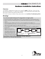
RE E
A BL
W DA
RM A
FI GR
P
U
The In-System Programming (ISP)
Solution for Philips/TEMIC
FLASH 8051 Microcontrollers
USER
GUIDE
(Version 1.10)
User Guide V1.10
Copyright Information
Equinox guarantees that its products will be
free from defects of material and
workmanship under normal use and service,
and that these products will perform to
current specifications in accordance with, and
subject to, the Company’s standard warranty.
It is against the law to copy the software on any
medium except as specifically allowed in the
license or non-disclosure agreement.
The purchaser may make one copy of the
software for backup purposes. No part of this
manual may be reproduced or transmitted in any
form or by any means, electronic, mechanical,
including photocopying, recording, or
information retrieval systems, for any purpose
other than for the purchaser’s personal use,
without written permission.
Equinox reserves the right to change
specifications detailed in this document
without notice and does not represent a
commitment on the part of the manufacturer.
The software described in this document is
furnished under license agreement or
non-disclosure agreement and may be used or
copied only in accordance with the terms of the
agreement.
© 2000 Copyright Equinox Technologies UK Limited. All rights reserved.
Philips is a trademark of Philips Semiconductors
TEMIC Semiconductors is a trademark of TEMIC Semiconductors
Microsoft, MS-DOS, Windows™ and Windows 95™ Windows NT™ are registered
trademarks of the Microsoft Corporation
IBM, PC and PS/2 are registered trademarks of International Business Machines
Corporation
Every effort was made to ensure accuracy in this manual and to give appropriate credit to
persons, companies and trademarks referenced herein.
Disclaimer
All circuit schematics shown in this manual
are offered in good faith. Equinox will not
be liable in any way for any problems
which might arise out of their use.
i
User Guide V1.10
Electromagnetic Compatibility (EMC) Compliance
The GEMINI-1 Programmer is a CE Approved Product. It is designed for use in a development
environment only. This means that the user must ensure that there is no possibility of
damage from electrostatic discharge (ESD). Since the devices and equipment to which this
product is likely to be connected may well themselves be susceptible to ESD, this should not
pose any difficulty.
For example, if you are handling microcontrollers and EEPROMS etc. then you will already be
used to appropriate precautions, such as the use of anti-static mats, wrist straps and so on.
You should treat your GEMINI-1 with the same care as you would these type of device.
Always ensure that you are not yourself carrying a static charge before handling the product.
Wearing an earthed anti-static wrist strap is recommended.
Equinox have taken great care in designing this product to be compliant with the European
EMC directive. When using the equipment be sure to follow the instructions provided.
Although RF emissions are within prescribed limits, care should be taken if you are using the
product near to sensitive apparatus. If you experience any difficulty please refer to Equinox
technical support.
ESD Points to remember
●
Work in a static-free environment.
●
Wear an earthed wrist strap when handling either the programmer
and/or any programmable device.
Please Note:
This equipment is designed for use in a ‘Development Environment’ only and is
NOT guaranteed to operate correctly in a ‘Production Environment’.
Use of this product in a ‘Production Environment’ will invalidate your warranty.
ii
User Guide V1.10
Technical Support
It is often the case that users experience problems when installing or using a product for the first time.
Due to the low-cost nature of this product, Equinox are unable to answer technical support questions
about this product or its use by telephone.
If you have a technical support problem, please consult the following list for help:
1 This manual
2 Troubleshooting Guide (see page 42)
3 On-line help
Press <F1> for help at any time.
The help system is context-sensitive. Simply press <F1> on any error message and the possible
causes of the error should be listed. This help system is updated on a regular basis. Please see
software update details for information on keeping up-to-date with software revisions.
Please note: The help system does not work within Windows 3.11
4 Internet Web Site
Equinox have setup a Philips microcontroller support page on our web site. This page is designed
to provide up-to date information on all issues concerning both Philips microcontrollers and support
tools.
The microcontroller support page can be found at: www.equinox-tech.com/philips.htm
Equinox have also setup a TEMIC Semiconductors microcontroller support page on our web site.
This page is designed to provide up-to date information on all issues concerning both TEMIC
Semiconductors microcontrollers and support tools.
The microcontroller support page can be found at: www.equinox-tech.com/temic.htm
5 E-mail
Please e-mail any technical support questions about this product to: [email protected]
Equinox will try our best to answer your questions about this product as quickly as possible.
However, we can not promise an immediate reply. Please consult our web site for new software
updates as the problem that you are enquiring about may have already been fixed in a new version.
6 Fax
Please fax any technical support questions about this product to: +44 (0) 1204 535555
Equinox will try our best to answer your questions about this product as quickly as possible.
However, we can not promise an immediate reply. Please consult our web site for new software
updates as the problem that you are enquiring about may have already been fixed in a new version.
iii
User Guide V1.10
Contacts
Equinox Technologies UK Limited
3 Atlas House, St George's Square, Bolton, England BL1 2HB
Telephone Sales ....................... : +44 (0) 1204 529000
Fax ........................................... : +44 (0) 1204 535555
E-mail ...................................... : [email protected]
Web site .................................. : www.equinox-tech.com
For technical support on this product please e-mail us at:
[email protected]
Software Updates
In line with our policy of continuous improvement, the ‘Gemini’ software is updated on a
regular basis. The firmware of the actual programmer is also periodically updated. If you
would like to receive an automatic e-mail every time a new version is released, please make
sure you have registered your system with Equinox and you have quoted your e-mail address.
You may cancel this service at any time.
The Gemini software updates can currently be downloaded from the following
places:
Internet
: http://www.equinox-tech.com
Select <Software> This will take you to the software download page
iv
User Guide V1.10
About Philips Microcontrollers
Philips manufacture a complete family of In-System Programmable (ISP) 8051 FLASH
microcontrollers each with different sizes of FLASH & SRAM. Data sheets for these devices
can be viewed and printed using the Acrobat pdf reader software supplied on the Philips
CD-ROM. As data sheets are updated on a regular basis, it is recommended that you consult
the Philips web site for the latest information.
A few sources of further information about Philips microcontrollers are listed below:
Philips web site
: http://www.philips.com
Equinox web site
: http://www.equinox-tech.com/philips.htm
If you have any silicon related technical support question about Philips 8051 FLASH
microcontrollers which can not be answered by looking at the Philips/Equinox web sites,
please e-mail us with a detailed description of the problem at: [email protected]
Important - Please note
Equinox Technologies are unable to answer direct technical support questions concerning
Philips microcontrollers. Please contact your local Philips distributor or sales office if you
require any further information.
v
User Guide V1.10
About TEMIC Semiconductors Microcontrollers
TEMIC Semiconductors manufacture a complete range of OTP, EPROM and 8051 FLASH
microcontrollers. As data sheets are updated on a regular basis, it is recommended that you
consult the TEMIC Semiconductors web site for the latest information.
A few sources of further information about TEMIC microcontrollers are listed below:
TEMIC Semiconductors web site : http://www.temic-semi.com
Equinox web site
: http://www.equinox-tech.com/temic.htm
If you have any silicon related technical support question about TEMIC Semiconductors 8051
FLASH microcontrollers which can not be answered by looking at the TEMIC
Semiconductors/Equinox web sites, please e-mail us with a detailed description of the
problem at: [email protected]
Important - Please note
Equinox Technologies are unable to answer direct technical support questions concerning
TEMIC Semiconductors microcontrollers. Please contact your local TEMIC Semiconductors
distributor or sales office if you require any further information.
vi
User Guide V1.10
Contents
Introduction.....................................................................................1
Device Support - Philips Microcontrollers.....................................2
Device Support - TEMIC Microcontrollers .....................................3
System Specifications .....................................................................4
Hardware Overview........................................................................5
Hardware/Software Installation Overview ..................................6
Gemini for Windows Overview .....................................................7
Hardware Installation Instructions ................................................8
Serial Port Selection......................................................................10
Software Overview.......................................................................11
Device Programming Guide - Philips Microcontrollers .............13
Device Programming Guide - TEMIC Microcontrollers ..............18
Target Settings ..............................................................................23
Target System - ISP Design Requirements ..................................29
ISP Target System Design Guide - Philips Microcontrollers .......33
ISP Target System Design Guide - TEMIC Microcontrollers .......37
Target System Requirements .......................................................40
Gemini-1 Compatible Target Systems .........................................41
Troubleshooting Guide .................................................................42
Error Messages..............................................................................43
PC Serial Cable Connections.........................................................45
Microcontroller Timing Characteristics........................................46
Upgrading the Programmer Firmware ........................................49
viii
User Guide V1.10
Introduction
GEMINI-1 DEVICE PROGRAMMER
HIGHLIGHTS
The GEMINI-1 is a state-of-the-art
development programmer supporting the
new range of In-System Programmable (ISP)
microcontrollers from Philips
Semiconductors and TEMIC
Semiconductors. These microcontrollers
feature serially downloadable memory
allowing the CODE to be updated in-system
without physically removing the target
device from the application board. The
serial programming is via the on-chip UART.
Supports In-System Programming (ISP) of
the following microcontroller families:
• Philips P89C51Rx+ (+12V Vpp)
• Philips P89C51Rx2 (No Vpp required)
• TEMIC T89C51RD2 (No Vpp required)
• Powerful ‘GEMINI’ programmer
interface software:
• Compatible with Windows 95, 98 and NT
• Device commands include Check Signature,
General notes
Blank Check, Erase, Read, Write, Verify, Security,
The Gemini programmer:
Auto-program
• Supports the ISP (In-System Programming)
mode only.
• Powerful buffer system with Blank Check, Erase,
• Automatically writes 00h into the ‘Status
Byte’ and ‘FCh’ into the ‘Boot Vector’ at
the end of every programming operation.
• Supports reading and writing of target device
Fill, Goto and Checksum commands
fuse bits and lock bits
• Supports Binary and Intel HEX file formats
• User-configurable
• Does NOT support custom ‘Boot Loaders’
using the ‘IAP’ (In Application Mode)
~ RESET polarity
~ RESET timing state machine
• Will only operate with a Vcc between
4.8V and 5.8V
~ Target Baud Rate
• Context-sensitive help system
• Does NOT support block ERASE or
READ/WRITE of the target microcontroller
FLASH memory.
• Field upgradable firmware via
Internet downloadable utility caters for new programmer
algorithms in the future
Please Note:
• On-board Vpp generator (+12V)
This programmer is designed for development
use only.
• Programmer ‘Active’ signal - used to
drive an LED on the target system
• Connects to spare PC COM (serial)
port
• Robust ‘EMC-friendly’ design plus
I/O pin protection
• CE compliant product
Order Code: EQ-GEMINI-1 (4.8-5.8V)
1
User Guide V1.10
Device Support - Philips Microcontrollers
Philips FLASH 8051 Microcontroller Families
Device
FLASH Code
Size (Bytes)
SRAM
(Bytes)
I/O Pins
Vpp
(Note 1)
Programming
Mode Supported
P89C51RB2
16K
512
32
+5V
ISP
P89C51RC2
32K
512
32
+5V
ISP
P89C51RD2
64K
1K
32
+5V
ISP
Figure 1
Device
FLASH Code
Size (Bytes)
SRAM
(Bytes)
I/O Pins
Vpp
(Note 2)
Programming
Mode Supported
P89C51RC+
32K
512
32
+12V
ISP
P89C51RD+
64K
1K
32
+12V
ISP
Figure 2
KEY: ISP = In-System Programming Mode
Note 1 - Vpp issues
The Gemini programmer outputs a continuous +5V Vpp to the PROG_VPP pin when a
P89CRx2 device is selected. If the target microcontroller ‘EA/Vpp pin is connected to the
target Vcc, the the PROG_VPP pin need not be connected at all.
Note 2 - Vpp issues
The Gemini programmer generates a +12V Vpp on-board the programmer for the
P89C51Rx+ devices and switches this voltage to the PROG_VPP pin during programming.
Note 3 - 6 Clock/12 Clock Oscillator Modes
The P89CRx2 microcontroller family are shipped from the factory with ‘6 Clock’ mode
enabled. This means that the device is configured to use 6 clocks per machine cycle i.e. twice
as fast as the generic 8051 core.
It is NOT possible to use the Gemini programmer to change the ‘6 Clock / 12 Clock’
selection. This operation can only be performed using the ‘Parallel Programming Algorithm’
which is available on the Equinox ‘Micro-Pro PLUS’ programmer.
2
User Guide V1.10
Device Support - TEMIC Microcontrollers
TEMIC Semiconductors FLASH 8051 Microcontroller Families
FLASH Code
Size (Bytes)
E2PROM
SRAM
(Bytes)
I/O
Vcc
(Note 2)
Vpp
(Note 1)
Prog Mode
Supported
T89C51RD2-M
64K
2K
1280
32-48
4.5-5.5V
No (Internal)
ISP
T89C51RD2-L
64K
2K
1280
32-48
2.7-5.5V*
No (Internal)
ISP
Device
Figure 3
KEY: ISP = In-System Programming Mode
Note 1 - Vpp issues
• T89C51RD2 devices generate Vpp internally from the standard Vcc. Simply connect EA to
Vcc to enter ISP mode. Applying a voltage higher than Vcc to the EA pin may damage the
device.
Note 2 - Vcc issues
• The Gemini programmer does not support operation below 4.8V
Temic T89C51RD2 microcontroller features
• The last 1K of T89C51RD2 Flash is used for ISP/IAP firmware and cannot be changed by
ISP. A parallel programmer is needed to change this area.
• Hardware lock bits cannot be changed by ISP.
The TEMIC devices feature ‘Software’ and ‘Hardware’ lock bits. The ‘Hardware’ lock bits
can only be programmed using a ‘parallel’ programmer. The ‘software’ lock bits can be
programmed using the Gemini ISP programmer. The FLASH code area can not be
modified anymore once the ‘software’ lock bits are set without first performing a ‘Chip
Erase’ operation using a parallel programmer.
NOTE:
Once you have locked the device in ISP mode, you can not unlock it except by physically
removing it from your target system and erasing it in a parallel programmer.
• The FLASH code can be reprogrammed in pages or one byte at a time without needing
a block erase. The programmed bytes are automatically erased before programming.
• The Temic devices allow the ‘6 Clock or 12 Clock’ to be dynamically changed by
software in the user application. The T89C51RD2 is always configured in 12 Clock mode
after RESET and during ISP.
3
User Guide V1.10
System Specifications
Minimum System Contents
•
•
•
•
•
GEMINI-1 Serial Download Programmer
PC Serial extension cable set
Windows Driver Software (Gemini)
CD-ROM
GEMINI-1 User Guide
Please note: Target system is NOT included
GEMINI-1 Serial Programmer Specifications
Programmer Size
: 55 x 53 x 16mm
Shipped Weight
: Approx 0.10kg
PC Connection
: Serial Port 25-pin female D Connector
Programming Cable : Length 300mm
Header
: 10-way IDC 0.1” pitch bump polarised
Power Supply
: Requires power from target system or external power supply (Not
supplied)
Vpp Voltage
: +12V (Generated by the programmer when required)
GEMINI-1 Vcc: 4.8 - 5.8V
- Is (supply) approx 50mA when programming
- Is (supply) approx 27mA in standby
- Is (supply) approx 700mA inrush current when Vpp generator
is switched on
Minimum PC requirements
The minimum hardware and software requirements to ensure that the programmer operates
correctly are as follows:
•
•
•
•
•
100% IBM compatible 386+
Windows 95, 98 & NT4
Minimum 4MB RAM
Minimum 1MB free hard disk space
Spare PC COM (Serial) port
4
User Guide V1.10
Hardware Overview
Red stripe (denotes pin 1)
5
6
2
3
Figure 4
4
1
Key
1
2
3
4
5
6
GEMINI-1 Programmer
In System Programming (ISP) Cable (length approx 300mm)
10-way IDC Header Plug
25 pin female D-Connector (plugs into PC COM Port)
Power LED
Active LED
5
User Guide V1.10
Hardware/Software Installation Overview
The Hardware/Software Overview for the installation process of the GEMINI-1 programmer is
detailed diagrammatically below. Please refer to the following pages for a more detailed
explanation.
Perform Software Installation
Perform Hardware Installation
Select the correct serial port
<OPTIONS>
<SELECT PORT>
Try selecting
another
Com port
Installation
Trouble Shooting
Guide
(See on-line help)
<TEST>
PORT
FAIL
PASS
Programmer should now be
“ON LINE”
Figure 5
6
User Guide V1.10
GEMINI for Windows Overview
To Install 'Gemini for Windows'
software:
The GEMINI-1 programmer is supplied with
'GEMINI for Windows' PC driver software.
This software is supplied on one 3.5"
floppy disk or can be downloaded from the
Equinox web site.
• Boot the PC into Windows environment
•
GEMINI-1 Programmer Interface
Software
•
• Powerful Windows Programmer Interface
Software compatible with
Windows 95™, Windows 98™ &
Windows NT™
•
•
•
• Device: Check, Signature, Erase, Blank
Check, Read, Program, Verify, Special
Options and Security
(Win 95 or NT)
Insert 'GEMINI for Windows' disk into
floppy disk drive (A: / B:)
Select the 'Run...' command from the
'File' menu in the Program Manager
Select 'Browse' and navigate to the
floppy drive (A: / B:)
Select 'gemini.exe'
Select the 'OK' button
The software installation program should
now display an introductory screen. Please
follow the on-screen prompts in order to
complete the software installation process.
• Programmable RESET polarity
• Powerful RESET Timing utility allows most
RESET circuits to be accommodated
including C/R, External Watchdog and
3-pin CPU supervisor devices
On completion, the installation program will
install the 'GEMINI' icon within a new
program group called 'Equinox'.
• Powerful Auto-Program Utility
• Fast programming times
To launch the software,
simply double-click on the
'GEMINI' icon.
• Supports Bin & HEX file formats
• Supports Reading/Clearing of the
Status Byte
• Comprehensive context-sensitive on-line
help system
7
User Guide V1.10
Hardware Installation Instructions
Overview
The GEMINI-1 programmer connects to any spare PC serial (COM) port. If you only have
one serial port and this is in use for e.g. a modem, it may be possible to add another serial
port to your machine by inserting a new I/O card.
For further hardware installation help, please refer to the: Installation Troubleshooting Guide
Warning!
To avoid catastrophic damage to PC, programmer or target system:
• Ensure that both your target system and PC are connected to a common earth point.
• Make sure that all interconnections are made before applying power to PC and target
system.
• If you are using a laptop or PC which is not connected to mains earth, it is
recommended that you make a hard-wired connection from the COM port D-connector
shell and the target system to a common earth point.
• Avoid plugging and unplugging ISP connector while either the PC or target system is
powered up.
• Please ensure that any
devices connected to the
user target system are also
properly grounded to the
same common earth point.
• Please see Diagram opposite
Serial Cable
User
Target
System
GEMINI-1
PC
1
2
1 Earth connection to PC
2 Target system earth
3 Earth from external device
3
Common earthing point
Any damage caused to the programmer through inadequate
earthing is not covered under warranty.
8
External
Devices
Figure 6
User Guide V1.10
Hardware Installation Instructions continued
Installation Instructions
See Figure 6
1 Ensure power to both PC and target systems is switched off.
2 Connect the serial cable provided to a spare COM port on the PC using the 9-25 way
adaptor if necessary.
3 Connect the GEMINI-1 to the other end of the serial cable.
4 Connect the IDC plug at the end of the ISP cable into the 10-way IDC header on the user
target board (not supplied).
NOTE: The PC serial cable used must be of the same specification as the one supplied
with the system. Failure to use the correct serial cable may result in the programmer not
working.
5 Apply power to the target board. Please ensure that the target system is powered up.
The programmer will not operate unless a Vcc in the specified range is applied on pin 1 of
the IDC connector. (The GEMINI-1 draws its power from the target)
Warning!
The Gemini programmer features an on-board Vpp generator circuit which produces a Vpp
of +12V on the Vpp pin of the programmer under control of the Gemini driver software.
Please take the following points into consideration when using the programmer:
1 The programmer will always output Vcc on the Vpp line, except during programming of
a Philips P89C51Rx+ device.
2 If the selected devices requires a Vpp of +12V to be applied, the programmer will switch
the Vpp line from Vcc to +12V to commence the programming operation. This voltage
will only be released at the end of the programming operation.
3 When the programmer switches on the Vpp generator, a large surge current is drawn
from the target system supply. This can be as high as 700mA for a period of a few
milliseconds. If your target system can not supply this inrush current, you may find the
target system power supply current limits and the programming operation will fail. In
these circumstances, it is necessary to use an external power supply which can cope with
the inrush current. This problem will only occur with the Philips P89C51Rx+ family which
require the +12V Vpp.
9
User Guide V1.10
Serial Port Selection (Select Port)
The GEMINI-1 programmer plugs into a
spare serial (com) port of any IBM
compatible PC including the majority of
laptop machines.
This tests both the programmer, cable and
PC serial port. It does not communicate
with the target microcontroller.
Communications Test-Pass
To select the Correct Serial Port
The available COM ports on your computer
are now displayed.
The programmer has been detected OK by
the GEMINI software. If you now <Cancel>
out of the <Test Port> dialogue box, the
words ‘ON LINE’ should now be displayed at
the bottom right of the GEMINI Window.
ii. Select the COM port to which the
programmer is connected
Installation is complete and the programmer
should now be ready to-use.
ii. Select the desired target microcontroller
baud rate e.g. 9,600
Please Note:
i.
From the menu bar select <Options>
<Select Port>
• This test has not verified that the
programmer can communicate with the
target microcontroller.
The baud rate is the maximum baud
rate which the target microcontroller
can reliably communicate at.
See Device programming section for
further information.
• Changing the baud rate will have no
effect on the ‘Communications Test’.
iii. Select <Test>
A programmer communications test is
now performed.
Communications Test-Fail
The programmer was not detected on the
COM port selected. Please check the
following:
• The correct COM port was selected, and
if not, repeat the <Select Port> < Test>
operation.
• The correct PC serial cable has been
used as supplied with the programmer.
If the programmer is still not detected,
please refer to the Installation
Troubleshooting Guide located in the
“On-Line” help.
Figure 7
Figure 8
10
User Guide V1.10
Software Overview
The GEMINI for Windows™ software features many powerful functions which can be
activated by simply clicking a single icon. Other utilities and commands are available by
selecting the relevant menu option.
For further information about the GEMINI for Windows™ software, please refer to the
'On-line Help System' supplied with the software (F1).
The most commonly used functions for which an icon exits are listed below.
LOAD FILE TO BUFFER (F9 or Ctrl + L)
Allows you to select a file or multiple files and load the file(s) into the
programmer buffer area(s). Currently supports Intel Hex and Binary file
formats as standard.
SAVE TO DISK (Ctrl + S)
Allows you to save the contents of the buffer(s) to a file.
Currently supports Intel Hex and Binary file formats as standard.
BLANK CHECK
Checks if the currently selected device is blank.
i.e. All locations = FFh
VERIFY DEVICE
Compares the contents of the buffer area(s) with the contents of the
currently selected device.
WRITE DEVICE
Writes with contents of the buffer into the device
Note:
This operation does NOT perform an electronic erase before writing
data.
11
User Guide V1.10
Software Overview continued
DEVICE READ
Reads the contents of the currently selected device into the
programmer buffer area(s).
ERASE DEVICE
Performs an ELECTRONIC erase on the currently selected device.
DEVICE AUTO-PROGRAM
Performs a complete programming cycle including Signature Check,
Erase, Blank check, Write, Special Options, Security etc.
SECURITY
Allows you to READ/WRITE the security lock bits of any device which
supports this feature.
12
User Guide V1.10
Philips Device Programming Guide
The GEMINI-1 Programmer is now ready to program a target device.
In the following example we have chosen to program a Philips P89C51RC+IN
microcontroller on the user target system.
1
In GEMINI select <Options> <Create Library Info>
This operation interrogates the target programmer and generates a ‘notepad’ document
which details information about your programmer and generates a list of devices
supported by the programmer. From the list you can see which ‘TARGET ISP’ devices can
be programmed with the GEMINI-1. i.e. only devices listed as ‘yes’ or LNR’ are supported.
2
Select your target device from <Device><Select>...
In our example this is <Philips><P89C51Rx+>
<P89C51RC+ ISP>
Warning!
The programmer applies +12V to the Vpp pin of the target
microcontroller if a Philips P89C51Rx+ device is selected by
mistake.
This could cause damage to both the target microcontroller
and target system if the microcontroller is actually a
+5V Vpp version.
3 From the <Device menu>, select<Information>
This will give you a description of the target device.
4 Select the frequency of the target microcontroller
- Select <Options><Target settings...>.
- Adjust Fosc to the
frequency your target
microcontroller is
running at.
(Note: The value of
Fosc is rounded down
to the nearest integer
MHz value.)
Figure 9
Note:
If you are using different
reset timings to the
default settings refer to
Target Settings section,
page 23
Figure 10
13
User Guide V1.10
Philips Device Programming Guide continued
5
Setting of Baud Rate and COM Port
- Choose <Options><Select Port>
- Select the COM port to which your GEMINI-1
programmer is connected.
- Select the required target baud rate to
communicate with the target microcontroller.
Figure 11
The default is 9,600 baud which should work
reliably for most target systems.
If you wish to minimise the programming time, the baud rate may be increased. The
reliability of the programming operation depends on the target device and, to some
extent, the speed of the PC. Please refer to the ‘Microcontroller Timing Characteristics
Section’ on page 46 for further information.
6
Performing a ‘Signature Check’ of the target device
A quick check to make sure that the programmer is able to communicate with the target
device is to perform a ‘Signature Check’ operation.
- Select <Device><Check Signature>
-> The yellow ‘Active’ LED on the programmer should illuminate
-> The ‘Device Signature (ID) should be read from the target device and validated:
• PASS: Signature matches selected device
• FAIL: Incorrect signature - The wrong device may have been selected.
• Device not responding: Programmer could not communicate with target device.
(See Error Messages section)
7
Loading user code to the buffer area
To program the target system with real data, the buffer must first be loaded with the
user code.
- Select <File><Load to Buffer...>
The ‘Load to Buffer’ dialog as shown in Figure 12
-
To load a file into the code area, click <Browse...> in the code section
Select the required file (*.hex or *.bin)
Click <Load>
Click <Ok> to quit the ‘Load dialog box’.
Please note: The current Philips microcontrollers do not feature an EEPROM (Data)
Section, so the ‘Data’ dialogue has been greyed out.
14
User Guide V1.10
Philips Device Programming Guide continued
Load to Buffer (Buttons etc., explained)
1
4
2
5
3
6
Figure 12
1 Automatic Range - Automatic selection of the file start and end address.
2 Erase Buffer
- Erases the entire buffer before loading the new file into it.
3 Load
- Loads the selected file into the buffer.
4 Browse
- Allows you to browse and select a file.
5 Preview
- Previews the file (address, size, checksum) without loading it to the
buffer.
6 Exit
- Exit this window.
15
User Guide V1.10
Philips Device Programming Guide continued
8
Using <Auto-Program> to program a target device
The most straightforward method of programming a target device is to select
<Device><Auto-Program> or click the <Auto-Program> icon.
An ‘Auto-Program’ performs the following actions:
-
Pre-programming State Machine operations
Check Signature
Chip Erase
Blank check
Write CODE area
Verify Pass 2 (Default: OFF)
Write special Options (Status Byte)
Write Security
Please note:
The ‘Status Byte’ is automatically cleared to zero at the end of any programming
operation. This makes sure that the user target code starts execution the next time the
device comes out of RESET.
9
Using the <Device> commands individually
It is possible to initiate any programmer command individually from the <Device> menu.
Please note:
i. The programmer will, by default, perform a ‘Pre-programming State machine’ operation
and a ‘Check Signature’ for each operation selected. The ‘Check Signature’ can be
disabled using a tick box in the <Options><Advanced> menu.
ii. The <Device><Write> operation does not perform a ‘Chip Erase’ operation. If there is
already non-FF data in the target device, then the ‘Write’ operation will fail. A manual
<Device><Erase> is required to erase the device.
iii. The <Device><Special Options> operation allows the user to read the current value of
the ‘Status Byte’ from the target device. New values can also be written to the target
device.
16
User Guide V1.10
Philips Device Programming Guide continued
10 Reading/Writing the Status Byte
It is possible to Read/Clear the
‘Status Byte’ using the
<Device><Special Options>
dialog as shown in figure 13.
To read the current value of
the ‘Status Byte’:
• Click the <Read> button
-> The programmer enters ISP
mode, reads the ‘Status Byte’
value and displays it.
Figure 13
To clear the ‘Status Byte’:
• Check the ‘Clear Status Byte’ option
• Click the <Write> button
-> The programmer enters ISP mode, writes 00h to the ‘Status Byte’ and then exits ISP
mode
11 Security
It is possible to Read/Write the security lock bits using the <Device><Security> dialogue.
Level
0
1
2
3
Function
No program lock
Further programming disabled
Programming & verify disabled
External execution disabled
Note
You can only increase the security level. In order to return to security level 0 you will
have to use <Device><Erase>
17
User Guide V1.10
TEMIC Device Programming Guide
The GEMINI-1 Programmer is now ready to program a target device.
In the following example we have chosen to program a TEMIC T89C51RD2 microcontroller
on the user target system.
1
In GEMINI select <Options> <Create Library Info>
This operation interrogates the target programmer and generates a ‘notepad’ document
which details information about your programmer and generates a list of devices
supported by the programmer. From the list you can see which ‘TARGET ISP’ devices can
be programmed with the GEMINI-1. i.e. only devices listed as ‘yes’ or LNR’ are supported.
2
Select your target device from <Device><Select>...
In our example this is <Temic><T89C51Rx2>
<T89C51RD2>
Warning!
The programmer applies +12V to the Vpp pin of the target
microcontroller if a Philips P89C51Rx+ device is selected by
mistake.
This could cause damage to both the target microcontroller
and target system.
3
From the <Device menu>, select<Information>
This will give you a description of the target device.
Note:
If you are using different reset timings to the default
settings refer to Target Settings section, page 23
Figure 14
18
User Guide V1.10
TEMIC Device Programming Guide continued
4
Setting of Baud Rate and COM Port
- Choose <Options><Select Port>
- Select the COM port to which your GEMINI-1
programmer is connected.
- Select the required target baud rate to
communicate with the target microcontroller.
Figure 15
The default is 9,600 baud which should work
reliably for most target systems.
If you wish to minimise the programming time, the baud rate may be increased. The
reliability of the programming operation depends on the target device and, to some
extent, the speed of the PC. Please refer to the ‘Microcontroller Timing Characteristics
Section’ on page 47 for further information.
5
Performing a ‘Signature Check’ of the target device
A quick check to make sure that the programmer is able to communicate with the target
device is to perform a ‘Signature Check’ operation.
- Select <Device><Check Signature>
-> The yellow ‘Active’ LED on the programmer should illuminate
-> The ‘Device Signature (ID) should be read from the target device and validated:
• PASS: Signature matches selected device
• FAIL: Incorrect signature - The wrong device may have been selected.
• Device not responding: Programmer could not communicate with target device.
(See Error Messages section)
6
Loading user code to the buffer area
To program the target system with real data, the buffer must first be loaded with the
user code.
- Select <File><Load to Buffer...>
The ‘Load to Buffer’ dialog as shown in Figure 16
-
To load a file into the code area, click <Browse...> in the code section
Select the required file (*.hex or *.bin)
Click <Load>
Click <Ok> to quit the ‘Load dialog box’.
Please note: The current TEMIC microcontrollers do not feature an EEPROM (Data)
Section, so the ‘Data’ dialogue has been greyed out.
19
User Guide V1.10
TEMIC Device Programming Guide continued
Load to Buffer (Buttons etc., explained)
1
4
2
5
3
6
Figure 16
1 Automatic Range - Automatic selection of the file start and end address.
2 Erase Buffer
- Erases the entire buffer before loading the new file into it.
3 Load
- Loads the selected file into the buffer.
4 Browse
- Allows you to browse and select a file.
5 Preview
- Previews the file (address, size, checksum) without loading it to the
buffer.
6 Exit
- Exit this window.
20
User Guide V1.10
TEMIC Device Programming Guide continued
7
Using <Auto-Program> to program a target device
The most straightforward method of programming a target device is to select
<Device><Auto-Program> or click the <Auto-Program> icon.
An ‘Auto-Program’ performs the following actions:
-
Pre-programming State Machine operations
Check Signature
Chip Erase
Blank check
Write CODE area
Verify Pass 2 (Default: OFF)
Write special Options (Status Byte)
Write Security
Please note:
i The ‘Status Byte’ is automatically cleared to zero at the end of any programming
operation. This makes sure that the user target code starts execution the next time
the device comes out of RESET.
8
Using the <Device> commands individually
It is possible to initiate any programmer command individually from the <Device> menu.
Please note:
i
The programmer will, by default, perform a ‘Pre-programming State machine’
operation and a ‘Check Signature’ for each operation selected. The ‘Check Signature’
can be disabled using a tick box in the <Options><Advanced> menu.
ii The <Device><Write> operation does not perform a ‘Chip Erase’ operation. The
TEMIC device automatically erases the programmed bytes before programming and a
manual <Device><Erase> is not required.
iii The <Device><Special Options> operation allows the user to read the current value of
the ‘Status Byte’ from the target device. New values can also be written to the target
device.
21
User Guide V1.10
TEMIC Device Programming Guide continued
9
Reading/Writing the Status Byte
It is possible to Read/Clear the
‘Status Byte’ using the
<Device><Special Options>
dialog as shown in figure 18.
To read the current value of
the ‘Status Byte’:
• Click the <Read> button
-> The programmer enters ISP
mode, reads the ‘Status Byte’
value and displays it.
Figure 17
To clear the ‘Status Byte’:
• Check the ‘Clear Status Byte’ option
• Click the <Write> button
-> The programmer enters ISP mode, writes 00h to the ‘Status Byte’ and then exits ISP
mode
10 Security
It is possible to Read/Write the security lock bits using the <Device><Security> dialogue.
Level
0
1
2
Function
No program lock
Further programming disabled
Programming & verify disabled
Note
You can only increase the security level. In order to return to security level 0 you will
have to use <Device><Erase>
22
User Guide V1.10
Target Settings
Overview
Prog-Active Polarity
The Gemini programmer programs a target
microcontroller using the In System
Programming (ISP) mode. This involves the
programmer forcing the target
microcontroller to execute the ‘ISP Boot
Loader’ firmware which is embedded in the
target device at the factory.
Target
Oscillator
Frequency
RESET
Polarity
The user must specify the following
information about the target system:
Timing
Parameters
i What frequency the target device is
running at (Fosc)?
ii What RESET polarity the target system
requires?
Figure 18
iii What timings are used to enter and exit
ISP mode?
Target Fosc setting
The Target Fosc setting is not necessary for the TEMIC T89C51Rx2 devices. Although it can
be set, the microcontroller firmware disregards the value.
For Philips devices the programmer communicates with the target microcontroller using the
on-chip 8051 UART. The user must tell the programmer what oscillator frequency the target
system is running at. The Gemini software sends this value down to the target
microcontroller where the ‘Boot Loader’ code uses the oscillator frequency value to autodetect the baud rate from the PC.
Please note:
The Gemini software allows you to enter any value in the Fosc box. However, this value will
be automatically rounded down to the nearest integer MHz value when a programming
operation is initiated.
23
User Guide V1.10
Target Settings continued
Overview
The Gemini programmer has been designed to support most common 8051 target system
RESET circuit scenarios. The timings used to enter and exit ‘Serial Programming Mode’ are
user-programmable using the <Options><Target Settings> dialogue box. This dialogue allows
the RESET polarity, hold time and release time to be altered. The characteristics of the Vpp
generator can also be adjusted within this menu.
RESET Polarity
An 8051 microcontroller requires an ‘Active
HIGH’ reset signal. i.e. to reset the device,
the programmer must assert the RESET pin
HIGH. The Gemini programmer features
user-selectable RESET polarity which caters
for both standard C/R RESET circuits and
also more complicated RESET circuits which
may require an ‘Active LOW’ signal.
Vcc
R3
PB
C1
Connect to
µC RESET
circuit
RESET
R1
R2
0V
RESET circuit
Reset Polarity
C/R Network
Active HIGH
Watchdog IC
Check relevant data sheet
Figure 19
PROG_ACTIVE Polarity
The PROG_ACTIVE line can be used to warn
the target microcontroller that the RESET pin
is about to be asserted. If an LED on the
target system is connected to the
PROG_ACTIVE line of the programmer, the
polarity should be set to ‘Active LOW’. The
LED will illuminate when the programmer
asserts the PROG_ACTIVE line at the start of
the programming sequence.
Vcc
R1
PROG_ACTIVE
Figure 20
24
User Guide V1.10
Target Settings continued
Order of events
The programmer executes a specific sequence of events in order to enter ‘Serial
Programming Mode’. If the selected target device requires a Vpp to be applied, this voltage
will be generated from the programmer. If the target device does not require a Vpp voltage,
the programmer will apply a continuous +5V voltage to the Vpp pin.
Action
Description
1
User selects a programming operation
2
The programmer asserts the PROG_ACTIVE pin.
RESET pin remains tri-stated.
3
Programmer waits for period T1.
This time could be used for the target microcontroller to safely close down any
tasks such as writing to an external EEPROM.
4
Programmer asserts the PROG_RESET pin.
The target microcontroller enters the RESET state.
User code execution is halted.
5
Programmer waits for period T2.
6
Programmer switches on the Vpp generator circuit and connects the output of
the Vpp generator circuit to the PROG_VPP pin.
This applies the Vpp voltage to the target system.
7
Programmer waits for period T4.
This delay must be long enough to allow the Vpp voltage to reach and stabilise at
the specified value.
8
Programmer tri-states the PROG_RESET pin.
If a C/R RESET circuit is used on the target system, the RESET line will decay
exponentially as the RESET capacitor discharges through the RESET
resistance.
If a watchdog IC is used, the target circuit design must ensure that the
RESET line is released properly as this line is not driven by the programmer
when deasserted.
Figure 21
25
User Guide V1.10
Target Settings continued
Action
Description
9
Programmer waits for period T3.
- This time allows the target system RESET to reach 0V.
During this period, the target microcontroller will start to execute code.
The target microcontroller will jump to the address pointed to by the ‘Boot
Vector’ and will then jump to the ‘Boot Loader’ code.
10
Programmer send the character ‘U’ to the target microcontroller to initiate ‘Serial
Programming Mode.
The programmer should now be able to communicate with the target
microcontroller ‘Boot Loader’ code.
11
The programmer sends the relevant command or series of commands to the
target microcontroller.
The target microcontroller should send back the required response(s) to the
ISP commands sent by the programmer.
12
The programmer asserts the PROG_RESET pin again.
13
Programmer waits for period T2
14
Programmer switches off the Vpp generator.
The voltage on the PROG_VPP starts to decay from +12V to +5V
15
Programmer waits for period T5.
This delay allows the Vpp voltage to decay from +12V to a stable +5V level.
16
The programmer performs the following actions:
Writes the value ‘00h’ into the ‘Status Byte’
Writes the value ‘0FCh’ into the ‘Boot Vector’
Tri-states the PROG_RESET pin.
17
Programmer waits for period T3.
- This time allows the target system RESET to reach 0V.
During this period, the target microcontroller will start to execute code.
The target microcontroller will jump to address 0000h and start execution of
the user firmware.
Figure 21 continued
26
User Guide V1.10
Target Settings continued
Programming waveforms for a P89C51RC+ device
12V (Vpp)
EA/Vpp
(PROG_Vpp)
5V (Vcc)
5V
RESET
0V
PROG_ACTIVE
(PROG_RESET)
5V
0V
Parameters
see figure 24
Actions
see figure 22 1
2
T1 T2
T4
T3
3
7
9
5
4
6
8
11
10
T2
T5
T3
13
15
17
12 14
16
Figure 22
Notes:
1 For Philips P89C51Rx2 devices, the ‘EA/Vpp’ voltage will remain at +5V (i.e. Vcc) at all
times.
2 For TEMIC T89C51RDx devices, the ‘EA/Vpp’ voltage will remain at +5V (i.e. Vcc) at all
times.
27
User Guide V1.10
Target Settings continued
Timing Parameters
The Gemini software allows you to set up all of the relevant timings for entering and exiting
‘Serial Programming Mode’. The default timings for T1...T6 have been chosen to suit a C/R
network.
Parameter
Description
Default (ms) Min (ms)
Max (ms)
T1
Safe Shutdown Delay
Time between the PROG_ACTIVE line
being asserted to the PROG_RESET being
asserted
200
1
4,000
T2
RESET Hold Time
Time from RESET being asserted to the
Vpp generator being switched on or off
(if Vpp is required)
200
1
4,000
T3
RESET Release Time
Time allowed for the target RESET circuit
to decay from Vcc to 0V once the
PROG_RESET line is released (i.e. tri-stated).
500
1
4,000
T4
Vpp Ramp Up Time
Time allowed for the Vpp generator
voltage to ramp up and settle at the final
specified Vpp value.
500
1
4,000
T5
Vpp Ramp Down Time
This is the time allowed for the Vpp
generator voltage to ramp down from the
specified Vpp value to Vcc.
1,000
1
4,000
T6
Reserved for future use
-
-
-
Figure 23
28
User Guide V1.10
Target System - ISP Design Requirements
Overview
The Philips P89C51Rx+, P89C51Rx2 and TEMIC T89C51Rx2 microcontroller families feature
on-chip FLASH CODE memory which may be in-system programmed (ISP) using the Gemini
ISP programmer. To facilitate ISP on your target system, it is necessary for you to bring out
certain connections from the target microcontroller to a header on your PCB. The Gemini ISP
cable plugs into this header allowing the programmer to assert the correct signals.
Serial Cable
PC
User
Target
System
GEMINI-1
1
1 Earth connection to PC
2 Target system earth
3 Earth from external device
2
External
Devices
3
Common earthing point
Figure 24
Notes:
• The programmer requires a minimum of five connections to the target system to facilitate
In-System Programming (TXD, RXD, GROUND, VCC & Vpp).
• The programmer draws power from the target system.
• The programmer features an on-board Vpp generator circuit (i.e. The target system does
not have to generate the Vpp voltage)
• The programmer communicates with the target microcontroller using the 8051 UART
(Serial Port).
• The programmer forces the target microcontroller into ‘ISP’ mode using the ‘Hardware
Activation of the Boot Loader’ technique - ‘IAP’ mode is NOT supported.
• The target microcontroller can execute code when the programmer is connected or
disconnected from the target system.
29
User Guide V1.10
Target System - ISP Design Requirements continued
GEMINI-1 - Target System Connection
Details
10-Way IDC Header
Top Pin View
PROG_Vcc
The programmer 10-way ribbon cable supplied is
terminated with a standard 10-way 0.1" pitch IDC plug.
This is designed to mate with the complimentary male
10-way IDC header on the target system. The pin-out of
the header is shown opposite:
PROG_PSEN
PROG_ACTIVE
PROG_GND
PROG_GND
1
2
3
4
5
6
7
8
9
10
PROG_VPP
PROG_TXD
PROG_RXD
N/C
PROG_RESET
Figure 20
Note: This is the view of the connector fitted to the target
board, as seen from above (the component side).
ISP Pin Assignments
Pin GEMINI-1
Pin Name
Target
Function Description
Microcontroller
Pin Name
1 PROG_Vcc
Vcc
P
Target Vcc connection
2 PROG_Vpp
EA/Vpp
I
Target Vpp pin - Vpp is applied to this pin (if required)
3 PROG_PSEN
PSEN
Driven LOW by programmer to enter ‘Boot Loader’ mode
4 PROG_TXD
RXD
I
Programmer TXD line connects to microcontroller TXD line
5 PROG_ACTIVE LED or Interrupt pin
Programmer Active LED/Interrupt pin
6 PROG_RXD
TXD
O
Programmer RXD line connects to microcontroller TXD line
7 PROG_GND
Vss
P
Target GROUND (Vss) connection
8 N/C
Not Connected
9 PROG_GND
Vss
P
Target GROUND (Vss) connection
10 PROG_RESET RESET
Target RESET control pin or RESET Circuit
KEY: N/C = No Connect I = Input O = Output P = Pause
Figure 25
Connector recommendations
The IDC connector supplied with the GEMINI-1 programmer is ‘bump’ polarised so that it
can not be inserted the wrong way around in a polarised socket. If the connector used on
the target system is not polarised, it is advised that measures are taken to prevent the
connector being plugged in the wrong way around. This could be achieved by removing
pin 8 from the target header and placing a blanking piece of plastic in pin 8 of the
cable header.
30
User Guide V1.10
Target System - ISP Design Requirements continued
Programmer Power Supply Requirements
The programmer draws its power from the target system. To ensure that the programmer
operates reliably, it is imperative that the target power supply meets the voltage and current
requirements of the programmer shown in the ‘Systems Specifications’ section of the manual.
When programming target devices which require a +12Vpp, care should be taken to ensure
that the target power supply can cope with the inrush current as the Gemini ‘Vpp Generator
Circuit’ switches on. Failure to meet these requirement may result in erratic programmer
operation as the programmer will automatically reset itself when an unstable supply is detected.
Power supply design notes:
The suggested circuit shown in figure 26 is capable of reliably supplying +5V to both the target
and the programmer. The capacitors C1,C2,C3,C4 shown must be fitted to ensure that the
regulator does not oscillate. Failure to fit these components can result in spurious oscillations of
the ‘Target Vcc’ supply which can cause the programmer to automatically reset itself. The diode
D1 protects against accidental reverse polarity of the external power supply. The diode D2
protects the regulator in the event of the target system trying to discharge back towards the
power supply input.
Important Note
i Please check that the specification of your target power supply meets the required specification
for the programmer. If you encounter erratic operation of the programmer, please use an
oscilloscope to check that the ‘Target Vcc’ is within limits and that there are no glitches on the
supply. Also, check that the Vcc ripple and noise are within acceptable limits.
ii If you are using the Philips ‘P89C51Rx+ ISP Target Board’ with this programmer, please ensure
that you add capacitors C1 and C2 to the board. Without these components, the target Vcc
oscillates and causes the programmer to continuously reset.
Suggested +5V Target Power Supply
D2
Figure 26
REG1
D1
VIN
External PSU
9V - 25V DC
Regulated
Target Vcc
VOUT
COMMON
C1
C2
C3
C4
Target GND
KEY
REG1 7805
PSU1 Regulated Power Supply 9V-25V DC
C1 100µF 35V Electrolytic
C2 47nF Polyester
31
C3
C4
D1
D2
47nF Polyester
100nF Polyester
Diode e.g. IN4002
Diode e.g. IN4002
User Guide V1.10
Target System - ISP Design Requirements continued
The following target system requirements must be met for the Gemini-1 programmer to
reliably in-system program (ISP) a target microcontroller:
Target Oscillator
The ISP mode of these microcontrollers uses a ‘Boot Loader’ stored in the target
microcontroller. It follows, therefore, that the target microcontroller must be able to execute
the ‘Boot Loader’ firmware. The speed at which the ‘Boot Loader’ firmware is executed
depends on the target oscillator frequency.
To ensure the fastest and most reliable ISP operation, the target oscillator frequency should
be chosen to be the highest value possible within the specification of the device. It is not
necessary to choose a frequency which gives an exact ‘Baud rate’ as the ‘Boot Loader’ is
capable of auto-detecting most baud rates and compensating accordingly.
PROG_ACTIVE Polarity
The PROG_ACTIVE line can be used to warn the
target microcontroller that the RESET pin is about to
be asserted. If an LED on the target system is
connected to the PROG_ACTIVE line of the programmer,
the polarity should be set to ‘Active LOW’. The LED will
illuminate when the programmer asserts the
PROG_ACTIVE line at the start of the programming
sequence.
32
Vcc
R1
PROG_ACTIVE
Figure 27
User Guide V1.10
ISP Target System Design Guide - Philips Microcontrollers
Implementation of ISP on the target system
The circuit schematic shown in figure 29 details the connections required between the
programmer and the target microcontroller. Some connections and components are optional
depending on the device family being used and whether a ‘PROGRAMMER ACTIVE LED is
required on the target system.
Circuit
Label
Description / purpose
U1
U2
Target 89C ISP microcontroller
RS-232 Transceiver IC (optional)
See Note 1
LED current limiting resistor (optional)
Used to discharge C5 when the Vpp (+12V)
is removed.
This resistor prevents output clashes
between the PROG_TXD pin and the output
of the RS-232 Transceiver IC. (optional)
Oscillator capacitor
Oscillator capacitor
Supply decoupling capacitor
Supply decoupling capacitor
Vpp decoupling capacitor
Programmer ‘Active’ LED
Diode to prevent the Vpp (+12V) from
affecting the Vcc supply
Crystal Oscillator
R1
R2
R3
C1
C2
C3
C4
C5
D1
D2
XT1
J1
J2
Recommend Value
Optional jumper
Fitted - connects PROG_VPP from
programmer to EA/Vpp pin of target
microcontroller
Not fitted - completely isolates +12V Vpp
from the target microcontroller.
Optional jumper
For P89C51Rx2 devices, the EA/Vpp pin can
be connected directly to Vcc
Units
eg. P89C51Rx+, P89C51Rx2
eg. MAX232
-
2k7
22k
Ohms
Ohms
4k7
Ohms
33p
33p
1u
100n
47n
LED
eg. 1N4148
Farads
Farads
Farads
Farads
Farads
-
See datasheet for chosen target
microcontroller
For P89C51Rx+ targets
(Vpp = +12V): J1 - fitted
For P89C51Rx2 targets:
(Vpp =+5V): J1 - Not fitted
MHz
For P89C51Rx+ targets
(Vpp = +12V): J1 - NOT fitted
For P89C51Rx2 targets:
(Vpp =+5V): J1 - fitted
-
-
Figure 28
33
User Guide V1.10
ISP Target System Design Guide - Philips Microcontrollers
continued
PROG-RESET
TARGET-VCC
Vcc
PROG-VCC
C4
C3
U1
Vcc
Active High
RESET Circuit
R1
D1
J2
D2
PROG-ACTIVE
J1
RESET
PROG-VPP
EA/Vpp
Philips
P89C51Rx+ or
P89C51Rx2
Microcontroller
R2
C5
USER-INPUT *
P2.7
USER
I/O
P3
6
P3.2-P3.7
P2
7
P2.0-P2.6
P1
8
P1.0-P1.7
P0
8
P0.0-P0.7
ALE
N/C
PROG-PSEN
PSEN
RXD
TXD
XTAL1
P3.0
PROG-TXD
P3.1
PROG-RXD
XT1
XTAL2
R3
GND
C2
C1
PROG-GROUND
U2
RS-232
Transceiver
* Do not connect this pin to ground
User RS-232
Port
Figure 29
34
User Guide V1.10
ISP Target System Design Guide - Philips Microcontrollers
continued
Notes
P89C51Rx+ family
These devices require a Vpp of +12V to be applied to the ‘EA/Vpp’ pin of the target
microcontroller. The Vpp is generated on-board the Gemini programmer and is output on
the ‘PROG_VPP’ pin during a programming operation. The ‘PROG_VPP’ pin outputs +5V
(i.e. Vcc) at all other times.
Circuit instructions/notes:
• Connect the ‘PROG_VPP’ pin the ‘EA\Vpp’ pin by fitting J1
• Fit components R2, C5 and D2
• Try to fit C5 as close as possible to the ‘EA/Vpp’ pin of the target microcontroller on the
target system.
• Do NOT fit J2
• Make sure that the target power supply can cope with a large inrush current for a short
period of time as the Gemini ‘Vpp Generator Circuit’ powers up.
These devices requires a +12V Vpp signal to be applied to the ‘EA/Vpp’ pin of the target
microcontroller. The microcontroller draws the ‘programming current’ through this pin, so
it is imperative that the Vpp pin is suitable decoupled to avoid any glitches.
P89C51Rx2 family
These devices require a Vpp of only +5V (i.e. Vcc) to be applied to the ‘EA/Vpp’ pin of the
target microcontroller. If a Philips P89C51Rx2 device is selected from the Gemini software,
he ‘PROG_VPP’ pin will always be kept at +5V (i.e. Vcc).
Warning!
If a P89C51Rx+ device is selected by mistake, the programmer will apply +12V Vpp to the
‘EA\Vpp’ pin. This may cause catastrophic damage to both the target system and the
programmer. It is therefore recommended that the ‘PROG_VPP’ pin is simply connected to
the target system when using P89C51Rx2 devices.
Circuit Notes
• Disconnect the ‘PROG_VPP’ pin by removing J1
• Do NOT fit components R2, C5, D2 (only required for Vpp of +12V)
• Connect the EA/Vpp pin to Vcc by fitting J2
These devices require only a +5V (i.e. Vcc) Vpp to be applied to the ‘EA/Vpp’ pin of the
target microcontroller. The microcontroller draws the ‘programming current’ through the
Vcc pin, so it is imperative that the Vcc pin is suitable decoupled to avoid any glitches.
35
User Guide V1.10
ISP Target System Design Guide - Philips Microcontrollers
continued
RS-232 Transceiver
The Gemini programmer utilises ‘logic level’ signals on the ‘PROG_RXD’ and ‘PROG_TXD’
lines. This allows the programmer to be connected to the target system with no need for a
costly RS-232 Transceiver IC. However, if your target system uses the UART of the target
microcontroller during normal operation, it is likely that you will be using an RS-232
Transceiver IC on your board to drive the target serial port. If this is the case, it is necessary
to insert a resistor, R3, in the ‘PROG_TXD’ line as shown in the circuit schematic. This
resistor allows both the programmer and the Transceiver IC to drive the microcontroller
RXD pin without contention.
Port 2.7
It is imperative that Port P2.7 is not tied to ground. This pin can be used as a ‘user input’
as long as it is high when the target microcontroller is in RESET.
36
User Guide V1.10
ISP Target System Design Guide - TEMIC Microcontrollers
Implementation of ISP on the target system
The circuit schematic shown in figure 31 details the connections required between the
programmer and the TEMIC T89C51Rx2 microcontroller. Some connections and components
are optional depending on the device family being used and whether a ‘PROGRAMMER
ACTIVE’ LED is required on the target system.
Circuit
Label
Description / purpose
U1
U2
Target 89C ISP microcontroller
RS-232 Transceiver IC (optional)
See Note 1
LED current limiting resistor (optional)
This resistor prevents output clashes
between the PROG_TXD pin and the output
of the RS-232 Transceiver IC. (optional)
Oscillator capacitor
Oscillator capacitor
Supply decoupling capacitor
Supply decoupling capacitor
Programmer ‘Active’ LED
Crystal Oscillator
R1
R3
C1
C2
C3
C4
D1
XT1
J2
Recommend Value
Optional jumper
For T89C51Rx2 devices, the EA/Vpp pin
should be connected directly to Vcc.
Figure 30
37
Units
eg. T89C51Rx2
eg. MAX232
-
2k7
4k7
Ohms
Ohms
33p
33p
1u
100n
LED
See datasheet for chosen target
microcontroller
-
Farads
Farads
Farads
Farads
MHz
-
User Guide V1.10
ISP Target System Design Guide - TEMIC Microcontrollers
continued
PROG-RESET
TARGET-VCC
Vcc
PROG-VCC
C4
C3
U1
Vcc
Active High
RESET Circuit
R1
D1
J2
PROG-ACTIVE
RESET
N/C
EA/Vpp
PROG-VPP
TEMIC
T89C51RD2
Microcontroller
ALE
USER
I/O
P3
6
P2
8
P1
8
P0
8
N/C
PROG-PSEN
PSEN
P3.2-P3.7
P2.0-P2.7
RXD
P3.0
PROG-TXD
P1.0-P1.7
TXD
P0.0-P0.7
P3.1
PROG-RXD
XTAL1
XT1
R3
XTAL2
C1
GND
C2
PROG-GROUND
U2
RS-232
Transceiver
User RS-232
Port
Figure 31
38
User Guide V1.10
ISP Target System Design Guide - TEMIC Microcontrollers
continued
Notes
RS-232 Transceiver
The Gemini programmer utilises ‘logic level’ signals on the ‘PROG_RXD’ and ‘PROG_TXD’
lines. This allows the programmer to be connected to the target system with no need for a
costly RS-232 Transceiver IC. However, if your target system uses the UART of the target
microcontroller during normal operation, it is likely that you will be using an RS-232
Transceiver IC on your board to drive the target serial port. If this is the case, it is necessary
to insert a resistor, R3, in the ‘PROG_TXD’ line as shown in the circuit schematic. This resistor
allows both the programmer and the Transceiver IC to drive the microcontroller RXD pin
without contention.
39
User Guide V1.10
Target System Requirements
The following target system requirements must be met for the Gemini-1 programmer to
reliably in-system program (ISP) a target microcontroller:
Target Oscillator
The ISP mode of the TEMIC microcontroller uses a ‘Boot Loader’ stored in the target
microcontroller. It follows, therefore, that the target microcontroller must be able to execute
the ‘Boot Loader’ firmware. The speed at which the ‘Boot Loader’ firmware is executed
depends on the target oscillator frequency.
To ensure the fastest and most reliable ISP operation, the target oscillator frequency should
be chosen to be the highest value possible within the specification of the device. It is not
necessary to choose a frequency which gives an exact ‘Baud rate’ as the ‘Boot Loader’ is
capable of auto-detecting most baud rates and compensating accordingly.
PROG_ACTIVE Polarity
The PROG_ACTIVE line can be used to warn the target
microcontroller that the RESET pin is about to be
asserted. If an LED on the target system is connected
to the PROG_ACTIVE line of the programmer, the
polarity should be set to ‘Active LOW’. The LED will
illuminate when the programmer asserts the
PROG_ACTIVE line at the start of the programming
sequence.
40
Vcc
R1
PROG_ACTIVE
Figure 32
User Guide V1.10
GEMINI-1 Compatible Target Systems
The products listed below have been specially designed to interface with the GEMINI-1
programmer:
• Microcontroller Personality Module
This dedicated Microcontroller Personality
module supports most 40-pin Philips/TEMIC
microcontrollers. The module features an
ISP header which connects to the
‘GEMINI-1’ programmer. The module can
be plugged into either the ‘Evaluation’
module for running the simple examples
or into a separate ‘Prototyping’ module
where the developer may construct
his/her own circuitry for a ‘real’ project.
Order Code: EQ-PM4
41
User Guide V1.10
Troubleshooting Guide
1 Installation problems
•
•
•
•
•
•
Does your PC meet the minimum PC requirements of this product?
Do you have a spare PC (serial) COM port?
Have you connected the serial cable from the PC COM port to the GEMINI-1?
Have you selected the correct COM port?
Is the serial port already in use by another application?
Are you using the correct serial cable as supplied with the programmer?
2 In-system programming (ISP)
• Does the target RESET circuit allow remote control of the RESET line from the Gemini-1?
• Is the target system powered up to the correct voltage (i.e. +5V)?
• Is the target oscillator running?
42
User Guide V1.10
Error Messages
Error: Device Not Responding
Problem description:
This error indicates that the programmer can not establish communications with the target
microcontroller.
Things to check:
i Have you selected the correct device?
ii Are the connections between the target microcontroller and the programmer
correct?
iii Is the Vpp voltage (if required) the correct value at the actual Vpp pin of the
target microcontroller?
How to check the Vpp voltage:
- Connect a voltmeter between GROUND and the Vpp pin of the microcontroller.
- Perform a <Device><Check Signature>
-> The Vpp voltage should change from +5V to +12V for e.g. 2 seconds and then decay
back to +5V.
If the Vpp stays at +5V:
- Check that you have selected the correct device.
- Check that there is a physical connection from the programmer Vpp pin to the target
microcontroller Vpp pin.
- Check that the diode connected between +Vpp and +Vcc is fitted correctly.
If the Vpp ramps up to eg. +8V, but does not reach +12V:
- The target power supply may be saturating due to the high inrush current when the
Vpp generator is energised.
- Try using a power supply with a better current rating.
- Try increasing the trip current on the power supply up to a maximum.
iv Is the target oscillator frequency set correctly? (If required)
- Check the value of the oscillator connected to the target device and type this value into
the ‘Fosc:’ box.
- Has the ‘Clock double’ bit been enabled in parallel programming mode?
-> If YES, the Fosc frequency setting must be doubled as the boot loader is now running
twice as fast (Philips microcontrollers only).
v Is the target baud rate set at a speed which guarantees reliable communications?
It is worth trying a low baud rate such as 9,600 just in case the baud rate is too fast for
the target microcontroller to reliably detect.
vi Is the target RESET circuit timing set up correctly?
- Check all RESET timings.
- Is the RESET line decaying to zero before being asserted high
again?
43
User Guide V1.10
Error Messages continued
Error: Incorrect Signature ‘0A 0A 0A’
Problem description:
This error occurs only with Philips microcontrollers. If P2.7 of the target microcontroller is
LOW when the device exits the RESET condition, the microcontroller enters a hidden ‘test
mode’.
Fix/workaround:
Ensure that P2.7 is HIGH when the device exits the RESET condition. This is best achieved by
connecting P2.7 to Vcc.
Error: Erratic signature check and programming
Problem description:
Equinox have observed erratic programming operation with some target systems. e.g. the
Philips ISP Board. The behaviour includes incorrect signature reads and failure to program at
random locations.
Fix/workaround:
This problem is caused by a low specification power supply on the target system. If the
target Vcc is noisy or has excessive ripple, the Gemini programmer automatically trips out
and resets itself. The best way to avoid this problem is to ensure that a suitable power supply
plus proper decoupling is used on the target system. A sample circuit is shown in the ‘Target
System - ISP Design Requirements’ section.
Error: Programmer has rebooted
Problem description:
Equinox have observed erratic programming operation with some target systems. e.g. the
Philips ISP Board.
Fix/workaround:
This problem is caused by a low specification power supply on the target system. If the
target Vcc is noisy or has excessive ripple, the Gemini programmer automatically trips out
and resets itself. The best way to avoid this problem is to ensure that a suitable power supply
plus proper decoupling is used on the target system. A sample circuit is shown in the ‘Target
System - ISP Design Requirements’ section.
44
User Guide V1.10
PC Serial Cable Connections
The Gemini-1 is supplied with a 9-way to 25-way Serial Cable and a 25-way to 9-way
Adaptor so you can connect it to either a 9-pin (see figure 33) or a 25-pin (see figure 34)
PC COM Port.
PSU
Ribbon
Cable
9-way to 25-way
Serial Cable
Gemini-1
PC
User
Target
System
Figure 33
PSU
9-way to 25-way
Adaptor
9-way to 25-way
Serial Cable
Ribbon
Cable
Gemini-1
PC
User
Target
System
Figure 34
Warning!
It is imperative to use
cables with the above
specification otherwise
the programmer will
not work.
Connections for the
25-way to 9-way adaptor
Connections for the 9-way
to 25-way serial cable
25-way
9-way
9-way
25-way
8
3
2
20
7
6
4
5
22
1
2
3
4
5
6
7
8
9
1
2
3
4
5
6
7
8
9
8
3
2
20
7
6
4
5
22
Figure 35
Figure 36
45
User Guide V1.10
Microcontroller Timing Characteristics
Overview
The following tables detail the result of laboratory programming trials for various
microcontrollers. All test performed used the ‘In-System Programming (ISP) mode. These
timings and settings are meant for guidance only. E&OE. Results may differ depending on
microcontroller revision, PC, power supply, target system etc.
Definitions:
Voltage
- Supply voltage to programmer and target device
Fosc
- Frequency of target microcontroller oscillator
Code time
- Time taken to program the target device CODE area with random data
All measurements were taken with the following equipment:
Software
: Gemini V0.24
PC
: DX2-50
Programmer
: GEMINI-1
Operating System
: Windows 95
Target communication speed : Variable
Programming Mode
: ISP
Vcc
: +5.0V
WARNING
High currents are drawn by the GEMINI-1 programmer during erasing & writing. Care must
be taken to ensure the target power supply can supply the necessary inrush current.
46
User Guide V1.10
Microcontroller Timing Characteristics continued
Philips 8051 FLASH Microcontroller Timing Characteristics
P89C51Rx+ Family
Device
Vpp
(Volts)
P89C51RC+
+12V
P89C51RD+
+12V
Fosc
(MHz)
Write Time
(Secs)
Baud rate
(To Target)
24
24
24
24
24
24
106.5
57.3
24.4
213.1
114.6
48.8
9,600
19,200
56,000
9,600
19,200
56,000
Fosc
(MHz)
Write Time
(Secs)
Baud rate
(To Target)
20
20
20
20
20
20
20
20
20
54.1
29.8
13.3
106.4
57.6
24.7
210.9
112.9
47.3
9,600
19,200
56,000
9,600
19,200
56,000
9,600
19,200
56,000
Code Memory
Size (FLASH)
32k x 8
64k x 8
Figure 37
P89C51Rx2 Family
Device
Vpp
(Volts)
P89C51RB2
+5V
P89C51RC2
+5V
P89C51RD2
+5V
Figure 38
Please Note:
All measurements were taken with ‘6 Clock Mode’ enabled
47
Code Memory
Size (FLASH)
16k x 8
32k x 8
64k x 8
User Guide V1.10
Microcontroller Timing Characteristics continued
TEMIC 8051 FLASH Microcontroller Timing Characteristics
Device
T89C51RD2-M
Vpp
(Volts)
Fosc
(MHz)
Write Time
(Secs)
N/A
16
16
16
16
TBD
N/A
N/A
N/A
Figure 39
TBD = To be determined
48
Baud rate
(To Target)
9,600
19200
38400
57600
Code Memory
Size (FLASH)
63k x 8
63k x 8
63k x 8
63k x 8
User Guide V1.10
Upgrading the Programmer Firmware
This programmer features upgradable firmware technology which allows the actual control
code within the programmer to be updated in the field. Upgrading the programmer
firmware allows new features, new device algorithms and bug corrections to be added to
the product by means of a straightforward Windows reprogramming utility, without having
to return the product to Equinox. All new programmers are shipped with the latest firmware
from Equinox, but if your system has been purchased from a distributor and has been in
stock for a long period of time, it may be that the firmware version is out-of-date.
How do I check what version of firmware my programmer is
running?
i. Make sure the programmer is plugged into a spare COM port and is powered up
ii. Launch the GEMINI software -> The software should display “On Line”
iii. Select <Options><Programmer Info> -> The firmware revision and date of loading are
displayed.
iv. Alternatively, select <Options><Create Library Info> and a text file is created containing all
the programmer settings
How do I update the programmer firmware?
If the firmware version of your programmer is older than that on the Equinox Web Site,
please download the new files from the ‘Software Updates’ page. It is important that you
download both the latest ‘gemini.exe’ and ‘configit.exe’ programs. If you follow the
instructions supplied with the ‘configit.exe’ program, the whole process should take less than
2 minutes.
What do I do if there any problems?
If the firmware update fails for any reason, please check the instructions supplied with
‘configit.exe’ in the first instance. If the problem persists or the program reports that a code
is needed from Equinox, please e-mail or fax the full details below to Equinox, and we will
attempt to get you up and running as quickly as we can.
Details required:
Name, Company name, telephone number, fax number, e-mail, place of purchase,
programmer serial number (usually printed on a label on the programmer) and any update
code you are prompted to send.
Please note: It is possible that the firmware upgrade process may fail and there might be a
delay in receiving license codes back from Equinox. PLEASE DO NOT attempt to upgrade
your firmware if your immediate design process depends on it!
49
Equinox Technologies UK Limited reserves the right to change any information contained within
this manual without prior notice. E&OE
Terms and product names contained in this document may be trademarks of others.