1
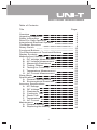
Model UT201/202: OPERATING MANUAL
Table of Contents
Title
Page
Overview
Unpacking Inspection
Safety Information
Rules For Safe Operation
International Electrical Symbols
The Meter Structure
Rotary Switch
Functional Buttons
The Effectiveness of Functional Buttons
Display Symbols
Measurement Operation
A. DC Voltage Measurement
B. AC Voltage Measurement
C. Measuring Resistance
D. Testing Diodes
E. Testing for Continuity
F. Temperature Measurement
G. AC Current Measurement
Sleep Mode
Specifications
A. General Specifications
B. Environmental Restriction
Accuracy Specifications
A. AC Voltage
B. DC Voltage
C. Resistance
D. Continuity Test
E. Diode Test
F. Temperature
G. AC Current
Maintenance
A. General Service
B. Replacing the Battery
1
3
4
5
6
8
9
10
11
12
13
15
15
16
17
19
20
22
23
25
26
26
26
27
27
27
28
28
28
29
29
30
30
30
Model UT201/202: OPERATING MANUAL
2
Model UT201/202: OPERATING MANUAL
Overview
This Operating Manual covers information on safety
and cautions. Please read the relevant information
carefully and observe all the Warnings and Notes strictly.
Warning
To avoid electric shock or personal injury, read the
“Safety Information” and “Rules for Safe Operation”
carefully before using the Meter.
Digital Multimeter Model UT201/202 (hereafter referred
to as “the Meter”) are 3 1/2 digits with steady operations,
fashionable structure and highly reliable measuring
instrument. The Meter uses large scale of integrated circuit
with double integrated A/D converter as its core and has
full range overload protection.
The Meter can measure AC/DC Voltage, AC Current,
Resistance, Temperature( oF/ oC), Diodes, Continuity
and so on.
3
Model UT201/202: OPERATING MANUAL
Unpacking Inspection
Open the package case and take out the Meter. Check
the following items carefully to see any missing or damaged
part:
Item
1
2
3
4
Description
English Operating Manual
Test Lead
Point Contact Temperature Probe
(UT202 only)
1.5V Battery (AAA)
Qty
1 piece
1 pair
1 piece
2 pieces
In the event you find any missing or damage, please
contact your dealer immediately.
4
Model UT201/202: OPERATING MANUAL
Safety Information
This Meter complies with the standards IEC61010: in
pollution degree 2, overvoltage category (CAT. II 600V,
CAT. III 300V) and double insulation.
CAT. II: Local level, appliance, PORTABLE EQUIPMENT
etc., with smaller transient overvoltages than CAT. III.
CAT. III: Distribution level, fixed installation, with smaller
transient overvoltages than CAT. IV
Use the Meter only as specified in this operating manual,
otherwise the protection provided by the Meter may be
impaired.
In this manual, a Warning identifies conditions and
actions that pose hazards to the user, or may damage
the Meter or the equipment under test.
A Note identifies the information that user should pay
attention to.
International electrical symbols used on the Meter and
in this Operating Manual are explained on page 8.
5
Model UT201/202: OPERATING MANUAL
Rules For Safe Operation (1)
Warning
To avoid possible electric shock or personal injury,
and to avoid possible damage to the Meter or to the
equipment under test, adhere to the following rules:
l Before using the Meter inspect the case. Do not
use the Meter if it is damaged or the case (or part
of the case) is removed. Look for cracks or
missing plastic. Pay attention to the insulation
around the connectors.
l Inspect the test leads for damaged insulation
or exposed metal. Check the test leads for
continuity. Replace damaged test leads with
identical model number or electrical specifications
before using the Meter.
l Do not apply more than the rated voltage, as
marked on the Meter, between the terminals or
between any terminal and grounding. If the value
to be measured is unknown, use the maximum
measurement position and reduce the range step
by step until a satisfactory reading is obtained.
l When measurement has been completed, disconnect
the connection between the test leads and the
circuit under test, remove the testing leads away
from the input terminals of the Meter and turn
the Meter power off.
l The rotary switch should be placed in the right
position and no any changeover of range shall
be made during measurement is conducted to
prevent damage of the Meter.
l Do not carry out the measurement when the
Meter’s back case and battery compartment are
not closed to avoid electric shock.
l Do not input higher than 600V between the Meter’s
terminals and the grounding to avoid electric
shock and damages to the Meter.
6
Model UT201/202: OPERATING MANUAL
Rules For Safe Operation (2)
l
l
l
l
l
l
l
l
l
l
l
l
When the Meter working at an effective voltage
over 60V in DC or 30V rms in AC, special care
should be taken for there is danger of electric
shock.
Use the proper terminals, function, and range
for your measurements.
Do not use or store the Meter in an environment
of high temperature, humidity, explosive,
inflammable and strong magnetic field. The
performance of the Meter may deteriorate after
dampened.
When using the test leads, keep your fingers
behind the finger guards.
Disconnect circuit power and discharge all high
-voltage capacitors before testing resistance,
continuity and diode.
Replace the battery as soon as the battery indicator
appears. With a low battery, the Meter might
produce false readings that can lead to electric
shock and personal injury.
When servicing the Meter, use only the same
model number or identical electrical specifications
replacement parts.
The internal circuit of the Meter shall not be altered
at will to avoid damage of the Meter and any
accident.
Soft cloth and mild detergent should be used to
clean the surface of the Meter when servicing.
No abrasive and solvent should be used to
prevent the surface of the Meter from corrosion,
damage and accident.
The Meter is suitable for indoor use.
Turn the Meter off when it is not in use and take
out the battery when not using for a long time.
Constantly check the battery as it may leak when
it has been using for some time, replace the
battery as soon as leaking appears. A leaking
battery will damage the Meter.
7
Model UT201/202: OPERATING MANUAL
International Electrical Symbols
AC (Alternating Current).
DC (Direct Current).
AC or DC.
Grounding.
Double Insulated.
Deficiency of Built-In Battery
Continuity Test.
Diode.
Capacitance Test
Fuse.
Warning. Refer to the Operating Manual.
Conforms to Standards of European Union.
8
Model UT201/202: OPERATING MANUAL
The Meter Structure (see figure 1)
( figure 1)
1.
2.
3.
4.
5.
6.
7.
Input Terminals
LCD Display
Functional Buttons
Rotary Switch
Trigger: press the lever to open the transformer jaws.
When the pressure on the lever is released, the jaws
will close.
Hand Guards: to protect user’s hand from touching
the dangerous area.
Transformer Jaws: designed to pick up the AC current
flowing through the conductor. It could transfer current
to voltage.
9
Model UT201/202: OPERATING MANUAL
Rotary Switch
Below table indicated for information about the rotary switch
positions.
Rotary
Function
Switch
Position
OFF
Power is turned off.
AC/DC voltage measurement.
: Diode test.
: Continuity test.
Ω
o
Ω : Resistance measurement.
o
CF
A
Temperature measurement
(UT202 only)
AC current measurement range from 0.001A
to 400.0A
10
Model UT201/202: OPERATING MANUAL
Functional Buttons(1)
Below table indicated for information about the functional
button operations.
AC
voltage measurement.
l
Press HOLD to enter and exit the
HOLD
Hold mode in any mode, the Meter beeps.
l Press and hold HOLD button
while turning on the Meter to display
full icons.
MAX
Press MAX to start recording and updating
of maximum values.
SELECT Press SELECT button to switch between
o
o
Ω
and C F .
11
Model UT201/202: OPERATING MANUAL
The Effectiveness of Functional Buttons
Not every functional buttons can be used on every rotary
switch positions. Below two tables describe which functional
buttons can be used on which rotary switch positions
Model: UT201
Rotary Switch
Positions
Functional Buttons
SELECT
N/A
V
V
MAX
HOLD
N/A
Ω
N/A
N/A
N/A
2/20A
A
A 200/400A
N/A
N/A
Model: UT202
Rotary Switch
Positions
Functional Buttons
SELECT
N/A
V
V
MAX
N/A
Ω
o
N/A
o
N/A
F C(K-Type)
2/20A
A
A 200/400A
N/A
N/A
12
HOLD
Model UT201/202: OPERATING MANUAL
Display Symbols(1) (see figure 2)
No.
Symbol
1
AC
2
DC
3
4
5
6
7
8
9
MAX
10
Ω,kΩ,MΩ
o
Meaning
Indicator for AC voltage or current
Indicator for DC voltage
The battery is low.
Warning: To avoid false readings,
which could lead to possible electric
shock or personal injury, replace
the battery as soon as the battery
indicator appears.
The Meter is in the auto range mode
in which the Meter automatically selects
the range with the best resolution.
Test of diode.
The continuity buzzer is on.
Maximum reading displayed
Date hold is active.
o
CF
13
Model UT201/202: OPERATING MANUAL
Display Symbols(2) (see figure 2)
No.
Symbol
11
A
mV, V
12
13
14
OL
Meaning
Amperes (amps). The unit of current.
Volts. The unit of voltage.mV: Millivolt.
1x10⁻³ or 0.001 volts
Indicates negative reading
The input value is too large for the
selected range
14
Model UT201/202: OPERATING MANUAL
Measurement Operation(1)
A. DC Voltage Measurement (see figure 3)
red
black
( figure 3)
Warning
To avoid harms to you or damages to the Meter from
eletric shock, do not attempt to measure voltages
higher than 600V AC/DC, although readings may be
obtained.
The DC Voltage ranges are:
200.0mV, 2.000V, 20.00V, 200.0V and 600V.
To measure DC voltage, connect the Meter as follows:
1. Insert the red test lead into the
VΩ terminal
and the black test lead into the COM terminal.
2. Set the rotary switch to V .
3. Connect the test leads across with the object being
measured.
The measured value shows on the display.
Note
l In each range, the Meter has an input impedance of
10MΩ. This loading effect can cause measurement
errors in high impedance circuits. If the circuit impedance
is less than or equal to 10kΩ, the error is negligible
(0.1 or less).
15
Model UT201/202: OPERATING MANUAL
Measurement Operation(2)
l
When DC voltage measurement has been completed,
disconnect the connection between the testing leads
and the circuit under test and remove testing leads
from the input terminals.
B. AC Voltage Measurement (see figure 4)
red
black
( figure 4)
Warning
To avoid harms to you or damages to the Meter from
eletric shock, do not attempt to measure voltages
higher than 600V AC/DC, although readings may be
obtained.
16
Model UT201/202: OPERATING MANUAL
Measurement Operation(3)
Note
l In each range, the Meter has an input impedance of
10MΩ. This loading effect can cause measurement
errors in high impedance circuits. If the circuit impedance
is less than or equal to 10kΩ, the error is negligible
(0.1 or less).
l When AC voltage measurement has been completed,
disconnect the connection between the testing leads
and the circuit under test and remove testing leads
from the input terminals.
C.Measuring Resistance (see figure 5)
red
black
( figure 5)
Warning
To avoid harms to you, do not attempt to input voltages
higher than 60V DC or 30V rms AC.
To avoid damages to the Meter or to the devices
under test, disconnect circuit power and discharge
all the high-voltage capacitors before measuring
resistance.
17
Model UT201/202: OPERATING MANUAL
Measurement Operation(5)
D.Testing Diodes (see figure 6)
red
black
( figure 6)
Warning
To avoid damages to the Meter or to the devices under
test, disconnect circuit power and discharge all the
high-voltage capacitors before testing diodes.
Use the diode test to check diodes, transistors, and other
semiconductor devices. The diode test sends a current
through the semicondutor junction, then measure the
voltage drop across the junction. A good silicon junction
drops between 0.5V and 0.8V.
To test the diode out of a circuit, connect the Meter as
follows:
1. Insert the red test lead into the
VΩ terminal and
the black test lead into the COM terminal.
2. Set the rotary switch toΩ
and press SELECT
button to select
measurement mode.
3. For forward voltage drop readings on any semiconductor
component, place the red test lead on the component’s
anode and place the black test lead on the component’s
cathode.
19
Model UT201/202: OPERATING MANUAL
Measurement Operation(6)
Note
l In a circuit, a good diode should still produce a forward
voltage drop reading of 0.5V to 0.8; however, the
reverse voltage drop reading can vary depending
on the resistance of other pathways between the
probe tips.
l Connect the test leads to the proper terminals as
said above to avoid error display.
l The LCD will display OL indicating either open circuit
or wrong polarity connection.
l The unit of diode is volt (V), displaying the forward
voltage drop readings.
l To remove the objects being tested from the circuit
when measuring can obtain a more accurate result.
l When diode testing has been completed, disconnect
the connection between the testing leads and the
circuit under test and remove testing leads from the
input terminals.
E.Testing for Continuity (see figure 7)
red
( figure 7)
20
black
Model UT201/202: OPERATING MANUAL
Measurement Operation(7)
Warning
To avoid damages to the Meter or to the devices under
test, disconnect circuit power and discharge all the
high-voltage capacitors before measuring continuity.
To test for continuity, connect the Meter as follows:
1. Insert the red test lead into the
VΩ terminal and
the black test lead into the COM terminal.
2. Set the rotary switch to Ω
and press SELECT
button to select measurement mode.
3. The buzzer sounds if the resistance of a circuit under
test is less than 50 Ω .
4. The buzzer may or may not sounds if the resistance
of a circuit under test is between 50 Ω to 120 Ω .
5. The buzzer does not sound if the resistance of a circuit
under test is higher than 120Ω.
Note
l The buzzer beeps once when pressing any buttons
at any rotary switch positions except at 2/20A positions
if the button is valid. If the button is not valid, it does
not beep. At 2/20A rotary switch position, the buzzer
is set not to beep.
l The buzzer beeps 5 times continuously on around
1 minute before entering the sleep mode. When it
is just before entering the sleep mode, it will have
one long beep to warn you.
l The LCD displays OL indicating the circuit being
tested is open.
l When continuity testing has been completed, disconnect
the connection between the testing leads and the
circuit under test and remove testing leads from the
input terminals.
21
Model UT201/202: OPERATING MANUAL
Measurement Operation(8)
F. Temperature Measurement (UT202 Only)
(see figure 8)
red
black
( figure 8)
o
o
The temperature measurement ranges are -40 C~1000 C
o
o
and -40 F~1832 F.
To measure temperature, connect the Meter as follows:
1. Insert the red temperature probe into the
VΩ
terminal and the black temperature probe into the COM
terminal.
o o
2. Set the rotary switch to F C and press SELECT button
o
o
o
to select F or C measurement mode. C measurement
mode is default.
3. Place the temperature probe to the object being measured.
The measured value shows on the display.
Note
l The Meter automatically displays the temperature
value inside the Meter when there is no temperature
probe connection.
l When temperature measurement has been completed,
disconnect the connection between the temperature
probe and the circuit under test, and remove the
temperature probe away from the input terminals of
the Meter.
22
Model UT201/202: OPERATING MANUAL
Measurement Operation(9)
G. AC Current Measurement (see figure 9)
( figure 9)
Warning
To avoid electric shock, never measure current while
the test leads are inserted into the input terminals
and disconnect test leads and tested circuit connection.
Never attempt an in-circuit current measuremnet
where the open-circuit voltage between the circuit
and the ground is greater than 600V
Use proper function and range for the measurement.
The measuremnet ranges of current are: 2.000A, 20.00A,
200.0A and 400A.
To measure current, do the following:
1. Set the rotary switch to 2/20A or 200/400 A
2. Press the lever to open the transformer jaws.
3. Center the conductor within the transformer jaw.
The measured value shows on the display, it is a
effective value of sine wave (mean value response).
23
Model UT201/202: OPERATING MANUAL
Measurement Operation(10)
Note:
l To obtain accurate reading, measure only one
conductor at each time.
l When current measurement has been completed,
disconnect the connection between the conductor
under test and the jaw, and remove the conductor
away from the transformer jaw of the Meter.
24
Model UT201/202: OPERATING MANUAL
Copyright 2001 Uni-Trend International Limited.
All rights reserved.
Manufacturer:
Uni-Trend International Limited
Rm901, 9/F, Nanyang Plaza
57 Hung To Road
Kwun Tong
Kowloon, Hong Kong
Tel: (852) 2950 9168
Fax: (852) 2950 9303
Email: [email protected]
http://www.uni-trend.com
32