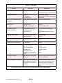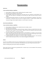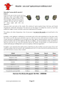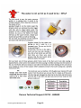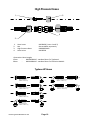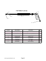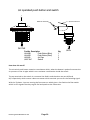
1
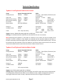
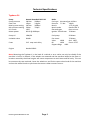
DEMON TYPHOON 2
PRESSURE WASHER
OPERATOR MANUAL
Clemas & Co. Unit 5 Ashchurch Business Centre, Alexandra Way, Tewkesbury,
Gloucestershire, GL20 8NB.
Tel: 01684 850777
Fax: 01684 850707
Email: [email protected]
Web: www.clemas.co.uk
DEMON TYPHOON D1
AIR COOLED
PRESSURE WASHER
OPERATOR MANUAL
Clemas & Co. Unit 5 Ashchurch Business Centre, Alexandra Way, Tewkesbury,
Gloucestershire, GL20 8NB.
Tel: 01684 850777
Fax: 01684 850707
Email: [email protected]
Web: www.clemas.co.uk
DEMON TYPHOON RANGE Typhoon D1 Typhoon 2 Typhoon P4 Typhoon Evolution Air Cooled Typhoon Evolution Water Cooled A Declaration of Conformity (E.H.S.R.) We, Demon International Limited of Abbots Close, Lee Mill Industrial Estate, Ivybridge, Devon PL21 9GA declare that this machine must be operated in accordance with the operation and safety instructions as supplied with this machine. This machine is manufactured in accordance with the following standards and recommendations. HSE PVB PM29 – BS5415 Part 1 – BS5415 Section 2.4 1986 This instruction manual is relevant only to the following machine and will not be kept updated unless specifically requested by the customer. However, any changes to the operating procedure or changes which might affect the safety of this machine will be notified to the registered owner of this machine only. Machine Type Serial Number Voltage Working Pressure Date of Supply Demon Typhoon Manual Issue 1/07
Page 1
Technical Specifications Typhoon 1 and Typhoon Evolution Air Cooled Pump Annovi Reverberi RK15.20 Boiler Pump pressure 200 bar 2900psi Fuel type Gas oil/derv /kerosene (not on Evolution) Flow rate 15lpm 3.3gpm Pressure 7.5 bar 110psi Max by‐pass setting 205 bar 3000psi Nozzle 1.75 US galls Min pressure setting 50 bar 750psi Nozzle make Danfoss 60° S 1505 Electrode gap 6mm ± 1mm H.P nozzle Motor power 8.2HP @ 3000rpm Ignition Transformer 70 Watts Pump oil 10W/40 Fuel pump 50 Watts Unloader valve GM3A Fan motor 75 Watts Valve 1828 Seal 1857 Fuses 3.15 amp semi delay Oil 1856 Piston 2757 Support Rings 1829 Engine: Yanmar L100AE‐DE producing 8.2HP at 3000 rpm Cooling: Air cooled (Evolution model has an extraction fan for hot air removal) Note: Mounting the Typhoon 1 in the back of a vehicle or on a trailer can only be reliable if the machine is left on its wheels. If the wheels are removed and the machine bolted to the floor vi‐
brations caused by the diesel engine will cause component to work loose and fail early. This can be overcome by two methods, leave the wheels on and fix the castor wheel end of the machine and use the wheel chocks or purchase the correct rubber mounts from us. Typhoon 2 and Typhoon Evolution Water Cooled Pump Annovi Reverberi RK15.20 Boiler Pump pressure 200 bar 2900psi Fuel type Gas oil/derv /kerosene (not on Evolution) Flow rate 151pm 3.3gpm Pressure 7.5 bar 110psi Max by‐pass setting 205 bar 3000psi Nozzle 1.75 US galls Min pressure setting 50 bar 500psi Nozzle make Danfoss 60° S 1505 Electrode gap 6mm ± 1mm H.P nozzle Motor power 8.3HP @ 2200rpm Ignition Transformer 70 Watts Pump oil 10W/40 Fuel pump 50 Watts Unloader valve GM3A Fan motor 75 Watts Fuses 3.15 amp semi delay Engine: Isuzu 2CA1 producing 8.3HP at 2100rpm Cooling: Water cooled engine using heat exchanger to transfer engine heat to the pumped water increasing boiler efficiency. Low water cut out separate to the engine management system to stop engine before the tank is empty. Separate extraction fan for engine compartment. Demon Typhoon Manual Issue 1/07
Page 2
Technical Specifications Typhoon P4 Pump Annovi Reverberi RK15.20 Boiler Pump pressure 200 bar 2900psi Fuel type Kerosene/gas oil/derv Flow rate 15lpm 3.3gpm Pressure 7.5 bar 110psi Max by‐pass setting 205 bar 3000psi Nozzle 1.75 US galls Min pressure setting 50 bar 750psi Nozzle make Danfoss 60° S H.P nozzle 1505 Electrode gap 6mm ± 1mm Motor power 8.2HP @ 3000rpm Ignition Transformer 70 Watts Pump oil 10W/40 Fuel pump 50 Watts Unloader valve GM3A Fan motor 75 Watts Valve 1828 Seal 1857 Fuses 3.15 amp semi delay Oil 1856 Piston 2757 Support Rings 1829 Engine Honda GX340 Note: Mounting the Typhoon 1 in the back of a vehicle or on a trailer can only be reliable if the machine is left on its wheels. If the wheels are removed and the machine bolted to the floor vi‐
brations caused by the diesel engine will cause component to work loose and fail early. This can be overcome by two methods, leave the wheels on and fix the castor wheel end of the machine and use the wheel chocks or purchase the correct rubber mounts from us. Demon Typhoon Manual Issue 1/07
Page 3
FAULT FINDER FAULT CAUSE REMEDY Boiler will not work Blown Fuse Check power to electrical enclo‐
sure and 3.15 amp control fuses. Sudden pressure loss No water No Chemical Burst disc blown Check water supply Check chemical drum, close valve. Replace Disc Water turns to steam during normal use Partially blocked H.P.Nozzle. Clean and flush machine Low pressure HP Nozzle worn Unloader set wrongly Replace Reset unloader valve Low pressure with Noise & vibration Valves worn or blocked Piston seals worn Pump sucking air Clean or replace as required Replace Check chemical valve and inlet pipe Pump will not By‐pass Jammed non‐return valve O Ring damaged Clear blockage Replace Water drips from pump bot‐
tom Piston seals worn Replace Oil drips from pump bottom Oil seals worn Replace Burner will not ignite Fuel tank empty Fuel filter blocked Fuel nozzle blocked Electrodes dirty Out of adjustment Flow switch out of adjust‐
ment Refill Replace Clean or replace Clean or replace Reset Adjust Oil is milky in colour Water ingress through oil filler plug Drain oil, rinse out with clean par‐
affin the replace oil Flames coming out of chimney Poor quality fuel leading to poor combustion and then burning off of excess fuel in the boiler. Maintain the fuel system more often, drain the sediment out of the tank regularly and clean or replace filters and nozzles more often. If in doubt ask—our advice is free and can save you money Demon Typhoon Manual Issue 1/07
Page 4
Environmental Statement ‐ these machines have been designed to be re‐
cycled and wherever possible recyclable components have been used. The design of these machines ensures that they can be economically upgraded and kept in service for longer periods of time resulting in the minimum amount of waste to be disposed of. Keep your machine maintained and regularly serviced to make sure your impact by using this machine on the environment is minimised PREPARATION a. Connect hose to water inlet connector and turn on. b. Connect high pressure hose to connector. (Evolution models are permanently con nected.) c. Connect lance to hose. d. Top up fuel levels and check oil levels in pump and engine. e. If chemical is to be used place filter in drum of chemical and open valve. If not make sure valve is closed. OPERATION TO START MACHINE a. b. c. d. e. Turn Ignition Switch until the light comes on. Turn key to glow plug position until the light goes out (Isuzu engine only) turn key to cranking position and the engine will start. Hold trigger closed until pressure is reached. Check voltage with trigger pulled =110v +‐ 5% Push red switch once, or burner switch to the on position, (Evolution models) burner will then operate. Burner will now ignite when trigger is pulled. Demon Typhoon Manual Issue 1/07
Page 5
OPERATION TO STOP MACHINE a. b. c. d. Switch to cold by pressing Red button once or turn burner switch off, run the ma
chine until the water turns cold. Turn ignition switch off and engine will stop. Pull trigger to release excess pressure and disconnect from machine. If the machine is to be stored, drain water system. Top up fuel levels ( Boiler & Engine ) Check oil levels ( Pump & Engine ) Place Typhoon cover over machine. Evolution models ‐ drain water tanks IF IN DOUBT ASK ‐ OUR ADVICE IS FREE Royal Navy special instructions ‐ use at sea Storage of the Typhoon Pressure Washer 1. Ensure machine is stored in a dry environment. Ensure the cover is placed on the machine. Ensure all Saltwater has been rinsed off machine with low pressure water. DO NOT STORE THIS PRESSURE WASHER OUTSIDE OF THE SHIP. LEAVING THE UNIT OUTSIDE OF THE SHIP WILL CAUSE SALTWATER DAMAGE. Demon Typhoon Manual Issue 1/07
Page 6
MINIMUM SERVICE SCHEDULES DAILY CHECK THE FOLLOWING a. Oil level ‐ top up as required. b. Fuel tank ‐ top up as required. c. All hose unions for leaks. d. Hose condition ‐ cuts etc. Engine Service ‐ Refer to Yanmar or Isuzu service intervals in manual supplied with Typhoon. EVERY 500 HOURS OR SIX MONTHS (WHICHEVER COMES FIRST) a. b. c. d. e. f. g. h. i. Drain and replace pump oil. MINIMUM SERVICE SCHEDULES Drain and refill fuel tank. Clean and reset electrodes. Replace fuel filter. Clean water filter. Replace high pressure nozzle. Replace fuel nozzle. Descale water system. (hard water areas only) Note: in extreme hard water areas it may be necessary to fit a limefighter device which is a ceramic magnetic tube that ionises the calcium carbonate allowing them to pass through the pressure washer and not form deposits inside. EVERY 1000 HOURS OR 12 MONTHS (WHICHEVER COMES FIRST) a. b. c. d. e. f. g. h. i. Complete 500 hour service. Replace pump seals. Replace oil seals. Check float level. Replace chemical pipes. Check unloading pressure and safety valve pressure and adjust. Replace fuel nozzle and set fuel pressure. Check flow switch and adjust if necessary. Check electrical connections for tightness. The above service schedules are intended as a guide only, actual service times and replacements parts required will vary according to the area and the usage of the machine. Demon Typhoon Manual Issue 1/07
Page 7
Safety Instructions Water at high pressure is dangerous and can cause serious injury. This machine is to be used with great caution. Operating Instructions a. NEVER point the high pressure spray jet at any person, animal, glass or any other material which may shatter. b. PREVENT any over‐spray from injuring other people or damaging property. c. DO NOT even try to use a pressure washer on machinery or electrical equipment that is connected in any way to the mains supply. (all switches in the off position, pull out all plugs and if possible remove fuses). Cover or seal electric motors and fittings to prevent entry of water. d. ALWAYS when using machine:‐ ‐ wear safety goggles and helmet or helmet with a visor. ‐ wear waterproof clothing and gloves. ‐ take particular care with detergents and chemicals. e. NEVER attempt to disconnect any hose with pressure in it or allow the hose to be flattened or kinked. f. DO NOT use a high pressure hose from a ladder. Use a platform tower or proper scaffolding. g. CHECK voltage output is between 105V and 115V if not check engine speed or call our service department for advice. h. ALWAYS disconnect the hoses when the machine is not in operation and protect the ma
chine from frost and cold winds. i. ALWAYS use the machine in a well ventilated area. CAUTION ‐ if using chemicals some brands will adversely affect the brass components fitted to this machine. If in doubt please telephone our technical department for advice. Environmental Advice ‐ use the least aggressive or least caustic products that will achieve the cleaning result. Demon Typhoon Manual Issue 1/07
Page 8
Typhoon Arrangement Drawings
H6442R Boiler Control Button
YAN114351-77500
Key Switch
DEM10341
Electrical Enclosure
Water Inlet
MTM73001Coupling
MTM73020 Stepped
Nipple
DEM10435
Water Tank
MTM25801
Chemical Valve
DEM10410
Boiler Fuel Tank
MTM70013 Water Outlet
Engine Fuel Tank
DB001000
Boiler
Air Filter
MV00380
Flow Switch
MTR00910
Alternator
ARXR1520
Pump
ARGM3A
Unloader Valve
Demon Typhoon Manual Issue 1/07
Page 9
Typhoon Evolution General Arrangement Position of Drain holes Important information Caution—towing these machines at speed with the water tanks full over rough ground or speed bumps is not advised as this places excessive stress on the machine which may lead to damage. Demon Typhoon Manual Issue 1/07
Page 10
Typhoon Evolution Arrangement Drawings Inspection Cover Xenon Beacon Ventilation fan outlet—Hot air outlet— do not obstruct Gas Strut TYP0007 Gas Strut TYP0007 Pump ARXR 15.20 RK15.20 Retractable hose reel (30m No hose) MTM20009 Demon Typhoon Manual Issue 1/07
Heat Exchanger— water cooled model only Page 11
Alternator Belt GAT0030 Typhoon 1 Belt GAT0032 Typhoon 2 Typhoon Evolution Arrangement Drawings Gas Strut TYP0007 Engine controls Gas Strut TYP0007 Electrical enclosure Fuel level gauge DEM202551 Low water cut‐out Fuel tank (45 litres) DEM10415 Engine Management System Fuel filler cap DEM10423 Tachometer Keyswitch Demon Typhoon Manual Issue 1/07
Page 12
WARRANTY This warranty covers the cost of all replacement parts and labour charges incurred. It does not cover the cost of transport or carriage. It is the owners responsibility to return the machine to a service depot or pay the travelling expenses of a service engineer to attend. Demon International’s decision in warranty matters is final and binding. Demon International Ltd undertake to repair or replace, any component which may fail due to a manufac‐
turing fault within a period of 12 months from the date of purchase, provided that any fault or damage was not sustained by; A. Lack of regular and proper maintenance, user negligence, misuse, or damage caused by ice and frost. B. The effects of contaminated fuel or water, the use of non‐approved chemicals or an insufficient or unsuitable electrical supply. C. The effects of un‐authorised modification and use. D. Compression damage to high pressure hose. (HOSES WARRANTED FOR 1 MONTH ONLY) E. Worn out items considered fair wear and tear. Parts which may or may not wear out during the first year and which are considered service items which will need replacing from time to time: High pressure nozzle, lance, trigger, hoses, fuel nozzle, fuel filter, pis‐
ton seals, valves, unloader seats and seals, water filter, non‐return valve, chemical barbs, chemical pipes and pump oil seals. It is the owners responsibility to ensure the Pressure Washer is kept in a safe and suitable environment and any faults reported by operatives to be rectified at the earliest possible date. It is the operators responsibility to check the Pressure Washer for any faults and report them immediately. The Pressure Washer must be used in accordance with the manufacturers specifications and guidelines. Demon International Ltd undertake to use the highest quality components available during manufacture, but cannot be held responsible for any undue consequence arising from the use of there Pressure Washer. This warranty is given to the original purchaser only and is not transferable without the fully authorised and written consent of Demon International Ltd. Demon Typhoon Manual Issue 1/07
Page 13
Warranty Procedure End Users If your machine develops a problem: 1. Phone Demon for advice with the model and serial number to hand. 2. Describe fully the problem as best you can. 3. If the problem cannot be resolved over the phone then the machine can be booked in for repair and if the faults are covered by the warranty the repair will be carried out free of charge. 4. If you cannot bring the machine in for repair then we will despatch an engineer. If the fault is covered by the warranty then we will not charge for labour or spares used, however the transport charge will be payable weather or not the repair is warranty. Hire Centres and Dealers If your machine develops a problem: 1. Phone Demon for advice with the model and serial number to hand. 2. Describe fully the problem. 3. We will advise you on the best course of action, however if parts are required you must raise a purchase order number to cover the parts. When the parts are fitted they must be returned for examination before a credit note is issued. 4. If you are unable to repair the machine then we will despatch an engineer to carry out the repair. We will need a purchase order to cover the cost of transport to and from the site and for parts and labour if the repair is not covered under the warranty. 5. If required Demon will arrange for a carrier to collect a damaged machine, if the warranty claim is valid we will pay this cost, if not it will be charged to the customer. Notes: You will not invalidate the warranty by investigating faults and repairing them yourself providing you follow our advice. Hire Centres and Dealers are expected to carry out all repairs themselves with Demon crediting faulty parts upon receipt and inspection. Spare parts fitted to machines are guaranteed for 1 month only or the remainder of the warranty period whichever is longer. Demon Typhoon Manual Issue 1/07
Page 14
Demon Typhoon Manual Issue 1/07
Page 15
Demon Typhoon Manual Issue 1/07
Page 16
Demon Typhoon Manual Issue 1/07
Page 17
High Pressure Hoses
1
2
4
3
1. 2. 3. 4. Hose Insert Nut High Pressure Hose Hose Joiner MV00490 ( items 1 and 2) Not available separately HH00030MVG MV00500 Alternative Hose Lengths 15mtr ‐ HH00050MVG ‐ standard hose for Typhoon 1 30mtr ‐ HH00100MVG ‐ standard hose for Evolution Models Typhoon HP Hoses
Typhoon 1 with Trailer Kit
Outlet to Hose Reel
HH00024 - 965mm long
Typhoon Evolution Burst Disc to Hose Reel
HH00015 - 1350mm long
Typhoon - All Models
Unloader Valve to Flow Switch
HH00025 - 560mm Long
Typhoon Evolution - Flow Switch to Boiler
HH00016 - 1000mm long
Typhoon 1
Boiler to Burst Disc
HH00026 - 420mm Long
Typhoon 1
Flow Switch to Boiler
HH00027 - 230mm Long
Demon Typhoon Manual Issue 1/07
Page 18
Hot Water Lances
5
2
3
4
1
6
Position Part Number Description Qty 1 N26001/1505 High Pressure Nozzle 1 2 DEM20340 Barrel Nut 1/4” BSP 1 3 MTM0001000 Rubber Cover 1 4 DEM10032R QR Lance 05 1 5 DEM10030 QR Trigger 1 6 MTM70012 MVG Coupling 1 Demon Typhoon Manual Issue 1/07
Page 19
Air operated push button and switch
Common Terminal
NO & NC Terminals
Air Out
Part No. Description
H6442B
Push Button (Blue)
H6442R
Push Button (Red)
H65000
Air Pipe
H6871AC
Switch
Qty
1
1
2
2
Air In
How does this work? The air switch push button contains a membrane which, when the button is pushed increases the air pressure in the air pipe which in turn activates a mechanism inside the switch. The top terminal on the switch is a common live feed in and the other two are N/O and N/C respectively which means it does not matter which terminal you use for the switching signal. With the Typhoon 1 you are turning the fan motor on which gives a live feed to the flow switch which in turn signals the relay to give fuel and sparks at the same time. Demon Typhoon Manual Issue 1/07
Page 20
Typhoon Wiring Diagram
0V
0
150
115V
V
Air Switch
1
5
Relay 1 Coil
Fuse 1 - 3.15A
4
3
Relay 1
Fan Motor
Fuse 2 - 3.15A
4
3
Relay 2
Ignition Transformer
Fuel Pump
Relay 2 Coil
5
1
Flow Switch
Chemical Solenoid Valve
Description Part Number Qty Airswitch H6871AC 1 Relay DEM100915 2 Fuse FUSE002 2 Fan Motor DB000171 1 Ignition transformer DB000255 1 Fuel Pump DB002305 1 Flow Switch MV00385 1 Chemical Solenoid Valve DEM101191 1 Volt Meter 150V DEM101107 1 Demon Typhoon Manual Issue 1/07
Page 21
M
Typhoon Electric Box
3
Air Switch
4
4
2
2
3
3
9
NC unused terminal
7
Ignition Transformer
5
5
1
1
4
6
5
8
9
11
10
Pos Description Part No Qty 3 Relay Base DEM4100750 2 4 Relay DEM100915 2 5 Fuse Holder DEM100920 2 6 3 Way Connector DEM100948 1 7 Fuse 3.15 amp FUSE002 2 8 Typhoon Electrical Box DEM100875 1 9 PG 9 Cable Gland DEM20110 6 10 PG11 Cable Gland DEM20100 2 11 Back Plate Electrical Box DEM10330 1 Not Shown End Stops—fitted to the rail to prevent the fuse holders and relays from detaching. DEM100921 2 Demon Typhoon Manual Issue 1/07
Page 22
Typhoon Evolution Wiring Diagram
0V
0
150
115V
3.15 A
Fuse
V
Rotary Switch
1
5
Relay 1 Coil
Fuse 1 - 3.15A
4
3
Relay 1
Fan Motor
Fuse 2 - 3.15A
4
3
Relay 2
M
Ignition Transformer
Fuel Pump
Relay 2 Coil
1
5
Flow Switch
Chemical Solenoid Valve
M
Extractor Fan
Fuse 3.15amp FUSE002 Rotary Switch DEM100755 Relay DEM100915 Fan Motor DB000171 Ignition Transformer DB000255 Fuel Pump DB002305 Flow Switch MV00385 Chemical Solenoid Valve DEM101191 Extractor Fan DEM100918 Demon Typhoon Manual Issue 1/07
Page 23
Typhoon Evolution Electric Box
3
4
4
2
2
3
3
9
NC unused terminal
7
Ignition Transformer
5
5
1
1
4
6
5
8
9
11
10
3 Relay Base DEM100750 4 Relay DEM100915 5 Fuse Holder DEM100920 6 3 Way Connector Block DEM100920 7 Fuse 3.15amp FUSE002 8 Electrical Box DEM10323 9 PG 9 Cable Gland DEM20110 10 P G 11 Cable Gland DEM20100 11 Back Plate Electrical Box DEM10330 Not Shown End Stops—fitted to the rail to prevent the fuse holders and relays from detaching DEM100921 Demon Typhoon Manual Issue 1/07
Page 24
Inner Boiler Details
1
2
3
23
4
5
6
7
8
9
10
25
11
12
24
13
14
15
16
17
18
19
20
21
22
Demon Typhoon Manual Issue 1/07
Page 25
Outer Boiler Details
26
27
28
29
31
32
30
33
34
35
Demon Typhoon Manual Issue 1/07
36
Page 26
Boiler Parts List No Description Part Number Qty 1 Electrode DB000110 2 2 Adaptor DB000130 1 3 Screw NBW00450 3 4 Top Plate DB000030 1 5 Nozzle Holder DB000020 1 6 Nozzle DB000015 1 7 3/8” BSP Nut DB000340 4 8 Washer DB000320 2 9 Nyloc Nut NBW00160 4 10 Outer Drum Lid DB000041 1 11 Plain Nut NBW00200 4 12 Washer NBW00300 4 13 Spacer DB000280 4 14 Inner Drum Lid & Cone DB000051 1 15 Heating Coil DB000094 1 16 Inner Drum DB000070 1 17 Flame Pan DB000081 1 18 Bolt DB000065 3 19 Washer NBW00310 3 20 Nut DB000345 3 21 Spacer DB000350 3 22 Nut DB000345 3 23 Screw NBW00460 3 24 Flame Swirler DB000100 1 25 Washer NBW00300 9 26 Fuel Pipe DB002400 1 27 HT Cap ( Rubber) DB000220 2 28 Rajah Clip DB000230 2 29 HT Lead DB000215 2 30 Ignition Transformer 230V DB000252 1 Ignition Transformer 110V DB000255 1 31 Gasket DB000300 1 32 Outer Drum + Fan Housing DB000060 1 33 Impeller DB000180 1 34 Fan Motor 230V DB000160 1 Fan Motor 110V DB000170 1 35 Bolt NBW00060 2 36 Washer NBW00280 2 Demon Typhoon Manual Issue 1/07
Page 27
Electrode Setting Details
The electrodes should be set according to the picture. 50% of the ceramic
insulation should be inside the boiler and 50% outside. The electrode gap
should be approximately 6mm and the tips shold not be in the fuel spray.
Common problems - fuels filters and nozzles are not changed regularly enough.
The nozzle is a precision instrument that can be damaged by small particles of
solid matter in the fuel that it is not possible to filter out. Nozzles will not atomise
the fuel correctly leading to a longer flame path which you can see by flames
visible near the top of the chimney. To remedy this empty the fuel tank and fill
with clean fuel, change the filter and then change the fuel nozzle. Clean the
electrodes and grind the tips to reveal new metal. Reset and refit and run the
boiler with the gun removed for 10 minutes. This will burn off any excess fuel
and clean the boiler tubes.
Service the boiler frequently for reliable running, an unserviced boiler does not
heat the water correctly wasting your money!!
Demon Typhoon Manual Issue 1/07
Page 28
Typhoon Chemical and Water Circuits
4
19
8
3
2
6
7
5
1
9
18
To Pump
20
16
17
10
14
15
12
11
13
Chemical & Water Circuits 1 MTM86010 Chemical Filter 1 12 MTM0012FF03 Brass Elbow 1 2 DEM20500 O Clip 4 13 HH0053 Pipe 1 3 DEM10115 Chemical Pipe 2 14 DEM10310 Hose Tail 1 4 DEM101191 Chemical Solenoid 1 15 DEM10300 Hose Tail 1 5 PA00100 Chemical Intake 1 16 MTM0012FF02 Brass Elbow 1 6 MTM71167 Hose Barb Comp 1 17 DEM20255 Adaptor 1 7 DEM20500 Jubilee Clip 4 18 MTM0012FM03 Brass Elbow 2 8 DEM20400 Hose tail 1 19 DEM101191 Chemical Solenoid Valve 1 9 HH0053 Inlet Pipe 1 20 MTM89011B Mesh Insert 1 10 MTM85002 Water Filter 1 21 MTM89011 Brass Filter 1 11 DEM10435 Water Tank 1 Burst Disc Assembly - DEM20230
Graph showing burst pressure
varying with temperature
4500psi /300bar
Burst Disc - DEM20220
Burst Limit
3000psi / 200bar
The burst disc fitted to the Demon hot water range of machines
is designed to burst either with excess heat or excess pressure.
The burst disc works like a fuse and will always fail safe.
Ruptuing of the burst disc is commonly due to one of three faults,
not cooling the machine after using, a poorly maintained boiler
or flow switch failure.
1500psi / 100bar
20°C
Running the machine for two minutes with the boiler
switched off will increase the life of the boiler.
Maintaining the boiler regularly will also
lead to incresed efficiency and fewer breakdowns.
Demon Typhoon Manual Issue 1/07
Page 29
125°C
150°C
Safe Working Limit
Flow Switch - MV00380
Water Flow
Electric Cable
Brass Tube Containing
Bi-Metallic Reed Switch
MV00390
How does it work?
Water from the pump pushes the magnet up
and the bi-metallic switch inside the brass
tube is activated, which in turn signals a relay
in the electrical enclosure to switch the
ignition transformer and fuel pump on
which, in turn, lights the boiler.
When the trigger is closed water stops flowing
and the magnet falls down in the tube switch the
boiler off.
Magnet
Brass Body
Demon Typhoon Manual Issue 1/07
Page 30
Demon Typhoon 1 Fuel Tank
2
Typhoon 1 fuel system
4
6
10
11
7
5
8
To Fuel Pump
12
3
9
1
Fuel System Part List No Part No Description Qty 1 DEM10410 Fuel Tank 24 Litre 1 2 DEM10420 Fuel Tank Cap 1 3 DEM20450 Fuel Pickup Pipe 1 4 DEM20440 Elbow Adaptor 1 5 DEM20452 Nylon Hose Connector 2 6 DEM20450 Fuel Pickup Pipe 1 7 DEM20430 Bulkhead Adaptor 1 8 DEM20440 Elbow Adaptor 1 9 MTM87100 Fuel Filter 1 10 DEM20330 11 DB0023055 Bracket 1 12 DEM20340 1/4” Barrel Nut 1 Demon Typhoon Manual Issue 1/07
1/4” Male x Male Adaptor Page 31
1 4
Typhoon Evo fuel system
5
7
6
2
10
11
5
8
To Fuel Pump
13
12
3
9
1
Typhoon Evolution Fuel System Pos Description Part Number Qty 1 45 Litre Painted Fuel Tank DEM10415 1 2 Locking Fuel Cap DEM10423 1 3 Fuel Pickup Pipe DEM20450 1 4 Fuel Pickup Elbow Adaptor DEM20440 1 5 Fuel Pipe Adaptor DEM20452 2 6 Fuel Pipe DEM20450 1 7 Bulkhead Adaptor DEM20430 3 8 Fuel Pickup Elbow Adaptor DEM20440 1 9 Fuel Filter MTM87100 1 10 1/4” Male x Male Adaptor DEM20330 1 11 Fuel Filter Bracket DB0023055 1 12 1/4” Barrel Nut DEM20340 1 13 Fuel Level Gauge DEM202551 1 Float Valve Assembly
Plastic Nut
Water Outlet
Cap
Piston
Cap Retaining Nut
Arm
Brass Body
Washer
Part No.
DEM10450
DEM10445
DEM10446
DEM10447
Insert
Description
Float Valve Complete
HP Insert (white) 7 to 20bar
MP Insert (black) 3 to 7 bar
LP Insert (green) 0 to 3 bar
Qty
1
1
1
1
No other parts available
Demon Typhoon Manual Issue 1/07
Page 32
Diaphragm
Float
Fuel Pump Assembly
1
2
3
5
4
6
Pressure Adjuster
Item
1
2
3
4
5
6
Description
Fuel Pressure Gauge
Tee
Adaptor
Adaptor
Fuel Pump Complete 110V
Fuel Pump Complete 230V
Screw
Part Number
DEM20630
DB000155
DB000135
DB000145
DB002305
DB002300
AR1260470
Quantity
1
1
1
1
1
1
2
Note: Pump available in 230V or 110V only, fuel pump has no sevicable
parts, when fitting new pump do not shorten leads, pressure set to 110psi (7.5 bar).
Demon Typhoon Manual Issue 1/07
Page 33
Demon Typhoon Manual Issue 1/07
Page 34
GYMATIC 3/A Pos Part Number Description 1 AR1560580 Knob plug 2 AR180030 Screw 3 AR1660210 Nut 4 AR1560400 Handle 5 AR1080070 Pin 6 AR1560420 Adjusting screw 7 AR1560410 Spring guide 8 AR1560440 Plate 9 AR1560350 Spring 10 AR1080610 Spring plate 11 AR1080660 Pin 12 AR1080540 Upper piston 16 AR1560100 Jet 17 AR1560140 Spring 19 AR880581 Plug 20 AR820510 O ring 21 AR1560020 Valve housing 25 AR1560320 Lower piston 27 AR1080831 By pass adjuster 29 AR1560510 Nut 30 AR1560500 Fitting 3/8 30 AR1560530 Fitting 3/8 30 AR1560540 Fitting 3/8 31 AR1560520 Spring 32 AR1250280 Ball 34 AR1560490 Hose tail 35 AR1560110 Adaptor 3/8 35 AR1560111 Adaptor 3/8 36 AR1560650 Hose tail 37 AR800560 O ring 38 AR480560 O ring 39 AR1560670 Detergent reg knob 40 AR1560660 Ring 41 AR1080390 Nut 13,14,15,18,22,23,26,3
3,42 ARKIT2611 O Rings Demon Typhoon Manual Issue 1/07
Page 35
Demon Typhoon Manual Issue 1/07
Page 36
RK MODEL: 15.20H Pos Part No Description Qty Pos Part No Description Qty 1 AR960160 O Ring 6 36 AR1343510 Screw 6 2 AR960090 Plug 6 40 AR1380120 0.10mm shim 1÷3 2 AR1380740 Plug 6 40 AR1380130 0.20mm shim 1÷3 3 AR1389051 Complete Valve 6 40 AR1380530 0.25mm shim 1÷3 4 AR880830 O Ring 6 40 AR1382810 0.05mm shim 1÷3 5 AR880581 Plug 2 42 AR740290 O ring 3 /8 G plug 2 Screw 4 Base 2 6 AR820510 O Ring 2 43 AR1980740 11 AR960110 Support Ring 3 44 AR1260470 12 AR880320 Gasket 3 45 AR1380141 13 AR1380090 Piston Guide 3 46 3
AR1980740 3
/8 G Plug 1 1 14 AR961240 O Ring 3 46 AR1981180 3/
8 G Plug 15 AR880330 Gasket 3 47 AR180101 O Ring 1 16 AR138130 Seal 3 48 AR820361 Plug 1 17 AR850370 Screw 8 48 AR960870 Plug 1 18 AR1380050 Closed Bearing sup 1 49 AR1381071 Pump head 1 19 AR640030 O Ring 1 50 AR820150 Screw 8 20 AR2280240 Bearing 1 60 AR1380320 Bearing 1 21 AR1382770 Pump Housing 1 61 AR621170 Seal 1 22 AR880130 Oil Cap 1 62 AR1380220 O Ring 1 23 AR962010 Nut 3 63 AR1380210 Shaft cover 1 24 AR962000 Washer 3 66 AR2280180 Hollow Shaft 28mm 1 24 AR1380940 Ceramic Piston 3 66 AR2280170 Hollow Shaft 028mm 1 26 AR1380950 Spacer 3 66 AR2280160 Hollow Shaft 028mm 1 27 AR600180 O ring 3 66 AR2280150 Hollow Shaft 028mm 1 28 AR1380920 Guiding Piston 3 67 AR1380370 El Motor flange 1 29 AR1380060 Piston Pin 3 76 AR620610 Screw 4 30 AR1383050 Aluminium con‐rod 3 86 AR1260250 Oil Indicator 1 31 AR1080401 Ring 3 87 AR1260430 Snap Ring 1 32 AR1381850 Washer 8 88 AR1780690 Disc 1 34 AR1780510 O Ring 1 89 AR1140450 O Ring 1 35 AR1789010 Complete cover 1 Valve Kit Piston Kit Oil Seal Kit ARKIT1828 ARKIT2757 ARKIT1856 Pos Qty Pos Qty Pos Qty 3 6 25 3 16 3 4 6 19 1 34 1 61 1 62 1 Demon Typhoon Manual Issue 1/07
Water Seal Support Ring ARKIT1857 ARKIT1829 Pos Qty Pos Qty 12 3 11 3 14 3 15 3 Page 37