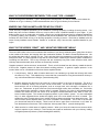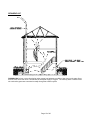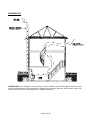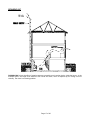
1
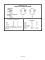
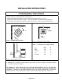
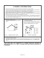
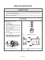
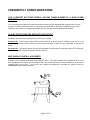
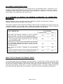
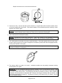
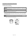
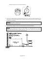
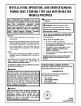
OWNER`S MANUAL
OIL BURNING STOVE
YUKON
Verified and tested following
CAN/CSA B140.3 et UL 896 standards by:
Intertek Testing Services
Manufactured by:
1700 Léon-Harmel
Québec, (Québec)
G1N 4R9
www.drolet.ca
Tel. : (418) 527-3060
Fax : (418) 527-4311
READ THESE INSTRUCTIONS AND SAVE FOR FUTURE REFERENCE
45045a _fev 03
TABLE OF CONTENT
TECHNICAL DATA ............................................................................................................................. 2
INSTALLATION INSTRUCTIONS ......................................................................................................... 3
POSITIONING THE STOVE ................................................................................................................... 3
CHIMNEY INFORMATIONS ................................................................................................................. 4
CONNECTING THE STOVE TO THE CHIMNEY................................................................................ 5
LEVELLING THE STOVE ...................................................................................................................... 6
FIXING THE STOVE TO THE FLOOR.................................................................................................. 6
CONNECTING THE STOVE TO THE OIL TANK............................................................................... 7
MEASURING AND ADJUSTING THE DRAFT .................................................................................... 8
OPERATING INSTRUCTIONS................................................................................................................ 9
COMBUSTIBLE ....................................................................................................................................... 9
LIGHTING ................................................................................................................................................ 9
CHANGING THE INTENSITY ............................................................................................................. 10
TURNING THE STOVE OFF ................................................................................................................ 11
MAINTENANCE .................................................................................................................................... 11
FREQUENTLY ASKED QUESTIONS .................................................................................................. 12
TROUBLE SHOOTING ........................................................................................................................... 20
LIMITED WARRANTY........................................................................................................................... 30
Page 1 of 30
TECHNICAL DATA
YUKON OIL BURNING APPLIANCE
COMBUSTIBLE :
HEAT INPUT :
Minimum :
Maximum :
FLOWRATE :
Minimum :
maximum :
MINIMUM DRAFT REQUIRED :
EFFICIENCY :
with fan :
without fan :
OIL NO 1
kW
BTU/h
4,8
16 600
10,7
36 800
cc/min
litres/h
7,8
0,47
17,3
1,04
0,05 INWC
%
77
73
CLEARANCES TO COMBUSTIBLES
Back
Side
Corners
Top
mm
180
150
150
915
OIL NO 2
kW
BTU/h
3,7
12 800
10,3
35 550
cc/min
litres/h
5,8
0,35
16,1
0,97
0,05 INWC
%
74,5
72
DIMENSIONS
in
7
6
6
36
Height :
Width :
Depth :
Flue pipe diameter:
Burner diameter :
A MINIMUM CLEARANCE OF 9’’ (230 mm)
FROM PIPE TO COMBUSTIBLES SHOULD BE
ALLOWED.
Glass ( 3 ) :
Weight :
Page 2 of 30
mm
745
620
675
130
200
in
29 ¼
24 ½
26 ½
5
8
144 x 264 5 11/16 x 10 13/32
84 kg
185 lbs
INSTALLATION INSTRUCTIONS
POSITIONING THE STOVE
•
•
•
•
Position the stove as close as possible to the chimney.
Many configurations are possible, the most frequent are illustrated in figures 1, 2 and 3.
Respect the clearances indicated on page 1. They reflect Canadian and American safety standards.
Always respect the clearances specified by the pipe manufacturers. Larger clearances always prevail.
Figure 1 : CORNER INSTALLATION
Figure 2 : PARALLEL INSTALLATION
Table 1 : CLEARANCES TO COMBUSTIBLES
Back
Side
Corners
Top
mm
180
150
150
915
in
7
6
6
36
Flue Pipe
230
9
Figure 3 : WALL INSTALLATION
• IMPORTANT: It is essential to ensure that the room in which the stove is installed is sufficiently ventilated
to provide an adequate air supply.
THE BURNING OF ONE LITRE OF FUEL (OIL) REQUIRES APPROXIMATELY 30 M3 OF AIR AND WILL
PRODUCE ABOUT 0.8 KG OF WATER VAPOR AND 9 M3 OF CARBONE DIOXIDE AND ATMOSPHERIC
NITROGEN. A SOURCE OF AIR COMING FROM OUTSIDE THE HOUSE IS NECESSARY TO REPLACE
COMBUSTION AIR. THIS IS ESPECIALLY TRUE IF YOUR HOUSE IS NEW AND WELL INSULATED.
Page 3 of 30
CHIMNEY INFORMATIONS
• Before you hook up the stove, inspect the chimney to ensure that it is in good condition.
• Your stove is approved on factory built type A or type L chimney. The chimney has to be well insulated; a
chimney with a cold internal surface can prevent a good draft and create condensation.
• Chimney sections must be of equal diameter. A 5" factory built chimney is required. A larger diameter will
have a greater volume and will be more difficult to heat. This can lead to draft problems.
• Masonry chimneys are often oversized. You must insert a 5” stainless steel liner in your oversized
masonry chimney in order to reduce its internal diameter to 5 inches.
• The chimney should be at least 15' high (including stove pipe sections). The chimney has to extend at
least 3’ above the point where is comes out of the roof and at least 2' higher than the tallest roof point or
any structure within a horizontal distance of 10’.
• MINIMUM CHIMNEY HEIGHT :
The height of the chimney should be at least 15’
(4.6 m).
• CLEARANCES WITH THE ROOF TOP AND
STRUCTURES NEARBY:
The chimney shall extend at least 2’ (0,6 m)
above the highest roof point or any structure
within an horizontal distance of 10’ (3,05 m).
Figure 4:
Figure 5:
MINIMUM CHIMNEY HEIGHT
CHIMNEY CLEARANCES
• CLEARANCE FROM THE ROOF :
• The chimney shall extend at least 3’ (0,91 m) above the point where it comes out of the roof and at least 2'
higher than the tallest roof point or any structure within a horizontal distance of 10’. ref.: standard B-139 4.2.2.11.
YOUR STOVE SHALL BE CONNECTED TO A CHIMNEY WHICH WILL PROVIDE AN
ADEQUATE DRAFT AT ALL TIMES TO ENSURE SAFE AND PROPER OPERATION OF
THE BURNER
Page 4 of 30
CONNECTING THE STOVE TO THE CHIMNEY
• The combustion residues are vented at the back of the stove. The female part of the black pipe connector
has to be inserted in the flue outlet of the stove. Secure all connections with 3 metal screws, positioned at
a 120o distance from one another.
• The connection between the black pipe and the chimney has to be perfectly airtight.
• A maximum horizontal length of 8 feet is allowed. Make sure you have a minimum slope of 1/4" per foot.
• Do not use more than two 90o elbows in your connections.
• It is strictly forbidden to pass through combustible materials walls, floors, or ceilings with a black pipe
connector.
DIRECT HORIZONTAL CONNECTION :
You can connect your stove to the chimney
using only a horizontal black pipe connector.
CEILING CONNECTION :
If your chimney starts at the ceiling level, use
one 90º elbow and the necessary black pipe
sections to reach the chimney.
Figure 6:
Figure 7:
DIRECT HORIZONTAL CONNECTION.
• THE CHIMNEY MUST NOT BE SHARED WITH
OTHER APPLIANCES.
• FIX THE BLACK PIPE CONNECTORS
TOGETHER WITH METAL SCREWS.
CEILING CONNECTION.
VERTICAL CONNECTION :
It is recommended not to use more than two (2)
90º elbows when connecting your stove to the
chimney. Otherwise, draft problems may occur.
• MAKE SURE YOU RESPECT A MINIMUM
SLOPE OF ¼’’ PER FOOT OF HORIZONTAL
PIPE LENGTH.
• RESPECT CLEARANCES TO COMBUSTIBLES
VERY CAREFULLY. THEY ARE PRESCRIBED
BY THE PIPE MANUFACTURER.
• PIPE CLEARANCES TO COMBUSTIBLES MAY
VARY DEPENDING ON THE TYPE AND THE
MANUFACTURER.
Figure 8:
Page 5 of 30
VERTICAL CONNECTION.
LEVELLING THE STOVE
• Now that the stove is into place and properly
hooked up to the chimney, you have to adjust the
level of the burner.
• Put the level on the burner’s rim, parallel to the
door.
(Figure 9A).
Screw or unscrew the
adjustable threaded legs to level the burner. Use
a 7/16" or 10 mm key.
• Put the level on the burner’s rim, parallel to the
sides. (Figure 9B). Screw or unscrew the
adjustable threaded legs to level the burner. Use
a 7/16" or 10 mm key
Figure 9A:
LEVELLING THE BURNER
Figure 9B:
LEVELLING THE BURNER
IMPORTANT :
IT IS VERY IMPORTANT THAT THE BURNER
ALWAYS BE LEVEL TO ALLOW A PROPER OIL
DISTRIBUTION INSIDE THE BURNER AND A
PROPER OIL VAPOR DISTRIBUTION THROUGH
THE CATALYTIC RINGS.
FIXING THE STOVE TO THE FLOOR
• The stove must be fixed in its location using the
two fixation brackets. Install the brackets on the
two adjustable back legs. (figure 11)
• If the floor is made of combustible material, it is
preferable to install the stove on a non
combustible surface that covers an area at least
equal to the size of the stove.
Figure 10:
Page 6 of 30
INSTALLATION OF FIXATION
BRACKETS
CONNECTING THE STOVE TO THE OIL TANK
• Make sure that the oil tank is 12" (305 mm) higher than the carburetor. This is very important, since the
stove is gravity fed.
• Use only copper piping to connect the tank to the stove.
• Make sure that there is a continuous slope going from the tank to the stove.
• A 1/4" slope per foot is needed on the tank itself, from front to back. This will keep residue accumulations
at the back of the oil tank. Otherwise, residues could clog the oil line.
• When the tank is installed outside the house, it is always preferable to use oil #1 in order to avoid
viscosity problems.
NOTE :
THE TANK SHALL BE LOCATED IN AN AREA WHERE IT WILL NOT BE EXPOSED TO THE
DIRECT RAYS OF THE SUN OR ADJACENT TO ANY SOURCE OF INTENSE HEAT.
Figure 11 :
OIL TANK CONNECTION
Page 7 of 30
MEASURING AND ADJUSTING THE DRAFT
• Your stove operates with a natural draft, created by the ascension of combustion gases in the chimney.
This movement creates a suction effect in the stove and forces ambient air to pass through the perforations
in the burner. That air is needed for combustion.
• To make sure the stove will function properly, it is essential that a draft reading be taken. The draft is
measured in inches of water column using a manometer. Your qualified technician should have this tool.
• The minimum draft requirement is 0,05 INWC. This is indicated on page one of the manual. The draft has
to be attained when the oil flow control knob is set at position #1.
• The draft can be taken using the hole located on the stove’s cooking surface, or using the opening on the
draft regulator (usually plugged by a rubber cap). The hole on the cooking surface is the best area.
IMPORTANT : ALWAYS MEASURE THE DRAFT WITH ALL AIR-MOVING EQUIPMENT OPERATING
(RANGE HOOD, BATHROOM FAN, AIR EXCHANGER, DRYER, ETC.)
ref. : standard CAN/CSA B-139 art. 4.1.5.
DRAFT REGULATOR
• An excessive draft is just as bad as one that is
too low.
• The regulator at the back of the stove controls
the draft if it becomes excessive.
• If the draft exceeds 0.08 INWC, the draft
regulator needs to be adjusted.
To adjust the draft regulator, you have to screw or
unscrew the counterweight located on the regulator.
If the regulator is open, it lowers the draft. If it is
closed, it increases it.
Figure 12:
DRAFT REGULATOR
THE ONLY RIGHT WAY OF MEASURING THE DRAFT IS BY USING A MANOMETER THAT GIVES A
READING IN INCHES OF WATER COLUMN. ANY OTHER METHOD (CANDLE, MATCHES, ETC.) ARE
UNRELIABLE.
INSTALLATION OF YOUR STOVE SHALL BE IN ACCORDANCE WITH THE CAN/CSA B-139
(INSTALLATION CODE FOR OIL-BURNING EQUIPMENT) IN CANADA AND THE NFPA 31 STANDARD
(NATIONAL FIRE PROTECTION ASSOCIATION STANDARD FOR OIL-BURNING EQUIPMENT) IN THE
UNITED STATES.
THE INSTALLATION SHOULD BE PERFORMED BY A QUALIFIED TECHNICIAN, MEMBER OF A
RECOGNIZED ASSOCIATION IN YOUR AREA.
Page 8 of 30
OPERATING INSTRUCTIONS
COMBUSTIBLE
• Your stove has been designed to work with oil #1 or #2. DO NOT USE GASOLINE, CRANKCASE OIL OR
ANY OIL CONTAINING GASOLINE. The manufacturer declines all responsibility regarding damages
caused by the use of other combustibles.
• Make sure to use oil without impurities which may plug the filters or the carburetor (valve). Impurities will
cause an improper combustion.
LIGHTING
BEFORE LIGHTING THE STOVE:
• Make sure that :
The tank is full;
The taps are open;
• Make sure that the (3) rings are in the right
position. Each of them is stamped with the
letter A, B, or C (figure 13).
• Make sure that the oil flow control knob is
set at « 0 » (figure 14B).
• If not already done, arm down the
carburetor’s lever located behind the stove
(figure 14A).
• Wait for the carburetor to fill up with oil and
let the level stabilize.
• BEFORE ATTEMPTING TO LIGHT YOUR
STOVE, MAKE SURE THAT THE OIL
FLOW CONTROL KNOB IS SET AT “0”.
Figure 13:
BURNER RINGS POSITION
Figure 14B: CARBURETOR (VALVE)
Figure 14A:
ARMING / DISARMING THE CARBURETOR
(VALVE)
Page 9 of 30
LIGHTING (CONT’D)
• Set the oil flow control knob at "1". As soon as the oil starts flowing into the burner, set it back to
"0".
• Open the door and pour 2 to 3 ounces (app. 75 ml) of lighting gel or wood alcohol into the burner.
NOTE : USING LIGHTING GEL IS BETTER AND SAFER.
• With a long wood match or a BBQ lighter, ignite and close the door. The burning gel will allow the
burner and exhaust system to warm up.
• After a few minutes (before the fire goes out), set the oil flow control knob at “1”.
• Increase the oil flow by one position every ten minutes until you reach the desired intensity.
Note : Never leave matches, paper, or other materials in the burner.
IF LIGHTING FAILS, ALWAYS WAIT FOR THE BURNER TO COOL DOWN
TO ROOM TEMPERATURE BEFORE USING WOOD ALCOHOL AGAIN.
IF, FOLLOWING A LIGHTING FAILURE, THE BURNER FINDS ITSELF
WITH AN EXCESS QUANTITY OF OIL, ALL OF THE OIL MUST FIRST BE
REMOVED BEFORE LIGHTING THE STOVE AGAIN.
CHANGING THE INTENSITY
• Waiting 10 minutes before increasing the oil flow by one position will allow the flame to stabilize and will
prevent soot build-up.
• No waiting is needed when decreasing the oil flow.
Page 10 of 30
TURNING THE STOVE OFF
• Set the oil flow control knob to position “0”.
• If you plan on keeping the stove off for a long period of time, it is recommended that you disarm the
carburetor’s lever and close the taps on the oil line.
ALWAYS KEEP THE CARBURETOR SHUT OFF WHEN THE BURNER IS NOT OPERATING
MAINTENANCE
ONCE A WEEK :
• Clean the burner oil inlet tube with the cleaning
tee :
Push the rod of the cleaning tee toward the
inside of the burner while turning it at the
same time.
Move back and forth 2 or 3 times;
Pull it back into place to finish the operation.
Figure 15 : CLEANING TEE
WHEN YOUR STOVE IS WORKING, ALWAYS KEEP THE CLEANING TEE LEVER PULLED BACK INTO
PLACE.
ONCE A MONTH :
• Clean the following parts with a steel wool;
- the burner;
- the burner rings.
AT THE BEGINNING OF EACH HEATING SEASON :
• Clean the carburetor’s filter and replace the tank’s filter;
• Inspect the firebox through the opening of the rear flue outlet.;
• Clean the chimney and pipe connectors.
MAKE SURE THAT EVERYTHING IS CLOSED BEFORE STARTING THE CLEANING PROCEDURES.
IF NECESSARY :
• Clean the door glasses.
• Always clean the glasses when the stove is cold. Use products specifically designed for this purpose or a
water and vinegar solution.
REPAIRING
• Ask your Drolet dealer to provide you with the appropriate replacement (Borofloat) glass 3.3mm. Do not use
substitute materials.
• To replace the glass, remove the screws of the glass retainers inside the door. Remove the retainers and
replace the damaged piece with a new one. Reinstall glass retainers and screws.
• If the door gasket is damaged, replace it with an identical one. To get a new gasket, refer to your Drolet
dealer.
Page 11 of 30
FREQUENTLY ASKED QUESTIONS
CAN I CONVERT MY STOVE FROM A YELLOW FLAME BURNER TO A BLUE FLAME
BURNER?
Your stove has been tested and certified according to North-American standards with a specific burner, which
produces a yellow or blue flame effect. It is therefore strictly forbidden to bring any modification to your stove.
Otherwise, your insurance coverage could cease and your warranty would be automatically nullified.
CAN MY STOVE FUNCTION WITHOUT ELECTRICITY?
Absolutely. Since the stove is gravity fed, no electricity is required.
Exception #1: If the oil tank is lower than the stove and that an electric pump is needed to bring the oil to the
burner, you will not be able to operate the stove without electricity, unless you use a generator to activate the
pump.
Exception #2: The optional blower and the wall thermostat kit both possess components that run on electricity.
You will not be able to use these options without electricity.
WHY SHOULD I INSTALL A BLOWER?
A blower can be installed at the back of your DROLET stove. This option enables you to redistribute into a room
the heat trapped at the back of your stove. By forcing hot air toward the front, the blower enables you to extend the
radiation power of your stove. If you do not have a blower and would like to purchase one, please consult our
accessories section at www.drolet.ca
Page 12 of 30
DO I NEED A FLOOR PROTECTION?
You do not need a floor protection if your stove already sits on a non-combustible surface. Furthermore, it is not
necessary to install a floor protection if your stove sits on a wood floor. However, any floor that is made of
combustible synthetic material (ex: carpet) needs to be covered with a floor protection. In all cases, your best
bet is prudence. Everywhere there is fire, there is a risk.
IS IT POSSIBLE TO REDUCE THE MINIMUM CLEARANCES TO COMBUSTIBLE
MATERIALS?
Before you read this section, please take note that the information supplied in the table below is based on
Canadian standards and may not apply to other countries.
The minimum clearances can be reduced by installing a protective shield. The shield can be made of various noncombustible materials, such as ceramic, brick or metal. After installing a heat shield, the minimum clearances
indicated on the stove’s certification plate can be reduced as summarized in the table below:
Percentage of clearance reduction
using shielding
TYPE OF PROTECTION
Sides and back
Top
Sheet metal, with minimum thickness of 0,013" (0,33mm),
spaced out at least 1" (25.4mm) by non-combustible spacers.
67%
50%
Ceramic tiles, or an equivalent non-combustible material installed
on a non-combustible support, spaced out at least 1" (25.4mm)
by non-combustible spacers.
50%
33%
Ceramic tiles, or an equivalent non-combustible material installed
on non-combustible supports with a minimum of 0,013" (0,33mm)
sheet metal backing spaced out at least 1" (25.4mm) by noncombustible spacers.
67%
50%
Brick, spaced out at least 1" (25.4mm) by non-combustible
spacers.
50%
N/A
67%
N/A
Brick, with a minimum of 0,013" (0,33 mm) sheet metal backing
spaced out at least 1" (25.4mm) by non-combustible spacers.
Source: CSA Standard B365-1991, Table 4, Page 27
WHAT TYPE OF EXHAUST SYSTEM DO I NEED?
Your exhaust system should be comprised of two main elements: a chimney and a connector (commonly called
stove pipe). There exists two types of chimneys for oil stoves: type A and type L chimneys. The chimney is hooked
up to the stove using the connector, which is made of steel with a minimum thickness of 24 ga. The connector
cannot go through ceilings, closets, floors, or any other combustible material. Only type A insulated chimney can
go through combustible material and out to the exterior of the house, as per the manufacturer’s specifications.
Page 13 of 30
WHAT IS THE DIFFERENCE BETWEEN TYPE A AND TYPE L CHIMNEY?
Type A chimneys have insulation. Type L chimneys have a double wall. It is the air “cushion” that creates the
insulation on a Type L chimney. Drolet recommends the use of a Type A chimney for its oil stoves.
WHERE CAN I FIND AN INSTALLER FOR MY OIL STOVE?
There are many companies specializing in the installation of heating equipment, including oil burning stoves. Your
dealer may have its own installation service or may be able to refer a qualified installer for your region. If your
dealer cannot put you in contact with an installer, consult your local directories and look for companies specializing
in “plumbing, heating, and ventilation”. Companies that provide installation and maintenance services for fuel oil
furnaces can often install all king of oil burning equipment, including oil stoves. Drolet has a database with the
name of many installers across Canada. Contact us so that we verify if we can refer a qualified installer for your
region.
WHAT DO THE WORDS “DRAFT” AND “NEGATIVE PRESSURE” MEAN?
The word “draft” refers to the hot air movement that circulates in your stove’s exhaust system, going from the stove
to the outside of the house, and carrying with it the combustion residues. The draft is a natural phenomenon. Hot
air weights less than cold air, causing it to rise. This is why the higher the temperature in the exhaust system, the
stronger the draft. It is also important to say that the “tunnel effect” created by the exhaust system contributes to
increasing the draft effect. This is why chimneys that are excessively long often create excessive draft, while
chimneys that are abnormally short will have an excessively low draft.
“Negative pressure” can be seen as a “reverse draft”. That is, air will circulate from the chimney toward the interior
of the house. Negative pressure is often what causes smoking problems. In general, negative pressure is the
result of either one or a combination of the three factors explained below:
1- A cold chimney. Cold air, which is heavier that hot air, has a tendency to go down the chimney and create
the effect of a “clog”. This explains why a stove that has not worked for a long time and which chimney is
very cold will sometimes be hard light. (consult drawing #2C).
2- Negative pressure can also occur as a result of a “vacuum effect” in the room or the house. The air in a
house is constantly moving. Hot air rises, cold air moves down. Air can also be expulsed outside of the
house with the use of air-moving equipment, such as a range hood, a air exchanger, a bathroom fan, a
dryer, etc. Furthermore, air goes in and out of the house through cracks, doors, windows, etc. If air leaves
a room without being replaced, a “vacuum effect” is created. Therefore, if a house is well insulated and all
windows are closed, the room will source its air through the easiest alternative route, which is often your
stove’s exhaust system. This creates a negative pressure in your exhaust system. You now understand
why it is often suggested that a window be slightly open in the room where the stove is located. This
enables the room to easily source its air outside the house without searching for an alternative route. The
vacuum effect can be amplified when your stove is located in the basement. This is due to the fact that
your house itself acts like a chimney. Since hot air will rise to upper floors in the house, it will “draw” air
from the basement of the house. This is called the “chimney stack effect”. (consult drawings #3C).
3- Wind can also be a third cause of negative pressure. When your house is located near a structure which
height is superior to your chimney’s, wind currents can create an interference with your chimney, leading
to negative pressure problems. (consult drawing #4C and #5C).
Page 14 of 30
DRAWING #1C
DRAWING #1C shows a stove functioning under normal and adequate conditions. Heat rises to the upper floors
and the room where the stove is located has an adequate supply of oxygen. The chimney draft is sufficient and
the combustion gases are evacuated normally through the exhaust system.
Page 15 of 30
DRAWING #2C
DRAWING #2C shows the effect of a cold chimney. Cold air creates a reverse draft (negative pressure), which
causes smoking problems. This phenomenon is amplified by the fact that heat rises, which creates a draft from
the basement of the house to the upper floors (“chimney stack effect”).
Page 16 of 30
DRAWING #3C
DRAWING #3C shows the effect of negative pressure caused by an air-moving device inside the house. In the
example above, the range hood draws air from inside the house, which is replaced by air coming from the
chimney. The result is a smoking problem.
Page 17 of 30
DRAWING #4C
DRAWING #4C shows the negative pressure effect caused by wind, influenced by nearby structures such as a
building.
Page 18 of 30
DRAWING #5C
DRAWING #5C shows the negative pressure effect that can be caused by wind, influenced by nearby structures
such as a tree.
Page 19 of 30
WHEN DO I NEED TO REPLACE MY DOOR GASKET WHAT TYPE OF GASKET DO I
NEED TO BUY?
The gasket is there to insure that your stove remains air tight, which is necessary for your stove to function
properly. How frequently you replace the gasket really depends on how often you fire your stove. When the gasket
becomes really hard and that you notice an gap between the door and the stove, it is time to replace it. If you fire
your stove on a regular basis during all winter, you may need to replace the gasket before every heating season.
We strongly suggest that you use the genuine gasket supplied by the manufacturer. The genuine gasket has a
better density and comes with a special adhesive. It will last much longer. Avoid liquid glue and low density
gasket, with large and flabby knits. To obtain the genuine gasket replacement kit for your stove, please consult our
accessories section at www.drolet.ca
WHY DID THE STAINLESS STEEL DEFLECTOR INSIDE MY STOVE TARNISH?
The tarnishing of the stainless steel deflector is absolutely normal. The role of this deflector is to reflect heat, as
well as protect the firebox. It is not a decorative accessory. We use stainless steel because it is an extremely heat
resistant material that will provide the best protection for the long term durability of your stove’s firebox. The only
inconvenient of stainless steel is its tendency to tarnish when it is exposed to intense heat.
TROUBLE SHOOTING
WHY DOES THE GLASS GET SO DIRTY?
Possible causes and solutions :
1- The door is not properly closed or there is a gap between one of the glass lamellas. The door gasket could
also be too old. The air that goes into your stove through openings (other than the openings in the burner)
can cause a instability in the combustion process, resulting in sooth deposits on the glass.
Solution : The door must be closed at all times. Make sure that the glass lamellas are tightly in place.
Furthermore, if the door gasket is too old and does not seal the door properly, replace it.
2- The burst disc located on the top of the stove is not put in place properly. The air that goes into your stove
through openings (other than the openings in the burner) can cause instability in the combustion process,
resulting in sooth deposits on the glass.
Solution : Make sure that the burst disc is put in place properly. It should be even with the top of the stove.
Page 20 of 30
3- The catalytic rings are not in the right position, causing instability in the combustion process.
Solution : Each ring is stamped with the letters “A”, “B”, or “C” . The location of each ring is very
important. Ring “A” is always the top ring, “B” is the middle one, and “C” is the bottom one.
4- The burner is not level. This prevents an even dispersion of the oil on the burner surface. When too much
oil is accumulated in one spot, there is not enough air to allow for a complete combustion, which creates
sooth deposits on the glass.
Solution: Make sure the burner is level. Put a level on top of the burner. Then, adjust the stove’s
threaded legs accordingly.
Step #1 : level the burner in the east/west direction.
Page 21 of 30
Step #2: level the burner in the north/south direction.
5- The burner is dirty. A burner that has not been cleaned on a regular basis will accumulate residues, which
will end up clogging the burner holes. This causes instability in the combustion process, resulting in sooth
deposits on the stove’s glass.
Solution: Visually inspect the burner on a weekly basis. Remove residues by scrubbing the burner with a
steel wool. Use an industrial vacuum cleaner (ex: “Shop Vac”) to collect the remaining dirt.
6- The oil flow has been increased to rapidly.
Solution: Decrease the oil flow back to position #1. Allow a few minutes for the combustion to become
stable. Increase the oil flow by one position every 10 minutes until you reach the desired intensity.
7- The draft regulator at the back of the stove needs lubrication. If the draft regulator does not open freely,
the stove may not get the air it needs to complete the combustion process and reach the appropriate draft,
causing sooth deposits on the glass.
Solution : Make sure that the draft regulator at back of the stove opens and closes freely. Apply a
lubricant (ex: WD40) on moving parts.
8- The chimney draft is too weak. As a result, combustion residues are not properly evacuated, causing
sooth deposits on the glass.
Solution #1 : The lack of adequate draft may simply be caused by a lack of heat inside the chimney. Start
the fire by pouring 2 onzes (50ml) of fire-lighting gel into the burner. Do not turn the oil on right away (leave
the oil flow control knob at zero). The burning gel will allow the chimney to heat up until it reaches a
temperature that will generate an adequate draft. When the burning gel’s intensity starts to diminish, turn
the oil flow control knob to position #1. Increase the oil flow by one position every 10 minutes until you
reach the desired intensity.
Page 22 of 30
Solution#2 : The lack of adequate draft may be due to an improper adjustment of the draft regulator
located at the back of the stove. The draft regulator should have been adjusted by a qualified technician
when the stove was installed. If this has not been done, have a qualified technician take a draft reading
and adjust the draft regulator. Your qualified technician must use a manometer to obtain a draft reading.
During this procedure, the oil flow control knob must be set at position #1 and all air-moving equipment
inside the house (range hood, heat exchanger, bathroom fan, etc.) must be in operation. The reading on
the manometer must correspond to the minimum prescribed draft indicated on the certification plate located
at the back of the stove. The prescribed draft is set at 0,05 INWC for most oil stoves. If the adjustment of
the draft regulator does not increase the chimney draft, go to solutions #3 to #6.
Solution #3: Your stove may be located in an area where the volume of oxygen is not sufficient to allow
for a complete combustion. If there is a window in the room where the stove is located, open it by at least 2
inches. If this solves the problem, it may indicate that your house is over-insulated or the room is too small.
Without an additional supply of oxygen, your stove will not function normally. The ideal solution is to install
a permanent fresh air intake located at a distance of 6 to 12 inches from the stove.
Solutions #4: Your exhaust system may be toot short. In order to obtain a sufficient draft, your exhaust
system must have a minimum height. A minimum height of 15 feet (from the connector at the back of the
stove to the chimney cap outside the house) will be adequate in most cases. HOWEVER: remember that
longer is not always better. An exhaust system that is excessively high may be difficult to pre-heat and
control. If your exhaust system is too short, add some chimney sections.
Solution #5: Your exhaust system may be too tortuous or may not have the minimum slope required to
allow for a proper draft. Your exhaust system should never have more than two 90o elbows. Furthermore,
the horizontal sections of your exhaust system should be as short as possible (maximum 8’) and must have
a minimum upward slope of ¼” per foot.
Solution #6: Your chimney may be oversized. The effect of an oversized chimney is generally the
reduction of the temperatures inside the chimney, due to the larger volume that needs to be heated. This
weakens the chimney draft. Our oil stoves are tested to be installed on a chimney with an interior diameter
of 5 inches (127mm). If you do not have a 5” chimney, you can insert a stainless steel liner inside the
existing chimney in order to reduce its interior diameter to 5 inches. This will help keep chimney
temperatures higher, therefore increasing the chimney draft.
WHY IS THERE ODORS OR OCCASIONAL SMOKING PROBLEMS?
Possible causes and solutions :
1- The room where the stove is located is under a negative pressure effect.
Solution #1: If this situation occurs when you light-up the stove, it is probably due to the fact that the
chimney is very cold. Start your stove by pouring approximately 2 onzes (50ml) of fire-lighting gel into the
burner. Do not turn the oil on right away (leave the oil flow control knob at zero). The burning gel will allow
the chimney to heat up until it reaches a temperature that will generate an adequate draft. When the
burning gel’s intensity starts to diminish, turn the oil flow control knob to position #1. Increase the oil flow
by one position every 10 minutes until you reach the desired intensity.
Solution #2: Check if this situation occurs when air-moving devices are working (range hood, heat
exchanger, bathroom fan, etc.). If so, make sure you turn those systems off when you operate the stove. If
this is not possible, you will need to install a permanent fresh air intake near to stove in order to replace the
air that is sucked out of the house by your ventilation systems. The fresh air intake should be install at a
distance of 6 to 12 inches from the stove.
Page 23 of 30
Solution #3: The negative pressure effect may be caused by the wind blowing into your chimney. This is
often caused by the interference of nearby structures. In order to avoid such interference, your chimney
should be higher (by at least two feet) than any structure located in a horizontal distance of 10 feet. Most
houses located in residential areas do not have structures located within a 10 foot distance of the chimney,
other that the house’s own roof top. It this is your case, you must make sure that the chimney exceeds the
highest roof point by at least 2 feet.
WHY DID THE FIRE GO OUT?
Possible causes and solutions :
1- The oil tank is empty and/or the taps are closed.
Solution: Verify that there is oil in the tank and that the taps are open. If the tank is empty, fill-it up. Then,
verify that the oil reaches the burner by leaving the stove’s oil flow control knob at position #1 for a few
seconds. You should be able to see and touch a thin layer of oil inside the burner.
2- The carburetor’s small float compartment is full of oil and activates the safety mechanism. This generally
occurs when the oil is injected too rapidly in a new or empty carburetor. If this situation has occurred, you
will not be able to operate the stove properly until all the oil is removed from the small float compartment.
Solution : Remove the 4 screws on the silver data plate located on top pf the carburetor. Then, remove
the 3 screws that retain the top portion of the carburetor. With a needle, grab the little float located in the
small compartment. Remove the oil with a sponge. BE CAREFULL: if you are not sure about what you
are doing, consult a qualified technician. If you remove the wrong screws, you may disarrange the
carburetor, which will need to be replaced.
3- The oil tank is located outside the house and you are burning oil #2. When the outside temperature is very
cold, the flow of oil #2 can be greatly reduced. Therefore, your stove may not have the oil flow necessary
to operate at its full capacity.
Solution : Always use oil #1 when your oil tank is located outside. Furthermore, we recommend that you
use a copper pipe with a 1” diameter to link the oil tank to the house. The copper pipe must however keep
a 3/8” diameter when it is inside the house.
4- The oil tank filter is clogged. This can occur when the filter is not periodically replaced.
Solution: Ideally, replace the oil tank filter at the beginning of each heating season. Furthermore, in order
to avoid the risk of blocking the filter with oil tank residues, it is recommended that your oil tank be installed
with a horizontal slope of at least ¼” per foot. This will help concentrate the accumulation of residues at the
back of the oil tank instead of near the tap entry.
Page 24 of 30
5-
The carburator’s filter is clogged.
Solution : Clean the carburetor’s filter. Start by closing all taps. Remove the two screws on the small
silver plate on the side of the carburetor. Then, remove the rubber joint and the nylon filter. Clean the filter
with hot water. Put everything back into place.
6- The chimney draft is too weak. This causes the fire to slowly go out.
Solution #1 : The lack of adequate draft may simply be caused by a lack of heat inside the chimney. Start
the fire by pouring 2 onzes (50ml) of fire-lighting gel into the burner. Do not turn the oil on right away (leave
the oil flow control knob at zero). The burning gel will allow the chimney to heat up until it reaches a
temperature that will generate an adequate draft. When the burning gel’s intensity starts to diminish, turn
the oil flow control knob to position #1. Increase the oil flow by one position every 10 minutes until you
reach the desired intensity.
Solution#2 : The lack of adequate draft may be due to an improper adjustment of the draft regulator
located at the back of the stove. The draft regulator should have been adjusted by a qualified technician
when the stove was installed. If this has not been done, have a qualified technician take a draft reading
and adjust the draft regulator. Your qualified technician must use a manometer to obtain a draft reading.
During this procedure, the oil flow control knob must be set at position #1 and all air-moving equipment
inside the house (range hood, heat exchanger, bathroom fan, etc.) must be in operation. The reading on
the manometer must correspond to the minimum prescribed draft indicated on the certification plate located
at the back of the stove. The prescribed draft is set at 0,05 INWC for most oil stoves. If the adjustment of
the draft regulator does not increase the chimney draft, go to solutions #3 to #6.
Solution #3: Your stove may be located in an area where the volume of oxygen is not sufficient to allow
for a complete combustion. If there is a window in the room where the stove is located, open it by at least 2
inches. If this solves the problem, it may indicate that your house is over-insulated or the room is too small.
Without an additional supply of oxygen, your stove will not function normally. The ideal solution is to install
a permanent fresh air intake located at a distance of 6 to 12 inches from the stove.
Page 25 of 30
Solutions #4: Your exhaust system may be toot short. In order to obtain a sufficient draft, your exhaust
system must have a minimum height. A minimum height of 15 feet (from the connector at the back of the
stove to the chimney cap outside the house) will be adequate in most cases. HOWEVER: remember that
longer is not always better. An exhaust system that is excessively high may be difficult to pre-heat and
control. If your exhaust system is too short, add some chimney sections.
Solution #5: Your exhaust system may be too tortuous or may not have the minimum slope required to
allow for a proper draft. Your exhaust system should never have more than two 90o elbows. Furthermore,
the horizontal sections of your exhaust system should be as short as possible (maximum 8’) and must have
a minimum upward slope of ¼” per foot.
Solution #6: Your chimney may be oversized. The effect of an oversized chimney is generally the
reduction of the temperatures inside the chimney, due to the larger volume that needs to be heated. This
weakens the chimney draft. Our oil stoves are tested to be installed on a chimney with an interior diameter
of 5 inches (127mm). If you do not have a 5” chimney, you can insert a stainless steel liner inside the
existing chimney in order to reduce its interior diameter to 5 inches. This will help keep chimney
temperatures higher, therefore increasing the chimney draft.
WHY IS THE FLAME PATTERN UNSTABLE?
Possible causes and solutions :
1- The chimney is oversized. The effect of an oversized chimney is generally the reduction of the
temperatures inside the chimney, due to the larger air volume that needs to be heated. This weakens the
chimney draft, which can cause instability in the flame pattern.
Solution: Our oil stoves are tested to be installed on a chimney with an interior diameter of 5 inches
(127mm). If you do not have a 5” chimney, you can insert a stainless steel liner inside the existing chimney
in order to reduce its interior diameter to 5 inches. This will help keep chimney temperatures higher,
therefore increasing the chimney draft and stabilizing the flame pattern.
2- The chimney is too long. The longer the chimney, the longer it takes to reach the adequate draft and
stabilize the flame pattern.
Solution: Start the fire by pouring 4 onces (100ml) of fire-lighting gel into the burner. Do not turn the oil on
right away (leave the oil flow control knob at zero). The burning gel will allow the chimney to heat up until it
reaches a temperature that will generate an adequate draft. When the burning gel’s intensity starts to
diminish, turn the oil flow control knob to position #1. Increase the oil flow by one position every 10 minutes
until you reach the desired intensity. This lighting procedure should allow the chimney to heat up until it
reaches a temperature that will generate an adequate draft and stabilize the flame pattern.
3- The flame pattern may be disturbed by the wind blowing into your chimney. This is often caused by the
interference of nearby structures.
Solution : In order to avoid the interference of nearby structures, your chimney should be higher (by at
least two feet) than any structure located in a horizontal distance of 10 feet. Most houses located in
residential areas do not have structures located within a 10 foot distance of the chimney, other that the
house’s own roof top. It this is your case, you must make sure that the chimney exceeds the highest roof
point by at least 2 feet. You can also use a chimney cap that is specifically designed to reduce the effects
of wind. Your retailer will be able to provide you with the part you need.
Page 26 of 30
WHY DOESN’T MY STOVE PRODUCE ENOUGH HEAT?
Possible causes and solutions :
1- The oil flow control knob is set too low.
Solution #1: Increase the oil flow control knob by one position every 10 minutes until the desired intensity
is reached. DO NOT MODIFY THE ADJUSTMENTS ON THE CARBURATOR. The adjustments on the
carburetor are done at the factory level, using specialized equipment. By trying to adjust the carburetor
yourself, you will worsen the problem.
Solution #2: Verify that the cleaning tee rod is completely pulled out toward the exterior of the burner. If
the cleaning tee rod extends to far into the burner, it can overheat. This can cause the small orange rubber
joint to melt and partially block the oil entry into the burner.
2- The stove is not level and the carburetor is sitting lower than the burner. Since your stove is gravity fed, it
is essential that the oil be able to flow from the carburetor to the burner. For this to occur, the carburetor
must be sitting at a higher level that the burner. The burner must also be level in order to allow for a
uniform dispersion of the oil.
Solution: Make sure that the carburetor is sitting higher than the burner. Then, make sure that the burner
is level. Put a level on top of the burner and adjust the stove’s threaded legs accordingly.
Step #1 : level the burner in the east/west direction.
Page 27 of 30
Step #2: level the burner in the north/south direction..
3- The oil tank is located outside the house and you are burning oil #2. When the outside temperature is very
cold, the flow of oil #2 can be greatly reduced. Therefore, your stove may not have the oil flow necessary
to operate at its full capacity.
Solution : Always use oil #1 when your oil tank is located outside. Furthermore, we recommend that you
use a copper pipe with a 1” diameter to link the oil tank to the house. The copper pipe must however keep
a 3/8” diameter when it is inside the house.
4- The oil tank filter is clogged. This can occur when the filter is not periodically replaced.
Solution: Ideally, replace the oil tank filter at the beginning of each heating season. Furthermore, in order
to avoid the risk of blocking the filter with the oil tank residues, it is recommended that your oil tank be
installed with a horizontal slope of at least ¼” per foot. This will help concentrate the accumulation of
residues at the back of the oil tank instead of near the tap entry.
Page 28 of 30
4- The carburetor’s filter is clogged, which reduces the oil flow.
Solution : Clean the carburetor’s filter. Start by closing all taps. Remove the two screws on the small
silver plate on the side of the carburetor. Then, remove the rubber joint and the nylon filter. Clean the filter
with hot water. Put everything back into place.
5- The chimney draft is too weak or too strong.
Solution #1: In the case of a chimney draft that is too weak, the problem may simply be caused by a lack
of heat inside the chimney as a result of an inadequate lighting procedure. Start the fire by pouring 2 onces
(50ml) of fire-lighting gel into the burner. Do not turn the oil on right away (leave the oil flow control knob at
zero). The burning gel will allow the chimney to heat up until it reaches a temperature that will generate an
adequate draft. When the burning gel’s intensity starts to diminish, turn the oil flow control knob to position
#1. Increase the oil flow by one position every 10 minutes until you reach the desired intensity.
Solution #2 : A draft that is too strong or too weak may be the result of an improper adjustment of the
draft regulator located at the back of the stove. The draft regulator should have been adjusted by a
qualified technician when the stove was installed. If this has not been done, have a qualified technician
take a draft reading and adjust the draft regulator. Your qualified technician must use a manometer to
obtain a draft reading. During this procedure, the oil flow control knob must be set at position #1 and all airmoving equipment inside the house (range hood, heat exchanger, bathroom fan, etc.) must be in operation.
The reading on the manometer must correspond to the minimum prescribed draft indicated on the
certification plate located at the back of the stove. The prescribed draft is set at 0,05 INWC for most oil
stoves.
Solution #3 : If the chimney draft remains too weak, Your stove may be located in an area where the
volume of oxygen is not sufficient to allow for a complete combustion. If there is a window in the room
where the stove is located, open it by at least 2 inches. If this solves the problem, it may indicate that your
house is over-insulated or the room is too small. Without an additional supply of oxygen, your stove will not
function normally. The ideal solution is to install a permanent fresh air intake located at a distance of 6 to
12 inches from the stove.
Solution #4 : Your exhaust system may be toot short. In order to obtain a sufficient draft, your exhaust
system must have a minimum height. A minimum height of 15 feet (from the connector at the back of the
stove to the chimney cap outside the house) will be adequate in most cases. HOWEVER: remember that
longer is not always better. An exhaust system that is excessively high may be difficult to pre-heat and
control. If your exhaust system is too short, add some chimney sections.
Solution #5: Your exhaust system may be too tortuous or may not have the minimum slope required to
allow for a proper draft. Your exhaust system should never have more than two 90o elbows. Furthermore,
the horizontal sections of your exhaust system should be as short as possible (maximum 8’) and must have
a minimum upward slope of ¼” per foot.
Solution #6: Your chimney may be oversized. The effect of an oversized chimney is generally the
reduction of the temperatures inside the chimney, due to the larger volume that needs to be heated. This
weakens the chimney draft. Our oil stoves are tested to be installed on a chimney with an interior diameter
of 5 inches (127mm). If you do not have a 5” chimney, you can insert a stainless steel liner inside the
existing chimney in order to reduce its interior diameter to 5 inches. This will help keep chimney
temperatures higher, therefore increasing the chimney draft.
Solution #7: In the case of excessive draft, it is possible to install a second draft regulator located within
the first 18 inches on the stove connector. Your dealer will be able to supply the appropriate part.
Page 29 of 30
1700, rue Léon-Harmel, Québec (Québec) G1N 4R9
tel. : (418) 527-3060 fax : (418) 527-4311
e-mail : [email protected] web site : drolet .ca
LIMITED WARRANTY
The warranty of the manufacturer extends only to the original consumer purchaser and is not transferable. This warranty covers
brand new products only, which have not been altered, modified nor repaired since shipment from factory. Proof of purchase
(dated bill of sale), model name and serial number must be supplied when making any warranty claim to your Drolet dealer.
This warranty applies to normal residential use only. Damages caused by misuse, abuse, improper installation, lack of
maintenance, over firing, negligence or accident during transportation are not covered by this warranty.
This warranty does not cover any scratch, corrosion or discoloration caused by over firing, abrasives or chemical cleaners. Any
defect or damage caused by the use of unauthorized parts or others than original parts void this warranty.
An authorized qualified technician must perform the installation in accordance with the Instructions supplied with this product
and all local and national building codes. Any service call related to an improper installation is not covered by this warranty.
Returned products are to be shipped prepaid to the manufacturer for investigation. If a product is found to be defective, the
manufacturer will repair or replace such defect and reasonable transportation fees will be refund. Repair work covered by the
warranty, executed at the purchaser domicile by an authorized qualified technician requires the prior approval of the
manufacturer Labour cost and repair work to the account of the manufacturer are based on predetermined rate schedule and
must not exceed the wholesale price of the replacement part.
The manufacturer at its discretion may decide to repair or replace any part or unit after inspection and investigation of the defect
.The manufacturer may, at its discretion, fully discharge all obligations with respect to this warranty by refunding the wholesale
price of any warranted but defective parts
The manufacturer shall in no event be responsible for any special, indirect, consequential damages of any nature, which are in
excess of the original purchase price of the product.
WARRANTY APPLICATION
DESCRIPTIION
PARTS
LABOUR
5 YEARS
Combustion chamber (Weldings Only)
Stainless Baffle
Carbon Steel Baffle
Coil Handle
Cast Iron parts
5 years
5 years
2 years
5 years
5 years
1 year
1 year
n/a
1 year
Ceramic glass (thermal breakage only)
1 YEAR
N/A
Burner
1 YEAR
1 year
Gaskets, Blower, Switch (thermodisc), Rheostat, Paint, Burner Rings,
Catalyst Ring
1 YEAR
n/a
Valve (Carburetor)***
1 year
Gold Plating (Tarnishing Only)
5 years
***Note : No modification or adjustment to the valve is permitted. Any changes to the valve void the warranty.
1 year
1 year
Shall your unit or a components be defective, contact immediately your Drolet dealer. Prior to your call make sure you have the
following information necessary to your warranty claim treatment:
•
•
You name, address and telephone number;
Bill of sale, dealer’s name;
•
Serial number and model name as indicated on the
nameplate fixed to the back of your unit;
•
Nature of the defect and any relevant information.
Before shipping your unit or defective component to our plant, you must obtain from your Drolet dealer an Authorization
Number. Any merchandise shipped to our plant without authorization will be refused automatically and returned to sender.
Page 30 of 30