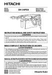
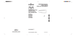
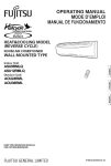
1
10” TABLE SAW WITH LASER & STAND
MODEL NO: CTS13L
PART NO: 6500820
OPERATION & MAINTENANCE
INSTRUCTIONS
LS0813
INTRODUCTION
Thank you for purchasing this CLARKE product. The table saw has been
designed to perform the sawing operation of ripping, cross-cutting, bevelling
and mitring in wood, wood products and plastics. This unit is designed for use
with a 250 mm carbide tipped blade.
Before attempting to use this product, please read this manual thoroughly and
follow the instructions carefully. In doing so you will ensure the safety of yourself
and that of others around you, and you can look forward to your purchase
giving you long and satisfactory service.
GUARANTEE
This product is guaranteed against faulty manufacture for a period of 12
months from the date of purchase. Please keep your receipt which will be
required as proof of purchase.
This guarantee is invalid if the product is found to have been abused or
tampered with in any way, or not used for the purpose for which it was
intended.
Faulty goods should be returned to their place of purchase, no product can
be returned to us without prior permission.
This guarantee does not effect your statutory rights.
CONTENTS
The following items should be supplied in the cartons. If any parts are missing,
do not operate your table saw until the missing parts are replaced. Failure to
follow this rule could result in serious injury.
1 x Table Saw c/w Stand Assembly (Fitted)
1 x Mitre Guide Fence
2 x Side Table Extensions
1 x Upper Blade Guard
4 x Side Table Extension Support Brackets
1 x Extraction Hose
1 x Wheel & Axle Assembly
1 x Push-stick
1 x Parallel Fence Clamp / Mount Assembly
1 x 250 mm TCT Blade (Fitted)
1 x Parallel Fence
2 x Small Parts / Fixings Pack
1 x Mitre Guide Assembly
2
Parts & Service: 020 8988 7400 / E-mail: [email protected] or [email protected]
SAFETY WARNINGS
CAUTION: DO NOT LET FAMILIARITY WITH YOUR TABLE SAW MAKE YOU
CARELESS. REMEMBER THAT A CARELESS FRACTION OF A SECOND IS
SUFFICIENT TO CAUSE SEVERE INJURY.
PERMITTED USAGE
3. Keep the work area well lit.
The table saw is constructed
exclusively for the sawing of wood.
The appropriate saw blade should be
fitted according to the cut type and
the wood type (solid wood, chip
board or plywood).
4. Do not use the tool in the presence
of flammable liquids and gases.
5. Remove loose items and
unnecessary work pieces from the
area before starting the machine.
6. Clean out sawdust from the interior
of the saw to prevent a potential
fire hazard, attach a vacuum to
the dust port for additional
sawdust removal.
• Read and understand the entire
owner's manual before attempting
assembly or operation.
• Read and understand the
warnings posted on the machine
and in this manual. Failure to
comply with all of these warnings
may cause serious injury.
7. Wear ear protectors (plugs or
muffs) during extended periods of
operation.
8. Wear safety glasses. Everyday
eyeglasses are not suitable as
safety glasses.
HEALTH
When drilling, sanding, sawing or
grinding, dust particles will be
produced. In some instances this dust
can be harmful (e.g. lead from old
gloss paint, arsenic and chromium
from chemically treated lumber).
9. Wear a dust mask when sawing
wood.
10. Never wear gloves during
operation.
11. Before operating this table saw,
remove n e c k tie, rings, watches
and other jewellery, and roll
sleeves up past the elbows.
Remove all loose clothing and
confine long hair. Non-slip
footwear or anti-skid floor strips are
recommended.
To reduce the risk you should:
• Work in a well-ventilated area.
• Work with approved safety
equipment, such as dust masks
that are specially designed to filter
microscopic particles.
GENERAL
12. Make sure that the machine stands
stable on firm ground.
1. Do not expose the tool to rain.
2. Do not use the tool in damp or wet
conditions.
3
Parts & Service: 020 8988 7400 / E-mail: [email protected] or [email protected]
13. Before use, carefully check the tool
and mains cable for damage or
any other conditions that may
affect its operation. Do not use the
tool if any part is damaged or
defective.
22. Avoid unintentional starting, Make
certain the switch is in the OFF
position before connecting the
machine to the power supply.
23. Don't abuse the cable. Never yank
the cable to disconnect from the
mains supply. Keep the cable
away from heat, oil, water and
sharp edges.
14. Do not use the tool if the switch
does not turn it on and off.
15. Remove adjusting keys and
wrenches. Form the habit of
checking to see that keys and
adjusting wrenches are removed
from the tool before turning it on.
24. This table saw is designed and
intended for use by properly
trained and experienced
personnel only. If you are not
familiar with the proper and safe
operation of a table saw, do not
use until proper training and
knowledge have been obtained.
16. Use the right tool - Do not force
small tools to do the job of a heavy
duty tool. It will do the job better
and safer at the rate for which it
was intended. Do not use tools for
purposes not intended; for
example do not use table saws to
cut tree limbs or logs.
25. Stay alert, watch what you are
doing. Use common sense. Do not
operate the tool when you are
tired.
17. Do not overreach - Keep proper
footing and balance at all times.
26. Do not operate this machine while
tired or under the influence of
drugs, alcohol or any medication.
18. Connect table saws to a dustcollecting device when sawing
wood.
27. Keep hands out of the line of saw
blade.
19. The use of any accessory or
attachment other than one
recommended in this instruction
manual may present a risk of
personal injury.
28. Maintain a balanced stance at all
times so that you do not fall on to
the blade or other moving parts.
Do not overreach or use excessive
force to perform any machine
operation.
20. Guard against electric shock Avoid body contact with earthed
or grounded surfaces (e.g. pipes,
radiators, ranges, refrigerators).
29. Use push-sticks or push blocks to
feed the workpiece past the saw
blade. Keep your hands and
fingers well away from the blade.
21. Extension cables - Before use,
inspect the extension cable and
replace if damaged. When using
the tool outdoors, only use
extension cables intended for
outdoor use and marked
accordingly.
30. The push-stick should always be
stored with the machine when not
in use.
31. Pay particular attention to
instructions on reducing risk of
kickback.
4
Parts & Service: 020 8988 7400 / E-mail: [email protected] or [email protected]
complete standstill before leaving
it unattended.
32. NEVER perform any operation
freehand, which means using only
your hands to support or guide the
workpiece. Always use either the
fence or the mitre gauge to
position and guide the work.
42. Never use solvents to clean plastic
parts. Solvents could possibly
dissolve or otherwise damage the
material. A soft damp cloth should
be used to clean plastic parts.
WARNING: FREEHAND CUTTING
IS THE MAJOR CAUSE OF
KICKBACK AND FINGER/HAND
AMPUTATIONS.
ADDITIONAL SAFETY RULES FOR
SAW BENCHES
• The thickness of the saw blade
must be greater then the thickness
of the riving knife.
33. Give your work undivided
attention. Looking around,
carrying on a conversation and
“horse-play” are careless acts that
can result in serious injury.
• Do not stand on top of the unit.
• During transportation make sure
that the upper part of the saw
blade is covered, e.g. by the
guard.
34. Replace the warning labels if they
become obscured or removed.
35. When not in use, tools must be
stored in a dry place and locked
up securely, out of reach of
children.
• Do not use the guard for handling
or transportation.
• Check that the workpiece is
properly supported. Always
provide additional support for long
workpieces.
36. Turn off the machine before
cleaning. Use a brush or
compressed air to remove chips or
debris — do not use your hands.
• Do not exert side pressure on the
saw blade.
37. Disconnect the saw from the mains
supply before changing blades or
carrying out maintenance.
• Make sure that the blade rotates in
the correct direction and that the
teeth are pointing to the front of
the saw bench.
38. Keep cutting tools sharp and clean
for better and safer performance.
Inspect tool cords periodically and
if damaged have them repaired.
• Do not attempt to operate on
anything but the designated
voltage.
39. Repairs should only be carried out
by qualified persons using original
spare parts; otherwise this may
result in considerable danger to
the user.
• Do not apply lubricants to the
blade when it is running.
40. Keep handles dry, clean and free
from oil and grease.
41. Unplug the tool - Switch off and
wait for the blade to come to a
5
Parts & Service: 020 8988 7400 / E-mail: [email protected] or [email protected]
• NEVER reach around or over the
saw blade. NEVER reach for a
workpiece until the saw blade has
completely stopped.
• Always hold work firmly against the
mitre gauge or rip fence.
• NEVER stand or have any part of
your body in line with the path of
the saw blade. keep your hands
out of the saw blade path.
• Make sure that the blade and
flanges are clean and the
recessed sides of the collar are
against the blade. Tighten the
arbor nut securely.
• Feed work into the blade against
the direction of rotation only.
• NEVER attempt to free a stalled
saw blade without first turning the
saw off. Turn the power switch off
immediately to prevent motor
damage.
• Keep the saw blade sharp and
properly set.
• Make sure that the riving knife is
adjusted to the correct distance
from the blade.
• Avoid awkward operations and
hand positions where a sudden slip
could cause your hand to move
into the saw blade.
• Never operate the saw without the
guards in place.
• Do not use abrasive discs or
diamond cutting wheels.
• Avoid abrupt, fast feeding. Feed as
slowly as possible when cutting
hard workpieces. Do not bend or
twist the workpiece while feeding.
If you stall or jam the blade in the
workpiece, turn the table saw off
immediately. Unplug the table
saw. Then clear the jam.
• Rebating, slotting or grooving is not
allowed.
• Do not use a molding head cutter
with this saw.
• Remove the rip fence when
crosscutting. Never use the rip
fence as a cut-off gauge when
crosscutting.
• NEVER remove cut-off pieces near
the blade or touch the blade
guard while the blade is running.
• Knock out any loose knots from the
workpiece before you begin to
cut.
SAW BLADES
• Provide adequate support to the
rear and the sides of the saw table
for long or wide workpieces.
1. The maximum speed of the saw
blade must always be equal to or
greater than the no-load speed of
the table saw as specified on the
rating plate.
• Never leave the machine running
unattended. Turn the power off
and do not leave the machine
until it comes to a complete stop.
2. Do not use saw blades which are
damaged or deformed.
• Before using the tool on an actual
workpiece, let it run for a while.
Watch for vibration or wobbling
that could indicate poor
installation or a poorly balanced
blade.
6
Parts & Service: 020 8988 7400 / E-mail: [email protected] or [email protected]
3. Only use saw blades
recommended by the
manufacturer and which are the
exact bore and diameter required
for this machine. Do not use any
spacers to make a blade fit onto
the spindle. Use only the blades
specified in this manual, which
comply with EN 847-1.
d. by not releasing the workpiece until
you have pushed it all the way past
the blade,
e. not ripping a workpiece that is twisted
or warped or does not have a straight
edge to guide along the fence.
If you do not have a clear
understanding of kickback and how it
occurs, DO NOT operate this table
saw!
4. Clean the spindle, flanges
(especially the installing surface)
and hex nut before installing the
blade. Poor installation may cause
vibration/wobbling or slippage of
the blade.
REMAINING HAZARDS
The machine has been built in
accordance with recognized safety
rules. Some remaining hazards may still
exist.
5. Take care that the selection of the
saw blade is suitable for the
material to be cut.
• The rotating saw blade can cause
injuries to fingers and hands if the
work piece is incorrectly fed.
6. Make sure the blade is not
contacting the riving knife or
workpiece before the switch is
turned on.
• Thrown work pieces can lead to
injury if the work piece is not
properly secured or fed, such as
working without a limit stop.
7. Wear gloves when handling saw
blades and rough material. Saw
blades shall be carried in a holder
whenever practicable.
• Noise can be a health hazard. The
permitted noise level is exceeded
when working. Be sure to wear
personal protective equipment
such as ear protection.
KICKBACK
Kickback is a sudden reaction to a
pinched, bound or misaligned saw
blade, it causes the workpiece to be
ejected from the tool back towards
the operator. Kickbacks can lead to
serious personal injury.
• Defective saw blades can cause
injuries. Regularly inspect the
structural integrity of saw blades.
You can avoid kickbacks by:
• Remaining hazards can be
minimized by following the
instructions in the operating
manual.
• The use of incorrect or damaged
mains cables can lead to injuries
caused by electricity.
a. keeping the blade sharp,
b. keeping the rip fence parallel to the
blade,
c. keeping the riving knife and blade
guard in place and operating
properly,
7
Parts & Service: 020 8988 7400 / E-mail: [email protected] or [email protected]
SAFETY SYMBOLS
Read this instruction booklet carefully before positioning,
operating or adjusting the table saw.
Wear eye protection
Wear ear protection
Wear a dust mask that is specially designed to filter
microscopic particles.
LASER SAFETY
8
Parts & Service: 020 8988 7400 / E-mail: [email protected] or [email protected]
ELECTRICAL CONNECTIONS
WARNING: READ THESE ELECTRICAL SAFETY INSTRUCTIONS
THOROUGHLY BEFORE CONNECTING THE PRODUCT TO THE MAINS
SUPPLY.
Connect the mains lead to a standard, 230 Volt (50Hz) electrical supply
through an approved 13 amp BS 1363 plug, or a suitably fused isolator switch.
If the plug has to be changed because it is not suitable for your socket, or
because of damage, it must be removed and a replacement fitted, following
the wiring instructions shown below. The old plug must be discarded safely, as
insertion into a power socket could cause an electrical hazard.
WARNING: THE WIRES IN THE POWER CABLE OF THIS PRODUCT ARE
COLOURED IN ACCORDANCE WITH THE FOLLOWING CODE:
BLUE = NEUTRAL
BROWN = LIVE YELLOW AND GREEN = EARTH
If the colours of the wires in the power cable do not agree with the markings
on the plug.
• The BLUE wire must be
connected to the
terminal which is
marked N or coloured
black.
• The BROWN wire must
be connected to the
terminal which is
marked L or coloured
red.
Plug must be BS1363/A approved.
Earth
(Green and
Yellow)
Neutral
(Blue)
Always fit
a 13 Amp
fuse.
Live
(Brown)
Ensure that the outer sheath of
the cable is firmly held by the clamp
• The YELLOW AND
GREEN wire must be
connected to the terminal which is marked E or
or coloured green.
We strongly recommend that this machine is connected to the mains supply
through a Residual Current Device (RCD)
If you are not sure, consult a qualified electrician. DO NOT try to do any
repairs.
9
PART IDENTIFICATION
1
Extractor Hose
9
Blade Bevel Handle
2
Blade Guard
10
Lock Lever
3
Riving Knife
11
Parallel Fence
4
Extension Table
12
Mitre Gauge
5
Handle
13
Stand Locking Latch
6
Leg
14
Push Stick
7
Wheels
15
Laser On/Off Switch
8
Switch
16
Stabiliser Legs
10
Parts & Service: 020 8988 7400 / E-mail: [email protected] or [email protected]
ASSEMBLY
• Unpack and check for damage which may have occurred in transit.
• Place the saw on a flat and firm surface.
FITTING THE WHEELS
1. Attach the wheel assembly to the
stand using the 4 hexagon bolts as
shown.
• The wheels should be attached
to the opposite side to the
handle.
FITTING THE EXTRACTOR ADAPTOR
1. Fasten the extractor adapter with
the 4 screws to the back of the
saw.
2. Fasten the extractor hose to the
extractor adapter.
FITTING THE SIDE EXTENSIONS
1. Slide 3 coach bolts into the
channel on the edge of the right
extension table as shown.
NOTE: The right extension table has a
black clip in the top right
corner.
11
Parts & Service: 020 8988 7400 / E-mail: [email protected] or [email protected]
2. Place the joining bracket over the
last bolt and secure using a
washer and nut as shown
3. Fit the hose bracket using the
other 2 coach bolts.
NOTE: The right extension table is
now ready to be installed.
4. Slide a coach bolt into the left
extension table, fit a joining
bracket and secure using a
washer and nut as shown.
5. The left extension table is now
ready to be installed.
6. Slide one coach bolt into the
channel on the table saw as
shown.
12
Parts & Service: 020 8988 7400 / E-mail: [email protected] or [email protected]
7. Push the tongue on the extension
table into the grove on the table
top.
8. Make sure the you place the
joining bracket over the coach
bolt inserted in step 6.
9. Add a washer and nut, tighten
the nut just enough to hold the
extension table in place.
10. Repeat steps 6-8 with the left
extension table.
FITTING THE EXTENSION TABLE SUPPORTS
11. Insert the four locking plates into
the sockets on the table saw body
(2 each side).
12. Using a suitable screwdriver,
remove the black clip located on
the corner of the extension table.
13. Slide in two coach bolts into each
extension table.
• Do not place any downward
pressure on the extension
tables.
13
Parts & Service: 020 8988 7400 / E-mail: [email protected] or [email protected]
14. Place the support arm over the
bolt as shown.
15. Slide the rubber foot onto the bolt
(right extension table only).
16. Secure loosely using the washer
and nut supplied.
17. Fix the other end of the support
arms to the table saw using the
bolts supplied.
NOTE: you may need to slide the
fixed end of the support arm
in a little to line up correctly.
18. Tighten up all the bolts.
• Make sure that the table is firm
and fully secure before use.
FITTING THE FRONT RAIL
1. Slide four coach bolts into the slot
at the back of the front rail as
shown.
2. Line up the bolts and fit the front
rail into position.
3. Make sure that the end of the
front rail is flush with the end of the
extension table.
4. Secure with washers and nuts
from the bottom of the table saw
top.
14
Parts & Service: 020 8988 7400 / E-mail: [email protected] or [email protected]
SETTING UP THE TABLE SAW
1. Release the stand locking latch.
2. Raise the legs as shown.
NOTE: Take care as the lower set of
legs may fall towards you.
3. Secure the legs in place using the
latches at the top of the legs.
4. Lift the table saw allowing the
remaining set of legs to swing
under and out towards you as
shown.
5. Secure the legs in place using the
latches at the top of the legs.
6. Swing the stabiliser legs into the
open position and secure using the latch shown below.
15
Parts & Service: 020 8988 7400 / E-mail: [email protected] or [email protected]
FITTING THE RIVING KNIFE
1. Turn the hand crank
counterclockwise until the blade
is at its maximum setting.
2. Remove the countersunk screws.
and lift the table insert away from
the table saw.
3. Slacken the fixing screw and slide
the riving knife behind the bracket
as shown.
4. Lightly tighten the fixing nut.
5. Adjust the riving knife position until
the distance between the blade
and the riving knife is between 3-8
mm.
6. Retighten the fixing screw fully
and replace the table insert.
16
Parts & Service: 020 8988 7400 / E-mail: [email protected] or [email protected]
CHANGING THE BLADE
WARNING: REMOVE THE PLUG FROM THE MAINS SUPPLY BEFORE
CARRYING OUT ANY ADJUSTMENT, SERVICING OR MAINTENANCE
1. Remove the table insert by
undoing the countersunk screws.
2. Insert a screwdriver into the hole in
the table.
• This acts as a spindle lock
3. Undo the blade retaining nut with
a suitable spanner.
• Turn the nut in the direction of
rotation of the saw blade.
4. Take off the outer flange and pull
the old saw blade off the inner
flange by dropping the blade at
an angle.
5. Clean the blade mounting flange
thoroughly before fitting the new
blade.
6. Mount and fasten the new blade
in reverse order.
IMPORTANT: Note the running
direction. The cutting angle of the teeth must point in running direction, i.e.
forwards (see the arrow on the blade guard).
7. Replace the riving knife and the saw guard.
8. Check to make sure that all safety devices are properly mounted and in
good working condition before you begin working with the saw again.
17
Parts & Service: 020 8988 7400 / E-mail: [email protected] or [email protected]
FITTING THE BLADE GUARD
1. Mount the blade guard on to the
riving knife as shown.
• The shaft or the blade guard
securing handle hooks into the
slot on the riving knife.
2. Use the blade guard securing
handle to secure the blade
guard.
• Do not tighten the blade guard
securing handle too far - the
blade guard must be able to rise and fall freely.
3. Attach the extractor hose to the
extractor socket of the blade
guard.
WARNING: A SUITABLE
EXTRACTOR SYSTEM HAS TO BE
CONNECTED TO THE OUTLET OF
THE EXTRACTOR ADAPTER.
4. To remove the saw blade guard,
proceed in reverse order.
The guard must always be lowered over the workpiece before you begin to
cut.
CHANGING THE TABLE INSERT
To reduce the likelihood of injury, the table insert should be changed
whenever it is worn or damaged.
1. Remove the countersunk screws.
2. Take out the worn table insert.
3. Replace with a new table insert
available from the Clarke
Parts Department.
18
Parts & Service: 020 8988 7400 / E-mail: [email protected] or [email protected]
LASER GUIDE
WARNING: DO NOT ALLOW CHILDREN OR UNTRAINED PERSONNEL TO USE
THE LASER GUIDE. IT IS NOT A TOY!
WARNING: DO NOT AIM THE LASER BEAM AT PEOPLE.
WARNING: KEEP THE LASER BEAM PATH BELOW EYE LEVEL WHERE
PRACTICAL.
The laser guide is battery powered and the batteries supplied with this saw
may need to be fitted before use.
INSTALLING BATTERIES
1. Remove the blade guard.
2. Remove the battery
compartment screws and cover.
3. Insert 2 AAA batteries, taking care
to follow the polarity diagram
inside the compartment.
4. Replace the battery cover and
screws.
TURNING ON/OFF
1. Press (I) on the on/off switch to
turn the laser on.
2. Press (O) on the on/off switch to
turn the laser off.
WARNING: THERE ARE NO USER
SERVICEABLE PARTS IN THE
LASER GUIDE (APART FROM
BATTERY REPLACEMENT).
19
Parts & Service: 020 8988 7400 / E-mail: [email protected] or [email protected]
ADJUSTMENTS
After every new adjustment we recommend you to make a trial cut in order to
check the new settings.
PARALLEL FENCE
FENCE HEIGHT
The parallel fence has two different guide faces.
• For thick material you should use the high side of the parallel fence.
• For thin material you should use the low side of the parallel fence.
To change the parallel fence from
one to the other you have to:
1. Loosen the two knurled screws.
2. Remove the parallel fence from
the holder.
3. Remount the parallel fence on
the holder by sliding the holder
into the relevant mounting slot.
4. Retighten the two knurled
screws.
CUTTING WIDTH
The parallel fence can be mounted on either side of the saw table. If you do
change the side, you will need to flip the parallel fence to the other side of the
holder.
1. Place the parallel fence into the
guide rail of the saw table.
2. Use the scale on the guide rail to
set the parallel fence to the
required distance from the blade.
3. Clamp the parallel fence in the
required position by pressing
down on the lever.
20
Parts & Service: 020 8988 7400 / E-mail: [email protected] or [email protected]
MITRE GAUGE
1. Insert the guide bar into one end
of the groove on the table.
2. Loosen the handle by twisting it
counterclockwise.
3. Rotate the fence until the arrow
points to the angle you want.
4. Retighten the handle.
CUTTING DEPTH
Turn the hand crank to set the blade
to the required cutting depth.
• Turn anti-clockwise larger
cutting depth.
• Turn clockwise smaller cutting
depth.
SETTING THE BLADE ANGLE
1. Release the fixing handle.
2. Move the handle until the saw
blade is at the desired angle.
3. Lock the fixing handle again in the
required angle position.
21
Parts & Service: 020 8988 7400 / E-mail: [email protected] or [email protected]
BEFORE PUTTING THE MACHINE INTO OPERATION
• All covers and safety devices have to be properly fitted before the
machine is switched on.
• When working with wood that has been used before, watch out for
foreign bodies such as nails or screws etc.
• Before you switch on, make sure that the saw blade is correctly fitted
and that the machine's moving parts run smoothly.
• Before you connect the machine to the power supply, make sure
the data on the rating plate is the same as that for your mains
supply.
OPERATION
ON/OFF SWITCH
1. To turn the saw on, press the
green button “I”.
• Wait for the blade to reach its
maximum speed before
commencing with the cut.
2. To turn the machine off again,
press the red button “0”.
NOTE: The blade will spin for several
seconds after the machine is
switched off.
OVERLOAD RESET BUTTON
This table saw has a thermal overload device.
If the saw gets too hot, the thermal overload device cuts the power which
prevents damage to the motor.
If the thermal overload device operates, let the motor cool down for 5 minutes
and push the reset button located just above the ON (I) button
If you start the saw and the overload cutout operates again, stop the saw and
disconnect from the power supply and have your table saw examined by a
qualified service agent.
22
Parts & Service: 020 8988 7400 / E-mail: [email protected] or [email protected]
CUTTING TIPS
RIPPING CUTS
Ripping is when you use the saw to cut along the grain of the wood.
The parallel fence must always be used when making ripping cuts.
1. Press one edge of the workpiece
against the parallel fence while
the flat side lies on the saw table.
• The guard hood must always
be lowered over the workpiece
and blade.
• When you make a ripping cut,
never adopt a working position
that is in line with the cutting
direction.
2. Set the parallel fence in accordance with the workpiece height and the
desired width.
3. Switch on the saw.
4. Place your hands (with fingers closed) flat on the workpiece and push the
workpiece along the parallel fence towards the blade.
5. Guide at the side with your left or right hand (depending on the position of
the parallel fence) only as far as the front edge of the guard hood.
6. Always push the workpiece through to the end of the riving knife using a
push stick.
7. Do not remove the offcut piece until the blade has stopped spinning.
8. Secure long workpieces against falling off at the end of the cut (e.g. with a
roller stand etc.).
23
Parts & Service: 020 8988 7400 / E-mail: [email protected] or [email protected]
CUTTING NARROW WORKPIECES
Always use a push stick when the
workpiece is smaller then 120 mm in
width.
When not in use, place the push stick
in its storage clip on the side of the
saw.
Replace a worn or damaged push
stick immediately.
BEVEL CUTS
Bevel cuts must always be made using the parallel fence.
1. Undo the fixing handle.
2. Turn the handle to set the desired
angle on the scale.
3. Lock the fixing handle to lock the
blade at the selected angle.
4. Set the parallel fence.
5. Carry out the cut as you would for
a ripping cut.
24
Parts & Service: 020 8988 7400 / E-mail: [email protected] or [email protected]
CROSS CUTS
1. Slide the mitre gauge into one of
the grooves in the table.
2. Adjust the mitre gauge to the
required angle.
3. If you also want to tilt the blade,
use the groove which prevents
your hand and the mitre gauge
from making contact with the
blade guard.
4. Press the workpiece firmly against
the mitre gauge.
5. Switch on the saw.
6. Push the mitre gauge and the workpiece toward the blade to make the
cut.
IMPORTANT: Always hold the guided part of the workpiece. Never hold the
part which is to be cut off.
7. Push the mitre gauge forward until the workpiece is cut all the way
through.
8. Switch off the saw. Do not remove the offcut until the blade has stopped
rotating.
25
Parts & Service: 020 8988 7400 / E-mail: [email protected] or [email protected]
AFTER USE
TRANSPORT
1. Remove all the parts of the saw that could make transport more difficult.
2. Swing the stabiliser legs into the closed position and secure using the latch
shown below.
3. Starting with the leg on the right of
the machine, support the table
saw buy holding the extension
table, then rotate the locking
plate to release the leg.
4. Fold the leg under as shown and
place the saw on the ground.
5. Release the left leg in the same
way,
6. Fold the two legs up (the left leg
should be on the bottom), lock the left leg in place with the locking plate.
7. Pull out the transport handle and
transport the saw.
26
Parts & Service: 020 8988 7400 / E-mail: [email protected] or [email protected]
MAINTENANCE
WARNING: REMOVE THE PLUG FROM THE MAINS POWER SUPPLY BEFORE
CARRYING OUT ANY ADJUSTMENT. SERVICING OR MAINTENANCE
• Remove dust and dirt regularly from the machine. Cleaning is best
carried out with a fine brush or a cloth.
• Never use caustic agents to clean plastic parts.
• Keep the saw unit clean.
SPECIFICATIONS
Voltage
230V - 50 Hz
Power input
1800 W
No-load speed
5700 rpm
Overload protection
Yes
Table size with extension:
910 mm x 650 mm
Extractor socket
35 mm (internal)
Blade size:
Outside Diameter 250 mm
Bore Diameter 30 mm
Thickness 2.4 mm
Maximum cut depth @ 90 Degrees
75 mm
Maximum cut depth @ 45 Degrees
60 mm
Machine weight:
28.1 kg
Sound pressure level LPA (under load)
100.5 dB (A)
Sound power level LWA: (under load)
111.9 dB (A)
Please note that the details and specifications contained herein, are correct at
the time of going to print. We reserve the right to change specifications at any
time without prior notice.
27
Parts & Service: 020 8988 7400 / E-mail: [email protected] or [email protected]
EXPLODED DIAGRAM
28
Parts & Service: 020 8988 7400 / E-mail: [email protected] or [email protected]
EXPLODED DIAGRAM
29
Parts & Service: 020 8988 7400 / E-mail: [email protected] or [email protected]
PARTS LIST
NO
DESCRIPTION
PART NO
1001
Left Table
DDTJ250S01001A
1002
Table Insert
DDTJ250S01002A
1003
Right Table
DDTJ250S01003A
1036
Blade Guard Assembly
DDRTS250H06012
1038
Angle Indicator
DDTJ250Q03010
1044
Push Stick
DDTJ315B06012A
1045
Wrench
DDTJ250B06020
1048
Switch Box
DDTJ250Q04003
1050
Blade Bracket
DDTJ250Q04005
1051
Blade Flanges
DDRTS250H03012
1071
Switch
DDKJD202
1080
Side Extension Table
DDTJ250SA01006A
3033
Fence
DDTJ250C040015
3035
Lock Handle
DDDJ315S0200103
4002
Mitre Gauge
DDDJ250B020071
4003
Handle
DDDTSB053
4004
Pointer
DDRTS250B04005
4007
Mitre Gauge Fence
DDRTS250H04010
5016
Foot
DDTJ250S06004
5024
Wheel Assembly
DDAC30A01600
30
Parts & Service: 020 8988 7400 / E-mail: [email protected] or [email protected]
DECLARATION OF CONFORMITY
31
Parts & Service: 020 8988 7400 / E-mail: [email protected] or [email protected]