1
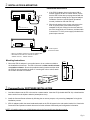
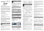
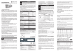
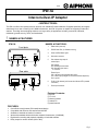
0211
IPW-1A
Intercom-Over-IP Adaptor
- INSTRUCTIONS The IPW-1A offers voice-quality Intercom function over standard IP based networks. Designed specifically to integrate
seamlessly into a new or existing LAN / WAN infrastructure, the IPW-1A system is capable of supporting hundreds of
stations. Providing intercom/paging solutions to a large variety of applications including commercial, industrial,
residential, general security, office, and institutional.
1 NAMES & FEATURES
IPW-1A
NAMES & FUNCTIONS:
Front plate
1
2
3
1.
Reset switch (reset unit)
2.
RS-232 Serial Port (for firmware recovery)
3.
Green and Red Status Lights
4.
Sub station connector
5.
Door release relay output &
external input.
Door release:
NC = Normally closed contact
NO = Normally open contact
C = Common
4
Rear plate
IN0 IN1
External input:
IN0 = call button input (simulates door call in)
IN1 = sensor input (changes icon in CommuniCenter adaptor list)
Gnd = ground
NO C NC
IN0 IN1
NC C NO
5
6.
RJ-45 10/100 ethernet jack & connection indicator LED’s (network
connection)
7.
Power input connector
PWR
6
7
Package Contents:
(1) IPW-1A
(1) PT-1211C
(1) Mounting hardware
(1) Software CD
(1) Install manual
FEATURES:
·
·
·
·
·
·
Cost-effective multi-master (PC-based) based design
Compatible with IE Series sub stations and AX-DM
Scalable to hundreds of stations / locations
Works with standard wired and wireless network infrastructure. (LAN/WAN)
Digital audio recording and playback capability via included software.
Relay output for remote release (N/O or N/C)
Pg. 1
2 INSTALLATION & MOUNTING
Installation Instructions:
POWER
IN0 IN1
PT-1211C
NO C NC
LAN
PWR
1. If the IPW-1A adaptor is not on the same LAN or
network segment as the PC master station, ensure
that the IPW-1A has been pre-programmed with the
proper connection settings prior to physical adaptor
installation. See the CommuniCenter Operations
manual (included on CD with IPW-1A).
2. Wire the sub station to the proper connector on the
IPW-1A, and connect to the network using the
standard RJ-45 jack. Wiring from the sub station to
the IPW-1A should be a 2-conductor, shielded cable.
Connect the PT-1211C power supply included to the
power input connector.
Note:
Contact rated at 30V, 1A.
PT
SUB
RESET
RS-232
STATUS
SUB
1
2
Audio Only Door
IE Series sub station
to sub station should be 2-conductor shielded cable.
* Wiring
Wire distance from IPW-1A to IE series sub station:
22AWG = 387 feet, 18AWG = 980 feet
Mounting Instructions:
1-5/8"
1. Mount the IPW-1A adaptor in a controlled area or in an enclosure suitable to
the installation environment. The IPW-1A chassis is neither vandal resistant
nor weather resistant. Secure the provided mounting bracket and then slide
the IPW-1A onto the bracket as shown. If mounting the unit on a shelf, attach
the 4 rubber feet that are included.
4-11/16"
4"
3 CommuniCenter SOFTWARE INSTALLATION
1. Load the software onto the PC to be used as a master station. Insert the CD (included with IPW-1A) or download the
latest version from the Aiphone website (www.aiphone.com).
2. Install the CommuniCenter software by following the on-screen prompts, or by executing “setup.exe” to begin the
installation process.
3. IPW-1A adaptors within the same broadcast domain as the PC will appear in the sub station location list. Consult the
CommuniCenter Operation manual document for further software functionality and configuration information.
NOTE – If installing system over a WAN please refer to the CommuniCenter Operation manual.
Pg. 2
4 STATION SET-UP
DHCP Enabled:
·
·
·
An IP address will automatically be assigned to each IPW-1A with the default ID# as 0 and Location Name left
blank.
Right click on each station to open the drop down box, and select Settings. This will open the Hardware
Configuration tool. Give each adaptor a unique ID# along with a unique Location Name.
It is recommended that a password be set for each adaptor. This password can be the same for all adaptors in the
LAN if you wish. To set the password, right click on the device and select Launch in browser. Under Security
Settings, enter a password of your choosing in the Set Password field and select Apply. Once set, this password
must be entered before any changes can be made in the Hardware Configuration tool, or web interface.
5 HARDWARE DIAGNOSTICS
RED and GREEN LEDs next to RS-232 Serial Port
Unit powering up:
· While the unit is searching for its IP address, the Red LED and Green LED will blink alternately. In the absence of a
DHCP server any network activity during this time should allow it to get an IP address, such as opening a web
browser.
· Upon finding its IP address, the IPW-1A will use SonicIP to verbally announce that address. At this time the Red
LED will blink.
· If an error is detected, the Red LED will remain on, then the Green LED will blink three or five times depending on
the error. Upon blinking the error message, the unit will reset itself. It will blink five times if the firmware is corrupt or
if there is an IP address conflict. It will blink three times if the network hardware could not be initialized, or if there is
a corrupt MAC address.
Pg. 3
Device running / normal operation:
· During normal operation, the Green LED will remain on while the Red LED will remain off.
Pushing the reset button:
· Upon pressing the reset button, the Green LED and Red LED will remain on. If the reset button is held for 10
seconds or more, the Green LED will remain lit and the Red LED will blink, resetting the unit to factory defaults.
Ethernet jack LED status
Yellow: link is established
Green: connected to 10Mbit network
Orange: connected to 100Mbit network
6 SPECIFCATIONS
Hardware Specifications:
Input Voltage:
Network Interface:
IP Assignment:
Hardware Protocols:
Use Aiphone PT-1211C (included); 15-24V AC/DC
10/100 Base-T Ethernet (Auto detection) RJ-45
Static or Dynamic
TCP/IP, UDP, DHCP, SNMP, AutoIP, SonicIP, Ipzator
Contact Aiphone for additional supported protocols
Transport Bandwidth: ≈128Kbps per active session (normal mode)
≈64Kbps per active session (low bandwidth mode)
Audio Encoding:
PCM (raw), G.7II (mLaw)
Audio Sampling:
16bit at 8kHz (normal mode)
8bit at 8kHz (low bandwidth mode)
Output Level:
Determined by sub station
Relay Contact Rating: 30V AC/DC 1.0A (resistive)
Operating temperature: 32°F to 104°F (0°C to 40°C)
Dimensions:
1-1/2″H x 4-1/4″W x 4-15/16″D
Software System Requirements:
For optimum performance of the CommuniCenter program, we recommend the following
minimum requirements:
Operating System:
Processor:
Memory:
Hard drive:
Sound Card:
®
®
Microsoft Windows XP (SP2), Windows Vista
1 GHz or faster
256MB of RAM
50MB of available disk space
Windows supported sound card (w/ speaker & microphone)
WARRANTY
Aiphone warrants its products to be free from defects in material and workmanship under normal use and service for a period of one year after
delivery to the ultimate user. We will repair free of charge or replace at no charge Aiphone product, that upon examination by an Aiphone Repair
Technician is proven defective and under warranty. Aiphone reserves the right to make the final decision whether there is a defect in materials and/or
workmanship; and whether or not the product is within the warranty.
This warranty covers bench repairs by the Aiphone Service Department only, and does not extend to units that have been repaired or altered outside
of the factory. Aiphone is not responsible for any costs incurred involving on-site service calls. This warranty shall not apply to any Aiphone product
that has been subjected to misuse, neglect, accident, power surge, or used in violation of instructions furnished.
Aiphone Communication Systems
1700 130th Ave. N.E.
Bellevue, WA 98005
(425) 455-0510
FAX (425) 455-0071
TOLL FREE TECHNICAL SUPPORT:
(800) 692-0200
E-MAIL: [email protected]
Pg. 4
IPW-1A Instr.
0211DM