1
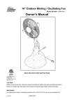
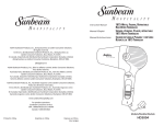
18” Misting / Oscillating Fan
Model Number: AM12MF18-1
Owner’s Manual
READ AND SAVE THESE INSTRUCTIONS
CAUTION:
Before using this product, read this manual and follow all safety rules and operating instructions.
Failure to comply with instructions could result in personal injury and/or property damage.
IMPORTANT:
For replacement parts or assembly questions go to www.auramist.com or call 1-‐800-‐320-‐6478.
Rev. 2/13
AM12MF18-1
1
Table of Contents
SECTION
PAGE
1. Safety Information …………….……………………………………………………….…….…….. 2
2. Carton Contents……………………………………………………………………….….…….…... 5
3. General Assembly Instructions ……………………………………….……………………....….. 6
4. Operation Instructions…………………………………….……………..……………..……....….. 7
5. Maintenance………………………………………………………………….………………....….. 9
6. Storage…………………………..…………………………………………….……………......…... 10
7. Troubleshooting…………………………..…………………………………….…………..…..……11
8. Exploded View........................................................................................................................ 12
9. Parts List… ……………………….……………………….….…………….................................. 13
10. Warranty ……………..……………………………………………….………...……………..…..... 14
Safety Warnings
READ AND SAVE THESE IMPORTANT SAFETY INSTRUCTIONS Household Type
SAVE THIS MANUAL FOR FUTURE REFERENCE.
READ ALL INSTRUCTIONS BEFORE USING THIS APPLIANCE.
Read and understand this instruction manual and all labels on the misting fan before using.
Safety is a combination of common sense, staying alert and knowing how this misting fan works. Use this
misting fan only as described in this manual. To reduce the risk of personal injury or damage to the
misting fan, use only recommended accessories.
Understanding Safety Terminology
DANGER: If safety information is not followed, someone will be seriously injured or killed.
WARNING: If safety information is not followed, someone could be seriously injured or killed.
CAUTION: If safety information is not followed someone may be injured.
Rev. 2/13
AM12MF18-1
2
When using this misting fan follow basic safety precautions including the following: WARNING: To reduce the risk of fire, electric shock, or injury:
1.
Make sure that the power source complies with the electrical requirements of the misting fan.
2.
Do not use this misting fan with any solid-state speed control device.
3.
Do not store outdoors. (See storage section)
4.
Do not use this misting fan with a damaged filter or without a filter installed.
5.
To reduce the risk of personal injury, the misting fan should not be used as a toy or placed where
children can reach it.
6.
Close supervision is necessary when any appliance is used near children.
7.
Use this misting fan only as described in this manual.
Any other use may cause electrical shock,
fire, injury to people or animals.
WARNING: DO NOT USE THE MISTING ON-OFF SWITCHES AS A MEANS OF
DISCONNECTING POWER WHEN INSTALLING OR SERVICING THIS PRODUCT.
ALWAYS DISCONNECT THE POWER CORD.
8. Disconnect the power cord before moving or performing any maintenance on the misting fan.
9. This misting fan shall not be used in potentially dangerous conditions, such as flammable,
explosive or chemically loaded atmospheres.
10. Do not use or store near hazardous materials.
11. Completely assemble the misting fan according to these instructions before connecting to the
power source.
12. If the misting fan is not working correctly, has missing parts, has been dropped, damaged or
dropped in water, call an authorized service center for evaluation, adjustment or repair.
WARNING: IMPROPER CONNECTION OF THE EQUIPMENT-GROUNDING
CONDUCTOR CAN RESULT IN A RISK OF ELECTRICAL SHOCK. CHECK WITH A
QUALIFIED ELECTRICIAN OR SERVICE PERSON IF YOU ARE IN DOUBT AS TO
WHETHER THE OUTLET IS PROPERLY GROUNDED. DO NOT MODIFY THE PLUG
PROVIDED WITH THE MISTING FAN IF IT WILL NOT FIT THE OUTLET; HAVE A
PROPER OUTLET INSTALLED BY A QUALIFIED ELECTRICIAN. DO NOT USE A
THREE-PRONG TO TWO-PRONG ADAPTER. IMPROPER CONNECTION MAY CREATE
A RISK FOR ELECTRICAL SHOCK.
13.
15.
To protect against a risk of fire, electric shock, or injury to persons, unplug or disconnect the
misting fan from the power supply before cleaning and user-maintenance, such as lubrication.
To protect against electrical shock, do not immerse unit, plug, or cord in water or spray with
liquids.
Keep the power cord away from heated surfaces.
16.
To reduce the risk of injury from the misting fan accidentally starting, unplug the power cord
14.
before replacing the filter.
17.
Do not leave the misting fan unattended when it is plugged in. Unplug it from the power outlet
when not in use and before servicing. Turn off the misting fan before unplugging.
18.
Do not operate the misting fan with a damaged power cord, plug, fuse or if the misting fan is
damaged in any manner.
Call an authorized service center for evaluation, adjustment or
repair.
Rev. 2/13
AM12MF18-1
3
19.
Do not run cord under carpets. Do not cover cord with throw rugs, runners, or similar
coverings. Do not route cord under furniture or appliances. Place power cord away from traffic
area and where it will not be tripped over.
20.
Do not insert or allow any foreign objects to enter the intake or exhaust air openings, as it may
cause mechanical, electrical, or fire damage to the mist fan.
21.
Do not block or tamper with the misting fan nozzles, as it may reduce or impede the functionality
or quality of the mist. Call an authorized service center for evaluation, adjustment or repair.
22.
Always place the misting fan on a stable flat surface to avoid the chance of tipping.
23.
Never place the misting fan where it may fall into a water reservoir (example: bathtub or pool),
or anything containing an electrical conductive substance.
24.
This product must be grounded. If it should malfunction or break down, grounding provides a
path of least resistance for electric current to reduce the risk of electric shock. This product is
equipped with a power cord having an equipment-grounding conductor and a grounding plug.
Plug into an appropriate outlet that is properly installed and grounded in accordance with all
local codes and ordinances.
25.
Avoid contact with moving parts.
26.
Do not hang or mount misting fan on a wall or ceiling.
27.
Do not operate without misting fan guards properly in place.
28.
Grasp plug and remove from the receptacle or other outlet device. Do not unplug by pulling on
power cord.
29.
Risk of fire. Do not replace attachment plug. Contains a safety device (fuse) that should not be
removed. Discard product if the attachment plug is damaged.
CAUTION:
DO NOT USE IN A WINDOW.
FAILURE TO DO SO COULD
RESULT IN THE PRODUCT COMING APART DURING OPERATION AND/OR
PERSONAL INJURY.
Rev. 2/13
AM12MF18-1
4
Carton Contents
Pack List
QTY.
1. Front fan guard assembly
1
2. Fan blade
1
3. Rear fan guard
1
4. Fan motor head assembly
1
5. Fan Pole
1
6. Water filter assembly
1
7. Air filter assembly
1
8. Power base assembly
1
9. Junction box cover
1
10. Filter Access Door
1
11. Power base pole
1
12. Screws ST3.9x16
16
13. Screws M5x16
2
Rev. 2/13
AM12MF18-1
5
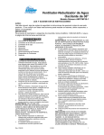
General Assembly Instructions
A Phillips head screwdriver is needed for assembly.
1. Ensure that the power cord is disconnected from the power outlet.
2. Insert power base pole through hole in the power base as illustrated, and fasten with the four 3.9x16
screws (fig. 1).
3. Align fan motor head to the fan pole hole as illustrated, and fasten the fan motor head to the fan pole
with the one M5x16 screw (fig. 2).
4. Align fan head & pole assembly to the power base assembly as illustrated, and press the fan head
assembly until the screw hole is aligned to the fan pole hole, fasten the fan pole assembly to the power
base assembly with one M5x16 screw (fig. 3).
5. Connect fan pole wire connector to power base wire connector (be sure to push connectors fully
together until locked). Fasten the junction box cover to the fan pole assembly with the four 3.9x16
screws (fig. 4).
6. Remove the protective covering and connect the air filter assembly and water filter assembly to the
connector on the power base assembly by pushing the tubes all the way into the corresponding
connectors (fig. 5).
7. Install filter access door to the fan pole assembly (fig 6).
8. Align the rear fan guard alignment hole to the alignment pin on the motor housing, and fasten the rear
Rev. 2/13
AM12MF18-1
6
fan guard to the fan motor head with four 3.9x16 screws (fig 7).
9. Mount the fan blade to the fan motor shaft. Make sure the fan blade screw aligns with the flat on the
motor shaft and tighten the fan blade screw which has already assembled in the fan blade (fig 8).
10. Align the front and rear guard and assemble together and secure with four 3.9x16 screws (fig 9).
11. Remove the protective covering and connect the air tube and water tube to the connectors on the front
of fan pole assembly by pushing the tubes all the way into the corresponding connectors. (Note, small
diameter tube = Water and large diameter tube = Air) (fig. 10).
Operating Instructions
IMPORTANT: Read this owner’s manual before operating this product.
Place the misting fan on a level surface near an electrical outlet.
Place the misting fan out of reach of
children. Do not insert anything into the fan guards. If moving the misting fan to a different location, turn it
OFF and unplug it from the socket.
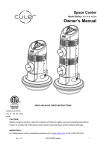
Testing the GFCI
1. Put the plug into the grounded outlet, the indicator light on the GFCI lights up (fig. 1).
2. Turn the motor on by flipping the switch to ON position ("I" "II" or "III"), press "TEST" button on the
GFCI, the light goes out and the unit stops working (fig. 2).
3. Then press "RESET" button on the GFCI, the indicator light lights up and the unit powers on
immediately (fig. 3).
• To operate the misting mist fan, plug the power cord into a 120 VAC, 60Hz outlet.
CAUTION: MISTING FAN AND/OR MISTING SYSTEM MAY START UP WHEN
THE UNIT IS INITIALLY PLUGGED INTO THE POWER OUTLET.
Rev. 2/13
AM12MF18-1
7
Fan Operation (ON-OFF, Speed control)
Press the button to Low, Med, High, or OFF to select fan speed (fig.1).
Fan Operation (Oscillation Control)
To activate the oscillation function, turn the switch on. To deactivate (stop) the oscillation function,
turn the switch off. The oscillation angle is approximately 90 degrees (fig. 2).
• Misting Operation
IMPORTANT: This product is designed to operate with clean water. The
misting fan and/or misting system may start up when the unit is initially plugged to
the power outlet.
IMPORTANT: BEFORE STARTING:
l Check to ensure the water tank drain cap is secure and fully tightened (Fig. 1).
l Please keep the mist fan 12 feet away from your furniture and other electrical appliances (fig. 2).
l Clean and clear any dirt or dust from the fan to prevent water contamination.
l Check that all water and air tube connections are secure.
l Remove fill cap on power base assembly and fill with CLEAN WATER through the basket filter until
tank is filled to approximately 1” below the bottom of the basket filter.
l Add ¼ teaspoon of unscented chlorine bleach to the water tank (approximately 5 drops per gallon of
clean water).
l Replace fill cap and hand tighten.
Misting ON/OFF control
Mist ON
1. Turn the mist control valve counter-clockwise to fully open (fig. 3).
2. Open and fill water tank (use clean water only), then lock the water cap. (important: Fully tighten tank
cap to ensure proper misting function)(fig. 4).
3. Press the rocker switch to the ON position (fig 5).
4. Once mist is visible, slowly close the mist control valve until desired mist is achieved, (refer to
ADJUSTING MIST DENSITY section, to get optimal mist performance) (fig. 6).
Rev. 2/13
AM12MF18-1
8
Mist OFF
1. Turn the pump switch to the OFF position when complete (fig. 7).
Note: Unit will continue to mist for a short time while the unit purges the pressure built up in the system.
ADJUSTING MIST DENSITY
CAUTION: Do not over tighten and/or loosen the water flow control valve.
The misting function of this fan is adjusted by turning the flow control valve on the fan pole assembly
clockwise to decrease mist density or counter-clockwise to increase mist density. It may take a minute for
misting to start. It is normal for air to come out of the nozzles before the misting begins.
To optimize the cooling effectiveness of the system, you can:
l Operate the unit with a DRY or WET mist, based on your needs.
l To increase the mist density (wetness), turn the mist control valve counter-clockwise.
l To decrease the mist density (dryness), turn the mist control valve clockwise.
Operating Tips
For dry climates, increasing the water flow will provide maximum cooling results. In humid climates, a
reduced water flow is recommended.
Maintenance
CUSTOMER RESPONSIBILITIES
Read and follow the maintenance schedule and the maintenance procedures listed in this section.
WARNING: ALWAYS UNPLUG THE POWER CORD BEFORE MOVING OR
SERVICING THE MISTING FAN.
WARNING: DO NOT IMMERSE THE MISTING MIST FAN IN WATER!
REPLACING FILTERS
WARNING:
ANY SERVICING OF THIS UNIT, EXCEPT FOR GENERAL
MAINTENANCE DESCRIBED IN THIS SECTION, SHOULD BE PERFORMED BY AN
AUTHORIZED SERVICE REPRESENTATIVE.
CAUTION:
Rev. 2/13
The filters have been designed to provide optimal system
AM12MF18-1
9
performance by catching any debris that may enter the supply lines throughout use.
Semi annual replacement of both the air and water filters ensures the life of your
system.
•
Remove the filter access door and locate the air and water filters (fig 1).
• The filters are connected to the system via “Push-In” connectors for ease of service
• Push the connector ring and pull out the air filter hose from the push-in connector, and the water
filter hose from the water flow control valve (figures 2 & 3).
• Dispose of old filter. Always dispose of waste according to local law.
• Remove filter from package and orient the directional arrow so that the flow direction is towards the
up (fig. 4).
• Push the hose into the push-in connectors to connect the filters (fig.4).
• Reinstall filter access door (fig.5).
REPLACE FUSE
WARNING: ALWAYS UNPLUG THE POWER CORD BEFORE REPLACE THE
FUSE.
• Open fuse cover. Slide open fuse access cover on top of attachment plug towards prongs (fig 1).
• Remove fuse carefully, use a proper tool (small screwdriver or similar tool) to take the fuse out of
the fuse holder (fig 2~ fig 3).
• Risk of fire. Replace fuse only with 5 Amp, 125Volt fuse (provided with product).
• Close fuse cover. Push cover closed so that all tabs latch (fig 4).
• NEVER PLACE FOREIGN OBJECT INTO FUSE HOLDER. THIS WILL VOID ANY WARRANTY
AND CAN CAUSE INJURY OR DEATH.
Storage
CAUTION:
DO NOT USE GASOLINE, THINNER, ALCOHOL, SOLVENTS OR
OTHER HARSH CLEANNERS OR CHEMICALS TO CLEAN THE FAN. THEY WILL
DAMAGE THE MISTING FAN.
• Clean the unit with a soft cloth and mild soap solution.
• Dry all parts completely.
• Store the misting fan in a clean and dry place.
EMPTYING WATER TANK
• Place misting fan on surface safe for to be water drained.
Rev. 2/13
AM12MF18-1
10
• Remove drain plug by turning counterclockwise.
• Allow tank to drain completely.
• Replace drain plug and hand tighten turning clockwise.
CLEANING BASKET FILTER
• Remove fill cap and remove basket filter.
• Rinse debris from filter with running water.
• Replace basket filter and fill cap.
CONDITIONING WATER TANK
Conditioning the water tank ensures that the cooling system will operate at optimal levels throughout the
life of the system. It is suggested that the tank be conditioned at an interval of every 4th filling or
once/month; whichever comes first.
• Completely drain water tank. (See Emptying Water Tank)
• Fill tank with CLEAN WATER. Be sure to always fill tank with basket filter in place.
• Add ¼ teaspoon of unscented chlorine bleach to the water tank (approximately 5 drops per gallon of
clean water).
• Replace cap and hand tighten.
• Run system for 5 minutes with a WET mist.
• The system is conditioned and ready for operation.
Troubleshooting
PROBLEM
Fan not running
CAUSE
CORRECTION
1. Power cord is not connected
1. Connect power cord
2. Switch is in the “OFF” position
2. Switch fan on high, medium, or low
Positions
3. The indicator light on the GFCI
is out
3. Press "RESET" button on the GFCI, if
the indicator light does not light up,
check whether the fuse needs to be
changed
Unit not misting
1. Misting switch is in off position
1. Turn misting switch on
2. Water tank is empty
2. Fill tank with clean water
3. Mist control valve in
3. Open valve (counter-clockwise)
the ”CLOSED” position
4. Water filter could be clogged
4. Replace water filter
5. Air tank leak
5. Tank fill cap is not tight
Water streaming
1. Air pump is not working
1. Turn on the mist ON/OFF switch
from nozzle
2. Air flow is low
2. Possible kinked air hose.
Check assembly to ensure hoses are
routed and installed correctly.
Change the intake filter of air pump.
Rev. 2/13
AM12MF18-1
11
3. Air filter needs replacement
3. Replace air filter
4. Air hose leaks
4. Check all hose connections for air leaks
5. Foreign object in nozzle
5. Order and replace nozzle
Mist is not balanced
1. Low water flow
1. Adjust the water flow control valve
on three nozzle
2. Water hose leaks
2. Turn off mist fan motor, and feel any air
leaks on hoses
3. Kinked water hose
3. Check assembly to ensure hoses are
routed installed correctly.
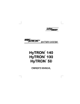
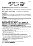
Exploded View
Rev. 2/13
AM12MF18-1
12
Parts List
No.
Part No.
1
AM12MF18R-1-001
Manifold Cover
1
2
AM12MF18R-1-002
Nozzle & Manifold assembly
1
3
AM12MF18R-1-003
Front Fan Guard
1
4
AM12MF18R-1-004
Fan Guard Hose Grommet
1
5
AM12MF18R-1-005
Fan blade
1
6
AM12MF18R-1-006
Rear Fan Guard
1
7
AM12MF18R-1-007
Fan Head Assembly
1
8
AM12MF18R-1-008
Button Switch Cover
1
9
AM12MF18R-1-009
Button Switches
1
10
AM12MF18R-1-010
Power Cord
1
11
AMMF16R-1-027
On/Off Switch
2
12
AM12MF18R-1-012
Junction Box Cover
1
13
AMMF16R-1-014
Air Pump
1
14
AMMF16R-1-013
Pump Bushings
4
15
AM12MF18R-1-015
Water filter assembly
1
16
AM12MF18R-1-016
Air filter assembly
1
17
AM12MF18R-1-017
Water tank assembly
1
18
AM12MF18R-1-018
Wheel
2
19
AM12MF18R-1-019
Wheel shaft
1
20
AM12MF18R-1-020
Base cover
1
21
AM12MF18R-1-021
Power Cord Strain Relief
1
22
AM12MF18R-1-022
Base Plate
1
23
AM12MF18R-1-023
Base Feet
6
24
AM12MF18R-1-024
Power Base Fan Pole
1
25
AM12MF18R-1-025
Water Tank Fill Cap
1
26
AM12MF18R-1-026
Water Tank Filter Basket
1
27
AM12MF18R-1-027
Filter Access Door
1
28
AMMF16R-1-004
Water Flow Control Valve
1
29
AM12MF18R-1-029
Junction Box Cover
1
101
AM12MF18R-1-101
Screws ST2.9×12C
4
102
AM12MF18R-1-102
Screws ST3.9x16
103
AM12MF18R-1-103
Screws M5x16
22
2
Rev. 2/13
Description
AM12MF18-1
QTY
13
Warranty
ONE FULL YEAR
WARRANTY
This product is warranted for one year from the date of purchase against defects in materials and
workmanship.
At our discretion, parts that prove to be defective will either be repaired or replaced, or the
whole product will be replaced. In either case, a copy of your proof of purchase will be required.
In case that any mechanical or electrical repairs are required during the warranty period, send your
complete product, postage or freight prepaid to the AURAMIST service center near you. Call the number
below to get the nearest service center.
This warranty does not include the air or water filters, which are expendable parts that can wear out from
normal use within the warranty period.
This warranty applies for only 90 days if this product is ever used
for commercial or rental purposes.
The serial number, model number and manufacturing date code can be found on the label attached to the
back of the power base assembly.
You should record these numbers and the date of purchase and keep in a safe place for future reference.
MODEL NUMBER:
XXXXX
MFG DATE CODE:
XXXX
SERIAL NUMBER:
XXXXXX
DATE OF PURCHASE:
XX-XX-XX
CUSTOMER SERVICE NUMBER: 1-800-320-6478
Website:
Rev. 2/13
www.auramist.com
AM12MF18-1
14