1
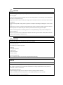
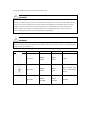
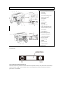
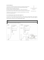
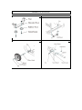
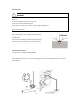
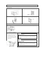
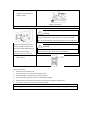
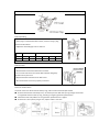
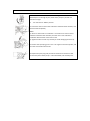
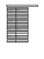
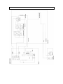
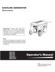
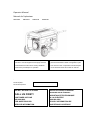
Operator Manual
Manuel de l’opérateur
MBG1200
MBG3500
MBG5500
MBG6500
IMPORTANT – Please make certain that persons
IMPORTANT - Prière de vous assurer que les
who are to use this equipment thoroughly read and
personnes destinées à utiliser cet appareil ont pris
understand these instructions and any additional
soin d'en lire et d'en comprendre le mode d'emploi
instructions provided prior to operation.
ou les directives avant de le mettre en marche.
.
Serial No/Year:
No De Sèire/Annèe
DO NOT RETURN TO STORE!
CALL US FIRST!
CUSTOMER HOTLINE
800-000-0000
FOR QUESTIONS OR
SERVICE INFORMATION
NE PAS RETOURNER AU MAGASIN!
APPELEZ–NOUS D’ABORD!
ASSISTANCE TELEPHONIQUE
A LA CLIENTELE
800-000-0000
POUR L'INFORMATION DE
QUESTIONS OU SERVICE
TABLE OF CONTENTS
SAFTEY INSTRUCTIONS
TOTAL WATTAGE, VOLTAGE AND INSTALLATION
FEATURES AND CONTROLS
PORTABILITY KIT INSTALLATION
BEFORE OPERATION
OPERATING THE GENERATOR
MAINTENANCE
STORAGE
TROUBLE SHOOTING
SPECIFICATION
WIRING DIAGRAM
EXPLODED DRAWING AND PARTS LIST
LIMITED WARRANTY
SAFTEY INSTRUCTIONS
DANGER
WARNING
CAUTION
DANGER indicates a potentially
WARNING indicates a potentially
CAUTION indicates a potentially
hazardous situation which, if not
hazardous situation which, if not
hazardous situation which, if not
avoided, WILL result in death or
avoided, could result in death or
avoided, may result in minor or
serious injury.
serious injury.
moderate personal injury, or
property damage.
WARNING
To reduce the risk of serious injury or even death, read the following safety precautions and operating
instructions before operating this generator.
DANGER
Using a generator indoors WILL KILL YOU IN MINUTES.
■ Generator exhaust contains carbon monoxide. This is a poison you cannot see or smell.
■ NEVER use inside a home or garage, even IF doors and windows are open; only use
OUTSIDE and far away from windows, doors and vents.
DANGER
FUEL IS HIGHLY FLAMMABLE AND EXPLOSIVE
■ Always turn off the engine before adding fuel. Hot engine parts, sparks or cigarettes can ignite
gasoline. Store fuel away from generator.
■ Never refuel while smoking or in the vicinity of an open flame.
■ Take care not to spill any fuel on the engine or muffler when refueling.
■ Before transporting the generator in a vehicle, drain all fuel to prevent leakage that may occur.
■ Store the generator in a well ventilated area with the fuel tank empty.
DANGER
ELECTRICAL SHOCK
■ Never operate the generator in rain, in wet or damp locations, or with wet hands, a serve
electrical shock may occur causing serious injury.
■ Generator should not be operated or stored in wet or damp conditions or on highly conductive
locations such as metal decking and steel work.
■ Always make sure the generator is properly grounded before operating. Failure to do so may
result in serious injury.
WARNING
ENGINE AND MUFFLER MAY BE HOT
Contact with muffler area can result in serious burns.
Exhaust heat/gases can ignite combustibles, structures or damage fuel tank causing a fire.
■ DO NOT touch hot parts and AVOID hot exhaust gases.
■ Allow equipment to cool before touching.
U.S. Code of Federal Regulation (CFR) Title 36 Parks, Forests, and Public Property require equipment powered by
an internal combustion engine to have a spark arrester, maintained in effective working order, complying to
USDA Forest service standard 5100-1C or later revision. In the State of California a spark arrester is required
under section 4442 of the California Public resources code. Other states may have similar laws.
WARNING
Starter and other rotating parts can entangle hands, hair, clothing, or accessories.
■
Do not wear loose clothing, jewelry, or anything that may be caught in the
starter or other rotating parts.
■
Tie up long hair when operating the generator.
WARNING
KEEP CHILDREN AND PETS AWAY
Keep bystanders, especially children and pets, at least 50 feet (15m) from the
generator. Do not let children touch the generator. When not in use, the generator
should be stored in a dry, locked location, out of reach of children.
CAUTION
HEAVY LOAD
Use proper lifting techniques when transporting the generator from site to site. Improper
lifting techniques may result in personal injury.
CAUTION
Improper treatment of generator can damage it and shorten its life.
To prevent surging that may possibly damage equipment, do not allow engine to run out of fuel when electrical
loads are applied.
Do not stick anything through ventilating slots, even when the generator is not operating. This can damage the
generator or cause personal injury.
The generator will do a better and safer job and give you much better service if it is used at the rate for which it
was designed.
■ Load must be kept within rating stated on generator nameplate. Overloading will damage the unit or shorten
its life.
■ Engine must not be run at excessive speeds. Operating an engine at excessive speeds increases the hazard of
personal injury. Do not tamper with parts which may increase or decrease the governed speed
Do not connect the generator to another generator to use in parallel. Doing so may result in damage to the
internal components.
Extension cords, power cords, and all electrical equipment must be in good condition. Never operate electrical
equipment with damaged or defective cords.
CAUTION
Your generator should never be operated under these conditions.
a. Uncontrolled change in engine speed.
b. Electrical output loss.
c. Overheating in connected equipment.
d. Sparking.
e. Damaged receptacles.
f. Engine misfire.
g. Excessive vibration.
h. Flame or smoke.
i. Enclosed compartment.
j. Rain or inclement weather. Do not let the unit get wet when operating.
NOTICE
Engine oil is hazardous to the environment.
Be very careful when changing your oil or working with oil not to spill it onto the ground. Even if it is washed
away, it will not mix with water and will pollute the watershed—having a negative effect on the plants and
animals that it comes in contact with.
When disposing of engine oil:
1. While changing the engine oil, place a drip pan under the oil plug to collect the waste.
2. Soak up any spills with sawdust, kitty litter, or sand. NEVER dump down the drain or sewer.
3. Take the oil and filter to an oil recycling center.
TOTAL WATTAGE, VOLTAGE AND INSTALLATION
Total Wattage
In order to prevent overloading and possible damage to your generator it is necessary to know the total wattage
of the connected load. To determine which tools and/or appliances your generator will run follow these steps:
1. Determine if you want to run one item or multiple items simultaneously.
2. Check wattage requirements for the items you will be running by referring to the load’s nameplate or by
calculating it (multiply amps x volts = watts).
3. Total the watts for each item. If the nameplate only gives volts and amps, multiply volts x amps = watts. 1 KW =
1,000 watts.
4. Motorized appliances or tools require more than their rated wattage for start up.
NOTE: Allow 2 1/2 to 4 times the listed wattage for starting equipment powered by electric motors.
5. The generator’s rated watts should match or exceed the total number of watts required for the equipment you
want to run.
6. Always connect the heaviest load to the generator first, then add other items one at a time.
Voltage
WARNING
Operating voltage and frequency requirement of all electronic equipment should be checked prior to plugging
them into this generator. Damage may result if the equipment is not designed to operate within a +/- 10%
voltage variation, and +/- 3 hz frequency variation from the generator name plate ratings. To avoid damage,
always have an additional load plugged into the generator if solid state equipment (such as a television set) is
used. A power line conditioner is recommended for some solid state applications.
A power line conditioner should be used when running one or more of the following solid state items:
Garage door openers, Kitchen appliances with digital displays, Televisions, Stereos, Personal computers, Quartz
clocks, Copy machines, Telephone equipment, and other solid state equipment may require a power line
conditioner.
Installation
WARNING
To avoid possible personal injury or equipment damage, a registered electrician or an authorized service
representative should perform installation and all service. Under no circumstances should an unqualified person
attempt to wire into a utility circuit.
To avoid backfeeding into utility systems, isolation of the residence electrical system is required.
Before temporary connection of the generator to the residence electrical system, turn off the main
service/disconnect.
If your generator is to be used as a stand-by power source in case of utility power failure, it should be installed by
a registered electrician and in compliance with all applicable local electrical codes.
Proper use requires that a double throw transfer switch be installed by a licensed qualified electrician so that the
building's electrical circuits may be safely switched between utility power and the generator's output, thereby
preventing backfeed into the power utility's electrical system.
WARNING
To avoid backfeeding into utility systems, isolation of the residence electrical system is required. Before
temporary connection of a generator to the residence electrical system turn off the main switch. Before making
permanent connections a double throw transfer switch must be installed. To avoid electrocution or property
damage, only a trained electrician should connect generator to residence electrical system. California law
requires isolation of the residence electrical system before connecting a generator to residence electrical
systems. Temporary connection not recommended due to backfeeding.
Always follow local codes and regulations that apply to the installation of any item that concerns this product.
WARNING
To avoid possible personal injury or equipment damage, a registered electrician or an authorized service
representative should perform installation and all service. Under no circumstances should an unqualified person
attempt to wire into a utility circuit.
Style
Ampere
Up to 20A
Up to 20A
Up to 30A
Receptacle
AC Plug
NEMA
NEMA
5-20R
5-20P
NEMA
NEMA
5-20R
5-20P
NEMA
NEMA
L14-30R
L14-30P
Description
Duplex
GFCI (Ground Fault
Circuit
duplex
Twistlock
Interrupter),
FEATURES AND CONTROLS
1.
Fuel Tank Cap
2.
Fuel Tank
3.
Fuel Gauge
4.
Fuel Tank Breathing Valve
5.
Engine Choke Lever
6.
Fuel Shut-off
7.
Air Filter
8.
Recoil Starter
9.
Oil Gauge
10. Engine Shut-off
11. 120 V, 20 Ampere Duplex
Receptacle(GFCI optional)
12. AC Protector
13. Circuit Breaker
13a. Hour Meter(optional)
14. 120/240 V, 20 Ampere
Twistlock Receptacle
15. Ground Terminal
16. Oil Drain Plug
17. Muffler
18. Spark Arrester
19. Carbon Canister
20. Spark Plug
Fuel Gauge (3)
120 V, 20 Ampere Duplex Receptacle (11)
20 amps of current may be drawn from each half of the receptacle. However, total power drawn must be kept
within nameplate ratings. These receptacles may be used along with the twistlock receptacle provided the
generator is not overloaded.
120V, 20 Ampere GFCI Duplex Receptacle(optional)
If your generator comes with GFCI duplex receptacle, please follow below step:
After starting the engine, check the GFCI for proper functioning by the following test
procedure.
■ Push TEST button, The RESET button will pop out. Power is now off at the outlets
protected by the GFCI, indicating that the device is functioning properly.
■ If TRIP does not appear when testing, do not use the generator. Call a qualified
electrician.
■ To restore power, push RESET button.
WARNING
If the RESET button pops out during operation, stop the generator immediately and call a qualified electrician for
checking generator and the appliances.
AC Protector and Circuit Breaker (12 and 13)
Your generator is protected by an AC protector (expect MBG3500)
and circuit breaker. If the generator is overloaded or an external short
circuit occurs, the AC protector or circuit breaker will trip. If this
occurs, disconnect all electrical loads and try to determine the cause
of the problem before attempting to use the generator again. If
AC Protector
overloading causes the AC protector and circuit breaker to trip,
reduce the load.
NOTICE
Continuous tripping of the AC protector or circuit
breaker may cause damage to generator or
equipment.
120/240 V, 30 Ampere Twistlock Receptacle (14)
A maximum of 30 amps may be drawn from the 120/240
volt receptacle, provided it is the only receptacle used.
However, current must be limited to the nameplate
rating. If the 120/240 volt receptacle is used along with
the 120 volt receptacle, the total load drawn must not
exceed the nameplate ratings.
Circuit Breaker
Ground Terminal (15)
Your generator needed to be properly connected to an appropriate earth ground to
help prevent electric shock. A ground terminal connected to the frame of the
generator has been provided for this purpose.
Connecting a length of heavy gauge (12 AWG min.) copper wire between the
generator Ground Terminal and a copper rod driven into the ground should provide a
GROUND TERMINAL LOCATION:
suitable ground connection. However, consult with a local electrician to insure that
local codes are being adhered to.
Fuel Tank Breathing Valve (4) & Carbon Canister (19) for U.S.
Your generator may be equipped with breathing valve and carbon canister required by Section 213 of the Clean
Air Act (42 U.S.C. section 7547), 40 CFR Part 90, 40 CFR Part 1054, 40 CFR Part 1045 or 40 CFR Part 1060 and
California Health and Safety Code, Section 39600, 39601and 43013.
NOTICE
This is a system to control gasoline evaporative emission. Do not remove the hose, breathing valve and
carbon canister when there is fuel in the fuel tank
PORTABILITY KIT INSTALLATION
Step 1
Step 2
Step 3
Step 4
.
BEFORE OPERATION
Check Engine Oil
WARNING
DO NOT attempt to start this engine without filling the crank case with the proper amount and type of oil. Your
generator has been shipped from the factory without oil in the crankcase. Operating the unit without oil can
damage the engine.
Use class SE oil or a higher grade according to the table below. SAE 10W-30 or 10W-40 is recommended for
general, all temperature use.
-
Inspect the oil level by using the oil gauge before
starting the engine each time;
-
Top up the oil level to the maximum level mark
and/or until oil flows from the opening.
-
Ensure both Oil Gauges are secure.
LOW OIL SENSOR
The unit is equipped with a low oil sensor. If the oil level becomes lower than required, the sensor will activate a
warning device or stop the engine.
If generator shuts off and the oil level is within specifications, check to see if generator is sitting at an angle that
forces oil to shift. Place on an even surface to correct this.
If engine fails to start, the oil level may not be sufficient to deactivate low oil level switch. Make sure the sump is
completely full of oil.
Check Engine Fuel
WARNING
DO NOT refuel while smoking or near open flame or other such potential fire hazards. Otherwise fire accident
may occur.
- Do not refill tank while engine is running or hot.
- Close fuel cock before refueling with fuel.
- Be careful not to admit dust, dirt, water or other foreign objects into fuel.
- Wipe off spilt fuel thoroughly before starting engine.
- Keep open flames away.
Fill the tank with clean, fresh unleaded automotive gasoline
- Check fuel level.
- If fuel level is low, refill with unleaded automotive gasoline.
- Be sure to use the fuel filter screen on the fuel filter neck.
Check Air Filter If It Is Clean
If not, please refer to “HOW-TO” MAINTENANCE.
Check Loose and Missing Parts
Before starting the generator, check for loose or missing parts and for any damage which may have occurred
during shipment.
Check the generator if it is correctly ground
OPERATING THE GENERATOR
Start the Generator
1.
Disconnect all electrical loads from the generator
2.
Set the circuit breaker to the “OFF” position.
3.
Open the fuel shut off valve
4.
Set the engine stop switch to the “ON” position.
5.
Adjust choke lever
Set the choke lever to “Choke” positon. Not necessary if the engine is warm
6.
Pull the starter handle slowly until
resistance is felt. This is the
“compression” point. Then,
return the handle to its original
position and pull swiftly until
WARNING
To avoid accidently hurting people nearby when pulling the
starter handle, Please keep bystanders, especially children and
pets, away
engine starts.
CAUTION
Do not allow the starter handle to snap back against the engine.
Return it gently to its starting position to prevent damage to the
starter or the housing.
7.
As the engine warms up,
readjust the choke lever to
“OPEN” postion
8.
Connect the load
CAUTION
When applying a load, do not exceed the maximum wattage
rating of the generator when using one or more receptacles.
Also, do not exceed the amperage rating of any one receptacle.
Apply load only after generator is
running. Voltage is regulated via
CAUTION
the engine speed adjusted at the
Do not apply heavy electrical load during break-in
factory for correct output.
period (the first two to three hours of operations).
Readjusting will void warranty.
9.
Set the circuit breaker to the
“ON” position.
Stop the Generator
1.
Remove entire electrical load.
2.
Let the engine run for two minutes without load.
3.
Move the engine stop switch to the “OFF” position.
4.
Do not leave the generator until it has completely stopped.
5.
Close the fuel shut off valve if the engine is to be put in storage or transported.
6.
If a cover is used, do not install until unit has cooled.
NOTICE
Move the engine stop switch to the “OFF” position to stop engine directly in an emergency situation.
MAINTENANCE
1.
Maintenance Schedule
ITEM
REMARKS
Spark Plug
Engine Oil
INITIAL
EVERY
EVERY
Before Operation
25HR
50HR
100HR
Check condition adjust gap and clean. Replace if
●
necessary
Check oil level
●
Replace
●
Air Filter
Clean, replace if necessary
Fuel Filter
Clean and adjust. Replace if necessary
Fuel Hose
DAILY
●
●
Check fuel hose for crack or damage. Replace if
●
necessary
Check for leakage. Retighten or
Exhaust
replace gasket if necessary
System
Check muffler screen. Clean/replace if
●
●
necessary
Carburetor
Cooling
System
Starting
System
check choke operation
●
●
Check fan damage
●
Check recoil starter operation
●
Fittings
Check all fittings and
Fasteners
fasteners correct if necessary
●
CAUTION
To prevent accidental starting, always remove the spark plug or cable from the spark plug before
maintaining the generator or engine.
2.
“How-To” Maintenance
Engine Oil Change
a.
Drain oil by removing the drain plug and the oil gauge while engine is warm.
WARNING
Engine oil may be hot.
b.
Reinstall the drain plug and fill the engine with oil until it reaches the upper level on the oil filler
cap.
c.
Clean the oil on the panel. Dispose of used oil in local authority disposal site.
Clean Spark Plug
a. If the plug is contaminated with carbon, remove it using a plug
cleaner and wire brush.
b. Adjust the electrode gap to 0.7 to 0.8 mm.
Engine
GT241/400/600
GT1000/GT1300
Manufacturer
NGK
NHSP
NGK
Denso
Champion
Bosch
Product No.
BP6RSH
E6RTC
BPR5ES
W16EPR
RN11YC
WR8DC+
Clean Air Filter
a. Unscrew the air filter cover.
b. Remove filter element and wash well in solvent.
c. Pour a small amount of oil onto the filter element and gently
squeeze out any excess oil.
d. Replace the filter element and air filter cover.
e. Be sure the filter cover seals properly all around.
Check the Carbon Brush
The brush is the area which touches the slip ring, and its surface must be kept smooth.
■ If the brush becomes excessively worn, its contact pressure with the slip ring changes and causes
a roughened surface on the slip ring, resulting in irregular generator performance.
■ Check the brush every 300 hours or if generator performance is irregular.
■ If the brush is 0.2 in (5mm) long or less, replace it with a new one.
STORAGE
Besides drain fuel from fuel tank, the following procedures should be
followed prior to storage of your petrol water pump for periods of 3
months or longer.
1.
Turn fuel cock to “OPEN” position.
2. Loosen the drain screw on the side of the carburetor float chamber, and
drain the fuel completely.
NOTE
1) There are two screws on carburetor. The vertical one is the screw to
hold the carburetor float chamber; the other one on the side of the
carburetor float chamber is the drain screw.
2) Tighten the drain screw very carefully to avoid damaging the fuel cup.
3. Remove the spark plug, pour 2 to 3 cc of engine oil into the cylinder, and
turn the crank shaft several times.
4. Replace the spark plug and pull starter handle until resistance is felt.
5. Store the petrol water pump in a well ventilated, low humidity area.
TROUBLE SHOOTING
NOTICE
If your generator experiences a low engine oil condition, the engine will automatically shut off. Please
check the oil first if you cannot start the generator.
Condition
Cause
Insufficient
compression
Corrective Action
Loose spark plug
Tighten plug properly
Loose cylinder head bolt
Tighten bolt properly
Damaged gasket
Replace gasket
1. Insufficient pulling speed for
Pull rope sharply
No fuel
starting rope
supplied to
2. Foreign matter in fuel tank
Clean tank
Engine won't
combustion
3. Clogged fuel line
Clean fuel line
start
chamber
4. No fuel in tank
Refill tank
5. Fuel switch not open
Open valve
1. Spark plug dirty with carbon
Remove carbon or wipe out spark
Combustion
or wet with fuel
plug
chamber
2. Damaged spark plug
Replace spark plug
supplied with
3. Faulty Magneto
fuel
4. Improper adjustment of
Low engine
output
Sufficient
Engine runs
compression
erratically
Consult dealer
carburetor
Improper grade of fuel used
Engine ON, yet
no AC output
Make sure the proper grade of fuel
has been used
Overloading
Make sure you haven’t plugged in too
Overheating
many devices. Check fan
Lower oil level
Add sufficient oil as specified.
Tripped circuit breaker
Reset
Poor connection or faulty lead
Check and repair
Broken receptacle
Faulty circuit breaker
Contact us
Generator problem
Low Temperature Starting
Generally, most gas powered generators have increased difficulty in starting during cold
temperatures. Ease of starting improves if the generator has been stored under more temperate
conditions such as in a garage or basement.
CAUTION
The generator should not be stored in such locations unless all fuel has been drained from the unit.
Please see ‘STORAGE’ within this manual for further instruction.
When starting the generator at a temperature below freezing the following steps are recommended:
-
Engine oil is to 5W-30 4-stroke formulation (low temperature oil) instead of 10W-30 oil.
-
Pull the starter cord briskly 3 times, and then wait 15 seconds if the engine does not start. The
delay of 15-seconds allows excessive fuel in the spark plug to vaporize. Failure to delay for
15-seconds pulling more than 3-times at one time may cause the spark plug to become flooded. If
the spark plug becomes saturated with fuel, the engine will not start.
-
If the engine does not start after many pulls, check the spark plug. If the spark plug is saturated
with fuel and/or carbon deposits, clean or replace with a clean spark plug.
SPECIFICATION
MODEL NO.
MBG1200
SERIAL NO.
MBG12AAC
Emission Certification
EPA Phase II
Evaporation Certification
None
Alternator
Type/Voltage regulation:
Brush/AVR
Frequency:
60 Hz
Voltage:
120 V
Rated Watts:
950 W
Starting Watts:
1200 W
Engine
Brand:
MITSUBISHI
Engine Model NO.:
GT241
Type:
OHV, 4 Stroke, Air cooled
Displacement:
79.6 cc
Fuel Tank Size:
1.85 Gallon/Unleaded Gasoline
Lubricating oil:
.1 Gallon/Engine oil SD or Higher
Starting System:
Manual Start
Oil Alert:
Equipped
Fuel Gauge:
Equipped
Control Panel
120V Duplex Outlet:
Equipped (×1)
*120V GFCI Duplex Outlet
-
120V/240V Twistlock
Outlet:
-
AC Protector
Equipped
Circuit Breaker:
None
*Hour Meter
Optional
Overview
Weight:
60.6 Lbs. (27.5 kilograms)
Dimensions:
18.5''L×14.9'' W×15.4'' H
MODEL NO.
MBG3500
SERIAL NO.
MBG35CAA
MBG35CAB
MBG35CAC
Emission Certification
EPA Phase III
CARB
EPA Phase II
49 states
California
None
Evaporation Certification
Alternator
Type/Voltage regulation:
Frequency:
Voltage:
Brush/AVR
60 Hz
120/240 V
Rated Watts:
2800 W
Starting Watts:
3500 W
Engine
Brand:
Engine Model NO.:
Type:
MITSUBISHI
GT600
OHV, 4 Stroke, Air cooled
Displacement:
182 cc
Fuel Tank Size:
4 Gallon/Unleaded Gasoline
Lubricating oil:
.16 Gallon/Engine oil SD or Higher
Starting System:
Manual Start
Oil Alert:
Equipped
Fuel Gauge:
Equipped
Control Panel
120V Duplex Outlet:
*120V GFCI Duplex Outlet
120V/240V Twistlock
Outlet:
AC Protector
Equipped (×2)
Optional
Equipped (×1)
None
Circuit Breaker:
Equipped
*Hour Meter
Optional
Overview
Weight:
Dimensions:
99 Lbs. (45 kilograms)
22.6'' L×17.3'' W×18.9'' H
MODEL NO.
MBG5500
SERIAL NO.
MBG55CAA
MBG55CAB
MBG55CAC
Emission Certification
EPA Phase III
CARB
EPA Phase II
49 states
California
None
Evaporation Certification
Alternator
Type/Voltage regulation:
Frequency:
Voltage:
Brush/AVR
60 Hz
120/240 V
Rated Watts:
5000 W
Starting Watts:
5500 W
Engine
Brand:
Engine Model NO.:
Type:
MITSUBISHI
GT1000
OHV, 4 Stroke, Air cooled
Displacement:
297 cc
Fuel Tank Size:
7 Gallon/Unleaded Gasoline
Lubricating oil:
.32 Gallon/Engine oil SD or Higher
Starting System:
Manual Start
Oil Alert:
Equipped
Fuel Gauge:
Equipped
Control Panel
120V Duplex Outlet:
*120V GFCI Duplex Outlet
120V/240V Twistlock
Outlet:
Equipped (×2)
Optional
Equipped (×1)
AC Protector
Equipped
Circuit Breaker:
Equipped
*Hour Meter
Optional
Overview
Weight:
174 Lbs. (79 kilograms)
Dimensions:
28.5'' L×20'' W×22.5'' H
MODEL NO.
MBG6500
SERIAL NO.
MBG65CAA
MBG65CAB
MBG65CAC
Emission Certification
EPA Phase III
CARB
EPA Phase II
49 states
California
None
Evaporation Certification
Alternator
Type/Voltage regulation:
Brush/AVR
Frequency:
Voltage:
60 Hz
120/240 V
Rated Watts:
6000 W
Starting Watts:
7000 W
Engine
Brand:
MITSUBISHI
Engine Model NO.:
Type:
GT1300
OHV, 4 Stroke, Air cooled
Displacement:
391 cc
Fuel Tank Size:
7 Gallon/Unleaded Gasoline
Lubricating oil:
.32 Gallon/Engine oil SD or Higher
Starting System:
Manual Start
Oil Alert:
Equipped
Fuel Gauge:
Equipped
Control Panel
120V Duplex Outlet:
*120V GFCI Duplex Outlet
120V/240V Twistlock
Outlet:
Equipped (×2)
Optional
Equipped (×1)
AC Protector
Equipped
Circuit Breaker:
Equipped
*Hour Meter
Optional
Overview
Weight:
Dimensions:
187 Lbs.
(85 kilograms)
28.5'' L×20'' W×22.5'' H
WIRING DIAGRAM
EXPLODED DRAWING AND PARTS LIST
LIMITED WARRANTY
This Mitsubishi engine product carries a guarantee of 24 months. If your product develops a fault
within this period, DO NOT return to store, you should, in the first instance contact our customer
service.
Not Covered:
-
Transportation charges for sending the product to the Company or its authorized service
representative for warranty service, or for shipping repaired or replacement products back to the
customer; these charges must be borne by the customer.
-
If a separate operator's manual and engine warranty from the engine manufacturer is included
with this product, only that warranty will apply to the engine.
-
Damages caused by abuse or accident, and the effects of corrosion, erosion and normal wear and
tear.
-
Warranty is voided if the customer fails to install, maintain and operate the product in
accordance with the instructions and recommendations of the Company set forth in the owner's
manual, or if the product is used as rental equipment.
-
The Company will not pay for repairs or adjustments to the product, or for any costs or labor,
performed without the Company's prior authorization.
Warranty Period: Two (2) years from the date of purchase on products used solely for consumer
applications; if a product is used for business or commercial applications, the warranty period will be
limited to one (1) year from the date of purchase. For warranty service, the customer must provide
dated proof of purchase
EMISSION SYSTEM WARRANTY
The following are specific provisions relative to your Emission Control Defects Warranty Coverage. It is
in addition to our engine warranty for non-regulated engines found in the Owner's Manual.
1. Warranted parts
Coverage under this warranty extends only to the parts listed below (the emission control system
parts) to the extent these parts were present on the engine purchased.
a. Carburetor
b. Air Induction System
• Air Cleaner
c. Ignition System
• Spark plug(s)
• Magneto ignition system
d. Catalyst system
• Exhaust manifold, if applicable
e. Miscellaneous Items Used in Above Systems
• Hoses, connectors, and assemblies.
2. Length of coverage
We warrant to the initial owner and each subsequent purchaser that the Warranted Parts shall be
free from defects in materials and workmanship which causes the failure of the Warranted parts for a
period of two years from the date the engine is delivered to a retail purchaser.
3. No charge
Repair or replacement of any Warranted Part will be performed at no charge to the owner, including
diagnostic labor which leads to the determination that a Warranted Part is defective, if the diagnostic
work is performed at our repair network
4. Claims and coverage exclusions
Warranty claims shall be filed in accordance with the provisions of our engine warranty policy.
Warranty coverage shall be excluded for failures of Warranted Parts which are not original Mitsubishi
parts or because of abuse, neglect or improper maintenance as set forth in our engine warranty policy.
We are not liable to cover failures of warranted parts caused by the use of add-on, non-original, or
modified parts.
5. Maintenance
Any warranted part which is not scheduled for replacement as required maintenance or which is
scheduled only for regular inspection to the effect of "Repair or replace as necessary" shall be
warranted as to defects for the warranted period. Any warranty part which is scheduled for
replacement as required maintenance shall be warranted as to defects only for the period of time up
to the first scheduled replacement for that part. Any replacement part that is equivalent in
performance and durability may be used in the performance of any maintenance or repairs. The
owner is responsible for the performance of all required maintenance, as defined in the our owner's
manual.
6. Consequential coverage
Coverage hereunder shall extend to the failure of any engine components caused by the failure of any
warranted part still under warranty.
SERVICE INFORMATION
CONTACT
1-800-000-0000
to find out closest repair center,
to obtain warranty service information
or to order replacement parts or accessories.
HOW TO ORDER REPLACEMENT PARTS
To order replacement parts, please give the following us information:
1. Model No. and Serial No. and all specifications shown on the Model No./Serial No. plate.
2. Part number or numbers as shown in the Parts List section.
3. A brief description of the trouble with the generator.