1
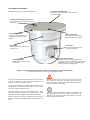
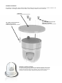
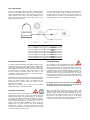
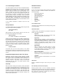
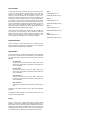
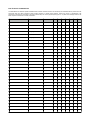
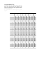
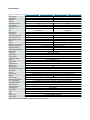
USER GUIDE
216/316
Contents:
PAGE! SECTION !
3!
3!
3!
3!
3!
4!
5!
6!
6!
6!
6!
6!
7!
9!
9!
9!
9!
10!
12!
14!
15!
16!
1.01!
1.02!
1.03!
1.04!
1.05!
2.01!
3.01!
4.01!
4.02!
4.03!
4.04!
4.05!
5.01!
6.01!
6.02!
6.03!
6.04!
7.01!
8.01!
9.01!
10.01!
-!
!
!
!
!
!
!
!
!
!
!
!
!
!
!
!
!
!
!
!
!
!
!
INTRODUCTION
MANUAL VALIDITY
DETECTION RANGES
CONVENTIONS
IMPORTANT WARRANTY INFORMATION
WARNINGS & IMPORTANT PRODUCT INFORMATION
TYPICAL SYSTEM EXAMPLES
CAMERA CONTROL DATA
CABLING REQUIREMENTS
SETTING CAMERA ADDRESS
INSTALLATION CONSIDERATIONS
PROTOCOL INFORMATION
HARDWARE INSTALLATION
CONNECTIONS
VIDEO CONNECTIONS
DATA CONNECTIONS
POWERING UP
CONTROLLING THE CAMERA
PROTOCOL LIST
CAMERA ADDRESS TABLE
SPECIFICATIONS
BACK COVER / CONTACT DETAILS
1.01 Introduction
1.03 Detection Ranges
IRIS216 and IRIS316 Thermal Imaging PTZ cameras convert
heat emitted and reflected from objects into a detailed visual
image. This means they can be used to provide visibility in
absolute zero light conditions.
Based on NATO criteria for Human and Typical Vessel targets.
Actual range may vary depending on camera set up,
environmental conditions, user experience and type of monitor
or display used.
They provide an incredibly powerful method to help navigate at
night and in low light or poor visibility conditions. Any changes in
temperature greater then 50mK are detected, meaning it's
possible to observe reflections of objects, footprints after a
person has left the area or even the texture of snow and ice.
Model
A powerful sensor known as a Micro-bolometer picks up the long
range infra red waveforms omitted and reflected by all objects
and converts them into electrical signals which are used to build
up a visual screen. The amount of pixels on the sensor and their
proximity to each other determine the sensitivity of the unit and
the resolution of the picture. The IRIS216 has a 384x288
resolution and the IRIS316 has a 640x480 resolution. The
IRIS216 is referred to as a QVGA resolution, although in fact it
has 44% more pixels than a standard QGVA image. The
IRIS316 is referred to as a VGA camera. Both cameras have a
pixel pitch of 17µm.
Iris thermal imaging cameras are perfect additions to both
leisure marine and commercial marine navigational and
situational awareness set-ups. They are also used widely by the
military and emergency services. Iris Thermal cameras are
feature rich, high quality situational awareness and night vision
tools. Because the wavelengths used are twenty times longer
than the wavelengths in the visible part of the spectrum, the
radiation undergoes less scattering by particles in the
atmosphere and as a result, visibility through smoke, mist and
fog can also be improved.
IRIS216
IRIS316
Resolution & Pitch 384x288~25micron 640x480~17micron
Focal Length
HFOV
18.5mm
25mm
29.1˚
24.6˚
1.8m H x 0.5m W
1.8m H x 0.5m W
Detection
454 Meters
897 Meters
Recognition
114 Meters
224 Meters
Identification
57 Meters
112 Meters
Boat / Vehicle
2.3m H x 2.3m W
2.3m H x 2.3m W
Detection
1289 Meters
2546 Meters
Recognition
322 Meters
637 Meters
Identification
161 Meters
318 Meters
Person
1.04 Important Warranty Information.
This product is covered by a 1 year return to base warranty valid
from date of purchase. To qualify for an additional year warranty
free of charge beginning at the end of the original warranty
period and learn more about the terms and conditions of the
warranty, register your product at www.boat-cameras.com
Iris Innovations range of Thermal Imaging cameras employ
cutting edge technology to enhance on board safety and
security in a variety of ways never seen before in the marine
industry. Key features include:
•
•
•
•
•
•
•
•
•
•
•
•
•
•
Continuous ʻSmoothʼ Digital Zoom, up to 36x
9 Colour Palettes, each with reverse polarity
5 Scene Modes offer contrast and gain settings specially
designed to enhance the image in different circumstances.
4 Automatic Scan and Sweep Modes
Realtime Positional Indicator
360˚ Variable Speed Continuous Rotation
210˚ Variable Speed Tilt Mode
Auto-Flip Feature to Automatically Correct the Camera
Orientation when the Tilt Passes itʼs Tilt Azimuth
Video Freeze Feature
User Programmable Pattern Tours
IRIS216 Model features 44% Greater Resolution then
Standard QVGA Cameras
IRIS316 features 17µm Pixel Pitch for Superior Picture
Clarity.
Thermal Sensitivity <50mK
Standard or Hanging Mounting
1.02 Manual Validity:
This manual covers the installation and operation of Iris
Innovations 216 and 316 series Thermal Imaging PTZ cameras,
covering the following models: IRIS216-75 (NTSC Low refresh
rate(7.5Hz)), IRIS216-30 (NTSC High refresh rate(30.Hz)),
IRIS216-83 (PAL Low refresh rate(8.3Hz)), IRIS216-25 (PAL
High refresh rate(25Hz)), IRIS316-75 (NTSC Low refresh rate
(7.5Hz)), IRIS316-30 (NTSC High refresh rate(30.Hz)),
IRIS316-83 (PAL Low refresh rate(8.3Hz)), IRIS316-25 (PAL
High refresh rate(25Hz))
1.04 Conventions:
At various points within this guide, the following icons will be
used to illustrate important or potentially dangerous information:
!
!
!
!
!
!
!
!
WARNING
This symbol indicates a risk of damaging the
camera or other items or an important issue that
may effect the operation of the camera.
!
!
!
!
!
!
!
!
INFORMATION
This symbol points out important information
pertaining to the installation, operation and
maintenance of the camera.
!
!
!
!
!
!
DANGER
This symbols alerts the user of a serious risk of
damage or personal injury or death.
2.01 Warnings & Important Product Information
WARNING: Installation and Operation
This product must be installed and operated in accordance with
these instructions. Failure to do so may result in poor product
performance, damage to the product or vessel and or personal
injury. Installation should only be carried out be qualified
personnel or by persons competent in electrical systems.
WARNING: Power Supply and Grounding
Ensure the boats power supply is switched off during
installation. Ensure suitably rated circuit breakers / fuses are
used in the installation of the product in accordance with the
electrical values shown in the technical specifications of the
product. Never switch on power until the power connections are
correctly terminated in accordance with the information provided
in this document. Do not connect or disconnect the product with
the power supply switched on. Never disconnect the DC ground
with the power supply on.
WARNING: Wiring terminations
Where the products video, power and data terminations are
extended, ensure that suitable connectors are used and that the
point of termination for each cable is adequately protected
against moisture ingress. Ensure correct polarity is strictly
observed. Do not cut or remove cable connectors without prior
permission from Iris Innovations Limited.
WARNING: Do Not Open the Unit
There are no user serviceable parts within the product so there s
no need to open the device other than temporarily removing the
Camera Address DIP Switch window whilst setting addresses.
Ensure the DIP switch window is correctly replaced and that the
rubber seal is not lost, pinched or damaged. The product has
been certified to IP66 standards, however, submersion or the
product or exposure to high pressure washing will invalidate the
warranty.
WARNING: Disclaimer
This product is intended to be used only as an aid to navigation
and must never be used as an alternative to correct navigational
practices and judgements made on the basis of approved
navigation methods. It is the users responsibility to observe
correct and proper navigational skill when using this product.
Only officially approved charts and notices to mariners contain
the current information required for safe navigation.
Operating the camera or viewing the video input whilst the
vessel is moving could cause a distraction and result in
accidental collision resulting in property damage, injury or death.
Iris Innovations cannot be held liable for any incidental, special,
indirect or consequential damages whether resulting from the
use, misuse or inability to use this product.
CAUTION: Service and Maintenance
This product contains no user serviceable parts. Please refer all
maintenance and repair issues to your authorized Iris
Innovations dealer. Any unauthoriZed work to the product may
affect the warranty.
CAUTION: Care and Cleaning
This product is a sensitive piece of electronic, imaging
equipment and must be handled and treated accordingly. Do not
drop or shake the unit during installation. Never manually alter
the pan or tilt position whilst the power to the unit is on as this
may permanently damage the motors. Avoid exposure of the
imager to direct sunlight where possible as this may degrade the
cameras performance over time.
When cleaning the device, ensure power is switched off to avoid
unintentional movement of the cameras motors. Clean the
camera housing with a soft cloth. Moisten the cloth and use a
mild detergent if required but take care not to get detergent on
the lens window. The lens window has a protective coating
which may suffer damage as a result of improper cleaning. To
clean the lens window use a soft cotton cloth. Moisten with clean
water if necessary. For further advise on cleaning the lens
window, contact Iris Innovations.
CAUTION: Export Controls
Variants of this product with a refresh rate in excess of 9Hz are
considered to be of Dual Use by various International Export
Control Authorities and may also fall under export regulations in
other countries. Failure to observe export controls have serious
consequences and could even result in criminal proceedings.
The UK Export List Classification for products within this range
with a refresh rate in excess of 9Hz is 6A003b4b.
Considerations to export control legislation must also be made
when re-exporting from licensed or exempt regions. These
products are controlled for export under US Department of
Commerce (DOC), Export Administration Regulations (EAR),
Export Control Classification Number (ECCN) 6A003.b.4.b.
These cameras contain a focal plane array controlled to
6A002.a.3.f.! U.S. Government authorization may be required
for all destinations except Canada.
INFORMATION: Product Disposal and Recycling
Dispose of this product in accordance with the WEEE Directive.
The Waste Electrical and Electronic Equipment (WEEE)
Directive requires the recycling of waste electronic and electrical
equipment. Iris Innovations supports the WEEE policy and
politely request you observe correct disposal methods. For
further information on how to correctly dispose of this product
please contact Iris Innovations.
Please recycle unwanted packaging and documentation. The
cardboard carton, all paper manuals and documents and the
protective plastic bag in which the camera is shipped are widely
recyclable. Please check with your local recycling plant for
confirmation.
3.01 Examples of Typical Systems
A basic configuration will consist of a single camera, a camera
controller and a viewing medium (either a dedicated video
monitor or a multi-functional display (MFD)). The video feed
from the camera is routed directly into the MFD, and the control
data from the joystick is sent directly to the camera.
Chart Plotter / Monitor
Pan Tilt Zoom
Camera
Video
1
On-Board Camera Controller
Data
Simple Camera to Monitor (Chart-Plotter)
Set Up
Systems become more complicated where there are multiple
cameras, monitors and/or controllers and where more complex
video and data transmission methods are employed such as
wireless or Internet Protocol (IP) conversions. The diagrams
below detail a number of different connection configurations.
In theory it is possible to have up to 255 controllable devices in a
system (cameras or controllers) and unlimited fixed cameras,
but this is obviously dependent on the video switching
equipment installed, the camera control data management and/
or the vessels on board LAN - and of coarse the size of the
vessel!
The key issue when installing multiple controllable cameras is
that they have individual addresses (see below). A popular
configuration would be something along the lines of 2 x
controllable cameras, 4 x fixed (static) cameras and 2 x
controllers. This would mean that the number of video inputs
required would exceed the amount of inputs offered by most
chart plotters and so a video switcher (such as the IRIS606 c
Camera switcher) would be required. Video from each camera is
routed into the video switcher and the output from the switcher is
then routed into a single input of the chart plotter. Switching is
controlled by a dedicated waterproof keypad connected to the
switcher. The data wires from each of the controllable cameras,
along with the data wires from the two controllers would then
need to be routed into a Serial Data Distributor (also known as
an Expander), such as the IRIS EXP0204. This simplifies
installation and prevents ʻcross-talkʼ and ʻreflectionsʼ and the
data line that can result in poor camera control and ʻover-runsʼ.
Full specifications for ancillary equipment such as video
switchers and data expanders can be found at www.boatcameras.com
Complex Setup Depicting Local (On Board)
Functionality & Remote Functionality
On Board Wireless
Network (iPad, Phone,
Laptop etc)
Chart Plotter / Monitor
Marina WiFi
Video Output
(Live Video)
Digital Video
Recorder / Video
Web Server
Ethernet
WiFi Router
Ethernet
Et
he
rn
et
Pan Tilt Zoom
Cameras
1
Video
Satellite Internet
Tranceiver
Data
Data
3
Video
Data
Video
Data
4
Video
Data
Serial Data
Distributor
2
3G / 4G Cellular
Modem
Data
On-Board Camera Controller
Remote Connection:
Home / Office
Computer, iPad,
Cellphone etc...
4.01 Camera Control Data
4.04 Installation Considerations
IRIS216/316 cameras are controlled via an RS485 serial data
connection, using a variant of the Pelco-D CCTV camera control
protocol. The Pelco-D protocol was designed to provide
accurate controls for a wide range of standard CCTV features,
such as pan, tilt, user preset features etc, but do not include
features specific to thermal imaging cameras and other
extended features supported by Iris cameras. Because of this,
Iris have mapped their product specific features to certain user
preset commands and to other modified Pelco-D commands.
This means that Iris thermal PTZ cameras can be controlled
either by a dedicated Iris joystick controller such as the IRIS516
or IRIS507, as well as other control devices, such as compatible
chart-plotters, multi-functional displays and third party joysticks.
For further information on compatible third party control
interfacing please contact Iris Innovations. For certain third party
interfacing, additional serial protocol convertors may be required
where NMEA0183 or NMEA2000 connections are used.
It's important to fully consider the intended position of the
camera and the desired fields of view prior to installation, in
terms of how you are going to get cables to the position, will the
camera be able to see the appropriate areas, will the camera
interfere with any other fixture such as a doorway or walkway
once it's fixed in place, or are there any obstructions behind the
surface onto which the camera is to be installed. It's strongly
recommended that if possible the camera should be temporarily
powered up prior to final installation and offered into position so
that these factors can be considered and any possible issue can
be addressed before holes are drilled and difficult, time
consuming and costly cable runs are attempted. Check third
party hardware to ensure it doesn't effect the operation of the
camera and vice versa.
4.02 Cabling Requirements
The camera has a 3 meter tail into which a 50cm breakout cable
is connected. The breakout tail has the following connections:
Video (female 75Ω BNC connector), Data (2 x bare wires:
RS485+ (RED wire) and RS485- (Black wire)) and Power
(2.5mm DC Barrel Jack connector). Individual video, data and
power cables can be run back to the control position and power
distribution position or a combination cable (such as IRISCOMBPTZ-xx) can be used. Alternatively, an Active Video Balun
set can be used to allow a single CAT5 cable to be run. Please
note however that although Baluns facilitate the use of CAT5
cables, these should on no account be routed through ethernet
routing and switching hardware as this will cause permanent
damage. If Baluns are used, ensure the CAT5 cables are
managed completely separately from your IP network. Contact
Iris Innovations for further details.
Video cables need to be coaxial with an impedance of 75Ω such
as RG59, URM70 or similar.
Power cables need to be 2 core DC cable rated at 5A (maximum
voltage 36VDC)
Data Cables need to be twisted pair Belden style data cables
(0.5mm) or equivalent.
4.03 Setting Camera Address
4.05 Protocol Information
Each camera must have itʼs own unique address so that only
control data intended for that camera is received and processed
by the camera. If multiple cameras had the same address, they
would all move together when pan and tilt commands are
transmitted.
To set the camera address, remove the DIP switch cover plate
on the base of the camera with a small cross-head screw driver,
taking care not to loose the 4 screws or the rubber ʻOʼ seal, and
set the DIP switches on switch bank 1 accordingly. A table
detailing the switch settings can be found at the end of this
document.
DIP switch bank 2 is reserved for setting the baud rate and
protocol details. This is factory set to 9600 Baud, Pelco-D
Protocol, N-8-1 (No Parity Bits, 8 Data Bits, 1 Stop Bit). Do not
attempt to change these settings as they are locked. Changing
the settings of Switch bank 2 could result in the camera not
responding to data commands.
Once the desired address has been set, carefully replace the
DIP switch cover plate.
Full details of the Pelco-D control protocol can be found at
www.pelco.com.
As well as the standard Pelco-D command set, Iris cameras use
their own commands based on the Pelco protocol to call
features that are specific to the model or are not covered by the
Pelco command set. For further details contact Iris Innovations.
5.01 Hardware Installation
The different parts of your camera are labelled here:
Fixing Plate (IRIS-BRK-P160)
For mounting onto flat surfaces, either standard or
hanging orientation.
Umbilical Cable (Gland only shown here)
3 meter cable tail. Video, Power and Camera
Control Data
Surface Fixing Points
3 x Fixing holes for attaching the
fixing plate and camera to a flat
surface
Base Section
Contains the telemetry data circuitry
and Pan motor
Protective Cowling
Shields the Inner Dome and Tilt
Pivot points
Camera Fixing Points
3 x Counter sunk fixing holes for
attaching camera to fixing plate.
Inner Dome
Contains the thermal camera
module and tilt motor
Germanium Lens Window
Protective lens window through which heat is
conducted. This is manufactured through a material
called Germanium - not glass. Thermal Imaging
cameras cannot ʻseeʼ through glass.
IRIS216 / 316 Thermal Imaging PTZ (Shown with BRK-P160 Fixing Plate in ʻHangingʼ Orientation).
This style of housing from Iris is known as the 116 Series housing.
Once youʼve established a suitable fixing position, use the fixing
plate as a template to mark off the three Surface Fixing
Positions and the cable clearance position.
Observe extreme caution when siting the camera. Ensure the
act of drilling the pilot holes and cable entry hole does not
infringe any cables, equipment or fixtures behind the panel onto
which the camera is to be installed.
The camera is supplied with 3 x Stainless Steel, anti-tamper, self
tapping screws. Drill pilot holes accordingly and use a 14mm
hole saw to create the cable entry hole.
Attach the camera to itʼs base plate using the M5 x 10mm
Countersunk screws supplied. Iris recommend that a screw
fixing agent is used to strengthen the fit (see diagram below).
When the cables are correctly terminated (see next section),
offer the camera up into the fixing position and firmly screw into
place.
To avoid moisture ingress between the bottom of the BRK-P160
fixing plate and the surface onto which the camera is to be
attached, apply a bead of suitable silicone sealant around the
edge of the plate to create a seal.
Hardware Installation
Fix camera to mounting plate, routing umbilical cable through cable entry hole, then fix mounting plate to surface. Camera can be
installed either in the hanging orientation as shown below, or in the ʻdesktopʼ orientation as shown in the inset.
Cable Entry
Route umbilical cable through here.
M5 x 10mm Countersunk Screws
(Supplied) in 3 positions.
Fix Mounting Plate to base of camera
M5 x 10mm Countersunk Screws
(Supplied) in 3 positions.
Fix Mounting Plate to base of camera
Standard (or ʻDesktopʼ) Orientation
The camera is factory set for installation in the ʻStandardʼ orientation as shown here.
To install in the hanging orientation as shown in the main image above, ensure the
cameras video output has been set to vertical flip. This can either be done via your
controller or via the DIP switches. Details are provide later in this document.
6.01 Connections
As shown in the diagram below, a 3.5 meter ʻumbilicalʼ cable tail
extends from the base of the camera and is terminated with a
water resistant circular ʻAviationʼ connector. Into this connects a
500mm ʻBreakoutʼ lead, which has three separate tails as
shown. One for Video, one for DC 12V Power, and a third for
RS485 Serial Data connection.
Even if the cable connections are made in an internal location or
in an area that wouldnʼt usually be exposed to moisture, it is
recommended that the connections are protected from any
possible erosion or salt water / salt atmosphere conditions by
wrapping the terminations in a suitable tape of covering.
Pin Definition
Pin #
1
2
3
4
5
6
Definition
Video +
Power Power +
RS485 RS485 +
Video -
6.02 Video Connections
6.04 Powering Up
The camera breakout tail features a male BNC connector for the
video signal. When using coaxial video extension cables that are
usually also supplied with a male BNC connector, a BNC ʻThrupieceʼ adapter can be used to connect the two cables together.
The camera has a composite video output (1VP~P / 75Ω).
Ensure appropriate extension cables are used for this
specification. Contact Iris Innovations for further information if
you are unsure which cable to use.
Upon switching on the circuit breaker that isolates the camera,
the unit will perform an initialization routine. During this routine,
which lasts approximately 30 seconds, the camera will pan and
tilt automatically in order to calibrate itself. You will notice the
mechanical shutter 'wiping' the image frequently for the first few
minutes as the unit warms up. This will eventually settle into an
automatic interval of wiping approximately every 15 minutes.
This only lasts for a fraction of a second and allows the camera
to calibrate itself for the best possible image in accordance with
the ambient temperature.
Many Multifunctional Displays (MFDʼs) / Chart Plotters use RCA
(Phono) jacks for video inputs. In this case use a female BNC to
Phone Jack (Male) adapter. These are available from Iris
Innovations and can also be sourced from any good home
electronics / AV suppliers.
Video from Iris cameras can be viewed on most leading
manufacturers MFD / Chart Plotter products.
6.03 Data Connections
Ensure correct polarity is observed when connecting the RS485
serial data wires that provide control of the camera. Wires are
labelled RS485+ (Red) and RS485- (Black) for convenience.
The Transmit line (RS485+) should be connected to the Receive
line (RS485-) and vice versa. If, once connected you have no
control, reverse the polarity of the data wires as this is a
common error made during installations. Never connect the
RS485 wires to a power source as this could permanently
damage the camera or controller. Observe care when
connecting as the RS485 wires are coloured red and black and
could be confused for DC power lines.
Never apply power to the camera unless all connections are
terminated correctly. Never disconnect the DC ground for
any reason whilst the camera is powered up.
When the camera has completed its boot-up routine, a text
overlay table will appear in the screen displaying the camera
address, protocol, baud rate and current firmware version. You
will also notice the positional indicator icon in the bottom left
hand corner of the screen and the zoom bar at the center
bottom of the screen. When this message appears the camera
is ready to use and you are able to control the device.
7.01 Controlling the Camera
Extended Features
Your camera features positional controls and extended features.
Positional features such as Pan, Tilt and Zoom are usually
controlled via a compatible joystick controller, such as the
IRIS516 or IRIS507 controllers or via a compatible MFD / ChartPlotter - sometimes via touch-screen controls depending on the
make and model. Third party control methods may differ from
Iris controllers. For details of compatible third party control
interfaces please contact Iris Innovations. Control of extended
features depends on the type of controller you are using, but is
usually accessed via a menu system on the controller or third
party device (MFD / Chart-plotter etc). If using a third party
control interface consult the relevant user documentation for the
specific equipment for details.
Colour Palette Select:
A list of feature commands is included at the end of this
document.
Set-Up Features
The following features will only usually be called during the initial
set-up of the camera following installation:
•
!
VIdeo Standard Set-up.
PAL / NTSC
When changing the video standard, power the unit down and
then reboot for the adjustment to take place.
•
!
Video Orientation
UP / DOWN / UP+MIRROR / DOWN+MIRROR
Setting the vertical orientation (UP or DOWN) is determined by
the orientation of the camera (Standard = UP / Hanging (also
known as Ball Down) = DOWN). The mirror option is usually
only used when the camera is facing aft, and is usually only
applied to fixed cameras, as with a PTZ camera such as the 216
or 316, the camera pan position is frequently changing. Video
orientation can however easily be ʻflippedʼ as required with the
IRIS516 controller.
•
Set Home Position
!
This feature lets you set the home position of the camera
following install. Usually this is aligned with the bow of the boat.
This calibrates the positional indicator with the direction of the
camera.
Proportional Speed Control (Pan / Tilt / Zoom)
IRIS216/316 Thermal Cameras feature extremely accurate
multi-speed control with a Proportional Speed function that acts
like a gear in order to automatically control speed ratios in
accordance with the current level of zoom. The further the
camera is zoomed in, the slower it will pan and tilt when
commanded and vice versa. This greatly improves control
accuracy when zoomed in.
Auto-Flip
When the camera is tilted past its azimuth the Auto-Flip feature
is triggered. This automatically pans the camera through 180˚ at
full speed (Proportional Control is disabled during this
procedure) to the original pan position and continues the tilt
movement as long as the camera is still being tilted. This
corrects the orientation of the camera module as if the unit kept
tilting past the azimuth without the automatic correction, the
module would be upside down.
Iris 216 / 316 Thermal Cameras feature multiple colour palettes
which can be used in different conditions and situations to
enhance the image.
•
•
•
•
•
•
•
•
•
Monochrome (White Hot)
Red Scale (Red Hot)
Green Scale (Green Hot)
Blue Scale (Blue Hot)
Iron Bow
Rainbow
Hot Metal
High Contrast
Isotherm
Colour Palette Inverse:
The polarity of the 9 palettes above is reversible providing a total
of 18 colour palettes.
Scene Mode Select:
5 different preset ʻScene Modesʼ are provided to enhance the
image in the following conditions:
•
!
!
Day Mode
Default mode. Handles wide thermal dynamic range
while maintaining optimum picture quality.
•
!
!
!
!
!
!
Night Mode
Normal level/span. Suitable to provide verification of
vessels/buoys observed with radar or navigation lights.
The camera handles hot objects in the ! scene i.e vessel
exhausts and personnel on board decks (of other
vessels being viewed), without loosing ! d e t a i l o f l o w
contrast areas.
•
!
!
!
!
Marina Mode
Ability to distinguish low contrast objects i.e. marina
pontoons, moorings etc. without hot objects in the field
of view affecting picture i.e. persons, vehicles on-shore/
dock or heat from power boats engines.
•
!
!
Man-Over-Board Mode
Maximum sensitivity and discrimination of low contrast
targets/objects. Hot spot tracker (MOB) enabled.
•
!
!
Fog Mode
Maximum sensitivity and discrimination of low contrast
targets/objects.
Video Pause
Freezes / Unfreezes the image in order to study an on screen
artifact.
Non Uniformity Correction Control (NUC)
Manually operates shutter in order to recalibrate the thermal
sensitivity. When the shutter closes, the camera re-calibrates itʼs
temperature threshold to the uniform temperature of the shutter.
Non Uniformity Correction (or NUCʼing) also occurs
automatically to maintain a sharp image.
User Presets
The camera has a built in memory that can be used to store up
to 100 user ʻpresetʼ positions. A preset allows you to move the
camera to a favourite or important position and learn that
position so that the camera can be instructed to move at top
speed to that position at the touch of a button. For example, you
may want to point the camera so that itʼs facing directly aft so
you can take a look at whatʼs coming up behind you. By saving
this position as a Preset, you can send the camera back to this
position immediately by recalling the preset. Presets can also be
used to form ʻToursʼ, where the camera can be instruction to
step through each preset within the Tour in sequence with a predetermined dwell time between each position.
Tour 1
Preset Range 40 ~ 49
User presets are numbered 100-199. Usually the controller you
are using will have the ability to SET a Preset to learn the
position and then CALL a Preset to send the camera to that
position. This will depend on the model of controller you are
using. Consult the user guide of your controller for details.
(Preset 86 Activates Tour 3)
(Preset 84 Activates Tour 1)
Tour 2
Preset Range 50 ~ 59
(Preset 85 Activates Tour 2)
Tour 3
Preset Range 60 ~ 69
Tour 4
Preset Range 70 ~ 79
(Preset 87 Activates Tour 4)
System Presets
Certain functions of the camera that are not defined by the
Pelco-D Protocol are called by using Presets. A list of System
Presets can be found later in this document.
Scan Modes
The camera supports 4 different Scan Modes. Once activated,
tilt and zoom commands are still accepted by the camera but
you will not be able to pan the camera until the Scan has been
Stopped:
•
!
!
!
45˚ Auto Scan
Camera pans back and forth 22.5˚ either side of the
centre point (the position the camera is facing when the
scan is activated.
•
!
!
!
90˚ Auto Scan
Camera pans back and forth 45˚ either side of the
centre point (the position the camera is facing when the
scan is activated.
•
!
!
!
180˚ Auto Scan
Camera pans back and forth 90˚ either side of the
centre point (the position the camera is facing when the
scan is activated.
•
!
!
360˚ Auto Scan
Camera pans continuously through 360˚, pausing every
108˚.
There are three speed controls for each Scan. Slow, Medium
and Fast.
A command is also available to ʻRe-Centreʼ the scan. This can
be found in the command list.
Tours
A tour is a group of 10 user preset positions that are linked
together so that when activated, the camera will sequence to
each position with a 5 second dwell time between each preset.
There are 4 Tour patterns available. Each tour uses a range of
dedicated presets which must be set. Any unused presets wonʼt
be included in the tour. Reserved Tour presets are listed here:
8.01 Protocol Command List
The table below lists features specific to IRIS216/316 Thermal Cameras that are not covered by the standard Pelco-D protocol and the
commands that have been mapped in IRIS camera software to operate those features. Values are shown in hexadecimal. The
checksum for all Pelco-D commands is the 8 bit (modulo 256) sum of the payload bytes (bytes 2 ~ 6) within the message. Refer to the
Pelco-D protocol document for further information.
Function
Video Standard
Value
Command
H
Add
C1
C2
D1
D2
CHK
PAL
Preset xx
FF
AD
00
07
00
C7
CHK
NTSC
Preset xx
FF
AD
00
07
00
C8
CHK
Desktop Standard
Preset 236
FF
AD
00
07
00
EC
CHK
Hanging Standard
Preset 237
FF
AD
00
07
00
ED
CHK
Desktop Mirror
Preset 238
FF
AD
00
07
00
EE
CHK
Hanging Mirror
Preset 239
FF
AD
00
07
00
EF
CHK
Set New Home Position
Set Home
Set Home
FF
AD
00
49
00
00
CHK
Call Home Position
Call Home
Preset 230
FF
AD
00
07
00
E6
CHK
Thermal Colour Palettes
Mono / White Hot
Preset 201
FF
AD
00
07
00
C9
CHK
Mono / Black Hot
Preset 202
FF
AD
00
07
00
CA
CHK
Redscale / Red Hot
Preset 203
FF
AD
00
07
00
CB
CHK
Redscale / Black Hot
Preset 204
FF
AD
00
07
00
CC
CHK
Ironbow
Preset 205
FF
AD
00
07
00
CD
CHK
Reverse Ironbow
Preset 206
FF
AD
00
07
00
CE
CHK
Greenscale / Green Hot
Preset 207
FF
AD
00
07
00
CF
CHK
Greenscale / Black Hot
Preset 208
FF
AD
00
07
00
D0
CHK
Rainbow
Preset 209
FF
AD
00
07
00
D1
CHK
Reverse Rainbow
Preset 210
FF
AD
00
07
00
D2
CHK
Hot Metal
Preset 211
FF
AD
00
07
00
D3
CHK
Reverse Hot Metal
Preset 212
FF
AD
00
07
00
D4
CHK
Isotherm
Preset 213
FF
AD
00
07
00
D5
CHK
Reverse Isotherm
Preset 214
FF
AD
00
07
00
D6
CHK
High Contrast
Preset 215
FF
AD
00
07
00
D7
CHK
Reverse High Contrast
Preset 216
FF
AD
00
07
00
D8
CHK
Bluescale / Blue Hot
Preset 217
FF
AD
00
07
00
D9
CHK
Bluescale / Black Hot
Preset 218
FF
AD
00
07
00
DA
CHK
Non Uniformity Correction (NUC)
NUC
Preset 240
FF
AD
00
07
00
F0
CHK
45˚ Auto Scan
Slow
Scan 45 Slow
FF
AD
00
39
04
01
CHK
Medium
Scan 45 Med
FF
AD
00
39
04
01
CHK
Fast
Scan 45 Fast
FF
AD
00
39
04
01
CHK
Video Orientation
Function
Command
H
Slow
Scan 90 Slow
FF
AD
00
39
01
01
CHK
Medium
Scan 90 Med
FF
AD
00
39
01
01
CHK
Fast
Scan 90 Fast
FF
AD
00
39
01
01
CHK
Slow
Scan 180 Slow
FF
AD
00
39
02
01
CHK
Medium
Scan 180 Med
FF
AD
00
39
02
01
CHK
Fast
Scan 180 Fast
FF
AD
00
39
02
01
CHK
Slow
Scan 360 Slow
FF
AD
00
39
03
01
CHK
Medium
Scan 360 Med
FF
AD
00
39
03
01
CHK
Fast
Scan 360 Fast
FF
AD
00
39
03
01
CHK
Stop Scan
Stop Scan
Preset 97
FF
AD
00
07
00
61
CHK
Set Camera Safe Position
Set Safe
Set Preset 232
FF
AD
00
03
00
E8
CHK
Call Camera Safe Position
Call Safe
Preset 232
FF
AD
00
07
00
E8
CHK
Freeze Image
Freeze
Preset 234
FF
AD
00
07
00
EA
CHK
Un-Freeze Image
Resume
Preset 235
FF
AD
00
07
00
EB
CHK
Scene Mode
Off
Preset 220
FF
AD
00
07
00
DC
CHK
Day
Preset 221
FF
AD
00
07
00
DD
CHK
Night
Preset 222
FF
AD
00
07
00
DE
CHK
Fog
Preset 223
FF
AD
00
07
00
DF
CHK
Man Over Board
Preset 224
FF
AD
00
07
00
E0
CHK
Marina
Preset 225
FF
AD
00
07
00
E1
CHK
Tour 1
Preset 84
FF
AD
00
07
00
54
CHK
Tour 2
Preset 85
FF
AD
00
07
00
55
CHK
Tour 3
Preset 86
FF
AD
00
07
00
56
CHK
Tour 4
Preset 87
FF
AD
00
07
00
57
CHK
90˚ Auto Scan
180˚ Auto Scan
360˚ Auto Scan
Start Tour
Value
Add
C1
C2
D1
D2
CHK
9.01 Camera Address Table
The cameras unique device address is set using DIP switch
Bank 1. The following table lists switch positions for each
address from 0~38. There are a total of 255 address positions
available. For address settings above 38 please contact Iris
Innovations technical support.
Do not use address 0 as this is rarely used by control
equipment.
ADDRESS
0
1
2
3
4
5
6
7
8
9
10
11
1
OFF
ON
OFF
ON
OFF
ON
OFF
ON
OFF
ON
OFF
ON
2
OFF
OFF
ON
ON
OFF
OFF
ON
ON
OFF
OFF
ON
ON
3
OFF
OFF
OFF
OFF
ON
ON
ON
ON
OFF
OFF
OFF
OFF
4
OFF
OFF
OFF
OFF
OFF
OFF
OFF
OFF
ON
ON
ON
ON
5
OFF
OFF
OFF
OFF
OFF
OFF
OFF
OFF
OFF
OFF
OFF
OFF
6
OFF
OFF
OFF
OFF
OFF
OFF
OFF
OFF
OFF
OFF
OFF
OFF
7
OFF
OFF
OFF
OFF
OFF
OFF
OFF
OFF
OFF
OFF
OFF
OFF
8
OFF
OFF
OFF
OFF
OFF
OFF
OFF
OFF
OFF
OFF
OFF
OFF
12
13
14
15
16
17
18
19
20
21
22
23
24
25
26
27
28
29
30
31
32
33
34
35
36
37
38
OFF
ON
OFF
ON
OFF
ON
OFF
ON
OFF
ON
OFF
ON
OFF
ON
OFF
ON
OFF
ON
OFF
ON
OFF
ON
OFF
ON
OFF
ON
OFF
OFF
OFF
ON
ON
OFF
OFF
ON
ON
OFF
OFF
ON
ON
OFF
OFF
ON
ON
OFF
OFF
ON
ON
OFF
OFF
ON
ON
OFF
OFF
ON
ON
ON
ON
ON
OFF
OFF
OFF
OFF
ON
ON
ON
ON
OFF
OFF
OFF
OFF
ON
ON
ON
ON
OFF
OFF
OFF
OFF
ON
ON
ON
ON
ON
ON
ON
OFF
OFF
OFF
OFF
OFF
OFF
OFF
OFF
ON
ON
ON
ON
ON
ON
ON
ON
OFF
OFF
OFF
OFF
OFF
OFF
OFF
OFF
OFF
OFF
OFF
ON
ON
ON
ON
ON
ON
ON
ON
ON
ON
ON
ON
ON
ON
ON
ON
OFF
OFF
OFF
OFF
OFF
OFF
OFF
OFF
OFF
OFF
OFF
OFF
OFF
OFF
OFF
OFF
OFF
OFF
OFF
OFF
OFF
OFF
OFF
OFF
OFF
OFF
OFF
ON
ON
ON
ON
ON
ON
ON
OFF
OFF
OFF
OFF
OFF
OFF
OFF
OFF
OFF
OFF
OFF
OFF
OFF
OFF
OFF
OFF
OFF
OFF
OFF
OFF
OFF
OFF
OFF
OFF
OFF
OFF
OFF
OFF
OFF
OFF
OFF
OFF
OFF
OFF
OFF
OFF
OFF
OFF
OFF
OFF
OFF
OFF
OFF
OFF
OFF
OFF
OFF
OFF
OFF
OFF
OFF
OFF
OFF
OFF
Specifications
IRIS216 - L
IRIS216 - H
IRIS316 - L
IRIS316 - H
Video System
PAL/NTSC Switchable
PAL/NTSC Switchable
Image Sensor
IRIS384 ASi Microbolometer
IRIS640 ASi Microbolometer
Resolution
384 x 288
640 x 480
TV Lines
Total Effective Pixels
Refresh Rate
Spectral Response
Pixel Size
Lens
110,592
307,200
8.3Hz PAL / 7.5Hz NTSC 25Hz PAL / 30Hz NTSC 8.3Hz PAL / 7.5Hz NTSC 25Hz PAL / 30Hz NTSC
8~14µm
8~12µm
25µm
17µm
Fixed 18.5mm
Fixed 35mm
Optical Zoom
NA
Digital Zoom
Continuous ‘Smooth’ Zoom 1x ~ 36x
Horizontal Field of View
28.0˚
17.4˚
Vertical Field of View
21.3˚
13.2˚
Diagonal Field of View
HIFOV
VIFOV
Detection on 2.3m Target
34˚
21.4˚
1.27mrad
0.474mrad
1.29mrad
0.479mrad
Detection: 870m / Recognition 290m
Detection: 2370m / Recognition 780m
Minimum Illumination
Thermal Sensitivity
Digital Image Stabilization
0.0 lux @ 100IRE - Illumination not required
<50mK @ f/1.0
<70mK @ f/1.0
Yes
Video Output
Yes
1.0 Vp~p Composite Video
Image Flip
Vertical / Horizontal
Scene Modes
Selectable: Day Mode, Night Mode, Man Over Board Mode, Fog Mode, Marina Mode
Colour Modes
9 Reversible Colour Palettes (18 total)
Positional Indicator
Yes
Heater
Yes. Operates below 20˚C
Safe Position
Target Tracking
Yes. User Definable
MOB mode applies box around hottest object in scene.
Video Pause
Yes
Standby Mode
Communications Protocol
Yes
Serial Control RS485 / Pelco-D Protocol / Iris Variant
Dimensions
163mm x 130mmØ
Power
Consumption
Weight
6VDC ~ 36VDC
<700mA idle / Approx 1.5A under full motor drive / <2A full motor drive & heater on
1.132kg
1.322kg
Environmental
IP66
Operating Temperature
Pan / Tilt Coverage
-30˚C ~ 60˚C
Pan: 360˚ Continuous Rotation / Tilt -15 to 90˚ with Auto-Flip (210˚ Total)
Pan Speed (Normal)
0.05~70˚/sec
Pan Speed (Full)
0.05~220˚/sec
Tilt Speed (Normal)
0.03~38˚/sec
Tilt Speed (Full)
0.03~140˚/sec
User Presets
100 User Presets. Note: Certain presets have been assigned to camera features.
Tours
4 User Definable Tours of 10 presets each
Scans
Narrow Scan / Wide Scan / Random Scan / Auto Scan
Shock & Vibe
EN60945 2002 MIL STD 810 E
Sand & Dust
MIL STD 810 E
Specifications and features subject to change without prior notice. E&OE
Iris Innovations Limited (UK)
Units 8 & 9 Swanwick Business Centre
Bridge Road, Swanwick. Hampshire SO31 7GB
United Kingdom
Tel: +44(0)1489 570797
email: [email protected]
web: www.boat-cameras.com
Iris Innovations Limited (USA)
Suite 130. 401 E. Las Olas Blvd.
Fort Lauderdale 33301. Flordida.
United States of America
email: [email protected]
web: www.boat-cameras.com