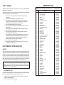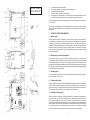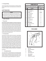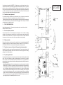
1
OPERATING & MAINTENANCE
INSTRUCTIONS
MIG 190T TURBO
MIG 220T TURBO
MIG 260T TURBO
7/97
SPARE PARTS LIST
Model: MIG 260T Turbo (SEE DIAGRAM ON PAGE 22)
Item
1
2
3
4
5
6
7
8
9
10
11
12
13
14
15
16
17
18
19
20
21
22
23
23
23
23
24
25
26
27
28
29
29A
30
31
32
33
34
35
36
37
38
39
40
41
42
43
44
45
Description
Part No. 6010390
Part No.
2 oval shaped handles
Printed circuit board
Gas solenoid valve
Rectifier
Rectifier thermostat
Complete fan
2 Cable clamps for hole D.20
2 Gas hoses
Input cable
Side panel locking clip
Left side panel
Torch grommet on front panel
Handle bar
Green pilot light switch
Timer switch
Right side panel
Orange pilot light
Power setting control switch knob
Power setting control switch
Top panel
Complete wire feeder
Wire feeding motor
Wire feed roller 0.6-0.8 mm
Wire feed roller 1.0-1.2 mm
Wire feed roller 0.8-1.0 mm (nylon)
Wire feed roller 1.2-1.6 mm (nylon)
Contactor
Dinsel socket
Voltage change board
Bottom panel
Transformer
2 Lateral windings
Central winding
Binzel torch connection
2 Castors
Wheel axle
2 Wheels
Back panel
Spool holde for coil D.50
Dividing panel
Front panel
Dinsel plug
Earth cable
Earth clamp
Torch with hose assembly
Reducer
Mask
Transparent glass
Dark glass
23
EM21600012
EM22710010
EM22900001
EM22400029
EM22210601
EM22800006
EM21605010
EM10900003
EM20220030
EM21690046
EM33705164
EM21690003
EM33725047
EM22200005
EM21690058
EM33705163
EM22610013
EM21690015
EM22205030
EM33705162
EM44410010
EM22810006
EM33805003
EM33805005
EM33805021
EM33805022
EM22225008
EM22100002
EM21890001
EM33700111
EM44125068
EM44025084
EM44025085
EM23005048
EM21625002
EM55200001
EM21625009
EM33714054
EM21690032
EM33720013
EM33710134
EM22100001
EM43210013
EM22110009
EM23000319
EM22905018
EM21905019
EM21905020
EM21905024
MIG 260T TURBO
Part No. 6010390
Thank you for purchasing this CLARKE Mig Welder. Before attempting to operate the machine,
please read this instruction manual and follow all directions carefully. This is for your own safety,
and that of others around you, and so that it will provide you with long and troublefree service.
GUARANTEE
This CLARKE product is guaranteed against faults in manufacture for 12 months from the
purchase date. Please keep your receipt which will be required as proof of purchase. This
guarantee is invalid if the product has been found to have been abused or tampered with in any
way, or not used for the purpose for which it was intended. The reason for return must be clearly
stated. This guarantee does not effect your statutory rights.
CONTENTS
Guarantee ...................................................................................... 3
Safety - Genera .............................................................................. 4
EMC Regulations. ........................................................................ 4-6
Safety Precautions ....................................................................... 6-9
Preparation of the Working Area ................................................... 9
Electrical Connections ................................................................... 9
Safety Equipment .......................................................................... 10
Welder Specification ..................................................................... 10
Assembly ....................................................................................... 10
Attaching Gas Bottle and Regulator ............................................. 11
Loading Wire ................................................................................. 12
Preparation for Welding ................................................................. 13
Operation ....................................................................................... 13
Tuning the Welder ......................................................................... 14
Welding Hints and Maintenance ................................................... 14
Troubleshooting ............................................................................. 15
Types of Joints .............................................................................. 16
Mig 190T Parts Diagram ............................................................... 17
Mig 190T Parts List .................................................................... 18-19
Torch Assembly Diagram and Parts List ...................................... 19
Mig 220T Parts Diagram ............................................................... 20
Mig 220T Parts List ....................................................................... 21
Mig 260T Parts Diagram ............................................................... 22
Mig 260T Parts List ....................................................................... 23
3
22
SAFETY - GENERAL
SPARE PARTS LIST
Special care is taken during all stages of manufacture to ensure that your CLARKE Mig Welder
arrives with you in good condition.
Before using the machine it is in your own interest to read this manual thoroughly, paying particular
attention to the following rules, and the EMC regulations:
1.
2.
3.
4.
5.
6.
7.
8.
9.
Do not open or remove side panels from the machine unless the mains plug is
disconnected.
Do not use the machine with any of the panels open or removed.
Do not attempt any electrical or mechanical repair unless you are a qualified
technician. If you have a problem with your machine contact your local dealer or
CLARKE International Service Department on 0181 556 4443.
Remove any flammable materials from the welding area.
Do not expose gas cylinder to high temperature, and do not strike an arc near or on
the gas cylinder.
CAUTION: Gas cylinders are pressurised containers. Do not pierce or burn, even
when empty. Protect from direct sunlight.
Make sure you have good ventilation in the welding area since toxic gases are
released during the MIG welding process.
Ultra-violet radiation is released by the MIG welding process and it is of the utmost
importance that the operator, and any spectators, protect themselves by using
welding face shields or helmets with suitable filter lenses. The wearing of gloves
and proper working clothes is also strongly recommended.
Never use in a wet or damp environment.
If welding outdoors, screens MUST be used around the weld site, to protect the
general public from the glare of the arc.
ELECTROMAGNETIC INTERFERENCE (EMC)
IMPORTANT
Whilst this unit complies with EMC regulations, the user is responsible for installing and using the
welding equipment according to the manufacturer’s instructions. If electromagnetic disturbances are
detected then it shall be the responsibility of the user of the welding equipment to resolve the
situation. In some cases this remedial action may be as simple as earthing the welding circuit, see
‘Note’ below. In other cases it could involve constructing an electromagnetic screen enclosing the
power source and the work complete with associated input filters. In all cases electromagnetic
disturbances must be reduced to the point where they are no longer troublesome.
Note - The welding circuit may or may not be earthed for safety reasons. Changing the earthing
arrangements should only be authorised by a person who is competent to assess whether the
changes will increase the risk of injury, e.g. by allowing parallel welding current return paths which
may damage the earth circuits of other equipment.
1.
ASSESSMENT OF AREA
Before installing welding equipment the user shall make an assessment of potential electromagnetic
problems in the surrounding area. Avoid using your welder in the vicinity of:
a)
b)
Model: MIG 220T Turbo (SEE DIAGRAM ON PAGE 20)
Item
1
2
3
4
5
6
7
8
9
10
11
12
13
14
15
16
17
18
19
20
21
22
23
24
25
26
27
28
29
30
31
32
33
34
35
36
37
38
39
40
41
42
43
44
45
46
47
48
Description
Part No.
2 oval shaped handles
Printed circuit board
Gas solenoid valve
Rectifier
Rectifier thermostat
Complete fan
2 Cable clamps for hole D.20
3 Gas hoses
Input cable
Side panel locking clip
Left side panel
Torch grommet on front panel
Handle bar
Orange pilot light
On/off switch
Right side panel
2 timer switches
Power setting control switch knob
Power setting control switch
Top panel
Complete wire feeder
Wire feeding motor
Wire feed roller
Contactor
Auxiliary contact
Dinsel socket
Choke
Resistance
Thermostat
Transformer
Capacitor
Binzel torch connection
2 Castors
Wheel axle
2 Wheels
Back panel
Spool holder for coil D.50
Bottom panel
Dividing panel
Front panel
Dinsel plug
Pressure regulator
Mask
Transparent glass
Dark glass
Earth clamp
Torch with hose assembly
Earth cable
other supply cables, control cables, signalling and telephone cables; above, below and
adjacent to the welding equipment;
radio and television transmitters and receivers;
4
Part No. 6010370
21
EM21600012
EM22710010
EM22900001
EM22400009
EM22210601
EM22800013
EM21605010
EM10900003
EM20220020
EM21690046
EM33705065
EM21690003
EM33725046
EM22610013
EM22200002
EM33705066
EM21690058
EM21690015
EM22205016
EM33705064
EM44400003
EM22810003
EM33805023
EM22225006
EM22225018
EM22100002
EM44135006
EM22305004
EM22210016
EM44120016
EM22315002
EM23005047
EM21625002
EM55200016
EM21625009
EM33715026
EM21690032
EM33700056
EM33720014
EM33710054
EM22100001
EM22905004
EM21905019
EM21905020
EM21905021
EM22110007
EM23000322
EM43210009
MIG 220T TURBO
Part No. 6010370
c)
d)
e)
f)
g)
computer and other control equipment;
safety critical equipment, e.g. guarding of industrial equipment;
pacemakers and hearing aids etc;
equipment used for calibration or measurement;
other equipment in the environment. The user shall ensure that other equipment being used
in the environment is compatible. This may require additional protection measures;
It may be possible to avoid the above by changing the time of day that welding or other activities are
to be carried out.
The size of the surrounding area to be considered will depend on the structure of the building and
other activities that are taking place. The surrounding area may extend beyond the boundaries of
the premises.
2.
METHODS OF REDUCING EMISSIONS
2.1
Mains supply
Welding equipment should be connected to the mains supply according to the manufacturer’s
recommendations. If interference occurs, it may be necessary to take additional precautions such
as filtering of the mains supply. Consideration should be given to shielding the supply cable of
permanently installed welding equipment, in metallic conduit or equivalent. Shielding should be
electrically continuous throughout its length. The shielding should be connected to the welding
power source so that good electrical contact is maintained between the conduit and the welding
power source enclosure.
2.2
Maintenance of the welding equipment
The welding equipment should be routinely maintained according to the manufacturer’s
recommendations. All access and service doors and covers should be closed and properly fastened
when the welding equipment is in operation. The welding equipment should not be modified in any
way except for those changes and adjustments covered in the manufacturer’s instructions. In particular,
the spark gaps of arc striking and stabilising devices should be adjusted and maintained according
to the manufacturer’s recommendations.
2.3
Welding cables
The welding cables should be kept as short as possible and should be positioned close together,
running at or close to the floor level.
2.4
Equipotential bonding
Bonding of all metallic components in the welding installation and adjacent to it should be considered.
However, metallic components bonded to the workpiece will increase the risk that the operator
could receive a shock by touching these metallic components and the electrodes at the same time.
The operator should be insulated from all such bonded metallic components.
2.5
Earthing of the workpiece
Where the workpiece is not bonded to earth for electrical safety, nor connected to earth because of
its size and position, e.g. ships hull or building steelwork, a connection bonding the workpiece to
earth may reduce emissions in some, but not all instances. Care should be taken to prevent the
earthing of the workpiece increasing the risk of injury to users, or damage to other electrical equipment.
Where necessary, the connection of the workpiece to earth should be made by a direct connection
to the workpiece, but in some countries where direct connection is not permitted, the bonding
should be achieved by suitable capacitance, selected according to national regulations.
5
20
2.6
Screening and shielding
SPARE PARTS LIST
Selective screening and shielding of other cables and equipment in the surrounding area may alleviate
problems of interference. Screening of the entire welding installation may be considered for special
applications.
SAFETY PRECAUTIONS
WARNING:
As with all machinery, there are certain hazards involved with their operation and use.
Exercising respect and caution will considerably lessen the risk of personal injury. However, if
normal safety precautions are overlooked, or ignored, personal injury to the operator may result.
FAILURE TO FOLLOW THESE RULES MAY RESULT IN SERIOUS PERSONAL INJURY
1.
GENERAL PRECAUTIONS
1.1
Burn prevention
Wear protective clothing - gauntlet gloves designed for use in welding, hat, and protective shoes.
Button shirt collar and pocket flaps, and wear cuffless trousers to avoid entry of sparks and slag.
Wear helmet with safety goggles or glasses with side shields underneath, appropriate filter lenses
or plates (protected by clear cover glass). This is a MUST for welding or cutting, (and chipping) to
protect the eyes from radiant energy and flying metal. Replace cover glass when broken, pitted, or
spattered. Avoid oily greasy clothing. A spark may ignite them. Hot metal such as electrode stubs
and workpieces should never be handled without gloves. First aid facilities and a qualified first aid
person should be available for each shift unless medical facilities are close by for immediate treatment
of flash burns of the eyes and skin burns. Ear plugs should be worn when working overhead or in a
confined space. A hard hat should be worn when others work overhead. Flammable hair preparations
should not be used by persons intending to weld or cut.
1.2
Item
50
51
52
53
54
55
56
57
58
59
60
61
62
63
64
65
66
67
Description
Pressure roller bracket
Pressure roller adjuster knob
Wire pressure roller
Wire liner
Wire liner support bracket
Support bracket cover
Flat copper washer
Electrical connector
Hose assembly support bracket
Brass collar
Wire liner plastic shroud
Hose assembly end nut
Brass nut
Electrical connection
Electrical connection
Hose support bracket assembly
Worm drive clip
Gas hose nipple
n/a
n/a
n/a
EM23005025
n/a
n/a
n/a
n/a
n/a
n/a
n/a
n/a
n/a
n/a
n/a
n/a
n/a
n/a
TORCH ASSEMBLY
Fire and explosion prevention
Causes of fire and explosion are: combustibles reached by the arc, flame, flying sparks, hot slag or
heated material; misuse of compressed gases and cylinders; and short circuits. BE AWARE THAT
flying sparks or falling slag can pass through cracks, along pipes, through windows or doors, and
through wall or floor openings, out of sight of the goggled operator. Sparks and slag can fly 10m. To
prevent fires and explosion: keep equipment clean and operable, free of oil, grease, and (in
6
A.
B.
C.
D.
E.
F.
G.
H.
Part No. 6010350
Part No.
Toxic fume prevention
Severe discomfort, illness or death can result from fumes, vapours, heat, or oxygen enrichment or
depletion that welding (or cutting) may produce. Prevent them with adequate ventilation. NEVER
ventilate with oxygen. Lead-, cadmium-, zinc-, mercury- and beryllium- bearing materials, when
welded (or cut) may produce harmful concentrations of toxic fumes. Adequate local exhaust ventilation
must be used, or each person in the area as well as the operator must wear an air- supplied respirator.
For beryllium, both must be used. Metals coated with or containing materials that emit toxic fumes
should not be heated unless coating is removed from the work surface, the area is well ventilated, or
the operator wears an air-supplied respirator. Work in a confined space only while it is being ventilated
and, if necessary, while wearing an air-supplied respirator. Vapours from chlorinated solvents can
be decomposed by the heat of the arc (or flame) to form PHOSGENE, a highly toxic gas, and other
lung and eye irritating products. The ultraviolet (radiant) energy of the arc can also decompose
trichloroethylene and perchloroethylene vapours to form phosgene. DO NOT WELD or cut where
solvent vapours can be drawn into the welding or cutting atmosphere or where the radiant energy
can penetrate to atmospheres containing even minute amounts of trichloroethylene or
perchloroethylene.
1.3
Model: MIG 190T Turbo (SEE DIAGRAM ON PAGE 17)
Torch handle
Torch neck with gas diffuser
Contact tip
Torch gas nozzle
Torch neck insulator collar
Torch neck insulator
Trigger assembly
Complete torch/hose assembly
19
SPARE PARTS LIST
Model: MIG 190T Turbo (SEE DIAGRAM ON PAGE 17)
Item
1
2
3
4
5
6
7
8
9
10
11
12
13
14
15
16
17
18
19
20
21
22
23
24
25
26
27
28
29
30
31
32
33
34
35
36
37
38
39
40
41
42
43
44
45
46
47
48
49
Description
Part No. 6010350
Part No.
2 oval shaped handles
Printed circuit board
Gas solenoid valve
Rectifier
Rectifier thermostat
Complete fan
2 Cable clamps for hole D.20
3 Gas hoses
Input cable
Side panel locking clip
Left side panel
Torch grommet on front panel
Handle bar
Orange pilot light
On/off switch
Right side panel
2 timer switches
Power setting control switch knob
Power setting control switch
Top panel
Complete wire feeder
Wire feeding motor
Wire feed roller
Contactor
Dinsel socket
Earth cable
Choke/Inductance
Spool holder hub
Transformer thermostat
Transformer
Earth clamp
Torch with hose assembly
2 Castors
Wheel axle
2 Wheels
Back panel
Spool holder for coil D.50
Bottom panel
Dividing panel
Front panel
Dinsel plug
Pressure regulator
Mask
Transparent glass
Dark glass
Spool holder outer collar
Spool holder spring
Spool holder knob
Wire guide
EM21600012
EM22710010
EM22900001
EM22400009
EM22210601
EM22800013
EM21605010
EM10900003
EM20220020
EM21690046
EM33705065
EM21690002
EM33725046
EM22610013
EM22200002
EM33705066
EM21690058
EM21690015
EM22205016
EM33705064
EM44400003
EM22810003
EM33805023
EM22225006
EM22100002
EM43210009
EM44135006
EM21690011
EM22210016
EM44120040
EM22110007
EM23000324
EM21625002
EM55200016
EM21625009
EM33715026
EM21690032
EM33700056
EM33720014
EM33710054
EM22100001
EM22905004
EM21905019
EM21905020
EM21905021
EM21690012
EM33800004
EM22180036
n/a
electrical parts) of metallic particles that can cause short circuits. If combustibles are in the area, do
NOT weld or cut. Move the work if practicable, to an area free of combustibles. Avoid paint spray
rooms, dip tanks, storage areas, ventilators. If the work cannot be moved, move combustibles at
least 10m away out of reach of sparks and heat; or protect against ignition with suitable and snug
fitting, fire-resistant covers or shields. Walls touching combustibles on opposite sides should not be
welded on (or cut). Walls, ceilings, and floor near work should be protected by heat resistant covers
or shields. Fire watcher must be standing by with suitable fire extinguishing equipment during and
for some time after welding or cutting if:
a)
appreciable combustibles (including building construction) are within 10m.
b)
appreciable combustibles are further than 10m but can be ignited by sparks.
c)
openings (concealed or visible) in floors or walls within 10m can expose
combustibles to sparks.
d)
combustibles adjacent to walls, ceilings, roofs or metal partitions can be ignited by
radiant or conducted heat.
After work is done, check that area is free of sparks, glowing embers, and flames. An empty container
that held combustibles, or that can produce flammable or toxic vapours when heated, must never be
welded on or cut, unless container has first been cleaned. This includes: a thorough steam or
caustic cleaning (or a solvent or water washing, depending on the combustible’s solubility) followed
by purging and inerting with nitrogen or carbon dioxide, and using protective equipment. Water filling
just below working level may substitute for inerting. A container with unknown contents should be
cleaned (see above), do NOT depend on sense of smell or sight to determine if it is safe to weld or
cut. Hollow castings or containers must be vented before welding or cutting - they can explode. In
explosive atmospheres, never weld or cut where the air may contain flammable dust, gas, or liquid
vapours.
2.
ELECTRIC ARC (MIG, TIG) WELDING
Comply with precautions in 1 above, and this section. Arc welding, properly done, is a safe process,
but a careless operator invites trouble. The equipment carries high currents at significant voltages.
The arc is very bright and hot. Sparks fly, fumes rise, ultraviolet and infrared energy radiates,
weldments are hot. The wise operator avoids unnecessary risks and protects himself and others
from accidents.
2.1
Burn protection
Comply with precautions in 1.1. The welding arc is intense and visibly bright. Its radiation can damage
eyes, penetrate lightweight clothing, reflect from light coloured surfaces and burn the skin and eyes.
Skin burns resemble acute sunburn, those from gas-shielded arcs are more severe and painful.
DON’T GET BURNED! COMPLY WITH PRECAUTIONS!
2.2
Protective clothing
Wear long sleeved clothing (particularly for gas shielded arc) in addition to gloves, hat and shoes
(see 1.1). As necessary, use additional protective clothing such as leather jacket or sleeves, flameproof
apron, and fire-resistant leggings. Avoid outer garments of untreated cotton. Protect bare skin. Wear
dark substantial clothing. Button collar to protect chest and neck and button pockets to prevent
entry of sparks.
2.3
Eye and head protection
Protect eyes from exposure to arc. NEVER look at an electric arc without protection. Welding
helmet or shield containing a filter plate shade no. 12 or denser must be used when welding. Place
over face before striking arc. Protect filter plate with a clear cover plate. Cracked or broken helmet or
shield should NOT be worn; radiation can pass through to cause burns.
Cracked, broken,
or loose
7
18
filter plates must be replaced IMMEDIATELY. Replace clear cover plate when broken, pitted, or
spattered. WE SUGGEST to wear flash goggles with side shields under the helmet, to give some
protection to the eyes should the helmet not be lowered over the face before an arc is struck.
Looking at an arc momentarily with unprotected eyes (particularly a high intensity gas-shielded arc)
can cause a retinal burn that may leave a permanent dark area in the field of vision. Seek advice
from your optician before welding whilst wearing contact lenses.
2.4
MIG 190T TURBO
Part No. 6010350
Protection of nearby personnel
For production welding, a separate room or enclosed bay is best. In open areas, surround the
operation with low reflective, non-combustible screens or panels. Allow for free air
circulation, particularly at floor level. Provide face shields for all persons who will be looking directly
at the weld. Others working in the area should wear flash goggles. Before starting to weld, make
sure that screen or bay doors are closed.
3.
TOXIC FUME PREVENTION
Comply with precautions in 1.2. Generator engine exhaust must be vented to the outside air.
CARBON MONOXIDE CAN KILL.
3.1
Fire and explosion prevention
Comply with precautions in 1.3 and equipment’s rated capacity. Do not overload arc welding
equipment. It may overheat cables and cause a fire. Loose cable connections may overheat or flash
and cause a fire. Never strike an arc on a cylinder or other pressure vessel. It creates a brittle area
that can cause a violent rupture or lead to such a rupture later under rough handling.
3.2
Shock prevention
Exposed hot conductors or other bare metal in the welding circuit, or in unearthed, electrically-HOT
equipment can fatally shock a person whose body becomes a conductor. DO NOT STAND, SIT,
LIE, LEAN ON, OR TOUCH a wet surface when welding, without suitable protection.
3.3
Protection for wearers of electronic life support devices (pacemakers)
Magnetic fields from high currents can effect pacemaker operation. Persons wearing electronic life
support equipment (pacemaker) should consult with their doctor before going near arc welding,
gouging, or spot welding operations.
3.4
To protect against shock:
Keep body and clothing dry. Never work in a damp area without adequate insulation against electrical
shock. Stay on a dry duckboard, or rubber mat when dampness or sweat can not be avoided.
Sweat, sea water, or moisture between body and an electrically HOT part - or grounded metal reduces the body surface electrical resistance, enabling dangerous and possibly lethal currents to
flow through the body.
a) Grounding the equipment - When arc welding equipment is grounded according to the National
Electrical Code, and the work is grounded, a voltage may exist between the electrode and any
conducting object. Examples of conducting objects include, but are not limited to, buildings, electrical
tools, work benches, welding power source cases, workpieces, etc. Never touch the electrode
and any metal object unless the welding power source is off. When installing, connect the frames
of each unit such as welding power source, control, work table, and water circulator to the building
ground. Conductors must be adequate to carry ground currents safely. Equipment made electrically
HOT by stray current may shock, possibly fatally. DO NOT GROUND to electrical conduit, or to a
pipe carrying ANY gas or a flammable liquid such as oil or fuel.
8
17
b) Electrode holders - Fully insulated electrode holders should be used. Do NOT use holders with
protruding screws or with any form of damage.
c) Connectors - Fully insulated lock-type connectors should be used to join welding cable lengths.
d) Cables - Frequently inspect cables for wear, cracks and damage. IMMEDIATELY REPLACE
those with excessively worn or damaged insulation to avoid possibly lethal shock from bared
cable. Cables with damaged areas may be taped to give resistance equivalent to original cable.
Keep cable dry, free of oil and grease, and protected from hot metal and sparks.
e) Terminals and other exposed parts - Terminals and other exposed parts of electrical units
should have insulating covers secured before operation.
f) Electrode - i) Equipment with output on/off control (contactor)
Welding power sources for use with the gas metal arc welding, gas tungsten arc welding and
similar processes normally are equipped with devices that permit on/off control of the welding
power output. When so equipped the electrode wire becomes electrically HOT when the power
source switch is ON and welding gun switch is closed. Never touch the electrode wire or any
conducting object in contact with the electrode circuit unless the welding power source is off.
- ii) Equipment without output on/off control (no contactor)
Welding power sources used with shielded metal arc welding and similar processes may not be
equipped with welding power output on/off control devices. With such equipment the electrode is
electrically HOT when the power switch is turned ON. Never touch the electrode unless the welding
power source is off.
g) Safety devices - Safety devices such as interlocks and circuit breakers should not be
disconnected or shunted out. Before installation, inspection, or service of equipment, shut OFF all
power and remove line fuses (or lock or red-tag switches) to prevent accidental turning ON of
power. Do not open power circuit or change polarity while welding. If, in an emergency, it must be
disconnected, guard against shock burns, or flash from switch arcing. Always shut OFF and
disconnect all power to equipment. Power disconnect switch must be available near the welding
power source.
PREPARATION OF THE WORKING AREA
The working area must be sufficiently spacious, not humid, and well-ventilated as to avoid any
fumes which develop from the welding process and from incidental material adhering to the pieces
to be welded (oils, paints, tars...) which may cause annoyance to the operator.
Avoid welding by contact with humid parts or near to combustible liquids. Least of all, do not weld
upon tanks which may contain inflammable residuals.
ELECTRICAL CONNECTIONS
WARNING: This machine MUST be earthed. This welder must be connected to a 230 V (50 Hz)
supply, having a rated capacity of greater than 12 amps. A 13 amp (BS1363) plug is NOT supplied
for this device. Connect the three core mains leads to a suitably fused supply through an isolator or
heavy duty plug.
IMPORTANT: The wires in the mains lead are coloured in accordance with the following code:
Green and yellow
Earth
Blue
Neutral
Brown
Live
Connect GREEN & YELLOW cord to plug terminal marked with a letter “E” or the earth symbol.
Connect BROWN cord to plug terminal marked with a letter “L”.
Connect BLUE cord to plug terminal marked with a letter “N”.
We recommend that this machine is connected to the mains supply through a Residual Current
Device (RCD). If in doubt, consult a qualified electrician. Do not attempt any electrical repairs yourself.
Fuse rating is indicated on the machine’s specification plate.
16
9
SAFETY EQUIPMENT
TROUBLESHOOTING
A comprehensive range of CLARKE safety equipment for use when welding is available from your
local CLARKE dealer.
WELDER SPECIFICATIONS
Your CLARKE Mig Welder has been designed to give long and trouble free service. If, however,
having followed the instructions in this booklet carefully, you still encounter problems, the
following points should help identify and resolve them. If you have any problems which cannot be
resolved here, please contact your local Clarke dealer.
PROBLEM
The technical specifications for your unit are printed on the data plate on the front of the machine.
The data plate carries the following information:
1.
Supply Voltage
2.
Duty Cycle - percentage of a period of 10 minutes in which the unit can operate at a stated
current output with no risk of over-heating or internal damage. e.g. a unit with a duty cycle of
60% at 80 Amps can weld for 6 minutes over a 10 minute period at 80 Amps. Down time is 4
minutes over a 10 minute period.
3.
Primary or input power data, number of phases and supply frequency
4.
Fuse Rating
5.
Protection
6.
Insulation class
7.
Type of static characteristic
8.
Welder type and batch number
9.
Regulation range
CAUSE
Check fuses and mains lead
a) Replace fuses as necessary. If
problem persists, return welder
to your local dealer.
b) Check fuse size.
2. No wire feed.
Motor malfunction
Return welder to your local dealer.
3. Feed motor operates but
wire will not feed.
a) Insufficient feed roller pressure
b) Burr on end of wire
c) Liner blocked or damaged
a) Increase roller presure
b) Re-cut wire square
c) Clear with compressed air or
replace liner
d) Use only good clean wire
d) Inferior wire
4. Wire welds itself to tip
a) Wire feed speed too low
b) Wrong size tip
ASSEMBLY
1.
2.
5. Wire feeds into ‘bird’s
nest’ tangle
Refer to the appropriate parts diagram for your machine (190T page 17, 220T page 20, 260T
page 22).
Remove the side panel by sliding it upwards and check that all the accessories listed below
are included:
2 wheels
1 gas regulator
1 axle
1 0.6mm welding tip
2 wheel retaining washers
1 0.8mm welding tip
2 castors
1 1.0mm welding tip
1 handle with brackets
1 chain
4 screws
1 mask handle
1 mask body
1 welding torch and lead (fitted)
1 earth lead and clamp
a) Wire welded to tip
b) Wire liner damaged preventing
smooth operation
4.
5.
6.
7.
Attach the handle to the welder unit by sliding the brackets into the holes provided on the front
of the machine, lining up the holes with those in the casing and securing the four screws
provided.
Fix the wheels to the back of the unit and the castors to the front.
Connect the earth return lead to the negative ( - ) socket on the front panel of the welder unit.
Ensure that the side panels are securely closed before using the welder.
Connect the torch lead assembly to the welder, following the appropriate instructions below:
TORCH LEAD ASSEMBLY INSTRUCTIONS
a) Unscrew tip, cut wire and fit
new tip. Increase wire speed
before operating again.
b) Renew wire liner
a) As above plus reduce feed roller
presure so that if blockage occurs
wire slips on roller, i.e. no feed
b) Renew wire liner
6. Loose coils of wire tangle
around wire drum inside
machine
Drum brake too slack
Tighten drum brake - DO NOT
OVERTIGHTEN
7. Erratic wire feed
a) Drum brake too tight
b) Feed roller worn
c) Insufficient pressure on
feed roller
d) Wire dirty, rusty, damp or bent
e) Liner partially blocked
a) Loosen drum brake slightly
b) Check and replace if necessary
c) Increase pressure on feed roller
DO NOT OVERTIGHTEN
d) Re-cut wire & ensure it is clean
e) Clear with compressed air
8. Poor quality welds
a) Insufficient gas at weld area
a) Check that gas is not being
blown away by draughts, if so,
move to a sheltered area. If no
draught, increase gas supply
b) Consult your Mig welding manual
c) Ensure workpiece is clean & dry
d) Ensure wire is clean and dry
e) Check ground clamp/workpiece
connection
SHOULD ANY PART BE MISSING OR DAMAGED, CONTACT YOUR
LOCAL DEALER FOR REPLACEMENT
3.
REMEDY
1. No ‘life’ from welder
b) Incorrect gas/wire combination
c) Rusty, painted, damp, oily or
greasy workpiece
d) Rusty/diry wire
e) Poor earth contact
9. Wire jams in tip when
welding aluminium
Tip too small
Use slightly oversize tip i.e. for 0.8
mm wire use 1 mm tip (Applies to
aluminium only)
10. Welder cuts out whilst in
use
Duty cycle exceeded (auto cut-out
operates)
Allow welder to cool for 15-30 mins
before continuing. Note: if duty cycle
is continually exceeded, damage to
the welder may result and welder
output is probably too small for
application.
MIG 220T and MIG 260T
Plug the torch hose into the socket on the front of the welder and secure by hand screwing in
the threaded connection.
10
15
TUNING THE WELDER
The tuning of a Mig welding machine requires some practice, due to the fact that, (contrary to the arc
welding procedure) two parameters must be accommodated to achieve the perfect weld. These are:
Wire feed speed and
Welding current.
It is important to arrive at the correct combination to suit the type and thickness of material to be
welded. The wire speed is directly dependent upon the current.
If the current is increased, the wire feed speed is also increased, whereas the arc length is shortened.
Conversely, if the current is decreased, the wire feed speed is therefore decreased, and the length
of arc is increased.
An increase in the welding voltage leads to a longer arc, (without substantially effecting the current).
A decreased welding voltage results in a shorter arc, (the current again is not substantially changed).
A change in wire diameter results in changed parameters. A smaller diameter wire requires an
increase in current to reach the same wire feed speed.
If certain limits are exceeded, a satisfactory weld cannot be obtained. These are:
A) If the wire feed speed is too high, (in relation to the welding voltage) pulsing will occur
within the torch. This is because the wire electrode dips into the puddle and cannot be melted
off fast enough.
B) If the welding voltage is set too high large drops can be seen at the end of the wire
electrode. These drops are often deposited beside the welding seam.
The correct rate of current, (wire feed speed) and welding voltage results in less spatter and a
continuous, intensive hissing can be heard from the arc.
WELDING HINTS AND MAINTENANCE
1.
2.
3.
4.
5.
6.
7.
8.
9.
10.
11.
Always weld clean, dry and well prepared material.
Hold gun at 45° angle to the workpiece with nozzle about 6 mm from the surface.
Move the gun smoothly and steadily as you weld.
Avoid welding in draughty areas. A weak, pitted and porous weld will result, due to air blowing
away the protective welding gas.
Keep wire and wire liner clean. Do not use rusted wire.
Sharp bends or kinks on the welding hose should be avoided.
Always try to avoid getting particles of metal inside the machine as these can cause short
circuits.
If available, use compressed air to periodically clean the hose liner when changing wire
spools. IMPORTANT: Disconnect from power source when carrying out this operation.
Using low pressure air, (20-30 PSI) occasionally blow the dust from the inside of the welder.
This keeps the machine running cooler. NOTE: Do not blow air over the printed circuit
board and electronic components.
The wire feed roller will eventually wear during normal use. With the correct tension the
pressure roller must feed the wire without slipping. If the pressure roller and the wire feed
roller make contact, (when the wire is in place between them) the wire feed roller MUST be
replaced.
Check all cables periodically. They must be in good condition and not cracked.
MIG 190T (Ref to Fig 1)
Fig 1
(a) It is necessary to fit the
torch hose assembly (32) on
to the machine, but before
doing so you must first
measure the length of
protusion of the liner (53) from
the brass nut (61).
IMPORTANT:
This
measurement should be a
maximum of 18 mm (see
Fig 1), and if necessary
should
be
carefully
trimmed to this length
using a good pair of side
cutters, or similar, ensuring
there are no burrs or sharp edges which may impede the progress of the wire when fitted.
(b) Having checked the protusion of the liner, and trimmed where necessary, remove the washer
(56) and nut (62) from the end of the torch assembly (32). Carefully feed the hose assembly through
the hole in the front face of the welder (40), taking care to feed the electrical connectors (64) through
at the same time. Continue to feed the hose assembly through the brass collar (59) in the bracket
assembly (58).
(c) You will notice an electric terminal (57) roughly in position to be threaded on to the end of the
hose assembly, as it appears through the brass collar (59) in the bracket assembly (56). Thread the
terminal on to the hose assembly, followed by the washer (56) and screw on the nut (62). Carefully
tighten the nut.
NOTE: When correctly assembled, the wire liner (53) must not be in contact with the wire feed
roller (23).
(d) Fit the plastic cover (55) over the complete assembly, securing with the two self tapping screws
provided.
(e) Connect the gas hose (65) to the gas hose nipple (67) securing with the worm drive clip (66)
provided.
(f) Make the electrical connections by joining connectors 63 and 64.
NOTE: The connectors are a one-way fit, and simply clip together - do not use excessive
force.
FACE MASK
To assemble the face mask, first place the dark glass window (45) and the clear glass window (44)
together in the recessed window area of the body (43).
IMPORTANT: The clear glass window should be placed on the outside of the mask.
Secure in place using the screws and nuts provided. Bend the sides of the mask into shape and fix
together using the screws and nuts provided, and finally, fit the handle to the shield body also using
the screws and nuts provided.
ATTACHING GAS BOTTLE AND REGULATOR
1.
2.
3.
4.
14
The bottle (not supplied) should be located at the rear of the welder, securely held in position
by the chain provided.
For safety and economy, ensure that the regulator is fully closed, (turning anti-clockwise)
when not welding and when fitting or removing from the gas cylinder.
Connect the gas hose (8) to the regulator (42), securing with the clip/nut provided.
Screw the gas regulator (42) fully down on to the gas bottle valve, and fully tighten.
11
5.
Turn the power on, open the cylinder valve, then set the gas flow to approx. 8 l/min on the
regulator. Operate the torch trigger to ensure that the gas is flowing through the torch.
machine and press the trigger. The wire will feed through the hose and when it appears at the
torch end release the trigger, switch off the machine and replace the contact tip and the torch
shroud.
NOTE: If you experience difficulties in obtaining gas supplies,
contact your local CLARKE dealer.
IMPORTANT: ENSURE THE HOSE IS KEPT STRAIGHT DURING THIS OPERATION,
TO ASSIST THE WIRE AS IT IS FED THROUGH THE NOZZLE.
LOADING WIRE
PREPARATION FOR WELDING
NOTE: The MIG 190T Turbo, MIG 220T Turbo and MIG 260T Turbo are designed to accept either
5kg or 15kg wire spools of mild steel, stainless steel or aluminium according to the type of metal you
wish to weld. Wire spools ARE NOT supplied with the unit and must be purchased separately.
1.
2.
1.
2.
3.
4.
5.
6.
7.
8.
Ensure that the gas and electrical supplies
Fig 2
are disconnected.
(Ref Fig. 2) To fit your wire spool first
remove parts 46, 47 and 48, and then
simply slide it over the hub (28), ensuring
that the spool’s wire supports fit snugly on
the shoulder of the inner collar.
Replace the outer collar (46), (centralising
the wire spool about the hub) followed by
the spring (47) and plastic knob (48)).
Initially tighten the plastic knob (48)
sufficiently to allow the spool to rotate
smoothly but with a slight amount of
braking friction. Do not over-tighten as this
will exert undue pressure on the
wire drive motor and may cause
Fig 3
damage.
(Ref Fig. 1 on page 11)
Loosen the plastic knob (51) by
turning it anti-clockwise, (this
maintains pressure on the wire via
the roller (52)). Pull the plastic
knob so that the screw rod comes
out of its slot, thereby releasing
the pivoted roller bracket (50).
Raise the bracket together with
the pressure roller (52), and pull
out any wire that has been left in the hose.
If you are changing the size of the wire you must also select the appropriate groove on the
feed roller (23) (Ref Fig. 3). To change to the other groove undo the allen screw and remove
the roller from its shaft. Turn it through 180°, replace it on its shaft and adjust so that the
groove is directly in line with the wire liner (Ref Fig. 3). Firmly secure it in that position with
the allen screw.
Clip the end of the wire cleanly, ensuring there are no burrs or sharp edges, and ensuring it
is straight, feed it through the guide tube (74) over the channel on the roller (23) and into the
wire liner by approx. 10-15 cm.
Reposition the pressure roller (52) and plastic knob (51) and tighten slightly.
3.
4.
Attach the earth clamp to the bare metal to be welded, making sure of good contact.
Make sure that the wire-roller groove in the roller corresponds to the diameter of the welding
wire being used. Refer to ‘Loading Wire’ above.
Plug the machine into a 230 V AC (50 Hz) outlet.
Open the gas valve on the gas cylinder regulater, (turn knob clockwise) and adjust the gas
regulater to the proper setting position. NOTE: this varies with different metals,
thicknesses and currents. Refer to a MIG welding manual for instructions.
OPERATION
1.
2.
3.
4.
The MIG260T has 7 welding positions and the MIG190T and 220T have 6 welding positions
(see the table below) in which to regulate current for various conditions.
The selection of a welding position is determined by the thickness of the metal to be welded.
The thicker it is, the higher the current must be.
According to the thickness to be welded, the amount of gas regulated to the work also varies
and must be adjusted accordingly.
For welding adjustments, refer to the table below.
WARNING:
(i)
Make sure all flammable materials are removed from the work area.
(ii)
Never look at the welding arc - it can seriously damage your eyes. Always use an
approved welding mask or helmet.
(iii) Wear protective clothing so that all skin areas are covered.
(iv) Keep a fire extinguisher to hand.
SWITCH
1
2
7
1
2
3
4
5
6
7 (MIG260T Turbo only)
Pull off the torch shroud (D) (Ref Fig. 4, page 19) and unscrew the contact tip (C). Close the
side panel of the machine, plug into the mains, switch on the
12
0.6
0.6
0.6 - 0.8
0.6 - 0.8
0.8
0.8
1.0
Low
Low
Medium
Medium
Medium - High
High
High
4
5
TOO TIGHT WILL CRUSH THE WIRE AND DAMAGE THE WIRE FEED MOTOR,
TOO LOOSE WILL NOT ALLOW THE WIRE TO BE PULLED BY THE ROLLER.
9.
WIRE SPEED
ADJUSTMENT
3
6
Switch
positions
STEEL WIRE
DIAMETER (mm)
13