1
S8 Floor Stand
Instructions for use
G-30-1346-en
Issue 4.0
Printed on 05. 06. 2001
Contents
Functions at a glance
5
–
S8 Floor Stand
6
–
Key to symbols
8
Safety
G-30-1346-en
9
–
Directives and standards
10
–
Notes on installation and use
11
–
Safety devices
16
–
Warning labels and notes
24
Description
27
S8 floor stand
29
–
Intended use
29
–
Description of the modules
30
–
Design
30
–
Stand base with stand column
34
–
Connection panel
36
–
Suspension arm
38
–
Display field with control keys
40
–
Halogen illumination system
42
–
Xenon illumination system
46
Preparations for use
51
Attaching the equipment
52
Connections
56
–
Connecting the surgical microscope
56
–
Connecting the S light guide
56
–
Mounting the strain relief device
58
–
Connecting the stand
60
–
Positioning the stand
61
S8 Floor Stand
Issue 4.0
Printed on 05. 06. 2001
Operation
63
Preparations for use
64
–
Adjusting the balance setting of the suspension arm
64
–
Adjusting the limit of downward movement
66
–
Relocating the stand
68
–
Checklist
70
Using the display and key field
72
–
General functions
72
–
Operating the OPMI® Vario
76
–
Operating VISU 150 and VISU 200
96
–
Operating the OPMI® PRO magis
108
What to do in an emergency
114
–
Failure of a halogen lamp
114
–
Failure of the xenon lamp
116
–
Failure of lamp control
118
–
Failure of focusing system
118
–
Failure of magnetic clutches
118
Maintenance / Further information
121
–
Trouble-shooting table
122
–
Changing the halogen lamp
126
–
Changing the xenon lamp module
130
–
Care of the unit
132
–
Sterilization
132
–
Disinfecting the control keys
133
–
Ordering data
134
–
Accessories
134
–
Spare parts
135
–
Technical data
136
–
Ambient requirements
139
Index
G-30-1346-en
S8 Floor Stand
141
Issue 4.0
Printed on 05. 06. 2001
5
Functions at a glance
Functions at a glance
G-30-1346-en
S8 Floor Stand
6
Key to symbols
8
S8 Floor Stand
Issue 4.0
Printed on 05. 06. 2001
6
Functions at a glance
S8 Floor Stand
5
6
7
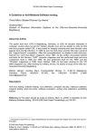
Halogen illumination system
Closed flap: main lamp is on - Open flap: backup lamp is on
Filter knob
Opening the lamp module
Manual selection of backup lamp
Xenon illumination system
Filter knob
Manual selection of backup lamp
Opening the lamp module
8
9
10
11
12
13
14
15
16
17
18
19
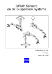
Switching on the stand
Connection panel
Rated voltage display
Connector for foot control panel or hand control panel
Locking the suspension arm in its horizontal position
Setting the limit of downward travel
Releasing the magnetic clutches of the stand
Balance setting
Lamp housing for halogen illumination (or xenon illumination)
Removing and mounting the coupling for the surgical microscope
Control panel
Brake for locking the stand in position
1
2
3
4
1
G-30-1346-en
2
3
4
S8 Floor Stand
5
6
7
Issue 4.0
Printed on 05. 06. 2001
7
Functions at a glance
14
15
16
18
17
13
12
11
10
9
8
19
G-30-1346-en
S8 Floor Stand
Issue 4.0
Printed on 05. 06. 2001
8
Functions at a glance
Key to symbols
Different symbols used in this user's manual draw your attention to safety
aspects and useful tips. The symbols are explained in the following.
Warning!
The warning triangle indicates potential sources of danger which may
constitute a risk of injury for the user or a health hazard.
Caution:
The square indicates situations which may lead to malfunction, defects,
collision or damage of the instrument.
Note:
The hand indicates hints on the use of the instrument or other tips for the
user.
OPMI®
G-30-1346-en
OPMI® is a registered trademark of Carl Zeiss.
S8 Floor Stand
Issue 4.0
Printed on 05. 06. 2001
9
Safety
Safety
G-30-1346-en
Directives and standards
10
Notes on installation and use
11
Safety devices
16
Warning labels and notes
24
S8 Floor Stand
Issue 4.0
Printed on 05. 06. 2001
10
Safety
The instrument described in this manual has been developed and tested
in accordance with Carl Zeiss safety standards and with national and international regulations. A high degree of instrument safety is thus ensured.
We would like to inform you on the safety aspects involved in operating
the instrument. This chapter contains a summary of the most important
precautions to be observed.
Further safety notes are also contained in other parts of this user's
manual; they are marked with a warning triangle containing an exclamation mark as shown here. Please pay special attention to these safety
notes.
Safety is only ensured when this instrument is operated properly. Please
read through this manual carefully before turning the instrument on. Also
read through the user's manuals of the other equipment used with this instrument. You may obtain further information from our service organization or authorized representatives.
Directives and standards
The instrument described in this manual has been designed in compliance with the following standards:
– EN
– IEC
– UL
– CSA
In accordance with Directive 93/42/EEC, Annex II, Article 3, the qualitymanagement system of Carl Zeiss has been approved by TÜV Rheinland,
which is a notified body. The registration number is: 95 102 7601.
G-30-1346-en
•
The instrument must be connected to a special emergency backup
line supply in accordance with the regulations or directives which apply in your country.
•
This is a class I instrument as defined by Directive 93/42 /EEC.
•
Please observe all applicable accident prevention regulations.
S8 Floor Stand
Issue 4.0
Printed on 05. 06. 2001
11
Safety
Notes on installation and use
Safe working order
•
G-30-1346-en
Do not operate the equipment contained in the delivery package in
–
explosion-risk areas,
–
the presence of inflammable anesthetics or volatile solvents such
as alcohol, benzine or similar chemicals.
•
Do not station or use the instrument in damp rooms. Do not expose
the instrument to water splashes, dripping water or sprayed water.
•
Immediately unplug any equipment that gives off smoke, sparks or
strange noises. Do not use the instrument until our service representative has repaired it.
•
Do not place any fluid-filled containers on top of the instrument. Make
sure that no fluids can seep into the instrument.
•
Do not force cable connections. If the male and female parts do not
readily connect, make sure that they are appropriate for one another.
If any of the connectors are damaged, have our service representative
repair them.
•
Do not use a mobile phone in the vicinity of the equipment because
the radio interference can cause the equipment to malfunction. The effects of radio interference on medical equipment depend on a number
of various factors and are therefore entirely unforeseeable.
•
Potential equalization: If desired, the unit can be incorporated in potential equalization measures. The potential equalization bolt is required for this purpose, see chapter "Description".
•
Modifications and repairs on these instruments or instruments used
with them may only be performed by our service representative or by
other authorized persons.
•
The manufacturer will not accept any liability for damage caused by
unauthorized persons tampering with the instrument; this will also forfeit any rights to claim under warranty.
•
Use this instrument only for the applications described.
•
Only use the instrument with the accessories supplied. Should you
wish to use other accessory equipment, make sure that Carl Zeiss or
the equipment manufacturer has certified that its use will not impair
the safety of instrument.
S8 Floor Stand
Issue 4.0
Printed on 05. 06. 2001
12
Safety
•
Only personnel who have undergone training and instruction are allowed to use this instrument. It is the responsibility of the customer or
institution operating the equipment to train and instruct all staff using
the equipment.
•
Keep the user's manuals where they are easily accessible at all times
for the persons operating the instrument.
•
Never look at the sun through the binocular tube, the objective lens or
an eyepiece.
•
Do not pull at the light guide cable, at the power cord or at other cable
connections.
•
This instrument is a high-grade technological product. To ensure optimum performance and safe working order of the instrument, its safety
must be checked once every 12 months. We recommend having this
check performed by our service representative as part of regular maintenance work.
If a failure occurs which you cannot correct using the trouble-shooting
table, attach a sign to the instrument stating it is out of order and contact our service representative.
Requirements for operation
Our service representative or a specialist authorized by us will install the
instrument. Please make sure that the following requirements for operation remain fulfilled in the future:
–
All mechanical connections (details in the user's manual) which are
relevant to safety are properly connected and screw connections tightened.
–
All cables and plugs are in good working condition.
–
The voltage setting on the instrument conforms to the rated voltage of
the line supply on site.
–
The instrument is plugged into a power outlet which has a properly
connected protective earth contact.
–
The power cord being used is the one designed for use with this instrument.
Before every use and after re-equipping the instrument
G-30-1346-en
•
Make sure that all ”Requirements for operation” are fulfilled.
•
Go through the checklist.
•
Re-attach or close any covers, panels or caps which have been removed or opened.
S8 Floor Stand
Issue 4.0
Printed on 05. 06. 2001
13
Safety
•
Pay special attention to warning symbols on the instrument (triangular
warning signs with exclamation marks), labels and any parts such as
screws or surfaces painted red.
•
Do not cover any ventilation openings.
For every use of the instrument
•
Always position the stand in such a way that the long extension of the
stand base points in the direction of the surgical field (if the instrument
is equipped with a base of this type).
•
The transport casters must be retracted to ensure that the unit is securely resting on its base (with instruments with retractable transport
casters).
•
Avoid looking directly into the light source, e.g. into the microscope objective lens or a light guide.
•
When the illumination is on, the light guide must be connected at both
ends. Otherwise there is a risk of fire or burn injuries.
•
Make sure that the instrument has been switched off before you
change the xenon lamp module. When switched on, the ignition system generates high voltage.
•
The xenon illumination system is a high-intensity light source which if used improperly - can cause thermal injury to skin or tissue. Keep
the exposed tissue moist and provide sufficient irrigation. Carefully
monitor the effects of the illumination on the tissue, in particular in the
following cases:
–
during prolonged procedures on skin and tissue using objective
lenses with a short focal length (short working distance),
–
during procedures on tissue with a low blood supply,
–
with high brightness settings of the xenon lamp.
•
Since the xenon lamp provides high light intensity and generates light
with a spectrum similar to daylight, it must not be used for ophthalmic
applications.
•
Any kind of radiation has a detrimental effect on biological tissue.This
also applies to the light illuminating the surgical field. Please therefore
reduce the brightness and duration of illumination on the surgical field
to the absolute minimum required.
After every use of the instrument
•
G-30-1346-en
Always use the main power switch of the instrument to turn it off.
S8 Floor Stand
Issue 4.0
Printed on 05. 06. 2001
14
Safety
•
G-30-1346-en
The main power switch must always be turned off when the instrument
is not in use.
S8 Floor Stand
Issue 4.0
Printed on 05. 06. 2001
15
Safety
G-30-1346-en
S8 Floor Stand
Issue 4.0
Printed on 05. 06. 2001
16
Safety
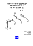
Safety devices
G-30-1346-en
1
Release bar
Allows non-sterile persons to release the magnetic clutches of the
ceiling mount (floor stand).
2
Adjustment screw for limiting the downward travel
Use this screw to set the minimum vertical distance (working distance)
from the surgical field. Check this setting before each surgical procedure.
3
Locking knob
for locking the suspension arm in its horizontal position.
Before removing or attaching a unit (microscope, tube, etc.), move the
suspension arm into a horizontal position. Pull out the locking knob
and turn it clockwise or counterclockwise through 180°, while slightly
moving the suspension arm up and down until the lock engages.
When locked, the suspension arm can no longer suddenly spring upward when insufficient weight is attached. After attaching a unit, perform the balancing procedure.
S8 Floor Stand
Issue 4.0
Printed on 05. 06. 2001
17
Safety
1
2
3
G-30-1346-en
S8 Floor Stand
1
Issue 4.0
Printed on 05. 06. 2001
18
Safety
Halogen illumination system
1
Activating the backup lamp
Each of the two lamp housings contains a backup lamp which will be
automatically activated if the first lamp fails. If this automatic function
fails, you can switch on the backup lamp by pressing this button.
2
GG 475 retina protection filter
When operating on the eye, always use a GG 475 protection filter to
ensure that the patient's retina is not exposed to unnecessary (blue)
radiation (risk of retinal injury). The filter knobs have four positions:
3
0
no filter
1
GG 475 filter: to protect the patient's eye during surgery against
unnecessary (blue) radiation (retinal injury).
2
KK 40 filter: to increase color temperature
3
no filter
Yellow indicator lamp
– Lights when the main lamp has failed. In addition, the open flap on
the lamp module indicates that the main lamp has failed. The backup lamp is on.
– Blinks when the backup lamp has failed.
4
G-30-1346-en
Manual function
When the manual function has been activated, all electrical control
systems are inoperative. The lamp brightness is automatically adjusted to a fixed setting.
S8 Floor Stand
Issue 4.0
Printed on 05. 06. 2001
19
Safety
1
2
3
4
G-30-1346-en
S8 Floor Stand
Issue 4.0
Printed on 05. 06. 2001
20
Safety
Xenon illumination system
G-30-1346-en
1
Activating the backup lamp
The lamp module contains two xenon lamps. The second lamp is used
as a backup lamp which has to be swung into the illumination beam
path when the first lamp fails.
If the xenon lamp fails, open the lamp module as follows:
Press button (4). The lamp module is slightly ejected. Pull out the lamp
module all the way. Turn knob (1) through 180° until it snaps in. This
moves the backup lamp into the illumination beam path. Push the
lamp module all the way back into the lamp housing.
2
Yellow indicator lamp
Lights when the lamp has failed. After activation and ignition of the
backup lamp, the yellow indicator lamp goes out again.
3
Manual function
When the manual function has been activated, all electrical control
systems are inoperative. The lamp brightness is automatically adjusted to a fixed setting.
S8 Floor Stand
Issue 4.0
Printed on 05. 06. 2001
21
Safety
1
4
2
3
G-30-1346-en
S8 Floor Stand
Issue 4.0
Printed on 05. 06. 2001
22
Safety
Manual function
1
Manual key
The Manual key permits you to switch to manual operation. The motorized control functions of the surgical microscope are deactivated.
The lamp brightness is automatically adjusted to a fixed setting, the
value being shown in the first display section.
When the manual mode is activated, the yellow LED is lit and the word
"MANUAL" blinks in the third display section.
The surgical microscope can no longer be operated via the foot control
panel, the handgrips or the display and key field.
In the manual mode, you can only switch the illumination on and off on
the foot control panel and release the magnetic clutches by pressing
the appropriate key on the surgical microscope.
The manual mode is retained even if you turn the power switch of the
instrument off and on again.
Press the Manual key once again to reactivate electronic control; the
display in the display and key field then returns to the basic mode.
G-30-1346-en
S8 Floor Stand
Issue 4.0
Printed on 05. 06. 2001
23
Safety
1
G-30-1346-en
S8 Floor Stand
Issue 4.0
Printed on 05. 06. 2001
24
Safety
Warning labels and notes
Caution:
Observe all warning labels and notes!
If any label is missing on your instrument or has become illegible, please
contact us or one of our authorized representatives. We will supply the
missing labels.
OPHTHALMOLOGY
G-30-1346-en
S8 Floor Stand
Issue 4.0
Printed on 05. 06. 2001
25
Safety
G-30-1346-en
S8 Floor Stand
Issue 4.0
Printed on 05. 06. 2001
26
Safety
G-30-1346-en
S8 Floor Stand
Issue 4.0
Printed on 05. 06. 2001
Description
27
S8 floor stand
29
Intended use
29
Description of the modules
30
Design
30
Stand base with stand column
34
Connection panel
36
Suspension arm
38
Display field with control keys
40
Halogen illumination system
42
Xenon illumination system
46
Description
G-30-1346-en
S8 Floor Stand
Issue 4.0
Printed on 05. 06. 2001
28
Description
G-30-1346-en
S8 Floor Stand
Issue 4.0
Printed on 05. 06. 2001
29
Description
S8 floor stand
Intended use
The S8 floor stand is a suspension system for Zeiss surgical microscopes.
It is used to power and control the motorized functions of the surgical microscope. The hallmarks of the S8 floor stand are its superb mobility and
easy operation. The motorized functions can be controlled using a foot
control panel or hand control panel.
Further useful functions include for example:
–
the magnetic clutches for almost effortless positioning,
–
fully automatic change of the halogen lamp,
–
brightness control via the foot control panel,
–
reset for XY coupling, focus and zoom,
–
user defined basic settings for a maximum of nine users:
–
lamp brightness
–
speed for focusing, zoom and XY coupling
–
configuring the buttons on the foot control panel for focus memory,
XY inversion, camera release, moving the SDI into and out of the
beam path, triggering of an AUX signal.
Warning!
The floor stand with xenon illumination must not be used for ophthalmic
procedures.
G-30-1346-en
S8 Floor Stand
Issue 4.0
Printed on 05. 06. 2001
30
Description
Description of the modules
The S8 floor stand comprises an articulated arm, a column and a stand
base. The articulated arm consists of a carrier arm and a suspension arm.
The carrier arm contains the control panel with all electrical supplies required to control a motorized surgical microscope. The motorized functions can be controlled using a foot control panel or hand control panel.
The suspension arm allows almost effortless positioning of the surgical
microscope. The spring force of the suspension arm can be varied in a
range from 8 to 20 kg, permitting reliable balancing of the microscope
even with heavy accessory equipment attached. The range of downward
travel of the suspension arm can be adjusted as required using the screw
for limiting downward movement.
A tiltable maneuvering handle for moving the stand is mounted on the
column. The brackets on the column are used for hanging up the foot control panel and winding up the power cord.
The base is easy to move on its four casters. The base has been designed
in such a way that high stability is guaranteed even with unfavorable
loading of the stand. A brake allows the S8 floor stand to be quickly and
reliably secured in position.
Note:
As the stand can be maneuvered very easily, there is a tendency to underestimate its weight. Therefore, move the stand slowly and carefully!
Design
G-30-1346-en
1
Control panel
2
Lamp housing (optionally with halogen or xenon illumination)
3
Suspension arm
4
Carrier arm
5
Column
6
Base
S8 Floor Stand
Issue 4.0
Printed on 05. 06. 2001
31
Description
2
1
3
4
5
6
G-30-1346-en
S8 Floor Stand
Issue 4.0
Printed on 05. 06. 2001
32
Description
The S8 floor stand is optionally equipped with two different types of illumination system.
1
Halogen illumination
The halogen illumination comprises two separate systems for fiber illumination. Each of the two lamp housings contains a backup lamp
which is automatically swung into the illumination beam path when the
first lamp fails.
2
Xenon illumination system
The xenon lamp generates light whose spectrum resembles that of
natural daylight. Regardless of the brightness setting, the color temperature of the light always remains the same. Normal daylight film
without any additional conversion filters can therefore be used for photographic documentation. The lamp module contains two xenon
lamps. The second lamp is used as a backup lamp which has to be
manually swung into the illumination beam path when the first lamp
fails. You have to pull out the lamp module all the way before being
able to swing in the backup lamp.
Warning!
The floor stand with xenon illumination must not be used for ophthalmic
procedures.
G-30-1346-en
S8 Floor Stand
Issue 4.0
Printed on 05. 06. 2001
33
Description
1
2
G-30-1346-en
S8 Floor Stand
Issue 4.0
Printed on 05. 06. 2001
34
Description
Stand base with stand column
G-30-1346-en
1
Maneuvering handle
for moving the stand. After relocating the stand, lean the handle
against the column.
2
Brackets
for hanging up the foot control panel and winding up the power cord.
3
Brake
Press once to lock the stand in position.
Press again to release the brake.
4
Steerable castors
5
Wheels
S8 Floor Stand
Issue 4.0
Printed on 05. 06. 2001
35
Description
1
2
3
4
G-30-1346-en
5
S8 Floor Stand
Issue 4.0
Printed on 05. 06. 2001
36
Description
Connection panel
1
Connector for control element
Allows the connection of a foot control panel, a hand control panel or
an operating chair with the appropriate foot switch.
2
Potential equalization bolt
3
Indicator window for rated voltage
The voltage shown here must correspond to the rated voltage available at the site of installation. You can adjust the sliding switch using
a suitable tool.
Warning!
Please observe the maximum power consumption of the two power outlets (4) and (5). Only connect medical devices which have been approved
by us to these outlets (4) and (5). If you use other devices, make sure that
safety is guaranteed regarding admissible ground leakage currents. The
admissible limit value of the leakage current in the stand's power cord
must not exceed 500 µA in accordance with EN60601-1/IEC 601-1. CSA
approval in compliance with UL 2601-1 only allows a maximum ground
leakage current of 300 µA.
4
Power outlet
for medical devices with a current consumption of max. 2 A.
Note:
The current of this power outlet is switched on/off using the S2 power
switch (7).
5
Power outlet
for medical devices with a current consumption of max. 5 A.
6
Power inlet
7
S2 power switch
After the stand has been switched on, the green lamp in the switch is
lit.
8
Strain relief device
The strain relief device prevents inadvertent unplugging of the following electrical connections:
– power cable
– connecting cable for foot control panel, hand control panel or operating chair with an appropriate footswitch.
G-30-1346-en
S8 Floor Stand
Issue 4.0
Printed on 05. 06. 2001
37
Description
2
3
4
5
6
1
7
S2
8
G-30-1346-en
S8 Floor Stand
Issue 4.0
Printed on 05. 06. 2001
38
Description
Suspension arm
1
Locking cap of arm cover
– To open: turn 90° to the left or right.
– To close: press down and turn 90° to the left or right.
2
Adjustment screw for limiting the downward movement of the arm
Use this screw to set the minimum vertical distance (working distance)
to the surgical field. Move the surgical microscope into the working position. Turn the screw clockwise as far as it will go. Perform this setting
before each surgical procedure.
3
Weight balancing screw
After mounting the surgical microscope including all accessories, adjust the balance setting of the suspension arm using this knob. The
procedure is described in the chapter “Operation“.
4
Mounting screw
for mounting the OPMI® coupling.
5
Locking knob
for securing the suspension arm in its horizontal position to allow
mounting of the surgical microscope. Once secured, the suspension
arm can no longer suddenly spring upward when insufficient weight is
attached.
6
Release bar
Allows non-sterile persons to release the magnetic clutches of the
ceiling mount (floor stand).
Release keys for magnetic clutches
The release keys for the magnetic clutches are located on the surgical microscope. After pressing any one of the keys, you can move the articulated arm as required. When you release the key, the magnetic clutches
lock all axes simultaneously.
G-30-1346-en
S8 Floor Stand
Issue 4.0
Printed on 05. 06. 2001
39
Description
1
6
2
3
4
5
G-30-1346-en
S8 Floor Stand
6
Issue 4.0
Printed on 05. 06. 2001
40
Description
Display field with control keys
Basic mode
The display field with control keys has been integrated in the control
panel.
The surgical microscope on the ceiling mount (floor stand) can be controlled either manually or electronically. The software required for electronic control has been installed in the electronics box of the ceiling mount
(floor stand). You operate this software via the display and key field which
permits you to view and re-configure the current settings.
1
1.5
220 mm
The display and key field is structured as follows:
USER
1
MODE
STORE MANUAL
–
Three displays (LCD) with the associated "∇" and "∆" keys.
–
A row of keys comprising the keys "MODE", "STORE" and "MANUAL"
and the yellow LED above the "MANUAL" key.
User interface
The user interface of the ceiling mount (floor stand) consists of the three
displays and the keys located beside and below them.
For the settings, a "∇" and "∆" key pair is provided for each display.
The control functions have been combined in several modes (menu
pages). In the normal operating status, the basic mode is always displayed. The control functions shown in this mode vary, depending on the
surgical microscope installed.
In the basic mode for OPMI® Vario on the ceiling mount (floor stand) as
shown in the illustration, for example, the following is displayed:
–
the current lamp brightness in the upper display,
–
optionally the working distance or total magnification in the middle display,
–
the current user ID in the lower display.
Keys
Three keys and an LED are provided below the displays.
Use the "MODE", "STORE" and "MANUAL" keys to select the different
control functions (modes).
"MODE" key and "STORE" key
The "MODE" and "STORE" keys permit you to access the different modes
of the user interface. For details, please see the chapter "Operation".
G-30-1346-en
S8 Floor Stand
Issue 4.0
Printed on 05. 06. 2001
41
Description
"STORE" key
You use the "STORE" key, for example, to save the current focus and
zoom settings for OPMI® Vario on the ceiling mount (floor stand).
"MANUAL" key
The "MANUAL" key permits to to switch to manual operation. For details,
please see the chapter "Operation".
Yellow LED above the "MANUAL" key
The yellow LED is lit when you have switched to the manual mode.
The illustration shows the display and key field of the ceiling mount (floor
stand) with two halogen illumination systems. This configuration is required, for example, for OPMI® VISU 200.
G-30-1346-en
S8 Floor Stand
Issue 4.0
Printed on 05. 06. 2001
42
Description
Halogen illumination system
The stand is equipped with two separate illumination systems for fiber illumination. Each of the two lamp housings contains a backup lamp which
will be automatically activated if the first lamp fails. Only one of the two
illumination systems is required for normal operation of a surgical microscope. The second illumination system can be used, for example, for a
fiber slit lamp or a dual fiber illumination system.
1
Lamp module
2
Ventilation grid
Do not cover the ventilation grid! Make sure that drapes do not cover
the grid. This can lead to overheating of the lamp modules and to lamp
failure.
3
Flap
The flap is the mechanical indicator for the operating status of the halogen lamps.
– When the flap is closed, the main lamp is operative (green light (9)
is on).
– When the flap is open, the main lamp has failed. The backup lamp
is operative (yellow light (8) is on).
G-30-1346-en
4
Manual activation of the backup lamp
If the automatic activation system fails, press this button to switch on
the backup lamp.
5
Opening the lamp module
When you press this button, the lamp module is slightly ejected. Pull
out the lamp module all the way for lamp change.
6
Filter knobs
The filter knobs have four positions:
0
no filter
1
GG 475 filter: to protect the patient's eye during surgery against
unnecessary (blue) radiation (retinal injury).
2
KK 40 filter: to increase color temperature
3
no filter
S8 Floor Stand
Issue 4.0
Printed on 05. 06. 2001
43
Description
1
2
3
4
5
6
8
9
G-30-1346-en
S8 Floor Stand
Issue 4.0
Printed on 05. 06. 2001
44
Description
7
Brightness control
Brightness can be adjusted using the two keys (7) on the control
panel.
Note:
You can also adjust the brightness of lamp 1 or 2 by pressing the appropriate key on the foot control panel.
8
Yellow indicator lamp
– Lights when the main lamp has failed. The backup lamp is on.
– Blinks when the backup lamp has failed.
9
Green indicator lamp
Indicates which illumination system is on.
10 Selector:
Illumination is off.
Illumination is on.
Illumination can be switched on/off on the left-hand side of
the foot control panel.
Illumination can be switched on/off on the right-hand side of
the foot control panel.
After the instrument and one of the illumination systems have been
switched on:
–
If the yellow indicator lamp is lit, the main lamp has failed.
–
If the yellow indicator lamp blinks, the backup lamp has failed.
Note:
You can set the selector in such a way
G-30-1346-en
–
that one illumination system each can be switched on the left-hand
and right-hand side of the foot control panel,
–
or that both illumination systems can be switched on the left-hand or
right-hand side of the foot control panel.
S8 Floor Stand
Issue 4.0
Printed on 05. 06. 2001
45
Description
7
8
9
10
G-30-1346-en
S8 Floor Stand
Issue 4.0
Printed on 05. 06. 2001
46
Description
Xenon illumination system
The stand is equipped with a xenon illumination system for fiber illumination. The xenon lamp generates light whose spectrum resembles that of
natural daylight. Regardless of the brightness setting, the color temperature of the light always remains the same. Normal daylight film without any
additional conversion filters can therefore be used for photographic documentation. The lamp housing contains two xenon lamps. The second
lamp is used as a backup lamp which has to be swung into the illumination
beam path when the first lamp fails.
Ventilation grid
Do not cover the ventilation grid! Make sure that drapes do not cover the
grid. This can lead to overheating of the lamp modules and to lamp failure.
1
Lamp module
2
Manual activation of the backup lamp
When the xenon lamp fails, open the lamp module as follows:
Press button (4). The lamp module is slightly ejected. Pull out the lamp
module all the way. Turn knob (2) through 180° until it snaps in. This
moves the backup lamp into the illumination beam path. Push the
lamp module all the way back into the lamp housing.
Note:
When inserting a new lamp module, make sure that knob (2) is set to
"1“. If the first lamp fails, you switch to the second lamp in logical sequence.
3
4
G-30-1346-en
Filter knob
The filter knob has two positions:
0
no filter
1
filter moved in (if inserted)
Opening the lamp module
When you press this button, the lamp module is slightly ejected. For
changing the lamp, pull out the lamp module as far as it will go. Turn
knob (2) through 180° until it snaps in. This moves the backup lamp
into the illumination beam path.
S8 Floor Stand
Issue 4.0
Printed on 05. 06. 2001
47
Description
1
2
3
4
G-30-1346-en
S8 Floor Stand
Issue 4.0
Printed on 05. 06. 2001
48
Description
5
Brightness control
You can adjust the brightness using the two control keys on the control
panel.
Note:
The brightness of the xenon lamp can also be adjusted by pressing
the appropriate keys on the foot control panel.
6
Yellow indicator lamp
Lights when the lamp has failed. After activation and ignition of the
backup lamp, the yellow indicator lamp goes out again.
Note:
If the first lamp has failed and the backup lamp is in use, make sure to
have a backup lamp module ready at hand as a precaution.
7
Green indicator lamp
Lights when the illumination has been switched on.
8
Selector:
Illumination is off.
Illumination is on.
Illumination can be switched on/off on the left-hand side of
the foot control panel.
Illumination can be switched on/off on the right-hand side of
the foot control panel.
Note:
You can adjust the selector in such a way that you can switch the illumination on/off on the right-hand and left-hand sides of the foot control
panel.
G-30-1346-en
S8 Floor Stand
Issue 4.0
Printed on 05. 06. 2001
49
Description
5
6
7
8
G-30-1346-en
S8 Floor Stand
Issue 4.0
Printed on 05. 06. 2001
50
Description
G-30-1346-en
S8 Floor Stand
Issue 4.0
Printed on 05. 06. 2001
51
Preparations for use
Preparations for use
G-30-1346-en
Attaching the equipment
52
Connections
56
Connecting the surgical microscope
56
Connecting the S light guide
56
Mounting the strain relief device
58
Connecting the stand
60
Positioning the stand
61
S8 Floor Stand
Issue 4.0
Printed on 05. 06. 2001
52
Preparations for use
Attaching the equipment
You can attach different types of surgical microscope to the ceiling mount
(floor stand). The procedure of mounting the surgical microscope is always the same despite the different microscope versions.
Please also see the user's manual of your surgical microscope for the description of the mounting procedure.
Warning!
The maximum weight of the microscope including accessories must not
exceed 20 kg!
•
Leave the suspension arm locked in its horizontal position until
– you have mounted and secured the complete equipment
– and made the electrical connections.
G-30-1346-en
•
Then perform the balance setting procedure.
•
Turn the instrument off at the power switch.
•
Bring the suspension arm in the horizontal position, pull out the locking
knob (1) and turn it clockwise or counterclockwise by 180°. At the
same time, move the suspension arm slightly up and down until the
lock snaps in. This prevents the arm from uncontrollably moving upward when insufficient weight is attached.
•
Use a 4 mm Allen key to loosen mounting screw (3) by a few turns.
•
Tilt the coupling (2) upward and remove it.
•
Loosen the friction adjustment knob (6) by a few turns.
•
Loosen the securing screw (7) by a few turns.
•
Slightly lubricate the microscope shaft (8) (e.g. with instrument grease
or vaseline).
•
Slide the coupling (2) from above on the microscope shaft (8). Screw
in the mounting screw (5) from above and tighten the securing screw
(4) firmly using a 4 mm Allen key.
S8 Floor Stand
Issue 4.0
Printed on 05. 06. 2001
53
Preparations for use
1
2
3
4
5
6
7
8
9
G-30-1346-en
S8 Floor Stand
Issue 4.0
Printed on 05. 06. 2001
54
Preparations for use
•
Screw in the securing screw (7) and tighten it firmly . The securing
screw (7) must go into the groove (9). This is ensured when the securing screw is flush with the outer surface of the coupling.
•
Hook the coupling (12) including the surgical microscope from above
into the receptacle (11) on the suspension arm and tilt the coupling
downward into its vertical position.
•
Firmly tighten the mounting screw (3) using a 5 mm Allen key.
•
Plug the cable clip (10) into the opening (13) of the coupling.
•
Then perform the balance setting procedure.
Warning!
Before using and after re-equipping the unit, always make sure that securing screws (3), (4) and (7) have been tightened firmly.
Note:
When mounting surgical microscopes with an integrated coupling, steps
3 to 9 need not be performed.
G-30-1346-en
S8 Floor Stand
Issue 4.0
Printed on 05. 06. 2001
55
Preparations for use
4
10
11
12
13
7
3
G-30-1346-en
S8 Floor Stand
Issue 4.0
Printed on 05. 06. 2001
56
Preparations for use
Connections
You can attach different types of surgical microscope to the ceiling mount
(floor stand). The procedure of mounting the surgical microscope is always the same despite the different microscope versions.
Please also see the user's manual of your surgical microscope for the description of the mounting procedure.
Connecting the surgical microscope
•
Turn locking cap (1) by a quarter turn to the right or left and pull up cover (2).
•
Plug microscope connector (3) into connector (4) and tighten the securing screws on the microscope connector.
•
Press the microscope cable into cable clip (5). Install the cable in such
a way that it is neither stretched nor kinked when the microscope is
turned or tilted.
•
Press down cover (2) as far as it will go and lock it with cap (1).
Connecting the S light guide
•
Insert the end of the light guide as far as it will go into the light guide
socket (7) of the microscope, and press the light guide into the cable
clip (6).
Note:
Make sure that the light guide is not stretched or kinked when the microscope is turned or tilted.
G-30-1346-en
S8 Floor Stand
Issue 4.0
Printed on 05. 06. 2001
57
Preparations for use
1
2
3
4
5
Surgical microscope
shown rotated
6
7
G-30-1346-en
S8 Floor Stand
Issue 4.0
Printed on 05. 06. 2001
58
Preparations for use
Mounting the strain relief device
Note:
To prevent inadvertent unplugging of the power cable and of the control
element connector, secure the two cables in strain relief device (1).
After strain relief device (1) has been mounted, the cables must have the
following length:
–
320 mm from the the strain relief device up to and including power outlet (9).
–
320 mm from the the strain relief device up to connector (10) of the
foot control panel, hand control panel or operating chair equipped with
a footswitch.
•
Form a loop with the cable as shown in (3).
•
Open flap (4).
•
Feed the cable through opening (5).
•
Close flap (6).
•
Tighten the cable until it encloses flap (7).
•
Check the length of the cable.
1
G-30-1346-en
S8 Floor Stand
Issue 4.0
Printed on 05. 06. 2001
59
Preparations for use
2
3
5
6
4
7
8
320 mm
9
10
G-30-1346-en
S8 Floor Stand
Issue 4.0
Printed on 05. 06. 2001
60
Preparations for use
Connecting the stand
•
Check the voltage indicated at (2).
Caution:
The voltage of the stand is set at the factory to the voltage used in the
country of destination. The rated voltage indicated at window (2) must correspond to the rated voltage available at the site of installation. If this is
not the case, re-adjust the sliding switch using a suitable tool.
Note:
Make sure that power switch (4) is off before inserting connectors in or removing them from (1) und (3).
•
Plug the connector of the foot control panel or operating chair into connector (1) of the stand.
•
Install the microscope cable in the cable clip in such a way that the cable is neither stretched nor kinked when the microscope is turned or
tilted.
•
Install the light guide in the cable clip and insert its end into the receptacle on the microscope as far as it will go. Make sure that the light
guide is not stretched or kinked when the microscope is turned or tilted.
Connect the stand to line power using the power cord supplied for this
purpose. Only use power outlets which are provided with a properly connected protective earth connector.
G-30-1346-en
S8 Floor Stand
Issue 4.0
Printed on 05. 06. 2001
61
Preparations for use
2
3
3
1
4
Positioning the stand
Note:
Please also read the section " Relocating the stand ".
Caution:
Press the brake on the stand base and make sure that the stand is securely locked in position and cannot roll away.
G-30-1346-en
S8 Floor Stand
Issue 4.0
Printed on 05. 06. 2001
62
Preparations for use
G-30-1346-en
S8 Floor Stand
Issue 4.0
Printed on 05. 06. 2001
Operation
63
Preparations for use
64
Adjusting the balance setting of the suspension arm
64
Adjusting the limit of downward movement
66
Relocating the stand
68
Checklist
70
Using the display and key field
72
General functions
72
Operating the OPMI® Vario
76
Operating VISU 150 and VISU 200
96
Operating the OPMI® PRO magis
108
What to do in an emergency
114
Failure of a halogen lamp
114
Failure of the xenon lamp
116
Failure of lamp control
118
Failure of focusing system
118
Failure of magnetic clutches
118
Operation
G-30-1346-en
S8 Floor Stand
Issue 4.0
Printed on 05. 06. 2001
64
Operation
Preparations for use
Adjusting the balance setting of the suspension arm
•
Now perform the balance setting procedure with the complete microscope equipment attached!
Note:
Before you precisely adjust the balance setting of the suspension arm, we
recommend performing a coarse balance setting of the arm. For this, the
suspension arm must be locked in its horizontal position.
•
To perform the coarse balance setting, move the suspension arm
slightly up and down. At the same time, turn the adjustment screw (2)
until you think that the spring force is sufficient to compensate for the
weight of the surgical microscope and accessories.
Note:
Clockwise turning increases the spring force, counterclockwise
turning reduces the spring force.
G-30-1346-en
•
Hold the suspension arm and pull out the locking knob (1). This must
be possible without requiring a special effort. Otherwise, re-adjust the
spring force using the adjustment screw (2).
•
Press one of the release keys for the magnetic clutches on the microscope during the balance setting procedure. Move the suspension
arm alternately up and down by approx. 20 cm. Using adjustment
screw (2), adjust the spring force in such a way that the effort required
to move the arm up or down is the same in both directions.
S8 Floor Stand
Issue 4.0
Printed on 05. 06. 2001
65
Operation
1
G-30-1346-en
S8 Floor Stand
2
Issue 4.0
Printed on 05. 06. 2001
66
Operation
Adjusting the limit of downward movement
The vertical lift of the suspension arm must be limited in such a way that
the patient's safety is also ensured when the microscope is inadvertently
lowered.
G-30-1346-en
•
Loosen the adjustment screw (1) by a few turns.
•
Press one of the release keys for the magnetic clutches on the surgical microscope and lower the microscope to a position where it can be
focused on the surgical field (depending on the focal length of the objective lens) and where the safety distance to the surgical field is still
sufficient.
•
Turn the adjustment screw (1) clockwise as far as it will go.
•
Move the surgical microscope again to the lower limit and check the
safety distance.
S8 Floor Stand
Issue 4.0
Printed on 05. 06. 2001
67
Operation
1
G-30-1346-en
S8 Floor Stand
Issue 4.0
Printed on 05. 06. 2001
68
Operation
Relocating the stand
Note:
As it is very easy to move the stand, there is a tendency to underestimate
its weight. For this reason, move the stand slowly and carefully!
Please observe the following points when relocating the stand:
G-30-1346-en
•
Switch off the illumination using the relevant knobs. Press the power
switch to switch off the system.
•
Unplug the power cord from the power outlet.
•
Wind up the cable of the foot control panel on the two brackets and
hang the foot control panel on the upper bracket.
•
Wind up the power cord on the two brackets.
•
Use the maneuvering handle for moving the stand.
•
Be careful of heights when passing through doorways.
•
Avoid collisions of any kind.
•
Do not go over steps and edges: the stand might topple!
•
Be extremely careful when moving over slopes.
•
Do not park the stand on slopes.
•
At the new location, press the brake to secure the stand in position.
S8 Floor Stand
Issue 4.0
Printed on 05. 06. 2001
69
Operation
Transportposition:
Moving position:
Position de transport:
Posición de transporte:
Transportrichtung
Transport direction
Direction de transport
Dirección de transporte
G-30-1346-en
S8 Floor Stand
Issue 4.0
Printed on 05. 06. 2001
70
Operation
Checklist
Always check the following points before surgery (without the patient!):
Note:
After switching on, the ceiling mount (floor stand) automatically performs
a self-test which takes approx. five seconds. A short beep indicates the
completion of the self-test.
The ceiling mount (floor stand) is equipped either with halogen or xenon
illumination.
Halogen illumination
– The halogen illumination has been switched on and the green indicator lamp(s) is (are) lit.
–
The halogen lamps including the backup lamps are intact, i.e. the yellow indicator lamp(s) is (are) not lit.
Xenon illumination
– The xenon lamp including the backup lamp is intact.
–
The xenon illumination is on and the green indicator lamp is lit.
Note:
If the first lamp has failed and the backup lamp is in use, make sure to
have a backup lamp module ready at hand as a precaution.
Weight compensation
– Balance setting of the suspension arm has been adjusted as required.
When the release key on the surgical microscope is pressed, the effort
required to move the arm up and down is the same.
Limitation of downward movement
– The minimum working distance (height) from the surgical field has
been set using the adjustment screw.
Base
– The brake has been pressed to lock the stand in position.
Accessories
– Proper functioning of the accessory equipment (illumination system,
video system, etc.) has been checked on the basis of the relevant user's manuals.
Warning!
If a function fails, you must not use this instrument for safety reasons. Correct the fault (see the "Troubleshooting table“) or contact our service dept.
G-30-1346-en
S8 Floor Stand
Issue 4.0
Printed on 05. 06. 2001
71
Operation
G-30-1346-en
S8 Floor Stand
Issue 4.0
Printed on 05. 06. 2001
72
Operation
Using the display and key field
General functions
Operating the "∇" and "∆" keys
The "∇" and "∆" keys have been assigned to the display sections (LCD)
located on their left respectively, i.e. they permit you to change the value
or setting currently shown in the relevant display.
1
1.5
Every time you press the "∇" key, the displayed value is reduced in predefined steps until its minimum is reached.
220 mm
Every time you press the "∆" the displayed value is increased in predefined steps until its maximum is reached.
USER
1
MODE
STORE MANUAL
The "∆" and "∇" keys have a repeat function, i.e. while you keep one of
these keys pressed, the relevant value is automatically incremented/decremented in the predefined steps until its maximum/minimum is reached.
Operating the row of keys
"MODE" key
Press the "MODE" key to switch from the basic mode to the speed mode.
The "MODE" key also brings you back from the speed mode to the basic
mode.
In the configuration modes, use the "MODE" key to return to the basic
mode.
"STORE" key
The function of the "STORE" key is dependent on the surgical microscope
used. For details of the "STORE" key, see the user's manual of the relevant surgical microscope.
"MODE" key and "STORE" key
If you press the "MODE" and "STORE" keys simultaneously, you will get
from the basic mode to the configuration mode 1. If you press the "MODE"
and "STORE" keys simultaneously while you are in one of the configuration modes, the program jumps to the next configuration mode, and from
the last configuration mode back to configuration mode 1, see the illustration "Overview of user interface".
Note:
If you have selected any of the modes and do not press a key in the key
field, the program will return to the basic mode after 20 seconds.
G-30-1346-en
S8 Floor Stand
Issue 4.0
Printed on 05. 06. 2001
73
Operation
"MANUAL" key
The "MANUAL" key permits you to switch to manual operation. The motorized control functions of the surgical microscope are deactivated. The
lamp brightness is automatically adjusted to a fixed setting, the value
being shown in the first display.
When the manual mode is activated, the yellow LED is lit and the word
"MANUAL" blinks in the third display.
The surgical microscope can no longer be operated via the foot control
panel, the handgrips or the display and key field.
In the manual mode, you can only switch the illumination on and off on the
foot control panel and release the magnetic clutches by pressing the appropriate keys on the surgical microscope.
The selection of the manual mode is retained even if you turn the power
switch of the instrument off and on again.
Press the "MANUAL" key once again to reactivate electronic control; the
display in the display and key field then returns to the basic mode.
G-30-1346-en
S8 Floor Stand
Issue 4.0
Printed on 05. 06. 2001
74
Operation
Basic mode
Basic mode
The basic mode is always displayed in the normal operating status.
Depending on the surgical microscope installed, the following parameters
are displayed in the basic mode:
1
5.0
250 mm
Top display
the current brightness of lamp 1
Middle display
with OPMI® VISU 200 or OPMI® PRO magis
on the ceiling mount (floor stand):
the current brightness of lamp 2
USER
1
MODE
with OPMI® Vario on the ceiling mount(floor
stand): optionally the working distance or
the total magnification
STORE MANUAL
Bottom display
the user ID
Setting the user ID (USER)
After you have switched on the instrument, the basic mode is automatically displayed.
The bottom display in the basic mode always shows the current user ID,
i. e. the user ID selected the last time when the instrument was shut down.
When the instrument is switched on, all system parameters stored for this
user are loaded.
You can store a maximum of 9 different user records.
Use the "∇" and "∆" keys assigned to the bottom display to select a user
ID between 1 and 9.
Saving parameter settings
As soon as you have entered a parameter setting, it is saved under the
current user ID.
Note:
If possible, each user should be assigned his own user ID under which he
can enter and save his specific parameter settings. This permits each
user to call up his specific set of parameters via his user ID and to work
with these settings.
Caution:
Make sure never to change the settings of another user. It is therefore advisable that you only use your own user ID for your work. Remember that
all settings made are stored under the user ID currently selected.
G-30-1346-en
S8 Floor Stand
Issue 4.0
Printed on 05. 06. 2001
75
Operation
Acoustic signals
Three succes- –
sive beeps
–
Error message during software check after switching on the ceiling mount (floor stand).
Error message for an internal system error.
Single beep
When the focus and zoom positions are stored.
Single beep
Only with OPMI® VISU on the ceiling mount (floor
stand):
when brightness level 1.0 has been reached.
Single beep
Only with OPMI® VISU on the ceiling mount (floor
stand):
after switching on the ceiling mount (floor stand), if the
lamp brightness of one illumination system has been
set to level 1.0 or higher.
Service display
In the event of an error, e.g. during the software check following the
startup of the ceiling mount (floor stand), the display and key field displays
an error message in the form of a wrench symbol, accompanied by three
successive beeps.
Motorized control of the surgical microscope is not possible in this case.
With the exception of the recentering of the X-Y coupling, all
other functions of the surgical microscope can only be manually operated.
You can still release the magnetic clutches using the appropriate key in
the left or right handgrip of the surgical microscope.
MODE
STORE MANUAL
G-30-1346-en
If you press the "MANUAL" key, the surgical microscope can no longer be
operated via the foot control panel, the handgrips or the display and key
field.
You can continue to use the illumination system. The lamp brightness,
however, is automatically set to a fixed value. You can switch the illumination on and off on the foot control panel.
S8 Floor Stand
Issue 4.0
Printed on 05. 06. 2001
76
Operation
Operating the OPMI® Vario
Overview of the user interface for OPMI® Vario
Basic mode
1
Speed mode
5.0
250 mm
FOCUS
SPEED:
USER
1.0
1
Configuration
mode 1
ZOOM
SPEED:
10
MODE
STORE MANUAL
XY
SPEED:
FOOT
LEFT C:
1.0
Configuration
mode 2
PHOTO
*)
MODE
STORE MANUAL
FOOT
RIGHT D:
PHOTO
SPEED
FUNCT:
HAND
GRIP:
Configuration
mode 3
MEDIUM
LIGHT
LIGHT
FUNCT:
MANUAL
*)
MODE
STORE MANUAL
EYEPIECE:
10x
POW ON
MODE:
MEM
*)
MODE
*)
SELECT
BRAKES:
ALL
STORE MANUAL
MODE
STORE MANUAL
Key for the overview:
Next
Back
*)
If no key is pressed within 20 seconds, the program automatically returns to the basic mode.
Note:
The illustration shows the factory-adjusted default values
to which you can reset your specific settings if required.
G-30-1346-en
S8 Floor Stand
Issue 4.0
Printed on 05. 06. 2001
77
Operation
Control functions for OPMI® Vario
The control functions for OPMI® Vario have been combined in 5 modes:
Basic mode
– Setting the lamp brightness
–
–
Display of working distance or
total magnification, switchover
of display
Setting the user ID
Speed mode
– Selecting the speed for focusing
– Selecting the speed for the
zoom function
– Selecting the speed for the X-Y
coupling
Configuration mode 1
– Assigning a function to key C
on the foot control panel
Configuration mode 2
– Setting the focusing speed as a
function of the zoom setting
–
Assigning a function to key D
on the foot control panel
– Setting the brightness as a
function of the zoom setting
–
Assigning a function to the
freely configurable keys on the
handgrip
– Setting the power-on behavior
of the instrument
Configuration mode 3
– Entry of the current eyepiece
magnification for the computation of the total magnification to
be displayed in the basic mode
–
Selecting the magnetic clutches to be released when keys
"B" on the handgrips are
pressed
The individual control functions will be described in the following.
"STORE" key
The focusing and zoom values currently set on the surgical microscope
are saved for the user currently selected. The function of the "STORE"
key is the same in all modes.
The current focusing and zoom values are stored as focus memory (FOCMEM) and zoom memory (ZOOM-MEM).
To set the instrument to these stored focusing and zoom values, press
keys C and D on the foot control panel or the freely configurable keys on
the handgrips, see configuration mode 1.
G-30-1346-en
S8 Floor Stand
Issue 4.0
Printed on 05. 06. 2001
78
Operation
Caution:
Be extremely careful when changing these settings. You should change
settings only under your own user ID. Notify all users of any changes, or
make sure that each user only works under his own user ID.
OPMI® Vario: brightness control of the lamp
Basic mode
Path: The basic mode is automatically displayed after the instrument has
been switched on.
1
5.0
Setting the brightness of the lamp
Use the "∇" and "∆" keys to adjust the brightness of the lamp.
Brightness is adjustable in a range from 1 to 10 in steps of 0.5.
The last brightness setting for the lamp is automatically stored under the
current user ID.
250 mm
USER
1
MODE
This control function permits you to select the brightness of the lamp.
In the basic mode, the current brightness of the lamp is shown in the top
display.
STORE MANUAL
Notes:
– In the adjustment performed here, you set a fixed basic brightness of
the illumination. In configuration mode 2, you can select automatic
(AUTO) for "Brightness as a function of the zoom position" (LIGHT
FUNCT:).
The automatic function ensures that you have an image of constant
brightness across the entire zoom range (0.4 to 2.4). From zoom value
1 onwards, the transmission of the optical system decreases with increasing magnification. The automatic function compensates for this
by increasing the lamp brightness appropriately.
If you have selected a relatively high basic brightness for a large field
of view (low zoom value), the automatic function is unable to sufficiently compensate for the reduced transmission of the optical system resulting from high zoom values.
–
You can also adjust the brightness of the lamp by pressing the appropriate key on the foot control panel or handgrip.
In configuration mode 1, you can assign the increase/reduce brightness function to the freely configurable keys on the handgrip.
Saving parameter settings
As soon as you have entered a parameter setting, it is saved under the
current user ID.
G-30-1346-en
S8 Floor Stand
Issue 4.0
Printed on 05. 06. 2001
79
Operation
OPMI® Vario: display of working distance or total magnification;
switchover of display
Basic mode
This control function permits you to toggle between the two displays.
Path: The basic mode is automatically displayed after the instrument has
been switched on.
1
In the basic mode, the middle section of the display shows either the working distance (in mm) or total magnification (as a factor).
Use the "∇" and "∆" keys to toggle between the two displays.
5.0
250 mm
USER
1
MODE
STORE MANUAL
Basic mode
1
1.5
MAG
10.9
Working distance
The working distance is displayed in the form of a symbol and a numerical
value indicating the current working distance in millimeters. The current
working distance is displayed in steps of 5 mm.
Total magnification (MAG)
The total magnification of the optical system is displayed with the abbreviation "MAG" and a numerical value (factor) indicating the current total
magnification in steps of 0.1.
The total magnification is computed by the software. The magnification
data of the eyepieces currently used must be known to the software for
this purpose. Enter the current eyepiece magnification in configuration
mode 3.
USER
Saving parameter settings
As soon as you have entered a parameter setting, it is saved under the
current user ID.
1
MODE
STORE MANUAL
Caution:
Be extremely careful when changing these settings. You should change
settings only under your own user ID. Notify all users of any changes, or
make sure that each user only works under his own user ID.
G-30-1346-en
S8 Floor Stand
Issue 4.0
Printed on 05. 06. 2001
80
Operation
Speed mode
OPMI® Vario: setting the adjustment speeds
You can select the adjustment speeds for the following functions of the
surgical microscope:
FOCUS
SPEED:
1.0
ZOOM
SPEED:
10
Focusing
–
Zoom
–
Adjustment of X-Y coupling
Path: The basic mode is automatically displayed after the instrument has
been switched on.
Press the "MODE" key to access the speed mode.
XY
SPEED:
1.0
MODE
–
STORE MANUAL
Changing the settings
The speed mode is the user interface where you can select the speeds of
the surgical microscope functions.
Use the "∇" and "∆" keys to change the settings in steps.
Each of the three adjustment speeds is variable in a range from 1 (minimum) to 10 (maximum) in steps of 0.5.
With low zoom values, optical systems have a large depth of field and the
focussing system has to cover a large adjustment range until the image is
sharply defined. The X-Y coupling needs to be adjusted within a wide
range until the position required is reached. This takes a certain time, and
a high adjustment speed is therefore of advantage in this case.
With high zoom values, on the other hand, optical systems have a small
depth of field. The focussing system has to be precisely positioned to obtain a sharply defined image, and the X-Y coupling needs to be precisely
adjusted within a narrow range to reach the position required. A low adjustment speed is therefore preferable here.
Select the focusing speed which suits your specific work method.
Note:
The "SPEED FUNCT" function in configuration mode 2 permits you to select dynamic speed control for focussing and for the X-Y coupling as a
function of the zoom setting.
You can select a high, medium or low value for the dynamic change of
speed, or deselect dynamic speed control.
If you have already set a high adjustment speed for focusing and the X-Y
coupling in the speed mode, dynamic speed control may possibly not be
effective across the entire zoom range, as the maximum adjustment
speed is reached beforehand. For further details, please see configuration mode 2.
Saving parameter settings
As soon as you have entered a parameter setting, it is saved under the
current user ID.
G-30-1346-en
S8 Floor Stand
Issue 4.0
Printed on 05. 06. 2001
81
Operation
Caution:
Be extremely careful when changing these settings. You should change
settings only under your own user ID. Notify all users of any changes, or
make sure that each user only works under his own user ID.
Path: To return to the basic mode, press the "MODE" key in the speed
mode or do not press any key for 20 seconds.
To switch to configuration mode 1, simultaneously press the
"MODE" and "STORE" keys.
G-30-1346-en
S8 Floor Stand
Issue 4.0
Printed on 05. 06. 2001
82
Operation
OPMI® Vario: assigning a function to keys C and D of the foot control
panel
The two keys C and D of the foot control panel are freely configurable.
D
C
Configuration
mode 1
FOOT
LEFT C:
PHOTO
Display
Function of key C or D of the foot control panel
XY-RES
XY recentering ("RESET")
FOCMEM
Focus memory Key pressed < 2 s: triggers positioning
Key pressed > 2 s: saves the position
ZOOMMEM
Zoom memory Key pressed < 2 s: triggers positioning
Key pressed > 2 s: saves the position
PHOTO
Triggers an exposure at the photo interface, i.e. releases the
shutter of a 35 mm camera, if connected.
AUX
Triggers an AUX signal at the AUX interface, e.g. for
switching an external unit on or off.
Path: After you have switched on the instrument, the basic mode is automatically displayed.
To access configuration mode 1 from the basic mode, simultaneously press the "MODE" and "STORE" keys.
FOOT
RIGHT D:
PHOTO
HAND
GRIP:
LIGHT
MODE
In configuration mode 1, you can assign any of the following functions to
keys C and D using the upper and middle sections of the display and key
field:
STORE MANUAL
FOOT LEFT C:
Use the upper section of the display and key field (FOOT LEFT C:) to assign one of the possible functions to key C of the foot control panel.
FOOT RIGHT D:
Use the middle section of the display and key field (FOOT RIGHT D:) to
assign one of the possible functions to key D of the foot control panel.
Rollover
Select the function required using a rollover run in the sequence defined
in the above table.
At each press of the "∇" key, you advance in clockwise direction. At each
press of the "∆" key, you advance in counterclockwise direction:
→ FOC-MEM → ZOOM-MEM →
↑
↓
← XY-RES ← AUX ← PHOTO ←
G-30-1346-en
S8 Floor Stand
Issue 4.0
Printed on 05. 06. 2001
83
Operation
If you have assigned FOC-MEM to key C or D of the foot control panel,
you can determine by the length of time for which you press the relevant
key of the foot control panel during operation whether a positioning run is
to be triggered (press the key for less than 2 seconds) or whether the current position is to be saved (press the key for more than 2 seconds).
Caution:
Be extremely careful when changing these settings. You should change
settings only under your own user ID. Notify all users of any changes, or
make sure that each user only works under his own user ID.
Saving parameter settings
As soon as you have entered a parameter setting, it is saved under the
current user ID.
Path: To return to the basic mode, press the "MODE" key in configuration
mode 1 or do not press any key for 20 seconds.
To switch to configuration mode 2, simultaneously press the
"MODE" and "STORE" keys.
G-30-1346-en
S8 Floor Stand
Issue 4.0
Printed on 05. 06. 2001
84
Operation
OPMI® Vario: assigning a function to the freely configurable keys on
the handgrips
The two upper keys (1 and 2) in the left and right handgrips of the OPMI®
Vario surgical microscope are freely configurable.
2
1
3
In configuration mode 1, you can use the bottom section of the display
and key field (HAND GRIP:) to assign any of the following functions to the
keys in the handgrip:
Display
Function of left key (1)
Function of right key (2)
LIGHT
Reduce brightness
Increase brightness
MEM
Focus memory
Zoom memory
Key pressed < 2 sec:
triggers positioning
Key pressed < 2 sec:
triggers positioning
Key pressed > 2 sec:
saves the position
Key pressed > 2 sec:
saves the position
PH/AUX
Triggers an exposure at the
photo interface
Triggers an AUX signal at the
AUX interface
XY-RES
XY recentering ("Reset")
XY recentering ("Reset")
Configuration
mode 1
FOOT
LEFT C:
PHOTO
FOOT
RIGHT D:
PHOTO
Path: After you have switched on the instrument, the basic mode is automatically displayed.
To access configuration mode 1 from the basic mode, simultaneously press the "MODE" and "STORE" keys.
HAND
GRIP:
LIGHT
MODE
STORE MANUAL
Rollover
Select the function required using a rollover run in the sequence defined
in the above table.
At each press of the "∇" key, you advance in clockwise direction. At each
press of the "∆" key, you advance in counterclockwise direction:
→ XY-RES → LIGHT →
↑
↓
← PH/AUX ¨ MEM ←
If you have assigned the memory function (MEM) to keys (1) and (2) of
the handgrips, you can determine by the length of the key pressure during
operation whether a positioning run is to be triggered or whether the current position is to be saved.
If you press key (1) for less than 2 seconds, a focus positioning run is
started; if you press this key longer than 2 seconds, the current focus po-
G-30-1346-en
S8 Floor Stand
Issue 4.0
Printed on 05. 06. 2001
85
Operation
sition is saved.
If you press key (2) for less than 2 seconds, a zoom positioning run is
started; if you press this key longer than 2 seconds, the current zoom position is saved.
Caution:
Be extremely careful when changing these settings. You should change
settings only under your own user ID. Notify all users of any changes, or
make sure that each user only works under his own user ID.
Saving parameter settings
As soon as you have entered a parameter setting, it is saved under the
current user ID.
Path: To return to the basic mode, press the "MODE" key in configuration
mode 1 or do not press any key for 20 seconds.
To switch to configuration mode 2, simultaneously press the
"MODE" and "STORE" keys.
G-30-1346-en
S8 Floor Stand
Issue 4.0
Printed on 05. 06. 2001
86
Operation
Configuration
mode 2
OPMI® Vario: setting the adjustment speed for focus and X-Y coupling as a function of the zoom setting
In this mode, you can select dynamic speed control for focusing and the
X-Y coupling.
The depth of field of the optical system changes as a function of the zoom
setting:
SPEED
FUNCT:
MEDIUM
–
If a large field of view (low zoom value) is used, this results in a large
depth of field, and the focus must be adjusted over a wide range to obtain a sharp image. The X-Y coupling therefore needs to be adjusted
within a wide range to reach the position required. This means that
high adjustment speeds should be used in this case.
–
A small field of view (high zoom value), on the other hand, results in a
small depth of field, and the focus has to be precisely set within a small
range to achieve sharp image definition. The X-Y coupling therefore
needs to be precisely adjusted within a narrow range until the position
required is reached. This means that it is advisable to use low adjustment speeds for this purpose.
LIGHT
FUNCT:
MANUAL
POW ON
MODE:
MEM
MODE
STORE MANUAL
It is therefore a useful feature that the adjustment speed of the focus and
X-Y coupling can be varied in accordance with the zoom setting.
The instrument has been factory-adjusted for MEDIUM variation of the
adjustment speed as a function of the zoom setting. The best effect of dynamic speed control is achieved if an adjustment speed of <4.0 has been
selected in the speed mode.
Note:
The dynamic speed control is based on the basic speed selected for focusing and the X-Y coupling in the speed mode.
If you have already set a high adjustment speed for focusing and the X-Y
coupling in the speed mode, dynamic speed control may possibly not be
effective across the entire zoom range, as the maximum adjustment
speed is reached beforehand.
In the extreme case, if you have set the basic speed for focusing and the
X-Y coupling to the maximum value of 10, dynamic speed control will
have no effect at all.
In configuration mode 2, the top section (SPEED FUNCT:) of the display
and key field permits you to select a high, medium or low value for the dynamic change of speed, or to deselect dynamic speed control:
G-30-1346-en
S8 Floor Stand
HIGH
LOW
MEDIUM
OFF
Issue 4.0
Printed on 05. 06. 2001
87
Operation
Path: The basic mode is automatically displayed after the instrument has
been switched on.
To access configuration mode 2 from the basic mode, go via configuration mode 1.
For this, simultaneously press the "MODE" and "STORE" keys
twice in succession:
1. Jump from the basic mode to configuration mode 1
2. Jump from configuration mode 1 to configuration mode 2.
Rollover
Select the function required using a rollover run in the sequence defined
in the above table.
At each press of the "∇" key, you advance in clockwise direction. At each
press of the "∆" key, you advance in counterclockwise direction:
→ OFF → HIGH →
↑
↓
← LOW ← MEDIUM ←
Caution:
Be extremely careful when changing these settings. You should change
settings only under your own user ID. Notify all users of any changes, or
make sure that each user only works under his own user ID.
Saving parameter settings
As soon as you have entered a parameter setting, it is saved under the
current user ID.
Path: To return to the basic mode, press the "MODE" key in the configuration mode or do not press any key for 20 seconds.
To access the next configuration mode 3, simultaneously press the
"MODE" and "STORE" keys.
G-30-1346-en
S8 Floor Stand
Issue 4.0
Printed on 05. 06. 2001
88
Operation
Configuration
mode 2
Configuration mode 2 permits you to select dynamic control of the lamp
brightness as a function of the zoom setting.
The lamp brightness selected in the basic mode is a fixed, basic brightness of the illumination. In configuration mode 2 (LIGHT FUNCT:), you
can set "Brightness as a function of the zoom position" (LIGHT FUNCT:)
to automatic (AUTO). The automatic function ensures that you have an
image of constant brightness across the entire zoom range (0.4 to 2.4).
SPEED
FUNCT:
MEDIUM
LIGHT
FUNCT:
MANUAL
From zoom value 1 onwards, the transmission of the optical system decreases with increasing magnification. The automatic function compensates for this by increasing the lamp brightness appropriately.
POW ON
MODE:
MEM
MODE
OPMI® Vario: setting the lamp brightness as a function of the zoom
setting
STORE MANUAL
The middle section of the display and key field (LIGHT FUNCT:) in configuration mode 2 permits you to choose between automatically adjusted
or constant lamp brightness:
AUTO
MANUAL
Path: The basic mode is automatically displayed after the instrument has
been switched on.
To access configuration mode 2 from the basic mode, go via configuration mode 1.
For this, simultaneously press the "MODE" and "STORE" keys
twice in succession:
1. Jump from the basic mode to configuration mode 1
2. Jump from configuration mode 1 to configuration mode 2.
Warning!
Starting out from the basic brightness set in the basic mode, dynamic
brightness control adjusts the lamp brightness to higher zoom values by
increasing it up to the maximum. As a result, the tissue in the surgical field
may be subjected to excessive radiation.
You will not be aware of this while looking through the surgical microscope, as the image you see displays constant brightness throughout the
zoom range. Only when looking directly at the surgical field will you notice
that the brightness of the illumination varies, depending on the zoom setting.
Note:
If you have selected a relatively high basic brightness in the basic mode,
the automatic function may not be able to sufficiently compensate for reduced transmission of the optical system.
G-30-1346-en
S8 Floor Stand
Issue 4.0
Printed on 05. 06. 2001
89
Operation
Selection
At each press of the "∇" or "∆" key, the program jumps from one possible
configuration to another.
Caution:
Be extremely careful when changing these settings. You should change
settings only under your own user ID. Notify all users of any changes, or
make sure that each user only works under his own user ID.
Saving parameter settings
As soon as you have entered a parameter setting, it is saved under the
current user ID.
Path: To return to the basic mode, press the "MODE" key in the configuration mode or do not press any key for 20 seconds.
To access the next configuration mode 3, simultaneously press the
"MODE" and "STORE" keys.
G-30-1346-en
S8 Floor Stand
Issue 4.0
Printed on 05. 06. 2001
90
Operation
OPMI® Vario: defining the power-on instrument behavior
Configuration
mode 2
The power-on mode permits you to define how the instrument should behave immediately after it has been switched on.
Use the bottom section (POW ON MODE:) of the display and key field in
configuration mode 2 to select one of the following power-on modes:
OFF
SPEED
FUNCT:
After switching on the instrument, you can use the appropriate keys on the foot control panel or handgrips to set the
focus and zoom manually to the user-specific values stored
in the memory function.
MEDIUM
LIGHT
FUNCT:
MANUAL
POW ON
MODE:
MEM
MODE
No positions are changed on instrument startup.
STORE MANUAL
PRESET On instrument startup, the focus (working distance) and
zoom are automatically set to the factory-adjusted values:
focus = 250 mm and zoom = 0.5.
These two values are also stored in the memory function
(FOC-MEM and ZOOM-MEM).
MEM
On instrument startup, the focus (working distance) and
zoom are automatically set to the user-specific focus and
zoom settings stored in the memory functions. The values
in the FOC-MEM and ZOOM-MEM memory functions were
previously stored for the respective user by pressure of the
"STORE" key.
Path: The basic mode is automatically displayed after the instrument has
been switched on.
To access configuration mode 2 from the basic mode, go via configuration mode 1.
For this, simultaneously press the "MODE" and "STORE" keys
twice in succession:
1. Jump from the basic mode to configuration mode 1
2. Jump from configuration mode 1 to configuration mode 2.
Rollover
Select the function required using a rollover run in the sequence defined
in the above table.
At each press of the "∇" key, you advance in clockwise direction. At each
press of the "∆" key, you advance in counterclockwise direction:
→ MEM → OFF →
↑
↓
← PRESET ←
Caution:
Be extremely careful when changing these settings. You should change
settings only under your own user ID. Notify all users of any changes, or
make sure that each user only works under his own user ID.
G-30-1346-en
S8 Floor Stand
Issue 4.0
Printed on 05. 06. 2001
91
Operation
Saving parameter settings
As soon as you have entered a parameter setting, it is saved under the
current user ID.
Path: To return to the basic mode, press the "MODE" key in the configuration mode or do not press any key for 20 seconds.
To access the next configuration mode 3, simultaneously press the
"MODE" and "STORE" keys.
G-30-1346-en
S8 Floor Stand
Issue 4.0
Printed on 05. 06. 2001
92
Operation
OPMI® Vario: entering the eyepiece magnification for the computation of the total magnification
Configuration
mode 3
In the basic mode, the total magnification (MAG) of the optical system can
be displayed as a factor in the middle section of the display and key field.
The total magnification is computed by the software. The magnification
data of the eyepieces currently used must be known to the software for
this purpose.
Use the top section (EYEPIECE:)of the display and key field in configuration mode 3 to select one of the possible eyepiece magnifications:
EYEPIECE:
10x
10x
SELECT
BRAKES:
ALL
12.5x
16x
MODE
STORE MANUAL
Path: The basic mode is automatically displayed after the instrument has
been switched on.
To access configuration mode 3 from the basic mode, go via configuration modes 1 and 2.
For this, simultaneously press the "MODE" and "STORE" keys
three times in succession:
1. Jump from the basic mode to configuration mode 1,
2. Jump from configuration mode 1 to configuration mode 2,
3. Jump from configuration mode 2 to configuration mode 3.
Rollover
Select the function required using a rollover run in the sequence defined
in the above table.
At each press of the "∇" key, you advance in clockwise direction. At each
press of the "∆" key, you advance in counterclockwise direction:
→ 16x → 10x →
↑
↓
← 12,5x ←
Saving parameter settings
As soon as you have entered a parameter setting, it is saved under the
current user ID.
Caution:
Be extremely careful when changing these settings. You should change
settings only under your own user ID. Notify all users of any changes, or
make sure that each user only works under his own user ID.
G-30-1346-en
S8 Floor Stand
Issue 4.0
Printed on 05. 06. 2001
93
Operation
Path: To return to the basic mode, press the "MODE" key in the configuration mode or do not press any key for 20 seconds.
To access configuration mode 1 from configuration mode 3, simultaneously press the "MODE" and "STORE" keys.
G-30-1346-en
S8 Floor Stand
Issue 4.0
Printed on 05. 06. 2001
94
Operation
OPMI® Vario: selecting the magnetic clutches to be released
You can define which magnetic clutches are to be released when key "B"
(3) of the left and/or right handgrip is pressed.
2
1
3
The middle section (SELECT BRAKES:) of the display and key field in
configuration mode 3 offers you the following options:
XY - Z The magnetic clutches for the XY and Z movements can be released separately by pressing key "B" (3) in the left or right
handgrip respectively.
Configuration
mode 3
ALL
EYEPIECE:
10x
SELECT
BRAKES:
ALL
MODE
STORE MANUAL
•
To release the magnetic clutches for XY movement only:
press key "B" (3) in the left handgrip.
•
To release the magnetic clutches for Z movement only:
press key "B" (3) in the right handgrip.
•
To release all magnetic clutches, i.e. those of the ceiling
mount (floor stand) (for XY and Z movement) and of the surgical microscope (for rotary and tilt movements):
simultaneously press keys "B" (3) both in the left and right
handgrips.
All magnetic clutches are always released, i.e. those of the
ceiling mount (floor stand) (for XY and Z movement) and of the
surgical microscope (for rotary and tilt movements), no matter
whether you press key "B" (3) in the left or right handgrip.
Path: The basic mode is automatically displayed after the instrument has
been switched on.
To access configuration mode 3 from the basic mode, go via configuration modes 1 and 2.
For this, simultaneously press the "MODE" and "STORE" keys
three times in succession:
1. Jump from the basic mode to configuration mode 1,
2. Jump from configuration mode 1 to configuration mode 2,
3. Jump from configuration mode 2 to configuration mode 3.
Selection
At each press of the "∇" or "∆" key, the program jumps from one possible
configuration to another.
Saving parameter settings
As soon as you have entered a parameter setting, it is saved under the
current user ID.
Caution:
Be extremely careful when changing these settings. You should change
settings only under your own user ID. Notify all users of any changes, or
make sure that each user only works under his own user ID.
G-30-1346-en
S8 Floor Stand
Issue 4.0
Printed on 05. 06. 2001
95
Operation
Path: To return to the basic mode, press the "MODE" key in the configuration mode or do not press any key for 20 seconds.
To access configuration mode 1 from configuration mode 3, simultaneously press the "MODE" and "STORE" keys.
G-30-1346-en
S8 Floor Stand
Issue 4.0
Printed on 05. 06. 2001
96
Operation
Operating VISU 150 and VISU 200
Overview of the user interface for OPMI® VISU 150 and VISU 200
Basic mode
1
Speed mode
0.7
2
0.7
FOCUS
SPEED:
USER
1
6.0
Configuration
mode 1
ZOOM
SPEED:
5.0
MODE
STORE MANUAL
XY
SPEED:
FOOT
LEFT C:
6.0
Configuration
mode 2
PHOTO
*)
MODE
STORE MANUAL
FOOT
RIGHT D:
PHOTO
SELECT
BRAKES:
ALL
SPEED
FUNCT:
HIGH
*)
MODE
*)
STORE MANUAL
MODE
STORE MANUAL
Key for the overview:
Next
Back
*)
If no key is pressed within 20 seconds, the program automatically returns to the basic mode.
Note:
The illustration shows the factory-adjusted default values
to which you can reset your specific settings if required.
G-30-1346-en
S8 Floor Stand
Issue 4.0
Printed on 05. 06. 2001
97
Operation
Control functions for OPMI® VISU 150 and VISU 200
The control functions for OPMI® VISU 150 and OPMI® VISU 200 have
been combined in 4 modes:
Basic mode
– Setting the brightness of lamp
1
Speed mode
– Selecting the speed for focusing
–
Setting the brightness of lamp
2
– Selecting the speed for the
zoom function
–
Setting the user ID
– Selecting the speed for the X-Y
coupling
Configuration mode 1
– Assigning a function to key C
on the foot control panel
–
Assigning a function to key D
on the foot control panel
–
Setting the focusing speed as
a function of the zoom setting
Configuration mode 2
– Selecting the magnetic clutches to be released when the release key on the handgrip is
pressed.
The individual control functions will be described in the following.
"STORE" key
In the basic mode and speed mode, the current zoom setting of the surgical microscope can be stored for the user currently selected.
The "STORE" key has no function in the configuration modes.
The current zoom value is saved as zoom memory (ZOOM-MEM).
You can set the instrument to this stored zoom value by pressing key C
or D on the foot control panel if the XYZ-RES function has been assigned
to one of these keys in configuration mode 1. You can also set the stored
zoom value using the RESET key on the X-Y coupling.
Caution:
Be extremely careful when changing these settings. You should change
settings only under your own user ID. Notify all users of any changes, or
make sure that each user only works under his own user ID.
G-30-1346-en
S8 Floor Stand
Issue 4.0
Printed on 05. 06. 2001
98
Operation
OPMI® VISU 150 / 200: setting the lamp brightness
Basic mode
1
0.7
OPMI® VISU 150 and OPMI® VISU 200 are equipped with two illumination systems: lamp 1 and lamp 2. In the basic mode, the current brightness setting of lamp 1 is displayed in the top display. The middle display
shows the current brightness setting of lamp 2.
Path: The basic mode is automatically displayed after the instrument has
been switched on.
2
0.7
Changing the settings
Use the "∇" and "∆" keys to change the brightness of the lamps.
USER
1
MODE
This control function permits you to select the brightness of the lamp.
STORE MANUAL
The brightness can be adjusted in a range from 0.1 to 1.5 in steps of 0.1.
At brightness level 1.0, a beep is emitted. The illumination intensity of
level 1.0 corresponds to 500 mW/cm2 sr as per the future ISO standard.
Acoustic signals in OPMI® VISU
A beep is emitted:
–
after the ceiling mount (floor stand) has been switched on, if the brightness of one lamp has been set to level 1.0 or higher.
–
during adjustment of the lamp brightness, when brightness level 1.0
has been reached.
Saving parameter settings
As soon as you have entered a parameter setting, it is saved under the
current user ID.
G-30-1346-en
S8 Floor Stand
Issue 4.0
Printed on 05. 06. 2001
99
Operation
Speed mode
OPMI® VISU 150 / 200: setting the adjustment speeds
You can select the adjustment speeds for the following functions of the
surgical microscope:
–
Focusing
6.0
–
Zoom
ZOOM
SPEED:
–
Adjustment of X-Y coupling
FOCUS
SPEED:
5.0
Path: The basic mode is automatically displayed after the instrument has
been switched on.
Press the "MODE" key to access the speed mode.
XY
SPEED:
6.0
MODE
STORE MANUAL
Changing the settings
The speed mode is the user interface where you can select the speeds of
the surgical microscope functions.
Use the "∇" and "∆" keys to change the settings in steps.
Each of the three adjustment speeds is variable in a range from 1 (minimum) to 10 (maximum) in steps of 0.5.
With low zoom values, optical systems have a large depth of field and the
focussing system has to cover a large adjustment range until the image is
sharply defined. The X-Y coupling needs to be adjusted within a wide
range until the position required is reached. This takes a certain time, and
a high adjustment speed is therefore of advantage in this case.
With high zoom values, on the other hand, optical systems have a small
depth of field. The focussing system has to be precisely positioned to obtain a sharply defined image, and the X-Y coupling needs to be precisely
adjusted within a narrow range to reach the position required. A low adjustment speed is therefore preferable here.
Select the focusing speed which suits your specific work method.
Note:
The "SPEED FUNCT" function in configuration mode 1 permits you to select dynamic speed control for focusing and for the X-Y coupling as a
function of the zoom setting.
You can select a high, medium or low value for the dynamic change of
speed, or deselect dynamic speed control.
If you have already set a high adjustment speed for focusing and the X-Y
coupling in the speed mode, dynamic speed control may possibly not be
effective across the entire zoom range, as the maximum adjustment
speed is reached beforehand. For further details, please see configuration mode 1.
Saving parameter settings
As soon as you have entered a parameter setting, it is saved under the
current user ID.
G-30-1346-en
S8 Floor Stand
Issue 4.0
Printed on 05. 06. 2001
100
Operation
Caution:
Be extremely careful when changing these settings. You should change
settings only under your own user ID. Notify all users of any changes, or
make sure that each user only works under his own user ID.
Path: To return to the basic mode, press the "MODE" key in the speed
mode or do not press any key for 20 seconds.
To switch to configuration mode 1, simultaneously press the
"MODE" and "STORE" keys.
G-30-1346-en
S8 Floor Stand
Issue 4.0
Printed on 05. 06. 2001
101
Operation
OPMI® VISU 150 / 200: assigning a function to keys C and D of the
foot control panel
The two keys C und D of the foot control panel are freely configurable.
D
C
In configuration mode 1, you can use the upper and middle sections of the
display and key field to assign any of the following functions to keys C and
D:
Display
Function of key C or D of the foot control panel
XY-RES
Recenters XY ("RESET") and resets focus
XYZ-RES Recenters XY, resets focus and zoom
Configuration
mode 1
FOOT
LEFT C:
FOCMEM
Focus memory Key pressed < 2 s: triggers positioning
Key pressed > 2 s: saves the position
XY-INV
Inverts the X-Y coupling movement using the foot control
panel
SDI
Inverts the SDI movement
PHOTO
Triggers an exposure at the photo interface
AUX
Triggers an AUX signal at the AUX interface
PHOTO
For a detailed description of the functions, see below.
FOOT
RIGHT D:
PHOTO
Path: After you have switched on the instrument, the basic mode is automatically displayed.
To access configuration mode 1 from the basic mode, simultaneously press the "MODE" and "STORE" keys.
SPEED
FUNCT:
HIGH
MODE
STORE MANUAL
FOOT LEFT C:
Use the upper section of the display and key field (FOOT LEFT C:) to assign one of the possible functions to key C of the foot control panel.
FOOT RIGHT D:
Use the middle section of the display and key field (FOOT RIGHT D:) to
assign one of the possible functions to key D of the foot control panel.
Rollover
Select the function required using a rollover run in the sequence defined
in the above table.
At each press of the "∇" key, you advance in clockwise direction. At each
press of the "∆" key, you advance in counterclockwise direction:
→ XYZ-RES → FOC-MEM → XY-INV →
↑
↓
← XY-RES ← AUX ← PHOTO ← SDI ←
G-30-1346-en
S8 Floor Stand
Issue 4.0
Printed on 05. 06. 2001
102
Operation
If you have assigned FOC-MEM to key C or D of the foot control panel,
you can determine by the length of time for which you press the relevant
key of the foot control panel during operation whether a positioning run is
to be triggered (press the key for less than 2 seconds) or whether the current position is to be saved (press the key for more than 2 seconds).
Caution:
Be extremely careful when changing these settings. You should change
settings only under your own user ID. Notify all users of any changes, or
make sure that each user only works under his own user ID.
Saving parameter settings
As soon as you have entered a parameter setting, it is saved under the
current user ID.
Path: To return to the basic mode, press the "MODE" key in configuration
mode 1 or do not press any key for 20 seconds.
To switch to configuration mode 2, simultaneously press the
"MODE" and "STORE" keys.
Description of the assignable functions:
G-30-1346-en
XY-RES
Recenters the X-Y coupling and resets the focus to its initial position in the focusing range.
XYZ-RES
Recenters the X-Y coupling, resets the focus to its initial
position in the focusing range, and sets the zoom to a position previously stored using the STORE key.
XY-INV
Inverts the direction of movement of the X-Y coupling. This
function is useful when you are working with an image reversal system in vitreo-retinal surgery. You can now invert
the direction of movement of the X-Y coupling by tipping
on one of the two keys (C or D) of the foot control panel.
SDI
The optical system of the Stereo Diagonal Inverter (SDI)
2E from Oculus is moved into and out of the beam path of
the surgical microscope.
FOC-MEM
To save a new focus position, press the key configured for
this purpose for longer than 2 seconds. A beep is emitted
when the new position has been saved.
To move to a stored focus position, press the key configured for this purpose only briefly (less than 2 seconds).
You can stop this process at any point by briefly tipping on
the appropriate key on the foot control panel (C or D) or on
one of the direction keys (joystick or one of the two rocker
switches).
S8 Floor Stand
Issue 4.0
Printed on 05. 06. 2001
103
Operation
G-30-1346-en
AUX
Triggers an AUX signal, e.g. for switching an external unit
on or off.
PHOTO
Triggers the shutter of a 35 mm camera, if connected.
S8 Floor Stand
Issue 4.0
Printed on 05. 06. 2001
104
Operation
Configuration
mode 1
OPMI® VISU 150 / 200: setting the adjustment speed for focus and XY coupling as a function of the zoom setting
In this mode, you can select dynamic speed control for focusing and the
X-Y coupling.
The depth of field of the optical system changes as a function of the zoom
setting:
FOOT
LEFT C:
PHOTO
–
If a large field of view (low zoom value) is used, this results in a large
depth of field, and the focus must be adjusted over a wide range to obtain a sharp image. The X-Y coupling therefore needs to be adjusted
within a wide range to reach the position required. This means that
high adjustment speeds should be used in this case.
–
A small field of view (high zoom value), on the other hand, results in a
small depth of field, and the focus has to be precisely set within a small
range to achieve sharp image definition. The X-Y coupling therefore
needs to be precisely adjusted within a narrow range until the position
required is reached. This means that it is advisable to use low adjustment speeds for this purpose.
FOOT
RIGHT D:
PHOTO
SPEED
FUNCT:
HIGH
MODE
STORE MANUAL
It is therefore a useful feature that the adjustment speed of the focus and
X-Y coupling can be varied in accordance with the zoom setting.
The instrument has been factory-adjusted for HIGH variation of the adjustment speed as a function of the zoom setting. The best effect of dynamic speed control is achieved if an adjustment speed of 1.0 has been
selected in the speed mode.
Note:
The dynamic speed control is based on the basic speed selected for focusing and the X-Y coupling in the speed mode.
If you have already set a high adjustment speed for focusing and the X-Y
coupling in the speed mode, dynamic speed control may possibly not be
effective across the entire zoom range, as the maximum adjustment
speed is reached beforehand.
In the extreme case, if you have set the basic speed for focusing and the
X-Y coupling to the maximum value of 10, dynamic speed control will
have no effect at all.
In configuration mode 1, the bottom section (SPEED FUNCT:) of the display and key field permits you to select a high, medium or low value for
the dynamic change of speed, or to deselect dynamic speed control:
G-30-1346-en
S8 Floor Stand
HIGH
LOW
MEDIUM
OFF
Issue 4.0
Printed on 05. 06. 2001
105
Operation
Path: After you have switched on the instrument, the basic mode is automatically displayed.
To access configuration mode 1 from the basic mode, simultaneously press the "MODE" and "STORE" keys.
Rollover
Select the function required using a rollover run in the sequence defined
in the above table.
At each press of the "∇" key, you advance in clockwise direction. At each
press of the "∆" key, you advance in counterclockwise direction:
→ OFF → HIGH →
↑
↓
← LOW ← MEDIUM ←
Caution:
Be extremely careful when changing these settings. You should change
settings only under your own user ID. Notify all users of any changes, or
make sure that each user only works under his own user ID.
Saving parameter settings
As soon as you have entered a parameter setting, it is saved under the
current user ID.
Path: To return to the basic mode, press the "MODE" key in configuration
mode 1 or do not press any key for 20 seconds.
To switch to configuration mode 2, simultaneously press the
"MODE" and "STORE" keys.
G-30-1346-en
S8 Floor Stand
Issue 4.0
Printed on 05. 06. 2001
106
Operation
OPMI® VISU 150 / 200: selecting the magnetic clutches to be released
2
1
You can define which magnetic clutches of the ceiling mount (floor stand)
are to be released when the keys on the left and/or right handgrips (1) and
(2) are pressed.
The top section (SELECT BRAKES:) of the display and key field in configuration mode 2 offers you the following options:
XY - Z The ceiling mount's (floor stand’s) magnetic clutches for the XY
and Z movements can be released separately by pressing key
(1) or (2) in the left or right handgrip respectively.
Configuration
mode 2
SELECT
BRAKES:
ALL
MODE
ALL
STORE MANUAL
•
To release the magnetic clutches for XY movement only:
press the key in the left handgrip (1).
•
To release the magnetic clutches for Z movement only:
press the key in the right handgrip (2).
•
To release all magnetic clutches, i.e. those of the ceiling
mount (floor stand) for XY and Z movement:
simultaneously press the keys in the left and right handgrips (1) and (2).
All magnetic clutches are always released, i.e. those of the
ceiling mount (floor stand) for XY and Z movement, no matter
whether you press the key in the left or right handgrip (1) or (2).
Path: The basic mode is automatically displayed after the instrument has
been switched on.
To access configuration mode 2 from the basic mode, go via configuration mode 1.
For this, simultaneously press the "MODE" and "STORE" keys
twice in succession:
1. Jump from the basic mode to configuration mode 1
2. Jump from configuration mode 1 to configuration mode 2.
Selection
At each press of the "∇" or "∆" key, the program jumps from one possible
configuration to another.
Saving parameter settings
As soon as you have entered a parameter setting, it is saved under the
current user ID.
Caution:
Be extremely careful when changing these settings. You should change
settings only under your own user ID. Notify all users of any changes, or
make sure that each user only works under his own user ID.
G-30-1346-en
S8 Floor Stand
Issue 4.0
Printed on 05. 06. 2001
107
Operation
Path: To return to the basic mode, press the "MODE" key in the configuration mode or do not press any key for 20 seconds.
To access the next configuration mode 3, simultaneously press the
"MODE" and "STORE" keys.
G-30-1346-en
S8 Floor Stand
Issue 4.0
Printed on 05. 06. 2001
108
Operation
Operating the OPMI® PRO magis
Overview of the user interface for OPMI® PRO magis
Basic mode
1
Speed mode
5.0
2
5.0
FOCUS
SPEED:
USER
1
6.0
Configuration
mode 1
ZOOM
SPEED:
5.0
MODE
STORE MANUAL
XY
SPEED:
FOOT
LEFT C:
6.0
PHOTO
*)
MODE
STORE MANUAL
FOOT
RIGHT D:
PHOTO
*)
MODE
STORE MANUAL
Key for the overview:
Next
Back
*)
If no key is pressed within 20 seconds, the program automatically returns to the basic mode.
Note:
The illustration shows the factory-adjusted default values
to which you can reset your specific settings if required.
G-30-1346-en
S8 Floor Stand
Issue 4.0
Printed on 05. 06. 2001
109
Operation
Control functions for OPMI® PRO magis
The control functions for OPMI® PRO magis have been combined in 3
modes:
Basic mode
– Setting the brightness of lamp
1
Speed mode
– Selecting the speed for focusing
–
Setting the brightness of lamp
2
– Selecting the speed for the
zoom function
–
Setting the user ID
– Selecting the speed for the X-Y
coupling
Configuration mode 1
– Assigning a function to key C
on the foot control panel
–
Assigning a function to key D
on the foot control panel
The individual control functions will be described in the following.
"STORE" key
The "STORE" key alone has no function in any of the modes for OPMI®
PRO magis on the ceiling mount (floor stand).
Caution:
Be extremely careful when changing these settings. You should change
settings only under your own user ID. Notify all users of any changes, or
make sure that each user only works under his own user ID.
G-30-1346-en
S8 Floor Stand
Issue 4.0
Printed on 05. 06. 2001
110
Operation
OPMI® PRO magis: setting the lamp brightness
Basic mode
This control function permits you to select the brightness of the lamp.
Path: The basic mode is automatically displayed after the instrument has
been switched on.
For OPMI® PRO magis, the ceiling mount (floor stand) can be equipped
either with two halogen illumination systems or one xenon illumination system.
1
5.0
2
Two halogen illumination systems, lamp 1 and lamp 2
In the basic mode, the current brightness setting of lamp 1 is displayed in
the top display. The middle display shows the current brightness setting
of lamp 2.
5.0
USER
1
MODE
STORE MANUAL
One xenon illumination system, lamp 1 only
In the basic mode, the current brightness setting of the xenon illumination
is displayed (as lamp 1) in the top display.
The middle display remains blank, and the associated "∇" and "∆" keys
have no function.
Setting the brightness of the lamp
Use the "∇" and "∆" keys to adjust the brightness of the lamp.
Brightness is adjustable in a range from 1 to 10 in steps of 0.5.
The last brightness setting for the lamp is automatically stored under the
current user ID.
Saving parameter settings
As soon as you have entered a parameter setting, it is saved under the
current user ID.
OPMI® PRO magis: setting the adjustment speeds
Speed mode
FOCUS
SPEED:
You can select the adjustment speeds for the following functions of the
surgical microscope:
–
Focusing
–
Zoom function
–
Adjustment of X-Y coupling
6.0
Path: The basic mode is automatically displayed after the instrument has
been switched on.
Press the "MODE" key to access the speed mode.
ZOOM
SPEED:
5.0
XY
SPEED:
Changing the settings
The speed mode is the user interface where you can select the speeds of
the surgical microscope functions.
6.0
MODE
STORE MANUAL
G-30-1346-en
S8 Floor Stand
Issue 4.0
Printed on 05. 06. 2001
111
Operation
Use the "∇" and "∆" keys to change the settings in steps.
Each of the three adjustment speeds is variable in a range from 1 (minimum) to 10 (maximum) in steps of 0.5.
With low zoom values, optical systems have a large depth of field and the
focussing system has to cover a large adjustment range until the image is
sharply defined. The X-Y coupling needs to be adjusted within a wide
range until the position required is reached. This takes a certain time, and
a high adjustment speed is therefore of advantage in this case.
With high zoom values, on the other hand, optical systems have a small
depth of field. The focussing system has to be precisely positioned to obtain a sharply defined image, and the X-Y coupling needs to be precisely
adjusted within a narrow range to reach the position required. A low adjustment speed is therefore preferable here.
Select the focusing speed which suits your specific work method.
Saving parameter settings
As soon as you have entered a parameter setting, it is saved under the
current user ID.
Caution:
Be extremely careful when changing these settings. You should change
settings only under your own user ID. Notify all users of any changes, or
make sure that each user only works under his own user ID.
Path: To return to the basic mode, press the "MODE" key in the speed
mode or do not press any key for 20 seconds.
To switch to configuration mode 1, simultaneously press the
"MODE" and "STORE" keys.
G-30-1346-en
S8 Floor Stand
Issue 4.0
Printed on 05. 06. 2001
112
Operation
OPMI® PRO magis: assigning a function to keys C and D of the foot
control panel
The two keys C und D of the foot control panel are freely configurable.
D
C
Configuration
mode 1
Display
Function of key C or D of the foot control panel
PHOTO
Triggers an exposure at the photo interface, i.e. releases the
shutter of a 35 mm camera, if connected.
AUX
Triggers an AUX signal at the AUX interface, e.g. for
switching an external unit on or off.
Path: After you have switched on the instrument, the basic mode is automatically displayed.
To access configuration mode 1 from the basic mode, simultaneously press the "MODE" and "STORE" keys.
FOOT LEFT C:
Use the upper section of the display and key field (FOOT LEFT C:) to assign one of the possible functions to key C of the foot control panel.
FOOT
LEFT C:
PHOTO
FOOT
RIGHT D:
FOOT RIGHT D:
Use the middle section of the display and key field (FOOT RIGHT D:) to
assign one of the possible functions to key D of the foot control panel.
PHOTO
MODE
In configuration mode 1, you can use the upper and middle sections of the
display and key field to assign any of the following functions to keys C and
D:
STORE MANUAL
Selection
At each press of the "∇" or "∆" key, the program jumps from one possible
configuration to another.
Caution:
Be extremely careful when changing these settings. You should change
settings only under your own user ID. Notify all users of any changes, or
make sure that each user only works under his own user ID.
Saving parameter settings
As soon as you have entered a parameter setting, it is saved under the
current user ID.
Path: To return to the basic mode, press the "MODE" key in configuration
mode 1 or do not press any key for 20 seconds.
G-30-1346-en
S8 Floor Stand
Issue 4.0
Printed on 05. 06. 2001
113
Operation
G-30-1346-en
S8 Floor Stand
Issue 4.0
Printed on 05. 06. 2001
114
Operation
What to do in an emergency
Failure of a halogen lamp
Caution:
Do not cover the ventilation grid (2)! Make sure that drapes do not cover
the grid. This can lead to overheating of the lamp modules and to lamp
failure.
Note:
Each of the two lamp housings contains a backup lamp which will be automatically activated if the first lamp fails. The open flap (3) and the yellow
indicator lamp (7) indicate that the backup lamp is operative.
Manual switchover to the backup lamp
Press the button (4) to manually activate the backup lamp.
In the event of failure of the backup lamp:
Warning!
If you change the lamp shortly after it has gone out, the lamp will still be
very hot. Wear heat-protection gloves to avoid burns!
G-30-1346-en
•
Turn off the ceiling mount (floor stand) at the power switch.
•
Press button (5), the lamp module (1) is slightly ejected. Remove the
lamp module and change the lamp, or insert the lamp module of the
second illumination system.
•
Switch the ceiling mount (floor stand) back on. Adjust the brightness
of the illumination on the display field (6) as required.
S8 Floor Stand
Issue 4.0
Printed on 05. 06. 2001
115
Operation
1
2
3
4
5
6
7
G-30-1346-en
S8 Floor Stand
Issue 4.0
Printed on 05. 06. 2001
116
Operation
Failure of the xenon lamp
Caution:
Do not cover the ventilation grid! Make sure that drapes do not cover the
grid. This can lead to overheating of the lamp module and to lamp failure.
Note:
Yellow indicator lamp (4) lights when the lamp has failed. It goes out again
after activation and ignition of the backup lamp.
Activating the backup lamp
•
Turn off the stand at the power switch before activating the backup
lamp.
The lamp module contains two xenon lamps. The second lamp is used as
a backup lamp which is swung into the illumination beam path when the
first lamp fails.
If the first xenon lamp fails, you can open lamp module (2) as follows:
G-30-1346-en
•
Press button (3). The lamp module is slightly ejected.
•
Pull out the lamp module all the way.
•
Turn knob (1) through 180° until it snaps in. This swings the second
xenon lamp (backup lamp) into the beam path.
•
Push the lamp module all the way back into the lamp housing.
•
Turn the stand back on at the power switch.
S8 Floor Stand
Issue 4.0
Printed on 05. 06. 2001
117
Operation
1
2
3
4
G-30-1346-en
S8 Floor Stand
Issue 4.0
Printed on 05. 06. 2001
118
Operation
Failure of lamp control
•
Press the Manual key (1) if brightness control is no longer possible.
Note:
When the manual function has been activated, all electrical control systems are inoperative. The lamp brightness is automatically adjusted to a
fixed setting.
Failure of focusing system
•
Press Manual key (1) if, for example, the focusing system always
moves into its upper or lower end position.
•
Focus by moving the suspension arm of the ceiling mount (floor stand)
up or down.
Failure of magnetic clutches
If the magnetic clutches fail (magnetic clutches are locked), you can manually position the articulated arm including the microscope by overcoming
the locking effect of the magnetic clutches.
G-30-1346-en
S8 Floor Stand
Issue 4.0
Printed on 05. 06. 2001
119
Operation
1
G-30-1346-en
S8 Floor Stand
Issue 4.0
Printed on 05. 06. 2001
120
Operation
G-30-1346-en
S8 Floor Stand
Issue 4.0
Printed on 05. 06. 2001
121
Maintenance / Further information
Maintenance / Further information
G-30-1346-en
Trouble-shooting table
122
Changing the halogen lamp
126
Changing the xenon lamp module
130
Care of the unit
132
Sterilization
132
Disinfecting the control keys
133
Ordering data
134
Accessories
134
Spare parts
135
Technical data
136
Ambient requirements
139
S8 Floor Stand
Issue 4.0
Printed on 05. 06. 2001
122
Maintenance / Further information
Trouble-shooting table
•
This instrument is a high-grade technological product. To ensure optimum performance and safe working order of the instrument, its safety
must be checked once every 12 months. We recommend having this
check performed by our service representative as part of regular maintenance work.
If a failure occurs which you cannot correct using the trouble-shooting
table, attach a sign to the instrument stating it is out of order and contact our service representative.
Problem
Possible cause
Remedy
No function at all.
Line power failure.
Contact
cian.
See
in-house
electri- -
Power switch of the stand Press power switch.
not pressed.
-
Circuit breaker in power Press power switch again.
switch of the stand activated.
-
No surgical field illumination Thermal cut-out activated.
at the microscope.
First correct the cause of overheating. For example,
drapes could be covering
the ventilation slots. When
the lamp module has cooled
down,
the
illumination
switches on again.
Selector is adjusted in such Switch on illumination using a way that illumination can the foot control panel (key A
be switched on using the or B).
foot control panel.
Failure of stand electronics. Illuminate surgical field using an OR illuminator.
Contact service dept.
Yellow indicator lamp in dis- Main lamp and backup lamp Change lamp or use backup play field blinks.
defective.
lamp module.
G-30-1346-en
S8 Floor Stand
Issue 4.0
Printed on 05. 06. 2001
123
Maintenance / Further information
Problem
Possible cause
Remedy
See
Insufficient surgical field illu- Brightness level set too low. Adjust brightness using dis- mination.
play field of the stand or foot
control panel.
Halogen lamp not properly Push halogen lamp into plugged into lamp socket.
lamp socket.
Defective S light guide (illu- Contact service dept.
mination not uniform).
Light guide probably has to
be changed.
Lamp brightness cannot be Manual function activated. Deactivate manual function. adjusted.
(Yellow LED above the key
is on).
Motorized focus and zoom Manual function activated. Deactivate manual function. functions of the surgical mi- (Yellow LED above the key
croscope are inoperative.
is on).
Suspension arm in hori- Suspension arm still locked. Pull out locking knob and zontal position and cannot
turn by 180°.
be moved up or down.
– Error message during Manual operation is pos- software check, after the sible.
stand has been switched
Contact service dept.
on.
In combination with three
– Error message indicatsuccessive beeps.
ing an internal system
error.
Stand wobbles.
G-30-1346-en
Floor not level. Stand base Turn base slightly. The articnot ideally positioned.
ulated arm should be at right
angles to the unstable axis.
S8 Floor Stand
Issue 4.0
Printed on 05. 06. 2001
124
Maintenance / Further information
Halogen illumination system
Problem
Possible cause
No surgical field illumination Thermal cut-out activated.
at the microscope.
Remedy
See
Correct the cause of over- heating.
For
example,
drapes could be covering
the ventilation slots. When
the lamp module has cooled
down,
the
illumination
switches on again.
Selector is adjusted in such Switch on illumination using a way that illumination can the foot control panel (key A
be switched on using the or B).
foot control panel.
Halogen lamp is defective.
- If the yellow indicator lamp
is lit, the main lamp has
failed.
Change the lamp or insert page 126
the lamp module of lamp 2.
- If the yellow indicator lamp
blinks, the backup lamp has
failed.
Ceramic base does not Plug the ceramic base firmly page 126
have proper contact with the onto the contacts of the halhalogen lamp.
ogen lamp.
Lamp module has no con- Insert lamp module as far as page 42
tact.
it will go.
Failure of ceiling mount Illuminate surgical field (floor stand) electronics.
using an OR illuminator.
Contact service dept.
Yellow indicator lamp in dis- Main lamp and backup lamp Change lamp or insert page 126
play field blinks.
defective.
backup lamp module.
Insufficient surgical field illu- Brightness level set too low. Adjust brightness using dismination.
play field of the ceiling
mount (floor stand) or foot
control panel.
Halogen lamp not properly Press halogen lamp into page 126
plugged into lamp socket.
lamp socket.
G-30-1346-en
S8 Floor Stand
Issue 4.0
Printed on 05. 06. 2001
125
Maintenance / Further information
Xenon illumination system
Problem
Possible cause
Surgical field illumination on Thermal cut-out activated.
microscope not working.
Remedy
See
Remove the cause of over- heating. Make sure that
drapes do not cover the
grid. When the lamp module
has cooled down, the illumination switches on again.
Selector is set in such a way Switch on illumination using that illumination can be the foot control panel (key A
switched on using the foot or B).
control panel.
Defective xenon lamp.
Switch to backup lamp.
-
Keep a new xenon backup lamp module ready at hand.
Lamp module has no con- Insert lamp module as far as tact.
it will go.
Failure of stand electronics. Illuminate surgical field using an OR illuminator.
Contact service dept.
OPMI® Vario on S8 ceiling mount (floor stand)
Problem
Possible cause
Remedy
See
Incorrect display of total Eyepiece magnification has Enter current eyepiece magnification.
not been correctly entered. magnification under "EYEPIECE" in configuration
mode 3.
After power-on, zoom and Power-on mode has not Select the correct power-on focus do not move to the been correctly selected.
behavior under "POW ON
stored memory settings.
MODE" in configuration
mode 2.
Lamp brightness changes No error! Dynamic bright- Select the mode required along with magnification.
ness control has been acti- under "LIGHT FUNCT" in
vated.
configuration mode 2.
G-30-1346-en
S8 Floor Stand
Issue 4.0
Printed on 05. 06. 2001
126
Maintenance / Further information
Changing the halogen lamp
Warning!
When you change the lamp shortly after it has gone out, the lamp will still
be very hot. Wear heat-protection gloves to avoid burns!
Note:
If both halogen lamps (4 and 5) fail during surgery, insert the lamp module
of the second illumination system. For this reason, always make sure before surgery, that the halogen lamps of the second illumination system are
intact.
To change the lamp, proceed as follows:
G-30-1346-en
•
Switch the illumination off using the knob (3). Press the power switch
to turn off the system.
•
Press button (2), the lamp module is slightly ejected. Remove the
lamp module (1).
•
Remove the defective halogen lamp from its spring-loaded mount.
•
Pull the ceramic base (8) from the contact pins of the halogen lamp.
S8 Floor Stand
Issue 4.0
Printed on 05. 06. 2001
127
Maintenance / Further information
1
2
3
4
5
6
G-30-1346-en
S8 Floor Stand
7
8
Issue 4.0
Printed on 05. 06. 2001
128
Maintenance / Further information
•
Plug the ceramic base (8) onto the contact pins of the new halogen
lamp.
•
Insert the new halogen lamp. Make sure you do not touch the lamp
bulb (7) or the interior of the reflector (6).
•
Press the halogen lamp into the spring-loaded mount.
•
Push the lamp module including the new halogen lamp back into the
unit.
•
Press the power switch to turn on the system, and switch on the illumination with the relevant knobs.
Note:
– Only use 12 V, 100 W halogen lamps available under Cat. No.: 38 00
79- 9040
To use the service life of your halogen lamps as economically as possible,
we recommend that you proceed as follows: If the main lamp (4) has
failed, remove it and replace it by the backup lamp (5). Install the new halogen lamp instead of the backup lamp.
G-30-1346-en
S8 Floor Stand
Issue 4.0
Printed on 05. 06. 2001
129
Maintenance / Further information
1
2
3
4
5
6
G-30-1346-en
S8 Floor Stand
7
8
Issue 4.0
Printed on 05. 06. 2001
130
Maintenance / Further information
Changing the xenon lamp module
Warning!
The lamp module must only be changed by appropriately trained personnel.
Improper handling of the xenon lamp may lead to damage or injury.
Please note the following points:
•
First switch off the ceiling mount (floor stand) at the power switch.
•
Only change the lamp module after it has cooled down completely!
Due to the high pressure inside the hot lamp, there is the risk of explosion in case of an error. The hot surface of the xenon lamp may also
cause burns.
•
Only change the lamp module after switching off the instrument. The
igniter produces high voltage when switched on.
•
Press button (1), the lamp module is slightly ejected.
•
Pull out the lamp module to the stop.
•
Slide the original transport case (2) over the lamp module, making
sure that the bolt (3) engages in the bore (4). This unlocks the stop.
•
Remove the old lamp module and install the new lamp module by proceeding in the reverse order.
Pack the old lamp module (5) in the transport package of the new lamp
module. Fill in the enclosed return card and send the old lamp module to
the nearest Zeiss service agency.
Note:
• Only use the original transport case (2), as it also provides explosion
protection, should xenon lamps be defective.
G-30-1346-en
S8 Floor Stand
Issue 4.0
Printed on 05. 06. 2001
131
Maintenance / Further information
1
5
2
3
4
G-30-1346-en
S8 Floor Stand
Issue 4.0
Printed on 05. 06. 2001
132
Maintenance / Further information
Care of the unit
Cleaning mechanical surfaces
All mechanical surfaces of the equipment can be cleaned by wiping with
a moist cloth. Do not use any aggressive or abrasive cleaning agents.
Wipe off any residue with a mixture of 50% ethyl alcohol and 50% distilled
water plus a dash of household dish-washing liquid.
Sterilization
The asepsis sets available from Carl Zeiss contain rubber caps, sleeves
and grips which can be sterilized in autoclaves. We recommend the following program for sterilization:
Sterilization temperature:
134° C
Sterilizing time:
20 minutes
Sterile single-use drapes are available to cover the surgical microscope.
Note:
When draping the system, make sure there is enough slack in the drapes
to allow for movement of the microscope carrier and surgical microscope.
It is especially important that the drape is completely loose around the
handgrips. The surgeon must be able to operate the keys through the
drape.
G-30-1346-en
S8 Floor Stand
Issue 4.0
Printed on 05. 06. 2001
133
Maintenance / Further information
Disinfecting the control keys
To be able to use the unit in ORs, we recommend disinfecting it using
MELISEPTOL disinfectant solution (B. Braun, Melsungen AG). Carl Zeiss
can supply MELISEPTOL and you can obtain it in many countries from
B. Braun representatives.
Caution:
– Wear disposable plastic gloves to prevent skin contact with the disinfectant.
–
MELISEPTOL is inflammable (flame point 31 °C). Please read the
product information from B. Braun, Melsungen AG.
To apply MELISEPTOL, proceed as follows:
•
Switch the unit off before disinfecting.
•
Apply the disinfectant across the entire surface of the control panel.
Do not let any disinfectant seep into the unit.
•
Leave the disinfectant on the unit for approx. 30 minutes.
•
Afterwards wipe the disinfectant off the surface using a sterile, lint-free
cloth.
•
Dispose of the gloves and the cloth as normal waste.
You may obtain the following articles from Carl Zeiss:
Cat. No.
1 l MELISEPTOL in vario-bottle
INR 0103.907
5-l refill bottle
INR 0103.908
MELISEPTOL HBV spray, 500 ml
INR 0103.910
MELISEPTOL HBV cloths
INR 0103.911
Disposable gloves:
G-30-1346-en
size 1 (large)
INR 0117.736
size 2 (medium)
INR 0117.737
size 3 (small)
INR 0117.738
S8 Floor Stand
Issue 4.0
Printed on 05. 06. 2001
134
Maintenance / Further information
Ordering data
S8 Floor Stand
Description
Cat. No.
S8 Floor Stand
1078-582
Coupling for VISU and PRO magis
30 59 52- 8030
Halogen illumination
1079-033
Xenon illumination
1079-035
S light guide, 2.0 m
30 34 81- 9020
Complete replacement lamp module with 2 xenon
lamps in transport container;
in exchange for a returned module with defective
xenon lamps
1090-805
Complete xenon lamp module with 2 xenon lamps
(new component)
1087-810
Foot control panel 2 with 14 functions, 6m cable
30 49 79- 9020
Accessories
Please observe the following:
Only operate the instrument with the accessories included in the delivery
package. If you want to use other accessories, make sure that Carl Zeiss
or the manufacturer of the accessories has proved and confirmed that
these accessories meet the respective technical safety standards and
can be used without risk.
G-30-1346-en
S8 Floor Stand
Issue 4.0
Printed on 05. 06. 2001
135
Maintenance / Further information
Spare parts
Halogen illumination system
Description
Cat. No.
Halogen lamp 12 V, 100 W
38 00 79- 9040
Xenon illumination system
Description
Cat. No.
Backup lamp module, complete with 2 xenon lamps in 1090-805
transport case and return card; in exchange for a returned module with defective xenon lamps
Xenon lamp module, complete with 2 xenon lamps 1087-810
(new item)
G-30-1346-en
S8 Floor Stand
Issue 4.0
Printed on 05. 06. 2001
136
Maintenance / Further information
Technical data
S8 floor stand
Mechanical data
Suspension arm
Length...850 mm
Swivel angle...270°
Vertical lift...± 360 mm
Carrier arm
Length...450 mm
Swivel angle...360°
Stand height
1880 mm
Base
(dimensions)
850 x 790 mm
Admissible
max.
load on
20 kg (complete microscope equipment, inclususpension arm
ding accessories)
Weight of
stand
G-30-1346-en
S8 Floor Stand
approx. 200 kg
Issue 4.0
Printed on 05. 06. 2001
137
Maintenance / Further information
Electrical data
Power connection
Rated voltage
Only connect the stand to power outlets which are
equipped with a properly connected protective
earth conductor.
115 VAC (100...125 V~ ± 10%)
230 VAC (220...240 V~ ± 10%)
Power consumption 115 VAC max.10 A
230 VAC max.8 A
Rated frequency
50...60 Hz
Fuses
Automatic circuit breaker
Electrical
outlets
–
power outlet 115/230 VAC , max 5 A
–
power outlet 115/230 VAC , max 2 A,
–
(via power switch),
–
XY coupling
–
surgical microscope
Electrical
standard
complying with IEC 601-1/EN 60 601-1/ UL 26011; CSA C22.2 No 601.1
Protection class I,
type B equipment
EMC
requirements
G-30-1346-en
S8 Floor Stand
complying with EN 60601-1-2: 1993
Class A (hospital)
Issue 4.0
Printed on 05. 06. 2001
138
Maintenance / Further information
Halogen illumination system
Fiber illumination
4 halogen reflector lamps 12 V 100 W in quickchange modules for two light guides, with GG 475
and KK 40 filters,
fully automatic lamp change.
Xenon illumination system
Fiber illumination
Xenon short-arc reflector lamp
Color temperature: approx. 5000 K
Rated power: 180 W, rated voltage approx.
14.5 V, rated current: 12 A, ignition voltage: 20 kV
Backup lamp in lamp housing, manual activation.
G-30-1346-en
S8 Floor Stand
Issue 4.0
Printed on 05. 06. 2001
139
Maintenance / Further information
Ambient requirements
For operation
Temperature
Rel. humidity
Air pressure
+10 °C...+40 °C
30%...75%
700 hPa...1,060 hPa
For transportation and Temperature
- 40 °C...+70 °C
storage
Rel. humidity
10%...100%
(without
condensation)
Air pressure
500 hPa...1,060 hPa
The unit meets the essential requirements stipulated in
Annex I to the 93/42/EEC Directive governing medical devices. The unit is marked with:
Subject to change.
G-30-1346-en
S8 Floor Stand
Issue 4.0
Printed on 05. 06. 2001
140
Maintenance / Further information
G-30-1346-en
S8 Floor Stand
Issue 4.0
Printed on 05. 06. 2001
141
Index
Index
A
Accessories 134
Accident prevention regulations 10
Acoustic signals 75
Acoustic signals in OPMI® VISU 98
Activating the backup lamp 116
Adjusting the balance setting of the suspension arm 64, 66
Adjusting the limit of downward movement 66
Adjustment screw for limiting the downward movement 38
Adjustment speeds, setting of 80, 99, 110
Ambient requirements 139
AUX 103
AUX signal 82, 84, 101, 112
B
Basic brightness 78
Basic mode 74
Beep 75, 98
Brightness 84
Brightness control 44, 48
Brightness of illumination 78, 98, 110
C
Care of the unit 132
Carrier arm, back of 40
CE marking 139
Changing the halogen lamp 126
Changing the xenon lamp module 130
Checklist 70
Connecting the S light guide 56
Connecting the stand 60
Connecting the surgical microscope 56
Connection panel 36
Connections 56
Control functions for OPMI® PRO magis 109
Control functions for OPMI® Vario 77
Control functions for OPMI® VISU 150 / 200 97
Control keys, disinfecting 133
D
Description 27
Description of the modules 30
Directive 93/42/EEC 139
G-30-1346-en
S8 Floor Stand
Issue 4.0
Printed on 05. 06. 2001
142
Index
Directives 10
Disinfecting the control keys 133
Display field (LCD) 72
Display field with control keys 40
Display switchover, OPMI® Vario 79
E
Emergency backup line supply 10
Ending operation of the unit 13
Error message during software check 75
Eyepiece magnification, entry 92
F
Failure of a function 70
Filter knobs 42, 46
FOC-MEM 102
Focus memory 82, 84, 101
Focusing speed 80, 99, 110
Focusing system failure 118
Foot control panel, keys C and D 82, 101, 112
G
GG 475 filter 18, 42
Green indicator lamp 44, 48
Ground leakage current 36
H
HALOGEN illumination 110
Halogen illumination system 18, 42
Hand grip keys, assigning a function 84
Handgrip 106
Handling the xenon lamp 130
I
Illumination systems, lamp 1 and lamp 2 98
Indicator window for rated voltage 36
Injury, thermal 13
Installation, notes 11
Instrument class 10
Inverting the SDI movement 101
Inverting the X-Y coupling movement 101
ISO standard, future 98
K
Key "B" 94
Key to symbols 8
Keys 40
Keys on the right of the display field 72
KK 40 filter 18, 42
G-30-1346-en
S8 Floor Stand
Issue 4.0
Printed on 05. 06. 2001
143
Index
L
Lamp brightness 78
Lamp brightness as a function of zoom setting 88
Lamp brightness, automatic adjustment 88
Lamp brightness, constant 88
Lamp brightness, setting of 98, 110
Lamp control, failure of 118
Lamp failure 114, 116
Lamp module 42, 46
LCD display 40
LCD display field 72
Locking cap of arm cover 38
M
Magnetic clutch failure 118
Magnetic clutches for XY and Z movement 94
Magnetic clutches, selection 94, 106
Maintenance 121
Manual activation of the backup lamp 42, 46
Manual function 22
MANUAL key 40, 73
Manual mode 22, 73
Maximum power consumption 36
Mechanical surfaces, cleaning 132
Mobile phones 11
MODE key 72
N
Normal operating status, 74
Notes on safety 10
Notes on use 11
O
Opening the lamp module 42, 46
Operating the OPMI® PRO magis 108
Operating the OPMI® Vario 76
Operating VISU 150 and VISU 200 96
Operation 63
Operation, requirements 12
Ordering data 134
P
PHOTO 103
Photo 82, 84, 101, 112
Position, saving of 84
Positioning run 84
Positioning the stand 61
Power outlet 36
Power switch 36
G-30-1346-en
S8 Floor Stand
Issue 4.0
Printed on 05. 06. 2001
144
Index
Power-on behavior of OPMI® 90
Power-on mode 90
Preparations for use 51
Protective earth contact 12
Q
Quality management system 10
R
Recentering XY, resetting focus and zoom 101
Re-equipping the instrument 12
Release bar 38
Relocating the stand 68
Repeat function 72
Requirements for operation 12
Risk of fire 13
Rotary and tilt movements 94
Row of keys, operation 72
S
S8 floor stand 29
Safety 9, 10
Safety check 12, 122
Safety devices 16
Safety standards 10
Securing and adjustment screws 38
Selector 44, 48
Service display 75
Setting the lamp brightness 78
Setting the user ID (USER) 74
Spare parts 135
Speed (focus and XY) as a function of zoom setting 86, 104
Speed control, dynamic 86, 104
Speeds of focusing, zoom and X-Y 80, 99, 110
Stand base with stand column 34
Standards 10
Sterilization 132
STORE key 40, 72, 97, 109
Strain relief device, mounting 58
Surgical microscope on ceiling mount (floor stand) 40
T
Technical data 136
Thermal injury 13
Total magnification (MAG) 79
Total magnification (MAG), computation 92
Total magnification or working distance display 79
Trouble-shooting table 122
G-30-1346-en
S8 Floor Stand
Issue 4.0
Printed on 05. 06. 2001
145
Index
U
Use of the instrument, before 12
Use of the instrument, for every 13
Use, notes 11
USER 74
User ID (USER), setting of 74
User interface for OPMI® PRO magis 108
User interface for OPMI® Vario 76
User interface for OPMI® VISU 150 / 200 96
Using the display and key field 72
V
Ventilation grid 42, 46
W
Weight balancing screw 38
What to do in an emergency 114
Working distance 79
Working distance or total magnification display 79
Wrench symbol 75
X
XENON illumination 110
Xenon illumination system 20, 46
XY and Z movement 94
X-Y coupling, speed 80, 99, 110
XY movement 106
XY recentering 82, 84
XY-INV 102
XY-RES 102
XYZ-RES 102
Y
Yellow indicator lamp 44, 48
Yellow LED for "MANUAL" 40
Z
Z movement 106
Zoom memory 82, 84
Zoom speed 80, 99, 110
G-30-1346-en
S8 Floor Stand
Issue 4.0
Printed on 05. 06. 2001
146
Index
G-30-1346-en
S8 Floor Stand
Issue 4.0
Printed on 05. 06. 2001
147
G-30-1346-en
S8 Floor Stand
Issue 4.0
Printed on 05. 06. 2001
Carl Zeiss
Geschäftsbereich
Chirurgische Geräte
D-73446 Oberkochen
Fax: 07364-204455
G-30-1346-en
Printed in Germany
MS-TD