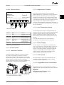
1
MAKING MODERN LIVING POSSIBLE
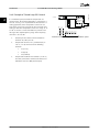
Design Guide
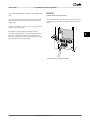
VLT® HVAC Drive FC 102 110-1400 kW
www.danfoss.com/drives
Contents
VLT® HVAC Drive FC 102 Design Guide
Contents
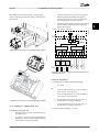
1 How to Read this Design Guide
2 Introduction
8
14
2.1 Safety
14
2.2 CE Labelling
15
2.2.1 CE Conformity and Labelling
15
2.2.2 What Is Covered
15
2.2.3 Danfoss Frequency Converter and CE Labelling
15
2.2.4 Compliance with EMC Directive 2004/108/EC
16
2.3 Air Humidity
16
2.4 Aggressive Environments
16
2.5 Vibration and Shock
17
2.6 Safe Torque Off
17
2.6.1 Electrical Terminals
17
2.6.2 Safe Torque Off Installation
17
2.6.3 Approvals & Certificates
18
2.7 Advantages
19
2.7.1 Why Use a Frequency Converter for Controlling Fans and Pumps?
19
2.7.2 The Clear Advantage - Energy Savings
19
2.7.3 Example of Energy Savings
19
2.7.4 Comparison of Energy Savings
20
2.7.5 Example with Varying Flow over 1 Year
21
2.7.6 Better Control
21
2.7.7 Cos φ Compensation
21
2.7.8 Star/Delta Starter or Soft-starter not Required
21
2.7.9 Using a Frequency Converter Saves Money
22
2.7.10 Without a Frequency Converter
22
2.7.11 With a Frequency Converter
23
2.7.12 Application Examples
24
2.7.13 Variable Air Volume
24
2.7.14 The VLT Solution
24
2.7.15 Constant Air Volume
25
2.7.16 The VLT Solution
25
2.7.17 Cooling Tower Fan
26
2.7.18 The VLT Solution
26
2.7.19 Condenser Pumps
27
2.7.20 The VLT Solution
27
2.7.21 Primary Pumps
28
2.7.22 The VLT Solution
28
MG16C102 - Rev. 2013-08-20
1
Contents
VLT® HVAC Drive FC 102 Design Guide
2.7.23 Secondary Pumps
29
2.7.24 The VLT Solution
29
2.8 Control Structures
30
2.8.1 Control Principle
30
2.8.2 Control Structure Open Loop
31
2.8.3 PM/EC+ Motor Control
31
2.8.4 Local (Hand On) and Remote (Auto On) Control
31
2.8.5 Control Structure Closed Loop
33
2.8.6 Feedback Handling
33
2.8.7 Feedback Conversion
34
2.8.8 Reference Handling
34
2.8.9 Example of Closed Loop PID Control
36
2.8.10 Programming Order
37
2.8.11 Tuning the Closed Loop Controller
38
2.8.12 Manual PID Adjustment
38
2.9 General aspects of EMC
39
2.9.1 General Aspects of EMC Emissions
39
2.9.2 Emission Requirements
40
2.9.3 EMC Test Results (Emission)
41
2.9.4 General Aspects of Harmonics Emission
42
2.9.5 Harmonics Emission Requirements
42
2.9.6 Harmonics Test Results (Emission)
42
2.9.7 Immunity Requirements
43
2.10 Galvanic Isolation (PELV)
44
2.11 Earth Leakage Current
44
2.12 Brake Function
45
2.12.1 Brake Resistor Selection
45
2.12.2 Brake Resistor Calculation
46
2.12.3 Control with Brake Function
46
2.12.4 Brake Resistor Cabling
47
2.13 Extreme Running Conditions
47
3 Selection
50
3.1 Options and Accessories
2
50
3.1.1 General Purpose Input Output Module MCB 101
50
3.1.2 Digital Inputs - Terminal X30/1-4
50
3.1.3 Analog Voltage Inputs - Terminal X30/10-12
51
3.1.4 Digital Outputs - Terminal X30/5-7
51
3.1.5 Analog Outputs - Terminal X30/5+8
51
3.1.6 Relay Option MCB 105
51
3.1.7 24 V Back-Up Option MCB 107 (Option D)
52
MG16C102 - Rev. 2013-08-20
Contents
VLT® HVAC Drive FC 102 Design Guide
3.1.8 Analog I/O Option MCB 109
53
3.1.9 VLT® PTC Thermistor Card MCB 112
54
3.1.10 Sensor Input Option MCB 114
56
3.1.10.1 Electrical and Mechanical Specifications
56
3.1.10.2 Electrical Wiring
57
3.1.11 D-frame Options
57
3.1.11.1 Load Share Terminals
57
3.1.11.2 Regeneration Terminals
57
3.1.11.3 Anti-Condensation Heater
57
3.1.11.4 Brake Chopper
57
3.1.11.5 Mains Shield
57
3.1.11.6 Ruggedized Printed Circuit Boards
57
3.1.11.7 Heat Sink Access Panel
58
3.1.11.8 Mains Disconnect
58
3.1.11.9 Contactor
58
3.1.11.10 Circuit Breaker
58
3.1.12 F-frame Panel Options
58
3.1.13 Remote Mounting Kit for LCP
59
3.1.14 Output Filters
60
4 How to Order
61
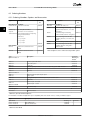
4.1 Ordering Form
61
4.2 Ordering Numbers
66
4.2.1 Ordering Numbers: Options and Accessories
66
4.2.2 Advanced Harmonic Filters
67
4.2.3 Sine-Wave Filter Modules, 380-690 V AC
73
4.2.4 Ordering Numbers: dU/dt Filters
75
4.2.5 Ordering Numbers: Brake Resistors
76
5 How to Install
77
5.1 Mechanical Installation
77
5.1.1 Mechanical Dimensions
77
5.1.2 Mechanical Dimensions, 12-Pulse Units
90
5.1.3 Mechanical Mounting
96
5.1.4 Pedestal Installation of D-frames
96
5.1.5 Pedestal Installation of F-frames
97
5.1.6 Lifting
97
5.1.7 Safety Requirements of Mechanical Installation
99
5.2 Electrical Installation
99
5.2.1 Cables General
99
5.2.2 Motor Cables
100
MG16C102 - Rev. 2013-08-20
3
Contents
VLT® HVAC Drive FC 102 Design Guide
5.2.3 Electrical Installation of Motor Cables
100
5.2.4 Preparing Gland Plates for Cables
101
5.2.5 Gland/Conduit Entry - IP21 (NEMA 1) and IP54 (NEMA12)
101
5.2.6 Gland/Conduit Entry, 12-Pulse - IP21 (NEMA 1) and IP54 (NEMA12)
105
5.2.7 Power Connections
108
5.2.8 Power Connections 12-Pulse Frequency Converters
132
5.2.9 Fuses
134
5.2.10 Fuse Specifications
134
5.2.11 Control Terminals
135
5.2.12 Control Cable Terminals
135
5.2.13 Basic Wiring Example
136
5.2.14 Electrical Installation, Control Cables
137
5.2.15 12-Pulse Control Cables
140
5.2.16 Switches S201, S202, and S801
142
5.3 Final Set-Up and Test
142
5.4 Additional Connections
144
5.4.1 Mains Disconnects
144
5.4.2 Circuit Breakers
145
5.4.3 Mains Contactors
145
5.4.4 Brake Resistor Temperature Switch
146
5.4.5 External Fan Supply
146
5.4.6 Relay Output D Frame
146
5.4.7 Relay Output E & F-Frame
147
5.5 Installation of Misc. Connections
149
5.6 Safety
150
5.6.1 High Voltage Test
150
5.6.2 Safety Earth Connection
150
5.7 EMC-correct Installation
5.7.1 Electrical Installation - EMC Precautions
151
5.7.2 Use of EMC-Correct Cables
152
5.8 Residual Current Device
6 Application Examples
154
155
6.1 Application Examples
4
151
155
6.1.1 Start/Stop
155
6.1.2 Pulse Start/Stop
155
6.1.3 Potentiometer Reference
155
6.1.4 Automatic Motor Adaptation (AMA)
156
6.1.5 Smart Logic Control
156
6.1.6 Smart Logic Control Programming
156
6.1.7 SLC Application Example
157
MG16C102 - Rev. 2013-08-20
Contents
VLT® HVAC Drive FC 102 Design Guide
6.1.8 BASIC Cascade Controller
158
6.1.9 Pump Staging with Lead Pump Alternation
159
6.1.10 System Status and Operation
159
6.1.11 Fixed Variable Speed Pump Wiring
Diagram
160
6.1.12 Lead Pump Alternation Wiring Diagram
160
6.1.13 Cascade Controller Wiring Diagram
161
6.1.14 Start/Stop Conditions
161
7 Installation and Set-up
162
7.1 Installation and Set-up
162
7.1.1 Network Connection
162
7.1.2 Hardware Setup
162
7.1.3 Parameter Settings for Modbus Communication
163
7.1.4 EMC Precautions
163
7.2 FC Protocol Overview
163
7.3 Network Configuration
164
7.4 FC Protocol Message Framing Structure
164
7.4.1 Content of a Character (byte)
164
7.4.2 Telegram Structure
164
7.4.3 Length (LGE)
165
7.4.4 Address (ADR)
165
7.4.5 Data Control Byte (BCC)
165
7.4.6 The Data Field
165
7.4.7 The PKE Field
166
7.4.8 Parameter Number (PNU)
167
7.4.9 Index (IND)
167
7.4.10 Parameter Value (PWE)
167
7.4.11 Data Types Supported by the Frequency Converter
168
7.4.12 Conversion
168
7.4.13 Process Words (PCD)
168
7.5 Examples
168
7.5.1 Writing a Parameter Value
168
7.5.2 Reading a Parameter Value
169
7.6 Modbus RTU Overview
169
7.6.1 Assumptions
169
7.6.2 Prerequisite Knowledge
169
7.6.3 Modbus RTU Overview
169
7.6.4 Frequency Converter with Modbus RTU
170
7.7 Modbus RTU Network Configuration
170
7.8 Modbus RTU Message Framing Structure
170
MG16C102 - Rev. 2013-08-20
5
Contents
VLT® HVAC Drive FC 102 Design Guide
7.8.1 Frequency Converter with Modbus RTU
170
7.8.2 Modbus RTU Message Structure
170
7.8.3 Start/Stop Field
171
7.8.4 Address Field
171
7.8.5 Function Field
171
7.8.6 Data Field
171
7.8.7 CRC Check Field
171
7.8.8 Coil Register Addressing
171
7.8.9 How to Control the Frequency Converter
173
7.8.10 Function Codes Supported by Modbus RTU
173
7.8.11 Modbus Exception Codes
174
7.9 Parameter Access
174
7.9.1 Parameter Handling
174
7.9.2 Storage of Data
174
7.9.3 IND
174
7.9.4 Text Blocks
174
7.9.5 Conversion Factor
174
7.9.6 Parameter Values
174
7.10 Examples
174
7.10.1 Read Coil Status (01 HEX)
175
7.10.2 Force/Write Single Coil (05 HEX)
175
7.10.3 Force/Write Multiple Coils (0F HEX)
175
7.10.4 Read Holding Registers (03 HEX)
176
7.10.5 Preset Single Register (06 HEX)
176
7.10.6 Preset Multiple Registers (10 HEX)
177
7.11 Danfoss FC Control Profile
8 General Specifications and Troubleshooting
8.1 General Specifications
6
178
183
183
8.1.1 Mains Supply 3x380-480 V AC
183
8.1.2 Mains Supply 3x525-690 V AC
185
8.1.3 12-Pulse Specifications
188
8.2 Efficiency
194
8.3 Acoustic Noise
194
8.4 Peak Voltage on Motor
195
8.5 Special Conditions
196
8.5.1 Purpose of Derating
196
8.5.2 Derating for Ambient Temperature
196
8.5.3 Automatic Adaptations to Ensure Performance
197
8.5.4 Derating for Low Air Pressure
197
8.5.5 Derating for Running at Low Speed
198
MG16C102 - Rev. 2013-08-20
Contents
VLT® HVAC Drive FC 102 Design Guide
8.6 Troubleshooting
198
8.6.1 Alarm Words
203
8.6.2 Warning Words
204
8.6.3 Extended Status Words
205
8.6.4 Warning and Alarm Introduction
205
Index
212
MG16C102 - Rev. 2013-08-20
7
1 1
How to Read this Design Gui...
VLT® HVAC Drive FC 102 Design Guide
1 How to Read this Design Guide
result of lost profits or revenue, loss or damage of
equipment, loss of computer programs, loss of data, the
costs to substitute these, or any claims by third parties.
1.1 How to Read This Design Guide
VLT® HVAC Drive
FC 102 Series
Danfoss reserves the right to revise this publication at any
time and to change its contents without prior notice or
any obligation to notify former or present users of such
revisions or changes.
1.1.1 Available Literature
This guide can be used with all
VLT® HVAC Drive frequency
converters with software version
3.9x.
The full software version number
can be read from
ID-43 Software Version.
Table 1.1 Software Version Information
This contains information proprietary to Danfoss. By
accepting and using this manual, the reader agrees that
the information contained herein will be used solely for
operating units from Danfoss or equipment from other
vendors provided that such equipment is intended for
communication with Danfoss units over a serial communication link. This publication is protected under the
copyright laws of Denmark and most other countries.
Danfoss does not warrant that a software program
produced according to the guidelines provided in this
manual functions properly in every physical, hardware, or
software environment.
•
The VLT® HVAC Drive Operating Instructions are
shipped with the unit and include information on
installation and startup.
•
The VLT® HVAC Drive Design Guide includes all
technical information about the frequency
converter, frames D, E, and F, and customer
design and applications.
•
The VLT® HVAC Drive Programming Guide provides
information on how to programme and includes
complete parameter descriptions.
•
•
Application Note, Temperature Derating Guide.
•
Danfoss VLT® Energy Box software at
www.danfoss.com/BusinessAreas/DrivesSolutions/
Softwaredownload/
•
•
•
Operating Instructions VLT® HVAC Drive BACnet.
PC-based configuration tool MCT 10, enables
configuration the frequency converter from a
Windows™ based PC environment.
Operating Instructions VLT® HVAC Drive Metasys.
Operating Instructions VLT® HVAC Drive FLN.
Danfoss technical literature is available in print from local
Danfoss sales offices or online at:
www.danfoss.com/BusinessAreas/DrivesSolutions/Documentations/VLT+Technical+Documentation.htm
Although Danfoss has tested and reviewed the documentation within this manual, Danfoss makes no warranty or
representation, neither expressed nor implied, with respect
to this documentation, including its quality, performance,
or fitness for a particular purpose.
In no event shall Danfoss be liable for direct, indirect,
special, incidental, or consequential damages arising out of
the use, or the inability to use information contained in
this manual, even if advised of the possibility of such
damages. In particular, Danfoss is not responsible for any
costs, including but not limited to those incurred as a
8
MG16C102 - Rev. 2013-08-20
How to Read this Design Gui...
VLT® HVAC Drive FC 102 Design Guide
1.1.2 Approvals
Table 1.2 Compliance Marks: CE, UL, and C-Tick
Alternating current
AC
American wire gauge
AWG
Ampere/AMP
A
Automatic Motor Adaptation
AMA
Current limit
ILIM
Degrees Celsius
°C
Direct current
DC
Drive Dependent
D-TYPE
Electro Magnetic Compatibility
EMC
Electronic Thermal Relay
ETR
Frequency converter
FC
Gram
g
The frequency converter complies with UL508C thermal
memory retention requirements. For more information,
refer to2.13.1 Motor Thermal Protection .
Hertz
Hz
Horsepower
hp
Kilohertz
kHz
The following symbols are used in this document.
Local Control Panel
LCP
Meter
m
Millihenry Inductance
mH
Milliampere
mA
WARNING
Indicates a potentially hazardous situation which could
result in death or serious injury.
CAUTION
Indicates a potentially hazardous situation which could
result in minor or moderate injury. It may also be used
to alert against unsafe practices.
Millisecond
ms
Minute
min
Motion Control Tool
MCT
Nanofarad
nF
Newton Meters
Nm
Nominal motor current
IM,N
Nominal motor frequency
fM,N
Nominal motor power
PM,N
NOTICE
Nominal motor voltage
UM,N
Indicates important information, including situations that
may result in damage to equipment or property.
Permanent Magnet motor
PM motor
Protective Extra Low Voltage
PELV
Printed Circuit Board
PCB
Rated Inverter Output Current
IINV
Revolutions Per Minute
RPM
Regenerative terminals
Regen
Second
sec.
Synchronous Motor Speed
ns
Torque limit
TLIM
Volts
V
The maximum output current
IVLT,MAX
The rated output current supplied by the
frequency converter
IVLT,N
1 1
Table 1.3 Abbreviations used in this Manual
MG16C102 - Rev. 2013-08-20
9
VLT® HVAC Drive FC 102 Design Guide
1.1.3 Definitions
PM,N
The rated motor power (nameplate data).
drive:
TM,N
The rated torque (motor).
IVLT,MAX
The maximum output current.
IVLT,N
The rated output current supplied by the frequency
converter.
UVLT, MAX
The maximum output voltage.
UM,N
The rated motor voltage (nameplate data).
break-away torque:
input:
Control command
Start and stop the
UM
The instantaneous motor voltage.
ns
Synchronous motor speed.
Group Reset, coasting stop, reset
1
and coasting stop, quick-
connected motor with the
stop, DC braking, stop and
LCP or the digital inputs.
the "Off" key.
Functions are divided into Group Start, pulse start, reversing,
two groups.
2
start reversing, jog, and
Functions in group 1 have
freeze output.
higher priority than
functions in group 2.
ns =
2 × par . 1 − 23 × 60 s
par . 1 − 39
Torque
175ZA078.10
1 1
How to Read this Design Gui...
Pull-out
Table 1.4 Input Functions
motor:
fJOG
The motor frequency when the jog function is activated
(via digital terminals).
fM
The motor frequency.
fMAX
The maximum motor frequency.
fMIN
The minimum motor frequency.
fM,N
The rated motor frequency (nameplate data).
IM
The motor current.
IM,N
The rated motor current (nameplate data).
rpm
Illustration 1.1 Break-Away Torque Chart
ηVLT
The efficiency of the frequency converter is defined as the
ratio between the power output and the power input.
start-disable command
A stop command belonging to the group 1 control
commands.
stop command
See control commands parameter group.
references:
analog reference
A signal transmitted to the 53 or 54, can be voltage or
current.
nM,N
The rated motor speed (nameplate data).
10
MG16C102 - Rev. 2013-08-20
How to Read this Design Gui...
VLT® HVAC Drive FC 102 Design Guide
binary reference
A signal applied to the serial communication port (FS-485
terminal 68-69).
CT characteristics
Constant torque characteristics used for screw and scroll
refrigeration compressors.
bus reference
A signal transmitted to the serial communication port (FC
port).
digital inputs
The digital inputs can be used for controlling various
functions of the frequency converter.
preset reference
A defined preset reference set from -100% to +100% of
the reference range. Selection of eight preset references
via the digital terminals.
digital outputs
The frequency converter features two solid state outputs
that can supply a 24 V DC (max. 40 mA) signal.
pulse reference
A pulse frequency signal transmitted to the digital inputs
(terminal 29 or 33).
refMAX
Determines the relationship between the reference input
at 100% full scale value (typically 10 V, 20 mA) and the
resulting reference. The maximum reference value is set in
F-53 Maximum Reference.
refMIN
Determines the relationship between the reference input
at 0% value (typically 0 V, 0 mA, 4 mA) and the resulting
reference. The minimum reference value is set in
F-52 Minimum Reference.
1 1
DSP
Digital Signal Processor.
relay outputs:
The frequency converter features two programmable relay
outputs.
ETR
Electronic thermal relay is a thermal load calculation based
on present load and time. Its purpose is to estimate the
motor temperature.
GLCP:
Graphical local control panel (LCP102)
Hiperface®
Hiperface® is a registered trademark by Stegmann.
miscellaneous:
analog inputs
The analog inputs are used for controlling various
functions of the frequency converter.
There are two types of analog inputs:
Current input, 0–20 mA, and 4–20 mA
Voltage input, 0–10 V DC.
analog outputs
The analog outputs can supply a signal of 0–20 mA, 4–20
mA, or a digital signal.
automatic motor adaptation, AMA
AMA algorithm determines the electrical parameters for
the connected motor at standstill.
brake resistor
The brake resistor is a module capable of absorbing the
brake power generated in regenerative braking. This
regenerative braking power increases the intermediate
circuit voltage and a brake chopper ensures that the
power is transmitted to the brake resistor.
initialising
If initialising is carried out (H-03 Restore Factory Settings),
the programmable parameters of the frequency converter
return to their default settings.
intermittent duty cycle
An intermittent duty rating refers to a sequence of duty
cycles. Each cycle consists of an on-load and an off-load
period. The operation can be either periodic duty or noneperiodic duty.
LCP
The local control panel (LCP) keypad makes up a complete
interface for control and programming of the frequency
converter. The control panel keypad is detachable and can
be installed up to 3 metres from the frequency converter,
in a front panel with the installation kit option.
The local control panel is available in two versions:
•
•
Numerical LCP101 (NLCP)
Graphical LCP102 (GLCP)
lsb
Least significant bit.
MG16C102 - Rev. 2013-08-20
11
1 1
How to Read this Design Gui...
VLT® HVAC Drive FC 102 Design Guide
MCM
Short for mille circular mil, an American measuring unit for
cable cross-section. 1 MCM ≡ 0.5067 mm2.
msb
Most significant bit.
smart logic control (SLC)
The SLC is a sequence of user-defined actions executed
when the associated user-defined events are evaluated as
true by the SLC.
STW
Status word.
NLCP
Numerical local control panel LCP101.
on-line/off-line parameters
Changes to on-line parameters are activated immediately
after the data value is changed. Changes to off-line
parameters are not activated until [OK] is entered on the
LCP.
PID controller
The PID controller maintains the desired speed, pressure
and temperature by adjusting the output frequency to
match the varying load.
PCD
Process Data.
pulse input/incremental encoder
An external digital sensor used for feedback information of
motor speed and direction. Encoders are used for highspeed accuracy feedback and in high dynamic applications.
The encoder connection is either via terminal 32 or
encoder option MCB 102.
RCD
Residual Current Device. A device that disconnects a circuit
in case of an imbalance between an energised conductor
and ground. Also known as a ground fault circuit
interrupter (GFCI).
set-up
Parameter settings can be saved in four set-ups. Change
between the four parameter set-ups and edit one set-up,
while another set-up is active.
SFAVM
Switching pattern called Stator Flux oriented Asynchronous
Vector Modulation (F-37 Adv. Switching Pattern).
slip compensation
The frequency converter compensates for the motor slip
by giving the frequency a supplement that follows the
measured motor load, keeping the motor speed almost
constant.
thermistor
A temperature-dependent resistor placed where the
temperature is monitored (frequency converter or motor).
THD
Total Harmonic Distortion. A state of full harmonic
distortion.
trip
A state entered in fault situations. For example, if the
frequency converter is subject to an overtemperature or
when it is protecting the motor, process, or mechanism.
Restart is prevented until the cause of the fault has
disappeared and the trip state is cancelled by activating
Reset or, in some cases, by being programmed to reset
automatically. Do not use trip for personal safety.
trip locked
A state entered in fault situations when the frequency
converter is protecting itself and requires physical
intervention. For example, if the frequency converter is
subject to a short circuit on the output, it will enter trip
lock. A locked trip can only be cancelled by cutting off
mains, removing the cause of the fault, and reconnecting
the frequency converter.
VT characteristics
Variable torque characteristics used for pumps and fans.
VVCplus
If compared with standard voltage/frequency ratio control,
Voltage Vector Control (VVCplus) improves the dynamics
and the stability, both when the speed reference is
changed and in relation to the load torque.
60°° AVM
Switching pattern called 60°Asynchronous Vector
Modulation (See F-37 Adv. Switching Pattern).
The power factor is the relation between I1 and IRMS.
Power factor =
3 × U × I1 × COS ϕ
3 × U × IRMS
The power factor for 3-phase control:
=
12
I1 × cos ϕ1
I1
=
since cos ϕ1 = 1
IRMS
IRMS
MG16C102 - Rev. 2013-08-20
How to Read this Design Gui...
VLT® HVAC Drive FC 102 Design Guide
1 1
The power factor indicates to what extent the frequency
converter imposes a load on the mains supply.
The lower the power factor, the higher the IRMS for the
same kW performance.
IRMS = I12 + I52 + I72 + . . + In2
In addition, a high power factor indicates that the different
harmonic currents are low.
The built-in DC coils produce a high power factor, which
minimizes the imposed load on the mains supply.
MG16C102 - Rev. 2013-08-20
13
Introduction
VLT® HVAC Drive FC 102 Design Guide
2 Introduction
2 2
DC intermediate circuit) and external 24 V DC are
present. Check that all voltage inputs have been
disconnected and that the necessary time has
passed before commencing repair work.
2.1 Safety
2.1.1 Safety Note
Installation at High Altitudes
WARNING
WARNING
The voltage of the frequency converter is dangerous
whenever connected to mains. Incorrect installation of
the motor, frequency converter, or fieldbus could
damage the units or cause serious personal injury or
death. The instructions in this manual, as well as national
and local rules and safety regulations, must be complied
with.
For installation in altitudes above 3 km (350–500 V), or 2
km (525–690 V), contact Danfoss regarding PELV.
Warning against unintended start
1.
The motor can be stopped while connected to
mains in the following ways:
•
•
•
•
Safety Regulations
1.
2.
3.
4.
5.
Check that the mains supply has been disconnected and that the necessary time has passed
before removing motor and mains plugs.
Do not use [Stop/Reset] as a safety switch. It does
not disconnect the unit from mains.
Establish correct protective earth of the
unit
•
Protect the operator against supply
voltage
•
Protect the motor against overload
NOTICE
The function is initialised at 1.16 x rated motor current
and rated motor frequency. For the North American
market: The ETR functions provide class 20 motor
overload protection in accordance with NEC.
6.
Do not remove the plugs for the motor and
mains supply while the frequency converter is
connected to mains. Check that the mains supply
has been disconnected and that the necessary
time has passed before removing motor and
mains plugs.
7.
14
The frequency converter has more voltage inputs
than L1, L2, and L3, when load sharing (linking of
references
local stop
2.
While parameters are being changed, the motor
could start. Always activate [Stop/Reset] before
modifying data.
3.
A stopped motor can restart if the following
conditions occur:
Ensure that the earth leakage currents are higher
than 3.5 mA.
Protection against motor overload comes from
1-90 Motor Thermal Protection. If this function is
desired, set 1-90 Motor Thermal Protection to data
value [4] ETR trip (default value) or data value [3]
ETR warning.
bus commands
Unintended start can still occur.
In accordance with applicable national and local
regulations:
•
digital commands
•
A fault in the electronics of the
frequency converter
•
•
•
A temporary overload
A fault in the supply mains
A disruption in the motor connection
Refer to the Operating Instructions for further safety
guidelines.
WARNING
Discharge Time
Frequency converters contain DC-link capacitors that can
remain charged even when the frequency converter is
not powered. To avoid electrical hazards, take the
following precautions:
•
•
•
Disconnect AC mains
Disconnect any permanent magnet motors
Disconnect any remote DC-link power supplies,
including battery backups, UPS, and DC-link
connections to other units
Failure to wait the specified time after power has been
removed before doing service or repair could result in
death or serious injury. See Table 2.1 for discharge times.
MG16C102 - Rev. 2013-08-20
Introduction
VLT® HVAC Drive FC 102 Design Guide
Rating [kW]
380–480 V
110–315
20 minutes
45–400
315–1000
525–690 V
20 minutes
40 minutes
450–1200
In addition, we specify which standards our products
comply with. We offer the filters presented in the specifications and provide other types of assistance to ensure the
optimum EMC result.
30 minutes
Trade professionals use the frequency converter as a
complex component forming part of a larger appliance,
system, or installation. The responsibility for the final EMC
properties of the appliance, system, or installation rests
with the installer.
Table 2.1 DC Capacitor Discharge Times
2.1.2 Disposal Instruction
Do not dispose of equipment containing
electrical components together with
domestic waste.
Collect it separately in accordance with
local and currently valid legislation.
Table 2.2 Disposal Instruction
2.2 CE Labelling
2.2.2 What Is Covered
The EU "Guidelines on the Application of Council Directive
2004/108/EC" outline three typical situations for using a
frequency converter. See 2.2.3 Danfoss Frequency Converter
and CE Labelling and 2.2.4 Compliance with EMC Directive
2004/108/EC for CE labelling and EMC coverage.
1.
The frequency converter is sold directly to the
end-consumer. The frequency converter is for
example sold to a DIY market. The end-consumer
is a layman who uses the frequency converter
with a hobby machine, or household appliance.
For such applications, the frequency converter
must be CE labelled in accordance with the EMC
directive.
2.
The frequency converter is sold for installation in
a plant, such as a production plant or a heating/
ventilation plant designed and installed by trade
professionals. The frequency converter and the
finished plant do not have to be CE labelled
under the EMC directive. However, the unit must
comply with the basic EMC requirements of the
directive. Use components, appliances, and
systems that are CE labelled under the EMC
directive.
3.
The frequency converter is sold as part of a
complete system, such as an air-conditioning
system. The system is marketed as complete. The
complete system must be CE labelled in
accordance with the EMC directive. The
manufacturer can ensure CE labelling under the
EMC directive either by using CE labelled
components or by testing the EMC of the system.
The entire system need not be tested when only
CE labelled components are used.
2.2.1 CE Conformity and Labelling
What is CE conformity and labelling?
The purpose of CE labelling is to avoid technical trade
obstacles within EFTA and the EU. The EU has introduced
the CE label as a simple way of showing whether a
product complies with the relevant EU directives. The CE
label says nothing about the specifications or quality of
the product. Frequency converters follow three EU
directives:
The machinery directive (2006/42/EC)
Frequency converters with integrated safety function are
now falling under the machinery directive. Danfoss CElabels in accordance with the directive and issues a
declaration of conformity upon request. Frequency
converters without safety function do not fall under the
machinery directive. However, if a frequency converter is
supplied for use in a machine, we provide information on
safety aspects relating to the frequency converter.
The low-voltage directive (2006/95/EC)
Frequency converters must be CE labelled in accordance
with the low-voltage directive of January 1, 1997. The
directive applies to all electrical equipment and appliances
used in the 50–1000 V AC and the 75–1500 V DC voltage
ranges. Danfoss CE-labels in accordance with the directive
and issues a declaration of conformity upon request.
The EMC directive (2004/108/EC)
EMC is short for electromagnetic compatibility. The
presence of electromagnetic compatibility means that the
mutual interference between different components/
appliances does not affect the way the appliances work.
The EMC directive came into effect January 1, 1996.
Danfoss CE-labels in accordance with the directive and
issues a declaration of conformity upon request. To carry
out EMC-correct installation, see 5.7 EMC-correct Installation.
2.2.3 Danfoss Frequency Converter and CE
Labelling
CE labelling is a positive feature when used for its original
purpose: To facilitate trade within the EU and EFTA.
MG16C102 - Rev. 2013-08-20
15
2 2
2 2
Introduction
VLT® HVAC Drive FC 102 Design Guide
However, CE labelling could cover many different specifications, so check the specifics of each CE label.
Danfoss CE labels the frequency converters in accordance
with the low-voltage directive. If the frequency converter is
installed correctly, compliance with the low-voltage
directive is guaranteed. Danfoss issues a declaration of
conformity that confirms our CE labelling in accordance
with the low-voltage directive.
The CE label also applies to the EMC directive if the
instructions for EMC-correct installation and filtering are
followed. On this basis, a declaration of conformity in
accordance with the EMC directive is issued.
For more on EMC, refer to 5.7 EMC-correct Installation.
Danfoss provides other types of assistance to obtain the
best EMC result.
2.2.4 Compliance with EMC Directive
2004/108/EC
Trade professionals use the frequency converter as a
complex component forming part of a larger appliance,
system, or installation. The responsibility for the final EMC
properties of the appliance, system, or installation rests
with the installer. As an aid to the installer, Danfoss has
prepared EMC installation guidelines for the power drive
system. Following EMC-correct installation instructions
ensures compliance with standards and test levels stated
for power drive systems. See 2.9 General aspects of EMC.
The frequency converter has been designed to meet the
IEC/EN 60068-2-3 standard, EN 50178 § 9.4.2.2 at 50 °C.
2.4 Aggressive Environments
A frequency converter contains many mechanical and
electronic components. All are to some extent vulnerable
to environmental effects.
CAUTION
Do not install the frequency converter in environments
with airborne liquids, particles, or gases capable of
affecting and damaging the electronic components.
Failure to take the necessary protective measures
increases the risk of stoppages, thus reducing the life of
the frequency converter.
16
Liquids can be carried through the air and condense in the
frequency converter and may cause corrosion of
components and metal parts. Steam, oil, and salt water can
corrode components and metal parts. In such
environments, use equipment with enclosure rating IP
54/55. As an extra protection, coated printed circuit boards
can be ordered as an option.
Airborne Particles such as dust can cause mechanical,
electrical, or thermal failure in the frequency converter. A
typical indicator of excessive levels of airborne particles is
dust particles around the frequency converter fan. In dusty
environments, use equipment with enclosure rating IP
54/55 (NEMA 12) or an enclosure for IP 00/IP 20 (NEMA 1)
equipment.
In environments with high temperatures and humidity,
corrosive gases, such as sulphur, nitrogen, and chlorine
compounds cause chemical processes on the frequency
converter components.
Such chemical reactions rapidly damage the electronic
components. In such environments, mount the unit in an
enclosure with fresh air ventilation, keeping aggressive
gases away from the frequency converter.
Optional coating of printed circuit boards provides extra
protection in such areas.
NOTICE
2.3 Air Humidity
Degree of protection as per IEC 60529
Install the safe torque off function only in an enclosure
with an IP54 or higher rating (or equivalent environment).
Doing so will avoid cross faults and short circuits between
terminals, connectors, tracks, and safety-related circuitry
caused by foreign objects.
Mounting frequency converters in aggressive
environments increases the risk of stoppages and considerably reduces the life of the unit.
Before installing the frequency converter, observe existing
installations in the environment to check the ambient air
for liquids, particles, and gases. Typical indicators of
harmful airborne liquids are water, oil, or corrosion on
metal parts.
Excessive dust particle levels are often found on installation enclosures and existing electrical installations. One
indicator of aggressive airborne gases is blackening of
copper rails and cable ends on existing installations.
D and E enclosures have a stainless steel back-channel
option to provide more protection in aggressive
environments. Proper ventilation is still required for the
internal components of the drive. Contact Danfoss for
more information.
MG16C102 - Rev. 2013-08-20
Introduction
VLT® HVAC Drive FC 102 Design Guide
not sufficient. Remove it entirely to avoid shortcircuiting. See jumper in Illustration 2.1.
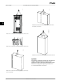
2.5 Vibration and Shock
2.
The frequency converter has been tested according to the
procedure based on the following standards:
•
•
130BT314.10
The frequency converter complies with requirements for
units mounted on the walls and floors of production
premises, as well as in panels bolted to walls or floors.
Connect terminal 37 to 24 V DC by a short-circuit
protected cable. The 24 V DC voltage supply
must be interruptible by an EN954-1 Category 3
circuit interrupt device. If the interrupt device and
the frequency converter are placed in the same
installation panel, use an unscreened cable
instead of a screened one.
IEC/EN 60068-2-6: Vibration (sinusoidal) - 1970
IEC/EN 60068-2-64: Vibration, broad-band random
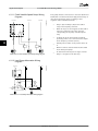
2.6 Safe Torque Off
2.6.1 Electrical Terminals
The frequency converter can perform the safety function
Safe Torque Off (As defined by draft CD IEC 61800-5-2) or
stop Category 0 (as defined in EN 60204-1).
It is designed and approved suitable for the requirements
of Safety Category 3 in EN 954-1. . Before integration and
use of safe torque off in an installation, perform a
thorough risk analysis on the installation to determine
whether the safe torque off functionality and safety
category are sufficient.
Typical reaction time for terminal 37 is <10 ms.
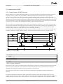
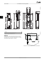
12
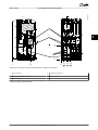
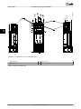
37
Illustration 2.1 Bridge Jumper Between Terminal 37 and 24 V
DC
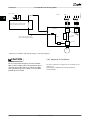
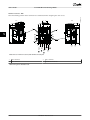
2.6.2 Safe Torque Off Installation
To carry out an installation of a Category 0 stop
(EN60204) in conformity with Safety Category 3
(EN954-1), follow these instructions:
1.
Remove the bridge (jumper) between terminal 37
and 24 V DC. Cutting or breaking the jumper is
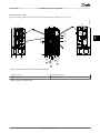
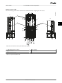
Illustration 2.2 shows a stopping category 0 (EN 60204-1)
with safety Category 3 (EN 954-1). An opening door
contact causes the circuit interrupt. The illustration also
shows how to connect a non-safety related hardware
coast.
MG16C102 - Rev. 2013-08-20
17
2 2
VLT® HVAC Drive FC 102 Design Guide
Door contact
130BB566.10
Introduction
Mains
6 phase
Coast
2 2
Safety device Cat.3 (Circuit interrupt
device, possibly with release input)
12
Frequency
Converter
R1
R2
37
Rec
Safe
channel
Shor t-circuit protected cable
(if not inside installation cabinet)
Control
board
5Vdc
Inverter
M
Illustration 2.2 Installation with Stopping Category 0 and Safety Category 3
2.6.3 Approvals & Certificates
CAUTION
IT Mains
Do not connect 400 V frequency converters with RFIfilters to mains supplies with a voltage between phase
and earth of more than 440 V. For IT mains and delta
earth (grounded leg), mains voltage can exceed 440 V
between phase and earth.
18
The latest certificates and approvals are available on the
Internet, see
www.danfoss.com/BusinessAreas/DrivesSolutions/
Documentations
MG16C102 - Rev. 2013-08-20
Introduction
VLT® HVAC Drive FC 102 Design Guide
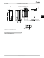
2.7.1 Why Use a Frequency Converter for
Controlling Fans and Pumps?
130BA780.10
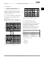
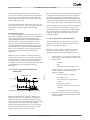
2.7 Advantages
120
A
SYSTEM CURVE
A frequency converter takes advantage of the fact that
centrifugal fans and pumps follow the laws of proportionality for such applications. For further information, see
2.7.3 Example of Energy Savings.
PRESSURE%
100
80
FAN CURVE
B
60
40
C
2.7.2 The Clear Advantage - Energy Savings
130BA781.10
The clear advantage of using a frequency converter for
controlling the speed of fans or pumps lies in the
electricity savings.
When comparing with alternative control systems and
technologies, a frequency converter is the optimum energy
control system for controlling fan and pump systems.
120
A
SYSTEM CURVE
100
PRESSURE %
80
FAN CURVE
B
60
40
20
0
20
40
60
80
100 120
VOLUME%
140
160
180
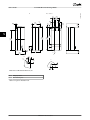
Illustration 2.4 Fan Curves for Reduced Fan Volumes.
2.7.3 Example of Energy Savings
As seen in Illustration 2.5, the flow is controlled by
changing the RPM. Reducing the speed only 20% from the
rated speed also reduces the flow by 20%. The flow is
directly proportional to the RPM. The consumption of
electricity, however, is reduced by 50%.
If the system only runs at 100% flow a few days per year,
while the average is below 80% of the rated flow, the
amount of energy saved is even more than 50%.
C
20
0
20
40
60
80 100
Voume %
120
140
160
180
120
INPUT POWER %
100
80
P = Power
Q1 = Rated flow
P1 = Rated power
Q2 = Reduced flow
P2 = Reduced power
H = Pressure
n = speed control
H1 = Rated pressure
n1 = Rated speed
H2 = Reduced pressure
n2 = Reduced speed
Q1
n1
=
Q2
n2
H1
n1 2
Pressure:
=
H2
n2
P1
n1 3
Power:
=
P2
n2
Flow:
40
0
Q = Flow
Table 2.3 Laws of Proportionality
60
20
Illustration 2.5 describes the dependence of flow, pressure, and
power consumption on RPM.
ENERGY
CONSUMED
20
40
60
80
100
Voume %
120
140
160
180
( )
( )
Illustration 2.3 Energy Saved with Reduced Fan Capacity
MG16C102 - Rev. 2013-08-20
19
2 2
VLT® HVAC Drive FC 102 Design Guide
100%
2 2
80%
50%
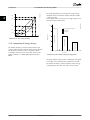
The graph (Illustration 2.6) shows typical energy savings
obtainable with 3 well-known solutions when fan volume
is reduced to 60%.
As the graph shows, more than 50% energy savings can be
achieved in typical applications.
130BA779.11
175HA208.10
Introduction
Flow ~n
100
Pressure ~n2
Discharge Damper Solution
25%
IGV Solution
80
VLT Solution
Power ~n3
40
2.7.4 Comparison of Energy Savings
20
The Danfoss frequency converter solution offers major
savings compared with traditional energy saving solutions.
The frequency converter is able to control fan speed
according to thermal load on the system and it has the
ability to function as a Building Management System
(BMS).
Energy consumed
Illustration 2.5 Laws of Proportionality
60
Energy consumed
80% 100%
Energy consumed
n
50%
Input power %
12,5%
0
0
60
0
60
0
60
Volume %
Illustration 2.6 Three Common Energy Saving Systems
Discharge dampers reduce power consumption. Inlet guide
vanes offer a 40% reduction but are expensive to install.
The Danfoss frequency converter solution reduces energy
consumption by more than 50% and is easy to install.
20
MG16C102 - Rev. 2013-08-20
Introduction
VLT® HVAC Drive FC 102 Design Guide
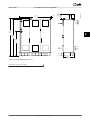
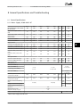
2.7.5 Example with Varying Flow over 1
Year
Energy savings
Pshaft=Pshaft output
2 2
Table 2.4 is based on pump characteristics obtained from a
pump datasheet.
The result obtained shows energy savings in excess of 50%
at the given flow distribution over a year. The pay back
period depends on the price per kWh and the price of
frequency converter. In this example, it is less than a year
when compared with valves and constant speed.
m3/h
Distribution
%
Table 2.4 Flow Distribution Over One Year
Valve regulation
Hours
Control
Power
Consumption
Power
A1 - B1
kWh
A1 - C1
Consumption
kWh
18.615
350
5
438
42,5
18.615
42,5
300
15
1314
38,5
50.589
29,0
38.106
250
20
1752
35,0
61.320
18,5
32.412
200
20
1752
31,5
55.188
11,5
20.148
150
20
1752
28,0
49.056
6,5
11.388
100
20
1752
23,0
40.296
3,5
Σ
100
8760
275.064
6.132
26.801
175HA209.11
Table 2.5 Energy Savings Calculation
Hs
(mwg)
60
50
B
40
Furthermore, a frequency converter can quickly adapt the
speed of the fan or pump to new flow or pressure
conditions in the system.
Simple control of process (flow, level or pressure) utilising
the built-in PID control.
30
A
2.7.7 Cos φ Compensation
1650rpm
20
1350rpm
C
10
1050rpm
750rpm
0
100
200
300
400
(m3 /h)
Pshaft
(kW)
60
Typically, the VLT® HVAC Drive has a cos φ of 1 and
provides power factor correction for the cos φ of the
motor, which means there is no need to make allowance
for the cos φ of the motor when sizing the power factor
correction unit.
50
A1
2.7.8 Star/Delta Starter or Soft-starter not
Required
1650rpm
40
30
1350rpm
B1
20
10
1050rpm
C1
750rpm
0
100
200
300
400 (m3 /h)
Illustration 2.7 Energy Savings in a Pump Application
When larger motors are started, it is necessary in many
countries to use equipment that limits the start-up current.
In more traditional systems, a star/delta starter or softstarter is widely used. Such motor starters are not required
if a frequency converter is used.
As illustrated in Illustration 2.8, a frequency converter does
not consume more than rated current.
2.7.6 Better Control
If a frequency converter is used for controlling the flow or
pressure of a system, improved control is obtained.
A frequency converter can vary the speed of the fan or
pump, obtaining variable control of flow and pressure.
MG16C102 - Rev. 2013-08-20
21
Introduction
VLT® HVAC Drive FC 102 Design Guide
700
2 2
1 = VLT® HVAC Drive
175HA227.10
800
2 = Star/delta starter
3 = Soft-starter
600
4 = Start directly on mains
4
% Full load current
500
Table 2.6 Legend to Illustration 2.8
400
300
3
200
2.7.9 Using a Frequency Converter Saves
Money
2
100
1
The frequency converter eliminates the need for some
equipment that would normally be used. It is possible to
calculate the cost of installing the two different systems.
The two systems shown in Illustration 2.9 and
Illustration 2.10 can be established at roughly the same
price.
0
0
12,5
25
37,5
50Hz
Full load
& speed
Illustration 2.8 Current Consumption with a Frequency
Converter
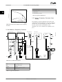
2.7.10 Without a Frequency Converter
Heating section
-
Return
Control
Valve
position
Bypass
Fan section
Supply
air
Fan
M
+
Flow
3-Port
valve
Return
Inlet guide vane
V.A.V
Sensors
PT
Flow
3-Port
valve
outlets
Control
Mechanical
linkage
and vanes
Valve
position
Bypass
x6
Pump
M
Pump
M
x6
x6
IGV
Motor
or
actuator
Duct
Starter
Starter
Local
D.D.C.
control
Starter
Main
B.M.S
Control
Fuses
Fuses
LV
supply
P.F.C
LV
supply
P.F.C
Mains
Mains
Power
Factor
Correction
Mains
Illustration 2.9 Traditional Fan System
DDC
Direct Digital Control
VAV
Variable Air Volume
Sensor P
Pressure
EMS
Energy Management System
Sensor T
Temperature
Table 2.7 Legend to Illustration 2.9
22
MG16C102 - Rev. 2013-08-20
Pressure
control
signal
0/10V
Temperature
control
signal
0/10V
175HA205.12
Cooling section
Introduction
VLT® HVAC Drive FC 102 Design Guide
Cooling section
Heating section
Fan section
+
Fan
M
-
Return
Flow
Return
Supply
air
Sensors
PT
V.A.V
outlets
175HA206.11
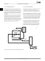
2.7.11 With a Frequency Converter
Flow
x3
M
VLT
Pump
x3
M
Duct
Pump
x3
VLT
Control
temperature
0-10V
or
Mains 0/4-20mA Mains
VLT
Pressure
control
0-10V
or
0/4-20mA
Local
D.D.C.
control
Main
B.M.S
Control
temperature
0-10V
or
0/4-20mA
Mains
Illustration 2.10 Fan System Controlled by Frequency Converters
MG16C102 - Rev. 2013-08-20
23
2 2
VLT® HVAC Drive FC 102 Design Guide
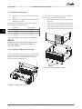
2.7.12 Application Examples
The next few pages give typical examples of applications
within HVAC.
For further information about a given application, consult
the Danfoss supplier for an application note that gives a
full description of the application.
considered to be the most energy efficient method to air
condition buildings. Central systems are more efficient
than distributed systems.
The efficiency comes from using larger fans and chillers,
which have higher efficiencies than small motors and
distributed air-cooled chillers. Savings are also realised
from the decreased maintenance requirements.
•
Variable Air Volume: Improving VAV Ventilation
Systems
2.7.14 The VLT Solution
•
Constant Air Volume: Improving CAV Ventilation
Systems
•
Cooling Tower Fan: Improving Fan Control on
Cooling Towers
•
Condenser Pumps: Improving Condenser Water
Pumpting Systems
•
Primary Pumps: Improving Primary Pumping in
Pri/Sec System
•
Secondary Pumps: Improving Secondary Pumping
in Pri/Sec System
While dampers and IGVs work to maintain a constant
pressure in the ductwork, a frequency converter solution
saves more energy and reduces the complexity of the
installation. Instead of creating an artificial pressure drop
or a decrease in fan efficiency, the frequency converter
decreases the speed of the fan to provide the flow and
pressure required by the system.
Centrifugal devices such as fans decrease the pressure and
flow they produce as their speed is reduced. Their power
consumption is reduced.
The return fan is frequently controlled to maintain a fixed
difference in airflow between the supply and return. The
advanced PID controller of the HVAC frequency converter
can be used to eliminate the need for more controllers.
2.7.13 Variable Air Volume
VAV or variable air volume systems, are used to control
both the ventilation and temperature to satisfy the
requirements of a building. Central VAV systems are
Cooling coil
Heating coil
Filter
Frequency
converter
130BB455.10
2 2
Introduction
Pressure
signal
VAV boxes
Supply fan
D1
3
T
Flow
D2
Frequency
converter
Return fan
3
D3
Illustration 2.11 Frequency Converters Used in a VAV System
24
MG16C102 - Rev. 2013-08-20
Flow
Pressure
transmitter
VLT® HVAC Drive FC 102 Design Guide
2.7.15 Constant Air Volume
setpoint or fixed difference between the supply and return
air flows.
CAV, or constant air volume systems are central ventilation
systems used to supply large common zones with the
minimum amounts of fresh tempered air. They preceded
VAV systems and are found in older multi-zoned
commercial buildings as well. These systems preheat fresh
air with air handling units (AHUs) that have heating coils.
Many are also used for air conditioning buildings and have
a cooling coil. Fan coil units are often used to help with
the heating and cooling requirements in the individual
zones.
2.7.16 The VLT Solution
With a frequency converter, significant energy savings can
be obtained while maintaining decent control of the
building. Temperature sensors or CO2 sensors can be used
as feedback signals to frequency converters. Whether
controlling temperature, air quality, or both, a CAV system
can be controlled to operate based on actual building
conditions. As the number of people in the controlled area
decreases, the need for fresh air decreases. The CO2 sensor
detects lower levels and decreases the supply fan speed.
The return fan modulates to maintain a static pressure
Cooling coil
Temperature control needs vary based on outside
temperature and number of people in the controlled zone.
As the temperature decreases below the setpoint, the
supply fan can decrease its speed. The return fan
modulates to maintain a static pressure setpoint.
Decreasing the air flow, reduces the energy used to heat
or cool the fresh air, resulting in further savings.
Several features of the Danfoss HVAC dedicated frequency
converter can be used to improve the performance of a
CAV system. One concern of controlling a ventilation
system is poor air quality. The programmable minimum
frequency can be set to maintain a minimum amount of
supply air regardless of the feedback or reference signal.
The frequency converter also includes a 3-zone, 3 setpoint
PID controller which allows monitoring both temperature
and air quality. Even if the temperature requirement is
satisfied, the frequency converter maintains enough supply
air to satisfy the air quality sensor. The controller can
monitor and compare two feedback signals to control the
return fan by maintaining a fixed differential air flow
between the supply and return ducts.
Frequency
converter
Heating coil
130BB451.10
Introduction
Temperature
signal
Filter
Supply fan
D1
Temperature
transmitter
D2
Pressure
signal
Frequency
converter
Return fan
Pressure
transmitter
D3
Illustration 2.12 Frequency Converter used in a CAV System
MG16C102 - Rev. 2013-08-20
25
2 2
VLT® HVAC Drive FC 102 Design Guide
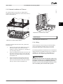
2.7.17 Cooling Tower Fan
2.7.18 The VLT Solution
Cooling tower fans are used to cool condenser water in
water-cooled chiller systems. Water-cooled chillers provide
the most efficient means of creating chilled water. They
are as much as 20% more efficient than air cooled chillers.
Depending on climate, cooling towers are often the most
energy efficient method of cooling the condenser water
from chillers.
Cooling towers cool the condenser water by evaporation.
The condenser water is sprayed into the cooling tower
onto the fill to increase its surface area. The tower fan
blows air through the fill and sprayed water to aid in the
evaporation. Evaporation removes energy from the water,
dropping its temperature. The cooled water collects in the
basin of the cooling tower where it is pumped back into
the chiller condenser and the cycle is repeated.
With a frequency converter, the cooling tower fans can be
controlled to the required speed to maintain the
condenser water temperature. The frequency converters
can also be used to turn the fan on and off as needed.
With the Danfoss HVAC frequency converter, as the cooling
tower fans drop below a certain speed, the cooling effect
decreases. When using a gear-box to frequency control the
tower fan, a minimum speed of 40–50% could be required.
The customer programmable minimum frequency setting
is available to maintain this minimum frequency even as
the feedback or speed reference calls for lower speeds.
130BB453.10
The frequency converter can be programmed to enter a
“sleep” mode and stop the fan until a higher speed is
required. Additionally, some cooling tower fans have
undesirable frequencies that can cause vibrations. These
frequencies can easily be avoided by programming the
bypass frequency ranges in the frequency converter.
Frequency
converter
Water Inlet
Temperature
Sensor
BASIN
Water Outlet
Conderser
Water pump
CHILLER
2 2
Introduction
Supply
Illustration 2.13 Frequency Converters Used with a Cooling Tower Fan
26
MG16C102 - Rev. 2013-08-20
Introduction
VLT® HVAC Drive FC 102 Design Guide
2.7.19 Condenser Pumps
2.7.20 The VLT Solution
Condenser water pumps are primarily used to circulate
water through the condenser section of water-cooled
chillers and their associated cooling tower. The condenser
water absorbs the heat from the condenser section and
releases it into the atmosphere in the cooling tower. These
systems provide the most efficient means of creating
chilled water. They are as much as 20% more efficient than
air cooled chillers.
Frequency converters can be added to condenser water
pumps instead of balancing the pumps with a throttling
valve or trimming the pump impeller.
2 2
130BB452.10
Using a frequency converter instead of a throttling valve
saves the energy that the valve would otherwise have
absorbed. This change can amount to savings of 15–20%
or more. Trimming the pump impeller is irreversible, so if
the conditions change and higher flow is required the
impeller must be replaced.
Frequency
converter
Water
Inlet
Flow or pressure sensor
BASIN
CHILLER
Water
Outlet
Condenser
Water pump
Throttling
valve
Supply
Illustration 2.14 Frequency Converter used with a Condenser Pump
MG16C102 - Rev. 2013-08-20
27
VLT® HVAC Drive FC 102 Design Guide
Primary pumps in a primary/secondary pumping system
can maintain a constant flow through devices that
encounter operation or control difficulties when exposed
to variable flow. The primary/secondary pumping
technique decouples the “primary” production loop from
the “secondary” distribution loop. Decoupling allows
devices such as chillers to obtain constant design flow and
operate properly while allowing the rest of the system to
vary in flow.
As the evaporator flow rate decreases in a chiller, the
chilled water begins to become over-chilled. As this
happens, the chiller attempts to decrease its cooling
capacity. If the flow rate drops far enough, or too quickly,
the chiller cannot shed its load sufficiently and the low
evaporator temperature safety trips the chiller, requiring a
manual reset. This situation is common in large installations, especially when two or more chillers in parallel are
installed if primary/secondary pumping is not used.
2.7.22 The VLT Solution
Depending on the size of the system and the size of the
primary loop, the energy consumption of the primary loop
can become substantial.
A frequency converter can be added to the primary
system, to replace the throttling valve and/or trimming of
the impellers, leading to reduced operating expenses. Two
control methods are common:
The first method uses a flow meter. Because the desired
flow rate is known and constant, a flow meter installed at
the discharge of each chiller can control the pump directly.
Using the PID controller, the frequency converter always
maintains the appropriate flow rate, even compensating
for the changing resistance in the primary piping loop as
chillers and their pumps are staged on and off.
The other method is local speed determination. The
operator simply decreases the output frequency until the
design flow rate is achieved.
Using a frequency converter to decrease the pump speed
is similar to trimming the pump impeller, but more
efficient. The balancing contractor simply decreases the
speed of the pump until the proper flow rate is achieved
and leaves the speed fixed. The pump operates at this
speed any time the chiller is staged on. Because the
primary loop lacks control valves or other devices that can
change the system curve, and the variance due to staging
pumps and chillers on and off is small, this fixed speed
remains appropriate. If the flow rate must be increased
later in the life of the system, the frequency converter can
simply increase the pump speed instead of requiring a
new pump impeller.
Flowmeter
Flowmeter
F
Frequency
converter
CHILLER
F
Frequency
converter
Illustration 2.15 Frequency Converters used with Primary Pumps in a Primary/Secondary Pump System
28
MG16C102 - Rev. 2013-08-20
130BB456.10
2.7.21 Primary Pumps
CHILLER
2 2
Introduction
Introduction
VLT® HVAC Drive FC 102 Design Guide
2.7.23 Secondary Pumps
2.7.24 The VLT Solution
Secondary pumps in a primary/secondary chilled water
pumping system are used to distribute the chilled water to
the loads from the primary production loop. The primary/
secondary pumping system is used to de-couple one
piping loop from another hydronically. In this case, the
primary pump maintains a constant flow through the
chillers, allowing the secondary pumps to vary flow,
increase control and save energy.
If the primary/secondary design concept is not used and a
variable volume system is designed, when the flow rate
drops far enough or too quickly, the chiller cannot shed its
load properly. The low evaporator temperature safety then
trips the chiller, requiring a manual reset. This situation is
common in large installations especially when two or more
chillers in parallel are installed.
While the primary/secondary system with 2-way valves
improves energy and system control, using frequency
converters increases the energy savings and control
potential further.
With the proper sensor location, the addition of frequency
converters allows the pumps to match their speed to the
system curve instead of the pump curve.
This eliminates wasted energy and most of the overpressurization, two-way valves can be subjected to.
As the monitored loads are reached, the 2-way valves close
down, increasing the differential pressure measured across
the load and two-way valve. As this differential pressure
starts to rise, the pump is slowed to maintain the control
head also called setpoint value. This setpoint value is
calculated by summing the pressure drop of the load and
two way valve together under design conditions.
NOTICE
P
Frequency
converter
130BB454.10
When running multiple pumps in parallel, they must run
at the same speed to increase energy savings, either
with individual dedicated frequency converters, or one
frequency converter running multiple pumps in parallel.
CHILLER
CHILLER
3
Frequency
converter
3
Illustration 2.16 Frequency Converters used with Secondary Pumps in a Primary/Secondary Pump System
MG16C102 - Rev. 2013-08-20
29
2 2
VLT® HVAC Drive FC 102 Design Guide
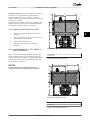
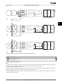
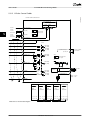
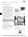
2.8 Control Structures
130BC514.11
2.8.1 Control Principle
3 Phase
power
input
91 (L1)
92 (L2)
93 (L3)
95 PE
DC bus
88 (-)
89 (+)
(U) 96
(V) 97
(W) 98
(PE) 99
Motor
(R+) 82
Brake
resistor
(R-) 81
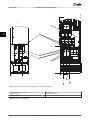
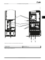
Illustration 2.17 Control Structure, 6-pulse
3 Phase
power
input
130BD462.10
2 2
Introduction
91-1 (L1-1)
92-1 (L2-1)
93-1 (L3-1)
95 PE
(U) 96
(V) 97
(W) 98
(PE) 99
Motor
Y
3 Phase
power
input
91-2 (L1-2)
92-2 (L2-2)
(R+) 82
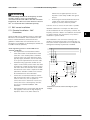
93-2 (L3-2)
95 PE
Brake
resistor
(R-) 81
Illustration 2.18 Control Structure, 12-pulse
The frequency converter is a high-performance unit for
demanding applications. It can handle various motor
control principles including:
•
•
•
30
U/f special motor mode
VVCplus
Short circuit behaviour on this frequency converter
depends on the 3 current transducers in the motor phases.
In H-40 Configuration Mode, it can be selected if using
open or closed loop.
Squirrel cage asynchronous motors
MG16C102 - Rev. 2013-08-20
Introduction
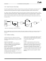
VLT® HVAC Drive FC 102 Design Guide
P 4-13
Motor speed
high limit [RPM]
Reference
handling
Remote
reference
P 4-14
Motor speed
high limit [Hz]
130BB153.10
2.8.2 Control Structure Open Loop
100%
P 3-4* Ramp 1
P 3-5* Ramp 2
0%
To motor
control
Remote
Auto mode
Hand mode
Linked to hand/auto
Reference
Ramp
Local
P 4-11
Motor speed
low limit [RPM]
Local
reference
scaled to
RPM or Hz
100%
-100%
LCP Hand on,
off and auto
on keys
P 3-13
Reference
site
P 4-12
Motor speed
low limit [Hz]
P 4-10
Motor speed
direction
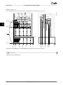
Illustration 2.19 Open Loop Structure
In the configuration shown in Illustration 2.19, H-40 Configuration Mode is set to [0] open loop. The resulting reference comes
from the reference handling system or the local reference and is fed through the ramp and speed limitations before
proceeding to the motor control.
The maximum frequency limit curbs output from the motor control.
2.8.3 PM/EC+ Motor Control
The Danfoss EC+ concept provides the possibility for using
high efficiency PM motors in IEC standard frame size
operated by Danfoss frequency converters.
The commissioning procedure is comparable to the
existing one for asynchronous (induction) motors by
utilising the Danfoss VVCplus PM control strategy.
Customer advantages:
• Option of motor technology (permanent magnet
or induction motor)
•
•
Installation and operation as on induction motors
•
Best system efficiency by choosing best
components
•
•
Possible retrofit of existing installations
Manufacturer independent when choosing system
components such as motors
High power range: 1.1 -1400 kW for induction
motors and 1.1–22 kW for PM motors
Current limitations:
• Currently only supported up to 22 kW
•
•
•
•
Currently limited to non-salient type PM motors
LC filters not supported with PM motors
Over voltage control algorithm is not supported
with PM motors
Kinetic backup algorithm is not supported with
PM motors
•
•
•
•
AMA algorithm is not supported with PM motors
No missing motor phase detection
No stall detection
No ETR function
2.8.4 Local (Hand On) and Remote (Auto
On) Control
The frequency converter can be operated manually via the
local control panel (LCP) or remotely via analog/digital
inputs or serial bus.
It is possible to start and stop the frequency converter by
LCP using the [Hand On] and [Off] keys, if allowed in the
following parameters:
•
•
•
•
K-40 [Hand] Button on Keypad
K-41 [Off] Button on Keypad
K-42 [Auto] Button on Keypad
K-43 [Reset] Button on Keypad
Alarms can be reset via the [Reset] key. After pressing
[Hand On], the frequency converter goes into Hand mode
and follows (as default) the local reference set by pressing
[▲] and [▼].
After pressing [Auto On] , the frequency converter goes
into Auto mode and follows (as default) the remote
reference. In this mode, it is possible to control the
frequency converter via the digital inputs and various serial
interfaces (RS-485, USB, or an optional fieldbus). See more
MG16C102 - Rev. 2013-08-20
31
2 2
VLT® HVAC Drive FC 102 Design Guide
about starting, stopping, changing ramps and parameter
set-ups in parameter group 5–1* Digital Inputs or
parameter group 8–5* Serial communication.
Hand
on
Off
Auto
on
Table 2.8 shows which conditions activate the local or
remote reference. One of them is always active, but both
cannot be active at the same time.
130BP046.10
2 2
Introduction
Reset
Local reference forces the configuration mode to open
loop, independent on the setting of H-40 Configuration
Mode.
Local reference is restored at power-down.
Illustration 2.20 LCP Keys
Hand Off
Auto
LCP Keys
Reference Site
F-02 Operation
Method
Active Reference
Hand
Linked to Hand/
Auto
Local
Hand -> Off
Linked to Hand/
Auto
Local
Auto
Linked to Hand/
Auto
Remote
Auto -> Off
Linked to Hand/
Auto
Remote
All keys
Local
Local
All keys
Remote
Remote
Table 2.8 Conditions for Local or Remote Reference
32
MG16C102 - Rev. 2013-08-20
Introduction
VLT® HVAC Drive FC 102 Design Guide
2.8.5 Control Structure Closed Loop
The internal controller allows the frequency converter to become a part of the controlled system. The frequency converter
receives a feedback signal from a sensor in the system. It compares this feedback to a setpoint reference value and
determines the error, if any, between these 2 signals. It then adjusts the speed of the motor to correct this error.
2 2
130BA359.12
For example, consider a pump application where the speed of a pump is controlled so that the static pressure in a pipe is
constant. The desired static pressure value is supplied to the frequency converter as the setpoint reference. A static pressure
sensor measures the actual static pressure in the pipe and supplies this value to the frequency converter as a feedback
signal. If the feedback signal is greater than the setpoint reference, the frequency converter slows down to reduce the
pressure. Likewise, if the pipe pressure is lower than the setpoint reference, the frequency converter speeds up to increase
the pump pressure.
100%
Ref.
Handling
(Illustration)
Feedback
Handling
(Illustration)
+
0%
Σ
_
Scale to
speed
PID
To motor
control
*[-1]
100%
-100%
P 20-81
PID Normal/Inverse
Control
P 4-10
Motor speed
direction
Illustration 2.21 Block Diagram of Closed Loop Controller
While the default values for the closed loop controller often provide satisfactory performance, the control of the system can
often be optimised by adjusting some of the closed loop controller parameters. It is also possible to auto tune the PI
constants.
2.8.6 Feedback Handling
Feedback handling can be configured to work with
applications requiring advanced control, such as multiple
setpoints and multiple feedbacks. Three types of control
are common.
Single Zone, Single Setpoint
Single zone single setpoint is a basic configuration.
Setpoint 1 is added to any other reference (if any, see
2.8.8 Reference Handling ) and the feedback signal is
selected using CL-20 Feedback Function.
Multi-Zone, Single Setpoint
Multi zone single setpoint uses 2 or 3 feedback sensors but
only 1 setpoint. The feedbacks can be added, subtracted
(only feedback 1 and 2) or averaged. In addition, the
maximum or minimum value could be used. Setpoint 1 is
used exclusively in this configuration.
frequency converter. [14] Multi Setpoint Maximum attempts
to keep all zones at or below their respective setpoints,
while [13] Multi Setpoint Min attempts to keep all zones at
or above their respective setpoints.
Example:
A 2 zone 2 setpoint application in which the Zone 1
setpoint is 15 bar and the feedback is 5.5 bar. Zone 2
setpoint is 4.4 bar and the feedback is 4.6 bar. If [14] Multi
Setpoint Max is selected, the setpoint and feedback of
Zone 2 are sent to the PID controller, since this has the
smaller difference (feedback is higher than setpoint,
resulting in a negative difference). If [13] Multi Setpoint Min
is selected, the setpoint and feedback of Zone 1 are sent
to the PID controller, since this has the larger difference
(feedback is lower than setpoint, resulting in a positive
difference).
If [13] Multi Setpoint Min is selected, the setpoint/feedback
pair with the largest difference controls the speed of the
MG16C102 - Rev. 2013-08-20
33
0%
Setpoint to
Reference
Handling
Setpoint 1
130BA354.12
VLT® HVAC Drive FC 102 Design Guide
P 20-21
Setpoint 2
0%
P 20-22
Multi setpoint min.
Multi setpoint max.
Setpoint 3
P 20-23
0%
Feedback
Feedback 1 Source
P 20-00
Feedback 2 Source
P 20-03
Feedback 3 Source
P 20-06
Feedback conv.
P 20-01
Feedback 1
Feedback conv.
P 20-04
Feedback 2
Feedback conv.
P 20-07
Feedback 3
Feedback 1 only
Feedback 2 only
Feedback 3 only
Sum (1+2+3)
Difference (1-2)
Average (1+2+3)
Minimum (1|2|3)
Maximum (1|2|3)
0%
Feedback Function
P 20-20
Illustration 2.22 Feedback Signal Processing
2.8.7 Feedback Conversion
In some applications it may be useful to convert the
feedback signal. One example of this is using a pressure
signal to provide flow feedback. Since the square root of
pressure is proportional to flow, the square root of the
pressure signal yields a value proportional to the flow. This
is shown in Illustration 2.23.
130BA358.11
2 2
Introduction
Ref.
signal
Ref.+
-
Desired
flow
PID
P 20-01
P 20-04
P 20-07
FB conversion
FB
P
Flow
Preset references.
•
•
The preset relative reference.
External references (analog inputs, pulse
frequency inputs, digital potentiometer inputs
and serial communication bus references).
Feedback controlled setpoint.
Up to 8 preset references can be programmed in the
frequency converter. The active preset reference can be
selected using digital inputs or the serial communications
bus. The reference can also be supplied externally, most
commonly from an analogue input. This external source is
selected by one of the 3 reference source parameters
(F-01 Frequency Setting 1, C-30 Frequency Command 2 and
C-34 Frequency Command 3).
Flow
P
FB
signal
•
•
Digipot is a digital potentiometer. This is also commonly
called a speed-up/speed-down control or a floating point
control. To set it up, program 1 digital input to increase
the reference while another digital input is programmed to
decrease the reference. A 3rd digital input can be used to
reset the digipot reference. All reference resources and the
bus reference are added to produce the total external
reference. The external reference, the preset reference or
the sum of the 2 can be selected to be the active
reference. Finally, this reference can by be scaled using
F-64 Preset Relative Reference.
P
Illustration 2.23 Feedback Conversion
2.8.8 Reference Handling
Details for Open Loop and Closed Loop operation.
The remote reference is comprised of:
34
MG16C102 - Rev. 2013-08-20
Introduction
VLT® HVAC Drive FC 102 Design Guide
The scaled reference is calculated as follows:
Reference = X + X ×
Y
( 100
)
Where X is the external reference, the preset reference or the sum of these and Y is F-64 Preset Relative Reference in [%].
2 2
130BA357.12
If Y, F-64 Preset Relative Reference is set to 0%, the reference will not be affected by the scaling.
P 3-14
Preset relative ref.
Input command:
Preset ref. bit0, bit1, bit2
P 1-00
Configuration mode
[0]
[1]
[2]
P 3-10
Preset ref.
[3]
Input command:
Freeze ref.
[4]
Open loop
Scale to
RPM,Hz
or %
[5]
[6]
P 3-04
Ref. function
[7]
Y
X
Σ
Relative
X+X*Y
/100
max ref.
%
Remote
ref.
Σ
±200%
±200%
%
min ref.
No function
on
P 3-15
Ref. 1 source
Analog inputs
±200%
off
Frequency inputs
Ext. closed loop outputs
±100%
Freeze ref.
&
increase/
decrease
ref.
Input command:
Ref. Preset
DigiPot
Scale to
Closed
loop
unit
Closed loop
Input command:
Speed up/ speed down
No function
P 3-16
Ref. 2 source
Analog inputs
Frequency inputs
Ref. in %
Σ
Ext. closed loop outputs
DigiPot
External
reference
in %
P 1-00
Configuration mode
No function
P 3-17
Ref. 3 source
Analog inputs
Closed loop
±200%
Frequency inputs
Setpoint
Ext. closed loop outputs
From Feedback Handling
DigiPot
0%
Open loop
Increase
0/1
Decrease
0/1
DigiPot
Digipot ref.
±200%
Clear
0/1
Bus
reference
Illustration 2.24 Remote Reference
MG16C102 - Rev. 2013-08-20
35
2.8.9 Example of Closed Loop PID Control
Cold air
100kW
Heat
generating
process
W n °C
Temperature
transmitter
Fan speed
Temperature
In a ventilation system, maintain the temperature at a
constant value. The desired temperature is set between -5
and +35 °C using a 0-10 V potentiometer. Because this is a
cooling application, if the temperature is above the setpoint value, increase the speed of the fan to provide more
cooling air flow. The temperature sensor has a range of -10
to +40 °C and uses a 2-wire transmitter to provide a 4-20
mA signal. The output frequency range of the frequency
converter is 10 to 50 Hz.
130BA218.10
VLT® HVAC Drive FC 102 Design Guide
Heat
2 2
Introduction
Illustration 2.25 Closed Loop Control for a Ventilation System
1.
Start/Stop via the switch connected between
terminals 12 (+24 V) and 18.
2.
Temperature reference via a potentiometer (-5–
+35 °C, 0–10 V) connected to the following
terminals:
•
•
•
3.
36
50 (+10 V)
53 (input)
55 (common)
Temperature feedback via transmitter (-10–40 °C,
4–20 mA) connected to terminal 54. Switch S202
behind the LCP set to ON (current input).
MG16C102 - Rev. 2013-08-20
Introduction
VLT® HVAC Drive FC 102 Design Guide
2.8.10 Programming Order
NOTICE
2 2
This example assumes an induction motor is used, so P-20 Motor Construction = [0] Asynchron.
Function
Parameter no.
Setting
Set the motor parameters using nameplate data.
1-2*
As specified by motor name plate
Run Automatic Motor Adaptation (AMA).
1-29
[1] Enable complete AMAand then run the AMA
function.
1-28
If the motor runs in the wrong direction, remove
power temporarily and reverse two of the motor
phases.
1) Make sure the motor runs properly. Do the following:
2) Check that the motor is running in the right direction.
Run motor rotation check.
3) Make sure the frequency converter limits are set to safe values
Check that the ramp settings are within capabilities of
the frequency converter and allowed application
operating specifications.
3-41
3-42
60 s
60 s
Depends on motor/load size!
Also active in Hand mode.
Prohibit the motor from reversing (if necessary)
4-10
[0] Clockwise
Set acceptable limits for the motor speed.
4-12
4-14
4-19
10 Hz, Motor min speed
1-00
[3] Closed Loop
20-12
[71] Bar
20-13
20-14
0 Bar
10 Bar
Switch from open loop to closed loop.
50 Hz, Motor max speed
50 Hz, Drive max output frequency
4) Configure the feedback to the PID controller.
Select the appropriate reference/feedback unit.
5) Configure the set-point reference for the PID controller.
Set acceptable limits for the set-point reference.
Choose current or voltage by switches S201 / S202
6) Scale the analogue inputs used for set-point reference and feedback.
Scale analogue Input 53 for the pressure range of the
potentiometer (0–10 Bar, 0–10 V).
6-10
6-11
6-14
6-15
0V
10 V (default)
0 Bar
10 Bar
Scale analogue input 54 for pressure sensor (0–10 Bar,
4–20 mA)
6-22
6-23
6-24
6-25
4 mA
20 mA (default)
0 Bar
10 Bar
20-93
20-94
See Optimization of the PID Controller, below.
0-50
[1] All to LCP
7) Tune the PID controller parameters.
Adjust the closed loop controller, if needed.
8) Finished
Save the parameter setting to the LCP
Table 2.9 Programming Order
MG16C102 - Rev. 2013-08-20
37
2 2
Introduction
VLT® HVAC Drive FC 102 Design Guide
2.8.11 Tuning the Closed Loop Controller
Once the closed loop controller has been set up, the
performance of the controller should be tested. In many
cases, its performance may be acceptable using the default
values of CL-93 PID Proportional Gain and CL-94 PID Integral
Time. However, in some cases it may be helpful to
optimize these parameter values to provide faster system
response while still controlling speed overshoot.
2.8.12 Manual PID Adjustment
38
1.
Start the motor.
2.
Set CL-93 PID Proportional Gain to 0.3 and
increase it until the feedback signal begins to
oscillate. If necessary, start and stop the
frequency converter or make step changes in the
set-point reference to attempt to cause
oscillation.
3.
Reduce the PID proportional gain until the
feedback signal stabilizes. Reduce the proportional gain by 40-60%.
4.
Set CL-94 PID Integral Time to 20 sec. and reduce
it until the feedback signal begins to oscillate. If
necessary, start and stop the frequency converter
or make step changes in the set-point reference
to attempt to cause oscillation.
5.
Increase the PID integral time until the feedback
signal stabilizes. Increase of the integral time by
15-50%.
6.
CL-95 PID Differentiation Time should only be used
for fast-acting systems. The typical value is 25%
of CL-94 PID Integral Time. The differential
function should only be used when the setting of
the proportional gain and the integral time has
been fully optimized. Make sure that oscillations
of the feedback signal are sufficiently dampened
by the low-pass filter for the feedback signal
(parameters 6-16, 6-26, 5-54 or 5-59 as required).
MG16C102 - Rev. 2013-08-20
Introduction
VLT® HVAC Drive FC 102 Design Guide
2.9 General aspects of EMC
2.9.1 General Aspects of EMC Emissions
2 2
Electrical interference is usually conducted at frequencies in the range 150 kHz to 30 MHz. Airborne interference from the
frequency converter system in the range 30 MHz to 1 GHz is generated from the inverter, motor cable, and motor.
Capacitive currents in the motor cable coupled with a high dU/dt from the motor voltage generate leakage currents.
The use of a screened motor cable increases the leakage current (see Illustration 2.26) because screened cables have higher
capacitance to earth than unscreened cables. If the leakage current is not filtered, causing greater interference on the mains
in the radio frequency range below approximately 5 MHz. Since the leakage current (I1) is carried back to the unit through
the screen (I 3), there is only a small electromagnetic field (I4) from the screened motor cable.
CS
z
L1
z
L2
V
z
L3
W
z PE
PE
CS
U
I1
I2
CS
I3
1
2
CS
CS
I4
3
175ZA062.12
The screen reduces the radiated interference but increases the low-frequency interference on the mains. The motor cable
screen must be connected to the frequency converter enclosure as well as the motor enclosure. This is best done by using
integrated screen clamps so as to avoid twisted screen ends (pigtails). These increase the screen impedance at higher
frequencies, which reduces the screen effect and increases the leakage current (I4).
If a screened cable is used for fieldbus, relay, control cable, signal interface and brake, the screen must be mounted on the
enclosure at both ends. In some situations, however, it will be necessary to break the screen to avoid current loops.
CS
I4
5
4
6
Illustration 2.26 Leakage Currents
1
Earth wire
2
Screen
3
AC mains supply
4
Frequency converter
5
Screened motor cable
6
Motor
Table 2.10 Legend to Illustration 2.26
If the screen is to be placed on a mounting plate for the frequency converter, the mounting plate must be made of metal,
because the screen currents have to be conveyed back to the unit. Moreover, ensure good electrical contact from the
mounting plate through the mounting screws to the frequency converter chassis.
Use of unscreened cables does not comply with all emission requirements, although the immunity requirements are
observed.
To reduce the interference level from the entire system (unit + installation), make motor and brake cables as short as
possible. Avoid placing cables with a sensitive signal level alongside motor and brake cables. Radio interference higher than
50 MHz (airborne) is generated by the control electronics. See 5.7 EMC-correct Installation for more information on EMC.
MG16C102 - Rev. 2013-08-20
39
2 2
Introduction
VLT® HVAC Drive FC 102 Design Guide
2.9.2 Emission Requirements
According to the EMC product standard for adjustable speed frequency converters EN/IEC 61800-3:2004 the EMC
requirements depend on the intended use of the frequency converter. Four categories are defined in the EMC product
standard. The definitions of the 4 categories and the requirements for mains supply voltage conducted emissions are given
in Table 2.11.
Conducted emission requirement
according to the limits given in EN
55011
Category
Definition
C1
Frequency converters installed in the first environment (home and office) with a
supply voltage less than 1000 V.
Class B
C2
Frequency converters installed in the first environment (home and office) with a
supply voltage less than 1000 V, which are neither plug-in nor movable and are
intended to be installed and commissioned by a professional.
Class A Group 1
C3
Frequency converters installed in the second environment (industrial) with a supply
voltage lower than 1000 V.
Class A Group 2
C4
Frequency converters installed in the second environment with a supply voltage
equal to or above 1000 V or rated current equal to or above 400 A or intended for
use in complex systems.
No limit line.
An EMC plan should be made.
Table 2.11 Emission Requirements
When using generic emission standards, the frequency converters must comply with the limits in Table 2.12.
Conducted emission requirement
according to the limits given in EN
55011
Environment
Generic standard
First environment
(home and office)
EN/IEC 61000-6-3 Emission standard for residential, commercial
and light industrial environments.
Class B
Second environment
(industrial environment)
EN/IEC 61000-6-4 Emission standard for industrial environments.
Class A Group 1
Table 2.12 Emission Requirements, Generic Standards
40
MG16C102 - Rev. 2013-08-20
Introduction
VLT® HVAC Drive FC 102 Design Guide
2.9.3 EMC Test Results (Emission)
The test results in Table 2.13 have been obtained using a system with a frequency converter (with options if relevant), a
screened control cable, a control box with potentiometer, as well as a motor and motor screened cable.
RFI filter type
Phase
type
Conducted emission
Maximum shielded cable length
Industrial environment
Setup:
S/T
Radiated emission
Housing, trades
and light
industries
Industrial
environment
Housing, trades, and
light industries
EN 55011 Class
A1
EN 55011 Class B
EN 55011
Class A2
EN 55011
Class A1
EN 55011 Class
B
meter
meter
meter
110-1000 kW 380-480 V
T4
50
No
No
No
No
45-1200 kW 525-690 V
T7
150
No
No
No
No
110-1000 kW 380-480 V
T4
150
150
No
Yes
No
110-400 kW 525-690 V
T7
150
30
No
No
No
250-800 kW 380-480 V
T4
150
No
No
No
No
355-1200 kW 525-690 V
T7
150
No
No
No
No
250-800 kW 380-480 V
T4
150
150
No
Yes
No
355-1200 kW 525-690 V
T7
150
25
No
No
No
H2 (6-pulse)
2 2
H4 (6-pulse)
B2 (12-pulse)
B4 (12-pulse)
Table 2.13 EMC Test Results (Emission)
WARNING
In a domestic environment, this product has the potential to cause radio interference, in which case supplementary
mitigation measures are required. This type of power drive system is not intended to be used on a low-voltage public
network which supplies domestic premises. Radio frequency interference is expected when used on such a network.
MG16C102 - Rev. 2013-08-20
41
VLT® HVAC Drive FC 102 Design Guide
2.9.4 General Aspects of Harmonics
Emission
2.9.5 Harmonics Emission Requirements
A frequency converter takes up a non-sinusoidal current
from mains, which increases the input current IRMS. A nonsinusoidal current is transformed by means of a Fourier
analysis and split up into sine-wave currents with different
frequencies with 50 Hz as the basic frequency:
Harmonic currents
I1
I5
I7
Hz
50
250
350
Options:
Definition:
1
IEC/EN 61000-3-2 Class A for 3-phase balanced
equipment (for professional equipment only up to 1
kW total power).
2
IEC/EN 61000-3-12 Equipment 16 A-75 A and professional equipment as from 1 kW up to 16 A phase
current.
Table 2.15 Equipment Connected to the Public Supply Network
2.9.6 Harmonics Test Results (Emission)
Table 2.14 Harmonic Currents
The harmonics do not affect the power consumption
directly but increase the heat losses in the installation
(transformer, cables). Consequently, in plants with a high
percentage of rectifier load, maintain harmonic currents at
a low level to avoid overload of the transformer and high
temperature in the cables.
Power sizes up to PK75 in T2 and T4 complies with IEC/EN
61000-3-2 Class A. Power sizes from P1K1 and up to P18K
in T2 and up to P90K in T4 complies with IEC/EN
61000-3-12, Table 4. Power sizes P110 - P450 in T4 also
complies with IEC/EN 61000-3-12 even though not
required because currents are above 75 A.
175HA034.10
2 2
Introduction
Illustration 2.27 Harmonics Diagram
Individual Harmonic Current In/I1 (%)
I5
I7
I11
I13
Actual
(typical)
40
20
10
8
Limit for
Rsce≥120
40
25
15
10
Harmonic current distortion factor (%)
NOTICE
Some of the harmonic currents might disturb communication equipment connected to the same transformer or
cause resonance in connection with power-factor
correction batteries.
THD
PWHD
Actual
(typical)
46
45
Limit for
Rsce≥120
48
46
Table 2.16 Harmonics Test Results (Emission)
To ensure low harmonic currents, the frequency converter
is equipped with intermediate circuit coils as standard. This
normally reduces the input current IRMS by 40%.
The voltage distortion on the mains supply voltage
depends on the size of the harmonic currents multiplied
by the mains impedance for the frequency in question.
The total voltage distortion THD is calculated on the basis
of the individual voltage harmonics using this formula:
THD % = U
2
2
2
+ U
+ ... + U
5
7
N
(UN% of U)
Provided that the short-circuit power of the supply Ssc is
greater than or equal to:
SSC = 3 × RSCE × Umains × Iequ =
3 × 120 × 400 × Iequ
at the interface point between the user’s supply and the
public system (Rsce).
It is the responsibility of the installer or user of the
equipment to ensure, by consultation with the distribution
network operator if necessary, that the equipment is
connected only to a supply with a short-circuit power Ssc
greater than or equal to that specified in the equation.
Other power sizes can be connected to the public supply
network by consultation with the distribution network
operator.
Compliance with various system level guidelines:
The harmonic current data in the table are given in
accordance with IEC/EN61000-3-12 with reference to the
power drive systems product standard. They may be used
42
MG16C102 - Rev. 2013-08-20
Introduction
VLT® HVAC Drive FC 102 Design Guide
as the basis for calculation of the influence harmonic
currents have on the power supply system and for the
documentation of compliance with relevant regional
guidelines: IEEE 519 -1992; G5/4.
•
EN 61000-4-2 (IEC 61000-4-2): Electrostatic
discharges (ESD): Simulation of electrostatic
discharges from human beings.
•
EN 61000-4-3 (IEC 61000-4-3): Incoming electromagnetic field radiation, amplitude modulated
simulation of the effects of radar and radio
communication equipment as well as mobile
communications equipment.
•
EN 61000-4-4 (IEC 61000-4-4): Burst transients:
Simulation of interference brought about by
switching a contactor, relay or similar devices.
•
EN 61000-4-5 (IEC 61000-4-5): Surge transients:
Simulation of transients brought about, by
lightning that strikes near installations, for
example.
•
EN 61000-4-6 (IEC 61000-4-6): RF Common
mode: Simulation of the effect from radiotransmission equipment joined by connection
cables.
2.9.7 Immunity Requirements
The immunity requirements for frequency converters
depend on the environment in which they are installed.
The requirements for the industrial environment are higher
than the requirements for the home and office
environments. All Danfoss frequency converters comply
with the requirements for the industrial environment and
consequently comply with the lower requirements for
home and office environment with a large safety margin.
To document immunity against electrical interference from
electrical phenomena, the following immunity tests have
been performed on a system consisting of a frequency
converter (with options if relevant), a screened control
cable and a control box with potentiometer, motor cable
and motor.
The tests were performed in accordance with the following
basic standards:
See Table 2.17.
Voltage range: 380-480 V, 525-600 V, 525-690 V
Basic standard
Burst
IEC 61000-4-4
Acceptance criteria
Line
Surge
IEC 61000-4-5
ESD
IEC
61000-4-2
Radiated electromagnetic
field
IEC 61000-4-3
RF common
mode voltage
IEC 61000-4-6
B
B
B
A
A
4 kV CM
2 kV/2Ω DM
4 kV/12Ω CM
—
—
10 VRMS
Motor
4 kV CM
Brake
4 kV CM
1)
—
—
10 VRMS
kV/2Ω1)
—
—
10 VRMS
1)
4 kV/2Ω
4
Load sharing
4 kV CM
4 kV/2Ω
—
—
10 VRMS
Control wires
2 kV CM
2 kV/2Ω1)
—
—
10 VRMS
Standard bus
2 kV CM
2 kV/2Ω1)
—
—
10 VRMS
Relay wires
2 kV CM
2 kV/2Ω
1)
—
—
10 VRMS
Application and Fieldbus
options
2 kV CM
2 kV/2Ω
1)
—
—
10 VRMS
LCP cable
2 kV CM
2 kV/2Ω
1)
—
—
10 VRMS
—
—
10 VRMS
10 V/m
—
External 24 V DC
Enclosure
2 V CM
—
0.5 kV/2Ω
DM2)
1 kV/12Ω CM3)
—
8 kV AD4)
6 kV CD5)
Table 2.17 EMC Immunity Form
1)
2)
3)
4)
5)
Injection on cable shield
AD-Air discharge
CD-Contact discharge
CM-Common mode
DM-Differential mode
MG16C102 - Rev. 2013-08-20
43
2 2
VLT® HVAC Drive FC 102 Design Guide
The functional galvanic isolation is for the 24 V back-up
option and for the standard bus interface.
2.10 Galvanic Isolation (PELV)
2.10.1 PELV - Protective Extra Low Voltage
WARNING
PELV (Protective Extra Low Voltage) offers protection
through extra low voltage. To ensure protection against
electric shock, use a PELV electrical supply and install as
described in local/national regulations on PELV supplies.
All control terminals and relay terminals 01-03/04-06
comply with PELV (Protective Extra Low Voltage). (Does not
apply to grounded Delta leg above 400 V.)
Galvanic (ensured) isolation is obtained by fulfilling
requirements for higher isolation and providing the
relevant creepage/clearance distances. These requirements
are described in the EN 61800-5-1 standard.
The components that make up the electrical isolation, as
described below, also comply with the requirements for
higher isolation and the relevant test as described in EN
61800-5-1.
The PELV galvanic isolation is shown in six locations. See
Illustration 2.28:
M
6
5
4
1
2
a
b
WARNING
Touching the electrical parts could be fatal, even after
the equipment has been disconnected from mains.
Ensure that other voltage inputs, such as load sharing
(linkage of DC intermediate circuit), as well as the motor
connection for kinetic back-up, have been disocnnect.
Before touching any electrical parts, wait at least the
amount of time indicated in Table 2.1. Shorter time is
allowed only if indicated on the nameplate for the
specific unit.
Follow national and local codes regarding protective
earthing of equipment with a leakage current > 3,5 mA.
Frequency converter technology implies high frequency
switching at high power. This will generate a leakage
current in the earth connection. A fault current in the
frequency converter at the output power terminals might
contain a DC component, which can charge the filter
capacitors and cause a transient earth current.
The earth leakage current is made up of several contributions and depends on various system configurations
including RFI filtering, screened motor cables, and
frequency converter power.
Illustration 2.28 Galvanic Isolation
130BB955.11
3
Installation at high altitude:
380–480 V, enclosure A, B and C: At altitudes above 2
km, contact Danfoss regarding PELV.
380–480 V, enclosure D, E and F: At altitudes above 3
km, contact Danfoss regarding PELV.
525–690 V: At altitudes above 2 km, please contact
Danfoss regarding PELV.
2.11 Earth Leakage Current
To maintain PELV, all connections made to the control
terminals must be PELV.
130BA056.10
2 2
Introduction
Leakage current [mA]
a
1
Power supply (SMPS) including signal isolation of UDC,
indicating the intermediate current voltage
2
Gate drive that runs the IGBTs (trigger transformers/optocouplers)
3
Current transducers
4
Opto-coupler, brake module
5
Internal inrush, RFI, and temperature measurement circuits
6
Custom relays
a
Functional Galvanic Isolation
b
Functional Galvanic Isolation
b
Cable length [m]
Illustration 2.29 Cable Length and Power Size Influence on
Leakage Current. Pa > Pb.
Table 2.18 Legend to Illustration 2.28
44
MG16C102 - Rev. 2013-08-20
Leakage current [mA]
130BB957.11
VLT® HVAC Drive FC 102 Design Guide
130BB956.11
Introduction
Leakage current [mA]
2 2
100 Hz
THVD=0%
2 kHz
THVD=5%
100 kHz
Illustration 2.30 Line Distortion Influences Leakage Current.
Illustration 2.32 Effect of the RCD frequency
NOTICE
See the RCD Application Note for more information.
When a filter is used, turn off SP-50 RFI Filter when
charging the filter, to avoid a high leakage current
making the RCD switch.
2.12 Brake Function
EN/IEC61800-5-1 (Power Drive System Product Standard)
requires special care if the leakage current exceeds 3.5 mA.
Earth grounding must be reinforced in one of the
following ways:
In certain applications (in a tunnel or underground railway
station ventilation system, for example), it is desirable to
bring the motor to a stop faster than can be achieved
through controlling via ramp down or by free-wheeling. In
such applications, use dynamic braking with a brake
resistor to ensure that the energy is absorbed in the
resistor and not in the frequency converter.
•
Earth ground wire (terminal 95) of at least 10
mm2
•
2 separate earth ground wires both complying
with the dimensioning rules
See EN/IEC61800-5-1 and EN50178 for further information.
Using RCDs
Where residual current devices (RCDs), also known as earth
leakage circuit breakers (ELCBs), are used, comply with the
following:
• Use only RCDs of type B, which are capable of
detecting AC and DC currents
•
Use RCDs with an inrush delay to prevent faults
due to transient earth currents
Dimension RCDs according to the system configuration and environmental considerations
130BB958.11
•
RCD with low f cut-off
L leakage [mA]
RCD with high f cut-off
50 Hz
Mains
150 Hz
3rd harmonics
f sw
2.12.1 Brake Resistor Selection
If the amount of kinetic energy transferred to the resistor
in each braking period is not known, calculate the average
power on the basis of the cycle time and braking time
(intermittent duty cycle). The resistor intermittent duty
cycle is an indication of the duty cycle at which the
resistor is active. Illustration 2.33 shows a typical braking
cycle.
The intermittent duty cycle for the resistor is calculated as
follows:
Duty Cycle = tb / T
T = cycle time in seconds
tb is the braking time in seconds (as part of the total cycle
time)
f [Hz]
Cable
fs
Illustration 2.31 Mains Contributions to Leakage Current.
MG16C102 - Rev. 2013-08-20
45
VLT® HVAC Drive FC 102 Design Guide
130BA167.10
Introduction
Load
2 2
For 480 V and 600 V frequency converters, Rrec at 160%
braking torque is written as:
690V : Rrec =
832664
Pmotor
Ω
NOTICE
Speed
For resistor selection information, refer to
the Brake Resistor Design Guide
ta
tc
tb
to
ta
tc
tb
to
ta
NOTICE
T
Time
Illustration 2.33 Typical Braking Cycle
Danfoss offers brake resistors with duty cycle of 10% and
40% suitable for use with the VLT® HVAC Drive frequency
converter series. If a 10% duty cycle resistor is applied, this
is capable of absorbing braking power up to 10% of the
cycle time with the remaining 90% being used to dissipate
heat from the resistor.
2.12.2 Brake Resistor Calculation
2
Udc
Rbr Ω =
Ppeak
Size
Brake active
Warning
before cut
out
Cut out (trip)
3 x 380-480 V
778 V
810 V
820 V
3 x 525-690 V
1084 V
1109 V
1130 V
Table 2.19 Effect of Brake Function on Mains Power Supply
NOTICE
Check that the brake resistor can cope with a voltage of
820 V or 1130 V - unless Danfoss brake resistors are
used.
Danfoss recommends the brake resistance Rrec, which
guarantees that the frequency converter is able to brake at
the highest braking torque (Mbr(%)) of 110%. The formula
can be written as:
46
If a short circuit in the brake transistor occurs, power
dissipation in the brake resistor is only prevented by
using a mains switch or contactor to disconnect the
mains for the frequency converter. (The contactor can be
controlled by the frequency converter).
Do not touch the brake resistor as it can get
very hot during braking.
The brake resistance depends on the intermediate circuit
voltage (UDC).
The brake function of the frequency converter is settled in
3 areas of mains power supply:
ηmotor is typically at 0.90
η is typically at 0.98
NOTICE
WARNING
Ppeak = Pmotor x Mbr x ηmotor x η[W]
2 x 100
Udc
Rrec Ω =
Pmotor x Mbr (%) x x
motor
The resistor brake circuit resistance selected should not
be higher than that recommended by Danfoss. If a brake
resistor with a higher ohmic value is selected, the
braking torque may not be achieved because there is a
risk that the frequency converter cuts out for safety
reasons.
2.12.3 Control with Brake Function
The brake is protected against short-circuiting of the brake
resistor, and the brake transistor is monitored to ensure
that short-circuiting of the transistor is detected. A relay/
digital output can be used for protecting the brake resistor
against overloading in connection with a fault in the
frequency converter.
In addition, the brake makes it possible to read out the
momentary power and the mean power for the latest 120
seconds. The brake can also monitor the power energizing
and make sure it does not exceed a limit selected in
B-12 Brake Power Limit (kW). In B-13 Braking Thermal
Overload, select the function to carry out when the power
transmitted to the brake resistor exceeds the limit set in
B-12 Brake Power Limit (kW).
NOTICE
Monitoring the brake power is not a safety function. A
thermal switch is required. The brake resistor circuit is
not earth leakage protected.
Over voltage control (OVC), for units without a brake
resistor, can be selected as an alternative brake function in
B-17 Over-voltage Control. This function is active for all
units. The function ensures that a trip can be avoided if
MG16C102 - Rev. 2013-08-20
Introduction
VLT® HVAC Drive FC 102 Design Guide
the DC link voltage increases. This is done by increasing
the output frequency to limit the voltage from the DC link.
the value of 1-40 Back EMF at 1000 RPM, P-06 Base
Speed and P-39 Motor Poles.
If it is possible that the motor may overspeed, a
brake resistor is recommended.
NOTICE
OVC cannot be activated when running a PM motor
(when P-20 Motor Construction is set to [1] PM non
salient SPM).
2.12.4 Brake Resistor Cabling
EMC (twisted cables/shielding)
Twist the wires to reduces noise between the brake
resistor and the frequency converter.
Use a metal screen for enhanced EMC performance
2.13 Extreme Running Conditions
Short Circuit (Motor Phase – Phase)
The frequency converter is protected against short circuits
by current measurement in each of the three motor phases
or in the DC link. A short circuit between 2 output phases
causes an overcurrent in the inverter. The inverter is
turned off individually when the short circuit current
exceeds the permitted value (Alarm 16 Trip Lock).
See certificate in 2.6.3 Approvals & Certificates.
Output Switching
Output switching between the motor and the frequency
converter is permitted. Output switching does not damage
the frequency converter in any way but may cause fault
messages.
Motor-generated Over-voltage
The voltage in the intermediate circuit is increased when
the motor acts as a generator. This occurs in following
cases:
•
The load drives the motor (at constant output
frequency from the frequency converter),
generating energy.
•
During deceleration ("ramp-down") if the moment
of inertia is high, the friction is low and the rampdown time is too short for the energy to be
dissipated as a loss in the frequency converter,
the motor and the installation.
•
Incorrect slip compensation setting may cause
higher DC link voltage.
•
Back-EMF (electromotive force) from PM motor
operation. If coasted at high rpm, the PM motor
back-EMF may potentially exceed the maximum
voltage tolerance of the frequency converter and
cause damage. To help prevent this, the value of
F-03 Max Output Frequency 1 is automatically
limited based on an internal calculation based on
WARNING
The frequency converter must be equipped
with a break chopper.
The control unit may attempt to correct the ramp if
possible (B-17 Over-voltage Control).
The inverter turns off to protect the transistors and the
intermediate circuit capacitors when a certain voltage level
is reached.
See parameters B-10 Brake Function and B-17 Over-voltage
Control to select the method used for controlling the
intermediate circuit voltage level.
NOTICE
OVC can not be activated when running a PM motor
(when P-20 Motor Construction is set to [1] PM non salient
SPM.
Mains Drop-out
During a mains drop-out, the frequency converter keeps
running until the intermediate circuit voltage drops below
the minimum stop level, which is typically 15% below the
lowest rated supply voltage. The mains voltage before the
drop-out and the motor load determine how long it takes
for the inverter to coast.
Static Overload in VVCplus mode
When the frequency converter is over loaded (the torque
limit in F-40 Torque Limiter (Driving)/F-41 Torque Limiter
(Braking) is reached), the controls reduce the output
frequency to reduce the load.
If the overload is excessive, a current may occur that
makes the frequency converter cut out after approx. 5-10
s.
Operation within the torque limit is limited in time (0-60 s.)
in SP-25 Trip Delay at Torque Limit.
2.13.1 Motor Thermal Protection
Motor thermal protection prevents the motor from
overheating. It is an electronic feature that simulates a
bimetal relay based on internal measurements. The characteristic is shown in Illustration 2.34
In Illustration 2.34, the X-axis is showing the ratio between
Imotor and Imotor nominal. The Y-axis is showing the time in
seconds before the ETR cuts off and trips the frequency
converter. The curves are showing the characteristic
MG16C102 - Rev. 2013-08-20
47
2 2
VLT® HVAC Drive FC 102 Design Guide
A
B
+24V
2000
1000
600
500
400
300
200
130BA151.11
t [s]
Example: Using a digital input and 24 V as power supply:
The frequency converter trips when the motor temperature
is too high.
Parameter set-up:
Set F-10 Electronic Overload to Thermistor Trip [2]
Set F-12 Motor Thermistor Input to Digital Input 33 [6]
OFF
12 13 18 19 27 29 32 33 20 37
fOUT = 1 x f M,N(par. 1-23)
100
60
50
40
30
20
10
fOUT = 2 x f M,N
fOUT = 0.2 x f M,N
ON
PTC / Thermistor
<6.6 k Ω >10.8 k Ω
R
Illustration 2.36 Digital Input and 24 V Power Supply
IM
IMN(par. 1-24)
Illustration 2.34 Nominal Speed
It is clear that at lower speed the ETR cuts off at lower
heat due to less cooling of the motor. In that way, the
motor is protected from overheating even at low speed.
The ETR feature is calculating the motor temperature
based on actual current and speed. The calculated
temperature is visible as a readout parameter in
DR-18 Motor Thermal in the frequency converter.
Example: Using a digital input and 10 V as power supply:
The frequency converter trips when the motor temperature
is too high.
Parameter set-up:
Set F-10 Electronic Overload to Thermistor Trip [2]
Set F-12 Motor Thermistor Input to Digital Input 33 [6]
130BA152.10
1.0 1.2 1.4 1.6 1.8 2.0
+10V
2 2
175ZA052.12
nominal speed at twice the nominal speed and at 0.2x the
nominal speed.
GND
Introduction
39 42 50 53 54 55
OFF
The thermistor cut-out value is > 3 kΩ.
12 13 18 19 27 29 32 33 20 37
Integrate a thermistor (PTC sensor) in the motor for
winding protection.
ON
175HA183.10
Motor protection can be implemented using a range of
techniques: PTC sensor in motor windings; mechanical
thermal switch (Klixon type); or Electronic Thermal Relay
(ETR).
R
(Ω)
4000
3000
1330
PTC / Thermistor
ϑ [°C]
ϑ nominel +5°C
Illustration 2.35 Trip
48
R
Example: Using an analog input and 10 V as power
supply:
The frequency converter trips when the motor temperature
is too high.
Parameter set-up:
Set F-10 Electronic Overload to [2] Thermistor Trip
Set F-12 Motor Thermistor Input to [2] Analog Input 54
Do not select a reference source.
250
ϑ nominel -5°C
ϑ nominel
>2.7 kΩ
Illustration 2.37 Digital Input and 10 V Power Supply
550
-20°C
<800 Ω
MG16C102 - Rev. 2013-08-20
VLT® HVAC Drive FC 102 Design Guide
39 42 50 53 54 55
130BA153.11
+10V
Introduction
OFF
ON
<3.0 k Ω
PTC / Thermistor
R
>3.0 k Ω
Illustration 2.38 Analog Input and 10 V Power Supply
Input
Digital/analog
Supply Voltage
V
Cut-out Values
Threshold
Cut-out Values
Digital
24
< 6.6 kΩ - > 10.8 kΩ
Digital
10
< 800 Ω - > 2.7 kΩ
Analogue
10
< 3.0 kΩ - > 3.0 kΩ
Summary
With the torque limit feature the motor is protected from
overload independent of the speed. With the ETR, the
motor is protected from overheating and there is no need
for any further motor protection. That means when the
motor is heated up, the ETR timer controls for how
longthe motor can run at the high temperature before it is
stopped to prevent overheating. If the motor is overloaded
without reaching the temperature where the ETR shuts of
the motor, the torque limit is protecting the motor and
application from being overloaded.
ETR is activated in F-10 Electronic Overload and controlled
in F-40 Torque Limiter (Driving). Set the time before the
torque limit warning trips the frequency converter in
SP-25 Trip Delay at Torque Limit.
Table 2.20 Threshold Cut-out Values by Input and Voltage
NOTICE
Check that the chosen supply voltage follows the
specification of the thermistor element used.
MG16C102 - Rev. 2013-08-20
49
2 2
VLT® HVAC Drive FC 102 Design Guide
3 Selection
3.1 Options and Accessories
Danfoss offers a wide range of options and accessories.
If the digital inputs 7, 8 or 9 are to be switched using the
internal 24 V power supply (terminal 9), the connection
between terminals 1 and 5, which is shown in
Illustration 3.2 has to be established.
130BA209.10
Control card (FC 100/200/300)
3.1.1 General Purpose Input Output
Module MCB 101
CPU
General Purpose
I/O option MCB 101
MCB 101 is used for extending the number of digital and
analogue inputs and outputs.
24V
CAN BUS
0V
CPU
0V
Terminal cover
5
7
6
9
8
10
AIN4
AIN3
0/24VDC
DOUT4
0/24VDC
AOUT2
0/4-20mA
24V
DOUT3
GND(1)
DIN9
4
DIN8
DIN9
GND(1)
DOUT3
DOUT4
AOUT2
24V
GND(2)
AIN3
AIN4
1
2
3
4
5
6
7
8
9
10
11
12
PLC
(PNP)
Illustration 3.1 MCB 101
0V
Galvanic isolation in the MCB 101
Digital/analog inputs are galvanically isolated from other
inputs/outputs on the MCB 101 and in the control card of
the frequency converter. Digital/analog outputs in the MCB
101 are galvanically isolated from other inputs/outputs on
the MCB 101, but not from those on the control card.
<500 ohm
DIN7
X30/
3
>600 ohm
Code No. 130BXXXX
SW. ver. XX.XX
2
>600 ohm
B slot
General Purpose I/O
1
ANALOG
IN
RIN=
10kohm
11
12
130BA208.10
X30/
FC Series
MCB 101
DIN8
Extended LCP frame
DIN7
RIN=
5kohm
COM DIN
•
•
24V
DIG &
ANALOG
OUT
DIG IN
GND(2)
MCB 101 must be fitted into slot B in the frequency
converter.
• MCB 101 option module
COM
DIN
3 3
Selection
0-10
VDC
0-10
VDC
24V DC
PLC
(NPN)
24V DC
0V
Illustration 3.2 Principle Diagram
3.1.2 Digital Inputs - Terminal X30/1-4
Parameters for set-up: 5-16, 5-17 and 5-18
Number of
digital inputs
Voltage level
Voltage levels
Tolerance
Max. Input impedance
3
0-24 V DC
PNP type:
Common = 0 V
Logic “0”: Input <
Logic “0”: Input >
NPN type:
Common = 24 V
Logic “0”: Input >
Logic “0”: Input <
± 28 V continuous
± 37 V in minimum 10
sec.
Approx. 5 kΩ
5 V DC
10 V DC
19 V DC
14 V DC
Table 3.1 Digital Inputs - Terminal X30/1-4
50
MG16C102 - Rev. 2013-08-20
Selection
VLT® HVAC Drive FC 102 Design Guide
3.1.3 Analog Voltage Inputs - Terminal X30/10-12
Parameters for set-up: 6-3*, 6-4* and 16-76
Number of analog voltage inputs
Standardized input signal
Tolerance
Resolution
Max. Input impedance
2
0-10 V DC
± 20 V continuously
10 bits
Approx. 5 KΩ
3 3
Table 3.2 Analog Voltage Inputs - Terminal X30/10-12
3.1.4 Digital Outputs - Terminal X30/5-7
Parameters for set-up: 5-32 and 5-33
Number of digital outputs
Output level
Tolerance
Max. Impedance
2
0 or 2 V DC
±4V
≥ 600 Ω
Table 3.3 Digital Outputs - Terminal X30/5-7
3.1.5 Analog Outputs - Terminal X30/5+8
Parameters for set-up: 6-6* and 16-77
Number of analog outputs
Output signal level
Tolerance
Max. Impedance
1
0/4 - 20 mA
± 0.1 mA
< 500 Ω
Table 3.4 Analog Outputs - Terminal X30/5+8
3.1.6 Relay Option MCB 105
The MCB 105 option includes 3 pieces of SPDT contacts and must be fitted into option slot B.
Electrical Data:
Max terminal load (AC-1) 1) (Resistive load)
Max terminal load (AC-15 ) 1) (Inductive load @ cosφ 0.4)
Max terminal load (DC-1) 1) (Resistive load)
Max terminal load (DC-13) 1) (Inductive load)
Min terminal load (DC)
Max switching rate at rated load/min load
240 V AC 2A
240 V AC 0.2 A
24 V DC 1 A
24 V DC 0.1 A
5 V 10 mA
6 min-1/20 s-1
1) IEC 947 part 4 and 5
When the relay option kit is ordered separately, it includes:
• Relay module MCB 105
•
•
•
Extended LCP frame and enlarged terminal cover
Label for covering access to switches S201, S202 and S801
Cable strips for fastening cables to relay module
Adding the MCB 105 option:
1.
Disconnect the power to the live part connections on relay terminals.
2.
Do not mix live parts with control signals (PELV).
3.
Select the relay functions in E-24 Function Relay [6-8], E-26 On Delay, Relay [6-8] and E-27 Off Delay, Relay [6-8].
NOTICE
(Index [6] is relay 7, index [7] is relay 8, and index [8] is relay 9)
MG16C102 - Rev. 2013-08-20
51
Relay 7
Relay 8
Relay 9
NC
NC
NC
8
9
1
1
2
3
4
5
6
2
1
3 3
2
3
4
5
6
7
10
11
7
1
1
8
9
10
2
11
12
130BA176.11
VLT® HVAC Drive FC 102 Design Guide
130BA162.10
Selection
3
12
1
130BA177.10
1
2
3
4
6
7
2
1
1
8
9
10
3
3
2
4
5
6
2
11
12
3
1
1
Illustration 3.4 Correct Installation
5
3
8-
9m
m
2m
m
Illustration 3.3 Relay Locations
7
1
1
8
9
10
11
12
2
Illustration 3.5 Location of NC, PELV and Live Parts
WARNING
Do not combine low voltage parts and PELV systems. At
a single fault the whole system might become
dangerous to touch and it could result in death or
serious injury.
1
NC
2
Live part
3
PELV
Table 3.5 Legend to
3.1.7 24 V Back-Up Option MCB 107 (Option D)
External 24 V DC Supply
An external 24 V DC supply can be installed for low-voltage supply to the control card and any option cardS. This enables
full operation of the LCP (including the parameter setting) and fieldbuses without mains supplied to the power section.
External 24 V DC supply specification:
Input voltage range
Max. input current
Average input current for the frequency converter
Max cable length
Input capacitance load
Power-up delay
24 V DC ±15 % (max. 37 V in 10 s.)
2.2 A
0.9 A
75 m
< 10 uF
< 0.6 s.
The inputs are protected.
Terminal 35: (-) external 24 V DC supply.
Terminal 36: (+) external 24 V DC supply.
Follow these steps:
1.
Remove the LCP or blind cover
52
2.
Remove the terminal cover
3.
Remove the cable de-coupling plate and the plastic cover underneath
4.
Insert the 24 V DC backup external supply option in the option slot
5.
Mount the cable de-coupling plate
6.
Attach the terminal cover and the LCP or blind cover
MG16C102 - Rev. 2013-08-20
VLT® HVAC Drive FC 102 Design Guide
130BA028.11
When MCB 107, 24 V backup option is supplying the
control circuit, the internal 24 V supply is automatically
disconnected.
35
•
Turning the frequency converter into decentral
I/O block supporting building management
system with inputs for sensors and outputs for
operating dampers and valve actuators
•
Supporting extended PID controllers with I/Os for
setpoint inputs, transmitter/sensor inputs and
outputs for actuators
130BA405.11
Selection
CONTROL CARD (FREQUENCY CONVERTER)
36
CAN BUS
CPU
0V
ANALOG I/O
OPTION MCB 109
24 VDC
CPU
3V
LITHIUM
BATTERY
36
ANALOG INPUT
GND
ANALOG OUTPUT
2
4
0-10
VDC
35
36
5
8
AOUT
9
10
0-10 VDC
AOUT
7
11
12
0-10
VDC
06
90
Pt1000/
Ni 1000
0-10 VDC
0-10 VDC
AOUT
6
< 1 mA
0-10
VDC
3
< 1 mA
130BA216.10
1
AIN
AIN
AIN
Illustration 3.6 Connection to 24 V Backup Supplier (A2-A3).
< 1 mA
35
RTC
90
Illustration 3.8 Principle diagram for Analog I/O Mounted in a
Frequency Converter.
Analog I/O configuration
3 x Analog inputs, capable of handling following:
•
0–10 V DC
•
0–20 mA (voltage input 0–10 V) by mounting a
510 Ω resistor across terminals
•
4–20 mA (voltage input 2–10 V) by mounting a
510 Ω resistor across terminals
•
Ni 1000 temperature sensor of 1000 Ω at 0 °C.
Specifications according to DIN43760
•
Pt 1000 temperature sensor of 1000 Ω at 0 °C.
Specifications according to IEC 60751
OR
311
Illustration 3.7 Connection to 24 V Backup Supplier (A5-C2).
3.1.8 Analog I/O Option MCB 109
3 x Analog outputs supplying 0–10 V DC.
Uses for the analog I/O card:
• Providing battery back-up of clock function on
the control card
•
As a general extension of Analog I/O selection
available on control card,for example,multi-zone
control with 3 pressure transmitters
MG16C102 - Rev. 2013-08-20
53
3 3
3 3
Selection
VLT® HVAC Drive FC 102 Design Guide
NOTICE
Values available within the different standard groups of resistors:
E12: Closest standard value is 470 Ω, creating an input of 449.9 Ω
E24: Closest standard value is 510 Ω, creating an input of 486.4 Ω
E48: Closest standard value is 511 Ω, creating an input of 487.3 Ω
E96: Closest standard value is 523 Ω, creating an input of 498.2 Ω
and
and
and
and
8.997
9.728
9.746
9.964
V.
V.
V.
V.
Analog inputs - terminal X42/1-6
Parameter group for read out: 18-3*. See also VLT® HVAC Drive FC 102 Programming Guide.
Parameter groups for set-up: 26-0*, 26-1*, 26-2* and 26-3*. See also VLT® HVAC Drive FC 102 Programming Guide.
3 x Analog inputs
Operating range
Resolution
Accuracy
Sampling
Max load
Impedance
Used as
temperature
sensor input
-50–+150 °C
11 bits
-50 °C
±1 Kelvin
+150 °C
± 2 Kelvin
3 Hz
-
-
0–10 V DC
10 bits
2.4 Hz
± 20 V
continuously
Approximately
Used as
voltage input
0.2% of full
scale at cal.
temperature
5 kΩ
Table 3.6 Analog Input Specifications
When used for voltage, analog inputs are scalable by
parameters for each input.
For a more detailed description of parameters, refer to the
VLT® HVAC Drive FC 102 Programming Guide..
When used for temperature sensors, analog inputs scaling
is preset to necessary signal level for specified temperature
span.
Real-time clock (RTC) with back-up
The data format of RTC includes year, month, date, hour,
minute and weekday.
When analog inputs are used for temperature sensors, it is
possible to read out feedback value in both °C and °F.
When operating with temperature sensors, maximum cable
length to connect sensors is 80 m non-screened / nontwisted wires.
The built-in lithium bac-up battery lasts for a minimum of
10 years, when the frequency converter is operating at 40
°C ambient temperature. If battery pack back-up fails,
exchange the Analog I/O option.
3.1.9 VLT® PTC Thermistor Card MCB 112
Analog outputs - terminal X42/7-12
Parameter group for read out and write: 18-3*. See also
VLT® HVAC Drive FC 102 Programming Guide.
Parameter groups for set-up: 26-4*, 26-5* and 26-6*. See
also VLT® HVAC Drive FC 102 Programming Guide.
The MCB 112 option makes it possible to monitor the
temperature of an electrical motor through a galvanically
isolated PTC thermistor input. It is a B-option for frequency
converters with safe torque off.
3 x Analog Output
Resolution Linearity
outputs
signal level
Max load
For information on mounting and installation of the
option, see 6 Application Examples.
Volt
1 mA
0–10 V DC
11 bits
1% of full
scale
Table 3.7 Analog Output Specifications
Analog outputs are scalable by parameters for each
output.
The function assigned is parameter selectable and has the
same options as analog outputs on the control card.
54
X44/1 and X44/2 are the thermistor inputs, X44/12 enables
safe torque off of the frequency converter (T-37) if the
thermistor values make it necessary and X44/10 informs
the frequency converter that a request for safe torque off
came from the MCB 112 in order to ensure a suitable
alarm handling. One of the digital inputs of the frequency
converter (or a DI of a mounted option) must be set to
PTC Card 1 [80] in order to use the information from
X44/10. Configure 5-19 Terminal 37 Safe Stop to the desired
STO functionality (default is safe torque off alarm).
MG16C102 - Rev. 2013-08-20
Selection
VLT® HVAC Drive FC 102 Design Guide
ATEX Certification
The MCB 112 has been certified for ATEX, which means
that the frequency converter together with the MCB 112
can be used with motors in potentially explosive
atmospheres. See the MCB 112 Operating Instructions for
more information.
ATmosphère EXplosive (ATEX)
3 3
Table 3.8 ATEX Logo
Electrical Data
Resistor connection
PTC compliant with DIN 44081 and DIN 44082
Number
Shut-off value
Reset value
Trigger tolerance
Collective resistance of the sensor loop
Terminal voltage
Sensor current
Short circuit
Power consumption
1..6 resistors in series
3.3 Ω.... 3.65 Ω ... 3.85 Ω
1.7 Ω .... 1.8 Ω ... 1.95 Ω
± 6 °C
< 1.65 Ω
≤ 2.5 V for R ≤ 3.65 Ω, ≤ 9 V for R = ∞
≤ 1 mA
20 Ω ≤ R ≤ 40 Ω
60 mA
Testing conditions
EN 60 947-8
Measurement voltage surge resistance
Overvoltage category
Pollution degree
Measurement isolation voltage Vbis
Reliable galvanic isolation until Vi
Perm. ambient temperature
6000 V
III
2
690 V
500 V
-20 °C ... +60 °C
EN 60068-2-1 Dry heat
5 --- 95%, no condensation permissible
EN61000-6-2
EN61000-6-4
10 ... 1000Hz 1.14 g
50 g
Moisture
EMC resistance
EMC emissions
Vibration resistance
Shock resistance
Safety system values
EN 61508 for Tu = 75°C ongoing
SIL
2 for maintenance cycle of 2 years
1 for maintenance cycle of 3 years
0
4.10 *10-3
78%
8494 FIT
934 FIT
HFT
PFD (for yearly functional test)
SFF
λs + λDD
λDU
MG16C102 - Rev. 2013-08-20
55
Selection
VLT® HVAC Drive FC 102 Design Guide
3.1.10 Sensor Input Option MCB 114
The sensor input option card MCB 114 can be used in the
following cases:
3 3
•
Sensor input for temperature transmitters PT100
and PT1000 for monitoring bearing temperatures
•
As general extension of analogue inputs with one
additional input for multi-zone control or differential pressure measurements
•
Support extended PID controllers with I/Os for set
point, transmitter/sensor inputs
Typical motors, designed with temperature sensors to
protect bearings from being overloaded, are fitted with 3
PT100/1000 temperature sensors; one in front, one in the
back end bearing, and one in the motor windings. The
Danfoss option MCB 114 supports 2- or 3-wire sensors with
individual temperature limits for under/over temperature.
An auto detection of sensor type, PT100 or PT1000 takes
place at power up.
The option can generate an alarm if the measured
temperature is either below the low limit or above the
high limit specified by the user. The individual measured
temperature on each sensor input can be read out in the
display or by readout parameters. If an alarm occurs, the
relays or digital outputs can be programmed to be active
high by selecting [21] Thermal Warning in parameter group
5-**.
A fault condition has a common warning/alarm number
associated with it, which is Alarm/Warning 20, Temp. input
error. Any present output can be programmed to be active
in case the warning or alarm appears.
3.1.10.1 Electrical and Mechanical Specifications
Analogue Input
Number of analogue inputs
Format
Wires
Input impedance
Sample rate
3rd order filter
The option is able to supply the analogue sensor with 24 V
DC (terminal 1).
Temperature Sensor Input
Number of analogue inputs supporting PT100/1000
Signal type
Connection
Frequency PT100 and PT1000 input
Resolution
Temperature range
1
0–20 mA or 4–20 mA
2
<200 Ω
1 kHz
100 Hz at 3 dB
3
PT100/1000
PT 100 2 or 3 wire/PT1000 2 or 3 wire
1 Hz for each channel
10 bit
-50–204 °C
-58–399 °F
Galvanic Isolation
The sensors to be connected are expected to be galvanically isolated from the mains voltage
level
Cabling
Maximum signal cable length
56
IEC 61800-5-1 and UL508C
500 m
MG16C102 - Rev. 2013-08-20
Selection
VLT® HVAC Drive FC 102 Design Guide
3.1.10.2 Electrical Wiring
MCB 114
Sensor Input
Option B
SW. ver. xx.xx
Code No. 130B1272
VDD
130BB326.10
3.1.11.2 Regeneration Terminals
X48/ 1
I IN
Regen (regeneration) terminals can be supplied for
applications that have a regenerative load. A regenerative
unit, supplied by a third party, connects to the regen
terminals so that power can be sent back onto the mains,
resulting in energy savings. Regen terminals are available
in IP20 frequency converters and extend out the top of the
unit. A terminal cover, supplied with the frequency
converter, must be installed to maintain the IP20 rating of
the enclosure. Illustration 3.10 shows both the covered and
uncovered terminals.
GND TEMP WIRE GND TEMP WIRE GND TEMP WIRE GND
1
1
2
2
3
3
2
3
4-20mA
2 or 3
wire
4
5
6
2 or 3
wire
7
8
9 10 11 12
2 or 3
wire
3.1.11.3 Anti-Condensation Heater
2 or 3
wire
Illustration 3.9 MCB 114
Terminal
Name
Function
1
VDD
24 V DC to supply 4-20
mA sensor
2
I in
4-20 mA input
3
GND
Analog input GND
4, 7, 10
Temp 1, 2, 3
Temperature input
5, 8, 11
Wire 1, 2, 3
3rd wire input if 3 wire
sensors are used
6, 9, 12
GND
Temp. input GND
An anti-condensation heater can be installed inside the
frequency converter to prevent condensation from forming
inside the enclosure when the unit is turned off. The
heater is controlled by customer-supplied 230 V AC. For
best results, operate the heater only when the unit is not
running.
A 2.5 amp time-delay fuse, such as the Bussmann
LPJ-21/2SP, is recommended to protect the heater.
3.1.11.4 Brake Chopper
A brake chopper can be supplied for applications that
have a regenerative load. The brake chopper connects to a
brake resistor, which consumes the braking energy and
prevents an overvoltage fault on the DC bus. The brake
chopper is automatically activated when the DC bus
voltage exceeds a specified level, depending on the
nominal voltage of the frequency converter.
Table 3.9 Legend to Illustration 3.9
3.1.11 D-frame Options
3.1.11.1 Load Share Terminals
Load share terminals enable the connection of the DC
circuits of several frequency converters. Load share
terminals are available in IP20 frequency converters and
extend out the top of the unit. A terminal cover, supplied
with the frequency converter, must be installed to
maintain the IP20 rating of the enclosure. Illustration 3.10
shows both the covered and uncovered terminals.
3.1.11.5 Mains Shield
130BC547.10
The mains shield is a Lexan cover installed inside the
enclosure to provide protection according to VBG-4
accident-prevention requirements.
3.1.11.6 Ruggedized Printed Circuit Boards
Ruggedized boards are available for marine and other
applications that experience higher than average vibration.
NOTICE
Ruggedized boards are required to meet
marine approval requirements.
Illustration 3.10 Load Share or Regeneration Terminal with
Cover (Left) and without Cover (Right)
MG16C102 - Rev. 2013-08-20
57
3 3
3 3
Selection
VLT® HVAC Drive FC 102 Design Guide
3.1.11.7 Heat Sink Access Panel
[V]
An optional heat sink access panel is available to facilitate
cleaning of the heat sink. Debris buildup is typical in
environments prone to airborne contaminants, such as the
textile industry.
380–500 N110T5–N132T5
3.1.11.8 Mains Disconnect
The disconnect option is available in both varieties of
option cabinets. The position of the disconnect changes
based on the size of the options cabinet and whether
other options are present. Table 3.10 provides more detail
about which disconnects are used.
Voltage
Frequency converter
model
Disconnect manufacturer
and type
380–500 V N110T5–N160T4
ABB OT400U03
N200T5–N315T4
ABB OT600U03
525–690 V N75KT7–N160T7
ABB OT400U03
N200T7–N400T7
ABB OT600U03
Table 3.10 Mains Disconnect Information
3.1.11.9 Contactor
A customer-supplied 230 V AC 50/60 Hz signal powers the
contactor.
Voltage
Frequency
converter
model
Contactor
manufacturer and
type
IEC
utilisation
category
380–500 V N110T5–N160T4 GE CK95BE311N
AC-3
N200T5–N250T4 GE CK11CE311N
AC-3
N315T4
AC-1
GE CK11CE311N
525–690 V N75KT7–N160T7 GE CK95BE311N
AC-3
N200T7–N400T7 GE CK11CE311N
AC-3
Table 3.11 Contactor Information
NOTICE
In applications requiring UL listing, when the frequency
converter is supplied with a contactor, the customer
must provide external fusing to maintain the UL rating
of the frequency converter and a short circuit current
rating of 100,000 A. See 5.2.9 Fuses 5.2.10 Fuse Specifications for fuse recommendations.
3.1.11.10 Circuit Breaker
Circuit breaker manufacturer
and type
ABB T5L400TW
N160T5
ABB T5LQ400TW
N200T5
ABB T6L600TW
N250T5
ABB T6LQ600TW
N315T5
ABB T6LQ800TW
525–690 N75KT7–N160T7
ABB T5L400TW
N200T7–N315T7
ABB T6L600TW
N400T7
ABB T6LQ600TW
Table 3.12 Circuit Breaker Information
3.1.12 F-frame Panel Options
Space Heaters and Thermostat
There are space heaters mounted on the cabinet interior of
F-frame frequency converters. These heaters are controlled
by an automatic thermostat and help control humidity
inside the enclosure. The thermostat default settings turn
on the heaters at 10 °C (50 °F) and turn them off at 15.6
°C (60 °F).
Cabinet Light with Power Outlet
A light mounted on the cabinet interior of F-frame
frequency converters increases visibility during servicing
and maintenance. The housing includes a power outlet for
temporarily powering tools or other devices, available in 2
voltages:
•
•
230 V, 50 Hz, 2.5 A, CE/ENEC
120 V, 60 Hz, 5 A, UL/cUL
Transformer Tap Set-up
If the cabinet light & outlet and/or the space heaters &
thermostat are installed, transformer T1 requires its taps to
be set to the proper input voltage. A 380-480/500 V drive
will initially be set to the 525 V tap and a 525-690 V drive
will be set to the 690 V tap to ensure no over-voltage of
secondary equipment occurs if the tap is not changed
before applying power. See Table 3.13 to set the proper
tap at terminal T1 located in the rectifier cabinet.
Input voltage range
Tap to select
380 V-440 V
400 V
441 V-490 V
460 V
491 V-550 V
525 V
551 V-625 V
575 V
626 V-660 V
660 V
661 V-690 V
690 V
Table 3.13 Transformer Tap Setup
Table 3.12 provides details on the type of circuit breaker
provided as an option with the various units and power
ranges.
58
Frequency converter
model
NAMUR Terminals
NAMUR is an international association of automation
technology users in the process industries, primarily
chemical and pharmaceutical industries in Germany.
Selecting this option provides terminals organized and
labeled to the specifications of the NAMUR standard for
MG16C102 - Rev. 2013-08-20
Selection
VLT® HVAC Drive FC 102 Design Guide
drive input and output terminals. This requires MCB 112
PTC Thermistor Card and MCB 113 Extended Relay Card.
RCD (Residual Current Device)
Uses the core balance method to monitor ground fault
currents in grounded and high-resistance grounded
systems (TN and TT systems in IEC terminology). There is a
pre-warning (50% of main alarm set-point) and a main
alarm set-point. Associated with each set-point is an SPDT
alarm relay for external use. Requires an external “windowtype” current transformer (supplied and installed by the
customer).
•
Integrated into the frequency converter safe
torque off circuit
•
IEC 60755 Type B device monitors AC, pulsed DC,
and pure DC ground fault currents
•
LED bar graph indicator of the ground fault
current level from 10–100% of the set-point
•
•
Fault memory
•
•
Operation switch (on/off)
•
Manual reset function
Short-circuit and overload protection with test
function
30 A, Fuse-Protected Terminals
•
3-phase power matching incoming mains voltage
for powering auxiliary customer equipment
•
Not available if 2 manual motor starters are
selected
•
Terminals are off when the incoming power to
the frequency converter is off
•
Power for the fused protected terminals will be
provided from the load side of any supplied
contactor, circuit breaker, or disconnect switch
NOTICE
In applications where the motor is used as a brake, energy
is generated in the motor and sent back into the
frequency converter. If the energy cannot be transported
back to the motor, it increases the voltage in the
frequency converter DC line. In applications with frequent
braking and/or high inertia loads, this increase may lead to
an overvoltage trip in the frequency converter and finally a
shut down. Brake resistors are used to dissipate the excess
energy resulting from the regenerative braking. The
resistor is selected based on its ohmic value, its power
dissipation rate and its physical size. Danfoss offers a wide
variety of different resistors that are specifically designed
for Danfoss frequency converters.
Only one insulation resistance monitor can be
connected to each ungrounded (IT) system.
3.1.13 Remote Mounting Kit for LCP
TEST / RESET button
Insulation Resistance Monitor (IRM)
Monitors the insulation resistance in ungrounded systems
(IT systems in IEC terminology) between the system phase
conductors and ground. There is an ohmic pre-warning
and a main alarm set-point for the insulation level. An
SPDT alarm relay for external use is associate with each
setpoint.
•
Integrated into the frequency converter safe
torque off circuit
•
LCD display of the ohmic value of the insulation
resistance
•
•
Fault memory
INFO, TEST, and RESET buttons
When the frequency converter is inside a larger enclosure,
the LCP can be moved from a frequency converter inside
to the front of a cabinet using the remote mounting kit.
The LCP enclosure is IP66. Tighten fastening screws with a
torque of 1Nm., maximum.
Enclosure
IEC Emergency Stop with Pilz Safety Relay
Includes a redundant 4-wire emergency-stop push button
mounted on the front of the enclosure and a Pilz relay that
monitors it in conjunction with the frequency converter
STO circuit and the mains contactor located in the options
cabinet.
Max. cable length between LCP and unit
Communication std
IP66 front
3m
8 m for option
130B1129
RS-485
Table 3.14 Technical Data
Manual Motor Starters
Provide 3-phase power for electric blowers often required
for larger motors. Power for the starters is provided from
the load side of any supplied contactor, circuit breaker, or
disconnect switch. Power is fused before each motor
starter, and is off when the incoming power to the drive is
off. Up to two starters are allowed (one if a 30 A, fuseprotected circuit is ordered), and are integrated into the
frequency converter STO circuit.
Unit features include:
MG16C102 - Rev. 2013-08-20
59
3 3
VLT® HVAC Drive FC 102 Design Guide
130BA138.10
Selection
3 3
130BA200.10
60
The high-speed switching of the frequency converter
produces some secondary effects, which influence the
motor and the enclosed environment. These side effects
are addressed by 2 different filter types, the dU/dt and the
sine-wave filter.
dU/dt filters
Motor insulation stresses are often caused by the
combination of rapid voltage and current increase. The
rapid energy changes can also be reflected back to the DC
line in the inverter and cause shut down. The dU/dt filter is
designed to reduce the voltage rise time and rapid energy
change in the motor. This reduction prevents premature
aging and flashover in the motor insulation. DU/dt filters
have a positive influence on the radiation of magnetic
noise in the cable that connects the frequency converter
to the motor. The voltage wave form is still pulse-shaped
but the dU/dt ratio is less than the installation without
filter.
Illustration 3.11 LCP Kit with Graphical LCP, Fasteners, 3 m
Cable and Gasket
Ordering No. 130B1113
Illustration 3.12 LCP Kit with Numerical LCP, Fasteners and
Gasket
Ordering no. 130B1114
3.1.14 Output Filters
Sine-wave filters
Sine-wave filters are designed to let only low frequencies
pass, resulting in a sinusoidal phase-to-phase voltage
waveform and sinusoidal current waveforms.
With the sinusoidal waveforms, special frequency converter
motors with reinforced insulation are no longer needed.
The acoustic noise from the motor is also reduced as a
consequence of the wave condition.
Besides the features of the dU/dt filter, the sine-wave filter
also reduces insulation stress and bearing currents in the
motor, thus leading to prolonged motor lifetime and
longer periods between services. Sine-wave filters enable
the use of longer motor cables in applications where the
motor is installed far from the frequency converter. The
length is limited because the filter does not reduce
leakage currents in the cables.
MG16C102 - Rev. 2013-08-20
How to Order
VLT® HVAC Drive FC 102 Design Guide
4 How to Order
Example of a Drive Configurator interface set-up:
The numbers shown in the boxes refer to the letter/figure
position in thettype code string, read from left to right.
4.1 Ordering Form
4.1.1 Drive Configurator
It is possible to design a frequency converter according to
the application requirements using the ordering number
system.
Order the frequency converter as either standard or with
integral options by sending a type code string describing
the product a to the local Danfoss sales office.
The type code is a string of characters describing the
configuration, for example:
FC-102N132KT4E21H1XGCXXXSXXXXAGBKCXXXXDX
From the online drive configurator, a customer can
configure the right frequency converter for a given
application and generate the type code string. The drive
configurator automatically generates an 8-digit sales
number to be delivered to the local sales office.
Another option is to establish a project list with several
products and send it to a Danfoss sales representative.
Product groups
1-2
Frequency converter series
3-5
Power rating
8-10
Phases
6-9
Mains voltage
10-11
Enclosure
12-14
RFI filter
15-16
Brake
17
Display (LCP)
18
Coating PCB
19
Mains option
20
Adaptation A
22
Adaptation B
23
Software release
24-27
Software language
28
A options
29-30
B options
31-32
C0 options, MCO
33-34
C1 options
35
C option software
36-37
D options
38-39
4 4
Table 4.1 Type Code Character Positions
The drive configurator can be found on the global internet
site: www.danfoss.com/drives.
The tables of type codes and configuration options
includes frame sizes A, B, and C. For detailed information
on those frame sizes, see the relevant design guide.
1
2
3
F
C
-
4
5
0
6
7
8
9
10 11 12 13 14 15 16 17 18 19 20 21 22 23 24 25 26 27 28 29 30 31 32 33 34 35 36 37 38 39
T
H
X
X
S
X
X
X
X
A
B
C
D
130BB565.10
4.1.2 Type Code String
Illustration 4.1 Example Type Code
MG16C102 - Rev. 2013-08-20
61
How to Order
VLT® HVAC Drive FC 102 Design Guide
Description
Position
Possible Choice
Product Group
1–3
FC
Drive Series
4–6
102
Generation Code
7
N
Power Rating
8–10
75–400 kW
Mains Voltage
11–12
T4: 380–480 V AC
T7: 525–690 V AC
Enclosure
13–15
E20: IP20 (chassis - for installation in external enclosure)
E2S: IP20/Chassis, D3h Frame
C2S: IP20/Chassis, D3h Frame, stainless steel back channel
E21: IP21 (NEMA 1)
E2D: IP 21 (NEMA 1), D1h Frame
E5D: IP54 (NEMA 12), D1h Frame
E54: IP54 (NEMA 12)
E2M: IP21 (NEMA 1) with mains shield
E5M: IP54 (NEMA 12) with mains shield
C20: IP20 (chassis) + stainless steel back channel
H21: IP21 (NEMA 1) + heater
H54: IP54 (NEMA 12) + heater
RFI filter
16–17
H2: RFI filter, class A2 (standard)
4 4
H4: RFI filter class A11)
Brake
18
X: No brake IGBT
B: Brake IGBT mounted
T: Safe torque off
U: Brake chopper + safe torque off
R: Regeneration terminals
S: Brake + regeneration (IP 20 only)
Display
19
G: Graphical local control panel
N: Numerical local control panel
X: No local control panel
Coating PCB
20
C: Coated PCB
R: Ruggedized PCB
Mains Option
21
X: No mains option
3: Mains disconnect and fuse
4: Mains contactor + fuses
7: Fuse
A: Fuse and load sharing (IP20 only)
D: Load share terminals (IP20 only)
E: Mains disconnect + contactor + fuses
J: Circuit breaker + fuses
Adaptation
22
X: Standard cable entries
Q: Heatsink access panel
Adaptation
23
X: No adaptation
Software release
24–27
Actual software
Software language
28
1): Available for all D frames.
Table 4.2 Ordering Type Code for D-frame Frequency Converters
62
MG16C102 - Rev. 2013-08-20
How to Order
VLT® HVAC Drive FC 102 Design Guide
Description
Pos
Possible choice
Product group
1–3
FC
Drive series
4–6
102
Power rating
8–10
450–630 kW
Phases
11
Three phases (T)
Mains voltage
1112
T 4: 380–500 V AC
T 7: 525–690 V AC
Enclosure
1315
E00: IP00/Chassis - for installation in external enclosure
C00: IP00/Chassis (for installation in external enclosure) w/ stainless steel back
channel
E21: IP 21/NEMA Type 1
E54: IP 54/NEMA Type 12
E2M: IP 21/NEMA Type 1 with mains shield
E5M: IP 54/NEMA Type 12 with mains shield
1617
H2: RFI filter, class A2 (standard)
Brake
18
B: Brake IGBT mounted
X: No brake IGBT
R: Regeneration terminals
Display
19
G: Graphical Local Control Panel LCP
N: Numerical Local Control Panel (LCP)
X: No Local Control Panel (D frames IP00 and IP 21 only)
Coating PCB
20
C: Coated PCB
Mains option
21
X: No mains option
3: Mains disconnect and Fuse
5: Mains disconnect, Fuse, and Load sharing
7: Fuse
A: Fuse and Load sharing
D: Load sharing
Adaptation
22
Reserved
RFI filter
4 4
H4: RFI filter class A11)
Adaptation
23
Reserved
Software release
2427
Actual software
Software language
28
A options
29–30
AX: No options
A0: MCA 101 Profibus DP V1
A4: MCA 104 DeviceNet
AN: MCA 121 Ethernet IP
B options
31–32
BX: No option
BK: MCB 101 General purpose I/O option
BP: MCB 105 Relay option
BO:MCB 109 Analogue I/O option
BY: MCO 101 Extended Cascade Control
C0 options
33–34
CX: No options
C1 options
35
X: No options
5: MCO 102 Advanced Cascade Control
C option software
36–37
XX: Standard software
D options
38–39
DX: No option
D0: DC backup
1) Available for all E frames 380-480/500 V AC only
2) Consult factory for applications requiring maritime certification
Table 4.3 Ordering Type Code for E-Frame Frequency Converters
MG16C102 - Rev. 2013-08-20
63
How to Order
VLT® HVAC Drive FC 102 Design Guide
Description
Pos
Possible choice
Product group
1–3
FC
Drive series
4–6
102
Power rating
8–10
500–1200 kW
Mains voltage
1112
T 4: 380–480 V AC
T 7: 525–690 V AC
Enclosure
1315
E21: IP 21/NEMA Type 1
E54: IP 54/NEMA Type 12
L2X: IP21/NEMA 1 with cabinet light & IEC 230 V power outlet
L5X: IP54/NEMA 12 with cabinet light & IEC 230 V power outlet
L2A: IP21/NEMA 1 with cabinet light & NAM 115 V power outlet
L5A: IP54/NEMA 12 with cabinet light & NAM 115 V power outlet
H21: IP21 with space heater and thermostat
H54: IP54 with space heater and thermostat
R2X: IP21/NEMA1 with space heater, thermostat, light & IEC 230 V outlet
R5X: IP54/NEMA12 with space heater, thermostat, light & IEC 230 V outlet
R2A: IP21/NEMA1 with space heater, thermostat, light, & NAM 115 V outlet
R5A: IP54/NEMA12 with space heater, thermostat, light, & NAM 115 V outlet
RFI filter
1617
B2: 12-pulse with class A2 RFI
BE: 12-pulse with RCD/A2 RFI
BH: 12-pulse with IRM/A1 RFI
BG: 12-pulse with IRM/A2 RFI
B4: 12-pulse with class A1 RFI
BF: 12-pulse with RCD/A1 RFI
BH: 12-pulse with IRM/A1 RFI
H2: RFI filter, class A2 (standard)
4 4
H4: RFI filter, class A12, 3)
HE: RCD with Class A2 RFI filter2)
HF: RCD with class A1 RFI filter2, 3)
HG: IRM with Class A2 RFI filter2)
HH: IRM with class A1 RFI filter2, 3)
HJ: NAMUR terminals and class A2 RFI filter1)
HK: NAMUR terminals with class A1 RFI filter1, 2, 3)
HL: RCD with NAMUR terminals and class A2 RFI filter1, 2)
HM: RCD with NAMUR terminals and class A1 RFI filter1, 2, 3)
HN: IRM with NAMUR terminals and class A2 RFI filter1, 2)
HP: IRM with NAMUR terminals and class A1 RFI filter1, 2, 3)
Brake
18
B: Brake IGBT-mounted
C: Safe torque off with Pilz safety relay
D: Safe torque off with Pilz safety relay and brake IGBT
E: Safe torque off with Pilz safety relay and regeneration terminals
X: No brake IGBT
R: Regeneration terminals
M: IEC Emergency stop push-button (with Pilz safety relay)4)
N: IEC Emergency stop push button with brake IGBT and brake terminals
P: IEC Emergency stop push button with regeneration
Display
19
G: Graphical Local Control Panel LCP
Coating PCB
20
C: Coated PCB
64
MG16C102 - Rev. 2013-08-20
terminals4)
4)
How to Order
Mains option
VLT® HVAC Drive FC 102 Design Guide
21
X: No mains option
7: Fuse
32): Mains disconnect and fuse
52): Mains disconnect, fuse, and load sharing
A: Fuse and Load sharing
D: Load sharing
E: Mains disconnect, contactor & fuses2)
F: Mains circuit breaker, contactor & fuses
2)
G: Mains disconnect, contactor, loadsharing terminals & fuses2)
4 4
H: Mains circuit breaker, contactor, loadsharing terminals & fuses2)
J: Mains circuit breaker & fuses
2)
K: Mains circuit breaker, loadsharing terminals & fuses
A options
29–30
AX: No options
A0: MCA 101 Profibus DP V1
A4: MCA 104 DeviceNet
AN: MCA 121 Ethernet IP
B options
31–32
BX: No option
BK: MCB 101 General purpose I/O option
BP: MCB 105 Relay option
BO:MCB 109 Analogue I/O option
BY: MCO 101 Extended Cascade Control
C0 options
33–34
CX: No options
C1 options
35
X: No options
5: MCO 102 Advanced Cascade Control
C option software
36–37
XX: Standard software
D options
38–39
DX: No option
D0: DC backup
2)
Table 4.4 Ordering Type Code for F-Frame Frequency Converters
MG16C102 - Rev. 2013-08-20
65
4 4
How to Order
VLT® HVAC Drive FC 102 Design Guide
4.2 Ordering Numbers
4.2.1 Ordering Numbers: Options and Accessories
Type
Description
Ordering
no.
Profibus D-Sub Connector kit for IP20
9
130B1112
Profibus top
entry kit
176F1742
Top entry kit for Profibus
connection - D + E enclosures
Terminal blocks Screw terminal blocks for replacing
spring loaded terminals.
Connectors:
Ordering
no.
LCP cable
Separate LCP cable, 3 m
175Z0929
LCP kit
Panel mounting kit including
graphical LCP, fasteners, 3 m cable
and gasket
130B1113
LCP kit
Panel mounting kit including
130B1114
numerical LCP, fasteners and gasket
LCP kit
Panel mounting kit for all LCPs
including fasteners, 3 m cable and
gasket
LCP kit
Front mounting kit, IP55 enclosures 130B1129
LCP kit
Panel mounting kit for all LCPs
including fasteners and gasket -
1 pc 10 pin
1 pc 6 pin
1 pc 3 pin
130B1116
LCPs and kits
LCP 101
Numerical Local Control Panel
(NLCP)
130B1124
LCP 102
Graphical Local Control Panel
(GLCP)
130B1107
Type
Description
Miscellaneous Hardware
Miscellaneous Hardware
•
•
•
Type
130B1117
130B1170
without cable
Table 4.5 Options can be ordered as factory built-in options
Description
Comments
Options for Slot A
Ordering no.
Coated
MCA 101
Profibus option DP V0/V1
MCA 104
DeviceNet option
130B1200
130B1202
MCA 108
Lonworks
130B1206
MCA 109
BACnet gateway for built-in. Do not use with relay option MCB 105 card
130B1244
MCA 120
Profinet
130B1135
MCA 121
Ethernet
130B1219
Options for Slot B
MCB 101
General purpose input output option
MCB 105
Relay option
MCB 109
Analogue I/O option and battery backup for real-time clock
130B1243
MCB 112
ATEX PTC
130B1137
Sensor input - uncoated
130B1172
Sensor input - coated
130B1272
24 V DC back-up
130B1208
MCB 114
Option for Slot D
MCB 107
External Options
Ethernet IP
Ethernet master
Table 4.6 A, B, D Slot & External Options
For information on fieldbus and application option compatibility with older software versions, contact your Danfoss supplier.
Type
Description
Spare Parts
Ordering no.
Control board FC
With STO function
130B1150
Control board FC
Without STO function
130B1151
Table 4.7 Control Board
66
MG16C102 - Rev. 2013-08-20
Comments
How to Order
VLT® HVAC Drive FC 102 Design Guide
4.2.2 Advanced Harmonic Filters
Harmonic filters are used to reduce mains harmonics:
•
•
AHF 010: 10% current distortion
AHF 005: 5% current distortion
For detailed information on advanced harmonic filters, see the Advanced Harmonic Filters Design Guide.
Code
number
AHF005
IP00
IP20
Code
number
AHF010
IP00
IP20
Filter
current
rating
Typical
motor
[A]
[kW]
[kW]
130B1446
130B1251
130B1295
130B1214
204
110
130B1447
130B1258
130B1369
130B1215
251
130B1448
130B1259
130B1370
130B1216
304
130B3153
130B3152
130B3151
130B3136
325
130B1449
130B1260
130B1389
130B1217
381
200
N200
130B1469
130B1261
130B1391
130B1228
480
250
608
315
2x130B1448 2x130B1370
2x130B1259 2x130B1216
Losses
VLT model and
current ratings
4 4
AHF005
AHF010
Acoustic
noise
[A]
[W]
[W]
[dBA]
AHF005
AHF010
N110
204
1080
742
<75
X6
X6
132
N132
251
1195
864
<75
X7
X7
160
N160
304
1288
905
<75
X7
X7
1406
952
<75
X8
X7
381
1510
1175
<77
X8
X7
N250
472
1852
1542
<77
X8
X8
N315
590
2576
1810
<80
Paralleling for 355 kW
Frame size
Table 4.8 Advanced Harmonic Filters 380-415 V, 50 Hz, D-frame
Filter
current
rating
Typical
motor
[A]
[kW]
[kW]
[A]
[W]
650
355
P355
647
2812
685
400
P400
684
2798
2080
<80
2x130B1389
2x130B1217
762
450
P450
779
3020
2350
<80
130B1449+130B1469
130B1260+130B1261
130B1389+130B1391
130B1217+130B1228
861
500
P500
857
3362
2717
<80
2x130B1469
2x130B1261
2x130B1391
2x130B1228
960
560
P560
964
3704
3084
<80
3x130B1449
3x130B1260
3x130B1389
3x130B1217
1140
630
P630
1090
4530
3525
<80
2x130B1449+130B1469
2x130B1260+130B1261
2x130B1389+130B1391
2x130B1217+130B1228
1240
710
P710
1227
4872
3892
<80
3x130B1469
3x1301261
3x130B1391
3x130B1228
1440
800
P800
1422
5556
4626
<80
1720
1000
P1000
1675
6724
5434
<80
Code number
AHF005
IP00
IP20
Code number
AHF010
IP00
IP20
2x130B3153
2x130B3152
2x130B3151
2x130B3136
130B1448+130B1449
130B1259+130B1260
130B1370+130B1389
130B1216+130B1217
2x130B1449
2x130B1260
2x130B1449+2x130B1469 2x130B1389+2x130B1391
2x130B1260+2x130B1261 2x130B1217+2x130B1228
VLT model
and current
ratings
Losses
Acoustic
noise
Frame size
[W]
[dBA]
AHF005 AHF010
1904
<80
AHF005 AHF010
Table 4.9 Advanced Harmonic Filters 380-415 V, 50 Hz, E- and F-frames
MG16C102 - Rev. 2013-08-20
67
4 4
How to Order
Code
number
AHF005
IP00
IP20
Code
number
AHF010
IP00
IP20
130B3131
130B2869
VLT® HVAC Drive FC 102 Design Guide
Filter
current
rating
Typical
motor
[A]
[kW]
[kW]
130B3090
130B2500
204
110
130B3132
130B2870
130B3091
130B2700
251
130B3133
130B2871
130B3092
130B2819
304
130B3157
130B3156
130B3155
130B3154
325
130B3134
130B2872
130B3093
130B2855
381
200
N200
130B3135
130B2873
130B3094
130B2856
480
250
2x130B3133
2x130B2871
2x130B3092
2x130B2819
608
315
Losses
VLT model and
current ratings
AHF005
AHF010
Acoustic
noise
[A]
[W]
[W]
[dBA]
AHF005
AHF010
N110
204
1080
743
<75
X6
X6
132
N132
251
1194
864
<75
X7
X7
160
N160
304
1288
905
<75
X8
X7
1406
952
<75
X8
X7
381
1510
1175
<77
X8
X7
N250
472
1850
1542
<77
X8
X8
N315
590
2576
1810
<80
Paralleling for 355 kW
Frame size
Table 4.10 Advanced Harmonic Filters, 380-415 V, 60 Hz, D-frame
Filter
current
rating
Typical
motor
VLT model/
current
ratings
Losses
[A]
[kW]
[kW]
[A]
[W]
2x130B3155
2x130B3154
650
315
P355
647
130B3133+130B3134
130B2871+130B2872
130B3092+130B3093
130B2819+130B2855
685
355
P400
2x130B3134
2x130B2872
2x130B3093
2x130B2855
762
400
130B3134+130B3135
130B2872+130B3135
130B3093+130B3094
130B2855+130B2856
861
2x130B3135
2x130B2873
2x130B3094
2x130B2856
3x130B3134
3x130B2872
Acoustic
noise
Frame size
[W]
[dBA]
AHF00
AHF010
5
2812
1904
<80
684
2798
2080
<80
P450
779
3020
2350
<80
450
P500
857
3362
2717
<80
960
500
P560
964
3704
3084
<80
3x130B3093
3x130B2855
1140
560
P630
1090
4530
3525
<80
2x130B3134+130B3135
2x130B2872+130B2873
2x130B3093+130B3094
2x130B2855+130B2856
1240
630
P710
1227
4872
3892
<80
3x130B3135
3x130B2873
3x130B3094
3x130B2856
1440
710
P800
1422
5556
4626
<80
2x130B3134+2x130B3135
2x130B2872+2x130B2873
2x130B3093+2x130B3094
2x130B2855+2x130B2856
1722
800
P1M0
1675
6724
5434
<80
Code
number AHF005
IP00
IP20
Code
number AHF010
IP00
IP20
2x130B3157
2x130B3156
Table 4.11 Advanced Harmonic Filters, 380-415 V, 60 Hz, E- and F-frames
68
MG16C102 - Rev. 2013-08-20
AHF005 AHF010
How to Order
Code
number
AHF005
IP00
IP20
Code
number
AHF010
IP00
IP20
130B1799
130B1764
VLT® HVAC Drive FC 102 Design Guide
Filter
current
rating
Typical
motor
[A]
[HP]
[HP]
130B1782
130B1496
183
150
130B1900
130B1765
130B1783
130B1497
231
130B2200
130B1766
130B1784
130B1498
130B2257
130B1768
Losses
VLT model and
current ratings
AHF005
AHF010
Acoustic
noise
[A]
[W]
[W]
[dBA]
AHF005
AHF010
N110
183
1080
743
<75
X6
X6
200
N132
231
1194
864
<75
X7
X7
291
250
N160
291
1288
905
<75
X8
X7
130B1785
130B1499
355
300
N200
348
1406
952
<75
X8
X7
130B3168
130B3167
130B3166
130B3165
380
1510
1175
<77
X8
X7
130B2259
130B1769
130B1786
130B1751
436
350
N250
436
1852
1542
<77
X8
X8
130B1900+
130B2200
130B1765+
130B1766
130B1783+
130B1784
130B1497+
130B1498
522
450
N315
531
2482
1769
<80
Used for paralleling at 355 kW
Frame size
4 4
Table 4.12 Advanced Harmonic Filters 440-480 V, 60 Hz, D-frame
Code number AHF005
IP00/IP20
Code number AHF010
IP00/IP20
Filter
current
rating
Typical
motor
VLT model/
current
ratings
Losses
[A]
[HP]
[kW]
[A]
[W]
[W]
[dBA]
AHF005 AHF010
Acoustic
noise
2x130B2200
2x130B1766
2x130B1784
2x130B1498
582
500
P355
580
2576
1810
<80
130B2200+130B3166
130B1766+130B3167
130B1784+130B3166
130B1498+130B3165
671
550
P400
667
2798
2080
<80
2x130B2257
2x130B1768
2x130B1785
2x130B1499
710
600
P450
711
2812
1904
<80
2x130B3168
2x130B3167
2x130B3166
2x130B3165
760
650
P500
759
3020
2350
<80
2x130B2259
2x130B1769
2x130B1786
2x130B1751
872
750
P560
867
3704
3084
<80
3x130B2257
3x130B1768
3x130B1785
3x130B1499
1065
900
P630
1022
4218
2856
<80
3x130B3168
3x130B3167
3x130B3166
3x130B3165
1140
1000
P710
1129
4530
3525
<80
3x130B2259
3x130B1769
3x130B1786
3x130B1751
1308
1200
P800
1344
5556
4626
<80
2x130B2257+2x130B2259
2x130B1768+2x130B1768
2x130B1785 +2x130B1786
2x130B1499+2x130B1751
1582
1350
P1M0
1490
6516
5988
<80
Frame size
AHF005
AHF01
0
Table 4.13 Advanced Harmonic Filters, 440-480 V, 60 Hz, E- and F-frames
MG16C102 - Rev. 2013-08-20
69
4 4
How to Order
VLT® HVAC Drive FC 102 Design Guide
Filter
current
rating
Typical
motor
Code number
AHF010 IP00/
IP20
[A]
[HP]
[kW]
130B5269
130B5254
130B5237
130B5220
87
75
130B5270
130B5255
130B5238
130B5221
109
130B5271
130B5256
130B5239
130B5222
130B5272
130B5257
50 Hz
Acoustic
noise
Losses
VLT model and
current ratings
Code number
AHF005 IP00/
IP20
Frame size
AHF005
AHF010
[A]
[W]
[W]
[dBa]
AHF005
AHF010
N75K
85
962
692
<72
X6
X6
100
N90K
106
1080
743
<72
X6
X6
128
125
N110
124
1194
864
<72
X6
X6
130B5240
130B5223
155
150
N132
151
1288
905
<72
X7
X7
130B5273
130B5258
130B5241
130B5224
197
200
N160
189
1406
952
<72
X7
X7
130B5274
130B5259
130B5242
130B5225
240
250
N200
234
1510
1175
<75
X8
X8
130B5275
130B5260
130B5243
130B5226
296
300
N250
286
1852
1288
<75
X8
X8
2x130B5273
2x130B5258
130B5244
130B5227
366
350
N315
339
2812
1542
<75
X8
2x130B5273
2x130B5258
130B5245
130B5228
395
400
N400
395
2812
1852
<75
X8
Table 4.14 Advanced Harmonic Filters, 600 V, 60 Hz
Code number
AHF005 IP00/
IP20
Code number
AHF010 IP00/
IP20
Filter
current
rating
Typical
motor
Losses
VLT model and
current ratings
50 Hz
Acoustic
noise
AHF005
AHF010
[A]
[HP]
[kW]
[A]
[W]
[W]
2x130B5274
2x130B5259
2x130B5242
2x130B5225
480
500
P500
482
3020
2350
2x130B5275
2x130B5260
2x130B5243
2x130B5226
592
600
P560
549
3704
2576
3x130B5274
3x130B5259
2x130B5244
2x130B5227
732
650
P630
613
4530
3084
3x130B5274
3x130B5259
2x130B5244
2x130B5227
732
750
P710
711
4530
3084
3x130B5275
3x130B5260
3x130B5243
3x139B5226
888
950
P800
828
5556
3864
4x130B5274
4x130B5259
3x130B5244
3x130B5227
960
1050
P900
920
6040
4626
4x130B5275
4x130B5260
3x130B5244
3x130B5227
1098
1150
P1M0
1032
7408
4626
4x130B5244
4x130B5227
1580
1350
P1M2
1227
Table 4.15 Advanced Harmonic Filters, 600 V, 60 Hz
70
MG16C102 - Rev. 2013-08-20
6168
[dBa]
Frame size
AHF005
AHF010
How to Order
VLT® HVAC Drive FC 102 Design Guide
Code number
AHF005 IP00/
IP20
Code number
AHF010 IP00/
IP20
130B5024
130B5325
130B5169
130B5287
130B5025
130B5326
130B5170
130B5288
130B5026
130B5327
130B5172
130B5289
130B5028
130B5328
130B5195
130B5290
130B5029
130B5329
130B5196
130B5291
130B5042
130B5330
130B5197
130B5292
130B5066
130B5331
130B5198
130B5293
130B5076
130B5332
130B5199
130B5294
2x130B5042
130B5333
2x130B5197
130B5295
2x130B5042
130B5334
130B5042
+130B5066
130B5330
+130B5331
130B5197
+130B5198
130B5292
+130B5293
Filter
current
rating
VLT model and current ratings
Losses
Acoustic
noise
Frame size
[W]
[dBa]
AHF005 AHF010
841
488
<72
X6
X6
962
692
<72
X6
X6
N90K 104
1080
743
<72
X6
X6
110
N110 126
1194
864
<72
X6
X6
N132 158
132
N132 150
1288
905
<72
X7
X7
132
N160 198
160
N160 186
1406
952
<72
X7
X7
240
160
N200 245
200
N200 234
1510
1175
<75
X8
X7
296
200
N250 299
250
N250 280
1852
1288
<75
X8
X8
366
250
N315 355
315
N315 333
2812
1542
X8
395
315
N355 381
400
2812
1852
X8
437
355
N400 413
500
2916
2127
50 Hz
Typical
motor
size
500-550 V
Typical
motor
size
[A]
[kW]
[kW] [A]
[kW]
[kW] [A]
[W]
77
45
N55K 71
75
N75K 76
87
55
N75K 89
109
75
N90K 110
90
128
90
N110 130
155
110
197
551-690 V AHF005 AHF010
N400 395
4 4
Table 4.16 Advanced Harmonic Filters, 500-690 V, 50 Hz
MG16C102 - Rev. 2013-08-20
71
4 4
How to Order
VLT® HVAC Drive FC 102 Design Guide
Code number
AHF005 IP00/
IP20
Code number
AHF010 IP00/
IP20
130B5066
+130B5076
130B5331
+130B5332
130B5198
+130B5199
130B5292
+130B5294
2 x130B5076
2x130B5332
2 x130B5199
2x130B5294
130B5076
+2x130B5042
130B5332
+130B5333
130B5199
+2x130B5197
130B5294
+130B5295
4x130B5042
2x130B5333
4x130B5197
2x130B5295
3x130B5076
3x130B5332
3x130B5199
3x130B5294
2x130B5076
+2x130B5042
2x130B5332
+130B5333
2x130B5199
+2x130B5197
2x130B5294
+130B5295
6x130B5042
3x130B5333
6x130B5197
3x130B5295
Filter
current
rating
VLT model and current ratings
50 Hz
Typical
motor
size
[A]
[kW]
[kW]
[A]
[kW]
[kW]
[A]
[W]
[W]
536
400
P450 504
560
P500 482
3362
2463
592
450
P500 574
630
P560 549
3704
2576
662
500
P560 642
710
P630 613
4664
2830
732
560
P630 743
800
P710 711
5624
3084
888
670
P710 866
900
P800 828
5556
3864
958
750
P800 962
1000
P900 920
6516
4118
1098
850
P1M0 1079
P1M0 1032
8436
4626
500-550 V
Typical
motor
size
Acoustic
noise
Frame size
[dBa]
AHF005 AHF010
551-690 V AHF005 AHF010
Table 4.17 Advanced Harmonic Filters, 500-690 V, 50 Hz
72
Losses
MG16C102 - Rev. 2013-08-20
How to Order
VLT® HVAC Drive FC 102 Design Guide
4.2.3 Sine-Wave Filter Modules, 380-690 V AC
400 V, 50 Hz
460 V, 60 Hz
500 V, 50 Hz
Frame size
[kW]
[A]
[HP]
[A]
[kW]
[A]
90
177
125
160
110
160
110
212
150
190
132
190
D1h/D3h/D5h/D6h
132
260
200
240
160
240
D1h/D3h/D5h/D6h, D13
160
315
250
302
200
302
D2h/D4h, D7h/D8h, D13
200
395
300
361
250
361
D2h/D4h,D7h/D8h, D13
250
480
350
443
315
443
D2h/D4h, D7h, D8h, D13, E9,
F8/F9
315
600
450
540
355
540
E1/E2, E9, F8/F9
355
658
500
590
400
590
E1/E2, E9, F8/F9
400
745
600
678
500
678
E1/E2, E9, F8/F9
450
800
600
730
530
730
E1/E2, E9, F8/F9
450
800
600
730
530
730
F1/F3, F10/F11, F18
500
880
650
780
560
780
F1/F3, F10/F11, F18
560
990
750
890
630
890
F1/F3, F10/F11, F18
630
1120
900
1050
710
1050
F1/F3, F10/F11, F18
710
1260
1000
1160
800
1160
F1/F3, F10/F11, F18
710
1260
1000
1160
800
1160
800
1460
1000
1720
D1h/D3h/D5h/D6h
F2/F4, F12/F13
F2/F4, F12/F13
1200
1380
1000
1380
F2/F4, F12/F13
1350
1530
1100
1530
F2/F4, F12/F13
Filter ordering number
IP00
IP23
130B3182
130B3183
130B3184
130B3185
130B3186
130B3187
130B3188
130B3189
130B3191
130B3192
130B3193
130B3194
2X130B3186
2X130B3187
2X130B3188
2X130B3189
2X130B3191
2X130B3192
3X130B3188
3X130B3189
3X130B3191
3X130B3192
4 4
Table 4.18 Sine Wave Filter Modules, 380-500 V
MG16C102 - Rev. 2013-08-20
73
How to Order
VLT® HVAC Drive FC 102 Design Guide
525 V, 50 Hz
4 4
575 V, 60 Hz
690 V, 50 Hz
[kW]
[A]
[HP]
[A]
[kW]
[A]
45
76
60
73
55
73
55
90
75
86
75
86
75
113
100
108
90
90
137
125
131
110
162
150
132
201
160
Frame size
Filter ordering number
IP00
IP23
D1h/D3h/D5h/D6h
130B4116
130B4117
D1h/D3h/D5h/D6h
130B4118
130B4119
108
D1h/D3h/D5h/D6h
130B4118
130B4119
110
131
D1h/D3h/D5h/D6h
155
132
155
D1h/D3h/D5h/D6h
130B4121
130B4124
200
192
160
192
D2h/D4h, D7h/D8h
253
250
242
200
242
D2h/D4h, D7h/D8h
130B4125
130B4126
200
303
300
290
250
290
D2h/D4h, D7h/D8h
250
360
350
344
315
344
D2h/D4h, D7h/D8h, F8/F9
130B4129
130B4151
350
344
355
380
F8/F9
315
429
400
400
400
410
F8/F9
130B4152
130B4153
400
410
355
470
450
450
450
450
E1/E2, F8/F9
130B4154
130B4155
400
523
500
500
500
500
E1/E2, F8/F9
450
596
600
570
560
570
E1/E2, F8/F9
500
630
650
630
630
630
E1/E2, F8/F9
130B4156
130B4157
500
659
630
630
F1/F3, F10/F11
2X130B4129
2X130B4151
560
763
2X130B4152
2X130B4153
670
750
2X130B4154
2X130B4155
3X130B4152
3X130B4153
3X130B4154
3X130B4155
E1/E2, F8/F9
650
630
750
730
710
730
F1/F3, F10/F11
F1/F3, F10/F11
889
950
850
800
850
F1/F3, F10/F11
988
1050
945
900
945
F1/F3, F10/F11
750
988
1050
945
900
945
F2/F4, F12/F13
850
1108
1150
1060
1000
1060
F2/F4, F12/F13
1000
1317
1350
1260
1200
1260
F2/F4, F12/F13
Table 4.19 Sine Wave Filter Modules 525-690 V
NOTICE
When using sine-wave filters, ensure that the switching frequency complies with filter specifications in F-26 Motor Noise
(Carrier Freq).
See also Advanced Harmonic Filters Design Guide.
74
MG16C102 - Rev. 2013-08-20
How to Order
VLT® HVAC Drive FC 102 Design Guide
4.2.4 Ordering Numbers: dU/dt Filters
Typical application ratings
380-480 V [T4]
400 V,
50 Hz
525-690 V [T7]
460 V,
60 Hz
525 V,
50 Hz
575 V,
60 Hz
690 V,
50 Hz
[kW]
Frame Size
[kW]
[A]
[HP]
[A]
[kW]
[A]
[HP]
[A]
[A]
90
177
125
160
90
137
125
131
110
212
150
190
110
162
150
155
110
131
D1h/D3h
132
260
200
240
132
201
200
192
132
155
D1h/D3h, D2h/D4h, D13
160
315
250
302
160
253
250
242
160
192
D2h/D4h, D13
200
395
300
361
200
303
300
290
200
242
D2h/D4h, D13
Filter ordering number
IP00
IP23
130B2847
130B2848
130B2849
130B3850
130B2851
130B2852
130B2853
130B2854
2x130B28492
2x130B28502
2x130B2851
2x130B2852
D1h/D3h
250
480
350
443
250
360
350
344
250
290
D2h/D4h, D11 E1/E2, E9,
F8/F9
315
588
450
535
315
429
400
410
315
344
D2h/D4h, E9, F8/F9
355
658
500
590
355
470
450
450
355
380
E1/E2, E9, F8/F9
400
410
E1/E2, F8/F9
4 4
450
450
E1/E2, F8/F9
400
745
600
678
400
523
500
500
500
500
E1/E2, E9, F8/F9
450
800
600
730
450
596
600
570
560
570
E1/E2, E9, F8/F9
500
630
650
630
630
630
450
800
600
730
500
880
650
780
500
659
650
630
6302
6302
F1/F3, F10/F11
560
990
750
890
560
763
750
730
710
730
F1/F3, F10/F11, F18
630
1120
900
1050
670
889
950
850
800
850
F1/F3, F10/F11, F18
710
1260
1000
1160
750
988
1050
945
F1/F3, F10/F11, F18
2x130B2851
2x130B2852
900
945
F1/F3, F10/F11
2x130B2853
2x130B2854
F2/F4, F12/F13
3x130B2849
3x130B2850
900
945
F2/F4, F12/F13
3x130B2851
3x130B2852
3x130B2853
3x130B2854
710
1260
1000
1160
E1/E2, F8/F9
F1/F3, F10/F11, F18
750
988
1050
F1/F3, F10/F11, F18
945
800
1460
1200
1380
850
1108
1150
1060
1000
1060
F2/F4, F12/F13
1000
1720
1350
1530
1000
1317
1350
1260
1200
1260
F2/F4, F12/F13
1100
1479
1550
1415
1400
1415
F2/F4, F12/F13
Table 4.20 dU/dt Filter Ordering Numbers
NOTICE
See also Output Filter Design Guide
MG16C102 - Rev. 2013-08-20
75
4 4
How to Order
VLT® HVAC Drive FC 102 Design Guide
4.2.5 Ordering Numbers: Brake Resistors
For brake resistor selection information, refer to the Brake Resistor Design Guide
Use this table to determine the minimum resistance applicable to each frequency converter size.
380-480 V AC
Drive data
Aqua FC202 [T4]
Pm (NO) [kW]
Number of brake choppers
1)
Rmin
N110
110
1
3.6
N132
132
1
3
N160
160
1
2.5
N200
200
1
2
N250
250
1
1.6
N315
315
1
1.2
P355
355
1
1.2
P400
400
1
1.2
P500
500
2
0.9
P560
560
2
0.9
P630
630
2
0.8
P710
710
2
0.7
P800
800
3
0.6
P1M0
1000
3
0.5
Table 4.21 Brake Chopper Data, 380-480 V
525-690 V AC
Drive data
Aqua FC202 [T7]
Pm (NO) [kW]
Number of brake choppers1)
Rmin
N75K
75
1
13.5
N90K
90
1
8.8
N110
110
1
8.2
N132
132
1
6.6
N160
160
1
4.2
N200
200
1
4.2
N250
250
1
3.4
N315
315
1
2.3
N400
400
1
2.3
P450
450
1
2.3
P500
500
1
2.1
P560
560
1
2
P630
630
1
2
P710
710
2
1.3
P800
800
2
1.1
P900
900
2
1.1
P1M0
1000
3
1
P1M2
1200
3
0.8
P1M4
1400
3
0.7
Table 4.22 Brake Chopper Data 525-690 V
Rmin=Minimum brake resistance that can be used with this frequency converter . If the frequency converter includes multiple brake choppers, the
resistance value is the sum of all resisters in parallel
Rbr, nom=Nominal resistance required to achieve 150% braking torque.
1)
Larger frequency converters include multiple inverter modules with a brake chopper in each inverter. Connect equal resistors to each brake
chopper.
76
MG16C102 - Rev. 2013-08-20
How to Install
VLT® HVAC Drive FC 102 Design Guide
5 How to Install
5.1 Mechanical Installation
378
[14.9]
82
[3.2]
99
[3.9]
130BC515.11
5.1.1 Mechanical Dimensions
325
[12.8]
246
[9.7]
180
[7.1]
18
[0.7]
1
2
123
[4.8]
20
[0.8]
164
[6.5]
507
[20.0]
78
[3.1]
148
[5.8]
200
[7.9]
901 844
[35.5] [33.2]
844
[33.2]
674
[26.5]
130
[5.1]
656
[25.8]
561
[22.1]
200
[7.9]
3
4
1 Ceiling
1
2 Air space outlet minimum 225 mm [8.9 in]
11
[0.4]
3 Air space inlet minimum 225 mm [8.9 in]
2
63
[2.5]
33
[1.3]
25
[1.0]
22
[0.9]
4 Floor
130BD514.10
Illustration 5.1 Mechanical Dimensions, D1h
Table 5.1 Legend to Illustration 5.1
NOTICE
If using a kit to direct the airflow from the heat sink to
the outside vent on the back of the frequency converter,
the required ceiling clearance is 100 mm.
24
[0.9]
10
[0.4]
11
[0.4]
Illustration 5.2 Detail Dimensions, D1h
1
Bottom mounting slot detail
2
Top mounting hole detail
Table 5.2 Legend to Illustration 5.2
MG16C102 - Rev. 2013-08-20
77
5 5
VLT® HVAC Drive FC 102 Design Guide
420
[16.5]
346
[13.6]
280
[11.0]
379
[14.9]
142
[5.6]
96
[3.8]
18
[0.7]
20
[0.8]
107
[4.2]
1107
[43.6]
148
[5.8]
5 5
879
[34.6]
623
[24.5]
1
2
130
[5.1]
211
[8.3]
1050
[41.3]
130BC516.11
How to Install
213
[8.4]
320
[12.6]
1051
[41.4]
857
[33.7]
718
[28.3]
271
[10.7]
3
4
1 Ceiling
2
1
33
[1.3]
2 Air space outlet minimum 225 mm [8.9 in]
3 Air space inlet minimum 225 mm [8.9 in]
11
[0.4]
20
[0.8]
4 Floor
75
[2.9]
12
[0.5]
Table 5.3 Legend to Illustration 5.3
25
[1.0]
NOTICE
11
[0.4]
If using a kit to direct the airflow from the heat sink to
the outside vent on the back of the frequency converter,
the required ceiling clearance is 100 mm.
Illustration 5.4 Detail Dimensions, D2h
9
[0.3]
1
Top mounting hole detail
2
Bottom mounting slot detail
Table 5.4 Legend to Illustration 5.4
78
MG16C102 - Rev. 2013-08-20
130BD515.10
Illustration 5.3 Mechanical Dimensions, D2h
24
[0.9]
VLT® HVAC Drive FC 102 Design Guide
26
[1.0]
61
[2.4]
250
[9.8]
180
[7.1]
375
[14.8]
82
[3.2]
122.5
[4.8]
18
[0.7]
20
[0.8]
148
[5.8]
1
2
130
[5.1]
77.5
[3.1]
128
[5.0]
844
[33.2]
130BC517.11
How to Install
200
[7.9]
889
844
909
[35.8] [35.0] [33.2]
5 5
656
[25.8]
660
[26.0]
495
[19.5]
200
[7.9]
3
4
1 Ceiling
1
40
[1.6]
2
33
[1.3]
2 Air space outlet minimum 225 mm [8.9 in]
3 Air space inlet minimum 225 mm [8.9 in]
11
[0.4]
20
[0.8]
4 Floor
130BD517.10
Illustration 5.5 Mechanical Dimensions, D3h
Table 5.5 Legend to Illustration 5.5
25
[1.0]
NOTICE
If using a kit to direct the airflow from the heat sink to
the outside vent on the back of the frequency converter,
the required ceiling clearance is 100 mm.
11
[0.4]
24
[0.9]
9
[0.3]
Illustration 5.6 Detail Dimensions, D3h
1
Top mounting hole detail
2
Bottom mounting slot detail
Table 5.6
MG16C102 - Rev. 2013-08-20
79
VLT® HVAC Drive FC 102 Design Guide
375
[14.8]
142
[5.6]
39
[1.5]
59
[2.3]
350
[13.8]
280
[11.0]
18
[0.7]
107
[4.2]
213
[8.4]
1122
[44.2]
1096
[43.1]
1050
[41.3]
5 5
868
[34.2]
148
[5.8]
1
2
130
[5.1]
20
[0.8]
176
[6.9]
130BC518.11
How to Install
320
[12.6]
1051
[41.4]
857
[33.7]
611
[24.1]
271
[10.7]
3
4
1 Ceiling
1
2 Air space outlet minimum 225 mm [8.9 in]
25
[1.0]
3 Air space inlet minimum 225 mm [8.9 in]
2
63
[2.5]
15
[0.6]
4 Floor
Table 5.7 Legend to Illustration 5.7
11
[0.4]
20
[0.8]
NOTICE
If using a kit to direct the airflow from the heat sink to
the outside vent on the back of the frequency converter,
the required ceiling clearance is 100 mm.
4X
11
[0.4]
Illustration 5.8 Detail Dimensions, D4h
1
Top mounting hole detail
2
Bottom mounting slot detail
Table 5.8 Legend to Illustration 5.8
80
9
[0.3]
MG16C102 - Rev. 2013-08-20
64
[2.5]
24
[0.9]
130BD518.10
Illustration 5.7 Mechanical Dimensions, D4h
VLT® HVAC Drive FC 102 Design Guide
130BD463.10
How to Install
325
[12.8]
306
[12.1]
381
[15]
276
[10.9]
115
[4.5]
180
[7.1]
1
130
[5.1]
2
123
[4.8]
23
[0.9]
149
[5.9]
16.1
[6.3]
1277
[50.3]
1107
[43.6]
78
[3.1]
200
[7.9]
5 5
1324 1276
[52.1] [50.2]
130
[5.1]
123
[4.8]
731
[28.8]
1111
[43.7]
78
[3.1]
200
[7.9]
220
[8.7]
200
[7.9]
1 Ceiling
1
2 Air space outlet minimum 225 mm [8.9 in]
25
[1.0]
Table 5.9 Legend to Illustration 5.9
2
63
[2.5]
15
[0.6]
NOTICE
If using a kit to direct the airflow from the heat sink to
the outside vent on the back of the frequency converter,
the required ceiling clearance is 100 mm.
4X
11
[0.4]
20
[0.8]
11
[0.4]
9
[0.3]
64
[2.5]
130BD518.10
Illustration 5.9 Mechanical Dimensions, D5h
24
[0.9]
Illustration 5.10 Detail Dimensions, D5h
1
Top mounting hole detail
2
Bottom mounting slot detail
Table 5.10 Legend to Illustration 5.10
MG16C102 - Rev. 2013-08-20
81
VLT® HVAC Drive FC 102 Design Guide
381
[15.0]
325
[12.8]
306
[12.1]
115
[4.5]
130BD464.10
How to Install
276
[10.9]
180
[7.1]
130
[5.1]
1
2
123
[4.8]
23
[0.9]
78
[3.1]
200
[7.9]
159
[6.3]
5 5
1617
[63.7]
1447
[57.0]
181
[7.1]
1663
[65.5]
1615
[63.6]
130
[5.1]
1452
[57.2]
123
[4.8]
78
[3.1]
909
[35.8]
200
[7.9]
200
[7.9]
559
[22.0]
3
4
1 Ceiling
1
2
11
[0.4]
63
[2.5]
2 Air space outlet minimum 225 mm [8.9 in]
3 Air space intlet minimum 225 mm [8.9 in]
15
[0.6]
4 Floor
Table 5.11 Legend to Illustration 5.11
NOTICE
20
[0.8]
25
[1.0]
If using a kit to direct the airflow from the heat sink to
the outside vent on the back of the frequency converter,
the required ceiling clearance is 100 mm.
4X
11
[0.4]
Illustration 5.12 Detail Dimensions, D6h
1
Top mounting hole detail
2
Bottom mounting slot detail
Table 5.12 Legend to Illustration 5.12
82
MG16C102 - Rev. 2013-08-20
9
[0.3]
63.5
[3]
24
[0.9]
130BD519.10
Illustration 5.11 Mechanical Dimensions, D6h
VLT® HVAC Drive FC 102 Design Guide
130BD465.10
How to Install
420
[16.5]
411
[16.2]
386
[15.2]
374
[14.7]
156
[6.2]
23
[0.9]
1754
[69.1]
2
213
[8.4]
320
[12.6]
161
[6.3]
5 5
130
[5.1]
1978 1953
[77.9] [76.9]
1931
[76]
1
107
[4.2]
25
[1]
209
[8.2]
130
[5.1]
280
[11]
1282
[50.5]
170
[4.2]
213
[8.4]
320
[12.6]
1760
[69.3]
668
[26.3]
1 Ceiling
70
[2.8]
2 Air space outlet minimum 225 mm [8.9 in]
Table 5.13 Legend to Illustration 5.13
25
[1.0]
23
[0.9]
4X
11
[0.4]
130BD520.10
Illustration 5.13 Mechanical Dimensions, D7h
NOTICE
If using a kit to direct the airflow from the heat sink to
the outside vent on the back of the frequency converter,
the required ceiling clearance is 100 mm.
Illustration 5.14 Top Mounting Hole Dimension Detail, D7h
MG16C102 - Rev. 2013-08-20
83
VLT® HVAC Drive FC 102 Design Guide
130BD466.10
How to Install
420
[16.5]
411
[16.2]
374
[14.7]
406
[16]
156
[6.2]
23
[0.9]
2
320
[12.6]
215
[8.5]
162
[6.4]
2236
[88]
1699
[66.9]
1
107
[4.2]
213
[8.4]
25
[1]
5 5
130
[5.1]
280
[11]
130
[5.1]
2284 2259
[89.9] [88.9]
2065
[81.3]
107
[4.2]
213
[8.4]
320
[12.6]
1400
[55.1]
973
[38.3]
1 Ceiling
130BD521.10
Illustration 5.15 Mechanical Dimensions, D8h
70
[2.8]
2 Air space outlet minimum 225 mm [8.9 in]
25
[1.0]
Table 5.14 Legend to Illustration 5.15
23
[0.9]
4X
NOTICE
11
[0.4]
If using a kit to direct the airflow from the heat sink to
the outside vent on the back of the frequency converter,
the required ceiling clearance is 100 mm.
Illustration 5.16 Top Mounting Hole Dimension Detail, D8h
84
MG16C102 - Rev. 2013-08-20
VLT® HVAC Drive FC 102 Design Guide
IP21 AND IP54 / UL AND NEMA TYPE 1 AND 12
E1
58
( 2.3 )
F
72
( 2.8 )
72
( 2.8 )
185 185
( 7.3 ) ( 7.3 )
484
( 19.1)
225
( 8.86 )
185
( 7.3 )
23
( 0.9 )
130BA444.10
How to Install
27
( 1.1 )
160
( 6.3 )
2X 13
(0.5)
1043
( 41.1 )
2000
(78.74)
1551
( 61.1 )
5 5
164
( 6.5 )
160
( 6.3 )
727
( 28.6 )
145
( 5.7 )
600
(23.62)
392
( 15.4 )
494
( 19.4 )
538
( 21.2 )
SIDE CABLE ENTRY
KNOCK-OFF PLATE
CABLE BASE
198
( 7.8 )
F
BOTTOM CABLE ENTRY
56
( 2.2 )
25
( 1.0 )
Ø 25
( 1.0 )
Illustration 5.17 Mechanical Dimensions, E1
F
Lifting eye detail
Table 5.15 Legend to Illustration 5.17
MG16C102 - Rev. 2013-08-20
85
VLT® HVAC Drive FC 102 Design Guide
E2
130BA445.10
How to Install
IP00 / CHASSIS
139
304
(5.5) (12.0)
184 184
(7.3) (7.3)
14
(1.5)
D
498
(19.5)
64
(2.5)
184
2X13
(0.5)
25 120
(1.0) (4.7)
5 5
225
(8.9)
1043
(41.1)
1547
(60.9)
1320
(52.0)
1502
(59.1)
160
(6.3)
269
(10.6)
156
(6.2)
D
225
(8.9)
539
(21.2)
585
(23.0)
E
23
(0.9)
25
(1.0)
25
(1.0)
E
27
(1.0)
13
(0.5)
Illustration 5.18 Mechanical Dimensions, E2
D
Lifting eye detail
E
Rear mounting slots
Table 5.16 Legend to Illustration 5.18
86
MG16C102 - Rev. 2013-08-20
VLT® HVAC Drive FC 102 Design Guide
130BB028.10
How to Install
1
1804
Ø29
(71.0)
(1.1)
225.0
(8.85)
2281
(89.8)
5 5
2206
(86.9)
1499
(59.0)
606
(23.8)
Illustration 5.19 Mechanical Dimensions, F2
1 Minimum clearance from ceiling
Table 5.17 Legend to Illustration 5.19
MG16C102 - Rev. 2013-08-20
87
VLT® HVAC Drive FC 102 Design Guide
130BB030.10
How to Install
1
2401
(94.5)
Ø29
(1.1)
225.0
(8.85)
2280
(89.7)
2205
(86.8)
5 5
1497
(58.9)
604
(23.8)
Illustration 5.20 Mechanical Dimensions, F4
1 Minimum clearance from ceiling
Table 5.18 Legend to Illustration 5.20
88
MG16C102 - Rev. 2013-08-20
How to Install
VLT® HVAC Drive FC 102 Design Guide
Frame size
D1h
D2h
D3h
D4h
90-132 kW
(380-500 V)
90-132 kW
(525-690 V)
160-250 kW
(380-500 V)
160-315 kW
(525-690 V)
90-132 kW
(380-500 V)
37-132 kW
(525-690 V)
160-250 kW
(380-500 V)
160-315 kW
(525-690 V)
21/54
Type 1/12
21/54
Type 1/12
20
Chassis
20
Chassis
IP
NEMA
D3h
D4h
With Regeneration or Load Share
Terminals
20
Chassis
20
Chassis
Shipping
dimensions
[mm]
Height
587
587
587
587
587
587
Width
997
1170
997
1170
1230
1430
Depth
460
535
460
535
460
535
Drive
dimensions
[mm]
Height
901
1060
909
1122
1004
1268
Width
325
420
250
350
250
350
Depth
378
378
375
375
375
375
98
164
98
164
108
179
Max weight [kg]
5 5
Table 5.19 Mechanical Dimensions, Frame Size D1h-D4h
Frame size
IP
NEMA
Shipping dimensions
[mm]
D5h
D6h
D7h
D8h
90-132 kW
(380-500 V)
90-132 kW
(525-690 V)
90-132 kW
(380-500 V)
90-132 kW
(525-690 V)
160-250 kW
(380-500 V)
160-315 kW
(525-690 V)
160-250 kW
(380-500 V)
160-315 kW
(525-690 V)
21/54
Type 1/12
21/54
Type 1/12
21/54
Type 1/12
21/54
Type 1/12
Height
660
660
660
660
Width
1820
1820
2470
2470
Depth
510
510
590
590
Height
1324
1663
1978
2284
Drive dimensions [mm] Width
325
325
420
420
Depth
381
381
386
406
116
129
200
225
Max weight [kg]
Table 5.20 Mechanical Dimensions, Frame Size D5h-D8h
Frame size
IP
NEMA
E1
E2
F1
F2
F3
F4
250-400 kW
(380-500 V)
355-560 kW
(525-690 V)
250-400 kW
(380-500 V)
355-560 kW
(525-690 V)
450-630 kW
(380-500 V)
630-800 kW
(525-690 V)
710-800 kW
(380-500 V)
900-1200 kW
(525-690 V)
450-630 kW
(380-500 V)
630-800 kW
(525-690 V)
710-800 kW
(380-500 V)
900-1200 kW
(525-690 V)
21, 54
Type 12
00
Chassis
21, 54
Type 12
21, 54
Type 12
21, 54
Type 12
21, 54
Type 12
2324
2324
2324
2324
Shipping
dimensions
[mm]
Height
840
831
Width
2197
1705
1569
1962
2159
2559
Depth
736
736
1130
1130
1130
1130
Drive
dimensions
[mm]
Height
2000
1547
2204
2204
2204
2204
Width
600
585
1400
1800
2000
2400
Depth
Max weight [kg]
494
498
606
606
606
606
313
277
1017
1260
1318
1561
Table 5.21 Mechanical Dimensions, Frame Size E1-E2, F1-F4
MG16C102 - Rev. 2013-08-20
89
How to Install
VLT® HVAC Drive FC 102 Design Guide
800
607
IP/21
NEMA 1
1400
m3/Hr
824
CFM
2280
IP/54
NEMA 12
1050
m3/Hr
618
CFM
2205
5 5
130BB754.10
5.1.2 Mechanical Dimensions, 12-Pulse Units
1970
m3/Hr
1160
CFM
1497
Illustration 5.21 Mechanical Dimensions (mm), F8
90
MG16C102 - Rev. 2013-08-20
VLT® HVAC Drive FC 102 Design Guide
130BB568.10
How to Install
1400
607
IP/21
NEMA 1
2280
2100
m3/Hr
1236
CFM
5 5
IP/54
2205
NEMA 12
1575
m3/Hr
1970
927
m3/Hr
CFM
1160
CFM
1497
Illustration 5.22 Mechanical Dimensions (mm), F9
MG16C102 - Rev. 2013-08-20
91
VLT® HVAC Drive FC 102 Design Guide
130BB569.10
How to Install
1600
607
IP/21
NEMA 1
2280
2800
m3/Hr
1648
CFM
5 5
IP/54
2205
NEMA 12
2100
m3/Hr
1236
3940
CFM
m3/Hr
2320
CFM
1497
Illustration 5.23 Mechanical Dimensions (mm), F10
92
MG16C102 - Rev. 2013-08-20
VLT® HVAC Drive FC 102 Design Guide
2400
607
130BB570.10
How to Install
IP/21
NEMA 1
2280
4200
m3/Hr
2472
CFM
5 5
2205
IP/54
NEMA 12
3150
m3/Hr
1854
CFM
3940
m3/Hr
2320
CFM
1497
Illustration 5.24 Mechanical Dimensions (mm), F11
MG16C102 - Rev. 2013-08-20
93
VLT® HVAC Drive FC 102 Design Guide
2000
607
130BB571.10
How to Install
IP/21
NEMA 1
2280
2800
m3/Hr
2472
CFM
5 5
2205
IP/54
NEMA 12
3150
m3/Hr
1854
CFM
4925
m3/Hr
2900
CFM
1497
Illustration 5.25 Mechanical Dimensions (mm), F12
94
MG16C102 - Rev. 2013-08-20
VLT® HVAC Drive FC 102 Design Guide
130BB572.10
How to Install
2800
607
IP/21
NEMA 1
2280
4200
m3/Hr
2472
CFM
5 5
2205
IP/54
NEMA 12
3150
m3/Hr
4925
m3/Hr
2900
CFM
1854
CFM
1497
Illustration 5.26 Mechanical Dimensions (mm), F13
12-Pulse Mechanical Dimension Tables
Frame size
High overload rated
power - 160%
overload torque
IP
NEMA
Shipping
dimensions
[mm]
Height
Drive
dimensions
[mm]
Height
Width
F8
F9
F10
F11
F12
F13
250-400 kW
(380-500 V)
355-560 kW
(525-690 V)
250-400 kW
(380-500 V)
355-560 kW
(525-690 V)
450-630 kW
(380-500 V)
630-800 kW
(525-690 V)
450-630 kW
(380-500 V)
630-800 kW
(525-690 V)
710-800 kW
(380-500 V)
900-1200 kW
(525-690 V)
710-800 kW
(380-500 V)
900-1200 kW
(525-690 V)
21, 54
Type 1/Type 12
21, 54
Type 1/Type 12
21, 54
Type 1/Type 12
21, 54
Type 1/Type 12
21, 54
Type 1/Type 12
21, 54
Type 1/Type 12
2559
2160
2960
2200
2000
2600
1116
1037
1259
2324
970
1568
1760
Depth
Width
1130
2204
800
1400
1600
Depth
Max weight [kg]
606
447
669
893
Table 5.22 Mechanical Dimensions, 12-Pulse Units, Frame Sizes F8-F13
MG16C102 - Rev. 2013-08-20
95
How to Install
VLT® HVAC Drive FC 102 Design Guide
5.1.3 Mechanical Mounting
1.
Drill holes in accordance with the measurements
given.
2.
Provide screws suitable for the mounting surface.
Retighten all 4 screws.
The frequency converter allows side-by-side installation.
The back wall must always be solid.
5 5
1.
Attach the pedestal to the back channel using 2
M10 nuts.
2.
Fasten 2 M5 screws through the back pedestal
flange into the pedestal drive mounting bracket.
3.
Fasten 4 M5 screws through the front pedestal
flange into the front gland plate mounting holes.
Air space [mm]
D1h–D8h
225
E1/E2
225
F1–F4
225
F8–F13
225
130BC573.10
Enclosure
To install a pedestal-mounted D-frame unit, perform the
following steps as shown in Illustration 5.28:
Table 5.23 Required Free Air Space Above and Below Unit
NOTICE
1
If using a kit to direct the heatsink cooling air out the
back of the frequency converter, the required top
clearance is 100 mm.
5.1.4 Pedestal Installation of D-frames
The D7h and D8h frequency converters are shipped with a
pedestal and a wall spacer. Before securing the enclosure
to the wall, install the pedestal behind the mounting
flange as shown in Illustration 5.27.
130BC574.10
2
3
Illustration 5.28 Pedestal Hardware Installation
Illustration 5.27 Wall Mounting Spacer
96
MG16C102 - Rev. 2013-08-20
How to Install
VLT® HVAC Drive FC 102 Design Guide
The F-frame frequency converters are shipped with a
pedestal. The F-frame pedestals use 8 bolts instead of 4, as
shown in Illustration 5.29.
130BX471.11
5.1.5 Pedestal Installation of F-frames
130BX472.11
1
2
5 5
Illustration 5.30 Fastener Location Detail
1 M8x60 mm bolt
2 M10x30 mm bolt
Table 5.24 Legend to Illustration 5.30
Illustration 5.29 Pedestal Bolt Installation
5.1.6 Lifting
To install a pedestal-mounted F-frame unit, perform the
following steps:
1.
If using a kit to direct the airflow from the heat
sink to the outside vent on the back of the
frequency converter, verify there is a minimum of
100 mm ceiling clearance.
2.
Install each M8x60 mm bolt with lock washer and
flat washer through the frame into the threaded
hole in the base. Install 4 bolts per cabinet. Refer
to Illustration 5.30
3.
Install each M10x30 mm bolt with captive lock
washer and flat washer through the base plate
and into the threaded hole in the base. Install 4
bolts per cabinet. Refer to Illustration 5.30
Lift the frequency converter using the dedicated lifting
eyes. For all E2 (IP00) enclosures, use a bar to avoid
bending the lifting holes of the frequency converter.
The following illustrations demonstrate the recommended
lifting methods for the different frame sizes. In addition to
Illustration 5.33, Illustration 5.34, and Illustration 5.35, a
spreader bar is an acceptable way to lift the F-frame.
WARNING
The lifting bar must be able to handle the weight of the
frequency converter. See 5.1.1 Mechanical Dimensions for
the weight of each frame size. Maximum diameter for
the bar is 2.5 cm (1 inch). The angle from the top of the
drive to the lifting cable should be 60° or greater.
MG16C102 - Rev. 2013-08-20
97
130BB689.10
VLT® HVAC Drive FC 102 Design Guide
130BC525.10
How to Install
5 5
130BB753.10
Illustration 5.34 Recommended Lifting Method, Frame Sizes
F3, F4, F11, F12 and F13
176FA245.10
Illustration 5.31 Recommended Lifting Method, D-frame Size
130BB688.10
Illustration 5.32 Recommended Lifting Method, E-frame Size
Illustration 5.35 Recommended Lifting Method, Frame Size F8
NOTICE
The pedestal is packaged separately and included in the
shipment. Mount the frequency converter on the
pedestal in its final location. The pedestal allows proper
airflow and cooling to the frequency converter. See
5.1.5 Pedestal Installation of F-frames.
Illustration 5.33 Recommended Lifting Method, Frame Sizes
F1, F2, F9 and F10
98
MG16C102 - Rev. 2013-08-20
How to Install
VLT® HVAC Drive FC 102 Design Guide
5.1.7 Safety Requirements of Mechanical
Installation
5.2 Electrical Installation
CAUTION
5.2.1 Cables General
To avoid serious injury or equipment damage, observe
the information in the field mounting and integration
kits, especially when installing large units.
NOTICE
For the VLT® HVAC Drive mains and motor connections,
refer to the VLT® HVAC Drive High Power Operating
Instructions.
CAUTION
The frequency converter is cooled with air circulation.
To protect the unit from overheating, ensure that the
ambient temperature does not exceed the maximum
rated temperature. If the ambient temperature is in the
range of 45–55 °C, derating of the frequency converter is
relevant. See 8.5.2 Derating for Ambient Temperature.
Failure to consider derating for ambient temperature can
reduce the service life of the frequency converter.
NOTICE
5 5
Cables General
All cabling must comply with national and local
regulations on cable cross-sections and ambient
temperature. Copper (60/75 °C) conductors are
recommended.
Frame size
Terminal
Size
Torque nominal [Nm (in-lbs)]
Torque range [Nm (in-lbs)]
D1h/D3h/D5h/D6h
Mains
Motor
Load sharing
Regeneration
M10
29.5 (261)
19-40 (168-354)
Earth (ground)
M8
14.5 (128)
8.5-20.5 (75-181)
M10
29.5 (261)
19-40 (168-354)
Brake
D2h/D4h/D7h/D8h
E
Mains
Motor
Regeneration
Load Sharing
Earth (ground)
Brake
M8
Mains
M10
19.1 (169)
17.7-20.5 (156-182)
8.5-20.5 (75-181)
M8
9.5 (85)
8.8-10.3 (78.2-90.8 in-lbs.)
M10
19.1 (169)
17.7-20.5 (156-182 in-lbs.)
M8
M10
9.5 (85)
19.1 (169)
8.8-10.3 (78.2-90.8)
17.7-20.5 (156-182)
Motor
Load Sharing
Earth
Regen
Brake
F
Mains
Motor
Load Sharing
Regen:
DCDC+
F8-F9 Regen
M10
19.1 (169)
17.7-20.5 (156-182)
Earth
M8
9.5 (85)
8.8-10.3 (78.2-90.8)
Brake
Table 5.25 Terminal Tightening Torques
MG16C102 - Rev. 2013-08-20
99
How to Install
VLT® HVAC Drive FC 102 Design Guide
5.2.2 Motor Cables
See 8 General Specifications and Troubleshooting for
maximum dimensioning of motor cable cross-section and
length.
5 5
•
Use a screened/armoured motor cable to comply
with EMC emission specifications.
•
Keep the motor cable as short as possible to
reduce the noise level and leakage currents.
•
Connect the motor cable screen to both the
decoupling plate of the frequency converter and
the metal cabinet of the motor.
•
Make the screen connections with the largest
possible surface area (cable clamp) using the
installation devices in the frequency converter.
•
Avoid mounting with twisted screen ends
(pigtails), which will spoil high frequency
screening effects.
•
F14 requirements: Motor phase cable quantities must be
multiples of 4, resulting in 4, 8, 12, or 16, to obtain an
equal number of wires attached to each inverter module
terminal. The wires are required to be equal length within
10% between the inverter module terminals and the first
common point of a phase. The recommended common
point is the motor terminals.
Output junction box requirements: The length, minimum
2.5 meters, and quantity of cables must be equal from
each inverter module to the common terminal in the
junction box.
NOTICE
If it is necessary to split the screen to install a
motor isolator or motor relay, the screen must be
continued with the lowest possible HF
impedance.
F frame Requirements
F1/F3 requirements: Motor phase cable quantities must be
multiples of 2, resulting in 2, 4, 6, or 8, to obtain an equal
number of wires attached to both inverter module
terminals. The cables are required to be equal length
within 10% between the inverter module terminals and the
first common point of a phase. The recommended
common point is the motor terminals.
F2/F4 requirements: Motor phase cable quantities must be
multiples of 3, resulting in 3, 6, 9, or 12, to obtain an equal
number of wires attached to each inverter module
terminal. The wires are required to be equal length within
10% between the inverter module terminals and the first
common point of a phase. The recommended common
point is the motor terminals.
F8/F9 requirements: The cables are required to be equal
length within 10% between the inverter module terminals
and the first common point of a phase. The recommended
common point is the motor terminals.
F10/F11 requirements: Motor phase cable quantities must
be multiples of 2, resulting in 2, 4, 6, or 8, to obtain an
equal number of wires attached to both inverter module
terminals. The cables are required to be equal length
within 10% between the inverter module terminals and the
first common point of a phase. The recommended
common point is the motor terminals.
F12/F13 requirements: Motor phase cable quantities must
be multiples of 3, resulting in 3, 6, 9, or 12, to obtain an
equal number of wires attached to each inverter module
100
terminal. The wires are required to be equal length within
10% between the inverter module terminals and the first
common point of a phase. The recommended common
point is the motor terminals.
If a retrofit application requires an unequal number of
wires per phase, consult the factory for requirements
and documentation or use the top/bottom entry side
cabinet busbar option.
5.2.3 Electrical Installation of Motor Cables
Screening of cables: Avoid installation with twisted screen
ends (pigtails). They spoil the screening effect at higher
frequencies. If it is necessary to break the screen to install
a motor isolator or motor contactor, continue the screen at
the lowest possible HF impedance.
Connect the motor cable screen to both the decoupling
plate of the frequency converter and to the metal housing
of the motor.
Make the screen connections with the largest possible
surface area (cable clamp) using the installation devices in
the frequency converter.
If it is necessary to split the screen to install a motor
isolator or motor relay, continue the screen with the
lowest possible HF impedance.
Cable-length and cross-section: The frequency converter
has been tested with a given length of cable and a given
cross-section of that cable. If the cross-section is increased,
the cable capacitance, and thus the leakage current, may
increase. Reduce the cable length accordingly. Keep the
motor cable as short as possible to reduce the noise level
and leakage currents.
Switching frequency: When frequency converters are used
together with sine-wave filters to reduce the acoustic noise
from a motor, the switching frequency must be set
according to the sine-wave filter instruction in
14-01 Switching Frequency.
MG16C102 - Rev. 2013-08-20
VLT® HVAC Drive FC 102 Design Guide
Aluminum conductors: Do not use aluminum conductors.
Terminals can accept aluminum conductors but the
conductor surface has to be clean and the oxidation
removed and sealed by neutral, acid-free grease before the
conductor is connected.
Additionally, the terminal screw must be retightened after
two days due to the softness of the aluminum. Maintain a
gas tight joint connection to prevent oxidation.
27
[1.0]
137
[5.4]
130BC521.10
How to Install
274
[10.8]
2
1
138
[5.4]
5.2.4 Preparing Gland Plates for Cables
Remove the gland plate from the frequency
converter.
2.
Provide support for the gland plate around the
hole being punched or drilled.
3.
Remove debris from the hole.
4.
Mount the cable entry on the frequency
converter.
5.2.5 Gland/Conduit Entry - IP21 (NEMA 1)
and IP54 (NEMA12)
Cables are connected through the gland plate from the
bottom. Remove the plate and plan where to place the
entry for the glands or conduits. The following illustrations
show the cable entry points viewed from the bottom of
various frequency converters.
5 5
205
[8.1]
Illustration 5.36 D1h, Bottom View 1) Mains Side 2) Motor Side
1 Mains Side
2 Motor Side
Table 5.26 Legend to Illustration 5.36
130BC524.11
1.
369
[14.5]
NOTICE
The gland plate must be fitted to the frequency
converter to ensure the specified protection degree.
27
[1.0]
185
[7.3]
1
2
145
[5.7]
196
[7.7]
Illustration 5.37 D2h, Bottom View
1 Mains Side
2 Motor Side
Table 5.27 Legend to Illustration 5.37
MG16C102 - Rev. 2013-08-20
101
VLT® HVAC Drive FC 102 Design Guide
242
[9.5]
121
[4.8]
35
1
176FA289.12
130BC550.10
How to Install
2
43
[1.7]
1
2
62.5
202.8
130.0
224
5 5
[8.8]
98.6
350
111
[4.4]
Illustration 5.40 E1, Bottom View
Illustration 5.38 D5h & D6h, Bottom View
1 Mains Side
2 Motor Side
1 Mains Side
2 Motor Side
Table 5.30 Legend to Illustration 5.40
130BC552.10
Table 5.28 Legend to Illustration 5.38
337
[13.3]
1
169
[6.6]
2
43
[1.7]
-A-
222
[8.7]
115
[4.5]
Illustration 5.39 D7h & D8h, Bottom View
1 Mains Side
2 Motor Side
Table 5.29 Legend to Illustration 5.39
102
MG16C102 - Rev. 2013-08-20
VLT® HVAC Drive FC 102 Design Guide
668.3
(26.311)
37.7
(1.485)
593.0
(23.346)
1
460.0
(18.110)
216.5
(8.524)
535.0
(21.063)
199.5
(7.854)
281.8
(11.096)
36.2
(1.425)
130BA837.12
How to Install
258.5
(10.177)
533.0
(20.984)
595.8
(23.457)
35.5
(1.398)
5 5
1328.8
(52.315)
Illustration 5.41 F1, Bottom View
1 Place conduits in the shaded areas
655.9
25.825
37.7
[1.485]
460.0
[18.110]
994.3
[39.146]
216.5
535.0 [8.524]
[21.063]
281.8
[11.096]
35.5
[1.398] 36.2
[1.425]
130BA841.12
Table 5.31 Legend to Illustration 5.41
199.5
[7.854]
258.2
[10.167]
533.0
[20.984]
594.8
[23.417]
1
1727.8
[68.024]
Illustration 5.42 F2, Bottom View
1 Place conduits in the shaded areas
Table 5.32 Legend to Illustration 5.42
MG16C102 - Rev. 2013-08-20
103
VLT® HVAC Drive FC 102 Design Guide
593.0
(23.346)
1265.3
(49.815)
37.7
(1.485)
634.7
(24.989)
2X 460.0
(18.110)
2X 216.5
535.0 (8.524)
(21.063)
2X 281.3
(11.075)
5 5
35.5
(1.398)
36.2
(1.425)
130BA843.12
How to Install
199.5
(7.854)
258.5
(10.177)
533.0
(20.984)
597.0
(23.504)
1130.0
(44.488)
1192.8
(46.961)
1
1925.8
(75.819)
Illustration 5.43 F3, Bottom View
1 Place conduits in the shaded areas
37.7
(1.485)
634.7 (24.989)
1252.8
(49.321)
994.3
(39.146)
2X 460.0
(18.110)
2X 216.5
(8.524)
535.0
(21.063)
2X 281.8
(11.096)
35.5
(1.398)
36.2
(1.425)
199.5
(7.854)
258.2
(10.167)
533 (20.984)
597.0 (23.504)
1130.0 (44.488)
1191.8 (46.921)
1
2324.8 (91.528)
Illustration 5.44 F4, Bottom View
1 Place conduits in the shaded areas
Table 5.34 Legend to Illustration 5.44
104
130BA839.10
Table 5.33 Legend to Illustration 5.43
MG16C102 - Rev. 2013-08-20
How to Install
VLT® HVAC Drive FC 102 Design Guide
5.2.6 Gland/Conduit Entry, 12-Pulse - IP21
(NEMA 1) and IP54 (NEMA12)
130BB533.11
The following illustrations show the cable entry points as
viewed from the bottom of the frequency converter.
70.0
[ 2.756 ]
593.0
[ 23.326 ]
1
5 5
199.5
[ 7.854 ]
535.0
21.063 ]
258.5
[10.177 ]
35.5
[ 1 ] 36.5
[ 1.437 ]
733.0
[ 28.858 ]
Illustration 5.45 Frame Size F8
1
Place conduits in shaded areas
37,2
[ 1.47 ]
673,0
[ 26.50 ]
460,0
[ 18.11 ]
593,0
[ 23.35 ]
130BB698.10
Table 5.35 Legend to Illustration 5.45
1
199,5
[ 7.85 ]
535,0
[ 21 . 06 ]
258,5
[ 10.18 ]
37.2
[1.47]
533,0
[ 20.98 ]
36.5
[1.44]
603,0
[ 23.74 ]
1336,0
[ 52.60 ]
Illustration 5.46 Frame Size F9
1
Place conduits in shaded areas
Table 5.36 Legend to Illustration 5.46
MG16C102 - Rev. 2013-08-20
105
593 . 0
[ 23 . 346 ]
1
199 . 5
[ 7 . 854 ]
535 . 0
[ 21 . 063 ]
130BB694.10
70 . 0
[ 2.756 ]
VLT® HVAC Drive FC 102 Design Guide
258 . 5
[ 10 . 177 ]
37 . 2
[ 1 . 466 ]
36 . 5
[ 1 . 437 ] 733 . 0
[ 28 . 858 ] 800 . 0
[ 31. 496 ]
1533 . 0
[ 60 . 354 ]
Illustration 5.47 Frame Size F10
1
Place conduits in shaded areas
Table 5.37 Legend to Illustration 5.47
1670 . 0
[ 65 . 748 ]
70 . 0
[ 2.756 ]
870 . 7
593 . 0 [ 34 . 252 ]
[ 23 . 346 ]
593 . 0
[ 23 . 346 ]
593 . 0
[ 23 . 346 ]
1
199 . 5
[ 7 . 854 ]
535 . 0
[ 21 . 0631 ]
258 . 5
[ 10 . 177 ]
37 . 2
[ 1 . 466 ]
36 . 5
[ 1 . 437 ]
733 . 0
[ 28 . 858 ]
800 . 0
[ 31. 496 ]
1533 . 0
[ 60 . 354 ]
1600 . 0
[ 62 . 992 ]
2333 . 0
[ 91 . 850 ]
Illustration 5.48 Frame Size F11
1
Place conduits in shaded areas
Table 5.38 Legend to Illustration 5.48
106
MG16C102 - Rev. 2013-08-20
130BB695.10
5 5
How to Install
70 . 0
[ 2.756 ]
VLT® HVAC Drive FC 102 Design Guide
857 . 7
593 . 0 [ 33 . 768 ]
[ 23 . 346 ]
994 . 3
[ 39 . 146 ]
1
199 . 5
[ 7 . 854 ]
535 . 0
[ 21 . 063 ]
130BB696.10
How to Install
258 . 5
[ 10 . 177 ]
37 . 2
[ 1 . 466 ]
36 . 5
[ 1 . 437 ] 733 . 0
[ 28 . 858 ] 800 . 0
[ 32 ]
5 5
1933 . 0
[ 76 ]
Illustration 5.49 Frame Size F12
1
Place conduits in shaded areas
70 . 0
[ 2.756 ]
870 . 7
593 . 0 [ 34 . 252 ]
[ 23 . 346 ]
1657 . 7
[ 65 . 2641 ]
994 . 3
[ 39 . 146 ]
593 . 0
[ 23 . 346 ]
1
199 . 5
[ 7 . 854 ]
535 . 0
[ 21 . 0631 ]
130BB697.10
Table 5.39 Legend to Illustration 5.49
258 . 5
[ 10 . 177 ]
37 . 2
[ 1 . 466 ]
36 . 5
[ 1 . 437 ]
733 . 0
[ 28 . 858 ] 800 . 0
[ 31. 496 ]
1533 . 0
[ 60 . 354 ] 1600 . 0
[ 62 . 992 ]
2733 . 0
[ 107 . 598 ]
Illustration 5.50 Frame Size F13
1
Place conduits in shaded areas
Table 5.40 Legend to Illustration 5.50
MG16C102 - Rev. 2013-08-20
107
VLT® HVAC Drive FC 102 Design Guide
5.2.7 Power Connections
Make the screen connections with the largest possible
surface area (cable clamp) by using the installation devices
within the frequency converter.
NOTICE
Cable-length and cross-section
The frequency converter has been EMC tested with a given
length of cable. Keep the motor cable as short as possible
to reduce the noise level and leakage currents.
All cabling must comply with national and local
regulations on cable cross-sections and ambient
temperature. UL applications require 75 °C copper
conductors. Non-UL applications can use 75 °C and 90 °C
copper conductors.
The power cable connections are situated as shown in
Illustration 5.51. Dimensioning of cable cross section must
comply with the current ratings and local legislation. See
8.1 General Specifications for correct dimensioning of motor
cable cross-section and length.
Switching frequency
When frequency converters are used together with sinewave filters to reduce the acoustic noise from a motor, the
switching frequency must be set according to the
instructions in 14-01 Switching Frequency.
Term. 96 97
no.
U
For protection of the frequency converter, use the
recommended fuses unless the unit has built-in fuses.
Recommended fuses are listed in the Operating
Instructions. Ensure that proper fusing complies with local
regulations.
The mains connection is fitted to the mains switch if
included.
91 (L1)
power
input
W PE1) Motor voltage 0-100% of mains
voltage.
3 wires out of motor
U1 V1 W1
W2 U2
99
V2
PE1)
Delta-connected
6 wires out of motor
U1 V1 W1 PE1) Star-connected U2, V2, W2
U2, V2, and W2 to be interconnected
separately.
92 (L2)
93 (L3)
95 PE
Illustration 5.51 Power Cable Connections
NOTICE
The motor cable must be screened/armoured. If an
unscreened/unarmoured cable is used, some EMC
requirements are not complied with. Use a screened/
armoured motor cable to comply with EMC emission
specifications. For more information, see 5.7 EMC-correct
Installation.
1)Protected
Earth Connection
NOTICE
In motors without phase insulation, paper or other
insulation reinforcement suitable for operation with
voltage supply, fit a sine-wave filter on the output of the
frequency converter.
Motor
U2
V2
W2
Motor
U2
U1
V1
W1
U1
97
98
96
Illustration 5.52 Motor Cable Connection
Screening of cables
Avoid installation with twisted screen ends (pigtails). They
spoil the screening effect at higher frequencies. If it is
necessary to break the screen to install a motor isolator or
contactor, continue the screen at the lowest possible HF
impedance.
Connect the motor cable screen to both the de-coupling
plate of the frequency converter and the metal housing of
the motor.
108
V1
W2
W1
FC
FC
96
V2
MG16C102 - Rev. 2013-08-20
97
98
175ZA114.11
3 Phase
V
98
Table 5.41 Motor Cable Connection
130BA026.10
5 5
How to Install
How to Install
VLT® HVAC Drive FC 102 Design Guide
10
130BC252.11
D-frame Interior Components
11
11
130BC301.11
10
1
8
9
16
1
5 5
6
7
14
15
4
2
5
3
12
8
13
(IP 21/54
NEMA 1/12)
9
13 (IP 20/Chassis)
Illustration 5.53 D-frame Interior Components
Illustration 5.54 Close-up View: LCP and Control Functions
1
LCP (Local Control Panel)
9
2
RS-485 serial bus connector
10 Lifting ring
Relay 2 (04, 05, 06)
3
Digital I/O and 24 V power supply
11 Mounting slot
4
Analog I/O connector
12 Cable clamp (PE)
5
USB connector
13 Earth (ground)
6
Serial bus terminal switch
14 Motor output terminals 96 (U), 97 (V), 98 (W)
7
Analog switches (A53), (A54)
15 Mains input terminals 91 (L1), 92 (L2), 93 (L3)
8
Relay 1 (01, 02, 03)
Table 5.42 Legend to Illustration 5.53 and Illustration 5.54
MG16C102 - Rev. 2013-08-20
109
How to Install
VLT® HVAC Drive FC 102 Design Guide
130BC522.10
Terminal Locations - D1h/D2h
Take the following position of the terminals into consideration when designing the cable access.
3
5 5
B
1
Illustration 5.55 Position of Earth Terminals IP21 (NEMA Type 1) and IP54 (NEMA Type 12), D1h/D2h
Terminal Locations - D3h/D4h
Take the following position of the terminals into consideration when designing the cable access.
110
MG16C102 - Rev. 2013-08-20
VLT® HVAC Drive FC 102 Design Guide
130BC523.10
How to Install
5 5
1
Illustration 5.56 Position of Earth Terminals IP20 (Chassis), D3h/D4h
1
Earth Terminals
Table 5.43 Legend to Illustration 5.55 and Illustration 5.56
MG16C102 - Rev. 2013-08-20
111
How to Install
VLT® HVAC Drive FC 102 Design Guide
A-A
A
B
130BC535.11
Terminal Locations - D5h
Take the following position of the terminals into consideration when designing the cable access.
B-B
1
2
221
[ 8.7 ]
227
[ 9]
196
[ 7.7 ]
148
[ 5.8 ]
118
[ 4.6 ]
0
[ 0]
W
T
Illustration 5.57 Terminal Locations, D5h with Disconnect Option
1
Mains Terminals
3
Motor Terminals
2
Brake Terminals
4
Earth/Ground Terminals
Table 5.44 Legend to Illustration 5.57
MG16C102 - Rev. 2013-08-20
0
[ 0]
113
[ 4.4 ]
V
153
[ 6]
193
[ 7.6 ]
249
[ 9.8 ]
S
U
260
[ 10.2 ]
46
[ 1.8 ]
146
[ 5.8 ]
182
[ 7.2 ]
221
[ 8.7 ]
A
99
[ 3.9]
45
[ 1.8 ]
R
112
3
B
0
[ 0]
4
90
[ 3.6 ]
206
[ 8.1 ]
5 5
VLT® HVAC Drive FC 102 Design Guide
130BC536.11
How to Install
V
0
[ 0]
33
62
[ 1.3 ]
[ 2.4 ]
101
140
[4 ]
[ 5.5 ]
163
185
[ 6.4 ]
191
[ 7.5 ] [ 7.3 ]
224
256
[ 8.8 ]
[ 10.1]
263
[ 10.4]
293
[ 11.5]
S
W
U
R
1
A-A
T
2
B-B
727
[ 28.6]
623
[ 24.5]
517
[ 20.4]
511
[ 20.1]
5 5
3
4
0
[ 0]
293
[ 11.5 ]
246
[ 9.7 ]
274
[ 10.8 ]
0
[0 ]
0
[ 0]
Illustration 5.58 Terminal Locations, D5h with Brake Option
1
Mains Terminals
3
Motor Terminals
2
Brake Terminals
4
Earth/Ground Terminals
Table 5.45 Legend to Illustration 5.58
MG16C102 - Rev. 2013-08-20
113
How to Install
VLT® HVAC Drive FC 102 Design Guide
A-A
B-B
B
A
130BC537.12
Terminal Locations - D6h
Take the following position of the terminals into consideration when designing the cable access.
1
458
[18.0 ]
2
3
5 5
227
[8.9]
195
[7.7]
5
153
[6.0 ]
123
[4.8 ]
U
T
V
W
Illustration 5.59 Terminal Locations, D6h with Contactor Option
1
Mains Terminals
4
Motor Terminals
2
TB6 Terminal block for contactor
5
Earth/Ground Terminals
3
Brake Terminals
Table 5.46 Legend to Illustration 5.59
114
MG16C102 - Rev. 2013-08-20
0
[0.0]
113
[4.4]
206
[8.1]
R
S
4
B
A
0
46
[0.0]
[1.8]
50
99
[2.0]
[3.9]
146
147
[5.8]
[5.8]
182
[7.2] 193
221 [7.6 ] 249
[8.7]
[9.8]
260
[10.2]
286
[11.2 ]
0
[0.0]
0
[0.0]
96
[3.8]
VLT® HVAC Drive FC 102 Design Guide
130BC538.12
How to Install
A
A-A
1
2
5
5 5
225
[ 8.9 ]
4
3
45
[ 1.8 ]
99
[ 3.9 ]
153
[ 6.0 ]
A
0
[ 0.0 ]
286
[ 11.2 ]
0
[ 0.0 ]
0
[ 0.0 ]
R
S
T
Illustration 5.60 Terminal Locations, D6h with Contactor and Disconnect Options
1
Brake Terminals
4
Earth/Ground Terminals
2
TB6 Terminal block for contactor
5
Mains Terminals
3
Motor Terminals
Table 5.47 Legend to Illustration 5.60
MG16C102 - Rev. 2013-08-20
115
VLT® HVAC Drive FC 102 Design Guide
130BC541.11
How to Install
A-A
A
1
467
[ 18.4 ]
5 5
2
3
4
1
Mains Terminals
3
Motor Terminals
2
Brake Terminals
4
Earth/Ground Terminals
Table 5.48 Legend to Illustration 5.61
MG16C102 - Rev. 2013-08-20
S
145
[ 5.7 ]
99
[ 3.9 ]
52
[ 2.1 ]
R
Illustration 5.61 Terminal Locations, D6h with Circuit Breaker Option
116
A
0
[ 0.0 ]
163
[ 6.4 ]
0
[ 0.0 ]
0
[ 0.0 ]
T
How to Install
VLT® HVAC Drive FC 102 Design Guide
B-B
A-A
A
130BC542.11
Terminal Locations - D7h
Take the following position of the terminals into consideration when designing the cable access.
2
B
1
545
[ 21.4 ]
515
[ 20.3 ]
4
412
[ 16.2 ]
372
[14.7 ]
5 5
395
[ 15.6]
3
A
B
0
[ 0] 49
[ 1.9 ]
66
[ 2.6 ]
95
[ 3.7 ]
131
[ 5.1] 151
[
5.9
]
195.5
[ 8] 198
238
[ 7.8 ]
[ 9.4 ]
292
[ 11.5]
346
[ 13.6 ] 368
[ 14.5 ]
276
[ 10.9]
119
[ 4.7 ]
0
[ 0]
0
[ 0]
U
V
S
R
W
T
Illustration 5.62 Terminal Locations, D7h with Disconnect Option
1
Mains Terminals
3
Earth/Ground Terminals
2
Motor Terminals
4
Brake Terminals
Table 5.49 Legend to Illustration 5.62
MG16C102 - Rev. 2013-08-20
117
T
R
181
[ 7.1]
243
269 [ 9.6 ]
[ 10.6 ]
297
[ 11.7 ]
325
[ 12.8 ] 351
375 [ 13.8 ]
[ 14.8 ]
V
66
[ 2.6 ]
W
1
309
[ 12.1]
257
[ 10.1]
S
123
[ 4.9 ]
0
40 [ 0 ]
[ 1.6 ]
U
2
A
A-A
1260
[ 49.6 ]
1202
[ 47.3 ]
1082
[ 42.6 ]
1034
[ 40.7 ]
1009
[ 39.7 ]
5 5
3
4
0
[ 0]
B
A
290
[ 11.4 ]
0
[ 0]
B-B
B
Illustration 5.63 Terminal Locations, D7h with Brake Option
1
Mains Terminals
3
Motor Terminals
2
Brake Terminals
4
Earth/Ground Terminals
Table 5.50 Legend to Illustration 5.63
118
MG16C102 - Rev. 2013-08-20
130BC543.11
VLT® HVAC Drive FC 102 Design Guide
0
[ 0]
How to Install
How to Install
VLT® HVAC Drive FC 102 Design Guide
A
130BC544.12
Terminal Locations - D8h
Take the following position of the terminals into consideration when designing the cable access.
B
5
A-A
898
[ 35.3 ]
1
B-B
2
4
5 5
521
[ 20.5 ]
3
418
[ 16.5 ]
401
[ 15.8 ]
378
[ 14.9 ]
0
[0 ]
49
[ 1.9 ]
69
95
[ 2.7 ]
[ 3.7 ]
123
151
[ 4.9 ]
[ 5.9]
177
198
[ 7]
238 [ 7.8 ]
[ 9.4 ]
292
[ 11.5 ]
346
[ 13.6 ] 378
[ 14.9 ]
127
[5 ]
B
A
V
0
[ 0]
252
[ 9.9 ]
119
[ 4.7 ]
0
[ 0]
0
[ 0]
T
R
U
W
S
Illustration 5.64 Terminal Locations, D8h with Contactor Option
1
TB6 Terminal block for contactor
4
Brake Terminals
2
Motor Terminals
5
Mains Terminals
3
Earth/Ground Terminals
Table 5.51 Legend to Illustration 5.64
MG16C102 - Rev. 2013-08-20
119
VLT® HVAC Drive FC 102 Design Guide
130BC545.12
How to Install
C
C-C
1
2
5 5
567
[ 22.3 ]
3
4
5
58
[ 2.3 ]
S
R
Illustration 5.65 Terminal Locations, D8h with Contactor and Disconnect Options
1
TB6 Terminal block for contactor
4
Motor Terminals
2
Mains Terminals
5
Earth/Ground Terminals
3
Brake Terminals
Table 5.52 Legend to Illustration 5.65
120
MG16C102 - Rev. 2013-08-20
188
[ 7.4 ]
123
[ 4.9 ]
C
0
[ 0]
246
[ 9.7 ]
0
[ 0]
0
[ 0]
T
VLT® HVAC Drive FC 102 Design Guide
130BC546.11
How to Install
1
5 5
605
[ 23.8 ]
2
3
4
154.5
[ 6]
0
[ 0]
202
[ 8]
0
[ 0]
0
[ 0]
R
224.5
[ 9]
84.5
[ 3]
S
T
Illustration 5.66 Terminal Locations, D8h with Circuit Breaker Option
1
Mains Terminals
3
Motor Terminals
2
Brake Terminals
4
Earth/Ground Terminals
Table 5.53 Legend to Illustration 5.66
MG16C102 - Rev. 2013-08-20
121
How to Install
VLT® HVAC Drive FC 102 Design Guide
176FA278.10
Terminal Locations - E1
Take the following position of the terminals into consideration when designing the cable access.
492[19.4]
5 5
323[12.7]
B
0[0.0]
Illustration 5.67 IP21 (NEMA Type 1) and IP54 (NEMA Type 12) Enclosure Power Connection Positions
B
Front View of Unit
Table 5.54 Legend to Illustration 5.67
122
MG16C102 - Rev. 2013-08-20
0[0.0]
155[6.1]
193[7.6]
280[11.0]
371[14.6]
409[16.1]
0[0.0]
75[3.0]
188[7.4]
300[11.8]
412[16.2]
525[20.7]
600[23.6]
195[7.7]
VLT® HVAC Drive FC 102 Design Guide
176FA272.10
How to Install
B
-R
81
A
A
A
A
453[17.8]
19 Nm [14 FTa
9
5 5
175[6.9]
139[5.5]
91[3.6]
55[2.2]
0[0.0]
0[0.0]
Illustration 5.68 IP21 (NEMA Type 1) and IP54 (NEMA Type 12) Enclosure Power Connection Positions (Detail B)
MG16C102 - Rev. 2013-08-20
123
VLT® HVAC Drive FC 102 Design Guide
176FA279.10
How to Install
FASTENER TORQUE: M8 9.6 Nm [7 FT-LB]
R/L1 91
FASTENER TORQUE: M10 19 Nm [14 FT-LB]
S/L2 92
T/L3 93
19 Nm [14FT-LB]
F
/T1 96
V/T2 97
V/T3 9
E
5 5
0[0.0]
144[5.7]
26[1.0]
0[0.0]
A
0[0.0]
B
C
D
26[1.0]
391[15.4]
Illustration 5.69 IP21 (NEMA Type 1) and IP54 (NEMA Type 12) Enclosure Power Connection Position of Disconnect Switch
Frame size
Unit type
Dimension for disconnect terminal
IP54/IP21 UL and NEMA1/NEMA12
E1
250/315 kW (400 V) and
355/450-500/630 KW (690 V)
381 (15.0)
253 (9.9)
253 (9.9)
431 (17.0)
562 (22.1)
N/A
315/355-400/450 kW (400 V)
371 (14.6)
371 (14.6)
341 (13.4)
431 (17.0)
431 (17.0)
455 (17.9)
Table 5.55 Legend to Illustration 5.69
124
MG16C102 - Rev. 2013-08-20
How to Install
VLT® HVAC Drive FC 102 Design Guide
A
176FA280.10
Terminal Locations - Frame Size E2
FASTENER TORQUE M8 9.6 Nm (7 FT-LB)
R/L1 91
FASTENER TORQUE M8 9.6 Nm (7 FT-LB)
S/L2 92
T/L3 93
5 5
186[7.3]
9
U/T1 96
V/T2 97
W/T3 98
17[0.7]
0[0.0]
154[6.1]
192[7.6]
280[11.0]
371[14.6]
409[16.1]
0[0.0]
68[2.7]
181[7.1]
293[11.5]
405[15.9]
518[20.4]
585[23.0]
0[0.0]
176FA282.10
Illustration 5.70 IP00 Enclosure Power Connection Positions
A
R 81
A
A
A
A
019Nm (14 F)
147(5.8)
9
167(6.6)
131(5.2)
83(3.3)
47(1.9)
0(0.0)
0(0.0)
Illustration 5.71 IP00 Enclosure Power Connection Positions
MG16C102 - Rev. 2013-08-20
125
VLT® HVAC Drive FC 102 Design Guide
176FA281.10
How to Install
5 5
F
E
0[0.0]
D
C
B
0[0.0]
A
0[0.0]
Illustration 5.72 IP00 Enclosure Power Connections, Position of Disconnect Switch
NOTICE
176FA271.10
The power cables are heavy and difficult to bend. Consider the optimum position of the frequency converter to ensure
easy cable installation. Each terminal allows use of up to 4 cables with cable lugs or use of standard box lugs. Earth is
connected to a relevant termination point in the frequency converter.
104[4.1]
35[1.4]
26[1.0]
0[0.0]
26[1.0]
0[0.0]
40[1.6]
78[3.1]
10[0.4]
0[0.0]
Illustration 5.73 Terminal in Detail
126
MG16C102 - Rev. 2013-08-20
How to Install
VLT® HVAC Drive FC 102 Design Guide
NOTICE
Power connections can be made to positions A or B.
Frame size
Unit type
E2
Dimension for disconnect terminal
A
B
C
D
E
F
250/315 kW (400 V) and
355/450-500/630 KW (690 V)
381 (15.0)
245 (9.6)
334 (13.1)
423 (16.7)
256 (10.1)
N/A
315/355-400/450 kW (400 V)
383 (15.1)
244 (9.6)
334 (13.1)
424 (16.7)
109 (4.3)
149 (5.8)
Table 5.56 Power Connections, E2
5 5
NOTICE
The F-Frames have four different sizes - F1, F2, F3 and F4. The F1 and F2 consist of an inverter cabinet on the right and
rectifier cabinet on the left. The F3 and F4 are F1 and F2 units, respectively, with an additional options cabinet to the
left of the rectifier.
Terminal Locations - Frame Sizes F1 and F3
Take the following position of the terminals into consideration when designing the cable access.
130BA849.13
3
1
2
4
308.3 [12.1]
253.1 [10.0]
180.3 [7.1]
5
6
.0 [.0]
44.40 [1.75]
.0 [.0]
339.4 [13.4]
287.4 [11.3]
465.6 [18.3]
4
465.6 [18.3]
287.4 [11.3]
339.4 [13.4]
.0 [.0]
[21.7] 522.3 [20.6]
[23.1]
[25.0] 637.3 [25.1]
[26.4]
551.0
572.1 [22.5] 587.0
635.0
671.0
497.1 [19.6]
204.1 [8.0]
129.1 [5.1]
198.1[7.8] 169.4 [6.7]
234.1 [9.2]
282.1 [11.1] 284.4 [11.2]
318.1 [12.5]
407.3 [16.0]
.0 [.0]
54.4[2.1]
244.40 [9.62]
Illustration 5.74 Terminal Locations - Inverter Cabinet - F1 and F3. Gland Plate is 42 mm below .0 Level.
1
Front Side
4
Earth ground bar
2
Left Side
5
Motor Terminals
3
Right Side
6
Brake Terminals
Table 5.57 Legend to Illustration 5.74
MG16C102 - Rev. 2013-08-20
127
VLT® HVAC Drive FC 102 Design Guide
S1
DC ‘-’
F1
F1
1739.1
130BB377.10
How to Install
805.0
765.0
1694.1
DC ‘+’
1654.1
710.0
5 5
Illustration 5.75 Regeneration Terminal Locations - F1 and F3
3
2
1
130BA850.12
Terminal Locations - Frame Size F2 and F4
Take the following position of the terminals into consideration when designing the cable access.
4
308.3 [12.14]
253.1 [9.96]
FASTENER TORQUE: MIO 19 Nm (14 FT -LB)
U/T1 96
FASTENER TORQUE: MIO 19 Nm (14 FT -LB)
V/T2 97
W/T3 98
U/T1 96
V/T2 97
FASTENER TORQUE: MIO 19 Nm (14 FT -LB)
W/T3 98
U/T1 96
V/T2 97
W/T3 98
180.3 [7.10]
5
4
Illustration 5.76 Terminal Locations - Inverter Cabinet - F2 and F4. Gland Plate is 42 mm below .0 Level.
1
Front Side
3
Right Side
2
Left Side
4
Earth ground bar
Table 5.58 Legend to Illustration 5.76
128
MG16C102 - Rev. 2013-08-20
465.6 [18.33]
465.6 [18.33]
0.0 [0.00]
339.4 [13.36]
287.4 [11.32]
287.4 [11.32]
339.4 [13.36]
0.0 [0.00]
[40.38]
[31.33]
[35.85]
[26.03]
[21.50]
574.7 [22.63] 546.0
610.7 [24.04]
661.0
658.7 [25.93]
694.7 [27.35]
795.7
880.3 [34.66]
910.7
939.4 [36.98]
955.3 [37.61]
975.4 [38.40]
1023.4 [40.29]
1025.7
1059.4 [41.71]
431.0 [16.97]
296.4 [11.67]
0.0 [0.00]
587.3 [23.12]
512.3 [20.17]
294.1 [11.58]
330.1 [13.00]
181.4 [7.14]
219.3 [8.63]
144.3 [5.68]
210.1 [8.27]
246.1 [9.69]
0.0 [0.00]
66.4 [2.61]
6
VLT® HVAC Drive FC 102 Design Guide
S1
DC ‘-’
F1
F1
F1
S2
S2
S2
1739.1
1203.2
1163.2
1694.1
DC ‘+’
1654.1
1098.1
130BB378.10
How to Install
Illustration 5.77 Regeneration Terminal Locations - F2 and F4
5 5
2
1
CH22
CH22
CH22
CH22
CH22
3
CH22
CTI25MB
CTI25MB
130BA848.12
Terminal Locations - Rectifier (F1, F2, F3 and F4)
Take the following position of the terminals into consideration when designing the cable access.
AUXAUXAUX
AUXAUX
435.5 [17.15]
343.1 [13.51]
FASTENER TORQUE: M8 9.6 Nm (7 FT-LB)
R/L1 91
FASTENER TORQUE: M10 19 Nm (14 FT-LB)
S/L2 92
T/L3 93
193.9 [7.64]
6
4
FASTENER TORQUE: M10 19 Nm (14 FT-LB)
FASTENER TORQUE: M10 19 Nm (14 FT-LB)
DC 89
DC 89
70.4 [2.77]
362.6 [14.28]
373.4 [14.70]
437.6 [17.23]
486.6 [19.16]
0.0 [0.0]
5
74.6 [2.9]
125.8 [4.95]
149.6 [5.89]
183.4 [7.22]
218.6 [8.61]
293.6 [11.56]
188.6 [7.42]
136.6 [5.38]
90.1 [3.55]
38.1 [1.50]
0.0 [0.00]
A
B
0.0 [0.00]
DIM
A
B
LOAD SHARE LOCATION
F1/F2
F3/F4
380.5 [14.98]
29.4 [1.16]
432.5 [17.03]
81.4 [3.20]
Illustration 5.78 Terminal Locations - Rectifier. Gland Plate is 42 mm below .0 Level.
1
Left Side
4
Loadshare Terminal (-)
2
Front Side
5
Earth ground bar
3
Right Side
6
Loadshare Terminal (+)
Table 5.59 Legend to Illustration 5.78
Terminal Locations - Options Cabinet (F3 and F4)
Take the following position of the terminals into consideration when designing the cable access.
MG16C102 - Rev. 2013-08-20
129
VLT® HVAC Drive FC 102 Design Guide
1
2
3
1031.4[40.61]
939.0[36.97]
5 5
4
134.6[5.30]
0.0[0.00]
0.0[1.75]
244.4[1.75]
0.0[0.00]
76.4[3.01]
128.4[5.05]
119.0[4.69]
171.0[6.73]
294.6[11.60]
344.0[13.54]
3639[14.33]
438.9[17.28]
219.6[18.65]
0.0[0.00]
75.3[2.96]
150.3[5.92]
154.0[6.06]
244.4[9.62]
Illustration 5.79 Terminal Locations - Options Cabinet. Gland Plate is 42 mm below .0 Level.
1
Left Side
3
Right Side
2
Front Side
4
Earth ground bar
Table 5.60 Legend to Illustration 5.79
Terminal Locations - Options Cabinet with Circuit Breaker/Molded Case Switch (F3 and F4)
Take the following position of the terminals into consideration when designing the cable access.
130
MG16C102 - Rev. 2013-08-20
130BA851.12
How to Install
VLT® HVAC Drive FC 102 Design Guide
130BA852.11
How to Install
532.9 [20.98]
5 5
436.9 [17.20]
1
134.6 [5.30]
0.0 [0.00]
0.0 [0.00]
44.4 [1.75]
0.0 [0.00]
0.0 [0.00]
104.3 [4.11]
179.3 [7.06]
154.0 [6.06]
219.6 [8.65]
294.6 [11.60]
344.0 [13.54]
334.8 [13.18]
409.8 [16.14]
244.4 [9.62]
3
2
5
4
Illustration 5.80 Terminal Locations - Options Cabinet with Circuit Breaker/Molded Case Switch. Gland Plate is 42 mm below .0 Level.
1
Left Side
3
Right Side
2
Front Side
4
Earth ground bar
Table 5.61 Legend to Illustration 5.80
Power size
2
3
4
5
450 kW (480 V), 630-710 kW (690 V)
34.9
86.9
122.2
174.2
500-800 kW (480 V), 800-1000 kW (690 V)
46.3
98.3
119.0
171.0
Table 5.62 Dimension for Terminal
MG16C102 - Rev. 2013-08-20
131
5 5
How to Install
VLT® HVAC Drive FC 102 Design Guide
5.2.8 Power Connections 12-Pulse Frequency Converters
The mains connection is fitted to the mains switch if
included.
6 Phase
91-1 (L1-1)
power
92-1 (L2-1)
input
93-1 (L3-1)
The power cable connections are situated as shown in
Illustration 5.81. Dimensioning of cable cross section must
be done in accordance with the current ratings and local
legislation. See 8.1 General Specifications for correct
dimensioning of motor cable cross-section and length.
91-2 (L1-2)
92-2 (L2-2)
93-2 (L3-2)
95 PE
For protection of the frequency converter, use the
recommended fuses unless the unit is fitted with built-in
fuses. Recommended fuses can be seen in 5.2.9 Fuses .
Always ensure that fusing complies with local regulations.
Illustration 5.81 Mains Connection
NOTICE
For more information, see 5.7 EMC-correct Installation.
132
MG16C102 - Rev. 2013-08-20
130BB693.10
NOTICE
All cabling must comply with national and local
regulations on cable cross-sections and ambient
temperature. UL applications require 75 °C copper
conductors. Non-UL applications can use 75 and 90 °C
copper conductors.
VLT® HVAC Drive FC 102 Design Guide
91-1
Inverter3
F12/F13
91-2
92-2
93-2
Inverter2
F10/F11
Rectifier 1
Inverter1
92-1
93-1
130BB758.11
How to Install
Rectifier 2
95
A
* F10/F11/F12/F13 Only
5 5
92-2
Inverter3
F12/F13
91-2
S2
T2
Inverter3
F12/F13
R2
Inverter2
F10/F11
Rectifier 1
93-1
Inverter2
F10/F11
92-1
Inverter1
F8/F9
91-1
S1
T1
Inverter1
F8/F9
R1
Rectifier 2
93-2
95
B
* F10/F11/F12/F13 Only
R1
91-1
S1
T1
92-1
93-1
R2
91-2
S2
T2
92-2
C
Rectifier 1
Rectifier 2
93-2
95
Illustration 5.82 Mains Connection Options for 12-Pulse Frequency Converters
A
6-Pulse Connection1), 2), 3)
B
Modified 6-Pulse Connection2), 3), 4)
C
12-Pulse Connection3), 5)
Table 5.63 Legend to Illustration 5.82
Notes:
Parallel connection shown. A single 3-phase cable may be used with sufficient carrying capability. Install shorting bus bars.
2) 6-pulse connection eliminates the harmonics reduction benefits of the 12-pulse rectifier.
3) Suitable for IT and TN mains connection.
4) If one of the 6-pulse modular rectifiers becomes inoperable, it is possible to operate the frequency converter at reduced
load with a single 6-pulse rectifier. Contact Danfoss for reconnection details.
5) No paralleling of mains cabling is shown here. A 12-pulse frequency converter used as a 6-pulse should have mains cables
of equal numbers and lengths.
1)
MG16C102 - Rev. 2013-08-20
133
5 5
How to Install
VLT® HVAC Drive FC 102 Design Guide
NOTICE
NOTICE
Use mains cables of equal length ( ±10%) and the same
wire size for all three phases on both rectifier sections.
In motors without phase insulation paper or other
insulation reinforcement suitable for operation with
voltage supply, fit a sine-wave filter on the output of the
frequency converter.
Screening of Cables
Avoid installation with twisted screen ends (pigtails). They
spoil the screening effect at higher frequencies. If it is
necessary to break the screen to install a motor isolator or
motor contactor, the screen must be continued at the
lowest possible HF impedance.
Connect the motor cable screen to both the de-coupling
plate of the frequency converter and the metal housing of
the motor.
Make the screen connections with the largest possible
surface area (cable clamp) using the supplied installation
devices within the frequency converter.
Cable-Length and Cross-Section
Keep the motor cable as short as possible to reduce the
noise level and leakage currents.
Switching Frequency
When frequency converters are used together with sinewave filters to reduce the acoustic noise from a motor, set
the switching frequency according to the instruction in
14-01 Switching Frequency.
Term.
no.
96
97
98
99
U
V
W
PE1) Motor voltage 0–100% of
mains voltage.
3 wires out of motor
U1
V1
W1
W2
U2
V2
U1
V1
W1
PE1)
Delta-connected
6 wires out of motor
PE1) Star-connected U2, V2, W2
U2, V2, and W2 to be interconnected separately.
5.2.9 Fuses
NOTICE
All fuses mentioned are maximum fuse sizes.
Branch circuit protection:
To protect the installation against electrical and fire hazard,
all branch circuits in an installation, switch gear or
machine, must be short-circuit and overcurrent protected
according to the national/international regulations.
Short circuit protection:
The frequency converter must be protected against shortcircuit to avoid electrical or fire hazard. Danfoss
recommends using the fuses mentioned in Table 5.65 and
Table 5.66 to protect service personnel or other equipment
in case of an internal failure. The frequency converter
provides full short circuit protection in a short-circuit on
the motor output.
Over-current protection:
To avoid fire hazard due to overheating of the cables,
provide over-current protection in accordance with
national regulations. The frequency converter is equipped
with an internal over current protection that can be used
for upstream overload protection (UL-applications
excluded). See F-43 Current Limit. Fuses must be designed
for protection in a circuit capable of supplying a maximum
of 100,000 Arms (symmetrical), 500 V/600 V maximum.
Table 5.64 Terminals
1)
Protective Earth Connection
5.2.10 Fuse Specifications
Enclosure
size
D
E
F
Power
[kW]
Recommended
fuse size
Recommended
Max. fuse
N110T4
aR-315
aR-315
N132T4
aR-350
aR-350
N165
aR-400
aR-400
N200T4
aR-550
aR-550
N250T4
aR-630
aR-630
N315T4
aR-800
aR-700
P355-P450
aR-900
aR-900
P500-P560
aR-1600
aR-1600
P630-P710
aR-2000
aR-2000
P800-P1M0
aR-2500
aR-2500
Table 5.65 380-480 V, Fuse Recommendations, Frame Sizes D, E and F
134
MG16C102 - Rev. 2013-08-20
How to Install
VLT® HVAC Drive FC 102 Design Guide
Enclosure
size
Power
[kW]
Recommended
fuse size
Recommended
Max. fuse
aR-160
aR-160
N90K-N160
aR-160
aR-160
N200-N400
aR-550
aR-550
P450-P500T7
aR-700
aR-700
P560-P630T7
aR-900 (500-560)
aR-900 (500-560)
aR-1600
aR-1600
aR-2000
aR-2000
aR-2500
aR-2500
N75K
D
E
P710-P1M0T7
F
5 5
P1M2T7
P1M4T7
Table 5.66 525-690 V, Fuse Recommendations, Frame Sizes D, E and F
130BA012.12
5.2.11 Control Terminals
39
68
54
53
69
2
12
13
18
19
27
29
32
33
3
55
20
Strip isolation of 9-10 mm.
2.
Insert a screw driver (Max. 0.4 x 2.5 mm) in the
rectangular hole.
3.
Insert the cable in the adjacent circular hole.
4.
Remove the screw driver. The cable is now
mounted to the terminal.
Control cable torque value is 0.5-0.6 Nm (5 in-lbs.)
To remove the cable from the terminal:
1.
Insert a screw driver1) in the square hole.
37
2.
Pull out the cable.
4
Wiring to Control Terminals
130BA150.10
61
42
50
1.
1
9 - 10 mm
(0.37 in)
1
10-pole plug digital I/O
2
3-pole plug RS-485 Bus
3
6-pole analogue I/O
4
USB Connection
Illustration 5.84 Strip Isolation
130BT312.10
Illustration 5.83 Control Terminals (all Enclosures)
Table 5.67 Legend to Illustration 5.83
5.2.12 Control Cable Terminals
To mount the cable to the terminal:
Illustration 5.85 Insert Screwdriver and Cable
MG16C102 - Rev. 2013-08-20
135
5 5
13
18
Start
Illustration 5.86 Control Cable Terminals
P 5 - 12 [6]
P 5 - 10[9]
+24V
12
130BA156.12
VLT® HVAC Drive FC 102 Design Guide
130BT306.10
How to Install
19
27
29
Stop inverse
32
33
20
37
Safe Stop
Speed
5.2.13 Basic Wiring Example
1.
2.
Mount terminals from the accessory bag to the
front of the frequency converter.
Connect terminals 18 and 27 to +24 V (terminal
12/13)
Default settings:
18 = latched start
27 = stop inverse
136
Start (18)
Start (27)
Illustration 5.87 Terminal 37 available with Safe Torque Off
Function only.
MG16C102 - Rev. 2013-08-20
How to Install
VLT® HVAC Drive FC 102 Design Guide
230 VAC
50/60 Hz
3 Phase
power
input
Load Share
+10 VDC
Anti-condensation heater (optional)
TB6 Contactor (optional)
91 (L1)
92 (L2)
93 (L3)
95 PE
(U) 96
(V) 97
(W) 98
(PE) 99
Switch Mode
Power Supply
10 VDC 24 VDC
15 mA 200 mA
+ +
-
88 (-)
89 (+)
50 (+10 V OUT)
(R+) 82
ON
03
ON
02
55 (COM A IN)
240 VAC, 2A
400 VAC, 2A
01
Relay2
06
12 (+24 V OUT)
13 (+24 V OUT)
05
P 5-00
18 (D IN)
24 V (NPN)
0 V (PNP)
04
19 (D IN)
24 V (NPN)
0 V (PNP)
(COM A OUT) 39
(A OUT) 42
20 (COM D IN)
27 (D IN/OUT)
24 V (NPN)
0 V (PNP)
ON
0V
24 V
S801/Bus Term.
OFF-ON
ON=Terminated
1
OFF=Open
1 2
24 V
29 (D IN/OUT)
Brake
resistor
Relay1
ON=0-20 mA
OFF=0-10 V
A54 U-I (S202)
54 (A IN)
5 5
Motor
(R-) 81
A53 U-I (S201)
53 (A IN)
1 2
0 VDC - 10 VDC
0/4-20 mA
R1
1 2
0 VDC - 10 VDC
0/4-20 mA
TB5
= = =
230 VAC
50/60 Hz
130BC548.12
5.2.14 Electrical Installation, Control Cables
2
5V
240 VAC, 2A
400 VAC, 2A
Analog Output
0/4-20 mA
Brake Temp
(NC)
24 V (NPN)
0 V (PNP)
S801
0V
32 (D IN)
24 V (NPN)
0 V (PNP)
33 (D IN)
24 V (NPN)
0 V (PNP)
RS-485
Interface
0V
(P RS-485) 68
RS-485
(N RS-485) 69
(COM RS-485) 61
(PNP) = Source
(NPN) = Sink
37 (D IN) - option
Illustration 5.88 Interconnect Diagram for D-frames
MG16C102 - Rev. 2013-08-20
137
DC bus
+10Vdc
91 (L1)
92 (L2)
93 (L3)
95 PE
130BA544.12
3 Phase
power
input
VLT® HVAC Drive FC 102 Design Guide
(U) 96
(V) 97
(W) 98
(PE) 99
Motor
Switch Mode
Power Supply
24Vdc
15mA
200mA
+ +
-
88 (-)
89 (+)
50 (+10 V OUT)
(R+) 82
Brake
resistor
(R-) 81
S201
53 (A IN)
0/4-20 mA
S202
relay1
ON=0-20mA
OFF=0-10V
03
ON
54 (A IN)
1 2
0-10Vdc
0/4-20 mA
ON
0-10Vdc
1 2
5 5
How to Install
02
55 (COM A IN)
240Vac, 2A
01
relay2
12 (+24V OUT)
06
13 (+24V OUT)
05
P 5-00
18 (D IN)
24V (NPN)
0V (PNP)
19 (D IN)
24V (NPN)
0V (PNP)
(COM A OUT) 39
20 (COM D IN)
24V
5V
24V (NPN)
0V (PNP)
S801
0V
32 (D IN)
24V (NPN)
0V (PNP)
33 (D IN)
24V (NPN)
0V (PNP)
RS-485
Interface
0V
(P RS-485) 68
RS-485
(N RS-485) 69
(COM RS-485) 61
(PNP) = Source
(NPN) = Sink
*
37 (D IN)
Illustration 5.89 Interconnect Diagram E-frames and F-frames (6-pulse)
138
Analog Output
0/4-20 mA
ON=Terminated
OFF=Open
ON
0V
29 (D IN/OUT)
S801
1 2
24V
24V (NPN)
0V (PNP)
400Vac, 2A
04
(A OUT) 42
27 (D IN/OUT)
240Vac, 2A
MG16C102 - Rev. 2013-08-20
How to Install
VLT® HVAC Drive FC 102 Design Guide
NOTICE
Safe Torque Off (STO) input is available with STO function
only
Control cables must be screened.
Very long control cables and analog signals occasionally
result in 50/60 Hz earth loops due to noise from mains
supply cables.
Use a clamp from the accessory bag to connect the screen
to the frequency converter de-coupling plate for control
cables.
130BT340.10
In this case, break the screen or insert a 100 nF capacitor
between screen and chassis.
The digital and analog inputs and outputs must be
connected separately to the common inputs (terminal 20,
55, 39) to avoid ground currents from both groups to
affect other groups. For example, switching on the digital
input disturbs the analog input signal.
5 5
Illustration 5.90 Screened Control Cable
MG16C102 - Rev. 2013-08-20
139
VLT® HVAC Drive FC 102 Design Guide
5.2.15 12-Pulse Control Cables
130BB759.10
CONTROL CARD CONNCECTION
Switch Mode
Power Supply
10Vdc
15mA
+10 Vdc
50 (+10 V OUT)
-10 Vdc
+10 Vdc
53 (A IN)
ON
0/4-20 mA
S201
54 (A IN )
ON/I=0-20mA
OFF/U=0-10V
ON
1 2
-10 Vdc
+10 Vdc
0/4-20 mA
24Vdc
130/200mA
S202
1 2
5 5
How to Install
55 (COM A IN )
12 (+24V OUT )
P 5-00
13 (+24V OUT )
18 (D IN)
24V (NPN)
0V (PNP)
19 (D IN )
24V (NPN)
0V (PNP)
Analog Output
0/4-20 mA
(COM A OUT) 39
(A OUT) 42
20 (COM D IN)
24V (NPN)
0V (PNP)
27 (D IN/OUT )
S801
ON
1 2
24 V
ON=Terminated
OFF=Open
OV
5V
24V (NPN)
0V (PNP)
29 (D IN/OUT )
24 V
S801
OV
32 (D IN )
24V (NPN)
0V (PNP)
33 (D IN )
24V (NPN)
0V (PNP)
RS - 485
Interface
(N RS-485) 69
RS-485
(P RS-485) 68
(COM RS-485) 61
(PNP) = Source
(NPN) = Sink
37 (D IN )
5
6
7
8
5
6
7
8
5
6
7
8
5
6
7
8
5
6
7
8
1 2
3
4
1
2
3
4
1
2
3
4
1
2
3
4
1
2
3
4
CI45
MODULE
CI45
MODULE
CI45
MODULE
11 12 13 14
11 12 13 14
11 12 13 14
11 12 13 14
11 12 13 14
15 16 17 18
15 16 17 18
15 16 17 18
15 16 17 18
15 16 17 18
Illustration 5.91 Control Cable Diagram
140
MG16C102 - Rev. 2013-08-20
CI45
MODULE
CI45
MODULE
CUSTOMER
SUPPLIED 24V RET.
VLT® HVAC Drive FC 102 Design Guide
118
1
1
1
REGEN
TERMINALS
1
CUSTOMER
SUPPLIED 24V
117
+
CONTROL CARD PIN 20
(TERMINAL JUMPERED TOGETHER)
2
3
2
3
3
CUSTOMER SUPPLIED
(TERMINAL JUMPERED TOGETHER)
4
5
3
MCB 113 PIN X46/1
5
11
MCB 113 PIN X46/3
TB8
12
MCB 113 PIN X46/5
13
MCB 113 PIN X46/7
14
MCB 113 PIN X46/9
15
MCB 113 PIN X46/11
16
MCB 113 PIN X46/13
17
MCB 113 PIN 12
18
CONTROL CARD PIN 37
30
TB08 PIN 01
31
TB08 PIN 02
32
TB08 PIN 04
33
TB08 PIN 05
34
MCB 113 PIN X47/1
35
MCB 113 PIN X47/3
36
MCB 113 PIN X47/2
37
MCB 113 PIN X47/4
38
MCB 113 PIN X47/6
39
MCB 113 PIN X47/5
40
MCB 113 PIN X47/7
41
MCB 113 PIN X47/9
42
MCB 113 PIN X47/8
50
CONTROL CARD PIN 53
51
CONTROL CARD PIN 55
C14
MCB 113 PIN X45/2
62
MCB 113 PIN X45/3
63
MCB 113 PIN X45/4
90
MCB 112 PIN 1
91
MCB 112 PIN 2
A2
FUSE
TB4
2
W
98
V
97
U
96
W
98
98
W
V
97
97
V
U
96
96
U
R-
81
EXTERNAL BRAKE
81 R-
R+ 82
EXTERNAL BRAKE
82
5 5
R+
TB3 INVERTER 1
R-
81
EXTERNAL BRAKE
R+
82
EXTERNAL BRAKE
1
TB3 INVERTER 1
W
98
V
97
U
96
TB3 INVERTER 2
MCB 113 PIN X45/1
61
C13
PILZ
TERMINALS
2
60
4
3
NAMUR Terminal Definition
10
130BB760.11
How to Install
R-
81
EXTERNAL BRAKE
R+
82
EXTERNAL BRAKE
TB3 INVERTER 2
AUX FAN
TB7
AUX FAN
L1
L2
L1
L2
100
101
102
103
Illustration 5.92 Electrical Terminals without Options
1
F8/F9, 1 set of terminals
2
F10/F11, 2 sets of terminals
3
F12/F13, 3 sets of terminals
4
F14/F15, 4 sets of terminals
Terminal 37 is the input to be used for safe torque off. For
instructions on safe torque off installation, refer to 2.6 Safe
Torque Off.
Table 5.68 F-frame Numbers of Terminals
MG16C102 - Rev. 2013-08-20
141
How to Install
VLT® HVAC Drive FC 102 Design Guide
S801 (Bus termination) = OFF
130BT106.10
Input polarity of control terminals
Digital input wiring
13
18
19
27
29
32
33
20
NOTICE
Change the switch position at power off only.
37
130BT310.11
12
0 VDC
+24 VDC
PNP (Source)
5 5
12
NPN (Sink)
Digital input wiring
13
18
19
27
130BT107.11
0 VDC
+24 VDC
Illustration 5.93 Input Polarity of Control Terminals, PNP
29
32
33
20
37
Illustration 5.95 Switch Location
5.3 Final Set-Up and Test
Before operating the frequency converter, perform a final
test of the installation:
Illustration 5.94 Input Polarity of Control Terminals, NPN
5.2.16 Switches S201, S202, and S801
Switches S201 (A53) and S202 (A54) are used to select a
current (0-20 mA) or a voltage (0 to 10 V) configuration of
the analogue input terminals 53 and 54 respectively.
Switch S801 (BUS TER.) can be used to enable termination
on the RS-485 port (terminals 68 and 69).
See
Default setting:
1.
Locate the motor name plate to find out whether
the motor is star- (Y) or delta- connected (Δ).
2.
Enter the motor name plate data in the
parameter list. Access the list by pressing the
[QUICK MENU] key and selecting Q2 Quick Setup.
See Table 5.69.
1.
Motor Power [kW]
or Motor Power [HP]
P-07 Motor Power [kW]
P-02 Motor Power [HP]
2.
Motor Voltage
F-05 Motor Rated Voltage
3.
Motor Frequency
F-04 Base Frequency
4.
Motor Current
P-03 Motor Current
5.
Motor Nominal Speed
P-06 Base Speed
Table 5.69 Quick Setup Parameters
S201 (A53) = OFF (voltage input)
S202 (A54) = OFF (voltage input)
142
MG16C102 - Rev. 2013-08-20
VLT® HVAC Drive FC 102 Design Guide
130BT307.10
How to Install
•
•
The display shows “Press [OK] to finish AMA”.
Press [OK] to exit the AMA state.
Unsuccessful AMA
•
The frequency converter enters into alarm mode.
A description of the alarm can be found in
8.6 Troubleshooting.
•
"Report Value” in the alarm log shows the last
measuring sequence carried out by the AMA,
before the frequency converter entered alarm
mode. This number, along with the description of
the alarm, will assist in troubleshooting. Mention
the number and alarm description when
contacting Danfoss service personnel.
3~ MOTOR NR. 1827421 2003
Unsuccessful AMA is often caused by incorrectly registered
motor name plate data or too big a difference between
the motor power size and the frequency converter power
size.
S/E005A9
Set up the desired limits for speed and ramp time.
BAUER D-7 3734 ESLINGEN
1,5
KW
n2 31,5
/min.
400
n1 1400
/min.
COS θ 0,80
Y
V
50
Hz
3,6
A
a.
Maximum Reference
F-53 Maximum Reference
Motor Speed Low Limit
IP 65
H1/1A
F-18 Motor Speed Low Limit
[RPM] or F-16 Motor Speed Low
Limit [Hz]
Illustration 5.96 Motor Name Plate
3.
F-52 Minimum Reference
Table 5.70 Reference Parameters
1,7L
B
Minimum Reference
Motor Speed High Limit
Perform an Automatic Motor Adaptation (AMA) to
ensure optimum performance.
Connect terminal 27 to terminal 12 or set
E-03 Terminal 27 Digital Input to 'No function'
(E-03 Terminal 27 Digital Input [0]).
b.
Activate the AMA P-04 Auto Tune.
c.
Choose between complete or reduced AMA. If an
LC filter is mounted, run only the reduced AMA,
or remove the LC filter during the AMA
procedure.
d.
Press [OK]. The display shows “Press [Hand On] to
start.”
e.
Press [Hand On]. A progress bar indicates if the
AMA is in progress.
f.
Press [OFF] - the frequency converter enters into
alarm mode and the display shows that the AMA
was terminated by the user.
F-17 Motor Speed High Limit
[RPM] or F-15 Motor Speed High
Limit [Hz]
Table 5.71 Speed Limits
Ramp-up Time 1 [s]
F-07 Accel Time 1
Ramp-down Time 1 [s]
F-08 Decel Time 1
Table 5.72 Ramp Times
Stop the AMA during operation
Successful AMA
MG16C102 - Rev. 2013-08-20
143
5 5
How to Install
VLT® HVAC Drive FC 102 Design Guide
5.4 Additional Connections
5.4.1 Mains Disconnects
Frame size
Power
Type
D5h/D6h
N110-N160
ABB OT400U03
D7h/D8h
N200-N400
ABB OT600U03
E1/E2
P250
ABB OETL-NF600A
E1/E2
P315-P400
ABB OETL-NF800A
380-500 V
5 5
F3
P450
Merlin Gerin NPJF36000S12AAYP
F3
P500-P630
Merlin Gerin NRKF36000S20AAYP
F4
P710-P800
Merlin Gerin NRKF36000S20AAYP
D5h/D6h
N75K-N160
ABB OT400U03
D5h/D6h
N200-N400
ABB OT600U03
F3
P630-P710
Merlin Gerin NPJF36000S12AAYP
F3
P800
Merlin Gerin NRKF36000S20AAYP
F4
P900-P1M2
Merlin Gerin NRKF36000S20AAYP
525-690 V
Table 5.73 Mains Disconnects, D, E and F- frame Frequency Converters
Frame size
Power
Type
F9
P250
ABB OETL-NF600A
F9
P315
ABB OETL-NF600A
F9
P355
ABB OETL-NF600A
F9
P400
ABB OETL-NF600A
F11
P450
ABB OETL-NF800A
F11
P500
ABB OETL-NF800A
F11
P560
ABB OETL-NF800A
F11
P630
ABB OT800U21
F13
P710
Merlin Gerin NPJF36000S12AAYP
F13
P800
Merlin Gerin NPJF36000S12AAYP
F9
P355
ABB OT400U12-121
F9
P400
ABB OT400U12-121
F9
P500
ABB OT400U12-121
F9
P560
ABB OT400U12-121
F11
P630
ABB OETL-NF600A
F11
P710
ABB OETL-NF600A
F11
P800
ABB OT800U21
F13
P900
ABB OT800U21
F13
P1M0
Merlin Gerin NPJF36000S12AAYP
F13
P1M2
Merlin Gerin NPJF36000S12AAYP
380-500 V
525-690 V
Table 5.74 Mains Disconnects, 12-Pulse Frequency Converters
144
MG16C102 - Rev. 2013-08-20
How to Install
VLT® HVAC Drive FC 102 Design Guide
5.4.2 Circuit Breakers
Default breaker settings (Trip level Amps)
Frame Size
Voltage [V]
Drive Model
Circuit Breaker Type
I1 (Overload)
I3/Ith (Instantaneous)
D6h
380-480
N110 - N132
ABB T5L400TW
400
4000
D6h
380-480
N160
ABB T5LQ400TW
400
4000
D8h
380-480
N200
ABB T6L600TW
600
6000
D8h
380-480
N250
ABB T6LQ600TW
600
6000
D8h
380-480
N315
ABB T6LQ800TW
800
8000
D6h
525-690
N75K - N160
ABB T5L400TW
400
4000
D8h
525-690
N200 - N315
ABB T6L600TW
600
6000
D8h
525-690
N400
ABB T6LQ600TW
600
6000
5 5
Table 5.75 D-frame Circuit Breakers
Frame size
Power & Voltage
Type
Default breaker settings
Trip level [A]
Time [s]
F3
P450 380-500 V & P630-P710
525-690 V
Merlin Gerin NPJF36120U31AABSCYP
1200
0.5
F3
P500-P630 380-500 V & P800
525-690 V
Merlin Gerin NRJF36200U31AABSCYP
2000
0.5
F4
P710 380-500 V & P900-P1M2
525-690 V
Merlin Gerin NRJF36200U31AABSCYP
2000
0.5
F4
P800 380-500 V
Merlin Gerin NRJF36250U31AABSCYP
2500
0.5
Table 5.76 F-frame Circuit Breakers
5.4.3 Mains Contactors
Frame size
D6h
Power & Voltage
Contactor
N90K-N132 380-500 V
GE CK95CE311N
N110-N160 380-480 V
GE CK95BE311N
N55-N132 525-690 V
GE CK95CE311N
N75-N160 525-690 V
GE CK95BE311N
N160-N250 380-500 V
N200-N315 380-480 V
D8h
N160-N315 525-690 V
GE CK11CE311N
N200-N400 525-690 V
Table 5.77 D-frame Contactors
Frame size
Power & Voltage
Contactor
F3
P450-P500 380-500 V & P630-P800 525-690 V
Eaton XTCE650N22A
F3
P560 380-500 V
Eaton XTCE820N22A
F3
P630 380-500 V
Eaton XTCEC14P22B
F4
P900 525-690 V
Eaton XTCE820N22A
F4
P710-P800 380-500 V & P1M2 525-690 V
Eaton XTCEC14P22B
Table 5.78 F-frame Contactors
NOTICE
Customer-supplied 230 V supply is required for mains contactors.
MG16C102 - Rev. 2013-08-20
145
VLT® HVAC Drive FC 102 Design Guide
5.4.4 Brake Resistor Temperature Switch
Relay 2
•
•
•
Torque: 0.5-0.6 Nm (5 in-lbs)
Screw size: M3
This input can be used to monitor the temperature of an
externally connected brake resistor. If the input between
104 and 106 is established, the frequency converter trips
on warning/alarm 27, “Brake IGBT.” If the connection is
closed between 104 and 105, the frequency converter trips
on warning/alarm 27, “Brake IGBT.”
Install a KLIXON switch that is `normally closed.' If this
function is not used, short circuit 106 and 104 together.
Normally closed: 104-106 (factory installed jumper)
Normally open: 104-105
Terminal 04: common
Terminal 05: normally open 400 V AC
Terminal 06: normally closed 240 V AC
Relay 1 and relay 2 are programmed in 5-40 Function Relay,
5-41 On Delay, Relay, and 5-42 Off Delay, Relay.
Use option module MCB 105 for additional relay outputs.
130BC554.10
5 5
How to Install
relay1
03
240Vac, 2A
Terminal No.
Function
106, 104, 105
Brake resistor temperature switch.
02
400Vac, 2A
Table 5.79 Terminals for Brake Resister Temperature Switch
01
NOTICE
If the temperature of the brake resistor gets too high
and the thermal switch drops out, the frequency
converter stops braking. The motor starts coasting.
relay2
06
240Vac, 2A
5.4.5 External Fan Supply
05
400Vac, 2A
In case the frequency converter is supplied by DC or if the
fan must run independently of the power supply, an
external power supply can be applied. The connection is
made on the power card.
Terminal No.
Function
100, 101
102, 103
Auxiliary supply S, T
Internal supply S, T
04
Illustration 5.97 D-Frame Additional Relay Outputs
Table 5.80 External Fan Supply Terminals
The connector located on the power card provides the
connection of line voltage for the cooling fans. The fans
are connected from factory to be supplied from a common
AC line (jumpers between 100-102 and 101-103). If external
supply is needed, the jumpers are removed and the supply
is connected to terminals 100 and 101. Use a 5 Amp fuse
for protection. In UL applications, use a LittelFuse KLK-5 or
equivalent.
5.4.6 Relay Output D Frame
Relay 1
•
•
•
146
Terminal 01: common
Terminal 02: normally open 400 V AC
Terminal 03: normally closed 240 V AC
MG16C102 - Rev. 2013-08-20
How to Install
VLT® HVAC Drive FC 102 Design Guide
5.4.7 Relay Output E & F-Frame
Small motors have relatively high ohmic resistance in the
stator, which can cause problems at start and low RPM.
Relay 1
Terminal 01: common
The electronic thermal relay (ETR) of the frequency
converter cannot be used as motor protection for the
individual motor of systems with parallel-connected
motors. Provide further motor protection by e.g.
thermistors in each motor or individual thermal relays.
(Circuit breakers are not suitable as protection).
Terminal 02: normally open 240 V AC
Terminal 03: normally closed 240 V AC
Relay 2
•
•
•
Terminal 04: common
Terminal 05: normally open 400 V AC
130BA170.10
•
•
•
Terminal 06: normally closed 240 V AC
Relay 1 and relay 2 are programmed in 5-40 Function Relay,
5-41 On Delay, Relay, and 5-42 Off Delay, Relay.
5 5
130BA047.10
Use option module MCB 105 for additional relay outputs.
relay1
03
240Vac, 2A
02
01
LC filter
relay2
06
240Vac, 2A
05
400Vac, 2A
04
Illustration 5.98 E- and F-Frame Additional Relay Outputs
5.4.8 Parallel Connection of Motors
The frequency converter can control several parallelconnected motors. The total current consumption of the
motors must not exceed the rated output current IINV for
the frequency converter.
When motors are connected in parallel, P-04 Auto Tune
cannot be used.
Illustration 5.99 Correct Parallel Motor Connection
MG16C102 - Rev. 2013-08-20
147
VLT® HVAC Drive FC 102 Design Guide
5.4.9 Direction of Motor Rotation
The default setting is clockwise rotation with the frequency
converter output connected as follows.
Terminal 96 connected to U-phase
Terminal 97 connected to V-phase
Terminal 98 connected to W-phase
The direction of motor rotation is changed by switching 2
motor phases.
Motor rotation check can be performed using P-08 Motor
Rotation Check and following the steps shown in the
display.
U
V
W
areas, Zone 1/21 and Zone 2/22. When 1-90 Motor Thermal
Protection is set to [20] ATEX ETR is combined with the use
of MCB 112, it is possible to control an Ex-e motor in
explosion hazardous areas. Consult the programming
guide for details on how to set up the frequency converter
for safe operation of Ex-e motors.
5.4.10 Motor Insulation
130HA036.10
5 5
How to Install
For motor cable lengths ≤ the maximum cable length
listed in 8 General Specifications and Troubleshooting, the
recommended motor insulation ratings are in Table 5.81.
The peak voltage can be up to twice the DC link voltage,
2.8 times the mains voltage, due to transmission line
effects in the motor cable. If a motor has a lower
insulation rating, use a dU/dt or sine wave filter.
Nominal Mains Voltage
Motor Insulation
UN ≤ 420 V
Standard ULL = 1300 V
420 V < UN ≤ 500 V
Reinforced ULL = 1600 V
500 V < UN ≤ 600 V
Reinforced ULL = 1800 V
600 V < UN ≤ 690 V
Reinforced ULL = 2000 V
Table 5.81 Motor Insulation at Various Nominal Mains Voltages
5.4.11 Motor Bearing Currents
96
U
97
V
98
For motors with a rating 110 kW or higher operating via
frequency converters use NDE (Non-Drive End) insulated
bearings to eliminate circulating bearing currents due to
the physical size of the motor. To minimize DE (Drive End)
bearing and shaft currents, proper grounding of the
frequency converter, motor, driven machine, and motor to
the driven machine is required. Although failure due to
bearing currents is rare, if it occurs, use the following
mitigation strategies.
W
Standard mitigation strategies
• Use an insulated bearing
•
Apply rigorous installation procedures
Ensure the motor and load motor are aligned
96
97
98
Strictly follow the EMC Installation guideline
Illustration 5.100 Changing Motor Rotation
Reinforce the PE so the high frequency
impedance is lower in the PE than the input
power leads
The electronic thermal relay in the frequency converter has
received UL-approval for single motor protection, when
1-90 Motor Thermal Protectionis set for ETR Trip and
1-24 Motor Current is set to the rated motor current (see
the motor name plate).
For thermal motor protection it is also possible to use the
MCB 112 PTC Thermistor Card option. This card provides
ATEX certificate to protect motors in explosion hazardous
148
Provide a good high frequency connection
between the motor and the frequency converter
by screened cable, which has a 360° connection
in the motor and frequency converter
MG16C102 - Rev. 2013-08-20
VLT® HVAC Drive FC 102 Design Guide
Ensure that the impedance from frequency
converter to building ground is lower than the
grounding impedance of the machine. Make a
direct earth connection between the motor and
load motor
•
•
Apply conductive lubrication
•
Use an insulated bearing as recommended by the
motor manufacturer
Try to ensure that the line voltage is balanced to
ground. This can be difficult for IT, TT, TN-CS or
Grounded leg systems
NOTICE
Motors from reputable manufacturers will typically have
these fitted as standard in motors of this size.
If none of these strategies works, consult the factory.
If necessary after consulting Danfoss:
• Lower the IGBT switching frequency
•
Modify the inverter waveform, 60° AVM vs.
SFAVM
•
Install a shaft grounding system or use an
isolating coupling between motor and load
•
•
Use minimum speed settings if possible
For EMC correct installation, refer to 5.7 EMC-correct Installation.
Bus termination
The RS-485 bus must be terminated by a resistor network
at both ends. Set switch S801 on the control card for "ON".
For more information, see 5.2.16 Switches S201, S202, and
S801.
Communication protocol must be set to 8-30 Protocol.
5.5.2 How to Connect a PC to the
Frequency Converter
5 5
To control or program the frequency converter from a PC,
install the PC-based configuration tool MCT 10 Set-up
Software.
The PC is connected via a standard (host/device) USB
cable, or via the RS-485 interface as shown in 5.5.1 RS-485
Bus Connection.
NOTICE
The USB connection is galvanically isolated from the
supply voltage (PELV) and other high-voltage terminals.
The USB connection is connected to protection earth.
Use only an isolated laptop as PC connection to the USB
connector on the frequency converter.
Use a dU/dt or sinus filter
5.5 Installation of Misc. Connections
130BT308.10
How to Install
5.5.1 RS-485 Bus Connection
One or more frequency converters can be connected to a
control (or master) using the RS-485 standardized interface.
Terminal 68 is connected to the P signal (TX+, RX+), while
terminal 69 is connected to the N signal (TX-, RX-).
130BA060.11
If more than one frequency converter is connected to a
master, use parallel connections.
Illustration 5.102 For Control Cable Connections, See 5.2.11
Control Terminals
RS 232
USB
RS 485
+
68
69
68
69
68
69
-
Illustration 5.101 RS-485 Connecting Multiple Frequency
Converters to Master
In order to avoid potential equalizing currents in the
screen, earth the cable screen via terminal 61, which is
connected to the frame via an RC-link.
PC-based Configuration Tool MCT 10 Set-up Software
All frequency converters are equipped with a serial
communication port. Danfoss provides a PC tool for
communication between PC and frequency converter, PCbased configuration tool MCT 10 Set-up Software.
MCT 10 Set-up Software
MCT 10 Set-up Software has been designed as an easy to
use interactive tool for setting parameters.
MG16C102 - Rev. 2013-08-20
149
5 5
How to Install
VLT® HVAC Drive FC 102 Design Guide
The PC-based configuration tool MCT 10 Set-up Software
will be useful for:
•
Planning a communication network off-line. MCT
10 Set-up Software contains a complete
frequency converter database
•
•
•
•
Commissioning frequency converters on line
Ext. User Interface
Preventive Maintenance Schedule
Clock settings
Timed action programming
Smart logic controller set-up
Saving settings for all frequency converters
Replacing a frequency converter in a network
Expanding an existing network
The PC-based configuration tool MCT 10 Set-up Software
supports Profibus DP-V1 via a master class 2 connection. It
makes it possible to on line read/write parameters in a
frequency converter via the Profibus network. This will
eliminate the need for an extra communication network.
Consult the Profibus Operating Instructions for more
information about the features supported by the Profibus
DP V1 functions.
Save Drive Settings:
1.
Connect a PC to the unit via USB com port
2.
MCT 10 Set-up Software
Setting parameters
Copy to and from frequency converters
Documentation and print out of parameter
settings incl. diagrams
Open PC-based configuration tool MCT 10 Set-up
Software
3.
Select “Read from drive”
4.
Select “Save as”
All parameters are now stored in the PC.
Load Drive Settings:
1.
Connect a PC to the unit via USB com port
2.
Open PC-based configuration tool MCT 10 Set-up
Software
3.
Select “Open.” Stored files will be shown
4.
Open the appropriate file
5.
Select “Write to drive”
Table 5.82 MCT 10 Modules Included in Software Package
Ordering number:
Order the CD containing the PC-based configuration tool
MCT 10 Set-up Software, using code number 130B1000.
5.5.3 MCT 31
The MCT 31 harmonic calculation PC tool enables easy
estimation of the harmonic distortion in a given
application.
Ordering number:
Order a CD containing the MCT 31 PC tool, using code
number 130B1031.
MCT 31 can also be downloaded from the Danfoss
Internet: www.danfoss.com/BusinessAreas/DrivesSolutions/
Softwaredownload/.
5.6 Safety
5.6.1 High Voltage Test
Carry out a high voltage test by short-circuiting terminals
U, V, W, L1, L2 and L3. Energize maximum 2.15 kV DC for
380-500 V frequency converters and 2.525 kV DC for
525-690 V frequency converters for 1 s between this shortcircuit and the chassis.
All parameter settings are now transferred to the
frequency converter.
A separate manual for PC-based configuration tool MCT 10
Set-up Software is available.
The PC-based configuration tool MCT 10 Set-up Software
modules
WARNING
When running high voltage tests of the entire installation, interrupt the mains and motor connection if the
leakage currents are too high.
5.6.2 Safety Earth Connection
The frequency converter has a high leakage current and
must be earthed appropriately for safety reasons according
to EN 50178.
150
MG16C102 - Rev. 2013-08-20
How to Install
VLT® HVAC Drive FC 102 Design Guide
WARNING
effectiveness at high frequencies. Use low
impedance cable clamps or EMC cable glands
instead.
The earth leakage current from the frequency converter
exceeds 3.5 mA. To ensure a good mechanical
connection from the earth cable to the earth connection
(terminal 95), the cable cross-section must be at least 10
mm2 or 2 rated earth wires terminated separately.
•
Avoid using unscreened/unarmoured motor or
control cables inside cabinets housing the
frequency converter, whenever possible.
Leave the screen as close to the connectors as possible.
5.7.1 Electrical Installation - EMC
Precautions
Follow the EMC-correct guidelines below to comply with
EN 61800-3 First environment. If the installation is in EN
61800-3 Second environment, deviation from these
guidelines is allowed but not recommended. See also
paragraphs 2.2 CE Labelling, 2.9 General aspects of EMC and
2.9.3 EMC Test Results (Emission)
Good engineering practice to ensure EMC-correct
electrical installation:
• Use only braided screened/armoured motor
cables and braided screened/armoured control
cables. The screen should provide a minimum
coverage of 80%. The screen material is metal,
typically copper, aluminium, steel or lead. There
are no special requirements for the mains cable.
•
•
•
Installations using rigid metal conduits do not
require screened cable, but the motor cable must
be installed in conduit separate from the control
and mains cables. Full connection of the conduit
from the drive to the motor is required. The EMC
performance of flexible conduits varies. Contact
the manufacturer for more information.
Connect the screen/armour/conduit to earth at
both ends for motor cables as well as for control
cables. In some cases, it is not possible to
connect the screen in both ends. In such cases,
connect the screen at the frequency converter.
See also 5.7.1 Electrical Installation - EMC
Precautions
Avoid terminating the screen/armour with twisted
ends (pigtails). It increases the high frequency
impedance of the screen, which reduces its
Illustration 5.104 shows an example of an EMC-correct
electrical installation of an IP 20 frequency converter. The
frequency converter is fitted in an installation cabinet with
an output contactor and connected to a PLC, which is
installed in a separate cabinet.
If the installation is not carried out according to the
guideline and if unscreened cables and control wires are
used, some emission requirements are not complied with,
although the immunity requirements are fulfilled.
130BA175.12
5.7 EMC-correct Installation
L1
L2
L3
N
PE
F1
91 92 93 95
12
37
L1 L2 L3 PE
U
V W PE
96 97 98 99
18
50
53
55
5 kΩ
54
Transmitter
M
3
Illustration 5.103 Electrical Connection Diagram, 6-pulse
Example
MG16C102 - Rev. 2013-08-20
151
5 5
VLT® HVAC Drive FC 102 Design Guide
130BA048.13
How to Install
Panel
PLC etc.
Output contactor etc.
5 5
PLC
Earthing rail
Cable insulation stripped
Min. 16 mm2
Equalizing cable
All cable entries in
one side of panel
Control cables
Mains-supply
Min. 200mm
between control cables,
motor cable and
mains cable
Motor cable
L1
L2
L3
PE
Motor, 3 phases and
Reinforced protective earth
Protective earth
Illustration 5.104 EMC-correct Electrical Installation of a Frequency Converter in Cabinet
5.7.2 Use of EMC-Correct Cables
Danfoss recommends braided screened/armoured cables to
optimise EMC immunity of the control cables and the EMC
emission from the motor cables.
The ability of a cable to reduce the incoming and
outgoing radiation of electric noise depends on the
transfer impedance (ZT). The screen of a cable is normally
designed to reduce the transfer of electric noise; however,
a screen with a lower transfer impedance (ZT) value is
more effective than a screen with a higher transfer
impedance (ZT).
152
Transfer impedance (ZT) is rarely stated by cable manufacturers but it is often possible to estimate transfer
impedance (ZT) by assessing the physical design of the
cable.
Transfer impedance (ZT) can be assessed by the
following:
• The conductibility of the screen material.
•
The contact resistance between the individual
screen conductors.
•
The screen coverage, which is the physical area of
the cable covered by the screen, often stated as a
percentage value.
•
Braided or twisted screen type.
MG16C102 - Rev. 2013-08-20
VLT® HVAC Drive FC 102 Design Guide
Transfer impedance, Z
t
mOhm/m
105
a
104
b
175ZA166.13
How to Install
c
102
101
d
1
10ˉ1
e
10ˉ2
f
10ˉ3
0,01
0,1
1
10
100 MHz
g
The lower the Z the better the cable screening performance
103
a
Aluminium-clad with copper wire.
b
Twisted copper wire or armoured steel wire cable.
c
Single-layer braided copper wire with varying
percentage screen coverage.
This is the typical Danfoss reference cable.
d
Double-layer braided copper wire.
e
Twin layer of braided copper wire with a magnetic,
screened/armoured intermediate layer.
f
Cable that runs in copper tube or steel tube.
g
Lead cable with 1.1 mm wall thickness.
Table 5.83 Legend to Illustration 5.105
5 5
Illustration 5.105 Cable Types
MG16C102 - Rev. 2013-08-20
153
How to Install
VLT® HVAC Drive FC 102 Design Guide
5.7.3 Earthing of Screened/Armoured
Control Cables
Control cables should be braided, screened/armoured, and
the screen must be connected with a cable clamp at both
ends to the metal cabinet of the unit. Illustration 5.106
shows correct earthing examples.
a
Correct earthing
b
Incorrect earthing
c
Protection from potential between PLC and frequency
converter
d
50/60 Hz earth loops
e
Cables for Serial Communication
130BA051.11
Table 5.84 Legend to Illustration 5.106
PLC etc.
FC
a.
Correct earthing
Control cables and cables for serial communication are fitted with cable clamps at both ends
to ensure the best possible electrical contact.
b.
Incorrect earthing
Do not use twisted cable ends (pigtails). They
increase the screen impedance at high
frequencies.
c.
Protection from potential between PLC and
frequency converter
If the earth potential between the frequency
converter and the PLC (etc.) is different, electric
noise that disturbs the entire system is possible.
Fit an equalising cable, next to the control cable.
Minimum cable cross-section: 16 mm 2.
d.
For 50/60 Hz earth loops
Using long control cables sometimes causes
50/60 Hz earth loops. Connect one end of the
screen to earth via a 100 nF capacitor (keeping
leads short).
e.
Cables for serial communication
Eliminate low-frequency noise currents between
two frequency converters by connecting one end
of the screen to terminal 61. This terminal is
connected to earth via an internal RC link. Use
twisted-pair cables to reduce the differential
mode interference between the conductors.
5 5
PE
PE
a
PLC etc.
FC
PE
PE
b
PLC etc.
FC
PE
PE
PE
PE
c
Min. 16mm2
Equalizing cable
PLC etc.
FC
PE
PE
100nF
d
5.8 Residual Current Device
FC
FC
68
69
69
68
61
PE
e
Illustration 5.106 Earthing Examples
154
Use RCD relays, multiple protective earthing or earthing as
extra protection in compliance with local safety
regulations.
If an earth fault appears, a DC content may develop in the
faulty current.
If using RCD relays, observe local regulations. Relays must
be suitable for protecting 3-phase equipment with a
bridge rectifier and for a brief discharge on power-up. See
2.11 Earth Leakage Current for more information.
MG16C102 - Rev. 2013-08-20
Application Examples
VLT® HVAC Drive FC 102 Design Guide
12
P 5 - 12 [6]
P 5 - 10[9]
+24V
6.1 Application Examples
13
18
130BA156.12
6 Application Examples
19
27
29
32
33
20
37
6.1.1 Start/Stop
Terminal 18 = start/stop E-01 Terminal 18 Digital Input [8]
Start
Terminal 27 = No operation E-03 Terminal 27 Digital Input
[0] No operation (Default coast inverse)
Start
E-01 Terminal 18 Digital Input = Start (default)
Stop inverse
Safe Stop
Speed
6 6
130BA155.12
P 5-12 [0]
P 5-10 [8]
+24V
E-03 Terminal 27 Digital Input = coast inverse
(default)
12 13 18 19 27 29 32 33 20 37
Start (18)
Start (27)
Illustration 6.2 Terminal 37: Available only with STO Function
Start/Stop
Safe Stop
6.1.3 Potentiometer Reference
Voltage reference via a potentiometer.
Speed
F-01 Frequency Setting 1 [1] = Analogue Input 53
AN-10 Terminal 53 Low Voltage = 0 V
Start/Stop
[18]
AN-11 Terminal 53 High Voltage = 10 V
AN-14 Terminal 53 Low Ref./Feedb. Value = 0 RPM
Illustration 6.1 Terminal 37: Available only with STO Function
AN-15 Terminal 53 High Ref./Feedb. Value = 1.500
RPM
6.1.2 Pulse Start/Stop
Speed RPM
P 6-15
130BA287.10
Terminal 18 = start/stop E-01 Terminal 18 Digital Input [9]
Latched start
Terminal 27= Stop E-03 Terminal 27 Digital Input [6] Stop
inverse
+10V/30mA
Switch S201 = OFF (U)
39 42 50 53 54 55
E-01 Terminal 18 Digital Input = Latched start
E-03 Terminal 27 Digital Input = Stop inverse
Ref. voltage
P 6-11 10V
1 kW
Illustration 6.3 Potentiometer Voltage Reference
MG16C102 - Rev. 2013-08-20
155
VLT® HVAC Drive FC 102 Design Guide
6.1.4 Automatic Motor Adaptation (AMA)
6.1.5 Smart Logic Control
AMA is an algorithm to measure the electrical motor
parameters on a motor at standstill. This means that AMA
itself does not supply any torque.
AMA is useful when commissioning systems and
optimising the adjustment of the applied motor. This
feature is particularly used where the default setting does
not apply to the connected motor.
P-04 Auto Tune allows a choice of complete AMA with
determination of all electrical motor parameters or reduced
AMA with determination of the stator resistance Rs only.
The duration of a total AMA varies from a few minutes on
small motors to more than 15 minutes on large motors.
In applications where a PLC is generating a simple
sequence the Smart Logic Controller (SLC) can take over
elementary tasks from the main control.
SLC is designed to act from event send to or generated in
the frequency converter. The frequency converter then
performs the pre-programmed action.
Limitations and preconditions:
• For the AMA to determine the motor parameters
optimally, enter the correct motor nameplate
data in P-07 Motor Power [kW] to P-08 Motor
Rotation Check.
•
•
AMA can only be performed if the rated motor
current is minimum 35% of the rated output
current of the frequency converter. AMA can be
carried out on up to one oversized motor.
•
It is possible to carry out a reduced AMA test
with a sine-wave filter installed. Avoid carrying
out a complete AMA with a sine-wave filter. If an
overall setting is required, remove the sine-wave
filter while running a total AMA. After completion
of the AMA, reinsert the sine-wave filter.
•
If motors are coupled in parallel, use only
reduced AMA if any.
•
Avoid running a complete AMA when using
synchronous motors. If using synchronous
motors, run a reduced AMA and manually set the
extended motor data. The AMA function does not
apply to permanent magnet (PM) motors.
•
•
156
For the best adjustment of the frequency
converter, carry out AMA on a cold motor.
Repeated AMA runs may heat the motor,
resulting in an increase of the stator resistance,
Rs. Normally, this is not critical.
6.1.6 Smart Logic Control Programming
The Smart Logic Control (SLC) is essentially a sequence of
user-defined actions (see LC-52 Logic Controller Action)
executed by the SLC when the associated user-defined
event (see LC-51 Logic Controller Event) is evaluated as
TRUE by the SLC.
Events and actions are each numbered and are linked in
pairs called states. This means that when event [1] is
fulfilled (attains the value TRUE), action [1] is executed.
After this, the conditions of event [2] is evaluated and if
evaluated TRUE, action [2] is executed and so on. Events
and actions are placed in array parameters.
Only one event is evaluated at any time. If an event is
evaluated as FALSE, nothing happens (in the SLC) during
the present scan interval and no other events are
evaluated. When the SLC starts, it evaluates event [1] (and
only event [1]) each scan interval. Only when event [1] is
evaluated TRUE, the SLC executes action [1] and starts
evaluating event [2].
It is possible to program from 0 to 20 events and actions.
When the last event/action has been executed, the
sequence starts over again from event [1]/action [1].
Illustration 6.4 shows an example with 3 events/actions:
130BA062.13
6 6
Application Examples
Start
event P13-01
The frequency converter does not produce motor
torque during an AMA. During an AMA, it is
imperative that the application does not force the
motor shaft to run, which is known to happen
with wind milling in ventilation systems, for
example. This disturbs the AMA function.
State 1
Event 1/
Action 1
Stop
event P13-02
State 2
Event 2/
Action 2
Stop
event P13-02
State 4
Event 4/
Action 4
State 3
Event 3/
Action 3
Stop
event P13-02
Illustration 6.4 Example of Events and Actions
AMA cannot be activated when running a PM
motor (when P-20 Motor Construction is set to [1]
PM non-salient SPM).
MG16C102 - Rev. 2013-08-20
Application Examples
VLT® HVAC Drive FC 102 Design Guide
6.1.7 SLC Application Example
130BA157.11
One Sequence 1
Start – ramp up – run at reference speed 2 s – ramp down and hold shaft until stop.
Max. ref.
P 3-03
Preset ref.(0)
P 3-10(0)
State 2
State 3
6 6
State 1
Preset ref.(1)
P 3-10(1)
2 sec
2 sec
Term 18
P 5-10(start)
Illustration 6.5 SLC Example
Set the ramping times in F-07 Accel Time 1 and F-08 Decel Time 1 to the desired times
tramp =
tacc × nnorm (par . 1 − 25)
ref RPM
Set terminal 27 to No Operation (E-03 Terminal 27 Digital
Input)
1.
Set Preset reference 0 to first preset speed
(C-05 Multi-step Frequency 1 - 8 [0]) in percentage
of Max reference speed (F-53 Maximum Reference).
Ex.: 60%
6.
Set Event 3 in LC-51 Logic Controller Event [3] to
Time Out 0 [30]
7.
Set Event 4 in LC-51 Logic Controller Event [4] to
False [0]
8.
Set Action 1 in LC-52 Logic Controller Action [1] to
Select preset 0 [10]
2.
Set preset reference 1 to second preset speed
(C-05 Multi-step Frequency 1 - 8 [1] Ex.: 0 % (zero).
9.
Set Action 2 in LC-52 Logic Controller Action [2] to
Start Timer 0 [29]
3.
Set the timer 0 for constant running speed in
LC-20 Logic Controller Timer [0]. Ex.: 2 sec.
10.
Set Action 3 in LC-52 Logic Controller Action [3] to
Select preset 1 [11]
4.
Set Event 1 in LC-51 Logic Controller Event [1] to
True [1]
11.
Set Action 4 in LC-52 Logic Controller Action [4] to
No Action [1]
5.
Set Event 2 in LC-51 Logic Controller Event [2] to
On Reference [4]
MG16C102 - Rev. 2013-08-20
157
VLT® HVAC Drive FC 102 Design Guide
Start
Event 1 True (1)
command
Action 1 Select Preset (10)
130BA148.11
Application Examples
State 0
Stop
command
Event 2 On Reference (4)
Action 2 Start Timer (29)
State 1
Event 4 False (0)
Action 4 No Action (1)
6 6
State 2
Event 3 Time Out (30)
Action 3 Select Preset ref. (11)
Illustration 6.6 Set Actions
Set the Smart Logic Control in LC-00 Logic Controller Mode
to ON.
A start/stop command is applied on terminal 18. If stop
signal is applied the frequency converter will ramp down
and go into free mode.
130BA362.10
6.1.8 BASIC Cascade Controller
Constant Speed
Pumps (2)
Variable Speed
Pumps (1)
Motor starter
Pressure Sensor
Frequency Converter
with
Cascade Controller
Illustration 6.7 BASIC Cascade Controller
The BASIC cascade controller is used for pump applications
where a certain pressure (“head”) or level needs to be
maintained over a wide dynamic range. Running a large
pump at variable speed over a wide range is not an ideal
solution because of low pump efficiency and because
there is a practical limit of about 25% rated full load speed
for running a pump.
158
In the BASIC cascade controller, the frequency converter
controls a variable speed motor as the variable speed
pump (lead) and can stage up to 2 additional constant
speed pumps on and off. By varying the speed of the
initial pump, variable speed control of the entire system is
provided. This maintains constant pressure while
eliminating pressure surges, resulting in reduced system
stress and quieter operation.
Fixed Lead Pump
The motors must be of equal size. The BASIC cascade
controller allows the frequency converter to control up to
3 equal size pumps using the two built-in relays. When the
variable pump (lead) is connected directly to the drive, the
other 2 pumps are controlled by the 2 built-in relays.
When lead pump alternations is enabled, pumps are
connected to the built-in relays and the frequency
converter is capable of operating 2 pumps.
Lead Pump Alternation
When the motors are of equal size, lead pump alteration
enables the frequency converter to cycle the drive
between the pumps in the system (maximum of 2 pumps).
In this operation, the run time between pumps is
equalized, reducing the required pump maintenance and
increasing reliability and lifetime of the system. The
alternation of the lead pump can take place at a command
signal or at staging (adding another pump).
The command can be a manual alternation or an
alternation event signal. If the alternation event is selected,
MG16C102 - Rev. 2013-08-20
Application Examples
VLT® HVAC Drive FC 102 Design Guide
the lead pump alternation takes place every time the
event occurs. Selections include whenever an alternation
timer expires, at a predefined time of day or when the
lead pump goes into sleep mode. Staging is determined
by the actual system load.
After a time delay, the relay for the fixed speed pump cuts
in (staged) and this pump becomes the new lead pump.
The new lead pump ramps up to maximum speed and
then down to minimum speed. When ramping down and
reaching the staging frequency, the old lead pump is now
cut in (staged) on the mains as the new fixed speed pump.
A separate parameter limits alternation to take place only
if total capacity required is > 50%. Total pump capacity is
determined as lead pump plus fixed speed pump
capacities.
If the lead pump has been running at minimum frequency
(fmin) for a programmed amount of time, with a fixed
speed pump running, the lead pump contributes little to
the system. When the programmed value of the timer
expires, the lead pump is removed, avoiding a water
circulation problem.
Bandwidth Management
In cascade control systems, the desired system pressure is
kept within a bandwidth rather than at a constant level to
avoid frequent switching of fixed speed pumps. The
staging bandwidth provides the required bandwidth for
operation. When a large and quick change in system
pressure occurs, the override bandwidth overrides the
staging bandwidth to prevent immediate response to a
short duration pressure change. An Override Bandwidth
Timer can be programmed to prevent staging until the
system pressure has stabilized and normal control
established.
6.1.10 System Status and Operation
If the lead pump goes into sleep mode, the function is
displayed in the LCP. It is possible to alternate the lead
pump on a Sleep Mode condition.
When the cascade controller is enabled, the operation
status for each pump and the cascade controller is
displayed on the LCP. Information displayed includes:
•
6.1.9 Pump Staging with Lead Pump
Alternation
•
Alternation
command/PID stops
Mains operation
Time
130BA364.10
When the Cascade Controller is enabled and running
normally and the frequency converter issues a trip alarm,
the system head is maintained by staging and destaging
fixed speed pumps. To prevent frequent staging and
destaging and minimize pressure fluxuations, a wider fixed
speed bandwidth is used instead of the staging
bandwidth.
f max
Destaging freq.
f min
PID contr.
starts
f max
Staging freq.
Pumps Status is a read out of the status for the
relays assigned to each pump. The display shows
pumps that are:
-
Disabled
-
Off
-
Running on the mains/motor starter
Cascade Status is a read out of the status for the
cascade controller. The display shows the
following conditions:
-
Cascade controller is disabled
-
All pumps are off
-
An emergency has stopped all the
pumps
-
All pumps are running
-
Fixed speed pumps are being staged/
destaged
-
Lead pump alternation is occurring.
Mains operation
5s
6 6
Time
Illustration 6.8 Pump Staging with Lead Pump Alternation
•
With lead pump alternation enabled, a maximum of 2
pumps are controlled. At an alternation command, the
lead pump will ramp to minimum frequency (fmin) and
after a delay will ramp to maximum frequency (fmax). When
the speed of the lead pump reaches the destaging
frequency, the fixed speed pump is cut out (de-staged).
The lead pump continues to ramp up and then ramps
down to a stop and the 2 relays are cut out.
MG16C102 - Rev. 2013-08-20
De-stage at no-flow ensures that all fixed speed
pumps are stopped individually until the no-flow
status disappears.
159
Application Examples
VLT® HVAC Drive FC 102 Design Guide
RELAY 1
L1/L2/L3
Every pump must be connected to 2 contactors (K1/K2 and
K3/K4) with a mechanical interlock. Apply thermal relays or
other motor protection devices according to local
regulation and/or individual demands.
•
Relay 1 (R1) and Relay 2 (R2) are the built-in
relays in the frequency converter.
•
When all relays are de-energised, the first built in
relay to be energised cuts in the contactor
corresponding to the pump controlled by the
relay.
•
K1 blocks for K2 via the mechanical interlock
preventing mains to be connected to the output
of the frequency converter (via K1).
•
Auxiliary break contact on K1 prevents K3 to cut
in.
•
RELAY 2 controls contactor K4 for on/off control
of the fixed speed pump.
•
At alternation both relays de-energise and now
Relay 2 is energised as the first relay.
RELAY 2
L1/L2/L3
Power Section
L1/L2/L3
130BA376.10
6.1.11 Fixed Variable Speed Pump Wiring
Diagram
6 6
Illustration 6.9 Fixed Variable Speed Pump Wiring Diagram
L1/L2/L3
L1/L2/L3
L1/L2/L3
R1
R2
FC
130BA377.13
6.1.12 Lead Pump Alternation Wiring
Diagram
k3
k2
K1
k3
K1
k1
K2
K4
K3
K1
K3
K4
Illustration 6.10 Lead Pump Alternation Wiring Diagram
160
MG16C102 - Rev. 2013-08-20
Application Examples
VLT® HVAC Drive FC 102 Design Guide
6.1.13 Cascade Controller Wiring Diagram
92
L2
93
L3
01
02
03
04
05
12
06
13
18
System
Start/
Stop
19
27
29
32
39
42
50
53
54
COM A IN
A IN1
A IN2
(Feedback 1 res.)
+ 10V OUT
COM A OUT
20
A OUT1
33
D IN 1
D IN1/D OUT
D IN1/D OUT
(Safety Interlock)
D IN1
D IN 1
(Start)
MAINS
91
L1
PE
COM D IN
98
W
D IN 1
97
V
+24V OUT
RELAY 1
(cascade
pump 1.)
MOTOR
96
U
+ 24V OUT
Control Card
RELAY 2
(cascade
pump 2.)
Power Card
130BA378.10
The wiring diagram shows an example with the built-in BASIC cascade controller with one variable speed pump (lead) and
two fixed speed pumps, a 4-20 mA transmitter and system safety interlock.
55
System
Safety
Interlock
6 6
From Motor Control Circuitry
N
Pressure
Transmitter
4-20 mA,
24 V dc
P
L1
L2
L3
PE
M
M
M
Illustration 6.11 Cascade Controller Wiring Diagram
6.1.14 Start/Stop Conditions
For more information, see parameter group 5-1* Digital Inputs5-1*.
Command
Variable speed pump (lead)
Fixed speed pumps (lag)
Start (SYSTEM START/STOP)
Ramps up (if stopped and there is a
demand)
Staging (if stopped and there is a demand)
Lead Pump Start
Ramps up if SYSTEM START is active
Not affected
Coast (EMERGENCY STOP)
Coast to stop
Cut out (correspond relays, terminal 27/29
and 42/45)
External Interlock
Coast to stop
Cut out (built in relays are de-energized)
Table 6.1 Commands Assigned to Digital Inputs
Variable speed pump (lead)
Fixed speed pumps (lag)
Hand On
Ramps up (if stopped by a normal stop
command) or stays in operation if already
running
Destaging (if running)
Off
Ramps down
Destaging
Auto On
Starts and stops according to commands via Staging/Destaging
terminals or serial bus cascade controller
only can work when the frequency converter
is in "Auto ON" mode
Table 6.2 Function of LCP Keys
MG16C102 - Rev. 2013-08-20
161
VLT® HVAC Drive FC 102 Design Guide
7 Installation and Set-up
RS 232
USB
+
68
69
68
69
68
69
-
RS 485
Illustration 7.1 Parallel Connections
To avoid potential equalizing currents in the screen, earth
the cable screen via terminal 61, which is connected to the
frame with an RC-link.
61 68 69
39
42
50
53
54
55
Remove jumper to enable Safe Stop
12
13
18
19
27
29
32
33
20
37
Cable: Screened twisted pair (STP)
Impedance: 120 Ω
Cable length: Max. 1200 m (including drop lines)
Max. 500 m station-to-station
Table 7.1 Motor Cable Specifications
7.1.1 Network Connection
One or more frequency converters can be connected to a
control (or master) using the RS-485 standardised interface.
Terminal 68 is connected to the P signal (TX+, RX+), while
terminal 69 is connected to the N signal (TX-,RX-). See
5.6.2 Safety Earth Connection 5.7.3 Earthing of Screened/
Armoured Control Cables
7.1.2 Hardware Setup
If more than one frequency converter is connected to a
master, use parallel connections.
Use the terminator dip switch on the main control board
of the frequency converter to terminate the RS-485 bus.
130BA272.11
Illustration 7.2 Control Card Terminals
ON
1
2
Illustration 7.3 Terminator Switch Factory Setting
162
MG16C102 - Rev. 2013-08-20
130BB021.10
RS-485 is a 2-wire bus interface compatible with multi-drop
network topology, i.e. nodes can be connected as a bus, or
via drop cables from a common trunk line. A total of 32
nodes can be connected to one network segment.
Repeaters divide network segments. Note that each
repeater functions as a node within the segment in which
it is installed. Each node connected within a given network
must have a unique node address, across all segments.
Terminate each segment at both ends, using either the
termination switch (S801) of the frequency converters or a
biased termination resistor network. Always use screened
twisted pair (STP) cable for bus cabling, and always follow
good common installation practice.
Low-impedance earth connection of the screen at every
node is important. Connect a large surface of the screen to
earth with a cable clamp or a conductive cable gland. If
needed, apply potential-equalizing cables to maintain the
same earth potential throughout the network, particularly
in installations with long cables.
To prevent impedance mismatch, always use the same
type of cable throughout the entire network. When
connecting a motor to the frequency converter, always use
screened motor cable.
130BA060.11
7.1 Installation and Set-up
S801
7 7
Installation and Set-up
Installation and Set-up
VLT® HVAC Drive FC 102 Design Guide
130BA080.11
The factory setting for the dip switch is OFF.
The following parameters apply to the RS-485 interface
(FC-port):
Parameter
Function
O-30 Protocol
Select the application protocol to run on
the RS-485 interface
O-31 Address
Set the node address. Note: The address
range depends on the protocol selected in
Fieldbus cable
7.1.3 Parameter Settings for Modbus
Communication
Min.200mm
O-30 Protocol
O-32 Drive Port
Baud Rate
Set the baud rate. Note: The default baud
rate depends on the protocol selected in
O-30 Protocol
O-33 Drive Port
Parity
Set the parity and number of stop bits.
Note: The default selection depends on the
7 7
90° crossing
protocol selected in O-30 Protocol
O-35 Minimum
Response Delay
Specify a minimum delay time between
receiving a request and transmitting a
response. This can be used for overcoming
modem turnaround delays
O-36 Maximum
Response Delay
Specify a maximum delay time between
transmitting a request and receiving a
response
O-37 Maximum
Inter-Char Delay
Specify a maximum delay time between
two received bytes to ensure time-out if
transmission is interrupted
Table 7.2 RS-485 Parameters
7.1.4 EMC Precautions
The following EMC precautions are recommended in order
to achieve interference-free operation of the RS-485
network.
Observe relevant national and local regulations regarding
protective earth connection. Keep the RS-485 communication cable away from motor and brake resistor cables to
avoid coupling of high frequency noise from one cable to
another. Normally a distance of 200 mm (8 inches) is
sufficient, but it is best to keep the greatest possible
distance between the cables, especially where cables run
in parallel over long distances. When crossing is
unavoidable, the RS-485 cable must cross motor and brake
resistor cables at a 90° angle.
Illustration 7.4 Crossing Cables
7.2 FC Protocol Overview
The FC protocol, also referred to as FC bus or standard
bus, is the Danfoss standard fieldbus. It defines an access
technique according to the master-slave principle for
communications via a serial bus.
One master and a maximum of 126 slaves can be
connected to the bus. The master selects the individual
slaves via an address character in the telegram. A slave
itself can never transmit without first being requested to
do so, and direct message transfer between the individual
slaves is not possible. Communications occur in the halfduplex mode.
The master function cannot be transferred to another node
(single-master system).
The physical layer is RS-485, thus utilizing the RS-485 port
built into the frequency converter. The FC protocol
supports different telegram formats:
•
•
•
MG16C102 - Rev. 2013-08-20
A short format of 8 bytes for process data.
A long format of 16 bytes that also includes a
parameter channel.
A format used for texts.
163
Installation and Set-up
VLT® HVAC Drive FC 102 Design Guide
7.2.1 FC with Modbus RTU
7.4 FC Protocol Message Framing Structure
The control word allows the Modbus master to control
several important functions of the frequency converter:
•
•
•
•
•
•
•
7 7
Start
Stop of the frequency converter in various ways:
-
Coast stop
-
Quick stop
-
DC Brake stop
-
Normal (ramp) stop
7.4.1 Content of a Character (byte)
Each character transferred begins with a start bit. Eight
data bits are transferred, corresponding to a byte. Each
character is secured via a parity bit. This bit is set at "1"
when it reaches parity. Parity is when there is an equal
number of 1’s in the 8 data bits and the parity bit in total.
A stop bit completes a character, thus consisting of 11 bits
in all.
Start
bit
0
1
2
3
4
5
6
7
Even Stop
Parity bit
195NA036.10
The FC protocol provides access to the control word and
bus reference of the frequency converter.
Illustration 7.5 Example Character
Reset after a fault trip
Run at a variety of preset speeds
7.4.2 Telegram Structure
Run in reverse
Change of the active set-up
Control of the two relays built into the frequency
converter
The bus reference is commonly used for speed control. It is
also possible to access the parameters, read their values,
and, where possible, write values to them. This permits a
range of control options, including controlling the setpoint
of the frequency converter when its internal PID controller
is used.
Each telegram has the following structure:
1.
Start character (STX)=02 Hex
2.
A byte denoting the telegram length (LGE)
3.
A byte denoting the frequency converter address
(ADR)
A number of data bytes (variable, depending on the type
of telegram) follows.
7.3 Network Configuration
A data control byte (BCC) completes the telegram.
Set the following parameters to enable the FC protocol for
the frequency converter.
STX
LGE
Illustration 7.6 Example Telegram
Parameter Number
Setting
O-30 Protocol
FC
O-31 Address
1 - 126
O-32 Drive Port Baud Rate
2400 - 115200
O-33 Drive Port Parity
Even parity, 1 stop bit (default)
Table 7.3 FC Protocol Parameters
164
ADR
MG16C102 - Rev. 2013-08-20
DATA
BCC
195NA099.10
7.3.1 Frequency Converter Set-up
Installation and Set-up
VLT® HVAC Drive FC 102 Design Guide
7.4.3 Length (LGE)
The telegram length is the number of data bytes plus the address byte ADR and the data control byte BCC.
The length of telegrams with 4 data bytes is
The length of telegrams with 12 data bytes is
The length of telegrams containing texts is
1)
LGE = 4 + 1 + 1 = 6 bytes
LGE = 12 + 1 + 1 = 14 bytes
101)+n bytes
The 10 represents the fixed characters, while the “n’” is variable (depending on the length of the text).
7.4.4 Address (ADR)
Two different address formats are used.
The address range of the frequency converter is either 1-31 or 1-126.
1. Address format 1-31:
Bit 7 = 0 (address format 1-31 active)
7 7
Bit 6 is not used
Bit 5 = 1: Broadcast, address bits (0-4) are not used
Bit 5 = 0: No Broadcast
Bit 0-4 = frequency converter address 1-31
2. Address format 1-126:
Bit 7 = 1 (address format 1-126 active)
Bit 0-6 = frequency converter address 1-126
Bit 0-6 = 0 Broadcast
The slave returns the address byte unchanged to the master in the response telegram.
7.4.5 Data Control Byte (BCC)
The checksum is calculated as an XOR-function. Before the first byte in the telegram is received, the calculated checksum is
0.
7.4.6 The Data Field
The structure of data blocks depends on the type of telegram. There are 3 telegram types, and the type applies for both
control telegrams (master=>slave) and response telegrams (slave=>master).
The 3 types of telegram are:
Process block (PCD)
The PCD is made up of a data block of 4 bytes (2 words) and contains:
•
•
Control word and reference value (from master to slave)
Status word and present output frequency (from slave to master)
MG16C102 - Rev. 2013-08-20
165
LGE
VLT® HVAC Drive FC 102 Design Guide
ADR
PCD1
PCD2
BCC
130BA269.10
STX
Illustration 7.7 Example Process Block
STX
LGE
ADR
PKE
PWEhigh
IND
PWElow
PCD1
PCD2
BCC
130BA271.10
Parameter block
The parameter block is used to transfer parameters between master and slave. The data block is made up of 12 bytes (6
words) and also contains the process block.
Illustration 7.8 Example Parameter Block
STX
LGE
ADR
PKE
IND
Ch1
Ch2
Chn
PCD1
PCD2
BCC
Illustration 7.9 Example Text Block
7.4.7 The PKE Field
PKE
AK
IND
PWEhigh
PWElow
130BA268.10
The PKE field contains two sub-fields: Parameter command and response AK, and Parameter number PNU.
PNU
Parameter
number
15 14 13 12 11 10 9 8 7 6 5 4 3 2 1 0
Illustration 7.10 PKE Sub-fields
Bits no. 12-15 transfer parameter commands from master to slave and return processed slave responses to the master.
166
MG16C102 - Rev. 2013-08-20
130BA270.10
Text block
The text block is used to read or write texts via the data block.
Parameter
commands
and replies
7 7
Installation and Set-up
Installation and Set-up
VLT® HVAC Drive FC 102 Design Guide
Bit no.
Parameter command
15
14
13
12
0
0
0
0
No command
0
0
0
1
Read parameter value
0
0
1
0
Write parameter value in RAM (word)
0
0
1
1
Write parameter value in RAM (double word)
1
1
0
1
Write parameter value in RAM and EEprom (double word)
1
1
1
0
Write parameter value in RAM and EEprom (word)
1
1
1
1
Read/write text
Table 7.4 Parameter Commands, Master to Slave
Bit no.
Response
15
14
13
12
0
0
0
0
No response
0
0
0
1
Parameter value transferred (word)
0
0
1
0
Parameter value transferred (double word)
0
1
1
1
Command cannot be performed
1
1
1
1
text transferred
7 7
Table 7.5 Response, Slave to Master
If the command cannot be performed, the slave sends the response, 0111 Command cannot be performed, and issues the
following fault report in the parameter value (PWE):
PWE low (Hex)
Fault Report
0
The parameter number used does not exist
1
There is no write access to the defined parameter
2
Data value exceeds the parameter's limits
3
The sub index used does not exist
4
The parameter is not the array type
5
The data type does not match the defined parameter
11
Data change in the defined parameter is not possible in the present mode. Certain parameters can only be
changed when the motor is turned off
82
There is no bus access to the defined parameter
83
Data change is not possible because factory setup is selected
Table 7.6 Faults
7.4.8 Parameter Number (PNU)
7.4.10 Parameter Value (PWE)
Bits no. 0-11 transfer parameter numbers. The function of
the relevant parameter is defined in the parameter
description in the Programming Guide.
The parameter value block consists of 2 words (4 bytes),
and the value depends on the defined command (AK). The
master prompts for a parameter value when the PWE block
contains no value. To change a parameter value (write),
write the new value in the PWE block and send it from the
master to the slave.
7.4.9 Index (IND)
The index is used together with the parameter number to
read/write-access parameters with an index. The index
consists of 2 bytes, a low byte and a high byte.
Only the low byte is used as an index.
When a slave responds to a parameter request (read
command), the present parameter value in the PWE block
is transferred and returned to the master. If a parameter
contains not a numerical value but several data options,
select the data value by entering the value in the PWE
block. Serial communication is only capable of reading
parameters containing data type 9 (text string).
MG16C102 - Rev. 2013-08-20
167
VLT® HVAC Drive FC 102 Design Guide
ID-40 Drive Type to ID-53 Power Card Serial Number contain
data type 9.
For example, read the unit size and mains voltage range in
ID-40 Drive Type. When a text string is transferred (read),
the length of the telegram is variable, and the texts are of
different lengths. The length is defined in the second byte
of the telegram, LGE. When using text transfer the index
character indicates whether it is a read or a write
command.
transferred is multiplied by 0.1. The value 100 is thus
perceived as 10.0.
Examples:
0 s --> conversion index 0
0.00 s --> conversion index -2
0 ms --> conversion index -3
0.00 ms --> conversion index -5
Conversion index
To read a text via the PWE block, set the parameter
command (AK) to ’F’ Hex. The index character high-byte
must be “4.”
Conversion factor
100
75
74
67
Some parameters contain text that can be written via the
serial bus. To write a text via the PWE block, set the
parameter command (AK) to ’F’ Hex. The index characters
high-byte must be “5.”
Read text
Write text
PKE
IND
Fx xx
04 00
Fx xx
PWE high
PWE low
05 00
130BA275.10
7 7
Installation and Set-up
Illustration 7.11 Read and Write Text
7.4.11 Data Types Supported by the
Frequency Converter
Unsigned means that there is no operational sign in the
telegram.
6
1000000
5
100000
4
10000
3
1000
2
100
1
10
0
1
-1
0.1
-2
0.01
-3
0.001
-4
0.0001
-5
0.00001
-6
0.000001
-7
0.0000001
Table 7.8 Conversion Table
7.4.13 Process Words (PCD)
Data types
Description
3
Integer 16
4
Integer 32
5
Unsigned 8
6
Unsigned 16
7
Unsigned 32
Control (master⇒ slave control word)
Reference-value
9
Text string
Control (slave ⇒ master) status word
10
Byte string
Present output
frequency
13
Time difference
33
Reserved
35
Bit sequence
The block of process words is divided into 2 blocks of 16
bits, which always occur in the defined sequence.
PCD 1
PCD 2
Table 7.9 Process Words
7.5 Examples
Table 7.7 Supported Data Types
7.5.1 Writing a Parameter Value
7.4.12 Conversion
Parameter values are transferred as whole numbers only.
Conversion factors are used to transfer decimals.
F-16 Motor Speed Low Limit [Hz] has a conversion factor of
0.1.
To preset the minimum frequency to 10 Hz, transfer the
value 100. A conversion factor of 0.1 means that the value
168
Change F-15 Motor Speed High Limit [Hz] to 100 Hz.
Write the data in EEPROM.
PKE = E19E Hex - Write single word in F-15 Motor Speed
High Limit [Hz]
IND = 0000 Hex
PWEHIGH = 0000 Hex
MG16C102 - Rev. 2013-08-20
Installation and Set-up
VLT® HVAC Drive FC 102 Design Guide
PWELOW = 03E8 Hex - Data value 1000, corresponding to
100 Hz, see 7.4.12 Conversion.
7.6 Modbus RTU Overview
The telegram looks like this:
E19E
H 0000
PKE
H 0000
IND
H 03E8
PWE high
130BA092.10
7.6.1 Assumptions
H
PWE low
Illustration 7.12 Example Telegram
7.6.2 Prerequisite Knowledge
NOTICE
F-15 Motor Speed High Limit [Hz] is a single word, and the
parameter command for write in EEPROM is “E”.
Parameter number 4-14 is 19E in hexadecimal.
H 0000
H 0000
H
PWE low
PWE high
IND
PKE
H 03E8
130BA093.10
The response from the slave to the master is:
119E
Illustration 7.13 Slave to Master Response
7.5.2 Reading a Parameter Value
H 0000
PKE
H
IND
0000
H 0000
PWE high
H
PWE low
130BA094.10
Read the value in F-07 Accel Time 1
1155
Illustration 7.14 Reading a Parameter Value
PKE
1155 Hex - Read parameter value in F-07 Accel Time 1
IND
0000 Hex
PWEHIGH 0000 Hex
PWELOW 0000 Hex
Table 7.10 Legend to Illustration 7.14
H 0000
PKE
H 0000
IND
H 03E8
PWE high
H
PWE low
Illustration 7.15 Slave to Master Response
3E8 Hex corresponds to 1000 decimal. The conversion
index for F-07 Accel Time 1 is -2, or 0.01.
F-07 Accel Time 1 is of the type Unsigned 32.
130BA267.10
If the value in F-07 Accel Time 1 is 10 s, the response from
the slave to the master is:
1155
Danfoss assumes that the installed controller supports the
interfaces in this document, and strictly observes all
requirements and limitations stipulated in the controller
and frequency converter.
The Modbus RTU (Remote Terminal Unit) is designed to
communicate with any controller that supports the
interfaces defined in this document. It is assumed that the
user has full knowledge of the capabilities and limitations
of the controller.
7.6.3 Modbus RTU Overview
Regardless of the type of physical communication
networks, the Modbus RTU Overview describes the process
a controller uses to request access to another device. This
process includes how the Modbus RTU responds to
requests from another device, and how errors are detected
and reported. It also establishes a common format for the
layout and contents of message fields.
During communications over a Modbus RTU network, the
protocol determines how each controller:
•
•
•
•
Learns its device address
Recognizes a message addressed to it
Determines which actions to take
Extracts any data or other information contained
in the message
If a reply is required, the controller constructs the reply
message and sends it.
Controllers communicate using a master-slave technique in
which only one device (the master) can initiate
transactions (called queries). The other devices (slaves)
respond by supplying the requested data to the master, or
by taking the action requested in the query.
The master can address individual slaves, or can initiate a
broadcast message to all slaves. Slaves return a message
(called a response) to queries that are addressed to them
individually. No responses are returned to broadcast
queries from the master. The Modbus RTU protocol
establishes the format for the master’s query by placing
into it the device (or broadcast) address, a function code
defining the requested action, any data to be sent, and an
error-checking field. The slave’s response message is also
constructed using Modbus protocol. It contains fields
confirming the action taken, any data to be returned, and
an error-checking field. If an error occurs in receipt of the
MG16C102 - Rev. 2013-08-20
169
7 7
Installation and Set-up
VLT® HVAC Drive FC 102 Design Guide
message, or if the slave is unable to perform the requested
action, the slave will construct an error message, and send
it in response, or a time-out occurs.
7.8 Modbus RTU Message Framing
Structure
7.6.4 Frequency Converter with Modbus
RTU
7.8.1 Frequency Converter with Modbus
RTU
The frequency converter communicates in Modbus RTU
format over the built-in RS-485 interface. Modbus RTU
provides access to the control word and bus reference of
the frequency converter.
The controllers are set up to communicate on the Modbus
network using RTU (Remote Terminal Unit) mode, with
each byte in a message containing 2 4-bit hexadecimal
characters. The format for each byte is shown in Table 7.12.
The control word allows the Modbus master to control
several important functions of the frequency converter:
•
•
7 7
•
•
•
•
•
Start
bit
Data byte
Stop/
parity
Start
Stop of the frequency converter in various ways:
-
Coast stop
-
Quick stop
-
DC brake stop
-
Normal (ramp) stop
Table 7.12 Format for Each Byte
Coding System
8-bit binary, hexadecimal 0-9, A-F. 2
hexadecimal characters contained in each 8bit field of the message
Bits Per Byte
1 start bit
8 data bits, least significant bit sent first
1 bit for even/odd parity; no bit for no
parity
1 stop bit if parity is used; 2 bits if no parity
Error Check Field
Cyclical Redundancy Check (CRC)
Reset after a fault trip
Run at a variety of preset speeds
Run in reverse
Change the active set-up
Table 7.13 Byte Information
Control the built-in relay
The bus reference is commonly used for speed control. It is
also possible to access the parameters, read their values,
and, where possible, write values to them. This permits a
range of control options, including controlling the setpoint
of the frequency converter when its internal PI controller is
used.
7.7 Modbus RTU Network Configuration
7.7.1 Frequency Converter with Modbus
RTU
To enable Modbus RTU on the frequency converter, set the
following parameters
Parameter
Setting
O-30 Protocol
Modbus RTU
O-31 Address
1 - 247
O-32 Drive Port Baud
Rate
2400 - 115200
O-33 Drive Port Parity Even parity, 1 stop bit (default)
Table 7.11 Modbus RTU Parameters
7.8.2 Modbus RTU Message Structure
The transmitting device places a Modbus RTU message
into a frame with a known beginning and ending point.
This allows receiving devices to begin at the start of the
message, read the address portion, determine which
device is addressed (or all devices, if the message is
broadcast), and to recognise when the message is
completed. Partial messages are detected and errors set as
a result. Characters for transmission must be in
hexadecimal 00 to FF format in each field. The frequency
converter continuously monitors the network bus, also
during ‘silent’ intervals. When the first field (the address
field) is received, each frequency converter or device
decodes it to determine which device is being addressed.
Modbus RTU messages addressed to zero are broadcast
messages. No response is permitted for broadcast
messages. A typical message frame is shown in Table 7.14.
Start
Address
Function
Data
CRC
check
End
T1-T2-T3T4
8 bits
8 bits
Nx8
bits
16 bits
T1-T2-T3T4
Table 7.14 Typical Modbus RTU Message Structure
170
Stop
MG16C102 - Rev. 2013-08-20
Installation and Set-up
VLT® HVAC Drive FC 102 Design Guide
7.8.3 Start/Stop Field
7.8.6 Data Field
Messages start with a silent period of at least 3.5 character
intervals. This is implemented as a multiple of character
intervals at the selected network baud rate (shown as Start
T1-T2-T3-T4). The first field to be transmitted is the device
address. Following the last transmitted character, a similar
period of at least 3.5 character intervals marks the end of
the message. A new message can begin after this period.
The data field is constructed using sets of 2 hexadecimal
digits, in the range of 00 to FF hexadecimal. These are
made up of one RTU character. The data field of messages
sent from a master to slave device contains additional
information, which the slave must use to take the action
defined by the function code. This can include items such
as:
The entire message frame must be transmitted as a
continuous stream. If a silent period of more than 1.5
character intervals occurs before completion of the frame,
the receiving device flushes the incomplete message and
assumes that the next byte is the address field of a new
message. Similarly, if a new message begins before 3.5
character intervals after a previous message, the receiving
device considers it a continuation of the previous message.
This causes a time-out (no response from the slave), since
the value in the final CRC field is not valid for the
combined messages.
7.8.4 Address Field
The address field of a message frame contains 8 bits. Valid
slave device addresses are in the range of 0–247 decimal.
The individual slave devices are assigned addresses in the
range of 1–247. (0 is reserved for broadcast mode, which
all slaves recognize.) A master addresses a slave by placing
the slave address in the address field of the message.
When the slave sends its response, it places its own
address in this address field to let the master know which
slave is responding.
7.8.5 Function Field
The function field of a message frame contains 8 bits. Valid
codes are in the range of 1-FF. Function fields are used to
send messages between master and slave. When a
message is sent from a master to a slave device, the
function code field tells the slave what kind of action to
perform. When the slave responds to the master, it uses
the function code field to indicate either a normal (errorfree) response, or that some kind of error occurred (called
an exception response). For a normal response, the slave
simply echoes the original function code. For an exception
response, the slave returns a code that is equivalent to the
original function code with its most significant bit set to
logic 1. The slave places a unique code into the data field
of the response message, telling the master what kind of
error occurred, or the reason. Refer to 7.8.11 Modbus
Exception Codes for more information.
•
•
•
Coil or register addresses
Quantity of items to be handled
Count of actual data bytes in the field
7.8.7 CRC Check Field
Messages include an error-checking field, operating on the
basis of a Cyclical Redundancy Check (CRC) method. The
CRC field checks the contents of the entire message. It is
applied regardless of any parity check method used for the
individual characters of the message. The CRC value is
calculated by the transmitting device, which appends the
CRC as the last field in the message. The receiving device
recalculates a CRC during receipt of the message and
compares the calculated value to the actual value received
in the CRC field. If the 2 values are unequal, a bus time-out
results. The error-checking field contains a 16-bit binary
value implemented as two 8-bit bytes. When this is done,
the low-order byte of the field is appended first, followed
by the high-order byte. The CRC high-order byte is the last
byte sent in the message.
7.8.8 Coil Register Addressing
In Modbus, all data are organized in coils and holding
registers. Coils hold a single bit, whereas holding registers
hold a 2-byte word (i.e. 16 bits). All data addresses in
Modbus messages are referenced to zero. The first
occurrence of a data item is addressed as item number
zero. For example: The coil known as ‘coil 1’ in a
programmable controller is addressed as coil 0000 in the
data address field of a Modbus message. Coil 127 decimal
is addressed as coil 007EHEX (126 decimal).
Holding register 40001 is addressed as register 0000 in the
data address field of the message. The function code field
already specifies a ‘holding register’ operation. Therefore,
the ‘4XXXX’ reference is implicit. Holding register 40108 is
addressed as register 006BHEX (107 decimal).
MG16C102 - Rev. 2013-08-20
171
7 7
7 7
Installation and Set-up
VLT® HVAC Drive FC 102 Design Guide
Coil Number
Description
Signal Direction
1-16
Frequency converter control word
Master to slave
17-32
Frequency converter speed or set-point reference Range 0x0 – 0xFFFF (-200% ...
~200%)
Master to slave
33-48
Frequency converter status word
Slave to master
49-64
Open loop mode: Frequency converter output frequency Closed loop mode:
frequency converter feedback signal
Slave to master
65
Parameter write control (master to slave)
Master to slave
66-65536
0=
Parameter changes are written to the RAM of the frequency
converter
1=
Parameter changes are written to the RAM and EEPROM of the
frequency converter.
Reserved
Table 7.15 Coil Descriptions
Coil
0
01
Preset reference LSB
1
02
Preset reference MSB
03
DC brake
No DC brake
04
Coast stop
Coil
0
1
33
Control not ready
Control ready
34
Frequency converter not
ready
Frequency converter ready
No coast stop
35
Coasting stop
Safety closed
No alarm
Alarm
05
Quick stop
No quick stop
36
06
Freeze freq.
No freeze freq.
37
Not used
Not used
07
Ramp stop
Start
38
Not used
Not used
08
No reset
Reset
39
Not used
Not used
09
No jog
Jog
40
No warning
Warning
10
Ramp 1
Ramp 2
41
Not at reference
At reference
11
Data not valid
Data valid
42
Hand mode
Auto mode
12
Relay 1 off
Relay 1 on
43
Out of freq. range
In frequency range
13
Relay 2 off
Relay 2 on
44
Stopped
Running
14
Set up LSB
45
Not used
Not used
15
Set up MSB
46
No voltage warning
Voltage warning
16
No reversing
47
Not in current limit
Current limit
48
No thermal warning
Thermal warning
control word (FC profile)
Reversing
Frequency converter status word (FC profile)
Table 7.16 Coil Descriptions
Table 7.17 Coil Descriptions
172
MG16C102 - Rev. 2013-08-20
Installation and Set-up
VLT® HVAC Drive FC 102 Design Guide
Register Number
Description
00001-00006
Reserved
00007
Last error code from an FC data object interface
00008
Reserved
00009
Parameter index*
00010-00990
000 parameter group (parameters 001 through 099)
01000-01990
100 parameter group (parameters 100 through 199)
02000-02990
200 parameter group (parameters 200 through 299)
03000-03990
300 parameter group (parameters 300 through 399)
04000-04990
400 parameter group (parameters 400 through 499)
...
...
49000-49990
4900 parameter group (parameters 4900 through 4999)
50000
Input data: frequency converter control word register (CTW).
50010
Input data: Bus reference register (REF).
...
...
50200
Output data: frequency converter status word register (STW).
50210
Output data: frequency converter main actual value register (MAV).
7 7
Table 7.18 Holding Registers
* Used to specify the index number to be used when accessing an indexed parameter.
7.8.9 How to Control the Frequency Converter
This section describes codes that can be used in the function and data fields of a Modbus RTU message.
7.8.10 Function Codes Supported by Modbus RTU
Modbus RTU supports use of the following function codes in the function field of a message.
Function
Function Code
Read coils
1 hex
Read holding registers
3 hex
Write single coil
5 hex
Function
Function
Code
Subfunction
code
Sub-function
Diagnostics
8
1
Restart communication
Return diagnostic register
Write single register
6 hex
2
Write multiple coils
F hex
10
Write multiple registers
10 hex
Clear counters and
diagnostic register
Get comm. event counter
B hex
11
Return bus message count
Report slave ID
11 hex
12
Return bus communication error count
13
Return bus exception error
count
14
Return slave message
count
Table 7.19 Function Codes
Table 7.20 Sub-function Codes
MG16C102 - Rev. 2013-08-20
173
7 7
Installation and Set-up
VLT® HVAC Drive FC 102 Design Guide
7.8.11 Modbus Exception Codes
7.9.2 Storage of Data
For a full explanation of the structure of an exception code
response, refer to 7.8.5 Function Field.
The Coil 65 decimal determines whether data written to
the frequency converter are stored in EEPROM and RAM
(coil 65 = 1) or only in RAM (coil 65 = 0).
Cod
e
Name
Meaning
1
Illegal
function
The function code received in the query is
not an allowable action for the server (or
slave). This can be because the function
code is only applicable to newer devices,
and was not implemented in the unit
selected. It could also indicate that the
server (or slave) is in the wrong state to
process a request of this type, because it is
not configured and is being asked to return
7.9.3 IND
register values, for example.
2
Illegal data
address
The data address received in the query is
not an allowable address for the server (or
slave). More specifically, the combination of
reference number and transfer length is
invalid. For a controller with 100 registers, a
request with offset 96 and length 4
succeeds, a request with offset 96 and
length 5 generates exception 02.
3
4
Illegal data
value
A value contained in the query data field is
not an allowable value for server (or slave).
This indicates a fault in the structure of the
remainder of a complex request, such as
that the implied length is incorrect. It specifically does NOT mean that a data item
submitted for storage in a register has a
value outside the expectation of the
application program, since the Modbus
protocol is unaware of the significance of
any particular value of any particular
register.
Slave device An unrecoverable error occurred while the
failure
server (or slave) was attempting to perform
the requested action.
Table 7.21 Modbus Exception Codes
7.9 Parameter Access
7.9.1 Parameter Handling
The PNU (Parameter Number) is translated from the
register address contained in the Modbus read or write
message. The parameter number is translated to Modbus
as (10 x parameter number) DECIMAL.
174
The array index is set in Holding Register 9 and used when
accessing array parameters.
7.9.4 Text Blocks
Parameters stored as text strings are accessed in the same
way as other parameters. The maximum text block size is
20 characters. If a read request for a parameter is for more
characters than the parameter stores, the response is
truncated. If the read request for a parameter is for fewer
characters than the parameter stores, the response is space
filled.
7.9.5 Conversion Factor
Since a parameter value can only be transferred as a whole
number, use a conversion factor to transfer decimals.
7.9.6 Parameter Values
Standard Data Types
Standard data types are int16, int32, uint8, uint16 and
uint32. They are stored as 4x registers (40001 – 4FFFF). The
parameters are read using function 03HEX "Read Holding
Registers." Parameters are written using the function 6HEX
"Preset Single Register" for 1 register (16 bits), and the
function 10HEX "Preset Multiple Registers" for 2 registers
(32 bits). Readable sizes range from 1 register (16 bits) up
to 10 registers (20 characters).
Non-standard Data Types
Non-standard data types are text strings and are stored as
4x registers (40001 – 4FFFF). The parameters are read
using function 03HEX "Read Holding Registers" and written
using function 10HEX "Preset Multiple Registers." Readable
sizes range from 1 register (2 characters) up to 10 registers
(20 characters).
7.10 Examples
The following examples illustrate various Modbus RTU
commands. If an error occurs, refer to 8 General Specifications and Troubleshooting.
MG16C102 - Rev. 2013-08-20
Installation and Set-up
VLT® HVAC Drive FC 102 Design Guide
NOTICE
7.10.1 Read Coil Status (01 HEX)
Description
This function reads the ON/OFF status of discrete outputs
(coils) in the frequency converter. Broadcast is never
supported for reads.
Query
The query message specifies the starting coil and quantity
of coils to be read. Coil addresses start at zero, i.e. coil 33
is addressed as 32.
Coils and registers are addressed explicit
with an off-set of -1 in Modbus.
I.e. Coil 33 is addressed as Coil 32.
7.10.2 Force/Write Single Coil (05 HEX)
Description
This function forces the coil to either ON or OFF. When
broadcast, the function forces the same coil references in
all attached slaves.
Query
The query message specifies the coil 65 (parameter write
control) to be forced. Coil addresses start at zero. Force
Data = 00 00HEX (OFF) or FF 00HEX (ON).
Field Name
Example (HEX)
Slave Address
01 (frequency converter address)
Function
01 (read coils)
Starting Address HI
00
Starting Address LO
20 (32 decimals) Coil 33
Field Name
Example (HEX)
No. of Points HI
00
Slave address
01 (frequency converter address)
No. of Points LO
10 (16 decimals)
Function
05 (write single coil)
Error Check (CRC)
-
Coil address HI
00
Coil address LO
40 (64 decimal) Coil 65
Force data HI
FF
Force data LO
00 (FF 00 = ON)
Error check (CRC)
-
Table 7.22 Example of a request to read coils 33-48
(Status Word) from slave device 01
Response
The coil status in the response message is packed as one
coil per bit of the data field. Status is indicated as: 1=ON;
0=OFF. The LSB of the first data byte contains the coil
addressed in the query. The other coils follow toward the
high order end of this byte, and from ‘low order to high
order’ in subsequent bytes.
If the returned coil quantity is not a multiple of 8, the
remaining bits in the final data byte are padded with zeros
(toward the high order end of the byte). The byte count
field specifies the number of complete bytes of data.
Field Name
Example (HEX)
Slave address
01 (frequency converter address)
Function
01 (read coils)
Byte count
02 (2 bytes of data)
Data (coils 40-33)
07
Data (coils 48-41)
06 (STW=0607hex)
Error check (CRC)
-
Table 7.23 Master Response
Table 7.24 Query
Response
The normal response is an echo of the query, returned
after the coil state has been forced.
Field Name
Example (HEX)
Slave address
01
Function
05
Force data HI
FF
Force data LO
00
Quantity of coils HI
00
Quantity of coils LO
01
Error check (CRC)
-
Table 7.25 Response
7.10.3 Force/Write Multiple Coils (0F HEX)
This function forces each coil in a sequence of coils to
either ON or OFF. When broadcast the function forces the
same coil references in all attached slaves.
The query message specifies the coils 17 to 32 (speed setpoint) to be forced.
MG16C102 - Rev. 2013-08-20
175
7 7
7 7
Installation and Set-up
VLT® HVAC Drive FC 102 Design Guide
NOTICE
Field Name
Example (HEX)
Coil addresses start at zero, i.e.
coil 17 is addressed as 16.
Slave address
01
Function
03 (read holding registers)
Starting address HI
0B (Register address 3029)
Example (HEX)
Starting address LO
D5 (Register address 3029)
01 (frequency converter address)
No. of points HI
00
Function
0F (write multiple coils)
No. of points LO
Coil address HI
00
02 - (Par. 3-03 is 32 bits long, i.e.
2 registers)
Coil address LO
10 (coil address 17)
Error check (CRC)
-
Quantity of coils HI
00
Quantity of coils LO
10 (16 coils)
Byte count
02
Force data HI
(Coils 8-1)
20
Force data LO
(Coils 16-9)
00 (ref. = 2000 hex)
Error check (CRC)
-
Field Name
Slave address
Table 7.28 Query
Response
The register data in the response message are packed as
two bytes per register, with the binary contents right
justified within each byte. For each register, the first byte
contains the high order bits and the second contains the
low order bits.
Table 7.26 Query
Example: Hex 0016E360 = 1.500.000 = 1500 RPM.
Response
The normal response returns the slave address, function
code, starting address, and quantity of coils forced.
Field Name
Example (HEX)
Slave address
01
Function
03
Field Name
Example (HEX)
Byte count
04
Slave address
01 (frequency converter address)
00
Function
0F (write multiple coils)
Data HI
(Register 3030)
Coil address HI
00
10 (coil address 17)
Data LO
(Register 3030)
16
Coil address LO
Quantity of coils HI
00
10 (16 coils)
Data HI
(Register 3031)
E3
Quantity of coils LO
Error check (CRC)
-
Data LO
(Register 3031)
60
Error check
(CRC)
-
Table 7.27 Response
7.10.4 Read Holding Registers (03 HEX)
Table 7.29 Response
Description
This function reads the contents of holding registers in the
slave.
Query
The query message specifies the starting register and
quantity of registers to be read. Register addresses start at
zero, so registers 1-4 are addressed as 0-3.
Example: Read F-53 Maximum Reference, register 03030.
176
7.10.5 Preset Single Register (06 HEX)
Description
This function presets a value into a single holding register.
Query
The query message specifies the register reference to be
preset. Register addresses start at zero, i.e. register 1 is
addressed as 0.
Example: Write to 1-00 Configuration Mode, register 1000.
MG16C102 - Rev. 2013-08-20
Installation and Set-up
VLT® HVAC Drive FC 102 Design Guide
Field Name
Example (HEX)
Field Name
Example (HEX)
Slave address
01
Slave address
01
Function
06
Function
10
Register address HI
03 (Register address 999)
Starting address HI
04
Register address LO
E7 (Register address 999)
Starting address LO
D7
Preset data HI
00
No. of registers HI
00
Preset data LO
01
No. of registers LO
02
Error check (CRC)
-
Byte count
04
Write data HI
(register 4: 1049)
00
Write data LO
(register 4: 1049)
00
Write data HI
(register 4: 1050)
02
Table 7.30 Query
Response
The normal response is an echo of the query, returned
after the register contents have been passed.
Example (HEX)
Write data LO
(register 4: 1050)
E2
Field Name
Slave address
01
Error check (CRC)
-
Function
06
Register address HI
03
Register address LO
E7
Preset data HI
00
Preset data LO
01
Error check (CRC)
-
7 7
Table 7.32 Query
Response
The normal response returns the slave address, function
code, starting address, and quantity of registers preset.
Table 7.31 Response
7.10.6 Preset Multiple Registers (10 HEX)
Description
This function presets values into a sequence of holding
registers.
Query
The query message specifies the register references to be
preset. Register addresses start at zero, i.e. register 1 is
addressed as 0. Example of a request to preset 2 registers
(set parameter 1-24 = 738 (7.38 A)):
Field Name
Example (HEX)
Slave address
01
Function
10
Starting address HI
04
Starting address LO
D7
No. of registers HI
00
No. of registers LO
02
Error check (CRC)
-
Table 7.33 Response
MG16C102 - Rev. 2013-08-20
177
7 7
Installation and Set-up
VLT® HVAC Drive FC 102 Design Guide
Programmed ref.
value
Parameter
Bit 01
Bit 00
7.11.1 Control Word According to FC
Profile (O-10 Control Word Profile =
FC profile)
1
C-05 Multi-step
Frequency 1 - 8
[0]
0
0
2
C-05 Multi-step
Frequency 1 - 8
[1]
0
1
3
C-05 Multi-step
Frequency 1 - 8
[2]
1
0
4
C-05 Multi-step
Frequency 1 - 8
[3]
1
1
Master-slave
CTW
Bit
no.:
Speed ref.
130BA274.10
7.11 Danfoss FC Control Profile
15 14 13 12 11 10 9 8 7 6 5 4 3 2 1 0
Illustration 7.16 Control Word
Bit
Bit value = 0
Bit value = 1
00
Reference value
external selection lsb
01
Reference value
external selection msb
NOTICE
02
DC brake
Ramp
03
Coasting
No coasting
04
Quick stop
Ramp
Make a selection in O-56 Preset Reference Select to define
how Bit 00/01 gates with the corresponding function on
the digital inputs.
05
Hold output
frequency
use ramp
06
Ramp stop
Start
07
No function
Reset
08
No function
Jog
09
Ramp 1
Ramp 2
10
Data invalid
Data valid
11
No function
Relay 01 active
12
No function
Relay 02 active
13
Parameter set-up
selection lsb
14
Parameter set-up
selection msb
15
No function
Reverse
Table 7.35 Explanation of the Control Bits
Bit 02, DC brake:
Bit 02 = ’0’ leads to DC braking and stop. Set braking
current and duration in B-01 DC Brake Current and B-02 DC
Braking Time. Bit 02 = ’1’ leads to ramping.
Bit 03, Coasting:
Bit 03 = ’0’: The frequency converter immediately "lets go"
of the motor, (the output transistors are shut off) and it
coasts to a standstill. Bit 03 = ’1’: The frequency converter
starts the motor if the other starting conditions are met.
Make a selection in O-50 Coasting Select to define how Bit
03 gates with the corresponding function on a digital
input.
Table 7.34 Bit Definitions
Bits 00/01:
Bits 00 and 01 are used to choose between the four
reference values, which are pre-programmed in C-05 Multistep Frequency 1 - 8 according to Table 7.35:
Bit 04, Quick stop:
Bit 04 = ’0’: Makes the motor speed ramp down to stop
(set in C-23 Quick Stop Decel Time).
Bit 05, Hold output frequency:
Bit 05 = ’0’: The present output frequency (in Hz) freezes.
Change the frozen output frequency only by means of the
digital inputs (E-01 Terminal 18 Digital Input to
E-06 Terminal 33 Digital Input) programmed to Speed up
and Slow down.
178
MG16C102 - Rev. 2013-08-20
Installation and Set-up
VLT® HVAC Drive FC 102 Design Guide
NOTICE
If freeze output is active, the frequency converter can
only be stopped by the following:
•
•
•
Bits 13/14, Selection of Set-up:
Use bits 13 and 14 to choose from the four menu set-ups
according to Table 7.36.
Bit 03 coasting stop
Set-up
Bit 14
Bit 13
Bit 02 DC braking
1
0
0
Digital input (E-01 Terminal 18 Digital Input to
E-06 Terminal 33 Digital Input) programmed to
DC braking, coasting stop, or reset and coasting
stop.
2
0
1
3
1
0
4
1
1
Table 7.36 Bits 13 and 14 Selection
Make a selection in O-53 Start Select to define how Bit 06
Ramp stop/start gates with the corresponding function on
a digital input.
Bit 07, Reset:
Bit 07 = ’0’: No reset. Bit 07 = ’1’: Resets a trip. Reset is
activated on the signal’s leading edge, when changing
from logic ’0’ to logic ’1’, for example.
Bit 08, Jog:
Bit 08 = ’1’: The output frequency is determined by
C-21 Jog Speed [RPM].
Bit 09, Selection of ramp 1/2:
Bit 09 = "0": Ramp 1 is active (F-07 Accel Time 1 to
F-08 Decel Time 1). Bit 09 = "1": Ramp 2 (E-10 Accel Time 2
to E-11 Decel Time 2) is active.
The function is only possible when Multi Set-Ups is selected
in K-10 Active Set-up.
Make a selection in O-55 Set-up Select to define how Bit
13/14 gates with the corresponding function on the digital
inputs.
Bit 15 Reverse:
Bit 15 = ’0’: No reversing. Bit 15 = ’1’: Reversing. In the
default setting, reversing is set to digital in O-54 Reversing
Select. Bit 15 causes reversing only when Set. communication, Logic and or Logic or is selected.
7.11.2 Status Word According to FC Profile
(STW) (O-10 Control Word Profile = FC
profile)
Slave-master
STW
Bit
no.:
Output freq.
130BA273.10
Bit 06, Ramp stop/start:
Bit 06 = ’0’: Causes a stop and makes the motor speed
ramp down to stop via the selected ramp down parameter.
Bit 06 = ’1’: Permits the frequency converter to start the
motor, if the other starting conditions are met.
15 14 13 12 11 10 9 8 7 6 5 4 3 2 1 0
Illustration 7.17 Status Word
Bit 10, Data not valid/Data valid:
Tell the frequency converter whether to use or ignore the
control word. Bit 10 = ’0’: The control word is ignored. Bit
10 = ’1’: The control word is used. This function is relevant
because the telegram always contains the control word,
regardless of the telegram type. It is possible to turn off
the control word if not in use when updating or reading
parameters.
Bit 11, Relay 01:
Bit 11 = "0": Relay not activated. Bit 11 = "1": Relay 01
activated provided that Control word bit 11 is selected in
E-24 Function Relay.
Bit 12, Relay 04:
Bit 12 = "0": Relay 04 is not activated. Bit 12 = "1": Relay 04
is activated provided that Control word bit 12 is selected in
E-24 Function Relay.
MG16C102 - Rev. 2013-08-20
179
7 7
7 7
Installation and Set-up
VLT® HVAC Drive FC 102 Design Guide
Bit
Bit = 0
Bit = 1
00
Control not ready
Control ready
01
Drive not ready
Drive ready
02
Coasting
Enable
03
No error
Trip
04
No error
Error (no trip)
05
Reserved
-
06
No error
Triplock
07
No warning
Warning
08
Speed ≠ reference
Speed = reference
09
Local operation
Bus control
10
Out of frequency limit
Frequency limit OK
11
No operation
In operation
12
Drive OK
Stopped, auto start
13
Voltage OK
Voltage exceeded
14
Torque OK
Torque exceeded
15
Timer OK
Timer exceeded
Bit 08, Speed ≠ reference/speed = reference:
Bit 08=’0’: The motor is running but the present speed is
different from the preset speed reference. This can occur
when the speed ramps up/down during start/stop. Bit 08
= ’1’: The motor speed matches the preset speed
reference.
Bit 09, Local operation/bus control:
Bit 09=’0’: [STOP/RESET] is activated on the control unit or
Local control in F-02 Operation Method is selected. It is
impossible to control the frequency converter via serial
communication. Bit 09 = ’1’ It is possible to control the
frequency converter via the fieldbus/serial communication.
Bit 10, Out of frequency limit:
Bit 10=’0’: The output frequency has reached the value in
F-18 Motor Speed Low Limit [RPM] or F-17 Motor Speed High
Limit [RPM]. Bit 10 = "1": The output frequency is within
the defined limits.
Table 7.37 Status Bits
Explanation of the Status Bits
Bit 00, Control not ready/ready:
Bit 00 = ’0’: The frequency converter trips. Bit 00 = ’1’: The
frequency converter controls are ready but the power
component does not necessarily receive any power supply
(in case of external 24 V supply to controls).
Bit 01, Drive ready:
Bit 01=’1’: The frequency converter is ready for operation
but the coasting command is active via the digital inputs
or via serial communication.
Bit 02, Coasting stop:
Bit 02=’0’: The frequency converter releases the motor. Bit
02 = ’1’: The frequency converter starts the motor with a
start command.
Bit 03, No error/trip:
Bit 03=’0’ : The frequency converter is not in fault mode.
Bit 03 = ’1’: The frequency converter trips. To re-establish
operation, enter [Reset].
Bit 04, No error/error (no trip):
Bit 04=’0’: The frequency converter is not in fault mode. Bit
04 = “1”: The frequency converter shows an error but does
not trip.
Bit 05, Not used:
Bit 05 is not used in the status word.
Bit 06, No error/triplock:
Bit 06=’0’: The frequency converter is not in fault mode. Bit
06 = “1”: The frequency converter is tripped and locked.
Bit 07, No warning/warning:
Bit 07=’0’: There are no warnings. Bit 07 = ’1’: A warning
has occurred.
180
MG16C102 - Rev. 2013-08-20
Installation and Set-up
VLT® HVAC Drive FC 102 Design Guide
Bit 11, No operation/in operation:
Bit 11= ’0’: The motor is not running. Bit 11=’1’: The
frequency converter has a start signal or the output
frequency is greater than 0 Hz.
Bit 12, Drive OK/stopped, autostart:
Bit 12=’0’: There is no temporary over temperature on the
inverter. Bit 12=’1’: The inverter stops because of overtemperature but the unit does not trip and resumes operation
once the overtemperature stops.
Bit 13, Voltage OK/limit exceeded:
Bit 13 = ’0’: There are no voltage warnings. Bit 13 = ’1’: The
DC voltage in the intermediate circuit is too low or too
high.
Bit 14, Torque OK/limit exceeded:
Bit 14 = ’0’: The motor current is lower than the torque
limit selected in F-43 Current Limit. Bit 14 = ’1’: The torque
limit in F-43 Current Limit is exceeded.
7 7
Bit 15, Timer OK/limit exceeded:
Bit 15 = ’0’: The timers for motor thermal protection and
thermal protection do not exceed 100%. Bit 15 = ’1’: One
of the timers exceeds 100%.
All bits in the STW are set to ’0’ if the connection between
the Interbus option and the frequency converter is lost, or
an internal communication problem has occurred.
MG16C102 - Rev. 2013-08-20
181
Installation and Set-up
VLT® HVAC Drive FC 102 Design Guide
7.11.3 Bus Speed Reference Value
130BA276.10
Speed reference value is transmitted to the frequency converter in a relative value in %. The value is transmitted in the form
of a 16-bit word; in integers (0-32767) the value 16384 (4000 Hex) corresponds to 100%. Negative figures are formatted by
means of 2’s complement. The Actual Output frequency (MAV) is scaled in the same way as the bus reference.
Master-slave
16bit
CTW
Speed ref.
Slave-master
STW
Actual output
freq.
-100%
7 7
0%
(C000hex)
100%
(0hex)
(4000hex)
130BA277.10
Illustration 7.18 Speed Reference
Par.3-00 set to
Reverse
Forward
(1) -max- +max
Par.3-03
0
Par.3-03
Max reference
Max reference
0%
100%
(0hex)
(4000hex)
Par.3-00 set to
Forward
(0) min-max
Par.3-02
Min reference
Illustration 7.19 Reference and MAV scaling
182
MG16C102 - Rev. 2013-08-20
Par.3-03
Max reference
General Specifications and ...
VLT® HVAC Drive FC 102 Design Guide
8 General Specifications and Troubleshooting
8.1 General Specifications
8.1.1 Mains Supply 3x380-480 V AC
N110
N132
N160
N200
N250
N315
P355
P400
NO
NO
NO
NO
NO
NO
NO
NO
Typical Shaft output at 400 V
[kW]
110
132
160
200
250
315
355
400
Typical Shaft output at 460 V [hp]
150
200
250
300
350
450
500
550
E2
E2
Enclosure IP20
D3h
D3h
D3h
D4h
D4h
D4h
Enclosure IP21/NEMA 1
D1h
D1h
D1h
D2h
D2h
D2h
E1
E1
Enclosure IP54/NEMA 12
D1h
D1h
D1h
D2h
D2h
D2h
E1
E1
Normal Overload =110% current
for 60 seconds
Enclosure IP00
Output current
Continuous (at 3x380-440 V) [A]
212
260
315
395
480
588
658
745
Intermittent (at 3x380-440 V) [A]
233
286
347
435
528
647
724
820
Continuous (at 3x441-480 V) [A]
190
240
302
361
443
535
590
678
Intermittent (at 3x441-480 V) [A]
209
264
332
397
487
588
649
746
Continuous kVA (at 400 V AC)
[kVA]
147
180
218
274
333
407
456
516
Continuous kVA (at 460 V AC)
[kVA]
151
191
241
288
353
426
470
540
Continuous (3x380-440 V) [A]
204
251
304
381
463
567
647
733
Continuous (3x441-480 V) [A]
183
231
291
348
427
516
580
667
Max. pre-fuses1) [A]
315
350
400
550
630
800
900
900
8 8
Max. Input current
Max. cable size
Motor (mm2/AWG2) 5))
4 x 240
4 x 500 mcm
Mains (mm2/AWG2) 5))
2 x 95
2 x 3/0
Loadsharing (mm2/AWG2) 5))
2 x 185
2 x 350 mcm
Brake (mm2/AWG2) 5))
2 x 185
2 x 350 mcm
Estimated power loss at 400 V AC
at rated max load [W]
3)
Estimated power loss at 460 V AC
at rated max load [W]
3)
2555
2949
3764
4109
5129
6663
7532
8677
2557
2719
3612
3561
4558
5703
6724
7819
234
[515]
236 [519]
270
[594]
272 [598]
Weight, enclosure IP00/IP20 kg
(lbs.)
Weight, enclosure IP21 kg (lbs.)
62 [135]
125 [275]
Weight, enclosure IP54 kg (lbs.)
Efficiency4)
0.98
Output frequency [Hz]
0–590
Heatsink overtemp. trip [°C]
Power card ambient trip [°C]
110
75
85
Table 8.1 Mains Supply 3x380-480 V AC
MG16C102 - Rev. 2013-08-20
183
8 8
General Specifications and ...
VLT® HVAC Drive FC 102 Design Guide
P450
P500
P560
P630
P710
P800
P1M0
NO
NO
NO
NO
NO
NO
NO
Typical Shaft output at 400 V [kW]
450
500
560
630
710
800
1000
Typical Shaft output at 460 V [hp]
600
700
750
900
1000
1200
1350
Enclosure IP00
E2
Enclosure IP21/NEMA 1
E1
F1/F3
F1/F3
F1/F3
F1/F3
F2/F4
F2/F4
Enclosure IP54/NEMA 12
E1
F1/F3
F1/F3
F1/F3
F1/F3
F2/F4
F2/F4
Continuous (at 3x380-440 V) [A]
800
880
990
1120
1260
1460
1720
Intermittent (at 3x380-440 V) [A]
880
968
1089
1232
1386
1606
1892
Continuous (at 3x441-480 V) [A]
730
780
890
1050
1160
1380
1530
Intermittent (at 3x441-480 V) [A]
803
858
979
1155
1276
1518
1683
Continuous kVA (at 400 V AC)
[kVA]
554
610
686
776
873
1012
1192
Continuous kVA (at 460 V AC)
[kVA]
582
621
709
837
924
1100
1219
Continuous (3 x 380-440 V) [A]
787
857
964
1090
1227
1422
1675
Continuous (3 x 441-480 V) [A]
718
759
867
1022
1129
1344
1490
Max. pre-fuses1) [A]
900
Normal Overload =110% current
for 60 seconds
Output current
Max. Input current
1600
2000
2500
Max. cable size
Motor (mm2/AWG2))
8 x 150
8 x 300 mcm
Mains (mm2/AWG2))
4 x 240
8 x 240
8 x 500 mcm
4 x 500 mcm
Loadsharing (mm2/AWG2))
Brake (mm2/AWG2))
4 x 120
4 x 350 mcm
2 x 185
2 x 350 mcm
Estimated power loss at 400 V AC
at rated max load [W]
3)
Estimated power loss at 460 V AC
at rated max load [W]
12 x 150
12 x 300 mcm
3)
4 x 185
4 x 350 mcm
6 x 185
6 x 350 mcm
9473
10162
11822
12512
14674
17293
19278
8527
8876
10424
11595
13213
16229
16624
-
-
-
-
Weight, enclosure IP00/IP20 kg
[bs.]
277 [609]
Weight, enclosure IP21 kg [lbs.]
313 [689]
1017/1318 [2237/2900]
1260/1561
[2772/3434]
Weight, enclosure IP54 kg [lbs.]
313 [689]
1017/1318 [2237/2900]
1260/1561
[2772/3434]
-
Efficiency4)
0.98
Output frequency [Hz]
Heatsink overtemp. trip [°C]
-
0–590
110
95
Power card ambient trip [°C]
85
Table 8.2 Mains Supply 3x380-480 V AC
1) For type of fuse, consult the Operating Instructions.
2) American Wire Gauge.
3) The typical power loss is at normal conditions and expected to be within ± 15% (tolerance relates to variety in voltage and cable conditions.)
These values are based on a typical motor efficiency (IE2/IE3 border line). Lower efficiency motors add to the power loss in the frequency
converter and the opposite is also true. If the switching frequency is raised from nominal, the power losses rise significantly. LCP and typical
control card power consumptions are included. Further options and customer load can add up to 30 W to the losses (though typically only 4 W
extra for a fully loaded control card or options for slot A or slot B, each).
4) Measured using 5 m screened motor cables at rated load and rated frequency.
5) Wiring terminals on N132, N160, and N315 frequency converters cannot receive cables one size larger.
184
MG16C102 - Rev. 2013-08-20
General Specifications and ...
VLT® HVAC Drive FC 102 Design Guide
8.1.2 Mains Supply 3x525-690 V AC
N75K
N90K
N110
N132
N160
N200
NO
NO
NO
NO
NO
NO
Typical Shaft output at 550 V
[kW]
55
75
90
110
132
160
Typical Shaft output at 575 V
[hp]
75
100
125
150
200
250
Typical Shaft ouptut at 690 V
[kW]
75
90
110
132
160
200
Enclosure IP20
D3h
D3h
D3h
D3h
D3h
D4h
Enclosure IP21
D1h
D1h
D1h
D1h
D1h
D2h
Enclosure IP54
D1h
D1h
D1h
D1h
D1h
D2h
Continuous (at 550 V) [A]
90
113
137
162
201
253
Intermittent (60 s overload) (at
550 V)[A]
99
124
151
178
221
278
Continuous (at 575/690 V) [A]
86
108
131
155
192
242
Intermittent (60 s overload) (at
575/690 V) [kVA]
95
119
144
171
211
266
Continuous kVA (at 550 V)
[kVA]
86
108
131
154
191
241
Continuous kVA (at 575 V)
[kVA]
86
108
130
154
191
241
Continuous kVA (at 690 V)
[kVA]
103
129
157
185
229
289
Continuous (at 550 V) [A]
89
110
130
158
198
245
Continuous (at 575 V) [A]
85
106
124
151
189
234
Continuous (at 690 V) [A]
87
109
128
155
197
240
Normal Overload =110%
current for 60 seconds
Output current
8 8
Max. Input current
Max. cable size: mains, motor,
brake, and load share
2x95 (2x3/0)
(mm2/AWG2))
Max. external mains fuses [A]
Estimated power loss at 575 V
[W]
3)
Estimated power loss at 690 V
[W]3)
Weight, enclosures IP20, IP21,
IP54 kg (lbs.)
160
315
315
315
350
350
1,161
1,426
1,739
2,099
2,646
3,071
1,203
1,476
1,796
2,165
2,738
3,172
62 (135)
4)
0.98
Output frequency [Hz]
0–590
Efficiency
Heatsink overtemp. trip [°C]
110
Power card ambient trip [°C]
75
Table 8.3 Mains Supply 3x525-690 V AC
MG16C102 - Rev. 2013-08-20
185
8 8
General Specifications and ...
VLT® HVAC Drive FC 102 Design Guide
N250
N315
N400
P450
P500
P560
NO
NO
NO
NO
NO
NO
Typical Shaft output at 550 V [kW]
200
250
315
355
400
450
Typical Shaft output at 575 V [hp]
300
350
400
450
500
600
Typical Shaft output at 690 V [kW]
250
315
400
450
500
560
E2
E2
E2
Normal Overload
Enclosure IP00
Enclosure IP20
D4h
D4h
D4h
Enclosure IP21
D2h
D2h
D2h
E1
E1
E1
Enclosure IP54
D2h
D2h
D2h
E1
E1
E1
Continuous (at 550 V) [A]
303
360
418
470
523
596
Intermittent (60 s overload) (at 550 V)[A]
333
396
460
517
575
656
Continuous (at 575/690 V) [A]
290
344
400
450
500
570
Intermittent (60 s overload) (at 575/690 V)
[kVA]
319
378
440
495
550
627
Continuous kVA (at 550 V) [kVA]
289
343
398
448
498
568
Continuous kVA (at 575 V) [kVA]
289
343
398
448
498
568
Continuous kVA (at 690 V) [kVA]
347
411
478
538
598
681
Continuous (at 550 V) [A]
299
355
408
453
504
574
Continuous (at 575 V) [A]
286
339
390
434
482
549
Continuous (at 690 V) [A]
296
352
400
434
482
549
700
900
Output current
Max. Input current
Max. cable size: mains, motor, brake, and
2x185 (2x350 mcm)
load share (mm2 / AWG2))
Max. external mains fuses [A]
400
500
550
700
Estimated power loss at 575 V [W]
3)
3,719
4,460
5,023
5,323
6,010
7,395
Estimated power loss at 690 V [W]
3)
3,848
4,610
5,150
5,529
6,239
7,653
Weight, enclosure IP20, IP21, IP54 kg (lbs.)
Efficiency
125 (275)
4)
Output frequency [Hz]
0.98
0–590
0–525
Heatsink overtemp. trip [°C]
Power card ambient trip [°C]
110
80
Table 8.4 Mains Supply 3x525-690 V AC
186
MG16C102 - Rev. 2013-08-20
95
85
General Specifications and ...
VLT® HVAC Drive FC 102 Design Guide
P630
P710
P800
P900
P1M0
P1M2
P1M4
Normal Overload
Typical Shaft output at 550 V [kW]
500
560
670
750
850
1000
1100
Typical Shaft output at 575 V [hp]
650
750
950
1050
1150
1350
1550
Typical Shaft output at 690 V [kW]
630
710
800
900
1000
1200
1400
Enclosure IP00
E2
Enclosure IP21
E1
F1/F3
F1/F3
F1/F3
F2/F4
F2/F4
F2/F4
Enclosure IP54
E1
F1/F3
F1/F3
F1/F3
F2/F4
F2/F4
F2/F4
Output current
Continuous (at 550 V) [A]
630
763
889
988
1108
1317
1479
Intermittent (60 s overload) (at 550 V)
[A]
693
839
978
1087
1219
1449
1627
Continuous (at 575/690 V) [A]
630
730
850
945
1060
1260
1415
Intermittent (60 s overload) (at 575/690
V) [kVA]
693
803
935
1040
1166
1386
1557
Continuous kVA (at 550 V) [kVA]
600
727
847
941
1056
1255
1409
Continuous kVA (at 575 V) [kVA]
627
727
847
941
1056
1255
1409
Continuous kVA (at 690 V) [kVA]
753
872
1016
1129
1267
1506
1691
Continuous (at 550 V) [A]
607
743
866
962
1079
1282
1440
Continuous (at 575 V) [A]
607
711
828
920
1032
1227
1378
Continuous (at 690 V) [A]
607
711
828
920
1032
1227
1378
Max. Input current
8 8
Max cable size
Motor (mm2/AWG2) )
4x240
(4x500
mcm)
Mains (mm2/AWG2) )
8x150
(8x300 mcm)
12x150
(12x300 mcm)
8x240
(8x500 mcm)
8x240
(8x500 mcm)
4x185
(4x350 mcm)
6x185
(6x350 mcm)
Loadsharing (mm2/AWG2))
Brake (mm2/AWG2))
2x185
(2x350
mcm)
Max. external mains fuses [A]
900
1600
1600
1600
1600
2000
2500
Estimated power loss at 575 V [W]
3)
8209
9500
10872
12316
13731
16190
18536
Estimated power loss at 690 V [W]
3)
8495
9863
11304
12798
14250
16821
19247
105
95
Weight, enclosure IP20, IP21, IP54 kg
(lbs.)
125 (275)
4)
0.98
Output frequency [Hz]
0–525
Efficiency
Heatsink overtemp. trip [°C]
110
95
105
Power card ambient trip [°C]
95
85
Table 8.5 Mains Supply 3x525-690 V AC
1) For type of fuse, consult the Operating Instructions.
2) American Wire Gauge.
3) The typical power loss is at normal conditions and expected to be within ± 15% (tolerance relates to variety in voltage and cable conditions.)
These values are based on a typical motor efficiency (IE2/IE3 border line). Lower efficiency motors add to the power loss in the frequency
converter and the opposite is also true. If the switching frequency is raised from nominal, the power losses rise significantly. LCP and typical
control card power consumptions are included. Further options and customer load can add up to 30 W to the losses (though typically only 4 W
extra for a fully loaded control card or options for slot A or slot B, each).
4) Measured using 5 m screened motor cables at rated load and rated frequency.
MG16C102 - Rev. 2013-08-20
187
8 8
General Specifications and ...
VLT® HVAC Drive FC 102 Design Guide
Frame size
Description
Maximum weight [kg] ([lbs.])
D5h
D1h ratings+disconnect and/or brake chopper
166 (255)
D6h
D1h ratings+contactor and/or circuit breaker
129 (285)
D7h
D2h ratings+disconnect and/or brake chopper
200 (440)
D8h
D2h ratings+contactor and/or circuit breaker
225 (496)
Table 8.6 D5h–D8h Weights
8.1.3 12-Pulse Specifications
Mains Supply 380-480 V AC
P315
P355
P400
P450
P500
P560
P630
P710
P800
Normal overload 110% for 1 Minute
NO
NO
NO
NO
NO
NO
NO
NO
NO
P1M0
NO
Typical Shaft Output [kW] at 400 V
315
355
400
450
500
560
630
710
800
1000
Typical Shaft Output [HP] at 460 V
450
500
550/600
600
650
750
900
1000
1200
1350
IP 21/ NEMA 1
F8/F9
F10/F11
F12/F13
IP 54 / NEMA 12
F8/F9
F10/F11
F12/F13
Output Current
Continuous (at 380-440 V)
600
658
745
800
880
990
1120
1260
1460
1720
Intermittent (60 second overload at
380-440 V)
660
724
820
880
968
1089
1232
1386
1606
1892
Continuous (at 400 V)
416
456
516
554
610
686
776
873
1,012
1,192
Intermittent (60 second overload at
460-500 V)
457
501
568
610
671
754
854
960
1,113
1,311
Continuous (at 441–500 V)
540
590
678
730
780
890
1,050
1,160
1,380
1,530
Intermittent (60 second overload) (at
441–500 V)
594
649
746
803
858
979
1,155
1,276
1,518
1,683
Continuous (at 460 V)
430
470
540
582
621
709
837
924
1,100
1,219
Continuous (at 500 V)
473
517
594
640
684
780
920
1,017
1,209
1,341
Continuous (3x380-440v) [A]
590
647
733
787
857
964
1,090
1,227
1,422
1,675
Continuous (3x441-480v) [A]
531
580
667
718
759
867
1,022
1,129
1,344
1,490
Max. external mains fuses1)
700
700
700
700
900
900
900
1,500
1,500
1,500
Max Input Current
Max Cable Size:
Motor (mm2 /AWG2))
12 x 300 MCM (8
x 150)
8 x 300 MCM (8 x 150)
Mains (mm2 /AWG2))
8 x 500 MCM (8 x 250)
Regeneration terminals (mm2/AWG2))
4 x 250 MCM (4 x 120)
Brake
(mm2
/AWG2))
Estimated Power loss at 400 V AC at
rated max. load (W) 3)
Estimated Power loss at 460 V AC at
rated max. load (W) 3)
F9/F11/F13 Max. additional losses for
A1, RFI, CB or disconnect & contactor
Weight Enclosure IP21 kg (lb)
Weight enclosure IP 54 kg (lb)
2 x 350 MCM (2 x 185)
4 x 350 MCM (4 x 185)
6705
7532
8677
9473
10162
11822
12512
14674
17293
19278
6705
6724
7819
8527
8876
10424
11595
13213
16229
16624
682
766
882
963
1054
1093
1230
2280
2236
2541
263
(580)
270
(595)
272
(600)
313
(690)
1004 (2214)
Efficiency4)
0.98
Output Frequency
Heatsink overtemp. trip
0-590 Hz
110 °C
Power card ambient trip
95 °C
85 °C
Table 8.7 Mains Supply 380-480 V AC
188
1246 (2748)
MG16C102 - Rev. 2013-08-20
General Specifications and ...
VLT® HVAC Drive FC 102 Design Guide
Mains Supply 525-690 V AC
P450
P500
P560
P630
P710
P800
P900
P1M0
P1M2
P1M4
Normal overload 110% for 1 Minute
NO
NO
NO
NO
NO
NO
NO
NO
NO
NO
Typical Shaft Output [HP] at 525-550 V
355
400
450
500
560
670
750
850
1000
1100
Typical Shaft Output [kW] at 690
450
500
560
630
710
800
900
1000
1200
1400
Typical Shaft Output [HP] at 575
450
500
600
650
750
950
1050
1150
1350
1550
IP 21/ NEMA 1 at 525 V
F8/F9
F10/F11
F12/F13
IP 21/ NEMA 1 at 575 V
F8/F9
F10/F11
F12/F13
IP 21/ NEMA 1 at 690 V
F8/F9
F10/F11
F12/F13
Output Current
Continuous (6 x 525-550 V) [A]
470
523
596
630
763
889
988
1108
1317
1479
Intermittent (6 x 550 V)
515
575
656
693
839
978
1087
1219
1449
1627
Continuous (6 x 551-690 V) [A]
450
500
570
630
730
850
945
1060
1260
1415
Intermittent (6 x 551-690 V) [A]
495
550
627
693
803
935
1040
1166
1386
1557
Continuous KVA (550 V) [KVA]
448
498
568
600
727
847
941
1056
1255
1409
Continuous KVA (575 V) [KVA]
448
498
568
627
727
847
941
1056
1255
1409
Continuous KVA (690 V) [KVA]
538
598
681
753
872
1016
1129
1267
1506
1691
Continuous (6 x 550 V) [A]
453
504
574
607
743
866
962
1079
1282
1440
Continuous (6 x 575 V) [A]
434
482
549
607
711
828
920
1032
1227
1378
Continuous (6 x 690 V) [A]
434
482
549
607
711
828
920
1032
1227
1378
Max. external mains fuses1)
630
630
630
630
900
900
900
1600
2000
2500
Max Input Current
Max Cable Size:
Motor (mm2 /AWG2))
12 x 300 MCM (12 x 150)
8 x 300 MCM (8 x 150)
Mains (mm2 /AWG2))
8 x 500 MCM (8 x 250)
Regeneration terminals (mm2/AWG2))
4 x 250 MCM (4 x 120)
Brake
(mm2
/AWG2))
Estimated Power loss at 690 V AC at
rated max. load (W) 3)
Estimated Power loss at 575 V AC at
rated max. load (W) 3)
Weight Enclosure IP21 kg (lb)
Weight enclosure IP 54 kg (lb)
4 x 350 MCM (4 x 185)
4974
5623
7018
7793
8933
10310
11692
12909
15358
17602
5128
5794
7221
8017
9212
10659
12080
13305
15865
18173
440/656 (880/1443)
880/1096 (1936/2471)
Efficiency4)
0.98
Output Frequency
Heatsink overtemp trip
1022/1238 (2248/2724)
0-525 Hz
110 °C
Power card ambient trip
95 °C
105 °C
95 °C
95 °C
105 °C
95 °C
85 °C
Table 8.8 Mains Supply 525-690 V AC
1) For type of fuse, consult the Operating Instructions
2) American Wire Gauge
3) The typical power loss is at normal conditions and expected to be within ± 15% (tolerance relates to variety in voltage and cable conditions.)
These values are based on a typical motor efficiency (eff2/eff3 border line). Lower efficiency motors add to the power loss in the frequency
converter and the opposite is also true. If the switching frequency is raised from nominal, the power losses rise significantly. LCP and typical
control card power consumptions are included. Further options and customer load can add up to 30 W to the losses (though typically only 4 W
extra for a fully loaded control card or options for slot A or slot B, each)
4) Measured using 5 m screened motor cables at rated load and rated frequency
MG16C102 - Rev. 2013-08-20
189
8 8
8 8
General Specifications and ...
VLT® HVAC Drive FC 102 Design Guide
Protection and Features
•
•
Electronic thermal motor protection against overload.
•
•
•
The frequency converter is protected against short-circuits on motor terminals U, V, W.
If a mains phase is missing, the frequency converter trips or issues a warning (depending on the load).
•
The frequency converter is protected against earth faults on motor terminals U, V, W.
Temperature monitoring of the heatsink ensures that the frequency converter trips when the temperature reaches
95 °C ± 5 °C. An overload temperature cannot be reset until the temperature of the heatsink is below 70 °C ± 5 °C
(Guideline - these temperatures vary for different power sizes and enclosures). The frequency converter has an
auto derating function to prevent its heatsink reaching 95 °C.
Monitoring of the intermediate circuit voltage ensures that the frequency converter trips if the intermediate circuit
voltage is too low or high.
Mains supply
Supply terminals (6-pulse)
Supply terminals (12-pulse)
Supply voltage
Supply voltage
Supply voltage
L1, L2, L3
L1-1, L2-1, L3-1, L1-2, L2-2, L3-2
380-480 V ±10%
525-600 V ±10%
525-690 V ±10%
Mains voltage low/mains drop-out:
During low mains voltage or a mains drop-out, the frequency converter continues until the intermediate circuit voltage drops
below the minimum stop level, which corresponds typically to 15% below the lowest rated supply voltage. Power-up and full
torque cannot be expected at mains voltage lower than 10% below the lowest rated supply voltage.
Supply frequency
50/60 Hz +4/-6%
The frequency converter power supply is tested in accordance with IEC61000-4-28, 50 Hz +4/-6%.
Max. imbalance temporary between mains phases
True Power Factor (λ)
Displacement power factor (cosφ) near unity
Switching on input supply L1, L2, L3 (power-ups) ≥ enclosure type D, E, F
Environment according to EN60664-1
3.0% of rated supply voltage
≥ 0.9 nominal at rated load
(> 0.98)
maximum 1 time/2 min.
overvoltage category III/pollution degree 2
The unit is suitable for use on a circuit capable of delivering not more than 100.000 RMS symmetrical Amperes, 480/600 V
maximum.
Motor output (U, V, W)
Output voltage
Output frequency
Switching on output
Ramp times
0–100 % of supply voltage
0-590 Hz
Unlimited
1–3600 s
Torque characteristics
Starting torque (constant torque)
Starting torque
Overload torque (constant torque)
maximum 110% for 1 minute*
maximum 135% up to 0.5 s*
maximum 110% for 1 minute*
*Percentage relates to nominal torque.
190
MG16C102 - Rev. 2013-08-20
General Specifications and ...
VLT® HVAC Drive FC 102 Design Guide
Cable lengths and cross sections
Max. motor cable length, screened/armoured
Max. motor cable length, unscreened/unarmoured
Max. cross section to motor, mains, load sharing, and brake *
Maximum cross section to control terminals, rigid wire
Maximum cross section to control terminals, flexible cable
Maximum cross section to control terminals, cable with enclosed core
Minimum cross section to control terminals
150 m
300 m
1.5 mm2/16 AWG (2 x 0.75 mm2)
1 mm2/18AWG
0.5 mm2/20AWG
0.25 mm2
* See 8.1 General Specifications for more information.
Control card, RS-485 serial communication
Terminal number
Terminal number 61
68 (P,TX+, RX+), 69 (N,TX-, RX-)
Common for terminals 68 and 69
The RS-485 serial communication circuit is functionally seated from other central circuits and galvanically isolated from the
supply voltage (PELV).
Analogue inputs
Number of analogue inputs
Terminal number
Modes
Mode select
Voltage mode
Voltage level
Input resistance, Ri
Max. voltage
Current mode
Current level
Input resistance, Ri
Max. current
Resolution for analog inputs
Accuracy of analog inputs
Bandwidth
2
53, 54
Voltage or current
Switch S201 and switch S202
Switch S201/switch S202 = OFF (U)
0 to + 10 V (scaleable)
approx. 10 kΩ
± 20 V
Switch S201/switch S202 = ON (I)
0/4 to 20 mA (scaleable)
approx. 200 Ω
30 mA
10 bit (+ sign)
Max. error 0.5% of full scale
200 Hz
PELV isolation
+24V
18
Control
Mains
High
voltage
37
130BA117.10
The analogue inputs are galvanically isolated from the supply voltage (PELV) and other high-voltage terminals.
Motor
Functional
isolation
DC-Bus
RS485
Illustration 8.1 PELV Isolation of Analogue Inputs
Analogue output
Number of programmable analogue outputs
Terminal number
Current range at analogue output
Max. resistor load to common at analogue output
Accuracy on analogue output
MG16C102 - Rev. 2013-08-20
1
42
0/4-20 mA
500 Ω
Max. error: 0.8% of full scale
191
8 8
8 8
General Specifications and ...
VLT® HVAC Drive FC 102 Design Guide
Resolution on analogue output
8 bit
The analogue output is galvanically isolated from the supply voltage (PELV) and other high-voltage terminals.
Digital inputs
Programmable digital inputs
Terminal number
Logic
Voltage level
Voltage level, logic'0' PNP
Voltage level, logic'1' PNP
Voltage level, logic '0' NPN
Voltage level, logic '1' NPN
Maximum voltage on input
Input resistance, Ri
4 (6)
18, 19, 27 1), 29 1), 32, 33,
PNP or NPN
0–24 V DC
< 5 V DC
> 10 V DC
> 19 V DC
< 14 V DC
28 V DC
approx. 4 kΩ
All digital inputs are galvanically isolated from the supply voltage (PELV) and other high-voltage terminals.
1) Terminals 27 and 29 can also be programmed as output.
Digital output
Programmable digital/pulse outputs
Terminal number
Voltage level at digital/frequency output
Max. output current (sink or source)
Max. load at frequency output
Max. capacitive load at frequency output
Minimum output frequency at frequency output
Maximum output frequency at frequency output
Accuracy of frequency output
Resolution of frequency outputs
2
27, 29 1)
0-24 V
40 mA
1 kΩ
10 nF
0 Hz
32 kHz
Max. error: 0.1% of full scale
12 bit
1) Terminal 27 and 29 can also be programmed as input.
The digital output is galvanically isolated from the supply voltage (PELV) and other high-voltage terminals.
Pulse inputs
Programmable pulse inputs
Terminal number pulse
Max. frequency at terminal, 29, 33
Max. frequency at terminal, 29, 33
Min. frequency at terminal 29, 33
Voltage level
Maximum voltage on input
Input resistance, Ri
Pulse input accuracy (0.1 - 1 kHz)
2
29, 33
110 kHz (Push-pull driven)
5 kHz (open collector)
4 Hz
see Digital Inputs
28 V DC
approx. 4 kΩ
Max. error: 0.1% of full scale
Control card, 24 V DC output
Terminal number
Max. load
12, 13
200 mA
The 24 V DC supply is galvanically isolated from the supply voltage (PELV), but has the same potential as the analogue and
digital inputs and outputs.
Relay outputs
Programmable relay outputs
Relay 01 Terminal number
Max. terminal load (AC-1)1) on 1-3 (NC), 1-2 (NO) (Resistive load)
Max. terminal load (AC-15)1) (Inductive load @ cosφ 0.4)
Max. terminal load (DC-1)1) on 1-2 (NO), 1-3 (NC) (Resistive load)
Max. terminal load (DC-13)1) (Inductive load)
Relay 02 Terminal number
Max. terminal load (AC-1)1) on 4-5 (NO) (Resistive load)2)3)
192
MG16C102 - Rev. 2013-08-20
2
1-3 (break), 1-2 (make)
240 V AC, 2 A
240 V AC, 0.2 A
60 V DC, 1 A
24 V DC, 0.1 A
4-6 (break), 4-5 (make)
400 V AC, 2 A
General Specifications and ...
VLT® HVAC Drive FC 102 Design Guide
Max. terminal load (AC-15)1) on 4-5 (NO) (Inductive load @ cosφ 0.4)
Max. terminal load (DC-1)1) on 4-5 (NO) (Resistive load)
Max. terminal load (DC-13)1) on 4-5 (NO) (Inductive load)
Max. terminal load (AC-1)1) on 4-6 (NC) (Resistive load)
Max. terminal load (AC-15)1) on 4-6 (NC) (Inductive load @ cosφ 0.4)
Max. terminal load (DC-1)1) on 4-6 (NC) (Resistive load)
Max. terminal load (DC-13)1) on 4-6 (NC) (Inductive load)
Min. terminal load on 1-3 (NC), 1-2 (NO), 4-6 (NC), 4-5 (NO)
Environment according to EN 60664-1
240 V AC, 0.2 A
80 V DC, 2 A
24 V DC, 0.1A
240V AC, 2 A
240V AC, 0.2A
50 V DC, 2 A
24 V DC, 0.1 A
24 V DC 10 mA, 24 V AC 20 mA
overvoltage category III/pollution degree 2
1) IEC 60947 parts 4 and 5
The relay contacts are galvanically isolated from the rest of the circuit by reinforced isolation (PELV).
2) Overvoltage Category II
3) UL applications 300 V AC 2A
Control card, 10 V DC output
Terminal number
Output voltage
Max. load
50
10.5 V ± 0.5 V
25 mA
The 10 V DC supply is galvanically isolated from the supply voltage (PELV) and other high-voltage terminals.
Control characteristics
Resolution of output frequency at 0-590 Hz
System response time (terminals 18, 19, 27, 29, 32, 33)
Speed control range (open loop)
Speed accuracy (open loop)
± 0.003 Hz
≤ 2 ms
1:100 of synchronous speed
30–4000 rpm: Maximum error of ±8 rpm
All control characteristics are based on a 4-pole asynchronous motor
Surroundings
Enclosure type D1h/D2h/E1/E2
IP00/chassis
Enclosure type D3h/D4h
IP20/chassis
Enclosure type D1h/D2h, E1, F1-F4, F8-F13
IP21/Type 1, IP54/Type 12
Vibration test enclosure D/E/F
1g
Maximum relative humidity
5% - 95% (IEC 721-3-3; Class 3K3 (non-condensing) during operation
Aggressive environment (IEC 721-3-3), coated
class 3C3
Test method according to IEC 60068-2-43 H2S (10 days)
Ambient temperature (at 60 AVM switching mode)
Max. 45 °C
Maximum ambient temperature with reduced load
55 °C
Derating for high ambient temperature, see 8.5.2 Derating for Ambient Temperature
Minimum ambient temperature during full-scale operation
Minimum ambient temperature at reduced performance
Temperature during storage/transport
Maximum altitude above sea level without derating
Maximum altitude above sea level with derating
0 °C
- 10 °C
-25 - +65/70 °C
1000 m
3000 m
Derating for high altitude, see 8.5 Special Conditions
EMC standards, Emission
EMC standards, Immunity
EN 61800-3, EN 61000-6-3/4, EN 55011, IEC 61800-3
EN 61800-3, EN 61000-6-1/2,
EN 61000-4-2, EN 61000-4-3, EN 61000-4-4, EN 61000-4-5, EN 61000-4-6
See 8.5 Special Conditions for more information.
Control card performance
Scan interval
5 ms
Control card, USB serial communication
USB standard
USB plug
1.1 (Full speed)
USB type B “device” plug
MG16C102 - Rev. 2013-08-20
193
8 8
VLT® HVAC Drive FC 102 Design Guide
CAUTION
Connection to PC is carried out via a standard host/
device USB cable.
The USB connection is galvanically isolated from the
supply voltage (PELV) and other high-voltage terminals.
The USB connection is not galvanically isolated from
protection earth. Use only an isolated laptop/PC as
connection to the USB connector on the frequency
converter or an isolated USB cable/converter.
Motor Efficiency ( ηMOTOR )
The efficiency of a motor connected to the frequency
converter depends on magnetizing level. In general, the
efficiency is just as good as with mains operation. The
efficiency of the motor depends on the type of motor.
In the range of 75-100% of the rated torque, the efficiency
of the motor is practically constant, both when it is
controlled by the frequency converter and when it runs
directly on mains.
In small motors, the influence from the U/f characteristic
on efficiency is marginal. However, in motors from 11 kW
and up, the advantages are significant.
8.2 Efficiency
Efficiency of the Frequency Converter ( ηVLT )
The load on the frequency converter has little effect on its
efficiency. In general, the efficiency is the same at the
rated motor frequency fM,N, even if the motor supplies
100% of the rated shaft torque or only 75%.
In general, the switching frequency does not affect the
efficiency of small motors. Motors from 11 kW up have
their efficiency improved (1-2%) because the sine shape of
the motor current is almost perfect at high switching
frequency.
The efficiency of the frequency converter does not change
even if other U/f characteristics are chosen.
However, the U/f characteristics influence the efficiency of
the motor.
Efficiency of the system (ηSYSTEM)
To calculate the system efficiency, the efficiency of the
frequency converter (ηVLT) is multiplied by the efficiency of
the motor (ηMOTOR):
ηSYSTEM = ηVLT x ηMOTOR
The efficiency declines slightly when the switching
frequency is set to a value of above 5 kHz. The efficiency is
also slightly reduced if the mains voltage is 480 V, or if the
motor cable is longer than 30 m.
130BB252.11
Frequency converter efficiency calculation
Calculate the efficiency of the frequency converter at
different loads based on Illustration 8.2. The factor in this
graph must be multiplied with the specific efficiency factor
listed in the specification tables:
1.01
1.0
Relative Efficiency
8 8
General Specifications and ...
0.99
0.98
8.3 Acoustic Noise
The acoustic noise from the frequency converter comes
from three sources
1.
DC intermediate circuit coils.
2.
Integral fan.
3.
RFI filter choke.
The typical values measured at a distance of 1 m from the
unit:
Frame size
dBA at full fan speed
N90k
71
0.97
N110
71
0.96
0.95
N132
72
N160
74
0.93
N200
75
0.92
N250
73
E1/E2-Frames1)
74
E1/E2-Frames2)
83
F-Frames
80
0.94
0%
50%
100% load
150%
100%
% Speed
75% load
50% load
200%
25% load
Illustration 8.2 Typical Efficiency Curves
Table 8.9 Acoustic Noise
Example: Assume a 55 kW, 380-480 V AC frequency
converter at 25% load at 50% speed. The graph shows
0.97. Rated efficiency for a 55 kW FC is 0.98. The actual
efficiency is then: 0.97x0.98=0.95.
194
1)315
2)All
kW, 380-480 V AC. 450 and 500 kW, 525-690 V AC only.
other E-frame Units
MG16C102 - Rev. 2013-08-20
General Specifications and ...
VLT® HVAC Drive FC 102 Design Guide
If the motor cable is long (100 m), the rise time and peak
voltage increase.
8.4 Peak Voltage on Motor
When a transistor in the inverter bridge switches, the
voltage across the motor increases by a du/dt ratio
depending on:
•
•
In motors without phase insulation paper or other
insulation reinforcement suitable for operation with
voltage supply (such as a frequency converter), fit a sinewave filter on the output of the frequency converter.
Motor cable
To obtain approximate values for cable lengths and
voltages not mentioned below, use the following
guidelines:
-
type
-
cross-section
-
length
-
screened/unscreened
Inductance
The natural induction causes an overshoot UPEAK in the
motor voltage before it stabilizes itself at a level
depending on the voltage in the intermediate circuit. The
rise time and the peak voltage UPEAK affects the service life
of the motor. If the peak voltage is too high, motors
without phase coil insulation are especially affected. If the
motor cable is short (a few metres), the rise time and peak
voltage are lower.
1.
Rise time increases/decreases proportionally with
cable length.
2.
UPEAK = DC link voltage x 1.9
(DC link voltage = Mains voltage x 1.35).
/
3.
dU dt =
0.8 × UPEAK
Risetime
Data are measured according to IEC 60034-17.
Cable lengths are in metres.
8 8
Frequency ConverterN110 - N315, T4/380-500 V
Cable
length [m]
Mains
voltage [V]
Rise time
Vpeak
[kV]
dU/dt
[μsec]
30
400
0.26
1.180
2.109
[kV/μsec]
Table 8.10 N110-N315, T4/380-480 V
Frequency Converter, P400 - P1M0, T4
Cable
length [m]
Mains
voltage [V]
Rise time
Vpeak
[kV]
dU/dt
[μsec]
30
500
0.71
1.165
1.389
30
400
0.61
0.942
1.233
30
500
1
30
400
1
[kV/μsec]
0.80
0.906
0.904
0.82
0.760
0.743
1) With Danfoss dU/dt filter.
Table 8.11 P400-P1M0, T4/380-480 V
Frequency Converter, P110 - P400, T7
Cable
length [m]
Mains
voltage [V]
Rise time
Vpeak
[kV]
dU/dt
[μsec]
30
690
0.38
1.513
3.304
30
575
0.23
1.313
2.750
30
690
1.72
1.329
0.640
1)
[kV/μsec]
1) With Danfoss dU/dt filter.
Table 8.12 P110-P400, T7/525-690 V
MG16C102 - Rev. 2013-08-20
195
General Specifications and ...
VLT® HVAC Drive FC 102 Design Guide
Frequency Converter, P450 - P1M4, T7
Cable
length [m]
Mains
voltage [V]
Rise time
Vpeak
[kV]
dU/dt
[μ
μsec]
30
690
0.57
1.611
2.261
30
575
0.25
30
690
1)
[kV/μsec]
2.510
1.13
1.629
1.150
1) With Danfoss dU/dt filter.
Table 8.13 P450-P1M4, T7/525-690 V
8.5 Special Conditions
8.5.1 Purpose of Derating
Take derating into account when using the frequency converter in the following conditions:
•
•
•
•
•
8 8
At low air pressure (heights)
At low speeds
With long motor cables
Cables with a large section
High ambient temperature
The required actions are described in this section.
8.5.2 Derating for Ambient Temperature
Frame
model
100
110
100
90
Iout [%]
Iout [%]
90
80
80
o
o
60
o
50
50 C
60
55 C
0
50
1
2
3
4
5
fsw [kHz]
6
7
8
2
1
5
4
3
fsw [kHz]
6
9
130BX478.10
0
110
100
110
100
90
Iout [%]
Iout [%]
40 C
o
45 C
o
50 C
o
55 C
70
o
45 C
70
E & F-Frame
P355 to P1M0
380-480 V
130BX476.10
110
80
130BX480.10
D-Frame
N110 to N315
380-480 V
Normal overload NO, 110% SFAVM
130BX474.10
Normal overload NO, 110% 60 AVM
90
80
o
45 C
70
o
60
40 C
o
45 C
o
50 C
o
55 C
70
o
50 C
o
60
55 C
50
0
1
2
3
4
fsw [kHz]
5
6
7
50
1
2
3
fsw [kHz]
Table 8.14 Derating Tables for Frequency Converters Rated 380–480 V (T4)
196
0
MG16C102 - Rev. 2013-08-20
4
5
General Specifications and ...
Frame
model
VLT® HVAC Drive FC 102 Design Guide
100
110
100
Iout [%]
Iout [%]
90
80
o
80
o
o
55 C
50
0
50
2
1
3
4
fsw [kHz]
5
6
110
100
2
3
4
5
fsw [kHz]
110
100
90
90
Iout [%]
Iout [%]
1
7
130BX486.10
0
D-Frame
N400
525-690 V
40 C
o
45oC
50 C
o
55 C
60
50 C
60
90
70
o
45 C
70
130BX484.10
110
130BX488.10
D-Frame
N110 to N315
525-690 V
Normal overload NO, 110% SFAVM
130BX482.10
Normal overload NO, 110% 60 AVM
80
o
45 C
70
40 C
70
50 C
60
80
o
o
o
45 C
o
50 C
o
55 C
o
55 C
60
50
0.0
0.5
1.0
1.5
2.0
2.5 3.0
fsw [kHz]
3.5
4.0
4.5
5.0
5.5
8 8
50
0.0
0.5
1.0
1.5
2.5
2.0
3.0
3.5
4.0
Iout [%]
100
130BX492.10
110
110
100
90
90
Iout [%]
E & F-Frame
P450 to P1M0
525-690 V
130BX490.10
fsw [kHz]
80
o
45 C
70
o
50 C
60
80
70
40o C
45o C
60
50o C
55o C
o
55 C
50
0.0
0.5
1.0
1.5
2.0
2.5 3.0
fsw [kHz]
3.5
4.0
4.5
5.0
5.5
50
0.0
0.5
1.0
1.5
2.0
fsw [kHz]
2.5
3.0
3.5
4.0
Table 8.15 Derating Tables for Frequency Converters Rated 525–690 V (T7)
The frequency converter constantly checks for critical levels
of internal temperature, load current, high voltage on the
intermediate circuit and low motor speeds. As a response
to a critical level, the frequency converter can adjust the
switching frequency and/or change the switching pattern
in order to ensure the performance of the frequency
converter. The capability to automatically reduce the
output current extends the acceptable operating
conditions even further.
Below 1000 m altitude, no derating is necessary but above
1000 m the ambient temperature (TAMB) or max. output
current (Iout) should be derated in accordance with
Illustration 8.3.
D TAMB, MAX (K)
at 100% Iout
B and C
A
enclosure enclosure
Max.Iout (%)
at TAMB, MAX
100%
0K
0K
91%
-5 K
-3.3 K
82%
-9 K
-6 K
130BA418.11
8.5.3 Automatic Adaptations to Ensure
Performance
8.5.4 Derating for Low Air Pressure
The cooling capability of air is decreased at lower air
pressure.
1 km
2 km
3 km
Altitude (km)
Illustration 8.3 Derating of Output Current Versus Altitude
MG16C102 - Rev. 2013-08-20
197
VLT® HVAC Drive FC 102 Design Guide
130BB008.10
An alternative is to lower the ambient temperature at high
altitudes and thereby ensure 100% output current at high
altitudes. As an example of how to read the graph, the
situation at 2 km is elaborated. At a temperature of 45 °C
(TAMB, MAX - 3.3 K), 91% of the rated output current is
available. At a temperature of 41.7 °C, 100% of the rated
output current is available.
IOUT(%)
100
An alternative is to reduce the load level of the motor by
selecting a larger motor. However, the design of the
frequency converter puts a limit to the motor size.
Variable (Quadratic) Torque Applications (VT)
In VT applications such as centrifugal pumps and fans,
where the torque is proportional to the square of the
speed and the power is proportional to the cube of the
speed, there is no need for additional cooling or derating
of the motor.
95
In Illustration 8.6, the typical VT curve is below the
maximum torque with de-rating and maximum torque
with forced cooling at all speeds.
90
120
80
0
500
1000
1500
2000
2500
100
3000
1)
Altitude (meters above sea level)*
130BA893.10
85
Illustration 8.4 Derating of Output Current Versus Altitude at
TAMB, MAX
T%
80
60
40
130BB009.10
20
(°C)
45
Amb. Temp.
8 8
General Specifications and ...
40
HO
0
0
10
20
30
40
50
v%
60
70
80
90
100 110
Illustration 8.6 Maximum Load for a Standard Motor at 40 °C
Driven by a Frequency Converter
35
NO
30
0
500
1000
1500
2000
2500
Altitude (meters above sea level)*
3000
Illustration 8.5 Derating of Output Current Versus Altitude at
TAMB, MAX
8.5.5 Derating for Running at Low Speed
When a motor is connected to a frequency converter, it is
necessary to check that the cooling of the motor is
adequate.
The level of heating depends on the load on the motor, as
well as the operating speed and time.
Constant torque applications (CT mode)
A problem may occur at low RPM values in constant
torque applications. A motor may overheat at low speeds
due to less cooling air from the motor integral fan.
If the motor runs continuously at an RPM value lower than
half of the rated value, additional air-cooling is needed. A
motor designed for this type of operation may also be
used.
198
─ ─ ─ ─
Typical torque at VT load
─•─•─•─
Max torque with forced cooling
‒‒‒‒‒
Max torque
Note 1) Over-syncronous speed operation will result in the
available motor torque decreasing inversely proportional with
the increase in speed. This must be considered during the
design phase to avoid over-loading of the motor.
Table 8.16 Legend to Illustration 8.6
8.6 Troubleshooting
A warning or alarm is signalled by the relevant LED on the
front of the frequency converter and indicated by a code
on the display.
A warning remains active until its cause is terminated.
Under certain circumstances, operation of the motor may
still continue. Warning messages are sometimes critical,
but not always.
In the event of an alarm, the frequency converter trips.
Reset alarms to restart operation once their cause has
been rectified.
MG16C102 - Rev. 2013-08-20
General Specifications and ...
VLT® HVAC Drive FC 102 Design Guide
CAUTION
There are 4 ways to restart after an event:
1.
Pressing [RESET] on the LCP.
2.
Via a digital input with the “Reset” function.
3.
Via serial communication/optional fieldbus.
4.
By resetting automatically using the Auto Reset
function, which is a default setting for VLT® HVAC
Drive. See H-04 Auto-Reset (Times) in the VLT®
HVAC Programming Guide
Alarms that are trip-locked offer additional protection,
meaning that the mains supply must be switched off
before the alarm can be reset. After switching mains
supply back on, the frequency converter is no longer
blocked and may be reset as described above once the
cause has been rectified. Alarms that are not trip-locked
can also be reset using the automatic reset function in
H-04 Auto-Reset (Times) (Warning: automatic wake-up is
possible)
If a warning and alarm is marked against a code in
Table 8.17, this means that either a warning occurs
before an alarm, or it can be specified whether it is a
warning or an alarm that is to be displayed for a given
fault.
This is possible, for instance, in F-10 Electronic Overload.
After an alarm or trip, the motor carries on coasting, and
the alarm and warning flash on the frequency converter.
Once the problem has been rectified, only the alarm
continues flashing.
NOTICE
After pressing [RESET] , press the [Auto On] or
[Hand On] button to restart the motor.
If an alarm cannot be reset, the reason may be that its
cause has not been rectified, or the alarm is trip-locked
(see also Table 8.17).
8 8
NOTICE
No missing motor phase detection (no 30-32) and no
stall detection is active when P-20 Motor Construction is
set to [1] PM non salient SPM.
No. Description
Warning Alarm/Trip
Alarm/Trip Lock
Parameter
Reference
1
10 Volts low
X
2
Live zero error
(X)
3
No motor
(X)
4
Mains phase loss
(X)
5
DC link voltage high
X
6
DC link voltage low
X
7
DC over voltage
X
X
8
DC under voltage
X
X
9
Inverter overloaded
X
X
10
Motor ETR over temperature
(X)
(X)
1-90
11
Motor thermistor over temperature
(X)
(X)
1-90
12
Torque limit
X
X
13
Over Current
X
X
X
14
Earth fault
X
X
X
15
Hardware mismatch
X
X
16
Short Circuit
X
X
17
Control word timeout
18
Start failed
23
Internal Fan Fault
X
24
External Fan Fault
X
25
Brake resistor short-circuited
X
26
Brake resistor power limit
(X)
(X)
27
Brake chopper short-circuited
X
X
28
Brake check
(X)
(X)
29
Drive over temperature
X
X
X
30
Motor phase U missing
(X)
(X)
(X)
(X)
(X)
6-01
1-80
(X)
(X)
(X)
14-12
8-04
X
14-53
MG16C102 - Rev. 2013-08-20
2-13
2-15
4-58
199
8 8
General Specifications and ...
No. Description
VLT® HVAC Drive FC 102 Design Guide
Warning Alarm/Trip
Alarm/Trip Lock
Parameter
Reference
31
Motor phase V missing
(X)
(X)
(X)
4-58
32
Motor phase W missing
(X)
(X)
(X)
4-58
33
Inrush fault
X
X
34
Fieldbus communication fault
35
Out of frequency range
X
X
36
Mains failure
X
X
37
Phase imbalance
X
X
38
Internal fault
X
X
39
Heatsink sensor
X
X
40
Overload of digital output terminal 27
(X)
5-00, 5-01
41
Overload of digital output terminal 29
(X)
5-00, 5-02
42
Overload of digital output on X30/6
(X)
5-32
42
Overload of digital output on X30/7
(X)
5-33
46
Pwr. card supply
47
24 V supply low
48
1.8 V supply low
49
Speed limit
50
AMA calibration failed
X
51
AMA check Unom and Inom
X
52
AMA low Inom
X
53
AMA motor too big
X
54
AMA motor too small
X
55
AMA parameter out of range
X
56
AMA interrupted by user
X
57
AMA timeout
X
58
AMA internal fault
X
59
Current limit
X
60
External interlock
X
62
Output frequency at maximum limit
X
64
Voltage limit
X
65
Control board over-temperature
X
66
Heat sink temperature low
X
67
Option configuration has changed
68
Safe torque off
69
Pwr. card temp (E- and F-frame only)
70
Illegal FC configuration
71
PTC 1 safe torque off
72
Dangerous failure
73
Safe torque off auto restart
76
Power unit setup
79
Illegal PS config
X
80
Drive initialized to default value
X
91
Analogue input 54 wrong settings
92
NoFlow
X
X
93
Dry pump
X
X
22-2*
94
End of curve
X
X
22-5*
95
Broken belt
X
X
22-6*
96
Start delayed
X
22-7*
97
Stop delayed
X
22-7*
98
Clock fault
X
104 Mixing fan fault
X
X
X
X
X
X
X
X
X
X
X
(X)
X
X
X
X
(X)
X1)
X
5-19
X
X
X
X1)
X1)
X
X
X
22-2*
0-7*
X
201 Fire M was active
200
1-86
MG16C102 - Rev. 2013-08-20
14-53
General Specifications and ...
VLT® HVAC Drive FC 102 Design Guide
No. Description
Warning Alarm/Trip
Alarm/Trip Lock
Parameter
Reference
202 Fire M limits exceeded
203 Missing motor
204 Locked rotor
243 Brake IGBT
X
X
244 Heatsink temp
X
X
X
245 Heatsink sensor
X
X
246 Pwr.card supply
X
X
247 Pwr.card temp
X
X
248 Illegal PS config
X
X
X
X
250 New spare parts
X
251 New type code
Table 8.17 Alarm/Warning Code List
(X) Dependent on parameter
1) Cannot be auto reset via H-04 Auto-Reset (Times)
A trip is the action when an alarm has appeared. The trip
will coast the motor and can be reset by pressing the reset
button or making a reset by a digital input (parameter
group 5-1* [1]). The original event that caused an alarm
cannot damage the frequency converter or cause
dangerous conditions. A trip lock is an action when an
alarm occurs, which may cause damage to frequency
converter or connected parts. A trip lock situation can only
be reset by a power cycling.
Warning
yellow
Alarm
flashing red
Trip locked
yellow and red
8 8
Table 8.18 LED Indications
MG16C102 - Rev. 2013-08-20
201
8 8
General Specifications and ...
VLT® HVAC Drive FC 102 Design Guide
Alarm Word and Extended Status Word
Bit
Hex
Dec
Alarm Word
Warning Word
Extended Status Word
0
1
00000001
1
Brake Check
Brake Check
Ramping
00000002
2
Pwr. Card Temp
Pwr. Card Temp
AMA Running
2
00000004
4
Earth Fault
Earth Fault
Start CW/CCW
3
00000008
8
Ctrl.Card Temp
Ctrl.Card Temp
Slow Down
4
00000010
16
Ctrl. Word TO
Ctrl. Word TO
Catch Up
5
00000020
32
Over Current
Over Current
Feedback High
6
00000040
64
Torque Limit
Torque Limit
Feedback Low
7
00000080
128
Motor Th Over
Motor Th Over
Output Current High
8
00000100
256
Motor ETR Over
Motor ETR Over
Output Current Low
9
00000200
512
Inverter Overld.
Inverter Overld.
Output Freq High
10
00000400
1024
DC under Volt
DC under Volt
Output Freq Low
11
00000800
2048
DC over Volt
DC over Volt
Brake Check OK
12
00001000
4096
Short Circuit
DC Voltage Low
Braking Max
13
00002000
8192
Inrush Fault
DC Voltage High
Braking
14
00004000
16384
Mains ph. Loss
Mains ph. Loss
Out of Speed Range
15
00008000
32768
AMA Not OK
No Motor
OVC Active
16
00010000
65536
Live Zero Error
Live Zero Error
17
00020000
131072
Internal Fault
10V Low
18
00040000
262144
Brake Overload
Brake Overload
19
00080000
524288
U phase Loss
Brake Resistor
20
00100000
1048576
V phase Loss
Brake IGBT
21
00200000
2097152
W phase Loss
Speed Limit
22
00400000
4194304
Fieldbus Fault
Fieldbus Fault
23
00800000
8388608
24 V Supply Low
24V Supply Low
24
01000000
16777216
Mains Failure
Mains Failure
25
02000000
33554432
1.8V Supply Low
Current Limit
26
04000000
67108864
Brake Resistor
Low Temp
27
08000000
134217728
Brake IGBT
Voltage Limit
28
10000000
268435456
Option Change
Unused
29
20000000
536870912
Drive Initialized
Unused
30
40000000
1073741824
Safe torque off
Unused
31
80000000
2147483648
Mech. brake low (A63)
Extended Status Word
Table 8.19 Description of Alarm Word, Warning Word and Extended Status Word
The alarm words, warning words and extended status words can be read out via serial bus or optional fieldbus for
diagnosis. See also DR-90 Alarm Word, DR-92 Warning Word and DR-94 Ext. Status Word.
202
MG16C102 - Rev. 2013-08-20
General Specifications and ...
VLT® HVAC Drive FC 102 Design Guide
8.6.1 Alarm Words
DR-90 Alarm Word
Bit
(Hex)
DR-91 Alarm Word 2
Alarm Word
(DR-90 Alarm Word)
00000001
Bit
(Hex)
Alarm Word 2
(DR-91 Alarm Word 2)
00000001
00000002
Power card over temperature
00000002
Reserved
00000004
Earth fault
00000004
Service Trip, Typecode / Sparepart
00000008
Reserved
00000010
Reserved
00000008
00000010
Control word timeout
00000020
00000020
Over current
00000040
00000040
00000080
00000080
Motor thermistor over temp.
00000100
Motor ETR over temperature
00000200
Inverter overloaded
00000400
DC link under voltage
00000800
DC link over voltage
00001000
Short circuit
00002000
00004000
Mains phase loss
00008000
AMA not OK
00010000
Live zero error
00020000
Internal fault
00040000
00080000
Motor phase U is missing
00100000
Motor phase V is missing
00200000
Motor phase W is missing
00800000
Control Voltage Fault
01000000
02000000
VDD, supply low
04000000
Brake resistor short circuit
08000000
Brake chopper fault
10000000
Earth fault DESAT
20000000
Drive initialised
40000000
Safe torque off [A68]
80000000
Table 8.20 Alarm Word
00000100
Broken Belt
00000200
Not used
00000400
Not used
00000800
Reserved
00001000
Reserved
00002000
Reserved
00004000
Reserved
00008000
Reserved
00010000
Reserved
00020000
Not used
00040000
Fans error
00080000
ECB error
00100000
Reserved
00200000
Reserved
00400000
Reserved
00800000
Reserved
01000000
Reserved
02000000
Reserved
04000000
Reserved
08000000
Reserved
10000000
Reserved
20000000
Reserved
40000000
PTC 1 Safe Torque Off [A71]
80000000
Dangerous Failure [A72]
8 8
Table 8.21 Alarm Word 2
MG16C102 - Rev. 2013-08-20
203
General Specifications and ...
VLT® HVAC Drive FC 102 Design Guide
8.6.2 Warning Words
DR-92 Warning Word
Bit
(Hex)
Warning Word
(DR-92 Warning Word)
00000001
Warning Word 2
(DR-93 Warning Word 2)
00000001
Power card over temperature
00000002
00000004
Earth fault
00000004
Clock Failure
00000008
Reserved
Reserved
00000010
Control word timeout
00000010
00000020
Over current
00000020
00000040
00000040
00000080
Motor thermistor over temp.
00000080
End of Curve
00000100
Motor ETR over temperature
00000100
Broken Belt
00000200
Inverter overloaded
00000200
Not used
00000400
DC link under voltage
00000400
Reserved
00000800
DC link over voltage
00000800
Reserved
00001000
00001000
Reserved
00002000
00002000
Reserved
00004000
Mains phase loss
00004000
Reserved
00008000
No motor
00008000
Reserved
00010000
Live zero error
00010000
Reserved
00020000
00020000
Not used
00040000
00040000
Fans warning
00080000
00080000
00100000
00100000
Reserved
00200000
00200000
Reserved
00400000
00400000
Reserved
00800000
00800000
Reserved
01000000
01000000
Reserved
02000000
02000000
Reserved
04000000
Current limit
04000000
Reserved
08000000
08000000
Reserved
10000000
10000000
Reserved
20000000
20000000
Reserved
40000000
Safe torque off [W68]
40000000
PTC 1 Safe Torque Off [W71]
80000000
Not used
80000000
Reserved
Table 8.22 Warning Words
204
Bit
(Hex)
00000002
00000008
8 8
DR-93 Warning Word 2
Table 8.23 Warning Words 2
MG16C102 - Rev. 2013-08-20
General Specifications and ...
VLT® HVAC Drive FC 102 Design Guide
8.6.3 Extended Status Words
Extended status word, DR-94 Ext. Status Word
Bit
(Hex)
Extended status word 2, DR-95 Ext. Status Word 2
Extended Status Word
(DR-94 Ext. Status Word)
Bit
(Hex)
Extended Status Word 2 (DR-95 Ext.
Status Word 2)
00000001
Ramping
00000001
Off
00000002
AMA tuning
00000002
Hand/Auto
00000004
Start CW/CCW
00000004
Not used
00000008
Not used
00000008
Not used
00000010
Not used
00000010
Not used
00000020
Feedback high
00000020
Relay 123 active
00000040
Feedback low
00000040
Start prevented
00000080
Output current high
00000080
Control ready
00000100
Output current low
00000100
Drive ready
00000200
Output frequency high
00000200
Quick stop
00000400
Output frequency low
00000400
DC brake
00000800
Brake check OK
00000800
Stop
00001000
Braking max
00001000
Standby
00002000
Braking
00002000
Freeze output request
00004000
Out of speed range
00004000
Freeze output
00008000
OVC active
00008000
Jog request
00010000
AC brake
00010000
Jog
00020000
Password timelock
00020000
Start request
00040000
Password protection
00040000
Start
00080000
Reference high
00080000
Start applied
00100000
Reference low
00100000
Start delay
00200000
Local ref./remote ref.
00200000
Sleep
00400000
Reserved
00400000
Sleep boost
00800000
Reserved
00800000
Running
01000000
Reserved
01000000
Bypass
02000000
Reserved
02000000
Fire mode
04000000
Reserved
04000000
Reserved
08000000
Reserved
08000000
Reserved
10000000
Reserved
10000000
Reserved
20000000
Reserved
20000000
Reserved
40000000
Reserved
40000000
Reserved
80000000
Reserved
80000000
Reserved
Table 8.24 Extended Status Word
8 8
Table 8.25 Extended Status Word 2
8.6.4 Warning and Alarm Introduction
The warning/alarm information below defines each
warning/alarm condition, provides the probable cause for
the condition, and details a remedy or troubleshooting
procedure.
Test procedures are described in the service manual and
should only be performed by qualified personnel.
WARNING 1, 10 Volts low
The control card voltage is below 10 V from terminal 50.
Remove some of the load from terminal 50, as the 10 V
supply is overloaded. Max. 15 mA or minimum 590 Ω.
This condition can be caused by a short in a connected
potentiometer or improper wiring of the potentiometer.
Troubleshooting
Remove the wiring from terminal 50. If the warning clears,
the problem is with the customer wiring. If the warning
does not clear, replace the control card.
WARNING/ALARM 2, Live zero error
This warning or alarm only appears if programmed by the
user in AN-01 Live Zero Timeout Function. The signal on one
of the analogue inputs is less than 50% of the minimum
value programmed for that input. Broken wiring or faulty
device sending the signal can cause this condition.
MG16C102 - Rev. 2013-08-20
205
8 8
General Specifications and ...
VLT® HVAC Drive FC 102 Design Guide
Troubleshooting
Check connections on all the analog input
terminals:
•
Control card terminals 53 and 54 for
signals, terminal 55 common.
•
MCB 101 terminals 11 and 12 for signals,
terminal 10 common.
•
MCB 109 terminals 1, 3, 5 for signals,
terminals 2, 4, 6 common).
Check that the frequency converter programming
and switch settings match the analog signal type.
WARNING/ALARM 4, Mains phase loss
A phase is missing on the supply side, or the mains
voltage imbalance is too high. This message also appears
for a fault in the input rectifier on the frequency converter.
Options are programmed at SP-12 Function at Line
Imbalance.
Troubleshooting
Check the supply voltage and supply currents to the
frequency converter.
WARNING 5, DC link voltage high
The intermediate circuit voltage (DC) is higher than the
high voltage warning limit. The limit is dependent on the
frequency converter voltage rating. The unit is still active.
WARNING 6, DC link voltage low
The intermediate circuit voltage (DC) is lower than the low
voltage warning limit. The limit is dependent on the
frequency converter voltage rating. The unit is still active.
WARNING/ALARM 7, DC overvoltage
If the intermediate circuit voltage exceeds the limit, the
frequency converter trips after a time.
Troubleshooting
Connect a brake resistor
Change the ramp type
Activate the functions in B-10 Brake Function
Increase SP-26 Trip Delay at Drive Fault
WARNING/ALARM 8, DC under voltage
If the intermediate circuit voltage (DC link) drops below
the under voltage limit, the frequency converter checks for
a 24 V DC backup supply. If no 24 V DC backup supply is
connected, the frequency converter trips after a fixed time
delay. The time delay varies with unit size.
Troubleshooting
Check that the supply voltage matches the
frequency converter voltage.
206
Display the thermal drive load on the LCP and
monitor the value. When running above the
frequency converter continuous current rating,
the counter increases. When running below the
frequency converter continuous current rating,
the counter decreases.
See 8.5 Special Conditions for more details if a high
switching frequency is required.
WARNING/ALARM 10, Motor overload temperature
According to the electronic thermal protection (ETR), the
motor is too hot. Select whether the frequency converter
gives a warning or an alarm when the counter reaches
100% in F-10 Electronic Overload. The fault occurs when the
motor is overloaded by more than 100% for too long.
Troubleshooting
Check for motor overheating.
Check if the motor is mechanically overloaded.
Check that the motor current set in P-03 Motor
Current is correct.
Ensure that motor data in parameters 1-20
through 1-25 are set correctly.
If an external fan is in use, check in F-11 Motor
External Fan that it is selected.
Extend the ramp time
Perform soft charge circuit test.
Troubleshooting
Compare the output current on the LCP with the
frequency converter rated current.
Compare the output current on the LCP with
measured motor current.
Perform input terminal signal test.
Perform input voltage test.
WARNING/ALARM 9, Inverter overload
The frequency converter is about to cut out because of an
overload (too high current for too long). The counter for
electronic, thermal inverter protection gives a warning at
98% and trips at 100%, while giving an alarm. The
frequency converter cannot be reset until the counter is
below 90%.
The fault is that the frequency converter is overloaded by
more than 100% for too long.
Run AMA in P-04 Auto Tune tune the frequency
converter to the motor more accurately and
reduce thermal loading.
WARNING/ALARM 11, Motor thermistor over temp
The thermistor might be disconnected. Select whether the
frequency converter gives a warning or an alarm in
F-10 Electronic Overload.
Troubleshooting
Check for motor overheating.
Check if the motor is mechanically overloaded.
When using terminal 53 or 54, check that the
thermistor is connected correctly between either
terminal 53 or 54 (analogue voltage input) and
terminal 50 (+10 V supply) and that the terminal
MG16C102 - Rev. 2013-08-20
General Specifications and ...
VLT® HVAC Drive FC 102 Design Guide
switch for 53 or 54 is set for voltage. Check that
F-12 Motor Thermistor Input selects terminal 53 or
54.
Record the value of the following parameters and contact
Danfoss.
15-40 FC Type
When using digital inputs 18 or 19, check that
the thermistor is connected correctly between
either terminal 18 or 19 (digital input PNP only)
and terminal 50. Check F-12 Motor Thermistor
Input selects terminal 18 or 19.
15-41 Power Section
15-42 Voltage
15-43 Software Version
15-45 Actual Typecode String
15-49 SW ID Control Card
WARNING/ALARM 12, Torque limit
The torque has exceeded the value in F-40 Torque Limiter
(Driving) or the value in F-41 Torque Limiter (Braking).
SP-25 Trip Delay at Torque Limit can change this from a
warning only condition to a warning followed by an alarm.
Troubleshooting
If the motor torque limit is exceeded during ramp
up, extend the ramp up time.
If the generator torque limit is exceeded during
ramp down, extend the ramp down time.
If torque limit occurs while running, possibly
increase the torque limit. Be sure the system can
operate safely at a higher torque.
Check the application for excessive current draw
on the motor.
WARNING/ALARM 13, Over current
The inverter peak current limit (approximately 200% of the
rated current) is exceeded. The warning lasts about 1.5 s,
then the frequency converter trips and issues an alarm.
This fault may be caused by shock loading or fast
acceleration with high inertia loads. If extended mechanical
brake control is selected, trip can be reset externally.
15-50 SW ID Power Card
15-60 Option Mounted
15-61 Option SW Version (for each option slot)
ALARM 16, Short circuit
There is short-circuiting in the motor or motor wiring.
Remove power to the frequency converter and repair the
short circuit.
WARNING/ALARM 17, Control word timeout
There is no communication to the frequency converter.
The warning is only active when 8-04 Control Word Timeout
Function is not set to OFF.
If 8-04 Control Word Timeout Function is set to Stop and
Trip, a warning appears and the frequency converter ramps
down until it stops then displays an alarm.
Troubleshooting:
Check connections on the serial communication
cable.
Increase 8-03 Control Word Timeout Time
Check the operation of the communication
equipment.
Troubleshooting
Verify a proper installation based on EMC
requirements.
Remove power and check if the motor shaft can
be turned.
Check that the motor size matches the frequency
converter.
Check parameters 1-20 through 1-25 for correct
motor data.
ALARM 14, Earth (ground) fault
There is current from the output phases to earth, either in
the cable between the frequency converter and the motor
or in the motor itself.
Troubleshooting:
Remove power to the frequency converter and
repair the earth fault.
ALARM 18, Start failed
The speed has not exceeded AP-70 Compressor Start Max
Speed [RPM] during start within the allowed time. (set in
AP-72 Compressor Start Max Time to Trip). This may be
caused by a blocked motor.
WARNING 23, Internal fan fault
The fan warning function is an extra protective function
that checks if the fan is running/mounted. The fan warning
can be disabled in 14-53 Fan Monitor ([0] Disabled).
For the D, E, and F Frame units, the regulated voltage to
the fans is monitored.
Troubleshooting
Check for proper fan operation.
Check for earth faults in the motor by measuring
the resistance to ground of the motor leads and
the motor with a megohmmeter.
ALARM 15, Hardware mismatch
A fitted option is not operational with the present control
board hardware or software.
MG16C102 - Rev. 2013-08-20
Cycle power to the frequency converter and
check that the fan operates briefly at start up.
Check the sensors on the heatsink and control
card.
207
8 8
8 8
General Specifications and ...
VLT® HVAC Drive FC 102 Design Guide
WARNING 24, External fan fault
The fan warning function is an extra protective function
that checks if the fan is running/mounted. The fan warning
can be disabled in 14-53 Fan Monitor ([0] Disabled).
Troubleshooting
Check for proper fan operation.
Cycle power to the frequency converter and
check that the fan operates briefly at start up.
Check the sensors on the heatsink and control
card.
WARNING 25, Brake resistor short circuit
The brake resistor is monitored during operation. If a short
circuit occurs, the brake function is disabled and the
warning appears. The frequency converter is still
operational but without the brake function. Remove power
to the frequency converter and replace the brake resistor
(see 2-15 Brake Check).
WARNING/ALARM 26, Brake resistor power limit
The power transmitted to the brake resistor is calculated as
a mean value over the last 120 s of run time. The
calculation is based on the intermediate circuit voltage and
the brake resistance value set in B-16 AC brake Max.
Current. The warning is active when the dissipated braking
is higher than 90% of the brake resistance power. If [2] Trip
is selected in 2-13 Brake Power Monitoring, the frequency
converter trips when the dissipated braking power reaches
100%.
WARNING/ALARM 27, Brake chopper fault
The brake transistor is monitored during operation and if a
short circuit occurs, the brake function is disabled and a
warning is issued. The frequency converter is still
operational but, since the brake transistor has shortcircuited, substantial power is transmitted to the brake
resistor, even if it is inactive.
Remove power to the frequency converter and remove the
brake resistor.
WARNING/ALARM 28, Brake check failed
The brake resistor is not connected or not working.
Check B-15 Brake Check.
Damaged heatsink fan.
Dirty heatsink.
ALARM 30, Motor phase U missing
Motor phase U between the frequency converter and the
motor is missing.
Remove power from the frequency converter and check
motor phase U.
ALARM 31, Motor phase V missing
Motor phase V between the frequency converter and the
motor is missing.
Remove power from the frequency converter and check
motor phase V.
ALARM 32, Motor phase W missing
Motor phase W between the frequency converter and the
motor is missing.
Remove power from the frequency converter and check
motor phase W.
ALARM 33, Inrush fault
Too many power-ups have occurred within a short time
period. Let the unit cool to operating temperature.
WARNING/ALARM 34, Fieldbus communication fault
The fieldbus on the communication option card is not
working.
WARNING/ALARM 36, Mains failure
This warning/alarm is only active if the supply voltage to
the frequency converter is lost and SP-10 Line failure is not
set to [0] No Function. Check the fuses to the frequency
converter and mains power supply to the unit.
ALARM 38, Internal fault
When an internal fault occurs, a code number defined in
Table 8.26 is displayed.
Troubleshooting
Cycle power
Check that the option is properly installed
Check for loose or missing wiring
ALARM 29, Heatsink temp
The maximum temperature of the heatsink has been
exceeded. The temperature fault does not reset until the
temperature falls below a defined heatsink temperature.
The trip and reset points are different based on the
frequency converter power size.
If necessary, contact the Danfoss supplier or service
department. Note the code number for further troubleshooting directions.
No.
0
Text
Serial port cannot be initialised. Contact the
Danfoss supplier or Danfoss service department.
256-258
Power EEPROM data is defective or too old.
Troubleshooting
Check for the following conditions.
Ambient temperature too high.
512-519
Internal fault. Contact your Danfoss supplier or
Danfoss Service Department.
Motor cable too long.
1024-1284
783
Incorrect airflow clearance above and below the
frequency converter.
Blocked airflow around the frequency converter.
208
Parameter value outside of min/max limits.
Internal fault. Contact your Danfoss supplier or the
Danfoss Service Department.
1299
Option SW in slot A is too old.
1300
Option SW in slot B is too old.
1302
Option SW in slot C1 is too old.
MG16C102 - Rev. 2013-08-20
General Specifications and ...
VLT® HVAC Drive FC 102 Design Guide
No.
Text
1315
Option SW in slot A is not supported (not
allowed).
1316
Option SW in slot B is not supported (not
allowed).
1318
Option SW in slot C1 is not supported (not
allowed).
Troubleshooting
Check for proper earthing (grounding) and loose
connections.
Check for proper wire size.
Check motor cables for short-circuits or leakage
currents.
Internal fault. Contact your Danfoss supplier or
Danfoss Service Department.
ALARM 46, Power card supply
The supply on the power card is out of range.
2820
LCP stack overflow.
2821
Serial port overflow.
2822
USB port overflow.
There are 3 power supplies generated by the switch mode
power supply (SMPS) on the power card: 24 V, 5 V, +/- 18
V. When powered with 24 V DC with the MCB 107 option,
only the 24 V and 5 V supplies are monitored. When
powered with three phase mains voltage, all 3 supplies are
monitored.
1379-2819
3072-5122
Parameter value is outside its limits.
5123
Option in slot A: Hardware incompatible with
control board hardware.
5124
Option in slot B: Hardware incompatible with
control board hardware.
5125
Option in slot C0: Hardware incompatible with
control board hardware.
5126
Option in slot C1: Hardware incompatible with
control board hardware.
5376-6231
Internal fault. Contact your Danfoss supplier or
Danfoss Service Department.
Table 8.26 Internal Fault Codes
ALARM 39, Heatsink sensor
No feedback from the heatsink temperature sensor.
The signal from the IGBT thermal sensor is not available on
the power card. The problem could be on the power card,
gate drive card, or ribbon cable between the power card
and gate drive card.
WARNING 40, Overload of digital output terminal 27
Check the load connected to terminal 27 or remove shortcircuit connection. Check E-00 Digital I/O Mode and
E-51 Terminal 27 Mode.
WARNING 41, Overload of digital output terminal 29
Check the load connected to terminal 29 or remove shortcircuit connection. Check E-00 Digital I/O Mode and
E-52 Terminal 29 Mode.
WARNING 42, Overload of digital output on X30/6 or
overload of digital output on X30/7
For X30/6, check the load connected to X30/6 or remove
the short-circuit connection. Check 5-32 Term X30/6 Digi
Out (MCB 101).
For X30/7, check the load connected to X30/7 or remove
the short-circuit connection. Check 5-33 Term X30/7 Digi
Out (MCB 101).
ALARM 45, Earth fault 2
Earth (ground) fault on start up.
Troubleshooting
Check for a defective power card.
Check for a defective control card.
Check for a defective option card.
If a 24 V DC power supply is used, verify proper
supply power.
WARNING 47, 24 V supply low
The 24 V DC is measured on the control card. The external
24 V DC backup power supply may be overloaded. If not
contact Danfoss.
WARNING 48, 1.8 V supply low
The 1.8 V DC supply used on the control card is outside of
allowable limits. The power supply is measured on the
control card. Check for a defective control card. If an
option card is present, check for an overvoltage condition.
WARNING 49, Speed limit
When the speed is not within the specified range in
F-18 Motor Speed Low Limit [RPM] and F-17 Motor Speed
High Limit [RPM], the frequency converter shows a warning.
When the speed is below the specified limit in H-36 Trip
Speed Low [RPM] (except when starting or stopping) the
frequency converter trips.
ALARM 50, AMA calibration failed
Contact the Danfoss supplier or service department.
ALARM 51, AMA check Unom and Inom
The settings for motor voltage, motor current, and motor
power are wrong. Check the settings in parameters 1-20 to
1-25.
ALARM 52, AMA low Inom
The motor current is too low. Check the settings.
ALARM 53, AMA motor too big
The motor is too big for the AMA to operate.
ALARM 54, AMA motor too small
The motor is too small for the AMA to operate.
ALARM 55, AMA Parameter out of range
The parameter values of the motor are outside of the
acceptable range. AMA will not run.
MG16C102 - Rev. 2013-08-20
209
8 8
8 8
General Specifications and ...
VLT® HVAC Drive FC 102 Design Guide
ALARM 56, AMA interrupted by user
The user has interrupted the AMA.
ALARM 57, AMA internal fault
Try to restart AMA again. Repeated restarts may over heat
the motor.
ALARM 58, AMA internal fault
Contact your Danfoss supplier.
WARNING 60, External interlock
A digital input signal indicates a fault condition external to
the frequency converter. An external interlock has
commanded the frequency converter to trip. Clear the
external fault condition. To resume normal operation,
apply 24 V DC to the terminal programmed for external
interlock. Reset the frequency converter.
WARNING 62, Output frequency at maximum limit
The output frequency has reached the value set in
F-03 Max Output Frequency 1. Check the application to
determine the cause. Possibly increase the output
frequency limit. Be sure the system can operate safely at a
higher output frequency. The warning clears when the
output drops below the maximum limit.
WARNING/ALARM 65, Control card over temperature
The cutout temperature of the control card is 80 °C.
Troubleshooting
• Check that the ambient operating temperature is
within limits
Check for clogged filters
Check fan operation
Check the control card
WARNING 66, Heatsink temperature low
The frequency converter is too cold to operate. This
warning is based on the temperature sensor in the IGBT
module.
Increase the ambient temperature of the unit. A trickle
amount of current can be supplied to the frequency
converter whenever the motor is stopped by setting
B-00 DC Hold Current at 5% and H-80 Function at Stop.
ALARM 67, Option module configuration has changed
One or more options have either been added or removed
since the last power-down. Check that the configuration
change is intentional and reset the unit.
ALARM 68, Safe Stop activated
Loss of the 24 V DC signal on terminal 37 has caused the
unit to trip. To resume normal operation, apply 24 V DC to
terminal 37 and reset the unit.
210
Troubleshooting
Check that the ambient operating temperature is
within limits.
Check for clogged filters.
WARNING 59, Current limit
The current is higher than the value in F-43 Current Limit.
Ensure that motor data in parameters 1-20 through 1-25
are set correctly. Increase the current limit, if necessary. Be
sure that the system can operate safely at a higher limit.
•
•
•
ALARM 69, Power card temperature
The temperature sensor on the power card is either too
hot or too cold.
Check fan operation.
Check the power card.
ALARM 70, Illegal frequency converter configuration
The control card and power card are incompatible. Contact
the supplier with the type code of the unit from the
nameplate and the part numbers of the cards to check
compatibility.
ALARM 71, PTC 1 safe torque off
Safe torque off has been activated from the MCB 112 PTC
thermistor card (motor too warm). Normal operation can
resume when the MCB 112 applies 24 V DC to T-37 again
(when the motor temperature reaches an acceptable level)
and when the digital input from the MCB 112 is
deactivated. When that happens, a reset signal is sent (via
Bus, Digital I/O, or by pressing [RESET]).
ALARM 72, Dangerous failure
Safe torque off with trip lock. The dangerous failure alarm
is issued if the combination of safe torque off commands
is unexpected. This occurs if the MCB 112 VLT PTC
Thermistor Card enables X44/10 but safe torque off is not
enabled. Furthermore, if the MCB 112 is the only device
using safe torque off (specified through selection [4] or [5]
in 5-19 Terminal 37 Safe Stop), an unexpected combination
is activation of safe torque off without the X44/10 being
activated. Table 8.26 summarizes the unexpected
combinations that lead to Alarm 72. Note that if X44/10 is
activated in selection 2 or 3, this signal is ignored.
However, the MCB 112 is still able to activate safe torque
off.
ALARM 80, Drive initialised to default value
Parameter settings are initialised to default settings after a
manual reset. Reset the unit to clear the alarm.
ALARM 92, No flow
A no-flow condition has occurred. AP-23 No-Flow Function
is set for alarm. Troubleshoot the system and reset the
frequency converter after the fault has been cleared.
ALARM 93, Dry pump
A no-flow condition in the system with the frequency
converter operating at high speed may indicate a dry
pump. AP-26 Dry Pump Function is set for alarm.
Troubleshoot the system and reset the frequency converter
after clearing the fault.
ALARM 94, End of curve
Feedback is lower than the set point. This may indicate
leakage in the system. AP-50 End of Curve Function is set
for alarm. Troubleshoot the system and reset the frequency
converter after the fault has been cleared.
MG16C102 - Rev. 2013-08-20
General Specifications and ...
VLT® HVAC Drive FC 102 Design Guide
ALARM 95, Broken belt
Torque is below the torque level set for no load, indicating
a broken belt. AP-60 Broken Belt Function is set for alarm.
Troubleshoot the system and reset the after the fault has
been cleared.
WARNING 251, New typecode
The power card or other components have been replaced
and the typecode changed. Reset to remove the warning
and resume normal operation.
ALARM 96, Start delayed
Motor start has been delayed due to short-cycle
protection. AP-76 Interval between Starts is enabled.
Troubleshoot the system and reset the frequency converter
after the fault has been cleared.
WARNING 97, Stop delayed
Stopping the motor has been delayed due to short cycle
protection. AP-76 Interval between Starts is enabled.
Troubleshoot the system and reset the frequency converter
after the fault has been cleared.
WARNING 98, Clock fault
Time is not set or the RTC clock has failed. Reset the clock
in K-70 Date and Time.
WARNING/ALARM 104, Mixing fan fault
The fan monitor checks that the fan is spinning at drive
power-up or whenever the mixing fan is turned on. If the
fan is not operating, then the fault is annunciated. The
mixing-fan fault can be configured as a warning or an
alarm trip by parameter 14-53 (Fan Monitor).
8 8
Troubleshooting Cycle power to the frequency converter
to determine if the warning/alarm returns.
WARNING 200, Fire mode
This indicates the frequency converter is operating in fire
mode. The warning clears when fire mode is removed. See
the fire mode data in the alarm log.
WARNING 201, Fire mode was active
This indicates the frequency converter had entered fire
mode. Cycle power to the unit to remove the warning. See
the fire mode data in the alarm log.
WARNING 202, Fire mode limits exceeded
While operating in fire mode one or more alarm conditions
have been ignored which would normally trip the unit.
Operating in this condition voids unit warranty. Cycle
power to the unit to remove the warning. See the fire
mode data in the alarm log.
WARNING 203, Missing motor
With a frequency converter operating multi-motors, an
under-load condition was detected. This could indicate a
missing motor. Inspect the system for proper operation.
WARNING 204, Locked rotor
With a frequency converter operating multi-motors, an
overload condition was detected. This could indicate a
locked rotor. Inspect the motor for proper operation.
WARNING 250, New spare part
A component in the frequency converter has been
replaced. Reset the frequency converter for normal
operation.
MG16C102 - Rev. 2013-08-20
211
Index
VLT® HVAC Drive FC 102 Design Guide
Break-away Torque............................................................................ 10
Index
Building
Management System..................................................................... 53
Management System (BMS)......................................................... 20
A
Abbreviations.......................................................................................... 9
Bypass Frequency Ranges............................................................... 26
Acoustic Noise.................................................................................... 194
Aggressive Environments................................................................ 16
C
Air
Humidity............................................................................................. 16
Space Requirements................................................................ 77, 90
Cable
Clamp................................................................................................. 154
Clamps............................................................................................... 151
Entry Points............................................................................ 101, 105
Lengths And Cross Sections...................................................... 191
Alarm Words....................................................................................... 203
Alarm/Warning Code List.............................................................. 201
Alarms And Warnings..................................................................... 198
Altitude.................................................................................................... 14
AMA.............................................................................. 11, 156, 206, 209
Analog
I/O Option MCB 109........................................................................ 53
I/O Selection...................................................................................... 53
Inputs................................................................................................... 11
Outputs................................................................................................ 11
Outputs - Terminal X30/5+8........................................................ 51
Signal................................................................................................. 206
Voltage Inputs - Terminal X30/10-12........................................ 51
Analogue
Inputs........................................................................................ 205, 191
Output............................................................................................... 191
Application Examples........................................................................ 24
Approvals & Certificates................................................................... 18
ATEX.......................................................................................................... 54
Automatic
Adaptations To Ensure Performance..................................... 197
Motor Adaptation................................................................... 11, 156
Motor Adaptation (AMA)............................................................ 143
AVM........................................................................................................... 12
Cable-length And Cross-section................................................. 108
Cable-Length And Cross-Section............................................... 134
Cabling......................................................................................... 108, 132
Cascade Controller................................................................. 158, 161
CAV System............................................................................................ 25
CE
Compliance Mark............................................................................... 9
Conformity And Labelling............................................................ 15
Ceiling Space Requirements................................................... 77, 90
Central VAV Systems......................................................................... 24
Circuit Breakers.................................................................................. 145
Clockwise Rotation.......................................................................... 148
Close Loop.............................................................................................. 33
Closed Loop Control For A Ventilation System...................... 36
CO2 Sensor............................................................................................. 25
Coasting............................................................................... 10, 180, 178
Communication Option................................................................. 208
Comparison Of Energy Savings..................................................... 20
Condenser Pumps............................................................................... 27
Conducted Emission.......................................................................... 41
Configurator.......................................................................................... 61
B
BACnet..................................................................................................... 66
Balancing Contractor......................................................................... 28
BASIC Cascade Controller............................................................. 158
Basic Wiring Example...................................................................... 136
Battery Back-up Of Clock Function.............................................. 53
Connections
Power................................................................................................. 108
Power 12-Pulse Drives................................................................. 132
Constant
Air Volume.......................................................................................... 25
Torque Applications (CT Mode)............................................... 198
Better Control....................................................................................... 21
Brake
Chopper............................................................................................... 76
Function.............................................................................................. 46
Power............................................................................................ 11, 46
Resistor Cabling................................................................................ 47
Resistor Calculation......................................................................... 46
Resistor Selection............................................................................. 45
Resistor Temperature Switch.................................................... 146
Brake_Resistor...................................................................................... 11
Braking.................................................................................................. 208
Branch Circuit Protection.............................................................. 134
212
MG16C102 - Rev. 2013-08-20
Index
VLT® HVAC Drive FC 102 Design Guide
Control
Cable Terminals.............................................................................. 135
Cables.................................................................... 151, 139, 137, 141
Card Performance......................................................................... 193
Card, 10 V DC Output................................................................... 193
Card, 24 V DC Output................................................................... 192
Card, RS-485 Serial Communication:...................................... 191
Card, USB Serial Communication............................................. 193
Characteristics................................................................................ 193
Potential.............................................................................................. 29
Principle............................................................................................... 30
Structure.............................................................................................. 30
Structure Closed Loop.................................................................... 33
Structure Open Loop...................................................................... 31
Terminals.......................................................................................... 135
Word................................................................................................... 178
E
Earth Leakage Current............................................................. 151, 44
Earthing
Earthing............................................................................................. 154
Of Screened/Armoured Control Cables................................ 154
Efficiency.............................................................................................. 194
Electrical
Installation....................................................................................... 137
Installation - EMC Precautions.................................................. 151
Terminals............................................................................................. 17
Electronic Thermal Relay................................................................. 11
Cooling
Cooling.............................................................................................. 198
Tower Fan........................................................................................... 26
EMC
Directive.............................................................................................. 16
Directive (2004/108/EC)................................................................. 15
Precautions...................................................................................... 163
Test Results......................................................................................... 41
Copyright.................................................................................................. 8
Emission Requirements.................................................................... 40
Cos Φ Compensation......................................................................... 21
Enclosure........................................................................... 183, 184, 193
CT Characteristics................................................................................ 11
Encoder.................................................................................................... 12
Current Rating.................................................................................... 206
Energy Savings.............................................................................. 21, 19
Equalising Cable................................................................................ 154
D
ETR.................................................................................................... 11, 147
Dampers.................................................................................................. 24
Data Types Supported By The Frequency Converter........ 168
DC
Brake................................................................................................... 178
Link..................................................................................................... 206
Definitions.............................................................................................. 10
Delta.................................................................................. 18, 21, 142, 44
Derating
For Low Air Pressure..................................................................... 197
For Running At Low Speed........................................................ 198
DeviceNet............................................................................................... 66
Differential Pressure.......................................................................... 29
Digital
Input................................................................................................... 207
Inputs.......................................................................................... 11, 192
Inputs - Terminal X30/1-4............................................................. 50
Output............................................................................................... 192
Outputs................................................................................................ 11
Outputs - Terminal X30/5-7.......................................................... 51
Dimensions
12-Pulse............................................................................................... 90
6-Pulse.................................................................................................. 77
Shipping....................................................................................... 89, 95
Direction Of Motor Rotation........................................................ 148
Discharge Time.................................................................................... 14
Disconnect.................... 65, 58, 112, 115, 117, 120, 124, 126, 144
Evaporator Flow Rate........................................................................ 28
Example Of Closed Loop PID Control......................................... 36
Extended
Status Word..................................................................................... 205
Status Word 2.................................................................................. 205
External
24 V DC Supply................................................................................. 52
Fan Supply....................................................................................... 146
Extreme Running Conditions......................................................... 47
F
FC
Profile................................................................................................. 178
With Modbus RTU......................................................................... 164
Feedback
Feedback................................................................................. 209, 210
Conversion......................................................................................... 34
Handling.............................................................................................. 33
F-frame Panel Options...................................................................... 58
Filter............................................................................ 15, 63, 60, 75, 195
Filters................................................................................................. 67, 73
Final Set-Up And Test..................................................................... 142
Flow Meter............................................................................................. 28
Freeze Output....................................................................................... 10
Drive Configurator.............................................................................. 61
Frequency
Converter Set-up........................................................................... 164
Converter With Modbus RTU.................................................... 170
DU/dt Filters................................................................................... 60, 75
Function Codes Supported By Modbus RTU......................... 173
Disposal Instruction........................................................................... 15
Fuses............................................................................................. 208, 134
MG16C102 - Rev. 2013-08-20
213
Index
VLT® HVAC Drive FC 102 Design Guide
Fusing........................................................................................... 108, 132
LCP............................................................................................... 10, 11, 59
Lead Pump Alternation Wiring Diagram................................ 160
G
LED Indications.................................................................................. 201
Galvanic Isolation.................................................................. 44, 50, 56
Length (LGE)....................................................................................... 165
General
Aspects Of EMC Emissions............................................................ 39
Aspects Of Harmonics Emission................................................. 42
Lifting
Frequency Converter...................................................................... 97
Use Of Lifting Bar............................................................................. 97
Gland_Conduit_Entry
12-Pulse............................................................................................. 105
6-Pulse............................................................................................... 101
Literature................................................................................................... 8
H
Load
Drive Settings.................................................................................. 150
Share.............................................................................................. 57, 89
Sharing................................................................................................. 99
Hardware Setup................................................................................. 162
Loadsharing............................................................................... 184, 187
Harmonic Filters.................................................................................. 67
Local
(Hand On) And Remote (Auto On) Control............................. 31
Control Panel..................................................................................... 11
Speed Determination..................................................................... 28
Harmonics
Emission Requirements................................................................. 42
Test Results (Emission)................................................................... 42
Heater.................................................................................. 62, 64, 57, 58
High Voltage Test............................................................................. 150
Low Evaporator Temperature........................................................ 28
Low-voltage Directive (2006/95/EC)........................................... 15
Hiperface®.............................................................................................. 11
Hold Output Frequency................................................................. 178
How
To Connect A PC To The Frequency Converter.................. 149
To Control The Frequency Converter..................................... 173
I
I/Os For Setpoint Inputs................................................................... 53
IEC Emergency Stop With Pilz Safety Relay............................. 59
IGBT................................................................................................. 64, 149
IGVs........................................................................................................... 24
Immunity Requirements.................................................................. 43
Index (IND)........................................................................................... 167
M
Machinery Directive........................................................................... 15
Mains
Contactor.......................................................................................... 145
Disconnects..................................................................................... 144
Drop-out.............................................................................................. 47
Supply.................................................................................................. 13
Supply (L1, L2, L3).......................................................................... 190
Manual
Motor Starters................................................................................... 59
PID Adjustment................................................................................ 38
Maximum
Cable Size................................................... 183, 184, 187, 188, 189
Input Current.......................... 183, 184, 185, 186, 187, 188, 189
Input
Polarity Of Control Terminals.................................................... 142
Terminals.......................................................................................... 206
MCB
101......................................................................................................... 50
102......................................................................................................... 12
105 Option.......................................................................................... 51
107......................................................................................................... 52
Inputs Functions.................................................................................. 10
MCM.......................................................................................................... 12
Installation
At High Altitudes.............................................................................. 14
Pedestal............................................................................................... 96
MCT 31................................................................................................... 150
Initialising............................................................................................... 11
Insulation Resistance Monitor (IRM)........................................... 59
Interconnect Diagram........................................................... 137, 138
Intermediate Circuit........................................................ 47, 194, 195
Intermittent Duty Cycle.................................................................... 11
Mechanical Mounting....................................................................... 96
Modbus
Communication............................................................................. 163
Exception Codes............................................................................ 174
RTU............................................................................................ 164, 169
Moment Of Inertia.............................................................................. 47
J
Jog.................................................................................................... 10, 179
L
Laws Of Proportionality................................................................... 19
214
MG16C102 - Rev. 2013-08-20
Index
VLT® HVAC Drive FC 102 Design Guide
Motor
Bearing Currents............................................................................ 148
Cables................................................................................................ 151
Current.............................................................................................. 209
Data........................................................................................... 206, 210
Insulation.......................................................................................... 148
Name Plate....................................................................................... 142
Output............................................................................................... 190
Parameters....................................................................................... 156
Phases.................................................................................................. 47
Power................................................................................................. 209
Protection............................................................................... 147, 190
Rotation............................................................................................ 148
Terms Used With.............................................................................. 10
Thermal Protection....................................................... 181, 47, 148
Voltage.............................................................................................. 195
Motor-generated Over-voltage.................................................... 47
Multiple Pumps.................................................................................... 29
Multi-zone Control............................................................................. 53
PELV - Protective Extra Low Voltage........................................... 44
Phase Loss............................................................................................ 206
PID
PID........................................................ 21, 24, 25, 28, 33, 36, 38, 56
Controller............................................................................................ 12
PLC.......................................................................................................... 154
Potentiometer Reference.............................................................. 155
Power
Connections.................................................................................... 108
Connections 12-Pulse Frequency Converters..................... 132
Factor Correction............................................................................. 21
Loss............................................................................................ 184, 185
Power_Factor........................................................................................ 12
Preparing Gland Plates For Cables............................................ 101
Primary Pumps..................................................................................... 28
Principle Diagram............................................................................... 53
N
Profibus
Profibus................................................................................................ 66
DP-V1................................................................................................. 150
NAMUR.................................................................................................... 58
Programmable Minimum Frequency Setting......................... 26
Network Connection....................................................................... 162
Programming
Programming.................................................................................. 206
Order..................................................................................................... 37
Ni 1000 Temperature Sensor......................................................... 53
Normal
Overlaod........................................................................................... 186
Overload............................................ 183, 184, 185, 187, 188, 189
Protection
Protection.................................................................................... 16, 44
And Features................................................................................... 190
Protocol Overview............................................................................ 163
O
Open Loop.............................................................................................. 31
Pt 1000 Temperature Sensor.......................................................... 53
Options And Accessories................................................................. 50
PTC............................................................................................................. 55
Ordering
Advanced Harmonic Filters.......................................................... 67
Numbers: Brake Resistors.............................................................. 76
Numbers: Options And Accessories.......................................... 66
Sine-Wave Filters.............................................................................. 73
Public Supply Network..................................................................... 42
Pulse
Inputs................................................................................................. 192
Start/Stop......................................................................................... 155
Pump
Pump............................................................................................. 21, 27
Impeller................................................................................................ 27
Output
Current............................ 206, 183, 184, 185, 186, 187, 188, 189
Filters.................................................................................................... 60
Performance (U, V, W).................................................................. 190
Switching............................................................................................ 47
R
Outputs For Actuators...................................................................... 53
Radiated Emission.............................................................................. 41
Over-current Protection................................................................ 134
Rated Motor Speed............................................................................. 10
P
RCD
RCD........................................................................................................ 12
(Residual Current Device)............................................................. 59
Parallel Connection Of Motors.................................................... 147
Parameter
Number (PNU)................................................................................ 167
Values................................................................................................. 174
Read Holding Registers (03 HEX)............................................... 176
Real-time Clock (RTC)........................................................................ 54
Peak Voltage On Motor.................................................................. 195
Reference
Analog.................................................................................................. 10
Binary.................................................................................................... 11
Bus......................................................................................................... 11
Handling.............................................................................................. 34
Preset.................................................................................................... 11
Pulse..................................................................................................... 11
Pedestal............................................................................................ 96, 97
Regeneration................................................................. 57, 64, 89, 128
Pay Back Period.................................................................................... 21
PC Software Tools............................................................................. 149
PC-based Configuration Tool MCT 10 Set-up Software... 149
MG16C102 - Rev. 2013-08-20
215
Index
VLT® HVAC Drive FC 102 Design Guide
Regneration........................................................................................... 99
Relay
Option MCB 105............................................................................... 51
Outputs.......................................................................... 146, 147, 192
Software
Version.................................................................................................... 8
Versions............................................................................................... 66
Star/Delta Starter................................................................................ 21
Remote
Mounting............................................................................................ 59
Reference............................................................................................ 34
Start/Stop
Start/Stop......................................................................................... 155
Conditions........................................................................................ 161
Reset............................................................................................. 206, 210
Static Overload In VVCplus Mode................................................ 47
Residual Current Device......................................................... 12, 154
Status Word......................................................................................... 179
Return Fan.............................................................................................. 24
Successful AMA................................................................................. 143
RFI.............................................................................................................. 63
Supply Voltage.................................................................................. 208
Rise Time.............................................................................................. 195
Surroundings...................................................................................... 193
RPM................................................................................. 19, 47, 147, 198
Switches................................................................................................ 142
RS-485
RS-485................................................................................................ 162
Bus Connection.............................................................................. 149
Switching
Frequency............................................................ 206, 108, 100, 134
Pattern................................................................................................. 12
Ruggedized Printed Circuit Boards............................................. 57
Synchronous Motor Speed............................................................. 10
System Status And Operation..................................................... 159
S
Safe
Torque Off........................................................................................... 17
Torque Off Installation................................................................... 17
Safety
Earth Connection........................................................................... 150
Note...................................................................................................... 14
Regulations........................................................................................ 14
Requirements Of Mechanical Installation............................... 99
T
Telegram.............................................................................................. 164
Temperature Sensor.......................................................................... 56
Terminal Locations........................................................................... 122
THD............................................................................................................ 12
The Clear Advantage - Energy Savings...................................... 19
Save Drive Settings.......................................................................... 150
Thermal Protection............................................................................... 9
Screened............................................................................................... 139
Thermistor.................................................................................... 12, 206
Screening
Screening....................................................................... 100, 108, 134
Of Cables................................................................................. 108, 134
Throttling Valve................................................................................... 27
Secondary Pumps............................................................................... 29
Selection................................................................................................. 50
Sensor....................................................................................................... 56
Serial
Communication.................................................................... 154, 193
Communication Port...................................................................... 11
Torque Characteristics.................................................................... 190
Transmitter/sensor Inputs............................................................... 53
Trip............................................................................................................ 12
Troubleshooting...................................................................... 205, 198
Tuning The Closed Loop Controller............................................ 38
Type Code String................................................................................. 61
SFAVM...................................................................................................... 12
U
Short
Circuit................................................................................................. 207
Circuit (Motor Phase – Phase)...................................................... 47
Circuit Protection........................................................................... 134
Unsuccessful AMA............................................................................ 143
USB Connection................................................................................. 135
Use Of EMC-Correct Cables........................................................... 152
Side-by-side Installation.................................................................. 96
Sine-wave
Filter.......................................................................................... 108, 134
Filters.................................................................................................... 60
Slip Compensation............................................................................. 12
Smart
Logic Control................................................................................... 156
Logic Control Programming...................................................... 156
Soft-starter............................................................................................. 21
V
Variable
(Quadratic) Torque Applications (VT)..................................... 198
Air Volume.......................................................................................... 24
Control Of Flow And Pressure..................................................... 21
Varying Flow Over 1 Year................................................................ 21
VAV............................................................................................................ 24
Vibration And Shock.......................................................................... 17
Vibrations............................................................................................... 26
216
MG16C102 - Rev. 2013-08-20
Index
VLT® HVAC Drive FC 102 Design Guide
Voltage
Imbalance......................................................................................... 206
Level................................................................................................... 192
VT Characteristics................................................................................ 12
VVCplus Voltage Vector Control................................................... 12
W
Warning
Against Unintended Start............................................................. 14
Words................................................................................................. 204
Weight......................................................... 89, 95, 184, 185, 187, 188
What
Is CE Conformity And Labelling?................................................ 15
Is Covered........................................................................................... 15
MG16C102 - Rev. 2013-08-20
217
www.danfoss.com/drives
130R0278
MG16C102
*MG16C102*
Rev. 2013-08-20