1
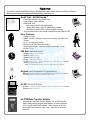
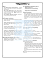
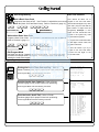
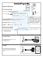
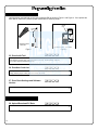
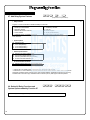
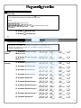
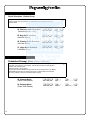
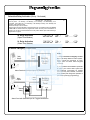
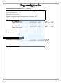
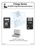
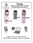
Trilogy Series
DL3500 Programming Instructions
ALARM LOCK
ALARM LOCK
AL-DTM
DATA TRANSFER MODULE
AR-IR1 PRINTER
DL3500 Trilogy Series
Standalone Access Control System
© ALARM LOCK 2000
WI1005A 08/00
1
Features -----------------------------------------------------------------------------------------------------4
Audit Trail -------------------------------------------------------------------------------------------------4
User Features -------------------------------------------------------------------------------------------4
500 Scheduled Events --------------------------------------------------------------------------------4
Keypad and Computer Programming --------------------------------------------------------------4
AL-IR1 Infrared Printer --------------------------------------------------------------------------------4
AL-DTM Data Transfer Module ---------------------------------------------------------------------4
Additional Features -----------------------------------------------------------------------------------5
Ambush Function ---------------------------------------------------------------------------------------5
User Associated for more than one Group ------------------------------------------------------5
Service Code --------------------------------------------------------------------------------------------5
Keypad Lockout ----------------------------------------------------------------------------------------5
Non-Volatile Memory ----------------------------------------------------------------------------------5
Error Checking ------------------------------------------------------------------------------------------5
Real Time clock -----------------------------------------------------------------------------------------5
Programmable Relay Functions --------------------------------------------------------------------5
Programmable Timeout Functions -----------------------------------------------------------------5
Advanced Features -----------------------------------------------------------------------------------5
Group 1 Initiated Functions --------------------------------------------------------------------------5
Wiring and Power Up ---------------------------------------------------------------------------------6
Wiring -----------------------------------------------------------------------------------------------------6
Self Diagnostic Indications --------------------------------------------------------------------------6
Battery Replacement ----------------------------------------------------------------------------------6
Power Up - Retain Lock Information --------------------------------------------------------------6
Power Up - Erase all Programming ----------------------------------------------------------------6
Preliminary Information -----------------------------------------------------------------------------7
Lock Operation -----------------------------------------------------------------------------------------7
Programming Notes ------------------------------------------------------------------------------------7
Visible LED and Audible Sounder Indicators ----------------------------------------------------7
Getting Started -------------------------------------------------------------------------------------------8
Battery Installation -------------------------------------------------------------------------------------8
Entering Program Mode ------------------------------------------------------------------------------8
Setting the Clock ---------------------------------------------------------------------------------------8
User Programming -------------------------------------------------------------------------------------9
Printer Functions
----------------------------------------------------------------------------------------------------- 9
Printing Time, Date and Day ------------------------------------------------------------------------9
Printing User Code List -------------------------------------------------------------------------------9
Printing the Audit Trail ---------------------------------------------------------------------------------9
2
Function Number
1. New Master Code --------------------------------------------------------------------------------------------11
2. Add/Delete/Change User Codes --------------------------------------------------------------------------11
3.-4. User Enable/Disable -----------------------------------------------------------------------------------------12
5. User Enable with Timeout -----------------------------------------------------------------------------------12
6.-7. User Lockout Mode ------------------------------------------------------------------------------------------12
9. Enable User 300 (Service Code) -------------------------------------------------------------------------12
10. Erase All Users Except the Master Code ---------------------------------------------------------------12
12. Clear All Schedules and Timeout Functions ------------------------------------------------------------13
13. Clear All Timeout Functions --------------------------------------------------------------------------------13
14.-23. Group Enable/Disable ---------------------------------------------------------------------------------------13
25.-34. Group Enable/Disable with Timeout ----------------------------------------------------------------------14
35. Group Add/Delete Association ----------------------------------------------------------------------------14
38. Set Date ---------------------------------------------------------------------------------------------------------15
39. Set Time ---------------------------------------------------------------------------------------------------------15
40. Set Weekday ---------------------------------------------------------------------------------------------------15
41. Set Daylight Savings Time ---------------------------------------------------------------------------------15
43.-44. Clock Adjust -----------------------------------------------------------------------------------------------------16
45.-46. Passage Mode Enable/Disable - Schedule will Override -------------------------------------------16
47. Timed Passage Mode ----------------------------------------------------------------------------------------16
48.-50. Passage Mode Enable/Disable - Schedule will not Override --------------------------------------17
51. Passage Mode Configuration ------------------------------------------------------------------------------17
52.-54. Pass Time ------------------------------------------------------------------------------------------------------17
55.-57. Printer Functions ----------------------------------------------------------------------------------------------18
58. PC Computer Uploading/Downloading--------------------------------------------------------------------18
59. AL-DTM Door Number ---------------------------------------------------------------------------------------19
60.-61. Lockout ----------------------------------------------------------------------------------------------------------19
64.-65. Remote Input ---------------------------------------------------------------------------------------------------19
66. Ambush Code---------------------------------------------------------------------------------------------------19
67.-68. Relay / System Features -----------------------------------------------------------------------------------20
69.-70. Enter Key -------------------------------------------------------------------------------------------------------20
72.-73. Scheduled Passage Mode Unlock/Lock -----------------------------------------------------------------21
74.-83. Scheduled Group Enable/Disable -------------------------------------------------------------------------21
84.-87. Quick Schedules -----------------------------------------------------------------------------------------------22
88.-89. Scheduled Passage Mode - Group 1 Activated--------------------------------------------------------22
90.-91. Scheduled Relay Activation - Group 1 Activated ------------------------------------------------------23
92.-93. Scheduled Group 4 Enable - Group 1 Activated -------------------------------------------------------24
99. Clear Programming -------------------------------------------------------------------------------------------24
Using Advanced Features -------------------------------------------------------------------------------25
Programming Record Sheet ----------------------------------------------------------------------------26
User Code Record Sheet----------------------------------------------------------------------------------27
Schedule Record Sheet -----------------------------------------------------------------------------------28
Definitions -----------------------------------------------------------------------------------------------------29
Warranty --------------------------------------------------------------------------------------------------------32
3
The Alarm Lock DL-3500 Series Trilogy Standalone Access Control System is a State-Of-The-Art
Microprocessor Based Programmable Keypad-Entry Security Lock.
------- AUDIT LOG ------04/07/98 13:06:35 Tue
13:01:59 001 PROGRAM 56
13:01:29 001 PROGRAM 57
13:00:53 001 ENTRY
13:00:26 013 ENTRY
13:00:03 012 ENTRY
12:56:27 001 PROGRAM 2
12:56:27 001 PROGRAM 40
12:56:04 001 PROGRAM 39
12:55:00 NEW CLCK TIME
12:01:39 OLD CLCK TIME
12:00:45 RAM TEST:PASS
12:00:45 POWER UP
------------------------End of Audit Log
Audit Trail - 40,000 Events *
• Time/Date Stamped Log of all Entries
• Logs program mode changes
• View Audit Trail:
Print using the AL-IR1 hand-held printer
Upload using Alarm Lock's DL-WINDOWS Software
Use Alarm Locks AL-DTM to upload multiple lock logs.
* Only the most recent 1,600 events are transferred using the AL-DTM.
User Features
• 300 User Codes
• Master, Installer, Manager, Supervisor, Print Only and Basic User
Codes
• 3, 4, 5 or 6 digit User Codes
• Service Code (One-Time-Only Code)
• User Lockout Mode - Total user lockout except User 1 code
• 4 User Groups
500 Scheduled Events *
• Programmed to Unlock/Lock
• Enable/Disable Users
• Enable/Disable Groups
• Group 1 Activated Events
• 4 "Quick Schedules" - allows programming of the 4 most common
time schedules in one step
* Only 150 scheduled events may be programmed using the
Keypad and Computer Programming
All programming may be done manually from the keypad, or from a
PC using Alarm Lock's DL-Windows Software.
AL-IR1 Infrared Printer
Optional hand-held infrared printer may be used to print the Audit
Trail and User Code List.
ALARM LOCK
AL-DTM Data Transfer Module
Optional Hand-held Data Transfer Module. The AL-DTM may be
used to easily transfer program data between up to 48 locks and a
PC running DL-WINDOWS software. Easily transfer Audit Trail
from multiple locks and then view or print each Audit Trail from a
computer.
4
Ambush Function
1. Connect relay to a device able to properly monitor dry
contacts for an ambush condition.
2. Program the Relay for Ambush Function Activated
using Program Function 67(10).
3. Set the Ambush Code using Program Function 66.
4. When the ambush code is entered followed by a valid
user code, the relay will close for 2 seconds.
Ambush Code
The ambush code defaults to 99.
User Code
An error will sound if you try to program a new user
code starting with the ambush code.
Keypad Lockout
Programmable number of attempts before keypad lockout.
Programmable lockout time.
Non-Volatile Memory
All programming is stored in non-volatile memory.
Error Checking
Extensive keypad program error checking reduces the
likelihood of a programming error.
Real Time Clock
Real time clock allows logging of events to within one
second accuracy. Unique feature (Functions 43/44) allows
speeding up or slowing down the clock providing long term
accuracy of the clock functions to within 3 minutes per year.
Users Associated for more than one group
If a user is associated with more than one group, all
associated groups would have to be disabled before the
user is disabled.
Service Code
User number 300 is the service code. Once the service
code is used, it is disabled. Function 9 or User Number
297 is used to re-enable the service code.
Group 1 Member puts unit in Passage Mode
Feature (88 & 89)
1. Use Function 88 to set an Open Time Window. The
lock will unlock (Passage Mode) when any Group 1
Member enters a code.
2. Use Function 89 to set the time to close the window.
Note: Passage Mode will have to be disabled each
night using Function 46 or schedule Function 73.
Example: Open window at 7:00AM using function 88,
Close Window at 8:30AM using function 89.
Lock will unlock when a member of group 1 enters their
code between 7:00AM and 8:30AM. If no group 1
member arrives between 7:00AM and 8:30AM, the lock
will stay locked all day.
Group 1 Member Disarms Burglary Control
Panel (90 & 91)
1. Connect relay to a burglar control panel with switch
input for disarming.
2. Use Function 90 to set the time to open the window
allowing any Group 1 Member to close the relay
for 2 seconds. Note: Only 1 relay closure will occur
even if another member of group 1 enters their code.
Programmable Relay Functions
Relay may be programmed to energize when one or more
selected events occur.
Programmable Timeout Functions
Timeout functions allow enabling/disabling users and
enabling passage mode for a time period without requiring
3. Use Function 91 to set the time to close the window.
Note: The alarm panel will have to be armed at night by
the user or by an automatic schedule function of
the alarm panel.
Example: Open window at 7:00AM using program
Function 90, Close Window at 8:30AM using Function
91.
The relay will close, one time only, when a member of
group 1 enters their code between 7:00AM and 8:30AM.
Group 1 Member Enables Group 4 Users
1. Use Function 92 to set the time to open the window
allowing any group 1 member to enable group 4.
2. Use Function 93 to set the time to close the window.
Note: Group 4 will have to be disabled each night using
Function 17 or schedule Function 82. Example: Open
window at 7:00AM using Function 92, close window at
8:30AM using Function 93.Group 4 will be enabled when
a member of group 1 enters their code between 7:00AM
and 8:30AM (group 4 users will have to wait outside until
a manager arrives to enable their codes. If a manager
does not arrive between 7:00AM and 8:30AM, group 4 is
not enabled.
5
Wiring
Red / Black (Operation without Batteries) - Optional
External 7.5 VDC Power Source must be used for operation
without batteries.
White / White (Remote Input) - Wire a Normally Open
Contact to wires (white and white). Momentarily close to allow
person to pass through door. NOTE: Remote Input is
enabled from the factory.
Relay: COM-Blue / NO-Yellow / NC-Green - See Function
67 for programming options for the Relay.
Self Diagnostic Indications
Various system tests are performed at power up and during
operation of the lock.
Steady 4 Second Sounder with a Yellow LED indication
every time a user code is entered - indicates a Low
Battery Condition.
Continuous Series of Beeps - indicates the lock detected
a system fault which would not allow any part of the system
to operate. Ensure batteries are good.
Sequence of 7 Beeps Repeated 4 Times with a Yellow
LED indication, every time a user code is entered indicates a non-fatal memory or clock error has been
detected. Under this condition, unexpected operation is
possible. Do not mistake the low battery indication as a
memory or clock error.
Wiring to Disarm a Burglary Control Panel
See illustration on connecting the DL3500 to an Alarm Panel.
Scheduled Relay Activation - Group 1 Activated
(Function 90/91) on on page 23.
6
The Three Methods of Powering Up are:
•
Battery Replacement
Power-Up Retain Lock Programming
• Power-Up Erase All Programming
•
Battery Replacement
When a valid code is entered and the batteries are weak the
lock LED will display a yellow color, and the sounder will
sound for 4 seconds. The DL3500 uses 5 AA-size 1.5 volt
alkaline batteries. The lock will function with weak batteries;
however be sure to replace the batteries as soon as
possible.
Remove the screw at the bottom of the housing and remove
the cover. Pull out the battery pack and replace all 5
batteries quickly - within 1 minute. Note: Do not press any
buttons while replacing the batteries (unless lock
programming is to be erased). Pressing any key will remove
the voltage that is required to keep the system clock.
Power-Up - Retain Lock Programming
(Clock Settings lost)
1. Disconnect battery pack connector.
2. Press any key to insure the locks capacitor is fully
discharged.
3. Re-install battery pack (lock will give 3 short beeps).
4. Do not press any keys for 10 seconds.
5. After the 15 second period the LED will flash red 6 times
and 6 beeps will sound.
The lock is now ready for use. Program is loaded from nonvolatile memory. Set the clock using functions 38, 39 and 40.
Power-Up - Erase All Programming
(Factory Default will be loaded)
1. Remove the battery pack.
2. Press any key to insure locks capacitor is fully discharged.
3. Re-install the battery pack (lock will give 3 short beeps).
4. Press any key within 5 sec after hearing the 3 beeps.
5. A series of 5 RED LED and 5 beeps will be heard
followed by 10 seconds of silence, 3 GREEN LED and 3
fast beeps.
All programming has been erased and the lock is now ready
for use.
Note: All lock programming can also be erased by entering
Function 99.
Lock Operation
Important: Before attempting to program any codes or
functions, Note the following:
• While the lever or knob may be rotated at any time, the latch
will not be engaged to unlock the door unless a valid code has
been entered.
• When a valid code is entered, the lock will unlock immediately
and remain unlocked for about 3 seconds (or longer, if
reprogrammed by functions 53 and 54).
Programming - Notes
It is recommended that all programming be prepared in advance
using the DL3500 Programming Sheets for reference while
programming (see User Code and Schedule Recording sheets
at the back of this manual), then be secured when finished.
PROGRAM LEVELS
You must have the programming authority level equal to the
authority level required to access a programming function.
Programming authority levels can have a value of 1, 2, 3, 4 or M.
A programming authority level of M (Master) is associated with
the Master Code and cannot be associated with any other user.
CODE TYPES
Program level ability is fixed according to table on page 11. The
codes are defaulted to the tabulated group associations when
adding codes using Program Function 2.
Master Code - User 1: Always enabled and can program all
functions, can't be group associated.
Installer Codes - Users 2 & 3: Allow all functions except
master code change.
Manager Codes - Users 4 - 6: Can program all functions
except functions relating to lock configuration, no default group
association.
Supervisors - User 7 - 9: Can only program functions relating
to day to day operation, no default group association.
Print Only Codes - Users 10 & 11: Allow access to print audit
trail only.
Basic User Codes: No program ability, default group
association.
Visible LED and Audible Sounder Indicators
Activity
Keypress
Enter Valid Enabled Code
Enter Invalid No/Wrong Code
Successful Program Entry
Unsuccessful Program Entry
Normal Battery
LED
SOUNDER
1 RED Flash
1 Beep
3 GRN Flashes
3 Beeps
6 RED Flashes
6 Beeps
2 GRN Flashes
2 Beeps
7 RED Flashes
7 Beeps
Low Battery is indicated by a Yellow Flash during Key Press and a Long Beep.
Function Name
Enabling/Disabling Users (By User Number)
•
Programming
Information
User Number must be between 2 and 300.
NOTE: Will Enable/Disable users even if the user is associated with a enabled group.
2
3. Disable User
;3
;[___]:
4. Enable User
;4
;[___]:
Program Level Required - The
program level required to access
the
Function.
Possible
Programming Levels of 1,2,3,4 and
M, where M = Master Code.
Program Authority Level of User
must be equal to the Function that
is to be accessed.
Programming key sequence.
General Program Mode Information
If a wrong key is pressed during code entry, hold any key continuously until the error sound is heard (7 short beeps),
this will clear the entry, then re-enter the key sequence again.
7
Battery Installation
Remove the back cover and install battery pack. The lock will
beep 3 times. To load the default program press any key within
5 seconds, the lock will beep slowly while the default values are
loaded and beep rapidly upon completion.
Entering Program Mode
1. Enter Master Code 1 2 3 4 5 6
Program Mode
Default Master Code
The keypad sounder will beep every 6 seconds
and the keypad LED will flash green every 6
seconds while in program mode when no keys
are pressed.
NOTE: There is a 3 minute
Timeout if no keys are pressed while in
Program Mode.
2. Press and hold ; until 8 beeps are sounded.
Program a new Master Code.
;1
;
[______]
;
New Master Code
[______]:
Confirm New Master Code
Setting the Clock - While still in Program Mode enter the following commands to set the clock.
For Example: August 25, 2000;
Enter:
Program the Date.
;38
;
[______]:
;38
;08
08
00:
Date
For Example: To set time to 8:25 P.M.;
Enter: ; 3 9
Program the Time.
;39
;
[____]:
Time
Program the Weekday.
;40
;
;2025:
For Example: To set time to 8:25 A.M.;
Enter: ; 3 9
; 0 8 2 5:
For day enter: 1 for Sunday, 2 for Monday, 3 for Tuesday, 4 for Wednesday,
5 for Thursday, 6 for Friday and 7 for Saturday.
[_]:
Day
Program Daylight Saving Time.
;41
;
[__]:
DST Mode
8
For Example: To program the Default DST Mode;
Enter:
;41
;12:
User Programming
User code conflicts
Add a Basic User Code
Care should be taken not to
Program a User Code of 987. Use Function 2, and add the new user as program a new user code which
User 12 (Users 12-50 are Basic Users). Refer to Function 2 (page 11). matches the first digits of any other
;2
;12
;987:
User Number (12)
User 12’s Code
Add another Basic User Code
user code. (only the code with the
least number of digits would be
recognized). Example: If user
codes 123 and 123456 are both
entered in the system only code
123 would be recognized.
Program a User Code of 246. Use Function 2, and add the new user as User 13.
Refer to Function 2 (page 11).
To program user codes that match
;2
;13
;246:
User Number (13)
User 13’s Code
Exit Program Mode
Hold down any key for 3 seconds to exit Program Mode. The Lock is now ready
to function as a simple Audit Trail System. Test each new User Code added by
entering the code at the keypad.
the first digits of other codes, see
program Function 69.
An error will sound if you try to
program a new user code which
matches the first digits of the
Master User Code.
Printer Functions (AR-IR1 PRINTER required)
Printing the Lock’s Time, Date and Day. Refer to
Printer Functions (page 18) for proper Printer-Lock positioning.
From Program Mode enter the following command:
;57:
ALARM LOCK SYSTEMS, INC
VERSION 8.02 org REC
08/25/00 13:11:28 Fri
Clock adjust setting +0
Cycle count hex 00000E
F39 day ct hex
00
ALARMLOCK
Print the Lock’s User Code List. Refer to Printer
08/25/00 13:06:35 Fri
Functions (page 18) for proper Printer-Lock positioning.
USER|USER
NUM |CODE
From Program Mode enter the following command:
1 123456
12 987
13 246
|GROUP|PROG
|
|LEVL
....
....
....
1234
....
....
;56:
Print the Lock’s Audit Trail. Refer to Printer
Functions (page 18) for proper Printer-Lock positioning.
From Program Mode enter the following command:
;55:
------- AUDIT LOG ------08/25/00 13:06:35 Fri
13:01:59 001 PROGRAM 56
13:01:29 001 PROGRAM 57
13:00:53 001 ENTRY
13:00:26 013 ENTRY
13:00:03 012 ENTRY
12:56:27 001 PROGRAM 2
12:56:27 001 PROGRAM 40
12:56:04 001 PROGRAM 39
12:55:00 NEW CLCK TIME
12:01:39 OLD CLCK TIME
12:01:30 001 PROGRAM 38
12:01:30 DATE CHANGED
12:01:07 001 ENTRY
12:00:48 CLK TEST:PASS
12:00:45 RAM TEST:PASS
12:00:45 POWER UP
------------------------End of Audit Log
9
Tri-Color
Keypad Programming
Infrared LED
Entering Program Mode
PC Interface/AL-DTM
1. Enter Master Code 1 2 3 4 5 6
Default Master Code
“BeepBeep” “BeepBeep”
2. Press and hold ;
“BeepBeep” “BeepBeep”
Sounder will sound 2 short beeps 4 times to indicate
the program mode is active.
Program Mode
The keypad sounder will beep every 6 seconds
and the keypad LED will flash green every 6
seconds while in program mode when no keys
are pressed.
NOTE: There is a 3 minute
Program Mode Timeout if no keys are pressed
while in Program Mode. A steady tone will
sound indicating there is 15 seconds left to
press a key or Program Mode will timeout.
Program the Master Code before programming any other
Functions (New Lock or following a power up).
New Master Code (User Number 1)
;1
;
[______]
New Master Code
;
[______]:
Confirm Master Code
Exiting Program Mode
There are 2 ways to exit Program Mode:
1. Hold down any key for 3 seconds
2. Press no keys for 3 minutes
(Program Mode Timeout).
2 series of 4 Quick Beeps once
the Exit Sequence has initiated.
“BeepBeepBeepBeep”
“BeepBeepBeepBeep”
Communication
TO SERIAL PORT (DB-9)
E.G. <COM 1>
+
The DL3500 lock can also be programmed using
a computer and Alarm Lock's
DL-WINDOWS Software.
AL-PCI
NOTE: Observe Tab Direction
when inserting cable into DL3500 Lock.
-
DL3500 Lock (mounted on door)
IBM COMPATIBLE
LAPTOP COMPUTER
AL-DTM
PLUG IN THEN
ENTER YOUR CODE
+
-
NOTE: Observe Tab Direction
when inserting cable into DL3500 Lock.
-
(Tab to the left)
DL3500 Lock (mounted on door)
10
+
The DL3500 lock can also be programmed using
Alarm Lock's AL-DTM Data Transfer Module and
a computer running Alarm Lock's DL-WINDOWS
Software.
AL-DTM
Note: AL-DTM
has
been
configured using
a
computer
running
DLW I N D O W S
software. Refer to
D L - WINDOWS
S o f t w a r e
USERS
;1
1. New Master Code (User Number 1)
;[______]
;[______]:
(New Master Code)
• Master Code must be 6 digits-only.
(Confirm New Master Code)
M
2. Add/Delete/Change User Codes 2-300
;2
;[___]
;[______]:
(User Number)
• User Number must be between 2 and 300.
• To delete a code, leave the User Code blank
• User Code must be 3-6 digits
(User Code)
3
Users programmed with Function 2 will default to a Group
Association and a Program Level Ability as follows:
USER TYPE
USER NUMBER
GROUP DEFAULT
ASSOCIATION
PROGRAM
LEVEL ABILITY
1
-
1, 2, 3, 4, Master
Installer Codes
2&3
none
1, 2, 3, 4
Manager Codes
4-6
none
1, 2, 3
Supervisor Codes
7-9
none
1, 2
Print Only Codes
10 - 11
none
1
Basic User Codes
12 - 50
none
none
Basic User Codes Group 1
51 - 100
1
none
Basic User Codes Group 2
101 - 150
2
none
Basic User Codes Group 3
151 - 200
3
none
Basic User Codes Group 4
201 - 250
4
none
Basic User Codes
251 - 296
none
none
Quick Enable User 300 Code
297
none
none
Quick PC Access Code
298
none
none
AL-DTM Code
299
none
none
Service Code
300
none
none
Master Code
NOTE:
User 299 is a Non-Pass Code. This is the only code that will initiate data transfer with the AL-DTM.
11
User Enable/Disable (By User Number)
• User Number must be between 2 and 300
NOTE: Will Enable/Disable users even if the user is associated with an enabled group.
;3
3. Disable User
2
;
[___]:
(User Number)
;4
4. Enable User
;
[___]:
(User Number)
USERS
;5
5. User Enable with Timeout
;[___]
• User Numbers must be between 2-299
• Hours must be between 1 - 999
;[___]:
(User Number)
(Enter Timeout, XXX Hours)
• Can override a disabled user
(XXX Hours)
2
User Lockout Mode
Enables/Disables all User Codes (Except User 1 Code) from operating the lock. Note: No other
programming functions or schedules will re-enable users. Users must be re-enabled with function 7.
6. Enable Total User Lockout
;6:
7. Disable Total User Lockout
;7:
M
8. Reserved
9. Enable User 300 (Service Code)
;9:
Service Code is a One-Time-Only Code. Once it is used, it is disabled until enabled again.
NOTE: User Number 297 can also be used to reset Service Code Use.
10. Erase All Users Except the Master Code
Erases all user codes except the Master Code (User 1).
11. Reserved
12
;10
2
;000:
M
CLEAR FUNCTIONS
12. Clear All Schedules and Timeout
;12
;000:
Clears all programmed Schedules and all Timeout Functions. Includes Schedule Functions 72 to 93.
Includes Timeout Functions 5, 25 to 34 and Function 47. NOTE: Up to 4 Timeout Functions may be
pending at any one time. An error beep will sound if more than 4 Timeout Functions are attempted to
be programmed. Scheduled/Timeout features must be manually reset.
13. Clear All Timeout Functions
;13
3
;000:
Clears all programmed Timeout Functions. Includes functions 5, 25 to 34 and Function 47.
NOTE: Only 4 Timeout Functions are allowed at any one time. An error beep will sound if more than
4 Timeout Functions are attempted to be programmed. Timeout features must be manually reset.
3
GROUPS
Group Enable/Disable
Enter the functions below to Enable/Disable Groups.
2
14. Disable Group 1
;14:
15. Disable Group 2
;15:
16. Disable Group 3
;16:
1. Disabled Users
17. Disable Group 4
;17:
2. Enabled Groups
18. Disable All Groups
;18:
19. Enable Group 1
;19:
20. Enable Group 2
;20:
21. Enable Group 3
;21:
22. Enable Group 4
;22:
23. Enable All Groups
;23:
Priority Order
3. Disabled Groups
4. Enabled Users
24. Reserved
13
NOTE:
GROUPS
Clear All Timeout Functions by entering Function 13.
Group Enable/Disable with Timeout (Enter Timeout, XXX Hours)
• Hours must be between 1 - 999.
• Enter the functions below to Enable/Disable groups for the amount of time entered in
hours. NOTE: Only 4 Timeout Functions are allowed at any one time. An error beep will
sound if more than 4 Timeout Functions are attempted to be programmed.
25. Timed Disable Group 1
;25
2
;
[___]:
(XXX Hours)
26. Timed Disable Group 2
;26
;
[___]:
(XXX Hours)
27. Timed Disable Group 3
;27
;
[___]:
(XXX Hours)
28. Timed Disable Group 4
;28
;
[___]:
(XXX Hours)
29. Timed Disable All Groups
;29
;
[___]:
(XXX Hours)
30. Timed Enable Group 1
;30
;
[___]:
(XXX Hours)
31. Timed Enable Group 2
;31
;
[___]:
(XXX Hours)
32. Timed Enable Group 3
;32
;
[___]:
(XXX Hours)
33. Timed Enable Group 4
;33
;
[___]:
(XXX Hours)
34. Timed Enable All Groups
;34
;
[___]:
(XXX Hours)
35. Group Add/Delete Association
; 35
;[___]
;[____]:
(User Number)
• Groups that are not Selected are then Disassociated from the User (See Default Group
Association on page 11.
• User Number must be between 2 and 300.
• 1 or more (1-4) groups to associate with user may be selected.
Add Example: To associate user 67 with groups 1, 2 and 4;
Enter:
;35
;67
;124:
Delete Example: To remove all group associations for user 67;
Enter:
36 - 37. Reserved
14
3
(Groups)
CLOCK SETTINGS
;38
38. Set Date
;
[______]:
(Date)
• Use month day year format - MMDDYY - single digit months and days are entered with a
preceding zero.
• Enter Only the last two digits of the year.
3
For Example: August. 25, 2000;
Enter:
;38
;08
25
00:
;39
39. Set Time
;
[____]:
(Time)
• Time must be 4 digits.
• Use 24 Hour Format (add 12 hours to program P.M. time)
3
For Example: To set time to 8:25 P.M.;
Enter: ; 3 9
;2025:
For Example: To set time to 8:25 A.M.;
Enter: ; 3 9
;0825:
;40
40. Set Weekday
;
[_]:
(Day)
• For day enter: 1 for Sunday, 2 for Monday, 3 for Tuesday, 4 for Wednesday, 5 for Thursday, 6
for Friday and 7 for Saturday.
3
For Example: To set day to Sunday;
Enter: ; 4 0
;1:
;41;
41. Set Daylight Savings Time
[__]:
(DST Mode)
NOTE: Daylight Savings Time (DST) Adjustment is programmable as shown in the table below. All
modes adjust time at 2AM. * Default DST Mode is 12.
DST Mode
01
Time Forwarded
Time Regressed
DST Mode
Time Forwarded
Time Regressed
13
Last Friday in April
Last Thurs. in Sept.
02
03
04
1st Sunday in March
Last Sat. in March
Last Sunday in March
4th Tuesday in Sept.
Last Sat. in Sept.
Last Sunday in Sept.
14
15
16
May 1st
1st Sunday in Sept.
2nd Tuesday in Sept.
September 30th
1st Sunday in April
3rd Tuesday in April
05
06
07
Last Sunday in March
Last Sunday in March
Last Sunday in March
4th Sunday in Oct.
Last Sunday in Oct.
1st Sunday in Sept.
17
18
19
1st Sunday in Oct.
1st Sunday in Oct.
1st Sunday in Oct.
Last Sunday in Feb.
3rd Sunday in March
Last Sunday in Mar.
08
09
10
April 1st
April 1st
April 1st
September 30th
October 1st
Last Sunday in Oct.
20
21
22
2nd Sunday in Oct.
3rd Sunday in Oct.
Last Sunday in Oct.
2nd Sunday in Mar.
2nd Sunday in Feb.
1st Sunday in March
11
* 12 (U.S.A. &
Canada)
1st Sunday in April
1st Sunday in April
2nd Sunday in Oct.
Last Sunday in Oct.
23
24
Last Sunday in Oct.
1st Sunday in Nov.
Last Sunday in Mar.
Last Sunday in Feb.
42. Reserved
No DST Adjustment
4
15
CLOCK ADJUST
Clock Adjust
• Number of seconds to Speed Up/Slow Down clock each day must be 0-55 seconds.
Always consider the current setting when using this function. (Use of this function is not
cumulative.) For example, if the clock needs to be sped up 10 seconds per day and the
current setting is 10, program 20 seconds using Function 43.
4
Example 1: Clock is losing 13 seconds every day, enter:
;43
; 1 3 :.
This example assumes that the clock adjust setting was at the factory default of zero.
Function 57 can be used to print the current clock adjust setting.
Example 2: Clock is gaining 13 seconds every day, enter:
;44
; 1 3 :.
This example assumes that the clock adjust setting was at the factory default of zero.
Function 57 can be used to print the current clock adjust setting.
Example 3: To set the clock adjust setting back to the factory default of zero, enter:
; 4 3 : or ; 4 4 :
43. Speed Up Clock
;43
;
[_ _]:
(seconds)
44. Slow Down Clock
;44
;
[_ _]:
(seconds)
PASSAGE MODE
Passage Mode Enable/Disable - Schedule will Override
• Allows passage through the door without the need for a code using Function 45. Re-Lock
using Function 46.
• Programmed Schedules will override the state of the lock using functions 45 and 46. If it
is required that programmed schedules do not override passage mode, Enable/Disable
45. Enable Passage Mode
;45:
46. Disable Passage Mode
;46:
47. Timed Passage Mode
;47
;
• Hours must be between 1 - 999.
Allows passage through the door without the need for a code for the programmed amount of
time.
16
2
[___]:
(XXX Hours)
2
PASSAGE MODE
Passage Mode Enable/Disable - Schedule will not Override
• Allows passage through the door without the need for a code using Function 48. Re-Lock
using Function 49.
• Programmed Schedules will not override the state of the lock using functions 48 and 49.
If it is required that programmed schedules do override passage mode, Enable/Disable
Passage mode using Functions 45/46. Use Function 50 to return the lock to scheduled
functions.
48. Enable Passage Mode
;48:
49. Disable Passage Mode
;49:
50. Return Lock to Normal
Passage Mode Schedule
;50:
2
(The DL3500 will lock or unlock
depending on the current schedule.)
NOTE:
See Scheduled functions 72 and 73 for scheduled passage mode.
51. Passage Mode Configuration
;51;
:
[_]
(Mode)
Mode 1 (Normal): Passage mode must be enabled/disabled using function 45 and 46.
Mode 2: Group 2 toggles passage mode.
Mode 3: Group 2 enables, Group 3 disables passage mode *
* Disable passage mode has priority if user is a member of both groups 2 and 3.
PASS TIME
Pass Time
Use the functions below to change the pass time to 3, 10 or 15 seconds. The Pass Time is
defaulted to 3 seconds. The Pass Time is the time the lock stays unlocked after a User Code
is entered.
52. Set Pass Time to 3 Sec.
;52:
53. Set Pass Time to 10 Sec.
;53:
54. Set Pass Time to 15 Sec.
;54:
4
17
PRINTER
Hold the printer perpendicular to the Lock’s infrared LED as shown in Figure 1 and Figure 2. If the printer has
been idle for some time, press the paper feed button to wake up printer.
Infrared
LED
Infrared
LED
123
456
789
:0;
DL3500 to Printer
- Side View
DL3500 to Printer - Front View
Figure 1
55. Print Audit Trail
Figure 2
;55:
Hold the printer over the lock's infrared sensor as shown in Figure 1 and Figure 2. 20
events will print at a time; press 1 for more events, or 9 to quit. To abort printing, press any
key for 3 Sec (Three short beeps will sound).
56. Print User Code List
;56:
Hold the printer over the lock's infrared sensor as shown in Figure 1 and Figure 2. To abort
printing, press any key for 3 Sec (Three short beeps will sound).
57. Print Clock Settings and Software
Version
1
3
;57:
Hold the printer over the lock's infrared sensor as shown in Figure 1 and Figure 2.
1
DOWNLOADING
58. Upload/Download PC Data
;58:
For use with DL-WINDOWS software, refer to OI237. AL-PCI interface cable is needed.
18
3
AL-DTM
59. AL-DTM Door Number
;59
;
[__]:
Door Number)
• Door Number must be between 1- 48.
4
For use with Alarm Lock’s AL-DTM Data Transfer Module. Using the AL-DTM up to 48
locks can be Downloaded/Uploaded and History LOGs can be retrieved. Enter a door
number for each lock. After configuring the AL-DTM, using Alarm Lock's DL-WINDOWS
Software, any of the following data transfers can be initiated by plugging the AL-DTM into
the lock and simply entering User Code 299 at the lock.
• Upload Lock Program
• Upload History LOG
• Download Lock Program
LOCKOUT
60. Number of Attempt Before Lockout
;60
;
[_]:
(Number of Attempts)
• Number of attempts before lockout must be 1-9 attempts.
• The number of attempts is reduced by half every time the keypad is locked out without a
successful code entry (default is 6 attempts).
• The attempt count is reset each time a valid code is entered.
61. Set the Attempts Lockout Time
;61
4
;
[__]:
(Lockout Time)
• Lockout Time must be 1-60 seconds.
How long the keypad is locked out after a series of unsuccessful attempts (default is 15
seconds).
4
62-63. Reserved
REMOTE INPUT
Remote Input
• Wire a Normally Open Contact to Wires (White & White). Momentarily close to allow person to pass
through door.
• Enter the functions below to Disable/Enable the Remote Input.
NOTE: The Remote Input is enabled as part of the default program.
64. Disable Remote Input
;64:
65. Enable Remote Input
;65:
2
AMBUSH
66. Ambush Code
;66
;
[_ _]:
(Ambush Code)
• Ambush code must be 2 digits.
• An error will sound if the ambush code matches the 1st two digits of any user code. See
Using Ambush Function on page 5.
3
19
RELAY / SYSTEM FEATURES
67. Add Relay/System Features
;67
;
[__]:
(Relay Function / System Feature)
4
• Relay Functions
Program 1 or more events below to activate the Relay for 2 seconds.
1.
2.
3.
4.
5.
6.
Remote Input while enabled
Remote Input while disabled
Failed Entry Attempt
Disabled User entered code/card
Access Granted
Scheduled (Group 1 Activated) Function 90
7. Locked by Schedule
8. Unlocked by Schedule
9. Lock Out
10. Ambush Tripped
11. Any key press/card entry
31. Relay Follows Lock/Unlock Status **
12-24. Reserved
• System Options
25.
26.
27.
28.
Disable Sounder
5 sec. Delayed Entry *
15 sec. Delayed Entry *
45 sec. Delayed Entry *
• Remote Input Functions
29.
30.
32.
34.
Remote Input Toggles Passage Mode
Forced Unlock Follows Remote Input **
Remote Input Disables Unit (Hold all States)
Forced Lock Follows Remote Input **
• PC Communication Functions
33. Remote Input Puts Unit in PC Communication Mode
* Features 26, 27 & 28 delay users 12 and greater only, except 297, 298 and 299.
** Features 30, 31, 32 & 34 should be used with External DC Power unless feature is used for short a duration and
infrequently (sustained closure of remote input or relay will drain batteries. Scheduled events will not occur during
sustained closure of remote input). Sustained closure of remote input may affect proper audit trail operation.
68. Delete All Relay Functions and
System Options added by Function 67
Delete all Relay Functions programmed by Function 67.
20
;68
;000:
4
ENTER KEY
Enter Key
• When this function is enabled the user must press the : key after any valid user code
entry, this allows user codes which are subsets of other user codes.
4
Example:
1 2 3 : is a valid user code;
1 2 3 4 : is a valid user code
1 2 3 4 5 6 : (hold ; ) for Master User Code to enter
Program Mode.
69. Enable : as Enter Key
70. Disable : as Enter Key
71.
SCHEDULES
NOTE:
Clear All Schedule and Timeout Functions by entering Function 12.
Scheduled Passage Mode and Scheduled Groups
Use the functions below to Enable/Disable Groups at the time programmed.
• For day enter: 1 for Sunday, 2 for Monday, 3 for Tuesday, 4 for Wednesday, 5 for
Thursday, 6 for Friday and 7 for Saturday, 8 for Monday to Friday, 9 for Saturday and
Sunday, 0 for all days of week.
Passage
Mode
Groups
72. Schedule Enable Passage
Mode (Unlock)
;72
73. Schedule Disable Passage
Mode (Lock)
;73
74. Schedule Enable Group 1
;74
3
;[_]
(Day)
;[_]
(Day)
;[_]
(Day)
75. Schedule Enable Group
;75
;[_]
(Day)
76. Schedule Enable Group
;76
;[_]
(Day)
77. Schedule Enable Group
;77
;[_]
(Day)
78. Schedule Enable All
;78
;[_]
(Day)
79. Schedule Disable Group 1
;79
;[_]
(Day)
80. Schedule Disable Group 2
;80
;[_]
(Day)
81. Schedule Disable Group 3
;81
;[_]
(Day)
82. Schedule Disable Group 4
;82
;[_]
(Day)
83. Schedule Disable All
;83
;[_]
(Day)
;[____]:
(Time)
;[____]:
(Time)
;[____]:
(Time)
;[____]:
(Time)
;[____]:
(Time)
;[____]:
(Time)
;[____]:
(Time)
;[____]:
(Time)
;[____]:
(Time)
;[____]:
(Time)
;[____]:
(Time)
;[____]:
(Time)
21
QUICK SCHEDULES
Quick Schedules - Enable Group
• Group number must be 1-4
Enter the number of the group that is to be enabled for the time specified for the Quick
Schedules below:
84. Business Quick Schedule
;84
3
;[_]:
(Group)
7AM-5PM, Monday - Friday
85. Day Quick Schedule
;85
;[_]:
(Group)
7AM-5PM, All days
86. Evening Quick Schedule
;86
;[_]:
;87
;[_]:
3PM-1AM, All days
87. Night Quick Schedule
(Group)
11PM-9AM, All days
SCHEDULES GROUP 1 ACTIVATED
Scheduled Passage Mode (Group 1 Activated)
• For day enter: 1 for Sunday, 2 for Monday, 3 for Tuesday, 4 for Wednesday, 5 for
Thursday, 6 for Friday and 7 for Saturday, 8 for Monday to Friday, 9 for Saturday and
Sunday, 0 for all days of week.
• Enter time of day in 24 hour format.
Enter the Open and Close Window Functions below to set up a Window where if any Group
1 User Code is entered within the programmed window, Passage Mode will be activated.
See Group 1 Member in Puts Lock in Passage Mode on page 5.
22
3
88. Passage Mode
(Open Time Window)
;88
;[_]
;[____]:
89. Passage Mode
(Close Time Window)
;89
;[_]
;[____]:
(Day)
(Time)
SCHEDULES GROUP 1 ACTIVATED
Scheduled Relay Activation (Group 1 Activated)
• Also program Relay Function 6 using Function 67 (; 6 7 ; 6 :).
• For day enter: 1 for Sunday, 2 for Monday, 3 for Tuesday, 4 for Wednesday, 5 for
Thursday, 6 for Friday and 7 for Saturday, 8 for Monday to Friday, 9 for Saturday and
Sunday, 0 for all days of week.
• Enter time of day in 24 hour format.
Enter the Open and Close Window Functions below to set up a Window where if any Group
1 User Code is entered within the programmed window the relay will be activated for 2
seconds. For use with a Control Panel that has a key switch disarm option. See Disarming a
Burglar Alarm on page 5.
3
90. Relay Activation
(Open Time Window)
;90
;[_]
;[____]:
91. Relay Activation
(Close Time Window)
;91
;[_]
;[____]:
To Disarm a Burglary Control Panel
Notes:
Relay
Output
Switch
Input
Burglary
Control
Panel
2. Use a qualified electrical/alarm specialist
to review your current alarm system and
add additional components as needed
(such as a relay, wire, resistors, connectors
and/or diodes) and change the operation of
your alarm system (by programming).
Alarm Panel with Switched Input for Disarming
Relay
Output
External
Relay
Switch
Input
1. Group 1 Disarms a Burglary Control
Panel will always disarm an alarm system.
Arming should be performed by other
means (such as Alarm Panel Keypad/
Schedule).
Burglary
Control
Panel
Armed
Lug
Power
Alarm Panel with Switched Input for Toggled Arm/Disarm
23
Scheduled Group 4 Enable (Group 1 Activated)
• For day enter: 1 for Sunday, 2 for Monday, 3 for Tuesday, 4 for Wednesday, 5 for
Thursday, 6 for Friday and 7 for Saturday, 8 for Monday to Friday, 9 for Saturday and
Sunday, 0 for all days of week.
• Enter time of day in 24 hour format.
Enter the Open and Close Window Functions below to set up a Window where if any Group
1 User Code is entered within the programmed window Group 4 will be enabled. See
Group 1 Member enables Group 4 Members on page 5.
92. Enable Group 4
(Open Time Window)
;92
93. Enable Group 4
(Close Time Window)
;93
3
;[_]
;[____]:
(Day)
(Time)
;[_]
;[____]:
94 - 98. Reserved
CLEAR ALL PROGRAMMING
99. Clear All Lock Programming
Clears all programming. Audit Trail contents are maintained.
24
;99
;000:
M
Note:
Advanced User Programming
Add a User that is a member of Group 2 & Group 3
Program a User Code of 789 that is a member of Group 2. Refer to Function 2 (page 11). Use Function 2,
and add the new user as User 101 (Users 101-150 are members of Group 2):
Add User 101:
;2
;101
;789:
Make User 101 also member of Group 3 using Function 35:
;35
;101
;23:
Note: Although User 101 is by default a member of Group 2, Group 2 must be included when making changes to the
Group Association using Function 35 or the Group 2 association will be removed.
The example to add Users
to Group 2 and Group 3
has been selected due to
the fact that Group 1
Activated
Functions
require that a member a
Group 1 enter their code
to activate the function.
Do not add general users
to Group 1 if Manager
Initiated Functions are to
be
programmed
Functions 88/89, 90/91
and 92/93.
Group 1 Activated Features
Add a User to Group 1
Program a User Code of 456789 that is also a member of Group 1. Use Function 2, and add the new user as
User 4 (Manager).
Add User 4:
;2
;4
;456789:
Make User 4 a member of Group 1 by using Function 35:
;35
;4
;1:
Add Schedule that Opens the Lock (Passage Mode) when a member of Group 1 enters their code.
Program a schedule using Function 88 and Function 89 between the hours of 6 A.M. and 10 A.M. for all days of the week.
Enter the Open Window Time of 6 A.M.:
;88 ;0 ;0600:
Enter the Close Window Time of 10 A.M.: ; 8 9 ; 0
;1000:
The Lock will now be put in passage mode IF User 4 (or any Group 1 User) enters their code between 6 A.M. and 10 A.M.
To Change to a different
Group 1 Activated
Function.
Replace functions 88 & 89
(Passage Mode Enable)
with functions 90/91
(Burglar Alarm Disarm) or
92/93 (Group 4 Enable).
The Lock will have to be manually locked each night by entering the following command using Function 46.
Manually close the Lock by entering the following command:
;46:
The Lock can also be programmed to automatically close each night at 6 P.M. by adding a scheduled Lock Time using
Function 73:
Automatically (Scheduled Lock) close the Lock by entering the following command:
;73
;0
;1800:
Note:
Other Group 1 Initiated (Manager) Functions include:
Disarming a Burglar Alarm (Relay Activation) See functions 90/91.
Group 4 Enable - See functions 92/93.
25
Default Values are shown in parentheses.
Function Number(s) Function Name
41
Daylight Savings Time Code
43/44
Clock Adjust
52/53/54
Pass Time
59
AL-DTM Door Number
Programming
01-24
(1)
(2)
(0)
(0)
0-55
+/-
61
(1)
66
Ambush Code
1-9 Attempts
(6)
Attempts
(1)
(5)
1-60 seconds
Seconds
(Enable) •
Disable •
00-99
(9)
Add Relay/System Features
15 sec •
Door Number
Set Lockout Time
Remote Input Disable/Enable
10 sec •
1-48
Set Lockout Attempts
64/65
67
Seconds
(3 sec) •
(0)
60
DST Code
(9)
Ambush Code
Check all that apply
1. Remote Release while enabled
2. Remote Release while disabled
3. Entry Attempt (Failed)
4. Disabled user entered code
5. Access Granted
6. Scheduled (Group 1 Activated)
7. Locked by Schedule
8. Unlocked by Schedule
9. Keypad Lock Out
10. Ambush Tripped
11. Any Key Press
25. Disable Sounder
26. 5 sec. Delayed Entry
27. 15 sec. Delayed Entry
28. 45 sec. Delayed Entry
29. Remote Input Toggles Passage Mode
30. Forced Unlock Follows Remote Input
31. Relay Follows Lock/Unlock Status
32. Remote Input Disables Unit (Hold all States)
33. Remote Input Puts Unit in PC Comm. Mode
34. Forced Lock follows Remote Input
69/70
26
Enter Key
(Enable) •
Disable •
•
•
•
•
•
•
•
•
•
•
•
•
•
•
•
•
•
•
•
•
•
User Number
(1-300)
User Code
(3-6 digits)
Group
Association
1
2
3
User Name
4
Note:
For a complete list of user codes obtain a print out from either the remote printer
(Program Function 56) or using the DL-WINDOWS Software.
27
Day(s)
Function Number
Up to 500 scheduled functions can be programmed (Up to
only 150 using AL-DTM). For Day Enter :
1 = Sunday, 2 = Monday, 3=Tuesday, 4 Wednesday
5 = Thursday, 6 = Friday, 7=Saturday, 8 = Monday - Friday
9 = Saturday and Sunday, 0=All days of the week
Enter time of day in 24 hour format (00:00- 23:59)
Time
:
:
:
:
:
:
:
:
:
:
:
:
:
:
:
:
:
:
:
:
:
:
:
:
:
:
:
:
:
:
28
Function Name
ACCESS = Entry into a restricted area.
AMBUSH = An AMBUSH CODE used before a USER CODE and programmed for Relay Ambush can be used to alert security or trip a silent-alarm
on a Burglary Control Panel.
AUDIT TRAIL = A log of previously date/time stamped events that have occurred.
BURGLARY CONTROL PANEL = Provides local alarm and remote communication to request security for burglary/break-in. A DL3500 relay output
used for Ambush can provide a silent-alarm and call-for-help.
CLOCK
•
REAL TIME CLOCK = An accurate built-in clock that allows date/time stamping of events. The clock can be slowed or speeded up to fine tune
long term accuracy of the clock to within three minutes per year.
•
CLOCK SETTINGS = Printout includes date, time, weekday, and clock speed.
•
CLOCK SPEED = The clock can be adjusted to allow faster/slower speeds and therefore increasing clock accuracy.
CODE = Numeric sequence of numbers (such as: 123). If Star-Enter-Key is required, must be followed by a [*] key.
•
AMBUSH CODE = A predefined two-digit AMBUSH CODE entered before a USER CODE, with RELAY AMBUSH ACTIVATED. Causing the
door to unlock and cause the relay to momentarily close for a Security Team to respond or a Burglary Control Panel can send a Silent-Alarm
requesting security response through remote communication.
•
BASIC USER CODE = User Code used by User 12-296. (Does not allow programming)
•
INSTALLER CODE = User Code used by User 2-3. (Allows all programming except master functions)
•
INVALID CODE = A code that has not been programmed in the lock.
•
MANAGER CODE = User Code used by User 4-6. (Allows most of the programming functions)
•
MASTER CODE = User Code used by User 1. Default code is 123456. Master Code has complete control of the lock.
•
PRINT ONLY USER CODE = User Code used by User 10-11. (Allows no programming except print functions)
•
QUICK ENABLE USER 300 CODE = User code 297 used to Re-enable Service Code User Code 300.
•
QUICK PC ACCESS CODE = Permits upload/download to DL-Windows Software on IBM/compatible computer running Microsoft Windows 95,
98, or NT 4.0.
•
SERVICE CODE = User 300. Allows only one entry, then needs to be re-enabled by another code to regain access again.
•
SUPERVISOR CODE = User Code for User 7 to 9. Can only program day-to-day operation, no default group association.
•
USER CODE = Code used by Users. Code is 3 to 6 numeric digits long, allowing controlled entry through door.
•
VALID CODE = An entered code that has been programmed in the unit.
COM PORT = A computer serial communications port used to communicate with the Lock and/or Data Transfer Module.
DATA TRANSFER MODULE = A device that permits transfer of program/data between a computer and up to 48 locks.
DATE = Month, Day and Year entered as MMDDYY.
DAY OF WEEK = Sunday through Saturday (where 1 = Sunday and 7 = Saturday).
DISABLE = Turn off.
DL-Windows = Computer software used to communicate with the Lock and/or Data Transfer Module.
DOOR NUMBER = Identification of each door with a specific number (1-48). (Used with AL-DTM Transfer Module)
ENABLE = Turn on.
EVENTS = Recorded lock activity.
29
30
FUNCTION (also called Programming Functions) = are the numbers used to program lock features (enabling/disabling Users, User Groups,
Passage Mode, Schedules, etc.).
GROUP
•
USER GROUP = Defining a user to specific groups, allows user entry when the group is allowed entry.
•
GROUP 1 DISARMS BURGLAR CONTROL = Manager Group 1 USER CODE entry can disarm an alarm panel during a predefined schedule.
Should the Manager enter outside of the scheduled time, the alarm will not disarm. The alarm panel must be armed through other means (such as
an Alarm Panel Keypad). The Burglary Alarm Panel must be programmed to disarm from an Armed State Only and the zone input must be
programmed for input disarming.
•
GROUP 1 ENABLES GROUP 4 USERS = Manager Group 1 USER CODE entry during a predefined schedule will allow access to Group 4
Users.
•
GROUP 1 PUTS UNIT IN PASSAGE = Manager Group 1 USER CODE entry during a pre-defined schedule will unlock unit.
INSTALLER = See.... CODE, INSTALLER.
KEYPAD = 10-numeric keys, asterisk and special [AL] key.
•
KEYPAD LOCKOUT = Keypad is programmed to lockout users, for a specified period of time, when a specified number of invalid code entries
are performed.
•
KEYPAD PROGRAMMING = Ability to program the lock through the keypad.
KEYPRESS = Pressing a button on the Lock’s Keypad.
LEVEL ABILITY = Predefined User Types (such as Master, Installer, Manager, Supervisor, and Print Only User) have specific abilities to program
and/or control the lock.
LOCKOUT ATTEMPTS = A specified number of invalid user code entries (1-9), that will disable the keypad for a predefined period of time (1-60
seconds).
LOCKOUT TIME = A predefined time (1-60) seconds that the lock will stop accepting codes, after a specified number of invalid user code entries
(1-9).
LOG = See... AUDIT TRAIL.
MANAGER = See... CODE, MANAGER.
MASTER = See... CODE, MASTER.
PASSAGE = Allow anyone to pass through the door without USER CODES. (Door is Unlocked)
PRINTER = A printout device (such as: An Infrared Printer or computer printer).
PROGRAM MODE = A mode allowing program/data to be entered through the keypad. Only specific users can program a lock manually, by entering
their USER CODE, followed by the [AL] key. To exit program mode, hold any key until repeated beeps are heard.
PROGRAMMABLE RELAY FUNCTIONS = The relay can be programmed for one or more functions.
RELAY = Switched output allowing remote control of other devices. External power source is required.
• Relay, Ambush Activated - Ambush Code entered prior to a User Code will trip a relay. This will alert Security or trip a zone on an Alarm Panel.
• Relay, Any Keypress - First keypress of any sequence.
• Relay, Authorized Entry - Valid User Code entered.
• Relay, Disabled User Entered Code - Valid User Code entered but the user is disabled.
• Relay, Failed Entry Attempt - Invalid User Code entered.
• Relay, Keypad Lockout - Should several Invalid User Codes be entered that exceed the number of lockout attempts (1-9), then the lock will stop
accepting keypad entries for the Lockout Time (1-60 seconds). The Relay output can be used to indicate tampering of the keypad.
• Relay, Group 1 Activation - A Group 1 Manager can enter a User Code and can disarm a Burglary Alarm Panel using the Relay Output.
31
ALARM LOCK LIMITED WARRANTY
ALARM LOCK SYSTEMS, INC. (ALARM LOCK) warrants its products to be free from manufacturing defects in materials and
workmanship for 24 months following the date of manufacture. ALARM LOCK will, within said period, at its option, repair or
replace any product failing to operate correctly without charge to the original purchaser or user.
This warranty shall not apply to any equipment, or any part thereof, which has been repaired by others, improperly installed,
improperly used, abused, altered, damaged, subjected to acts of God, or on which any serial numbers have been altered,
defaced or removed. Seller will not be responsible for any dismantling or reinstallation charges.
THERE ARE NO WARRANTIES, EXPRESS OR IMPLIED, WHICH EXTEND BEYOND THE DESCRIPTION ON THE FACE
HEREOF. THERE IS NO EXPRESS OR IMPLIED WARRANTY OF MERCHANTABILITY OR A WARRANTY OF FITNESS
FOR A PARTICULAR PURPOSE. ADDITIONALLY, THIS WARRANTY IS IN LIEU OF ALL OTHER OBLIGATIONS OR
LIABILITIES ON THE PART OF ALARM LOCK.
Any action for breach of warranty, including but not limited to any implied warranty of merchantability, must be brought within the
six months following the end of the warranty period. IN NO CASE SHALL ALARM LOCK BE LIABLE TO ANYONE FOR ANY
CONSEQUENTIAL OR INCIDENTAL DAMAGES FOR BREACH OF THIS OR ANY OTHER WARRANTY, EXPRESS OR
IMPLIED, EVEN IF THE LOSS OR DAMAGE IS CAUSED BY THE SELLER'S OWN NEGLIGENCE OR FAULT.
In case of defect, contact the security professional who installed and maintains your security system. In order to exercise the
warranty, the product must be returned by the security professional, shipping costs prepaid and insured to ALARM LOCK. After
repair or replacement, ALARM LOCK assumes the cost of returning products under warranty. ALARM LOCK shall have no
obligation under this warranty, or otherwise, if the product has been repaired by others, improperly installed, improperly used,
abused, altered, damaged, subjected to accident, nuisance, flood, fire or acts of God, or on which any serial numbers have been
altered, defaced or removed. ALARM LOCK will not be responsible for any dismantling, reassembly or reinstallation charges.
This warranty contains the entire warranty. It is the sole warranty and any prior agreements or representations, whether oral or
written, are either merged herein or are expressly canceled. ALARM LOCK neither assumes, nor authorizes any other person
purporting to act on its behalf to modify, to change, or to assume for it, any other warranty or liability concerning its products.
In no event shall ALARM LOCK be liable for an amount in excess of ALARM LOCK's original selling price of the product, for any
loss or damage, whether direct, indirect, incidental, consequential, or otherwise arising out of any failure of the product. Seller's
warranty, as hereinabove set forth, shall not be enlarged, diminished or affected by and no obligation or liability shall arise or
grow out of Seller's rendering of technical advice or service in connection with Buyer's order of the goods furnished hereunder.
ALARM LOCK RECOMMENDS THAT THE ENTIRE SYSTEM BE COMPLETELY TESTED WEEKLY.
Warning: Despite frequent testing, and due to, but not limited to, any or all of the following; criminal tampering, electrical or
communications disruption, it is possible for the system to fail to perform as expected. ALARM LOCK does not represent that
the product/system may not be compromised or circumvented; or that the product or system will prevent any personal injury or
property loss by burglary, robbery, fire or otherwise; nor that the product or system will in all cases provide adequate warning
or protection. A properly installed and maintained alarm may only reduce risk of burglary, robbery, fire or otherwise but it is not
insurance or a guarantee that these events will not occur. CONSEQUENTLY, SELLER SHALL HAVE NO LIABILITY FOR ANY
PERSONAL INJURY, PROPERTY DAMAGE, OR OTHER LOSS BASED ON A CLAIM THE PRODUCT FAILED TO GIVE
WARNING. Therefore, the installer should in turn advise the consumer to take any and all precautions for his or her safety
including, but not limited to, fleeing the premises and allege police or fire department, in order to mitigate the possibilities of harm
and/or damage.
ALARM LOCK is not an insurer of either the property or safety of the user's family or employees, and limits its liability for any
loss or damage including incidental or consequential damages to ALARM LOCK's original selling price of the product regardless
of the cause of such loss or damage.
Some states do not allow limitations on how long an implied warranty lasts or do not allow the exclusion or limitation of incidental
or consequential damages, or differentiate in their treatment of limitations of liability for ordinary or gross negligence, so the
above limitations or exclusions may not apply to you. This Warranty gives you specific legal rights and you may also have other
rights which vary from state to state.
32