1
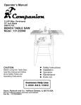
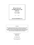
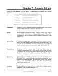
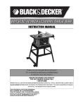
This Manual is Bookmarked
Operating Instructions — Parts Manual
14-Inch Vertical Band Saws
Models: 8201, 8203, 8201VS and 8203VS
WHM TOOL GROUP
2420 Vantage Drive
Elgin, Illinois 60123
Ph.: 800-274-6848
www.wmhtoolgroup.com
Part No. 9078171
Revision C2 04/07
Copyright © 2007 WMH Tool Group
Table of Contents
Cover Page .................................................................................................. 1
General Specifications ................................................................................. 4
Operating Precautions ................................................................................. 5
Set-up and Operation ................................................................................... 7
Wiring Diagrams .......................................................................................... 8
Operating Instructions ................................................................................ 10
Maintenance .............................................................................................. 14
Troubleshooting .......................................................................................... 18
Replacement Parts..................................................................................... 19
3
General Specifications
Wilton’s 14-inch Tradesman Vertical Band Saws
are specially designed to effectively cut a variety of
materials including wood, plastic, bakelite, composites, ferrous and non-ferrous metals. Models
8201 and 8203 are wood and metal cutting band
saws.
Wilton’s Model 8201VS and 8203VS 14-inch
Tradesman Variable Speed Band Saws are ideally
suited for metal cutting only with an infinitely
variable speed range from 116 to 334 SFPM. The
variable speed drive system allows the operator to
fine-tune the blade speed to the material being cut
to maximize the life of today’s bi-metal blades.
These versatile and dependable saws are capable
of contour cutting, straight cutting and re-sawing,
and these band saws can cut delicate curves in
thick or thin stock.
4
Specifications
Capacity
8201
8203
8201VS
Standard .............. 6-in. under guide ..... 6-in. under guide ....... 6-in. under guide ......
With 12-in. Riser .. 12-in. under guide ... 12-in. under guide ..... 12-in. under guide ....
Blade to frame ..... 13.5-in. .................... 13.5-in. ..................... 13.5-in. .....................
Motor
Rating .................. 1 HP 1-Ph ............... 1 HP 3-Ph ................. 1 HP 1-Ph ................
Voltage ................. 115 vac .................... 220/440 vac .............. 115 vac ....................
Speed .................. 1725 rpm ................. 1725 rpm .................. 1725 rpm ..................
Cutting Speeds
Wood (SFPM) ...... 3300 ........................ 3300 ......................... 2600 .........................
Metal (SFPM) ....... 39, 57, 78, 107, ....... 39, 57, 78, 107, ........ 116 – 334 .................
142, 196, 278 .......... 142, 196, 278 ............ Variable Speed .........
Dimensions
Length ................. 20 Inches ................ 20 Inches .................. 20 Inches .................
Width ................... 16 Inches ................ 16 Inches .................. 16 Inches .................
Height .................. 66 Inches ................ 66 Inches .................. 66 Inches .................
Height from Floor ..... 66 Inches ................ 66 Inches .................. 66 Inches .................
Table Tilt to Right ..... 45 Degrees ............. 45 Degrees ............... 45 Degrees ..............
Table Tilt to Left ....... 10 Degrees ............. 10 Degrees ............... 10 Degrees ..............
Miter Gauge Groove
Width ................... 3/4-Inch ................... 3/4-Inch .................... 3/4-Inch ....................
Depth ................... 3/8-Inch ................... 3/8-Inch .................... 3/8-Inch ....................
Miter Gauge ............. Standard .................. Standard ................... Standard ..................
Blade Dimension
Standard .............. 3/8x0.025x92.5 In. ... 3/8x0.025x92.5 In. .... 3/8x0.025x92.5 In. ...
8203VS
6-in. under guide
12-in. under guide
13.5-in.
1 HP 3-Ph
220/440 vac
1725 rpm
2600
116 – 334
Variable Speed
20 Inches
16 Inches
66 Inches
66 Inches
45 Degrees
10 Degrees
3/4-Inch
3/8-Inch
Standard
3/8x0.025x92.5 In.
- Misuse of this machine can cause serious injury.
- For safety, machine must be set up, used and
serviced properly.
- Read, understand and follow instructions in the
Operating Instructions and Parts Manual which
was shipped with your machine.
When Setting up Machine:
- Always avoid using machine in damp or poorly
lighted work areas.
- Always be sure the machine support is securely anchored to the floor or the work bench.
When Using Machine:
- Always wear safety glasses with side shields
(See ANSI Z87.1)
- Never wear loose clothing or jewelry.
- Never overreach - you may slip and fall.
When Servicing Machine:
- Always disconnect the machine from its electrical supply while servicing.
- Always follow instructions in Operating Instructions and Parts Manual when changing accessory tools or parts.
- Never modify the machine without consulting
Wilton Corporation.
You - the Stationary Power Tool User - Hold
the Key to Safety.
Read and follow these simple rules for best results
and full benefits from your machine. Used properly,
Wilton’s machinery is among the best in design and
safety. However, any machine used improperly can
be rendered inefficient and unsafe. It is absolutely
mandatory that those who use our products be
properly trained in how to use them correctly. They
should read and understand the Operating Instructions and Parts Manual as well as all labels affixed to
the machine. Failure to follow all of these warnings
can cause serious injuries.
Machinery General Safety Warnings
1. Always wear protective eye wear when operating machinery. Eye wear shall be impact
resistant, protective safety glasses with side
shields which comply with ANSI Z87.1
specifications. Use of eye wear which does
not comply with ANSI Z87.1 specifications
could result in severe injury from breakage of
eye protection.
2. Wear proper apparel. No loose clothing or
jewelry which can get caught in moving parts.
Rubber soled footwear is recommended for
best footing.
3. Do not overreach. Failure to maintain proper
working position can cause you to fall into the
machine or cause your clothing to get caught
pulling you into the machine.
4. Keep guards in place and in proper working
order. Do not operate the machine with guards
removed.
5. Avoid dangerous working environments. Do
not use stationary machine tools in wet or
damp locations. Keep work areas clean and
well lit.
6. Avoid accidental starts by being sure the start
switch is OFF before plugging in machine.
7. Never leave the machine running while unattended. Machine shall be shut off whenever it
is not in operation.
8. Disconnect electrical power before servicing.
Whenever changing accessories or general
maintenance is done on the machine, electrical power to the machine must be disconnected before work is done.
9. Maintain all machine tools with care. Follow
all maintenance instructions for lubricating and
the changing of accessories. No attempt shall
be made to modify or have makeshift repairs
done to the machine. This not only voids the
warranty but also renders the machine unsafe.
10. Machinery must be anchored to the floor.
11. Secure work. Use clamps or a vise to hold
work, when practical. It is safer than using
your hands and it frees both hands to operate
the machine.
12. Never brush away chips while the machine is
in operation.
13. Keep work area clean. Cluttered areas invite
accidents.
14. Remove adjusting keys and wrenches before
turning machine on.
15. Use the right tool. Don’t force a tool or attachment to do a job it was not designed for.
16. Use only recommended accessories and follow
manufacturers instructions pertaining to them.
17. Keep hands in sight and clear of all moving
parts and cutting surfaces.
18. All visitors should be kept at a safe distance from
the work area. Make the workshop completely
5
safe by using padlocks, master switches, or by
removing starter keys.
19. Know the tool you are using — its application,
limitations, and potential hazards.
General Electrical Cautions
This saw should be grounded in accordance
with the National Electrical Code and local codes
and ordinances. This work should be done by a
qualified electrician. The saw should be grounded
to protect the user from electrical shock.
Wire Sizes
Conductor Length
0 - 50 Feet
50 - 100 Feet
Over 100 Feet
Caution: For circuits which are far away from the
electrical service box, the wire size must be increased in order to deliver ample voltage to the
motor. To minimize power losses and to prevent
motor overheating and burnout, the use of wire sizes
for branch circuits or electrical extension cords
according to the following table is recommended.
AWG (American Wire Gauge) Number
240 Volt Lines
120 Volt Lines
No. 14
No. 14
No. 14
No. 12
No. 12
No. 8
Safety Instructions on Sawing Systems
6
1. Always wear leather gloves when handling saw
blade. The operator shall not wear gloves when
operating the machine.
2. All doors shall be closed, all panels replaced,
andother safety guards in place prior to the
machine being started or operated.
3. Be sure that the blade is not in contact with the
workpiece when the motor is started. The
motor
shall be started and you should
allow the saw to
come up to full speed
before bringing the saw
blade into contact
with the workpiece.
4. Keep hands away from the blade area. See
Figure A.
5. Remove any cut off piece carefully while
keeping your hands free of the blade area.
6. Saw must be stopped and electrical supply
must be cut off before any blade replacement
or adjustment of blade support mechanism is
done, or before any attempt is made to change
the drive belts or before any periodic service or
maintenance is performed on the saw.
7. Remove loose items and unnecessary
workpieces from area before starting machine.
A
B
8. Bring adjustable saw guides and guards as
close as possible to the workpiece.
9. Always wear protective eye wear when
operating, servicing, or adjusting machinery.
Eyewear shall be impact resistant, protective
safety glasses with side shields complying with
ANSI Z87.1 specifications. Use of eye wear
which does not comply with ANSI Z87.1
specifications could result in severe injury
from breakage of eye protection.
See Figure B
10. Nonslip footwear and safety shoes are recommended. See Figure C.
11. Wear ear protectors (plugs or muffs) during
extended periods of operation. See Figure D.
12. The workpiece, or part being sawed, must be
securely clamped before the saw blade enters
the workpiece.
13. Remove cut off pieces carefully, keeping
hands away from saw blade.
14. Saw must be stopped and electrical supply cut
off or machine unplugged before reaching into
cutting area.
15. Avoid contact with coolant, especially guarding
your eyes.
C
D
Introduction
Setup and Operation
This manual includes operating and maintenance
instructions for the Wilton 14-Inch Tradesman
Vertical Band Saws, Models 8201, 8203, 8201VS,
and 8203VS. This manual also includes parts
listings and illustrations of replaceable parts.
Set-up
Band Saw Features
The band saw is shipped with the saw frame
separated from the saw base. Set-up of the band
saw involves installing the frame and setting-up the
saw on the shop floor.
Assembly of Band Saw
Refer to Figures 1 through 3 for key features of the
band saw machine. Refer to the Specifications
section for additional information on the features
and capabilities of the saw.
The saw is shipped as two separate units — saw
frame and base. The saw frame must, therefore,
be assembled to the base.
1. Remove loose parts from the saw base and
sawframe.
2. Place the base in the location in the shop and
bolt the base to the floor. (See following
section on spotting saw.) Put shims under the
hold-down bolts as required to make sure the
saw is level.
3. Place the saw frame on the base. Be sure the
pulleys on the saw frame and pulleys in the
base are aligned with each other.
4. Install the four bolts, upper washers, lower
washers, lock washers and nuts that secure
the frame to the base finger tight. Using a
straight edge, align the pulleys. Then tighten
the four attachment bolt and nuts.
5. Loosen the motor mounting bolts and install
the drive belt(s).
Blade tension adjustment
knob
Figure 1: Band Saw Features (Rear View)
(Models 8201/8203)
Saw Head
Clutch Knob
Gearbox
Oil Level
Gauge
Drive
Motor
Variable Speed
Control
Pivoting
Motor
Mounting
Plate
Upper
wheel ON/OFF
guard switch
Optional rip
fence
Upper drive
wheel
Upper
blade
guide
support
assembly
Lock Knob
Upper blade
guide and
support
assembly
Miter
Table
slot
Blade guard
Lower wheel guard
Dust chute
Lower drive
wheel
Lower blade
guide and
support
assembly
Base
Motor Pulley
Figure 2: Band Saw Features (Rear View)
(Models 8201VS/8203VS)
Figure 3: Band Saw Features (Front View)
(All Models)
7
6. Tension the belts (refer to Changing Drive Belt
Position).
7. Check gearbox fluid level in sight gauge. If
required, add lubricant to bring level halfway up
the sight gauge. (Two containers of Shell
Spirax 90 HD gear oil are packed with the saw.
The containers have sufficient amount of
lubricant to fill the gearbox.)
8. Check blade tension and support mechanism
adjustment (refer to Changing Saw Blades).
9. Plug the motor cable into the switch box on the
saw frame. For 3-phase motors, follow the
instructions in the Electrical section to complete the electrical hookup.
NOTE: Observe all electrical codes. Local codes
or difficult environmental conditions may demand special electrical hook-ups. Always use a
licensed electrician for any special electrical
hook-up.
Setting-up Saw
The saw should be bolted securely to the shop
floor to make sure the saw is stable when sawing
long, heavy or unwieldy work pieces. Always use
extra support for long or heavy stock.
8
There are lugs in the bottom of the saw base for
use in bolting down of the saw. After positioning
the saw, open the door in the base and mark the
positions of the four lug holes. Move the saw to
expose the marks. Prepare for attachment as
required by the attachment method being used.
Install the applicalbe fasteners. Install shims as
required to level the saw. Tighten the fastners to
secure the saw to the floor.
Electrical
2.
3.
4.
5.
6.
7.
8.
the saw before attempting electrical connections.
Connect the green or green-with-white-trace
wire to the branch circuit ground wire.
Connect the remaining three wires to the
power wires in the 3-phase branch circuit.
Reestablish power in the electrical branch.
Turn on power to the saw motor using the
switch.
Observe the direction of the blade. It should
be going DOWNWARD, into the slot on the
table. If it is not going downward, the power
wires are hooked-up incorrectly.
To correct hook-up, disconnect and lock out
power to the branch, again. Reverse any two
of the power wires on the hook-up to the saw
cable.
Reestablish power in the branch and turn the
saw on again. The blade should now be going
downward into the table slot.
Note: local electrical codes or other codes may
require direct connection to a covered, protected
junction box, or other electrical hook-up method.
Especially under difficult industrial conditions,
specialized electrical connections may be
necessary. For special electrical hook-ups, a
licensed electrician should be used to connect
the saw to power.
CAUTION: KNOW AND OBSERVE ALL LOCAL
AND OTHER APPROPRIATE ELECTRICAL
CODES WHEN ATTACHING THIS BAND SAW
TO YOUR POWER SUPPLY.
1-ph.
power
source
Models 8201 and 8201VS are delivered with a 115
volt single phase motor. Models 8203 and 8203VS
are delivered with a 220/440 volt, 3-phase motor.
When the saw is a 115 volt model, it is supplied
with a standard 115 volt plug and power cord which
can be plugged into any suitable branch circuit.
When the saw is equipped with a 3-phase motor
there will be no plug on the 4-wire cable to the saw
switch box. Instead, follow these instructions to
connect the 3-phase motor to the power source:
Connecting to 3-phase power
1. Disconnect and lock out the branch circuit to
Switch
Plug
Motor
Green or green
with white trace
Ground lug
3-ph.
power
source
Switch
Plug
Motor
Green or green
with white trace
Ground lug
Figure 4: Wiring Diagrams
Installing Optional Frame Riser
NOTE: Refer to the illustrations in the Replacement
Parts section for location of the parts used on
the frame riser.
1. Remove the saw blade (refer to Changing Saw
Blades).
2. Remove the two screws at the top and bottom
of the blade guide that holds the blade guide on
the frame.
WARNING: The saw must be turned off and
power disconnected any time the rubber
protectors are being changed.
3. Unplug the electrical cord or open the circuit
breaker in the branch circuit.
4. Support the upper frame and wheel assembly
with a strap attached to an overhead crane.
Use additional straps to be sure the frame
assembly will be held in a stable position when
it is lifted off the lower frame assembly.
5. Remove the nut on the bolt that clamps the
upper frame to the lower frame and remove the
bolt, two washers and nut.
6. Lift the upper frame high enough off of the
lower frame to clear the riser casting.
7. Be certain the mating surfaces of the lower
frame, riser, and upper frame are all clean and
free from dirt and debris.
8. Position the riser casting over the lower frame.
Make sure the locating dowels are inserted in
the mating holes in the riser casting.
9. Lower the upper frame onto the riser casting.
Make sure the locating dowels fit into their
mating holes.
10. Put the new (longer) attaching bolt and top
washer through the upper frame and riser, into
the lower frame.
11. Put a washer and nut on the bolt and tighten
securely.
12. Attach the bracket hooks to the top and bottom
of the blade guard using self-tapping screws.
13. Attach the blade guide using the screws that
held the original (shorter) guard.
14. Remove the old (shorter) blade guide post
assembly from the upper frame.
15. The guide support assembly with the carbide
guides and blade support bearings should be
transferred to the new, longer support rod.
Several other new parts are included for this
component. (Refer to the parts illustrations for
more detail.)
16. Install a new 105-inch blade (refer to Changing
a Blade). Make sure blade tension and tracking
are checked and adjusted as required.
18. Install the extension plug cable between the
motor plug and switch plug.
19. Plug the electrical cord into the power
source or close the circuit breaker on the
branch circuit. Operate the band saw to
verify blade tracking.
Installing Optional Rip Fence
The rip fence slides on two rails attached at the
front and rear of the work table. Install the fence
mechanism as follows:
NOTE: Refer to the illustrations in the Replacement Parts section for location of the parts
used on the rip fence.
1. Slide the rails into the fence.
2. Ease the fence and rails into position on the
table.
3. Using the four spacers and four attachment
bolts, attach the rails securely to the saw
table.
4. The fence can now be adjusted and used
according the instructions in Adjustment and
Use of Optional Rip Fence.
9
Operating Instructions
Operating Controls
START/STOP Switch
The START/STOP switch (refer to Figure 5) is
used to turn on the band saw drive motor. The
START switch has a molded guard which prevent
inadvertent pressing of the START pushbutton.
START/STOP Switch
Guarded START
Switch
E-Stop
Figure 5. START/STOP Controls
The STOP pushbutton is not guarded to allow use
as an E-stop in an emergency.
Variable Speed Control
The variable speed control (refer to Figure 9) is
used to change the speed of the saw blade. Refer
to Adjusting Blade Speed for additional information on the use of the variable speed control.
10
Operating Instructions
Saw blades
The Wilton 14-inch saws accept blades from 1/8inch wide to 3/4-inch wide. The narrower widths
are used for cutting shapes or circles; the wider
widths are used for straight cuts.
For straight cuts, use the widest available saw
blade. A wide blade provides cutting stability, and
allows for more accurate and straighter cuts.
Blade speed effects the efficiency of the cut and
the service life of the blade. Good shop practice
requires that work-hardening materials, such as
stainless steel, require the cut be completed in a
single pass. Otherwise, the effect of stopping the
cut can result in hardening of the cut interface.
Other materials such as wood require higher blade
speeds to prevent fiber tearing. The chart in
Figure 6 provides suggested blade speeds for
various
types of materials. The recommended speeds
should be decreased 30 to 50% when using
carbon steel blades. (The chart provides speeds
that are based on cutting a 4-inch thick work piece
using a bi-metal blade without cutting fluid.)
The following conditions should also be considered:
1. Increase speed 15% for materials 1/4-inch
thick, 12% for 3/4-inch thick, 10% for 1 1/4inch thick, and 5% for 2 1/2-inch thick.
2. Decrease speed 12% when cutting 8-inch thick
material.
To avoid tooth breakage, select a blade-tooth pitch
that will have two or more teeth in contact with the
workpiece at all times.
Different blade materials and tooth geometry (pitch
and set) permit sawing a wide range of common
and exotic materials. Contact your industrial
distributor for recommendations on specialized
blades. Using the corrrect blade can save you
time, trouble, and the possibility of dulling and
pemature discarding of the blade you normally
might use. NOTE: Always use a sharp blade.
SHARP BLADES ARE CHEAP INSURANCE
AGAINST POOR CUTTING EFFICIENCY AND
ACCELERATED MACHINE WEAR.
Material being cut
Speed (SF/M) range
165
Structural steel shapes
160-165
Low carbon steel
115
Medium carbon steel
90-100
High carbon steel
105-135
Cr-moly steel
90-115
Ni-Cr-moly steel
80-140
Chromium steel
105-115
Cr-vanadium steel
40-80
Tool steel
40-70
Stainless steel
80-100
Free machining steel
55-90
Cast iron
55
Copper alloy (CU-Zm)
90
Bronze
40
Al-bronze
40-45
Monel
25-40
Titanium alloy
3000
Aluminum (soft)
3000
Aluminum (T-6+)
3000
Carbon
80-160
Slate
3000
PTFE sheet, rod, rounds
3000
Hard rubber
3000
Plywood
3000
Other woods
Figure 6. Blade Speed to Material Chart
Adjustments
Adjusting Blade Support/Guide Height
The upper blade support and guide mechanism
can be adjusted to accomodate the height of the
work piece.
1. To adjust the support, loosen the knob that
clamps the support rod, then move the support
up or down in its holder. (Refer to Figure
location of the support mechanism.
2. Adjust the support so there is space between
the support and work piece. Space of approximately 1/8-inch is generally appropriate.
Adjusting Blade Tension
Blade tension is set by a spring loaded tension
mechanism on the upper drive wheel. Check the
level of the tension device before cutting. The
tension for various blade widths as indicated on the
casting on the tension device.
Figure 8. Table Tilt Mechanism and Angle Gauge
Adjusting Table Angle
(Refer to Figure 8.) The angle gauge is under the
front of the table. The angle gauge shows the
angle of the table relative to the saw blade. The
table is mounted on trunnions that allow
adjustment downward 45 degrees, and upward 10
degrees. Loosen the two trunnion lock knobs
slightly to adjust the table angle and retighten the
lock knobs.
NOTE: by adjusting the positive leveling stop on
the table leveling mechanism, it is possible to tilt
the table upward 10 degrees. When returning
to 0 degrees, the table leveling mechanism
must be reset after completing the sawing
operation (refer to Machine Set-up).
WARNING: When cutting at an angle with a
tilted table, provide a guide against which
the material being cut can rest. Cutting
“freehand” at an angle, can result in injury
and maintaining an accurate cut is it difficult.
Leveling Work Table
The table can be adjusted to level the table relative
to the saw bleade. Use the following method:
WARNING: The saw must be turned off and
power disconnected any time the gearbox
lubricant is being drained or filled.
Figure 7. Saw Blade Tension and Tracking Mechanism
1. Unplug the electrical cord or open the circuit
11
2.
3.
4.
6.
7.
8.
9.
10.
11.
12
breaker in the branch circuit.
Move the upper blade guide assembly to the
very top of its travel.
Make sure the blade is straight, and fully
tensioned. (A damaged or worn blade may
provide a poor reference surface for squaring
the table.)
Loosen the table lock knobs and hold the
table firmly against its positive leveling stop.
Using a machinist’s square, check to make
sure the table is 90 degrees to the blade.
USING LEATHER PROTECTIVE GLOVES,
turn the upper drive wheel to check the
squareness at a minimum of three points on
the blade
If the table is not level, unlock the lock nut on
the table leveling bolt.
Turn the leveling bolt as required to make the
table square to the blade.
Lock the leveling bolt lock nut and recheck the
table level. When the table is level...
Lock the table lock knobs securely and
recheck for level. Adjust as necessary until
the table is level while everything is tightened
to working tightness.
With everything locked down, look at the
pointer for the angle gauge. It should be
exactly on the zero mark of the gauge (Figure
12). If not, loosen the pointer screw, adjust the
pointer until it is on zero, then tighten the
pointer screw while holding the pointer securely in position on zero.
Adjusting Miter Gauge Slot Parallelism
The miter slot should be parallel to the side of the
blade. If the saw is not cutting straight when using
the miter gauge, the miter slot may not be parallel.
1. Put a straight edge against the blade. Make
sure to position the blade so tooth offset does
not affect the straight edge.
2. Measure from both ends of the miter slot to the
straight edge.3.
If the measurements are
not equal at both ends of the slot, loosen six
bolts securing the table to the table trunnions
(see Figures 12 and 13.)
4. Adjust the table until it is parallel with the blade.
5. Tighten the trunnion attaching bolts.
Adjusting Blade Speed
(Models 8201/8203)
Figure 6 on page 9 provides blade speeds for
various materials. To adjust the blade speed,
change the clutch position of the clutch (in or out)
and the position of the drive belt on the pulleys on
the motor and reduction gearbox shafts.
Adjusting Blade Speed
(Models 8201VS/8203VS)
See Figure 9 at bottom of this page.
1. The blade speed is controlled by an adjustment
mechanism on the right end of the
saw. Speed increases or decreases as the
knob is turned
2. A placard on the drive belt guard (shown
below) provides recommended speeds for
various materials.
3. A speed indicator is provided on the barrel of
the adjustment mechanism. In surface feet per
minute; Position 0 = 334, 1 = 262, 2 = 216, 3 =
171, 4 = 137, and 5 = 116.
4. Turn the speed adjustment knob to the desired
setting as determined by the material being
cut.
Changing Clutch Position
WARNING: NEVER attempt to shift the clutch
mechanism while the saw is running. The
saw must be turned off before clutch shifted.
Speed
Indicator
Variable
Speed
Control
Top View
Front View
Figure 9. Variable Speed Control
1. Turn the main switch to off.
2. Pull the door open on the pulley case.
3. Turn the clutch handle clockwise and push in,
to engage the high speed pulley drive. Or, turn
the clutch handle clockwise, and pull out, to
engage the reduction gearbox drive.
5. Release the weight of motor so the motor
pivots downward. The weight of the motor is
provide adequate belt tension.
6. Plug the electrical cord into the power source
or close the circuit breaker on the branch
circuit.
NOTE: When pushing or pulling the clutch knob,
the dogs on the clutch mechanism are being
engaged. Take the time make sure the clutch
handle is all the way in, or all the way out, so the
clutch dogs are in full engagement when the saw
is started.
4. Close the pulley case door.
5. Plug the electrical cord into the power source or
close the circuit breaker on the branch circuit.
Changing Pulley-to-Belt Position
Changing Drive Belt Position
WARNING: The saw must be turned off and
power disconnected before changing drive
belt positions.
Refer to Figure 9, below.
1. Unplug the electrical cord or open the circuit
breaker in the branch circuit.
2. Open the door on the machine base and the
door on the pulley case.
3. Push up on the motor to pivot the motor
upward and slacken the drive belt.
4. Move the drive belt to the desired pulley
position.
NOTE: Never force the belts to change pulley
location without pivoting the motor to loosen the
motor belt. Failure to do so can cause damage
to the drive mechanism, and accelerate belt
wear and possibly result in belt failure.
WARNING: NEVER attempt to change pulley
shaft positions while the saw is running.
The saw must be turned off and power
disconnected any time pulley shaft poistions
are being changed.
1. Unplug the electrical cord or open the circuit
breaker in the branch circuit.
2. Open the door on the machine base and the
door on the pulley case.
3. Push up on the motor to pivot the motor
upward and slacken the drive belt.
4. With the motor drive belt loose, remove both
pulley drive belts.
5. Both of the pulleys are secured to their shafts
with two set screws. These are located in the
bottoms of the V-grooves on the pulleys.
Using a hex wrench, loosen (but do not
remove) all four set screws.
6. Pull the pulleys straight off each shaft.
7. Put the lower pulley on the upper shaft and the
upper pulley on the lower shaft.
8. Push the upper pulley firmly against the
reduction gearbox and tighten the two set
screws which secure it to the shaft.
9. Using a straight edge against the pulley
flanges, make certain the bottom pulley is
aligned with the upper pulley. Then tighten the
two set screws that secure the lower pulley to
the shaft.
Figure 10. Clutch to Pulley Speed Settings
13
10. Install the belts as required (refer to Figure 10).
11. Release the weight of motor so the motor
pivots downward. The weight of the motor will
provide adequate belt tension.
12. The weight of the motor should provide
sufficient tension so the the middle of the small
drive belt is displaced approximately the
thickness of the belt. (The high speed belt is
adjusted at the same time as the smaller belt.)
13. Set the drive clutch to the desired position (IN
or OUT).
14. Close the access doors.
15. Plug the electrical cord into the power source
or close the circuit breaker on the branch
circuit.
Using Miter System
A miter gauge is provided with the band saw. The
miter gauge slips into a slot in the face of the work
table. The miter gauge can be adjusted from 0 to
45 degrees.
Adjust the miter gauge as follows:
1. Loosen the clamping screw on the miter
gauge.
2. Adjust to desired angle.
3. Tighten the clamping screw.
Using Rip Fence
14
1. Unlock the fence by loosening the lock knob
(ref. 7) and handle (ref. 10.)
2. Slide the fence on its guides until it is the
required distance from the blade.
3. Tighten the lock knob and handle, slightly.
4. Using a machinist’s square, measure the
distance between the edge of the miter slot
and both the front and rear of the rip fence.
Adjust so both distances are equal.
5. Check the fence-to-blade gap, again. Readjust the fence, if necessary, until the blade gap
is correct and the fence is parallel with the
miter slot.
6. Tighten the fence firmly using the lock knob
and handle.
Using the Dust Control Chute
On the lower side of the table, below the cutting
position of the blade, is a plastic tube which can be
attached to a shop vacuum, or to a shop dust
control system. The dust control chute can be seen
in several of the figures used to illustrate the
operation of the saw.
Maintenance
This section contains periodic maintenance
recommendations and maintenance procedures.
Changing Saw Blade
WARNING: The saw must be turned off and
power disconnected any time saw blades
are being changed.
1. Unplug the electrical cord or open the circuit
breaker in the branch circuit.
2. Pull open both upper and lower drive wheel
guards (refer to Figure 1).
3. Release blade tension completely by turning
the tension handle fully counterclockwise.
4. Remove table leveling pin. The pin has a tight
push fit in its slot; it is not threaded. (Refer to
Figure 13.
5. Use a screwdriver to pop out the table insert.
6. Loosen the set screws that lock the guide
blocks. Move the guide blocks outward. Then
turn the micro-adjusting knob to move the
blade support bearing to the very rear of its
travel.
7. Using a hex wrench, loosen the set screw that
locks the lower blade guide and support
assembly. Move the assembly to the very rear
of its travel by using the micro-adjusting knob
on the back side of the assembly (refer to
Figure 11).
Blade support
bearing
Support
bearing
microadjusting
knob
Blade
Guide block
set screws
Guide block
support
microadjusting
knob
Carbide guide blocks
Figure 11. Upper Blade Guides
8. Using a hex wrench, loosen the carbide blade
guide set screws. Open up a reasonably large
gap between the guides; do this on both the
upper and lower blade guides.
9. USING LEATHER GLOVES AND ANSI Z87.1
EYEWEAR TO PROTECT YOURSELF FROM
THE CUTTING BLADE, carefully remove the
blade from the drive wheels. Remove the
blade out of the saw table through the table.
10. Hang the removed blade in a safe place.
Leveling
bolt lock
nut
Table leveling
bolt
Trunnion
Blade
attachment support
bolts
bearing
NOTE: Clean out the interior of the saw with a
shop vacuum. Examine the bearings and other
exposed mechanisms of the saw.
11. Using protective gloves, carefully ease the
replacement blade into the table slot and over
the upper and lower drive wheels.
NOTE: It is possible to install the blade upside
down. Make sure the teeth on the blade are
pointing downward.
NOTE: The blade should be “free standing” at the
cutting throat; the upper and lower blade guides
should not touch the blade at any point. Also,
make sure the blade is in the slot in the blade
guard on the left side of the machine frame.
Refer to Figure 1 to identify the blade guard.
12. Apply tension to the blade using the tension
knob. The tension levels for various blade
widths are shown on the markings on the
tension device. Refer to Figure 3 for a view of
the tension system.
13. Slowly turn the upper drive wheel by hand,
while OBSERVING THE BLADE TRACKING.
The blade should track, more or less, in the
center of the drive wheel. If the blade does not
track true, adjust the tracking to keep the blade
centered.
14. Unlock the tilt adjustment knob by loosening
its locking wing nut. Both the adjustment knob
and wing nut are identified in Figure 7.
15. Turn the tilt adjustment knob (usually a VERY
LITTLE at a time) to adjust the tilt of the upper
drive wheel. Do this while turning the upper
wheel by hand, and adjusting until the blade
stays centered on the wheel.
16. Tighten the tilt mechanism locking wing nut.
17. Using the micro-adjusting knob, move the
lower blade support assembly (Refer to Figure
12) forward until the support bearing just
contacts the back edge of the saw blade.
18. Adjust the lower carbide blade guides until they
just contact the sides of the blade. Make sure
the guides DO NOT CONTACT THE TOOTH
PORTION OF THE BLADE. The guides
should touch only the flat part of the blade.
After correctly positioning the carbide guide
blocks, tighten the set screws securely.
Blade guide
microadjusting
knob
Front
trunnion
lock
knob
Carbide
blade guide
Guide
block
support
Blade support
bearing microadjusting knob
Rear
trunnion
lock
knob
Figure 12. Lower Blade Guide Support
Rear View
Front trunnion
Table leveling
pin
Lower blade
support bearing
Trunnion
attachment
bolt
rear
trunnion
Guide block
microadjusting
knob
Front
trunnion
lock knob
Rear trunnion
lock knob
Carbide guide block
Figure 13. Lower Blade Guide Supports
Front View
19. Adjust the upper support assembly so the
support bearing just contacts the back edge of
the saw blade.
20. Adjust the upper carbide blade guides until they
just make contact with the blade BEHIND THE
TOOTH AREA OF THE BLADE. Then tighten
the set screws securely.
21. Replace the table insert.
22. Insert the table pin into its slot.
23. Close the drive wheel guards.
24. Plug the electrical cord into power source or
close the circuit breaker on the branch circuit.
25. Turn on the power and observe the action of
the blade to sure the blade is correctly adjusted.
15
Draining and refilling the reduction
gearbox.
Blade
WARNING: The saw must be turned off and
power disconnected any time the gearbox
lubricant is being drained or filled.
Blade support bearing
Guide block
set screws
Carbide guide block
Support
bearing
shaft
Guide block
support set
screw
Figure 14. Lower Blade Support Assembly
Replacing drive wheel rubber
protectors
The rubber rings that cover the drive wheels are
called protectors. The protectors protect the wheel
from blade damage and provide a high friction
drive force on the tensioned blade. Over a long
period of service, the protectors wear and may
require replacement.
16
1. Unplug the electrical cord or open the circuit
breaker in the branch circuit.
2. Open the door in the base.
3. Push up on the motor to loosen the drive belts.
4. Remove the pipe plug at the bottom of the
gearbox. Drain the oil into a suitable container
for safe and appropriate disposal.
5. Replace the drain plug.
6. Open the filler plug.
7. Add lubricant until the level is halfway up the
sight gauge window (refer to Figure 15). Use
Shell Spirax HD 90 gear lubricant.
8. Replace the filler plug.
9. Replace the drive belts. Allow the motor to
pivot downward to apply tension to the belts.
10. Close the access door.
11. Plug the electrical cord into the power source
or close the circuit breaker on the branch
circuit.
WARNING: The saw must be turned off and
power disconnected any time the rubber
protectors are being changed.
1. Unplug the electrical cord or open the circuit
breaker in the branch circuit.
2. Remove the blade according to the step-bystep instructions on blade replacement.
3. Remove the rubber protectors from the drive
wheels. Use a flat screwdriver blade or knife
blade to loosen the protectors, being careful
not to nick or score the aluminum drive
wheels.
4. Clean the surface of the drive wheels. Use a
solvent such as mineral spirits as required to
achieve a clean, dry surface for the new
protectors.
5. Carefully slip the replacement protectors onto
the drive wheels.
6. Replace the saw blade and return the saw to
service by following the steps in Changing
Saw Blades.
7. Plug the electrical cord into the power source or
close the circuit breaker on the branch circuit.
Oil Level Gauge
Gear Box Pulley
Figure 15. Gearbox Oil Level Gauge
Periodic Maintenance
Refer to the Periodic Maintenance chart for maintenance that should be performed at various time
intervals.
Troubleshooting
Refer to the Troubleshooting charts for equipment
fault, probable cause and suggested remedy.
Periodic Maintenance
Item
Action
Interval
Maintenance
Saw blade
Listen for sound of
missing teeth
Observe cutting
action for cleanness
and accuracy
Listen for a poor weld
— a “click” as it
passes through the
guide blocks
Watch for signs of
slippage on the drive
wheels (blade occasionally slows or
comes to a stop while
sawing)
Check bearing area
for leakage of lubricant
Check bearing area
for leakage of lubricant
Check for cleanliness
Whenever
operating saw
Whenever
operating saw
Replace blade when teeth are
broken
Replace blade when bent — or worn
— Use a wider blade for more
accurate straight cuts
When changing
blade
Use a different blade or dress the
weld with a grinder.
Whenever
sawing
Be sure you are using the correct
blade tension — Check drive wheel
rubber strips for cleanliness and
adherence to drive wheel — replace if
necessary
Lower drive
wheel
Upper drive
wheel
Drive wheel
rubber protectors
Drive belts
Reduction
gearbox
Monthly
Replace bearing if leakage occurs
Monthly
Replace bearing if leakage occurs
Daily and when
changing blade
Wipe or brush clean
Check for smooth
surfaces and adherence to drive wheel
surface
Monthly or when
blade slippage
occurs
Clean when necessary — replace if
damaged or excessively worn
Check for glazing
Monthly, or when
slippage occurs
(squealing belt)
Replace a glazed belt — DO NOT USE
BELT DRESSING
Check sight glass for
level — should be to
halfway point on sight
glass
Daily
Fill up to half-way point on sight glass
with Shell Spirax HD 90
Annually
Drain and refill with Shell Spirax
HD 90
17
Blade support
bearings
Check for wear,
damage or lubricant
leakage
Monthly and when
changing blade
Replace when necessary
Carbide blade
guides
Check for excessive
wear
When changing
blade
Replace if excessively worn
Troubleshooting
Fault
Probable cause
Suggested remedy
Excessive blade
breakage
1. Material loose in vise.
2. Incorrect speed or feed.
1. Clamp work securely.
2. Refer to Figure 6 or check
Machinist’s Handbook for speed/
feed appropriate for the material
being cut.
3. Check Machinist’s Handbook for
recommended blade type.
4. Adjust blade tension to the point
where the blade just does not slip
on the wheel.
5. Start the motor before placing the
saw on the workpiece.
6. Adjust blade tracking.
7. Adjust guides.
8. Longer annealing cycle.
3. Teeth too coarse for material.
4. Incorrect blade tension.
5. Saw blade contacts workpiece
before the saw is started.
6. Blade rubs on the wheel flange.
7. Misaligned guides.
8. Cracking at weld.
Premature blade
dulling
1. Blade teeth too coarse.
2. Blade speed too high.
3. Hard spots in workpiece or scale
on/in workpiece.
4. Work hardening of material
(especially stainless steel).
5. Insufficient blade tension.
6. Operating saw without pressure
on workpiece.
18
Bad cuts
(out-of-square)
1. Feed pressure too fast.
2. Guide bearings not adjusted
properly.
3. Inadequate blade tension.
4. Dull blade.
5. Incorrect blade speed.
6. Blade guide assembly is loose.
7. Blade guide bearing assembly
loose.
8. Blade track too far away from
wheel flanges.
9. Guide bearing worn.
Bad cuts (rough)
1. Blade speed too high for feed
pressure.
2. Blade is too coarse.
1. Use a finer tooth blade.
2. Try a lower blade speed.
3. Increase feed pressure (hard
spots). Reduce speed, increase
feed pressure (scale).
4. Increase feed pressure by reducing spring tension.
5. Increase tension to proper level.
6. Do not run blade at idle in/on
material.
1. Decrease pressure.
2. Adjust guide bearing clearance to
0.001 inch (0.002 inch maximum).
3. Gradually increase blade tension.
4. Replace blade.
5. Check blade speed
(see Figure 6).
6. Tighten blade guide assembly.
7. Tighten blade guide bearing
assembly.
8. Adjust blade tracking.
9. Replace worn bearing.
1. Reduce blade speed and feed
pressure.
2. Replace with finer blade.
Troubleshooting (Continued)
Blade is twisting
1. Blade is binding in the cut.
2. Blade tension too high.
1. Decrease feed pressure.
2. Decrease tension on blade
Unusual wear on
side/back of blade
1. Blade guides worn
2. Blade guide bearings not
adjusted.
3. Blade guide bearing bracket is
loose.
1. Replace blade guides.
2. Adjust blade guide bearings.
1. Blade tooth pitch too coarse for
workpiece.
2. Feed too slow; feed too fast.
1. Use blade with finer tooth pitch.
Teeth missing/
ripped from blade
3. Tighten blade guide bearing
bracket.
3. Workpiece vibrating.
4. Gullets loading up with chips.
2. Increase feed pressure and/or
blade speed.
3. Clamp workpiece securely.
4a. Use blade with a coarse tooth
pitch—reduce feed pressure.
4b. Brush blade to remove chips.
Motor running too
hot
1.
2.
3.
4.
5.
1.
2.
3.
4.
5.
Excessive speed
reducer noise/
vibration
1. V-belt is too tight.
Blade tension too high.
Drive belt tension too high.
Blade too coarse for workpiece
Blade too fine for workpiece
Speed reducer requires lubrication.
Reduce tension on blade.
Reduce tension on drive belt.
Use blade with fine tooth pitch.
Use blade with coarse tooth pitch.
Check speed reducer.
1. Reset V-belt tension.
19
Replacement Parts
This section provides exploded view illustrations that show the replacement parts for the Wilton Model
8201, 8203, 8201VS, and 8203VS Vertical Band Saws. Also provided are parts listings that provide part
number and description. The numbers shown on the illustration relate to the item number in the facing
parts listing.
Order replacement parts from:
WMH Tool Group
2420 Vantage Drive
Elgin, IL 60123
Phone: 847-274-6848
Identify the replacement part by the part number shown in the parts listing. Be sure to include the model
number and serial number of your machine when ordering replacement parts to assure that you will
receive the correct part.
Exploded View and Parts Listing – Base –
Models 8201, 8203, 8201VS and 8203VS
20
Ref
No.
1
2
3
4
5
Part.
Number
5513834
5513835
5513836
5513837
5513838
6
8
5513839
5784391
5784411
5784421
5784431
5513842
5784281
5513844
5513845
9
10
11
12
13
5513846
Description
Base
Door
Lock (Ref. Note 1)
Washer (Ref. Note 1)
Bolt, Pan Head (M4x5)
(Ref. Note 1)
Pad
Motor - 115V 1-ph
Motor - 220/460V 3-ph
Cord, Motor - 1-ph
Cord, Motor - 3-ph
Strain Relief
Plate, Strain Relief
Case, Pulley
Cover, Pulley Case
(Not Shown)
Knob
Qty
1
1
1
1
2
2
1
1
2
1
1
1
1
Ref
No.
18
19
20
21
22
23
24
25
26
27
28
29
30
31
Part.
Number
5513847
5513848
5513849
5784331
5513851
5782761
5513853
5513854
5513855
5513856
5513857
5513858
5513859
5513860
32 5513861
33* 5507565
Description
Nut (M5)
Nut (M8)
Bolt, Carriage (M8x16)
Bolt, Hex Head (M6x12)
Bolt, Hex Head (M8x25)
Bolt, Pan Head (M5x12)
Washer, Flat (M5x• 10)
Washer, Flat (M6x• 16)
Washer, Flat (M8x• 18)
Washer, Spring (M8)
Nut, Nylon (M8)
Lock Assembly
Key
Stand, Close
(Not Shown)
Bracket, Motor
Base Assembly
without motor
Note 1: Noted parts are part of lock assembly, number 29
* Ref No. 33 includes all components shown in the Exploded View except the motor (Ref No. 8).
Qty
4
8
4
1
4
6
8
1
12
8
2
1
1
1
1
1
Exploded View – Saw Head – Models 8201, 8203, 8201VS, and 8203VS
21
22
Parts Listing – Saw Head – Models 8201, 8203, 8201VS, and 8203VS
Ref
No.
1
2
3
4
5
6
7
8
9
10
11
12
13
14
15
16
17
18
19
20
21
22
23
24
25
26
27
28
29
30
31
32
33
34
35
36
37
38
39
40
Part.
Number
5782511
5782521
5782531
5782541
5782551
5782561
5782571
Description
Upper Arm, Frame
Bracket, Upper Wheel Sliding
Hinge, Upper Wheel Shaft
Pin, Pivot
Shaft, Upper Wheel
Pin, Roll (4x16)
Knob, Blade Track Adjustment
(M8x55)
5782581 Nut, Wing (M8x1.25)
5782591 Knob, Blade Tension Adjstmnt
5782611 Spring, Tension
5782621 Nut, Square
5782631 Guard, Upper Wheel (Inner)
5782641 Screw, Pan Head (M5x0l8x6)
5782651 Washer, Flat (M5x10)
5782661 Wheel, Upper
5782671 Bearing (6202Z)
5782681 Ring, Retaining (R-35)
5782691 Protector, Wheel
5782711 Nut, Hex (M12)
5782722 Blade, Saw, Metal Cutting
(92.5 x 0.025 x 14R)
5782732 Blade, Saw, Wood Cutting
(92.5 x 0.025 x 6H)
5782741 Bolt, Fixed
5782751 Catch
5782761 Screw, Pan Head (M5x0.8x12)
5782771 Bracket
5782781 Bolt, Hex Head (M8x1.25x16)
5782791 Lock, Male
5782811 Screw, Self Tapping (M4x0.7x8)
5782821 Stud
5782831 Guard, Blade
5782841 Retainer
5782851 Screw, Self Tapping (M3.5x12)
5782861 Hinge, Upper
5782871 Screw, Pan Head (M5x0.8x8)
5782881 Nut, Flange (M5x 0.8)
5782891 Guard, Upper Wheel (Outer)
5782911 Washer, Spring (M8)
5782921 Knob (M8x1.25)
5782931 Bracket, Switch
5782941 Screw, Self Tapping (M4x.7x10)
5782951 Switch
Qty
1
1
1
2
1
1
1
Ref
No.
41
42
43
Part.
Number
5782961
5782971
5782981
5513899
44 5782991
5513900
1
1
1
1
1
3
2
1
2
2
2
1
1
45
46
47
48
49
50
51
52
53
54
55
56
57
5783011
5783021
5783031
5783041
5783051
5783061
5783071
5783081
5783091
5783111
5783121
5783131
5783141
1
58
59
60
61
5783151
5783161
5783171
5783181
2
2
2
2
2
4
2
1
2
2
1
12
12
1
1
2
1
2
1
2
5783191
62
63
64
65
66
67
68
69
70
71
72
73
74
75
76
77
5783211
5783221
5783231
------5783241
5783251
5783261
5783271
5783281
5783291
5783311
5783321
5783331
5783341
5783351
Description
Screw, Pan Head (M5x0.8x25)
Strain Relief (6W3-4R)
Cord, Power (110Volt, 1 phase)
Cord, Power (220 Volt, 3 phase)
Cord, Power (Switch to Motor 110 Volt, 1 phase)
Cord, Power (Switch to Motor 220 Volt, 3 phase)
Bushing, Power Cord
Clip, Wire
Screw, Hex Head (M6x1x55)
Base
Bolt, Hex Head (M16x2x55)
Washer, Flat (M16x40)
Nut, Hex (M16)
Hinge (Lower)
Screw, Flat Head (M5x10)
Guard, Lower Wheel
Chute, Dust
Screw, Pan Head (M6x1x8)
Bolt, Hex Head (Left Hand)
(M8x1.25x15)
Washer, Flat
Wheel, Lower
Bearing (6204Z)
Shaft, Lower Wheel
(Metal Cutting Saw)
Shaft, Lower Wheel
(Wood Cutting Saw)
Key (5x5x20)
Bolt, Hex Head (M8x1.25x40)
Washer, Flat (M8x18)
----------Pin, Dowel
Ball, Steel (8 mm)
Spring
Screw, Set (M10x1.5x10)
Knob (M10x1.4x30)
Screw, Pan Head (M6x1x12)
Bearing (6200ZZ)
Sleeve, Upper Spacing
Screw, Set (M6x1x10)
Post, Upper Support Bracket
Post, Guide
Qty
2
1
1
1
1
1
1
1
2
1
1
4
1
1
2
1
1
1
2
1
1
1
4
4
4
----1
1
1
1
2
1
1
7
1
1
2
Ref Part.
No. Number Description
78 5783361 Screw, Micro Adjustment
(M8x1x40)
79 5783371 Nut, Micro Adjustment
80 5783381 Screw, Hex Head (M6x1x10)
81 5783391 Blade Guide, Carbide
82 5783411 Bracket, Support
83 5783421 Guard, Upper Wheel Blade
84 5783431 Washer, Flat (M6x16)
85 5783441 Screw, Hex Head (M6x1x10)
86 5783451 Table
87 5783461 Pin, Roll (3x8)
88 5783471 Insert, Table
89 5783481 Pin, Table
90 5783491 Shoe, Trunnion Clamp
91 5783511 Bolt, Hex Head (M10x50)
92 5783521 Trunnion
93 5783531 Scale
94 5783541 Screw, Hex Head (M6x12)
95 5783551 Screw, Hex Head (M8x80)
96 5783561 Screw, Hex Head (M6x30)
97 5783571 Washer, Lock (M8)
98 5783581 Nut (M8x1.25)
99 5783591 Support, Bracket Trunnion
100 5783611 Pointer
101 5783621 Knob (M10x1.5)
102 5783631 Post, Lower Support Bracket
102 5783641 Block, Adjusting
104 5783651 Plate, Guide
105 5783661 Screw, Flat Head Socket
(M6x1x15)
106 5783671 Sleeve, Spacing
107 - - - -----108 5783681 Bushing, Setting
109 5783691 Screw, Set (M5x0.8x5)
110 5783711 Bar, Adjusting
111 5783721 Handle
112 - - - -----113 5783731 Bar, Adjusting
114 5783741 Washer, Spring (M8)
115 5783751 Nut, Flange (M8)
116 5783761 Washer
117 5783771 Spacer
Qty
2
1
4
2
1
1
2
1
1
1
1
2
2
2
1
6
1
2
2
1
1
1
2
2
1
1
2
2
2
--4
1
2
1
--2
2
2
2
1
Exploded View – Gearbox – Models 8201 and 8203
23
24
Parts Listing – Gearbox – Models 8201 and 8203
Ref
No.
1
2
3
4
5
6
7
8
9
10
11
12
13
14
Part.
Number
5783831
5629151
9100441
5783851
5783861
5783871
5783881
5783891
5783901
5783911
5783921
5783931
5783941
5783951
Description
Housing Gearbox
Bearing (6206ZZ)
Bearing (6200ZZ)
Bearing (6303ZZ)
Plug
Seal, Oil (30x7)
Seal, Oil (17x40x7)
Plug, Drain (1/8x28PT)
Plug (3/8x19PT)
Glass, Oil Level
Gear
Bearing (3206)
Ring, Internal Snap (R62)
Shaft (with gear)
Qty
1
1
3
1
2
1
1
1
1
1
1
1
1
1
Ref
No.
15
16
17
18
19
20
21
22
23
24
25
26
27
28
Part.
Number
5783961
5783971
5783981
5783991
5784011
5513824
5784031
5784041
5784051
5784061
5784071
5784081
5784091
5784111
Description
Key (5x5x18)
Bushing/Spacer
Gear
Shaft (with gear)
Key (5x5x40)
Pin, Parallel (5x20)
Key (7x7x20)
Ring, Retaining (S30)
Seal, Oil
Dog, Clutch
Pin, Roll (5x30)
Shaft, Clutch
Knob
Pulley
Qty
1
1
1
1
1
2
2
3
1
2
2
1
1
1
Ref
No.
29
30
31
32
33
Part.
Number
5784121
5513800
5784141
5784151
5784161
34
5784171
35
36
37
38
39
40
5784181
5784191
5784211
5784221
5784231
5518281
Description
Bushing
Cover, Bearing
Cover, Bearing
Cover, Bearing
Screw, Pan Head
(M5x0.8x8)
Screw, Pan Head
(M6x1x10)
Pulley, Gear Box
Screw, Set (M6x1x10)
V-Belt (A50)
V-Belt (A35)
Pin, Roll (4x16)
Oil, Gear Box 500cc (not
shown)
Qty
1
1
1
1
9
8
1
2
1
1
1
1
Exploded View – Gearbox – Models 8201VS and 8203VS
25
26
Parts Listing – Gearbox – Models 8201VS and 8203VS
Ref
No.
1
2
3
4
5
6
7
8
9
10
11
12
13
14
15
16
17
18
Part.
Number
5513790
5513791
5783861
5783911
5513794
5513795
5513796
5513797
5513798
5783971
5513800
5513801
5784121
5784051
5513804
5513805
5784091
5513807
Description
Housing Gearbox
Packing
Plug
Gauge, Oil Level
Shaft, Lower Wheel
O-Ring (P15)
O-ring (P24)
Block, Clutch
Gear (O)
Spacer
Cover, Bearing (O)
Pulley
Bushing
Seal, Oil (12x22x7)
Rod, Clutch
O-Ring (P9)
Knob (M10)
Gear, Helical (M)
Qty
1
1
2
1
1
1
1
2
1
1
2
1
1
1
1
2
1
1
Ref
No.
19
20
21
22
23
24
25
Part.
Number
5783951
5783871
5784141
5783991
5783881
5784151
5513814
26
5513815
27
28
29
30
31
32
33
5513816
---------9100441
5783851
5783931
Description
Shaft, Gear (M)
Cover, Oil Seal (30x7)
Cover, Bearing (M)
Shaft, Gear (I)
Seal, Oil (17x40x7)
Cover, Bearing (I)
Speed Changer,
Non-Step (Set)
Belt, Synchronous
(V-Type)
V-Belt (A51)
---------------Bearing (6200ZZ)
Bearing (6203ZZ)
Bearing (3206ZZ)
Qty
1
1
1
1
1
1
1
1
1
------3
1
1
Ref
No.
34
35
36
37
38
39
40
41
42
Part.
Number
5629151
5783961
5784011
5784031
5513824
5784071
5783941
5784041
5513828
43
5784161
44
45
5513830
5513831
46
47
5513832
5513833
Description
Bearing (6206ZZ)
Key (5x5x18)
Key (5x5x40)
Key (7x7x20)
Pin, Parallel (5x20)
Pin, Spring (5x30)
Ring, Retaining (R62)
Ring, Stop (S30)
Bolt, Countersunk Head
(M5x10)
Screw, Pan Head (M5x8)
Qty
1
1
1
1
2
2
1
3
3
Bolt, Pan Head (M6x16)
Bolt, Hex Head Socket
(M8x12)
Screw, Set (M6x10)
Plug, Oil
8
1
9
2
1
Parts List – Optional Riser Block – All Models
27
Ref
No.
1
2
3
4
5
6
7
8
9
10
11
12
13
14
15
16
Part.
Number
5784511
5784521
5784531
5784541
5784551
5784561
5784571
5784581
5784591
5784611
5784621
5784631
5782581
5784641
5784681
5784651
5784661
5784671
Description
Block, Riser
Guard, Blade
Hook, Bracket
Screw, Self Tapping
Screw, Hex Head (M16x2x200)
Washer (M16)
Nut (M16)
Post, Guide
Guard, Upper Wheel Blade
Extender, Blade Guard
Bolt, Carriage (M8x15)
Washer (M8)
Nut, Wing (M8)
Blade, Saw (Metal Cutting)
Blade, Saw (Wood Cutting)
Pin, Dowel
Cord, Extension Power (1-Phase)
Cord, Extension Power (3-Phase)
Qty
1
1
2
4
1
1
1
1
1
1
1
1
1
1
1
2
1
1
Parts List – Optional Rip Fence – All Models
28
Ref
No.
1
2
3
4
5
6
7
8
9
10
11
Part.
Number
5784811
5784821
5784831
5784841
5784851
5784861
5784871
5784881
5784891
5784911
5784921
12
13
5784931
5782981
5784941
Description
Rail, Guide
Fence, Rip
Seat Assembly, Clamp
Clamp Rail
Plug (7/8)
Spacer
Knob
Bar, Adjusting
Nut (3/8x16UNC)
Handle
Screw, Socket Head Cap
(M8x30)
Screw, Hex Head (M6x12)
Washer (M6)
Gauge Assembly, Miter
(Not Shown)
Qty
2
1
1
1
4
4
1
1
1
1
4
2
2
1
Notes:
29
WMH Tool Group
2420 Vantage Drive
Elgin, IL 60123
Phone: 847-274-6848