1
MAKING MODERN LIVING POSSIBLE
VLT® 2800
The Quick Guide
Phone: 800.894.0412 - Fax: 888.723.4773 - Web: www.ctiautomation.net - Email: [email protected]
VLT 2800 Quick Guide
1 Quick Guide
1 Quick Guide
1
1.1 Safety
1.1.1 Warnings
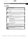
High Voltage Warning:
The voltage of the frequency converter is dangerous whenever it is connected to
mains. Incorrect installation of the motor or frequency converter may cause damage
to the equipment, serious injury or death. Consequently, it is essential to comply
with the instructions in this manual as well as local and national rules and safety
regulations.
Warning:
Touching the electrical parts may be fatal - even after the equipment has been disconnected from mains.Also make sure that other voltage inputs have been disconnected (linkage of DC intermediate circuit). Be aware that there may be high voltage
on the DC link even when the LEDs are turned off. Before touching any potentially
live parts of the frequency converter, wait at least 4 minutes.
Leakage Current:
The earth leakage current from the frequency converter exceeds 3.5 mA. According
to IEC 61800-5-1 a reinforced Protective Earth connection must be ensured by
means of a min. 10mm² Cu or an addtional PE wire - with the same cable cross
section as the Mains wiring - must be terminated separately.
To increase safety, install an RCD
Residual Current Device:
This product can cause a DC current in the protective conductor. Where a residual
current device (RCD) is used for extra protection, only an RCD of Type B (time delayed) shall be used on the supply side of this product. See also Danfoss Application
Note on RCD, MN.90.GX.YY.
Protective earthing of the frequency converter and the use of RCDs must always
follow national and local regulations.
Motor Thermal Protection:
Protection against Motor overload is not included in the factory setting. If this function is required, set par. 128 Motor Thermal Protection to data value ETR trip or data
value ETR warning. For the North American market: The ETR functions provide
overload protection of the motor, class 20, in accordance with NEC.
Installation in high altitudes:
For altitudes above 2 km, please contact Danfoss regarding PELV.
MG.28.M1.02 - VLT® is a registered Danfoss trademark
Phone: 800.894.0412 - Fax: 888.723.4773 - Web: www.ctiautomation.net - Email: [email protected]
1
1 Quick Guide
1
VLT 2800 Quick Guide
1.1.2 Safety Instructions
•
The frequency converter must be disconnected from the mains if repair work is to be
carried out. Check that the mains supply has been disconnected and the prescribed time
has passed before removing motor and mains plugs.
•
Make sure the frequency converter is properly connected to earth.
•
Protect users against supply voltage.
•
Protect the motor against overloading according to national and local regulations.
•
The earth leakage current exceeds 3.5 mA. For ELCB types, please see application note
MN.90.GX.YY.
•
The [STOP/RESET] key on the control panel of the frequency converter does not disconnect the equipment from mains and is thus not to be used as a safety switch.
•
Note that the frequency converter has more voltage inputs than L1, L2 and L3 when DC
bus terminals are used. Check that all voltage inputs are disconnected and that the prescribed time has passed before repair work is commenced.
1.1.3 Warning against unintended start
1.
The motor can be brought to a stop by means of digital commands, bus commands,
references or a local stop, while the frequency converter is connected to mains. If personal safety considerations make it necessary to ensure that no unintended start occurs, these stop functions are not sufficient.
2.
While parameters are being changed, the motor may start. Consequently, the stop key
[STOP/RESET] must always be activated, following which data can be modified.
3.
A motor that has been stopped may start if faults occur in the electronics of the frequency
converter, or if a temporary overload or a fault in the supply mains or the motor connection ceases.
1.1.4 Use on Isolated Mains
See section RFI Switch in the operating instructions regarding use on isolated mains.
It is important to follow the recommendations regarding installation on IT-mains, since sufficient
protection of the complete installation must be observed. Not taking care using relevant monitoring devices for IT-mains may result in damage.
2
MG.28.M1.02 - VLT® is a registered Danfoss trademark
Phone: 800.894.0412 - Fax: 888.723.4773 - Web: www.ctiautomation.net - Email: [email protected]
VLT 2800 Quick Guide
1 Quick Guide
1.2 Introduction
1
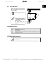
Use this Quick Guide to carry out quick and
EMC-correct installation of the frequency converter in five steps.
Read the safety section before
installing the unit.
NB!
The Operating Instructions, MG.
27.AX.YY, give further examples
of installation and describe all
functions in detail.
The
Design
Guide,
MG.
27.EX.YY, contains extensive information.
1.2.1 Abbreviations
ELCB
NO
NC
PD2
RCD
Earth Leakage Circuit Breakers
Normally open
Normally closed
Dual phase (for 2822, 2840 that only run 3-phase as standard D2), 220 - 240 V
Residual Current Device
1.2.2 Available Litterature
NB!
This quick guide contains only the very basic information necessary for installing and
running the drive.
For more information please consult the VLT 2800 Design Guide, MG.27.EX.YY
MG.28.M1.02 - VLT® is a registered Danfoss trademark
Phone: 800.894.0412 - Fax: 888.723.4773 - Web: www.ctiautomation.net - Email: [email protected]
3
1 Quick Guide
VLT 2800 Quick Guide
Title
1
VLT 2800 Operating Instructions
VLT 2800 Design Guide
VLT 2800 Data Sheet
Mounting Instruction for VLT 2800
VLT 2800 Filter Instruction
Precise Stop
Cold Plate
VLT 2800 NEMA 1 Terminal Covering
VLT 2800 DeviceNet Cable
VLT 2800 Blue Star Condensing Unit
VLT 2880 - 2882 Spare Part Instruction
Wobble Function
VLT 2800 LCP Remote-mounting Kit
User Instruction for LOP
Brake Resistor
Profibus DP Manual
VLT 2800 DeviceNet Manual
Metasys N2 Manual
Profibus Manual
Output Filter Manual
Brake Resistor Manual
MCT-10 Manual
Modbus RTU Manual
Protection against Electrical Hazards
Literature no.
MG.27.AX.YY
MG.27.EX.YY
MD.27.AX.YY
MI.28.AX.YY
MI.28.BX.YY
MI.28.CX.YY
MI.28.DX.YY
MI.28.EX.YY
MI.28.FX.YY
MI.28.GX.YY
MI.28.HX.YY
MI.28.JX.YY
MI.56.AX.YY
MI.90.EX.YY
MI.90.FX.YY
MG.90.AX.YY
MG.90.BX.YY
MG.90.CX.YY
MG.90.EX.YY
MG.90.NX.YY
MG.90.OX.YY
MG.10.RX.YY
MG.10.SX.YY
MN.90.GX.YY
X = Revision Number, Y = Language code
Application notes can be found on Danfoss website under BusinessAreas/DrivesSolutions/Documentations/Technical+Documentation.htm
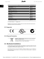
1.2.3 Approvals
1.2.4 Disposal Instruction
Equipment containing electrical components must not be disposed of
together with domestic waste.
It must be separately collected with electrical and electronic waste
according to local and currently valid legislation.
1.3 Mechanical Installation
VLT 2800 frequency converters allow side-by-side installation on a wall in any position as the units
do not require ventilation on the side. Because of the need for cooling, there must be 10 cm free
air passage above and below the frequency converter.
All units with enclosure IP 20 must be integrated in cabinets and panels. IP 20 is not suitable for
remote mounting. In some countries, e.g. in the USA, units with enclosure NEMA 1 are approved
for remote mounting.
4
MG.28.M1.02 - VLT® is a registered Danfoss trademark
Phone: 800.894.0412 - Fax: 888.723.4773 - Web: www.ctiautomation.net - Email: [email protected]
VLT 2800 Quick Guide
1 Quick Guide
NB!
With the IP 21 solution all units require a minimum of 100 mm air on each side. This
means that side-by-side mounting is NOT allowed.
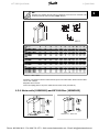
Size mm
S2
VLT 2803 - 2815
D2
VLT 2803 - 2815
VLT 2822*
VLT 2840*
PD2
VLT 2822
VLT 2840
T2
VLT 2822
VLT 2840
T4
VLT 2805 - 2815
VLT 2822 - 2840
VLT 2855 - 2875
VLT 2880 - 2882
A
a
B
b
C
D
E
øa
øb
F
øc
200
191
75
60
168
7
5
4.5
8
4
4.5
200
267.5
267.5
191
257
257
75
90
140
60
70
120
168
168
168
7
8
8
5
6
6
4.5
5.5
5.5
8
11
11
4
4.5
4.5
4.5
5.5
5.5
267.5
505
257
490
140
200
120
120
168
244
8
7.75
6
7.25
5.5
6.5
11
13
4.5
8
5.5
6.5
267.5
267.5
257
257
90
140
70
120
168
168
8
8
6
6
5.5
5.5
11
11
4.5
4.5
5.5
5.5
200
267.5
267.5
505
191
257
257
490
75
90
140
200
60
70
120
120
168
168
168
244
7
8
8
7.75
5
6
6
7.25
4.5
5.5
5.5
6.5
8
11
11
13
4
4.5
4.5
8
4.5
5.5
5.5
6.5
1
Table 1.1: * Only 3-phase
Drill holes in accordance with the measurements given in the above table. Please note the difference in unit voltages.
Retighten all four screws.
Fit the decoupling plate to the power cables and the earth screw (terminal 95).
1.3.1 Motor coils (195N3110) and RFI 1B filter (195N3103)
Illustration 1.1: Motor coils
MG.28.M1.02 - VLT® is a registered Danfoss trademark
Phone: 800.894.0412 - Fax: 888.723.4773 - Web: www.ctiautomation.net - Email: [email protected]
5
1 Quick Guide
1
VLT 2800 Quick Guide
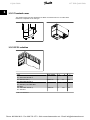
1.3.2 Terminal cover
The drawing below gives the dimensions for NEMA 1 terminal covers for VLT 2803-2875.
Dimension 'a' depends on the unit type.
1.3.3 IP 21 solution
Type
VLT 2803-2815 200-240 V,
VLT 2805-2815 380-480 V
VLT 2822 200-240 V,
VLT 2822-2840 380-480 V
VLT 2840 200-240 V,
VLT 2822 PD2, TR1 2855-2875
380-480 V
TR1 2880-2882 380-480 V,
VLT 2840 PD2
Code number
195N2118
47
A
80
B
C
170
195N2119
47
95
170
195N2120
47
145
170
195N2126
47
205
245
Table 1.2: Dimensions
6
MG.28.M1.02 - VLT® is a registered Danfoss trademark
Phone: 800.894.0412 - Fax: 888.723.4773 - Web: www.ctiautomation.net - Email: [email protected]
VLT 2800 Quick Guide
1 Quick Guide
1
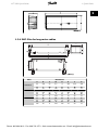
1.3.4 EMC filter for long motor cables
Filter
192HA719
192H4720
192H4893
A
20
B
204
C
20
Dimensions
øa
D
5.5
8
E
234
F
27.5
G
244
H
75
A
20
H
90
A
20
H
140
I
45
B
273
I
50
B
273
I
50
øb
6
C
20
øb
6
C
20
øb
6
J
190
øa
5.5
J
257
øa
5.5
J
257
L
16
E
303
L
16
E
303
L
16
M
24
F
25
M
24
F
25
M
24
N
12
G
313
N
12
G
313
N
12
K
60
D
8
K
70
D
8
K
120
MG.28.M1.02 - VLT® is a registered Danfoss trademark
Phone: 800.894.0412 - Fax: 888.723.4773 - Web: www.ctiautomation.net - Email: [email protected]
7
1 Quick Guide
1
VLT 2800 Quick Guide
1.4 Electrical Installation
1.4.1 Electrical Installation in General
NB!
All cabling must comply with national and local regulations on cable cross-sections
and ambient temperature. Copper conductors required, (60-75° C) recommended.
Details of terminal tightening torques.
VLT
2803 - 2875
2880 - 2882,
2840 PD2
Terminals
Power mains brake
Earth
Power mains brake
Earth
Torque (Nm)
0.5 - 0.6
2-3
1.2 - 1.5
2-3
Torque, Control Cables (Nm)
0.22 - 0.25
Table 1.3: Tightening of terminals.
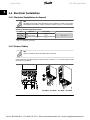
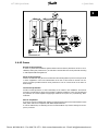
1.4.2 Power Cables
NB!
Please note that the power terminals can be removed.
Connect mains to the mains terminals of the frequency converter, i.e. L1, L2 and L3 and the earth
connection to terminal 95.
VLT 2803 - VLT 2815
8
VLT 2822 - VLT 2840
MG.28.M1.02 - VLT® is a registered Danfoss trademark
Phone: 800.894.0412 - Fax: 888.723.4773 - Web: www.ctiautomation.net - Email: [email protected]
VLT 2800 Quick Guide
1 Quick Guide
1
VLT 2880 - VLT
2882
Fit screened/armoured cable from the motor to the motor terminals of the frequency converter,
i.e. U, V, W. The screen ends in a screen connector.
1.4.3 Mains connection
NB!
Please note that at 1 x 220-240 Volt the neutral wire must be attached to terminal
N (L2) and the phase wire must be connected to terminal L1 (L1).
No.
No.
No.
No.
No.
No.
N(L2)
N
95
L1(L1)
L1
N(L2)
L2
95
L1(L1)
L1
91
L1
95
(L3)
Mains voltage 1 x 220-240 V
Earth connection
(L3)
Mains voltage 3 x 220-240 V
L3
Earth connection
92
L2
93
L3
Mains voltage 3 x 380-480 V
Earth connection
NB!
Please check that the mains voltage fits the mains voltage of the frequency converter, which can be seen from the nameplate.
400-Volt units with RFI-filters may not be connected to mains supplies in which the
voltage between phase and earth is more than 300 Volts. Please note that for the
IT mains and the delta earth the mains voltage can exceed 300 Volts between phase
and earth. Units with type code R5 (IT mains) can be connected to mains supplies
with up to 400 V between phase and earth.
See Technical data for correct dimensioning of cable cross-section. See also the section entitled
Galvanic isolation in the Operating Instructions for further details.
MG.28.M1.02 - VLT® is a registered Danfoss trademark
Phone: 800.894.0412 - Fax: 888.723.4773 - Web: www.ctiautomation.net - Email: [email protected]
9
1 Quick Guide
1
VLT 2800 Quick Guide
1.4.4 Motor connection
Connect the motor to terminals 96, 97, 98. Connect earth to terminal 99.
See Technical data for correct dimensioning of cable cross-section.
All types of three-phase asynchronous standard motors can be connected to a frequency converter. Normally, small motors are star-connected (230/400 V, Δ/ Y).
NB!
In motors without phase insulation paper, an LC filter should be fitted on the output
of the frequency converter.
The factory setting is for clockwise rotation.
The direction of rotation can be changed by switching two phases on the motor terminals.
1.4.5 Parallel connection of motors
The frequency converter is able to control several motors connected in parallel.
Please consult the Operating Instructions for further information.
NB!
Be aware that the total cable length, listed in the section EMC Emission.
NB!
Parameter 107 Automatic motor adaption, AMT cannot be used when motors are
connected in parallel. Parameter 101 Torque characteristic must be set to Special
motor characteristics [8] when motors are connected in parallel.
10
MG.28.M1.02 - VLT® is a registered Danfoss trademark
Phone: 800.894.0412 - Fax: 888.723.4773 - Web: www.ctiautomation.net - Email: [email protected]
VLT 2800 Quick Guide
1 Quick Guide
1.4.6 Motor Cables
See General Specifications for correct dimensioning of motor cable cross-section and length. See
EMC Emissions for relationship between length and EMC emission.
Always comply with national and local regulations on cable cross-section.
1
NB!
If an unscreened/unarmoured cable is used, some EMC requirements are not complied with, see EMC test results in the Design Guide.
If the EMC specifications regarding emission are to be complied with, the motor cable must be
screened/armoured, unless otherwise stated for the RFI filter in question. It is important to keep
the motor cable as short as possible so as to reduce the noise level and leakage currents to a
minimum. The motor cable screen must be connected to the metal cabinet of the frequency converter and to the metal cabinet of the motor. The screen connections are to be made with the
biggest possible surface area (cable clamp). This is enabled by different installation devices in
different frequency converters. Mounting with twisted screen ends (pigtails) is to be avoided, since
these spoil the screening effect at high frequencies. If it is necessary to break the screen to install
a motor isolator or motor relay, the screen must be continued at the lowest possible HF impedance.
1.4.7 Motor Thermal Protection
The electronic thermal relay in UL-approved frequency converters has received the UL-approval
for single motor protection, when parameter 128 Motor thermal protection has been set for ETR
Trip and parameter 105 Motor current, IM, N has been programmed to the rated motor current
(see motor nameplate).
1.4.8 Control Cables
Remove the front cover underneath the control panel. Place a jumper between terminals 12 and
27.
Control cables must be screened/armoured. The screen must be connected to the frequency converter chassis by means of a clamp. Normally, the screen must also be connected to the chassis
of the controlling unit (use the instructions for the unit in question). In connection with very long
control cables and analogue signals, in rare cases depending on the installation, 50/60 Hz earth
loops may occur because of noise transmitted from mains supply cables. In this connection, it may
be necessary to break the screen and possibly insert a 100 nF capacitor between the screen and
the chassis.
See section entitled Earthing of screened/armoured control cables in the VLT 2800 Design Guide
for the correct termination of control cables.
MG.28.M1.02 - VLT® is a registered Danfoss trademark
Phone: 800.894.0412 - Fax: 888.723.4773 - Web: www.ctiautomation.net - Email: [email protected]
11
1 Quick Guide
VLT 2800 Quick Guide
1
No.
01-03
12
18-33
20, 55
42
461
50
53
60
671
68, 691
701
Function
Relay outputs 01-03 can be used for indicating status and alarms/warnings.
24 V DC voltage supply.
Digital inputs.
Common frame for input and output terminals.
Analog output for displaying frequency, reference, current or torque.
Digital output for displaying status, warnings or alarms, as well as frequency output.
+10 V DC supply voltage for potentiometer or thermistor.
Analogue voltage input 0 - 10 V DC.
Analogue current input 0/4 - 20 mA.
+ 5 V DC supply voltage to Profibus.
RS 485, Serial communication.
Frame for terminals 67, 68 and 69. Normally this terminal is not to be used.
1. The terminals are not valid for DeviceNet/CANopen. See also the DeviceNet manual, MG.
90.BX.YY for further details.
See parameter 323 Relay output for programming of relay output.
01
01
Nr.
-
02
03
1 - 2 make (NO)
1 - 3 break (NC)
NB!
Please note that the cable jacket for the relay must cover the first row of control
card terminals - otherwise the galvanic isolation (PELV) cannot be maintained. Max.
cable diameter: 4 mm.
1.4.9 Earthing
Comply with the following at installation:
12
•
Safety earthing: The drive has a high leakage current and must be earthed properly for
safety. Follow all local safety regulations.
•
High frequency earthing: Keep earthing connections as short as possible.
MG.28.M1.02 - VLT® is a registered Danfoss trademark
Phone: 800.894.0412 - Fax: 888.723.4773 - Web: www.ctiautomation.net - Email: [email protected]
VLT 2800 Quick Guide
1 Quick Guide
Connect all earthing systems to ensure the lowest possible conductor impedance. The lowest
possible conductor impedance is achieved by keeping the conductor as short as possible and by
grounding with the greatest possible surface area. If multiple drives are installed in a cabinet, the
cabinet backplate, which must be made of metal, should be used as a joint earth reference plate.
The drives must be fitted to the backplate at the lowest possible impedance.
1
To achieve low impedance, connect the drive to the backplate with the drive fastening bolts. The
backplate must be completely free from paint.
1.4.10 EMC emission
The following system results are achieved on a system consisting of a VLT Series 2800 with
screened/armoured control cable, control box with potentiometer, screened/armoured motor cable and screened/armoured brake cable as well as an LCP2 with cable.
VLT 2803-2875
Emission
Residential, commercial and light industry
EN 55011 class 1A
EN 55011 class 1B
Cable-borne
Radiated
Cable-borne
Radiated
150 kHz- 30 MHz
30 MHz - 1 GHz
150 kHz - 30 MHz
30 MHz - 1 GHz
Industrial environment
Setup
3 x 480 V version with
1A RFI filter
3 x 480 V version with
1A RFI filter (R5: For
IT mains)
1 x 200 V version with
1A RFI filter 1.
3 x 200 V version with
1A RFI filter (R4: For
use with RCD)
3 x 480 V version with
1A+1B RFI filter
1 x 200 V version with
1A+1B RFI filter 1.
VLT 2880-2882
Setup
3 x 480 V version with
1B RFI filter
Yes
Yes
No
No
25 m screened/
25 m screened/
armoured
armoured
Yes
Yes
No
No
5 m screened/ 5 m screened/armarmoured
oured
Yes
Yes
Yes
No
40 m screened/
40 m screened/
15 m screened/
armoured
armoured
armoured
Yes
Yes
Yes
No
20 m screened/
20 m screened/ 7 m screened/armarmoured
armoured
oured
Yes
Yes
Yes
No
50 m screened/
50 m screened/
25 m screened/
armoured
armoured
armoured
Yes
Yes
Yes
No
100 m screened/ 100 m screened/
40 m screened/
armoured
armoured
armoured
Emission
Industrial environment
Residential, commerce and light industry
EN 55011 class 1A
EN 55011 class 1B
Cable-borne
Radiated
Cable-borne
Radiated
150 kHz- 30 MHz
30 MHz - 1 GHz
150 kHz - 30 MHz
30 MHz - 1 GHz
Yes
50 m
Yes
50 m
Yes
50 m
No
1.
For VLT 2822-2840 3 x 200-240 V the same values apply as for the 480 V version with
1A RFI filter.
•
EN 55011: Emission
Limits and methods of measurement of radio disturbance characteristics of industrial,
scientific and medical (ISM) high-frequency equipment.
Class 1A:
Equipment used in an industrial environment.
Class 1B:
Equipment used in areas with a public supply network (residential, commerce and light industry).
MG.28.M1.02 - VLT® is a registered Danfoss trademark
Phone: 800.894.0412 - Fax: 888.723.4773 - Web: www.ctiautomation.net - Email: [email protected]
13
1 Quick Guide
1
VLT 2800 Quick Guide
1.4.11 Extra protection
RCD relays/ELCBs, multiple protective earthing or earthing can be used as extra protection, provided that local safety regulations are complied with.
Three phase VLT frequency converters require an RCD type B. If an RFI filter is mounted in the
drive and either the switch of the RCD or a manually operated switch is used to connect the drive
to the mains voltage, a time delay of minimum 40 ms is required (RCD type B).
If no RFI filter is mounted of a CI contactor is used for mains connection, no time delay is required.
Single phase VLT frequency converters require an RCD type A. There is no particular need for a
time delay whether RFI filters are mounted or not.
See application note MN.90.GX.YY for further information on ELCBs.
1.4.12 EMC-correct electrical installation
General points to be observed to ensure EMC-correct electrical installation.
-
Use only screened/armoured motor cables and screened/armoured control cables.
-
Connect the screen to earth at both ends.
-
Avoid installation with twisted screen ends (pigtails), since this ruins the screening effect
at high frequencies. Use cable clamps instead.
-
It is important to ensure good electrical contact from the installation plate through the
installation screws to the metal cabinet of the frequency converter.
-
Use starwashers and galvanically conductive installation plates.
-
Do not use unscreened/unarmoured motor cables in the installation cabinets.
The illustration below shows EMC-correct electrical installation, in which the frequency converter
has been fitted in an installation cabinet and connected to a PLC.
14
MG.28.M1.02 - VLT® is a registered Danfoss trademark
Phone: 800.894.0412 - Fax: 888.723.4773 - Web: www.ctiautomation.net - Email: [email protected]
VLT 2800 Quick Guide
1 Quick Guide
1
1.4.13 Fuses
Branch circuit protection:
In order to protect the installation against electrical and fire hazard, all branch circuits in an installation, switch gear, machines etc., must be short-circuited and overcurrent protected according
to national/international regulations.
Short circuit protection:
Danfoss recommends using the fuses mentioned in the following table to protect service personnel
or other equipment in case of an internal failure in the unit or short-circuit on DC-link. The frequency converter provides full short circuit protection in case of a short-circuit on the motor or
brake output.
Overcurrent protection:
Provide overload protection to avoid overheating of the cables in the installation. Overcurrent
protection must always be carried out according to national regulations. Fuses must be designed
for protection in a circuit capable of supplying a maximum of 100,000 Arms (symmetrical), 480 V
maximum.
Non UL compliance:
If UL/cUL is not to be complied with, Danfoss recommends using the fuses mentioned in the below
table, which will ensure compliance with EN50178/IEC61800-5-1:
In case of malfunction, not following the fuse recommendation may result in damage to the frequency converter.
MG.28.M1.02 - VLT® is a registered Danfoss trademark
Phone: 800.894.0412 - Fax: 888.723.4773 - Web: www.ctiautomation.net - Email: [email protected]
15
1 Quick Guide
VLT 2800 Quick Guide
Alternative fuses 380-500 V drives
VLT
BussBussBuss2800
mann
mann
mann
E52273 E4273
E4273
1
RK1/
JDDZ
KTS-R20
J/JDDZ
Bussmann
E4273
T/JDDZ
2805JKS-20
JJS-20
2820
2855KTS-R25
JKS-25
JJS-25
2875
2880KTS-R50
JKS-50
JJS-50
2882
Alternative Fuses 200-240 V drives
2803KTN-R20
JKS-20
JJN-20
2822
2840
KTN-R25
JKS-25
JJN-25
Bussmann
E4273
Bussmann
E4273
SIBA
E18027
6
Little
FerrazFuse
ShawE81895 mut
E16326
7/E2137
FerrazShawmut
E16326
7/
E2137
CC/JDDZ CC/JDDZ CC/JDDZ
RK1/
RK1/
CC/JDDZ
RK1/
JDDZ
JDDZ
JDDZ
FNQKTK-R-20 LP-CC-20 5017906- KLS-R20 ATM-R25 A6K-20R
R-20
020
5017906- KLS-R25 ATM-R20 A6K-25R
025
5014006- KLS-R50
A6K-50R
050
5017906- KLS-R20 ATM-R25 A6K-20R
020
5017906- KLS-R25 ATM-R20 A6K-25R
025
Table 1.4: Prefuses for UL application /cUL
1.4.14 RFI switch
Mains supply isolated from earth:
If the frequency converter is supplied from an isolated mains source ( IT mains) or TT/TN-S mains
with grounded leg, the RFI switch is recommended to be turned off (OFF). For further reference,
see IEC 364-3. In case optimum EMC performance is needed, parallel motors are connected or
the motor cable length is above 25 m, it is recommended to set the switch in ON position.
In OFF position, the internal RFI capacities (filter capacitors) between the chassis and the intermediate circuit are cut off to avoid damage to the intermediate circuit and to reduce the earth
capacity currents (according to IEC 61800-3).
Please also refer to the application note VLT on IT mains, MN.90.CX.02. It is important to use
isolation monitors that are capable for use together with power electronics (IEC 61557-8).
NB!
The RFI switch is not to be operated with mains connected to the unit. Check that
the mains supply has been disconnected before operating the RFI switch.
The RFI switch disconnects the capacitors galvanically from ground.
The switch Mk9, placed next to terminal 96, should be removed to disconnect the RFI-filter.
The RFI switch is only available on VLT 2880-2882.
16
MG.28.M1.02 - VLT® is a registered Danfoss trademark
Phone: 800.894.0412 - Fax: 888.723.4773 - Web: www.ctiautomation.net - Email: [email protected]
VLT 2800 Quick Guide
1 Quick Guide
1
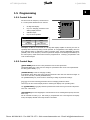
1.5 Programming
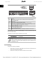
1.5.1 Control Unit
On the front of the frequency converter there
is a control panel divided into four sections.
1.
Six-digit LED display.
2.
Keys for changing parameters and
shifting display function.
3.
Indicator lamps.
4.
Keys for local operation.
LED indication
Warning
Alarm
Trip locked
yellow
red
yellow and red
All displays of data are in the form of a six-digit LED display capable of showing one item of
operating data continuously during normal operation. As a supplement to the display, there are
three indicator lamps for indication of mains connection (ON), warning (WARNING) and alarm
(ALARM). Most of the frequency converter's parameter Setups can be changed immediately via
the control panel, unless this function has been programmed as Locked [1] via parameter 018
Lock for data changes.
1.5.2 Control Keys
[QUICK MENU] allows access to the parameters used for the Quick menu.
The[QUICK MENU] key is also used if a change to a parameter value is not to be implemented.
See also [QUICK MENU] + [+].
[CHANGE DATA] is used for changing a setting.
If the display shows three dots at the right, the parameter value has more than three digits. In
order to see the value, activate [CHANGE DATA]
The [CHANGE DATA] key is also used for confirming a change of parameter settings.
[+] / [-] are used for selecting parameters and for changing parameter values.
These keys are also used in Display mode for selecting the display of an operating value.
The [QUICK MENU] + [+] keys must be pressed at the same time to give access to all parameters. See Menu mode.
[STOP/RESET] is used for stopping the connected motor or for resetting the frequency converter
after a trip.
Can be selected as Active [1] or Not active [0] via parameter 014 Local stop/reset. In Display
mode, the display will flash if the stop function is activated.
MG.28.M1.02 - VLT® is a registered Danfoss trademark
Phone: 800.894.0412 - Fax: 888.723.4773 - Web: www.ctiautomation.net - Email: [email protected]
17
1 Quick Guide
VLT 2800 Quick Guide
NB!
If the [STOP/RESET] key is set at Not active [0] in parameter 014 Local stop/reset, and there is no stop command via the digital inputs or serial communication,
the motor can only be stopped by disconnecting the mains voltage to the frequency
converter.
1
[START] is used for starting the frequency converter. It is always active, but the [START] key
cannot override a stop command.
1.5.3 Manual initialisation
Disconnect mains voltage. Hold the [QUICK MENU] + [+] + [CHANGE DATA] keys down while
simultaneously reconnecting the mains voltage. Release the keys; the frequency converter has
now been programmed for the factory setting.
1.5.4 Display Readout States
In normal operation, one item of operating data can be displayed continuously at the operator's
own choice. By means of the [+/-] keys the following options can be selected in Display mode:
•
Output frequency [Hz]
•
Output current [A]
•
Output voltage [V]
•
Intermediate circuit voltage [V]
•
Output power [kW]
•
Scaled output frequency fout x p008
1.5.5 Menu mode
In order to enter the Menu mode [QUICK MENU] + [+] must be activated at the same time.
In Menu mode, most of the frequency converter parameters can be changed. Scroll through the
parameters using the [+/-] keys. While scrolling in the Menu mode proceeds, the parameter
number will flash.
1.5.6 Quick menu
Using the [QUICK MENU] key, it is possible to access the 12 most important parameters of the
frequency converter. After programming, the frequency converter is in most cases ready for operation. When the [QUICK MENU] key is activated in Display mode, the Quick menu starts. Scroll
through the quick menu using the [+/-] keys and change the data values by first pressing
[CHANGE DATA] and then changing the parameter value with the [+/-] keys.
The Quick menu parameters are shown in section Parameter Lists.
18
MG.28.M1.02 - VLT® is a registered Danfoss trademark
Phone: 800.894.0412 - Fax: 888.723.4773 - Web: www.ctiautomation.net - Email: [email protected]
VLT 2800 Quick Guide
1 Quick Guide
1.5.7 Hand Auto
During normal operation the frequency converter is in Auto mode, where the reference signal is
given externally, analog or digital via the control terminals. However, in Hand mode, it is possible
to give the reference signal locally via the control panel.
1
On the control terminals, the following control signals will remain active when Hand mode is activated:
Hand Start (LCP2)
Off Stop (LCP2)
Auto Start (LCP2)
Reset
Coasting Stop Inverse
Reset and Coasting Stop Inverse
Quick Stop Inverse
Stop Inverse
Reversing
DC Braking Inverse
Setup Select LSB
Setup Select MSB
Thermistor
Precise Stop Inverse
Precise Stop/Start
Jog
Stop Comm. Via Serial Comm.
Switching between Auto- and Hand mode:
By activating the [Change Data] key in [Display Mode], the display will indicate the mode of the
frequency converter.
Scroll up/down in order to switch to Hand mode, the reference can be changed by using [+]/[-].
NB!
Please note, that parameter 020 may block the choice of mode.
A change of parameter values is saved automatically after a mains failure.
If the display shows three dots at the right, the parameter value has more than three digits. In
order to see the value, activate [CHANGE DATA].
Press [QUICK MENU]:
Set the motor nameplate parameters
Motor
Motor
Motor
Motor
Rated
power [kW]
voltage [V]
frequency [Hz]
current [A]
motor speed
Parameter
Parameter
Parameter
Parameter
Parameter
102
103
104
105
106
Activate AMT
Automatice motor tuning Parameter 107
1.
In parameter 107 Automatic motor tuning select data value [2]. “107” will now flash, and
“2” will not flash.
2.
AMT is activated by pressing start. “107” will now flash and dashes will move from left
to right in the data value field.
3.
When “107” appears once more with the data value [0], AMT is complete. Press [STOP/
RESET] to save the motor data.
4.
“107” will then continue to flash with the data value [0]. You can now proceed.
MG.28.M1.02 - VLT® is a registered Danfoss trademark
Phone: 800.894.0412 - Fax: 888.723.4773 - Web: www.ctiautomation.net - Email: [email protected]
19
1 Quick Guide
1
VLT 2800 Quick Guide
NB!
VLT 2880-2882 do not have the AMT function.
Set reference range
Min. reference, RefMIN Parameter 204
Max. reference, RefMAX Parameter 205
Set ramp time
Ramp-up time [s]
Parameter 207
Ramp-down time [s] Parameter 208
In parameter 002, Local/remote control, the frequency converter mode can be selected as Remote
operation [0], i.e. via the control terminals, or Local [1], i.e. via the control unit.
Set the control location to Local [1]
Local/remote operation = Local [1], Par. 002
Set the motor speed by adjusting the
Local reference
Local reference, Par. 003
1.6 Motor Start
Press [START] to start the motor. Set the motor speed by adjusting par. 003, Local reference.
Check whether the direction of rotation of the motor shaft is clockwise. If not, exchange any two
phases on the motor cable.
Press [STOP/RESET] to stop the motor.
Press [QUICK MENU] to return to display mode.
[QUICK MENU] + [+] keys must be pressed simultaneously to give access to all parameters.
20
MG.28.M1.02 - VLT® is a registered Danfoss trademark
Phone: 800.894.0412 - Fax: 888.723.4773 - Web: www.ctiautomation.net - Email: [email protected]
VLT 2800 Quick Guide
1 Quick Guide
1.7 Connection Examples
1
More examples can be found in the Operating Instructions (MG.27.AX.YY).
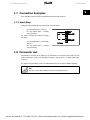
1.7.1 Start/Stop
Start/stop using terminal 18 and coasting stop using terminal 27.
Par. 302 Digital input = Start [7]
Par. 304 Digital input = Coasting
stop inverted [2]
For Precise start/stop the following settings
are made:
Par. 302 Digital input = Precise start/
stop [27]
Par. 304 Digital input = Coasting
stop inverted [2]
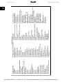
1.8 Parameter List
All parameters are listed in the following. For information on conversion index, data type and
further descriptions, please see Operating Instructions (MG.27.AX.YY) or Design Guide (MG.
27.EX.YY).
For external communication, please see dedicated literature (see section Available Literature).
NB!
Use MCT-10 and USB to RS485 converter to change parameters.
MG.28.M1.02 - VLT® is a registered Danfoss trademark
Phone: 800.894.0412 - Fax: 888.723.4773 - Web: www.ctiautomation.net - Email: [email protected]
21
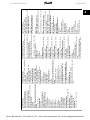
0-01 Language
*[0] English
[1] German
[2] French
[3] Danish
[4] Spanish
[5] Italian002 Local/Remote Operation
*[0] Remote operation
[1] Local operation
003 Local Reference
If par. 013 = [1] or [2]: 0 - fMAX, *50 Hz
If par. 013 = [3] or [4]: RefMIN - RefMAX, *0.0
004 Active Set-up
[0] Factory Set-up
*[1] Set-up 1
[2] Set-up 2
[3] Set-up 3
[4] Set-up 4
[5] Multi Set-up
005 Programming Set-up
[0] Factory Set-up
*[1] Set-up 1
[2] Set-up 2
[3] Set-up 3
[4] Set-up 4
*[5] Active Set-up
0-06 Set-up Copying
*[0] No copying
[1] Copy to Set-up 1 from #
[2] Copy to Set-up 2 from #
[3] Copy to Set-up 3 from #
[4] Copy to Set-up 4 from #
[5] Copy to all set-ups from #
007 LCP Copy
*[0] No copying
[1] Upload all parameters
[2] Download all parameters
[3] Download size-independent parameters
0-XX Operation/Display
Parameter Overwiev
013 Local Control
008 Display Scaling of Output Frequency
[0] Local not active
0.01 - 100.00, *1.00
[1] Local control and open loop without slip com009 Large Diplay Readout
pensation
[0] No readout
[2] Remote-operated control and open loop without
[1] Resulting reference [%]
slip compensation
[2] Resulting reference [unit]
[3] Local control as par. 100
[3] Feedback [unit]
*[4] Remote-operated contorl as par. 100014 Lo*[4] Frequency [Hz]
cal stop
[5] Output frequency x scaling
[0] Not active
[6] Motor current [A]
*[1] Active
[7] Torque [%]
015 Local Jog
[8] Power [kW]
*[0] Not active
[9] Power [HP]
[1] Active
[11] Motor voltage [V]
016 Local Reversing
[12] DC link voltage [V]
*[0] Not active
[13] Thermal load motor [%]
[1] Active
[14] Thermal load [%]
017 Local reset of Trip
[15] Running hours [Hours]
[0] Not active
[16] Digital input [Bin]
*[1] Active
[17] Analog input 53 [V]
018 Lock for Data Changes
[19] Analog input 60 [mA]
*[0] Not locked
[20] Pulse reference [Hz]
[1] Locked
[21] External reference [%]
019 Operating Mode at Power-up, Local Op[22] Status word [Hex]
eration
[25] Heatsink temperature [°C]
[0] Auto re-start, use saved reference
[26] Alarm word [Hex]
*[1] Forced stop, use saved reference
[27] Control word [Hex]
[2] Forced stop, set ref. to 0
[28] Warning word [Hex]
020 Hand Operation
[29] Extended status word [Hex]
*[0] Not active
[30] Communication option card warning
[1] Active
[31] Pulse count
024 Userdefined Quick Menu
010 Small Display Line 1.1
*[0] Not active
See par. 009.
[1] Active
*[17] Analog input 53
025 Quick Menu Set-up
011 Small Display Readout 1.2
Value 0 - 999, *000
See par. 009.
*[6] Motor Current [A]
Load and Motor
012 Small Display Readout 1.3
100 Configuration
*See par. 009.
*[0] Speed control, open loop
*[3] Feedback [unit]
1
[2] Speed control, closed loop
[3] Process control, closed loop
101 Torque Characteristic
*[1] Constant torque
[2] Variable torque low
[3] Variable torque medium
[4] Variable torque high
[5] Variable torque low with CT start
[6] Variable torque medium with CT start
[7] Variable torque high with CT start
[8] Special motor mode
102 Motor Power PM,N
0.25 - 22 kW, *Dep. on unit
103 Motor Voltage UM,N
For 200 V units: 50 - 999 V, *230 V
For 400 V units: 50 - 999 V, *400V
104 Motor Frequency fM,N
24 - 1000 Hz, *50 Hz
105 Motor Current IM,N
0.01 - IMAX, Dep. on motor
106 Rated Motor Speed
100 - fM,N x 60 (max. 60000 rpm), Dep. on par. 104
107 Automatic Motor Tuning, AMT
*[0] Optimisation off
[1] Optimisation on
108 Stator Resistance RS
0.000 - x.xxx Ω, *Dep. on motor
109 Stator Resistance XS
0.00 - x.xx Ω, *Dep. on motor
117 Resonance Damping
OFF - 100%
*OFF%
119 High Start Torque
0.0 - 0.5 s * 0.0 s
120 Start Delay
0.0 - 10.0 s * 0.0 s
1 Quick Guide
22
VLT 2800 Quick Guide
Phone: 800.894.0412 - Fax: 888.723.4773 - Web: www.ctiautomation.net - Email: [email protected]
MG.28.M1.02 - VLT® is a registered Danfoss trademark
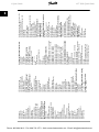
121 Start Function
[0] DC hold during start delay time
[1] DC brake during start delay time
*[2] Coasting during start delay time
[3] Start frequency/voltage clockwise
[4] Start frequency/voltage in reference direction
122 Function at Stop
*[0] Coasting
[1] DC hold
123 Min. Frequency for Activation of Function
at Stop
0.1 - 10 Hz, *0.1 Hz
126 DC Brake Time
0 - 60 s, *10 s
127 DC brake cut-in Frequency
0.0 (OFF) - Par. 202, *OFF
128 Thermal Motor Protection
*[0] No protection
[1] Thermistor warning
[2] Thermistor trip
[3] ETR warning 1
[4] ETR trip 1
[5] ETR warning 2
[6] ETR trip 2
[7] ETR warning 3
[8] ETR trip 3
[9] ETR warning 4
[10] ETR trip 4
130 Start Frequency
0.0 - 10.0 Hz, *0.0 Hz
131 Initial Voltage
0.0 - 200.0 V, *0.0 V
132 DC Brake Voltage
0 - 100% of max. DC brake voltage, *0%
133 Start Voltage
0.00 - 100.00 V, *Dep. on unit
134 Load Compensation
0.0 - 300.0%, 100,0%
135 U/f Ratio
0.00 - 20.00 at Hz, *Dep. on unit
136 Slip Compensation
0 - 150 % * 100 %-500 . +500% of rated slip compensation, *100%
137 DC Hold Voltage
0 - 100% if nax. DC hold voltage, *0%
138 Brake Cut Out Value
0.5 - 132.0/1000.0 Hz, *3.0 Hz
139 Brake Cut In Frequency
0.5 - 132.0/1000.0 Hz, *3.0 Hz
140 Current, Minimum Value
0% - 100% of inverter output current
142 Leakage Reactance XL
0.000 - xxx.xxx Ω, *Dep- on motor
143 Internal Fan Control
*[0] Automatic
[1] Always switched on
[2] Always switched off
144 Gain AC Brake
1.00 - 1.50, *1.30
146 Reset Voltage Vector
*[0] Off
[1] Reset
References and Limits200 Output Frequency
Range
*[0] Only clockwise, 0 - 132 Hz
[1] Both directions, 0 - 132 Hz
[2] Counterclockwise only, 0 - 132 Hz
[4] Both directions, 0 - 1000 Hz
[5] Counterclokcwise only, 0 - 1000 Hz
201 Output Frequency Low Limit, fMIN
0.0 - fMAX, *0.0 Hz
202 Output Frequency High Limit, FMAX
fMIN - 132/1000 Hz (par. 200 Output frequency
range, 132 Hz
203 Reference Range
[0] Min. reference - Max. reference
[1] Analog Input 53 -Max. reference - +Max. reference
204 Minimum Reference, RefMIN
Par. 100 [0]. -100,000.000 - par. 205 RefMAX, *0.000
Hz
Par. 100 [1]/[3], -par. 414 Minimum feedback - par.
205 RefMAX, *0.000 rpm/par. 416
205 maximum Reference, RefMAX
Par. 100 [0]. Par. 204 RefMIN - 1000.000 Hz, *50.000
Hz
Par. 100 [1]/[3]. Par. 204 RefMIN - Par. 415 Max
Feedback, *50.000 rpm/par. 416
206 Ramp Type
*[0] Linear
[1] Sin shaped
[2] Sin2
207 Ramp-up Time 1
0.02 - 3600.00 s, * 3.00 s (VLT 2803 - 2875), *
10.00 (2880 - 2882)
208 Ramp-down Time 1
0.02 - 3600.00 s, * 3.00 s (VLT 2803 - 2875), *
10.00 (2880 - 2882)
209 Ramp-up Time 2
0.02 - 3600.00 s, * 3.00 s (VLT 2803 - 2875), *
10.00 (2880 - 2882)
210 Ramp-down Time 2
0.02 - 3600.00 s, * 3.00 s (VLT 2803 - 2875), *
10.00 (2880 - 2882)
211 Jog Ramp Time
0.02 - 3600.00 s, * 3.00 s (VLT 2803 - 2875), *
10.00 (2880 - 2882)
212 Quick-stop Ramp-down Time
0.02 - 3600.00 s, * 3.00 s (VLT 2803 - 2875), *
10.00 (2880 - 2882)
213 Jog Frequency
0.0 - Par. 202 Output Frequency High Limit, fMAX
214 Reference Function
*[0] Sum
[1] Relative
[2] External/preset
215-218 Preset reference 1-4
0.0 - 400.0 Hz * 0.0 Hz-100.00% - +100.00%, *
0.00%
219 Catch Up/Slow Down Reference
0.00 - 100% of the given reference, * 0.00%
302 Terminal 18 Digital Input
[0] No function
[1] Reset
[2] Coasting stop inverse
[3] Reset and coasting inverse
[4] Quick-stop inverse
[5] DC braking inverse
[6] Stop inverse
*[7] Start
[8] Pulse start
[9] Reversing
[10] Reversing
[11] Start Clockwise
[12] Start counterclockwise
[13] Jog
[14] Freeze reference
[15] Freeze output frequency
Inputs and Outputs
HIGH, *0.0 Hz
226 Warning: High Frequency fHIGH
If par. 200 = [0]/[1]. Par. 225 fLOW - 132 Hz, * 132.0
Hz
If par. 200 [2]/[3]. Par 225 fLOW - 1000 Hz, * 132.0
Hz
227 Warning: Low Feedback, FBLOW
0.0 - 400.0 Hz * 0.0 Hz-100,000.000 - par. 228
Warn.: FBHIGH, * -4000.000
228 Warning: High Feedback, FBHIGH
Par. 227 Warn.: FBLOW - 100,000.000, * 4000.000
229 Frequency Bypass, Bandwidth
0 (OFF) - 100 Hz, * 0 Hz
230 - 231 Frequency Bypass 1 - 2
0 - 100 Hz, *0.0 Hz
221 Current Limit, ILIM
0 - xxx.x% of par. 105, * 160%
223 Warning, Low Current, ILOW
0.0 - par. 224 Warning: High Current, IHIGH, * 0.0 A
224 Warning: High Current, IHIGH
0 - IMAX, * IMAX
225 Warning: Low Frequency, fLOW
0.0 - par. 226 Warn.: High frequency, f
VLT 2800 Quick Guide
1 Quick Guide
1
Phone: 800.894.0412 - Fax: 888.723.4773 - Web: www.ctiautomation.net - Email: [email protected]
MG.28.M1.02 - VLT® is a registered Danfoss trademark
23
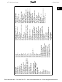
[16] Speed up
[17] Speed down
[19] Catch up
[20] Slow down
[21] Ramp 2
[22] Preset ref, LSB
[23] Preset ref, MSB
[24] Preset reference on
[25] Thermistor
[26] Precise stop
[27] Precise Start Stop
[31] Selection of Set-up, LSB
[32] Selection of Set-up, MSB
[33] Reset and start
[34 Pulse counter start
303 Terminal 19 Digital Input
See par. 302 * [9] Reversing
304 Terminal 27 Digital Input
[0] No function
[1] Reset
[2] Coasting stop inverse
*[3] Reset and coasting inverse
[4] Quick-stop inverse
[5] DC braking inverse
[6] Stop inverse
[7] Start
[8] Pulse start
[9] Reversing
[10] Reversing
[11] Start Clockwise
[12] Start counterclockwise
[13] Jog
[14] Freeze reference
[15] Freeze output frequency
[16] Speed up
[17] Speed down
[19] Catch up
[20] Slow down
[21] Ramp 2
[22] Preset ref, LSB
[23] Preset ref, MSB
[24] Preset reference on
[25] Thermistor
[26] Precise stop
[27] Precise Start Stop
[31] Selection of Set-up, LSB
[32] Selection of Set-up, MSB
[33] Reset and start
[34 Pulse counter start
305 Terminal 29 Digital Input
See par. 305 * [13] Jog
307Terminal 33 Digital Input
*[0] No function
[1] Reset
[2] Coasting stop inverse
[3] Reset and coasting inverse
[4] Quick-stop inverse
[5] DC braking inverse
[6] Stop inverse
[7] Start
[8] Pulse start
[9] Reversing
[10] Reversing
[11] Start Clockwise
[12] Start counterclockwise
[13] Jog
[14] Freeze reference
[15] Freeze output frequency
[16] Speed up
[17] Speed down
[19] Catch up
[20] Slow down
[21] Ramp 2
[22] Preset ref, LSB
[23] Preset ref, MSB
[24] Preset reference on
[28] Pulse reference
[29] Pulse feedback
[30] Pulse input
[31] Selection of Set-up, LSB
[32] Selection of Set-up, MSB
[33] Reset and start
308 Terminal 53, Analog Input Voltage
[0] No function
*[1] Reference
[2] Feedback
[3] Wobble 309 Terminal 53 Min. Scaling
0.0 - 10.0 V, * 0.0 V
310 Terminal 53 Max. Scaling
0.0 - 10.0 V, * 10.0 V
314 Terminal 60 Analog Input Current
[0] No function
[1] Reference
*[2] Feedback
[10] Wobble
315 Terminal 60 Min. Scaling
0.0 - 20.0 mA, * 4.0 mA
316 Terminal 60 Max. Scaling
0.0 - 20.0 mA, * 20.0 mA
317 Time Out
1 - 99 s * 10 s
318
*[0] No operation
[1] Freeze output frequency
[2] Stop
[3] Jog
[4] Max speed
[5] Stop and trip
319 Analog output terminal 42
[0] No function
[1] External reference min. - max. 0 - 20 mA
[2] External reference min. - max. 4- 20 mA
[3] Feedback min. - max. 0-20 mA
[4] Feedback min. - max. 4- 20 mA
[5] Output frequency 0 - max 0-20 mA
[6] Output frequency 0 - max 4-20 mA
*[7] Output current 0 - IINV 0-20 mA
[8] Output current 0 - IINV 4-20 mA
[9] Output power 0-PM,N 0-20 mA
[10] Output power 0-PM,N 4-20 mA
[11] Inverter temperature 20-100 °C 0-20 mA
[12] Inverter temperature 20-100 °C 4-20 mA
323 Relay Output 1-3
[0] No function
*[1] Unit ready
[2] Enable/no warning
[3] Running
[4] Running in reference, no warning
[5] Running, no warning
[6] Running in reference range, no warnings
[7] Ready - mains voltage within range
[8] Alarm or warning
[9] Current higher than current limit
[10] Alarm
[11] Output frequency higher than fLOW
[12] Output frequency lower than fHIGH
[13] Output current higher than ILOW
24
400 Brake Function
[0] OFF
[1] Resistor brake
[4] AC brake
[5] Load sharing
Special Functions
1
[14] Output current lower than IHIGH par. 224
[15] Feedback higher than FBLOW
[16] Feedback lower than FBHIGH par. 228
[17] Relay 123
[18] Reversing
[19] Thermal warning
[20] Local operation
[22] Out of frequency range par. 225/226
[23] Out of current range
[24] Out of feedback range
[24] Mechanical brake control
[25] Control word bit 11
327 Pulse reference/feedback
150 - 67600 Hz, * 5000 Hz
328 Maximum Pulse 29
150 - 67600 Hz, * 5000 Hz
341 Digital/Pulse Output Terminal 46
[0] Unit ready
Par. [0] - [20], see par. 323
[21] Pulse reference
Par. [22] - [25], see par. 323
[26] Pulse feedback
[27] Output frequency
[28] Pulse current
[29] Pulse power
[30] Pulse temperature
342 Terminal 46, max. Pulse Scaling
150 - 10000 Hz, * 5000 Hz
343 Precise Stop Function
*[0] Precise ramp stop
[1] Counter stop with reset
[2] Counter stop without reset
[3] Speed-compensated counter stop
[4] Speed-compensated stop with reset
[5] Speed-compensated stop without reset
344 Counter Value
0 - 999999, * 100000 pulses
349 Speed Comp Delay
0 ms - 100 ms, * 10 ms
1 Quick Guide
VLT 2800 Quick Guide
Phone: 800.894.0412 - Fax: 888.723.4773 - Web: www.ctiautomation.net - Email: [email protected]
MG.28.M1.02 - VLT® is a registered Danfoss trademark
405 Reset Function
*[0] Manual reset
[1] Automatic reset x 1
[3] Automatic reset x 3
[10] Automatic reset x 10
[11] Reset at power-up
406 Automatic Restart Time
0 - 10 s, * 5 s
409 Trip Delay Overcurrent, ILIM
0 - 60 s (61 = OFF), * OFF
411 Switching Frequency
3000 - 14000 Hz (VLT 2803 - 2875), * 4500 Hz
3000 - 10000 Hz (VLT 2880 - 2882), * 4500 Hz
412 Variable Switching Frequency
*[2] Without LC-filter
[3] LC-filter connected
413 Overmodulation Function
[0] OFF
*[1] ON
414 Minimum Feedback, FBMIN
-100,000.000 - par. 415, FBMAX, * 0.000
415 Maximum Feedback, FBMAX
FBMIN - 100,000.000, * 1500.000
416 Process Units
*[0] No unit
[1] %
[2] ppm
[3] rpm
[4] bar
[5] Cycles/min
[6] Pulses/s
[7] Units/s
[8] Units/min
[9] Units/h
[10] ° C
[11] Pa
[12] I/s
[13] m3/s
[14] l/min
[15] m3/min
[16] l/h
[17] m3/h
[18] Kg/s
[19] Kg/min
[20] Kg/h
[21] T/min
[22] T/h
[23] Metres
[24] Nm
[25] m/s
[26] m/min
[27] ° F
[28] In wg
[29] Gal/s
[30] Ft3/s
[31] Gal/min[32] Ft3/min
[33] Gal/h
[34] Ft3/h
[35] Lb/s
[36] Lb/min
[37] Lb/h
[38] Lb ft
[39] Ft/s
[40] Ft/min
417 Speed PID Proportional Gain
0.000 (OFF) - 1.000, * 0.010
418 Speed PID Integral Time
20.00 - 999.99 ms (1000 - OFF), * 100 ms
419 Speed PID Differential Time
0.00 (OFF) - 200.00 ms, * 20.00 ms
420 Speed PID D-Gain Limit
5.0 - 50.0, * 5.0
421 Speed PID Lowpass Filter Time
20 - 500 ms, * 100 ms
456 Brake Voltage Reduce
423 U1 Voltage0.0 - 999.0 V, * par. 103
0 - 25 V if 200 V, * 0
424 F1 Frequency
0 - 50 V if 400 V, * 0
0.0 - par. 426, F2 frequency, * Par. 104
461 Feedback Conversion
425 U2 Voltage
*[0] Linear
0.0 - 999.0 V, * par. 103
[1] Square root
426 F2 Frequency
Par. 424, F1 frequency - Par. 428, F3 frequency, * 462 Enhanced Sleep Mode Timer
Value 0 - 9999 s, * 0 = OFF
par. 104
463 Boost Setpoint
427 U3 Voltage
1 - 200%, * 100% of setpoint
0.0 - 999.0 V, * par. 103
464 Wakeup Pressure
428 F3 Frequency
Par. 204, RefMIN - par. 215-218 setpoint, * 0
Par. 426, F2 frequency - 1000 Hz, * par. 104
437 Process PID Normal/Inverse Control
465 Minimum Pump Frequency
*[0] Normal
Value par. 201, fMIN - par. 202 fMAX (Hz), * 20
[1] Inverse
466 Maximum Pump Frequency
438 Process PID Anti Windup
Value par. 201, fMIN - par. 202 fMAX (Hz), * 50
[0] Not active
467 Minimum Pump Power
[1] Active
0 - 500.000 W, * 0
Process PID Start Frequency
468 Maximum Pump Power
fMIN - fMAX (par. 201 - par. 202), * par. 201
0 - 500.000 W, * 0
440 Process PID Proportional Gain
469 No Flow Power Compensation
0.0 - 10.00, * 0.01
0.01 - 2, * 1.2
441 Process PID Integration Time
470 Dry Run Time Out
0.00 (OFF) - 10.00 s, * OFF
5 - 30 s, * 31 = OFF
442 Process PID Differentiation Time
471 Dry Run Interlock Timer
0.00 (OFF) - 10.00 s, * 0.00 s
0.5 - 60 min., * 30 min.
443 Process PID Diff. Gain Limit
484 Initial Ramp
5.0 - 50.0, * 5.0
OFF/000.1 s - 360.0 s, * OFF
444 Process PID Lowpass Filter Time
485 Fill Rate
0.02 - 10.00, * 0.02
OFF/000000.001 - 999999.999 (units/s), * OFF
445 Flying Start
486 Filled Setpoint
*[0] OFF
Par. 414 - par. 205, * par. 414
[1] OK - same direction
[2] OK - both directions
[2] DC brake and start
451 Speed PID Feedforward Factor
0 - 500 %, * 100 %
452 Controller Range
0 - 200 %, * 10 %
VLT 2800 Quick Guide
1 Quick Guide
Phone: 800.894.0412 - Fax: 888.723.4773 - Web: www.ctiautomation.net - Email: [email protected]
MG.28.M1.02 - VLT® is a registered Danfoss trademark
1
25
1 Quick Guide
1
VLT 2800 Quick Guide
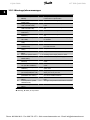
1.9.1 Warnings/alarm messages
No.
2
Description
Live zero error (LIVE ZERO
ERROR)
4
Mains phase loss (MAINS
PHASE LOSS)
5
Voltage warning high (DC
LINK VOLTAGE HIGH)
6
Voltage warning low (DC
LINK VOLTAGE LOW)
7
Overvoltage (DC LINK
OVERVOLT)
8
Undervoltage (DC LINK UNDERVOLT)
9
Inverter overload (INVERTER TIME)
10
Motor overloaded ( MOTOR,
TIME)
11
Motor thermistor (MOTOR
THERMISTOR)
12
Current limit (CURRENT
LIMIT)
13
Overcurrent (OVERCURRENT)
14
Earth fault (EARTH FAULT)
15
Switch mode fault (SWITCH
MODE FAULT)
16
Short-circuit (CURR. SHORT
CIRCUIT)
17
Serial communication timeout (STD BUS TIMEOUT)
18
HPFB bus timeout (HPFB
TIMEOUT)
33
Out of frequency range
(OUT FREQ RNG/ROT LIM)
34
HPFB communication fault
(PROFIBUS OPT. FAULT)
35
Inrush fault (INRUSH
FAULT)
36
Overtemperature (OVERTEMPERATURE)
37-45 Internal fault (INTERNAL
FAULT)
W A T
Cause of Problem
X X X Voltage or current signal on terminals 53 or 60
is below 50% of preset value.
X X X No phase on mains supply side.
X
The intermediate circuit voltage exceeds the limit set.
X
The intermediate circuit voltage is lower the limit
set.
X X X The intermediate voltage exceeds the limit set.
X X X The intermediate voltage is lower than the limit
set.
X X
The frequency converter is close to tripping due
to overload.
X X
The motor is too hot due to overload.
X X
X X
Either the motor is too hot or the thermistor has
been disconnected.
Output current is higher than set in par. 221.
X X X The peak current limit has been exceeded.
X X Discharge from output phases to earth.
X X Fault in switch mode power supply.
X
X
X
X
X
X X Short-circuit on the motor terminals or in the
motor.
X
No serial communication to the frequency converter.
X
No serial communication to the communication
option card.
Output frequency has reached the limit set in
either par. 201 or par. 202.
X
Fault only occurs in fieldbus versions. Please see
par. 953 in fieldbus literature.
X X Connected to mains too many times within 1 minute.
X
The upper temperature limit has been exceeded.
X X Please contact Danfoss.
W: Warning, A: Alarm, T: Trip locked
26
MG.28.M1.02 - VLT® is a registered Danfoss trademark
Phone: 800.894.0412 - Fax: 888.723.4773 - Web: www.ctiautomation.net - Email: [email protected]
VLT 2800 Quick Guide
No.
50
51
54
55
56
99
1 Quick Guide
Description
AMT not possible
W A T
Cause of Problem
X
Either RS value is outside permitted limits, or
motor current is too low on at least one phase,
or the motor is too small for AMA.
AMT fault re. nameplate daX
Inconsistency between registered motor data.
ta (AMT TYPE.DATA FAULT)
AMT wrong motor (AMT
X
AMA has detected a missing motor phase.
WRONG MOTOR)
AMT timeout (AMT TIMEX
Calculations are taking too long, probably
OUT)
caused by noise on motor cables.
AMT warning during AMT
X
Warning is given while AMA is performed.
(AMT WARN. DURING AMT)
Locked (LOCKED)
X
See par. 018.
1
W: Warning, A: Alarm, T: Trip locked
A warning or an alarm will appear in the display as a numerical code Err. xx. A warning will be
shown on the display until the fault has been corrected, while an alarm will continue to flash until
the [STOP/RESET] key is activated.The table shows the various warnings and alarms, and whether
the fault locks the frequency converter. After a Trip locked the mains supply is cut off and the
fault is corrected. The mains supply is reconnected and the frequency converter is reset. The
frequency converter is now ready. A Trip can be reset manually in three ways:
1.
Via the operating key [STOP/RESET].
2.
Via a digital input.
3.
Via serial communication.
It is also possible to choose an automatic reset in parameter 405 Reset function. When a cross
appears in both warning and alarm, this can mean that a warning comes before an alarm. It can
also mean that it is possible for the user to programme whether a warning or an alarm will appear
for a given fault. For example, this is possible in parameter 128 Motor thermal protection. After a
trip the motor will coast, and alarm and warning will blink on the frequency converter, but if the
fault disappears only the alarm will blink. After a reset the frequency converter will be ready to
start operation again.
MG.28.M1.02 - VLT® is a registered Danfoss trademark
Phone: 800.894.0412 - Fax: 888.723.4773 - Web: www.ctiautomation.net - Email: [email protected]
27
1 Quick Guide
1
VLT 2800 Quick Guide
1.10 Specifications
1.10.1 Mains Suply 200 - 400 V
According to . international
Type 2803 2805 2807 2811 2815 2822
standards
Output current
IINV. [A] 2.2
3.2
4.2
6.0
6.8
9.6
IMAX (60s) [A] 3.5
5.1
6.7
9.6 10.8 15.3
(3 x 200-240V)
Output power
SINV. [KVA] 0.9
1.3
1.7
2.4
2.7
3.8
(230 V)
Typical shaft outPM,N [kW] 0.37 0.55 0.75 1.1
1.5
2.2
put
Typical shaft outPM,N [HP] 0.5 0.75 1.0
1.5
2.0
3.0
put
Max. cable cross
[mm2/AWG] 4/10 4/10 4/10 4/10 4/10 4/10
section, motor
Input current
(1 x 220-240 V)
Input current
(3 x 200-240 V)
Max. cable cross
section, power
Max. pre-fuses
Efficiency
Power loss at
100% load
Weight
Enclosure
IL,N [A] 5.9
8.3 10.6
IL,MAX (60s) 9.4 13.3 16.7
[A]
IL,N [A] 2.9
4.0
5.1
IL,MAX (60s) 4.6
6.4
8.2
[A]
[mm2/AWG] 4/10 4/10 4/10
2822 2840 2840
PD2
PD2
9.6
16
16
10.6 25.6 17.6
3.8
6.4
6.4
2.2
3.7
3.7
3.0
5.0
5.0
4/10 4/10 16/6
14.5
23.2
15.2
24.3
-
22.0
24.3
-
31.0
34.5
7.0
11.2
7.6
12.2
8.8
14.1
8.8
9.7
14.7
23.5
14.7
16.2
4/10 4/10 4/10 4/10 4/10 16/6
IEC/UL [A] 20/2 20/2 20/2 20/2 20/2 20/2 35/3 25/2 50/5
0
0
0
0
0
0
5
5
0
[%] 95
95
95
95
95
95
95
95
95
[W] 24
35
48
69
94
125 125 231 231
[kg] 2.0
2.0
2.0
2.0
2.0
3,7
6.0
6.0
18.5
0
type IP 20 IP 20 IP 20 IP 20 IP 20 IP 20 IP 20 IP 20 IP
20/
NEM
A1
1.10.2 Mains Supply 380 - 480 V
According to international
standards
Output current
(3 x 380-480V)
Output power (400
V)
Typical shaft output
Typical shaft output
Max. cable cross
section, motor
Input current
(3 x 380-480 V)
Max. cable cross
section, power
Max. pre-fuses
Efficiency
Power loss at 100%
load
Weight
Enclosure
28
Type
2805
2807
2811
2815
2822
2830
IINV. [A]
IMAX (60s) [A]
SINV. [KVA]
1.7
2.7
1.1
2.1
3.3
1.7
3.0
4.8
2.0
3.7
5.9
2.6
5.2
8.3
3.6
7.0
11.2
4.8
PM,N [kW]
0.55
0.75
1.1
1.5
2.2
3.0
PM,N [HP]
0.75
1.0
1.5
2.0
3.0
4.0
[mm2/AWG]
4/10
4/10
4/10
4/10
4/10
4/10
IL,N [A]
IL,MAX(60s)[A]
[mm2/AWG]
1.6
2.6
4/10
1.9
3.0
4/10
2.6
4.2
4/10
3.2
5.1
4/10
4.7
7.5
4/10
6.1
9.8
4/10
IEC/UL [A]
[%]
[W]
20/20
96
28
20/20
96
38
20/20
96
55
20/20
96
75
20/20
96
110
20/20
96
150
[kg]
2.1
type IP 20
2.1
IP 20
2.1
IP 20
2.1
IP 20
3.7
IP 20
3.7
IP 20
MG.28.M1.02 - VLT® is a registered Danfoss trademark
Phone: 800.894.0412 - Fax: 888.723.4773 - Web: www.ctiautomation.net - Email: [email protected]
VLT 2800 Quick Guide
1 Quick Guide
According to international
standards
Output current
(3 x 380-480V)
Output power (400
V)
Typical shaft output
Typical shaft output
Max. cable cross
section, motor
Input current
(3 x 380-480 V)
Max. cable cross
section, power
Max. pre-fuses
Efficiency
Power loss at
100% load
Weight
Enclosure
Type
2840
2855
2875
2880
2881
2882
IINV. [A]
IMAX (60s) [A]
SINV. [KVA]
9.1
14.5
6.3
12
19.2
8.3
16
25.6
11.1
24
38.4
16.6
32.0
51.2
22.2
37.5
60.0
26.0
PM,N [kW]
4.0
5.5
7.5
11.0
15.0
18.5
PM,N [HP]
5.0
7.5
10.0
15.0
20.0
25.0
[mm2/AWG]
4/10
4/10
4/10
16/6
16/6
16/6
IL,N [A]
IL,MAX(60s)[A]
[mm2/AWG]
8.1
13.0
4/10
10.6
17.0
4/10
14.9
23.8
4/10
24.0
38.4
16/6
32.0
51.2
16/6
37.5
60
16/6
IEC/UL [A] 20/20
[%]
96
[W] 200
25/25
96
275
25/25
96
372
50/50
97
412
50/50
97
562
50/50
97
693
6.0
IP20
6.0
IP20
[kg]
type
3.7
IP20
1
18.5
18.5
18.5
IP20/
IP20/
IP20/
NEMA 1 NEMA 1 NEMA 1
1.11 General Specifications
Mains supply (L1, L2, L3):
Supply voltage VLT 2803-2840 220-240 V (N, L1)
Supply voltage VLT 2803-2840 200-240 V
Supply voltage VLT 2805-2882 380-480 V
Supply voltage VLT 2805-2840 (R5)
Supply frequency
Max. imbalance on supply voltage
True Power Factor (λ)
Displacement Power Factor (cos φ)
Number of connections at supply input L1, L2, L3
Max. short-circuit value
1 x 220/230/240 V ±10%
3 x 200/208/220/230/240 V ±10%
3 x 380/400/415/440/480 V ±10%
380 / 400 V + 10 %
50/60 Hz ± 3 Hz
± 2.0% of rated supply voltage
0.90 nominal at rated load
near unity (> 0.98)
2 times/min.
100,000 A
See Special Conditions section in the Design Guide
Output data (U, V, W):
Output voltage
Output frequency
Rated motor voltage, 200-240 V units
Rated motor voltage, 380-480 V units
Rated motor frequency
Switching on output
Ramp times
0 - 100% of supply voltage
0.2 - 132 Hz, 1 - 1000 Hz
200/208/220/230/240 V
380/400/415/440/460/480 V
50/60 Hz
Unlimited
0.02 - 3600 sec.
Torque characteristics:
Starting torque (parameter 101 Torque characteristic = Constant torque)
Starting torque (parameter 101 Torque characteristics = Variable torque)
Starting torque (parameter 119 High starting torque )
Overload torque (parameter 101 Torque characteristic = Constant torque)
Overload torque (parameter 101 Torque characteristic = Variable torque)
160% in 1 min.*
160% in 1 min.*
180% for 0.5 sec.
160%*
160%*
Percentage relates to frequency converter's nominal current.
* VLT 2822 PD2 / 2840 PD2 1 x 220 V only 110% in 1 min.
MG.28.M1.02 - VLT® is a registered Danfoss trademark
Phone: 800.894.0412 - Fax: 888.723.4773 - Web: www.ctiautomation.net - Email: [email protected]
29
1 Quick Guide
VLT 2800 Quick Guide
Control card, digital inputs:
Number of programmable digital inputs
Terminal number
Voltage level
Voltage level, logic '0'
Voltage level, logic '1'
Maximum voltage on input
Input resistance, Ri (terminals 18, 19, 27, 29)
Input resistance, Ri (terminal 33)
1
5
18, 19, 27, 29, 33
0 - 24 V DC (PNP positive logic)
< 5 V DC
> 10 V DC
28 V DC
approx. 4 kΩ
approx. 2 kΩ
All digital inputs are galvanically isolated from the supply voltage (PELV) and other high-voltage
terminals. See section entitled Galvanic Isolation in the Operating Instructions.
Control card, analog inputs:
Number of analog voltage inputs
Terminal number
Voltage level
Input resistance, Ri
Max. voltage
Number of analog current inputs
Terminal number
Current level
Input resistance, Ri
Max. current
Resolution for analog inputs
Accuracy of analog inputs
Scan interval
1 pcs.
53
0 - 10 V DC (scaleable)
approx. 10 kΩ
20 V
1 pcs.
60
0/4 - 20 mA (scaleable)
approx. 300 Ω
30 mA
10 bit
Max. error 1% of full scale
13.3 msec
The analog inputs are galvanically isolated from the supply voltage (PELV) and other high-voltage
terminals. See section entitled Galvanic Isolation in the Operating Instructions.
Control card, pulse inputs:
Number of programmable pulse inputs
Terminal number
Max. frequency at terminal 33
Max. frequency at terminal 33
Min. frequency at terminal 33
Voltage level
Voltage level, logic '0'
Voltage level, logic '1'
Maximum voltage on input
Input resistance, Ri
Scan interval
Resolution
Accuracy (100 Hz- 1 kHz) terminal 33
Accuracy (1 kHz - 67.6 kHz) terminal 33
1
33
67.6 kHz (Push-pull)
5 kHz (open collector)
4 Hz
0 - 24 V DC (PNP positive logic)
< 5 V DC
> 10 V DC
28 V DC
approx. 2 kΩ
13.3 msec
10 bit
Max. error: 0.5% of full scale
Max. error: 0.1% of full scale
The pulse input (terminal 33) is galvanically isolated from the supply voltage (PELV) and other
high-voltage terminals. See section entitled Galvanic Isolation in the Operating Instructions.
Control card, digital/frequency output:
Number of programmable digital/pulse outputs
Terminal number
Voltage level at digital/frequency output
Max. output current at digital/frequency output
Max. load at digital/frequency output
Max. capacity at frequency output
Minimum output frequency at frequency output
Maximum output frequency at frequency output
30
1 pcs.
46
0 - 24 V DC (O.C PNP)
25 mA.
1 kΩ
10 nF
16 Hz
10 kHz
MG.28.M1.02 - VLT® is a registered Danfoss trademark
Phone: 800.894.0412 - Fax: 888.723.4773 - Web: www.ctiautomation.net - Email: [email protected]
VLT 2800 Quick Guide
1 Quick Guide
Accuracy on frequency output
Resolution on frequency output
Max. error: 0.2 % of full scale
10 bit
The digital output is galvanically isolated from the supply voltage (PELV) and other high-voltage
terminals. See section entitled Galvanic Isolation in the Operating Instructions.
Control card, analog output:
Number of programmable analog outputs
Terminal number
Current range at analog output
Max. load to common at analog output
Accuracy on analog output
Resolution on analog output
1
1
42
0/4 - 20 mA
500 Ω
Max. error: 1.5 % of full scale
10 bit
The analog output is galvanically isolated from the supply voltage (PELV) and other high-voltage
terminals. See section entitled Galvanic Isolation in the Operating Instructions.
Control card, 24 V DC output:
Terminal number
Max. load
12
130 mA
The 24 V DC supply is galvanically isolated from the supply voltage (PELV) , but has the same
potential as the analogue and digital inputs and outputs. See section entitled Galvanic Isolation
in the Operating Instructions.
Control card, 10 V DC output:
Terminal number
Output voltage
Max. load
50
10.5 V ±0.5 V
15 mA
The 10 V DC supply is galvanically isolated from the supply voltage (PELV) and other high-voltage
terminals. See section entitled Galvanic Isolation in the Operating Instructions.
Control card, RS 485 serial communication:
Terminal number
Terminal number 67
Terminal number 70
68 (TX+, RX+), 69 (TX-, RX-)
+5V
Common for terminals 67, 68 and 69
Full galvanic isolation. See section entitled Galvanic Isolation in the Operating Instructions.
For CANopen/DeviceNet units, see VLT 2800 DeviceNet manual, MG.90.BX.YY.
Relay outputs:1)
Number of programmable relay outputs
Terminal number, control card (resisitvie and inductive load)
Max. terminal load (AC1) on 1-3, 1-2, control card
Max. terminal load (DC1 (IEC 947)) on 1-3, 1-2, control card
Min. terminal load (AC/DC) on 1-3, 1-2, control card
1
1-3 (break), 1-2 (make)
250 V AC, 2 A, 500 VA
25 V DC, 2 A /50 V DC, 1A, 50W
24 V DC 10 mA, 24 V AC 100 mA
The relay contact is separated from the rest of the circuit by strengthened isolation.
Note: Rated values resistive load - cosΦ >0.8 for up to 300,000 operations.
Inductive loads at cosΦ 0.25 approximately 50% load or 50% life time.
Cable lengths and cross sections:
Max. motor cable length, screened/armoured cable
Max. motor cable length, unscreened/unarmoured cable
Max. motor cable length, screened/armoured cable and motor coil
Max. motor cable length, unscreened/unarmoured cable and motor coil
Max. motor cable length, screened/armoured cable and RFI/1B filter
Max. motor cable length, screened/armoured cable and RFI/1B filter
Max. motor cable length, screened/armoured cable and RFI 1B/LC filter
40
75
100
200
200 V, 100
400 V, 25
400 V, 25
m
m
m
m
m
m
m
Max. cross section to motor, see next section.
MG.28.M1.02 - VLT® is a registered Danfoss trademark
Phone: 800.894.0412 - Fax: 888.723.4773 - Web: www.ctiautomation.net - Email: [email protected]
31
1 Quick Guide
VLT 2800 Quick Guide
Max. cross section to control wires, rigid wire
1.5 mm2/16 AWG (2 x 0.75 mm2)
Max. cross section to control cables, flexible cable
1 mm2/18 AWG
Max. cross section to control cables, cable with enclosed core
0.5 mm2/20 AWG
1
When complying with EN 55011 1A and EN 55011 1B the motor cable must in certain
instances be reduced. See EMC emission.
Control characteristics:
Frequency range
0.2 - 132 Hz, 1 - 1000 Hz
Resolution of output frequency
0.013 Hz, 0.2 - 1000 Hz
Repeat accuracy of Precise start/stop(terminals 18, 19)
± 0.5 msec
System response time (terminals 18, 19, 27, 29, 33)
26.6 msec
Speed control range (open loop)
1:10 of synchronous speed
Speed control range (closed loop)
1:120 of synchronous speed
Speed accuracy (open loop)
150 - 3600 rpm: Max. error of ±23 rpm
Speed accuracy (closed loop)
30 - 3600 rpm: Max. error of ±7.5 rpm
All control characteristics are based on a 4-pole asynchronous motor
Surroundings:
Enclosure
Enclosure with options
Vibration test
Max. relative humidity
Ambient temperature
IP 20
NEMA 1
0.7 g
5% - 93% during operation
Max. 45 °C (24-hour average max. 40 °C)
Derating for high ambient temperature, see special conditions in the Design Guide
Min. ambient temperature during full-scale operation
Min. ambient temperature at reduced performance
Temperature during storage/transport
Max. altitude above sea level
0 °C
- 10 °C
-25 - +65/70 °C
1000 m
Derating for high air pressure, see special conditions in the Design Guide
EMC standards, Emission
EMC standards, Immunity
EN 61000-6-4, EN 61800-3, EN 55011
EN 61000-6-1/2, EN 61000-4-2, EN 61000-4-3, EN 61000-4-4, EN
61000-4-5, EN 61000-4-6, EN 61800-3
See section on special conditions in the Design Guide
Safeguards:
•
Electronic thermal motor protection against overload.
•
Temperature monitoring of the power module ensures that the frequency converter cuts
out if the temperature reaches 100 °C. An overload temperature cannot be reset until
the temperature of the power module is below 70 °C.
1.12 Special Conditions
1.12.1 Aggressive Environments
The frequency converter is not to be installed in environments, where liquids, particles or gases are in the air that would impact and damage the electronics. Unless
the necessary measures are taken to protect the frequency converter, there is a risk
of stoppages, which reduce the service life of the frequency converter.
Aggressive gases, such as sulphur, nitrogen and chlorine compounds, together with high humidity
and temperature, facilitate possible chemical processes on the components of the frequency converter. These chemical processes quickly impact and damage the electronics. In these areas,
32
MG.28.M1.02 - VLT® is a registered Danfoss trademark
Phone: 800.894.0412 - Fax: 888.723.4773 - Web: www.ctiautomation.net - Email: [email protected]
VLT 2800 Quick Guide
1 Quick Guide
cabinet fitting with fresh-air circulation in the cabinet is recommended, thereby ensuring that
aggressive gases are kept away from the frequency converter.
1
NB!
Fitting of frequency converters in aggressive environments increases the risk of
stoppages, in addition to considerably reducing the service life of the unit.
Before the frequency converter is installed, it must be checked whether there are liquids, particles
or gases in the air. This can be done by looking at existing installations in the same environment.
Typical indicators of harmful airborne liquids are water or oil on metal parts or corrosion of metal
parts. Too many dust particles are typically observed on top of installation cabinets and on existing
electrical installations. Indicators that there are aggressive gases in the air are copper rails and
cable ends that are black on existing electrical installations.
1.12.2 Derating for Ambient Temperature
The ambient temperature measured over 24 hours should be at least 5° C lower than the max.
ambient temperature.
If the frequency converter is operated above 45° C, the continuous output current should be
decreased.
1.12.3 Derating for Low Air Pressure
Above 1000 m the ambient temperature or max. output current must be derated.
For altitudes above 2000 m, please contact Danfoss regarding PELV.
1.12.4 Derating for Running at Low Speeds
When a motor is connected to at frequency converter, it is necessary to check that the cooling of
the motor is adequate.
A problem may occur at low speeds in constant torque applications. Running continuously at low
speeds – below half the nominal motor speed – may require additional air cooling. Alternatively,
choose a larger motor (one size up).
1.12.5 Derating for Long Motor Cables
The frequency converter has been tested using a 75 m unscreened/unarmoured cable and a 25
m screened/armoured cable and has been designed to work using a motor cable with a rated
cross-section. If a cable with a larger cross-section is required, it is recommended to reduce the
output current by 5% for each step the cable cross-section is increased. (Increased cable crosssection leads to increased capacitance to earth, and thus to an increased earth leakage current).
1.12.6 Derating for High Switch Frequency
The frequency converter will automatically derate the rated output current IVLT,N, when the switching frequency exceeds 4.5 kHz.
In both cases, the reduction is carried out linearly, down to 60% of IVLT,N.
MG.28.M1.02 - VLT® is a registered Danfoss trademark
Phone: 800.894.0412 - Fax: 888.723.4773 - Web: www.ctiautomation.net - Email: [email protected]
33