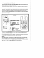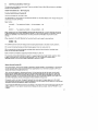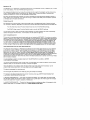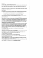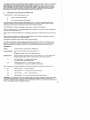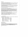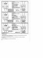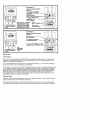
1
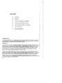
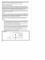
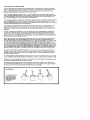
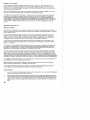
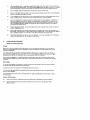
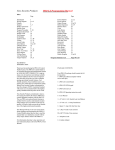
= reJ;)©®frJ~ METAL DETECTOR/TREASURE SEEKER NlETADECir OPERATING INSTRUCTIONS I , CONTENTS A. Assembly B. Batteries C. Programmed Method of Operation D. The Controls And What They Do E. ADC Analytical Method of Operation F. Use In The Field G. Care & Maintenance INTRODUCTION The C-Scope METADEC II is the culmination of many years of research by both electronic engineers and metal detector enthusiasts to produce a detector with high performance, that both a novice or an experienced user can harness to the full, simply and effectively. IMPORTANT To protect your investment complete both sections of the guarantee at the back of this instruction booklet and return the reply paid portion to C-Scope. This is particularly important in order to obtain the free second year parts guarantee. Please retain the original packing box. In the event that your detector should ever require to be serviced. this package will be most suitable for postal protection. C-Soope detectors are recognised as the finest detectors available. They are designed with lasting quality in mind. high technology, and above all, value for money. The only way to realise this value and quality is to carefully study and understand this instruction manual. You will then be able to obtain all of the advantages designed into your detector. It is also strongly recommended that you experiment with the detector's operations indoors in air, with various test samples, in order to learn to identify and understand the detector's capabilities and responses. Always remember that becoming a good metal detective is like becoming a good photographer or fisherman. Although It is an advantage to buy the best equipment having bought it, patience and hours of practice are needed to become proficient. 2 DIAGRAM 1. A. B. C. D. E. F. A. Lower Stem Middle Stem Upper Stem Search Heed Fastener Search Heed Lugs Friction Boot G. H. I. J. K. Knurled Nut lil Knurled Nut (ii) Cable Din Plug Din Socket ASSEMBLY INSTRUCTIONS To assemble the METADEC IIconnect the stems to the search head. First connect the lower stem (Al. which is already inserted into the middle stem (Sl. to the search head. Undo the search head fastener (D) and then carefully position the lower stem between the search head lugs IE) so that the drilled holes in the lugs, the friction boot (F) and the lower stem line up. Insert the search head fastener and tighten by turning the small nut until it is tight. Then by holding the small nut and turning the lever nut over further tighten the fastener. Do not tighten with pliers or tools or the search head lugs may be over-stressed. If the search head becomes loose fitting it may be necessary to obtain and fit a replacement friction boot. These can be obtained free of charge from the Ashford factory. Next slide the metal middle stem about halfway up the plastic lower stem so that metal is at least 15 ems away from the search head. It may be necessary to loosen the knurled nut to adjust the stems, but it is not necessary to detach the knurled nut. At the right point tighten the knurled nut to fix the middle stem onto the lower stem. Each knurled nut (G. H.I has a plastic olive seated inside it which when tightened causes the two pipes to fit tightly together. Finally insert the search head and lower and middle stem into the upper stem IC) after loosening but not detaching the knurled nut. Again tighten the knurled nut at the required height. In practice only this knurled nut will need adjusting for future height adjustment. The search head output is a long grey cable (I) terminating in a five pin DIN plug (J). Carefully loop the cable around the stems ensuring that the cable is not too tight between the search head and the lower stem. Some slack is necessary at this point to enable the search head angle to be adjusted in use. Usually about six loops are sufficient. The 01 N plug has a guide to line up with the 01 N socket (Kl. Carefully insert the DIN plug, and when the pins are correctly aligned and seated correctly, rotate the DIN plug collar until it slides onto the DIN socket, then tighten to lock the plug onto the socket. 3 B. BATTERIES The METADEC II is powered by either: a) 12 HP7 Penlight Batteries (not supplied) in 2 six-pack battery holders (supplied with detector) or b) 2 rechargeable packs (an optional accessory). HP7s are standard batteries and are available from garages, department s~ores, etc. Rechargeable batteries in two packs, together with a charger are available as a C-Scope Accessory. It is advised that to begin with standard HP7s are used. You can then evaluate the sort of use you give the detector and decide whether the investment in rechargeables is justified. Battery life is dependent on many things and is difficult to generalise on. The METADEC II is designed in such a way that the audio discriminate only draws significant extra current when a good object is located. It is certainly recommended that headphones are used as not only does this guarantee better depth penetration. it also extends battery life substantially, because the loudspeaker is by far the greatest drain on the batteries. If HP7 batteries are to be used it is necessary to load these into the penlight battery holders (LI which are supplied with the detector in the battery compartment (M). First undo the battery cover IN) by turning the fastener with a small coin through 90 fastener and releases the cover, which can then be lifted off. 0 • This frees the Load the battery holders ensuring thet the batteries are inserted the correct way round with the + and - signs on the batteries corresponding with those engraved on the battery holders. After inserting the batteries roll them in the holders to make the connection good. Connect the battery holders to the battery leads (PI in the battery compartment again making sure the connection is firm and well seated, and place the holders in the battery compartment. Replace the battery cover by locating the two lugs first, and then pushing the end with the fastener home. It may be necessary to align the fastener before pushing it home. Batteries should not be left in the detector if the detector is stored or not used for long periods, thus avoiding possible leakage and expensive repairs. DIAGRAM 2. L. M. N. D. P. K. U. HS. Din Socket Recharge Socket Headphone Socket Penlight Battery Holders Battery Compertment Battery Cover Fastener Battery Leads. Bmery Check 81 Charging As a guide to battery condition a Battery Check facility is provided. To check the batteries switch on the detector at the ON/OFF Tune Switch (Q) and tune the detector by turning this control clockwise, with the Memory Retune Buttons (vi) or (vii) depressed. Once the detector is set at the central Tune position release the Retune Button and then depress the Battery Check tv) switch. If the needle on the meter swings into the bold red sector the batteries are in good condition. Should the needle not reach this sector of the meter and retain its level, the batteries need replacing. When rechargeable batteries are checked the meter needle will not reach full scale, but will maintain the same Y3 scale reading for the life of the charge. Standard HP7s will discharge gradually, reading full scale when new and at the lower end of the bold red sector when discharged to 6 volts. Sometimes faulty batteries will initially give a good battery check, but will quickly discharge after a half-hour or so of use. When battery voltage falls below the necessary level, symptoms will be: erratic signal, meter signal latching on full, signal drift etc. Always check and replace batteries if these symptoms occur. Rechargeable Battery Charging It is not necessary to remove the recha1"geable packs for recharging. A recharge socket (U) is provided so that the batteries can be recharged in the detector. Normal HP7s cannot of course be recharged. DIAGRAM 3. (I) (ii) (iii) (ivl (vi (vil (vii) Pre-set Ground Auto Tuning Audio Discriminete Meter Discriminet8 StatuI Bmery Check Retune Button / ADC Ground Retune Button / ADC Discriminate R. S. T. Q. Z. Sensitivy Function Switch Discriminate On/Off Tune Ground Exclude 5 C. PROGRAMMED METHOD OF OPERATION After assembly and banery insertion the METADEC II is now ready for operation. The METADEC II is extremely simple to operate, and ,is programmed and designed in such a way that the operator is not required to adjust discriminate or ground exclude levels. All that Is required is to turn the detector ON at the ON/OFF Tune Switch (0) and tune the detector to threshold, as described below, and then programme the mode of operations. Here's how:· Tuning Turn the detector ON at the ON/OFF Tune Control which works in conjunction with the two Retune Buttons (vi) or (viil on the meter console. Hold the memory retune push button down, and rotate the Tune Control clockwise until the meter reaches the central Tune position, and the sound is just beginning to break through. Set this carefully and precisely and then release the memory retune push button. If the Tuning level alters or wanders off tune.do not adjust the TUNE Control. Simply operate the Retune push button which will automatically re·tune the detector to the original selected level. Programme Set - See Diagram 4. , DIAGRAM 4. ,.- f -.., '----' \ \ Programmed M.chod of Operation s.c Controll .. follows: (I) (iii) liv) Pnut Ground Audio Dil4:l'im. Mater Disc:rim. - ON ON ON The StatUI Button (v) will indicate which mod. are engllllad and operational. ~r:-:o::I~ 'O"CI)"'O" I~:=~J I~'M~II~ ~I -;'0:- ~ ,f J j • , • - 1--;:17) ,---, 'I!t' :I~ ...... .~ __ I I,....."... I eLEDON OLEDOFF R. S. Senlltivity - 0 Function/Ground Exclude Either BEACH - Salt wllter or INLAND - Ground mineraliMd I @8ynKjl The detector is now excluding the ground at a pre·set level on one channel and discriminating at a programmed level on the other channel. All metal objects will be indicated by an increase in loudness but rejected objects will cause the meter to fall to the left and the tone frequency to decrease. Accepted targets will conversely cause the meter to rise to the right or remain stationary and the tone frequency to increase. Searching Simply sweep the detector in an are, ensuring the head is level and as close to the ground as possible. Advance half a head length at a time, and ensure the tuning level is correctly set by raising the heed an inch or two, depressing the push button re·tune. and then lower the head and continue. For a more detailed description of the CONTROLS AND WHAT THEY DO. and USE IN THE FIELD read on. but if you follow the programmed method. you cannot go far wrong. · D. CONTROLS AND WHAT THEY DO The controls are divided into two areas. Those on the Main Control Box (W) and those on the Meter Console X (see Diagram 3l. On/Off Tune Switch IQI- See Tuning P.6. Function Switch/Ground Exclude lSI This control selects for the type of site. The METADEC II can be used as a professional BEACH or IN LAND detector even though the ground conditions are totally different. Select either: INLAND - Two positions, G·MAX - 01 and G·MAX - 02 or BEACH - Two positions, G·MAX - 01 and G·MAX - 02 When operating in the PROGRAMMED OPERATION METHOD IC) it is only important to set the FUNCTION SWITCH to either INLAND or BEACH. If the Function Switch is on BEACH, and the detector is operated on an inland site or vice versa, the level of PRE·SET Ground will not be correct. When operated in the ADC Method the Function Switch can be used in two positions: G·MAX - 01 G·MAX - 02 The G·MAX channel is the all metal ground excluding channel and is the same in both positions. 01 is a discriminating channel and discriminates against most iron and small foil. 02 is a second discriminating channel and gives higher levels of discrimination including larger silver foil and pull tabs if required. Each 0 channel is variable by adjusting the Discrimination Level (T). The principle of the ADC method is to search in a ground excluding mode G·MAX, and then after a signal is received switch to a discriminating mode 01 or 02 to analyse the target object (detailed setting up in the AOC mode is described in Section E laterl. Manual Ground Exclude IZ) Ground exclusion, which is the process of eliminating signals caused by mineralisation in the ground can be manually set by ensuring that the Pre·set push button (i) on the meter console is OFF, and tuning the Ground Exclude Control (Zl. After tuning the detector, using ground button (vi) and ensuring that 811 the meter console push buttons are off lcheck status (vI), start with the Ground Exclude control (Z) set at O. Lower the search head to the ground from about 50 cms away. If the meter setting decreases (to the left) as the head is lowered. turn the Ground Exclude Control (Z) anti·c1ockwise gradually and repeat until the meter maintains a central tuned position when lowered to the ground. Conversely, when you lower the search head and the meter signal increases (goes up to the right) turn the ground exclusion control clockwise gradually until the meter's central position is maintained throughout lowering the detector head to the ground. If you engage the PRE-SET Ground (i).any setting of the manual Ground Exclude control will be over ridden, so ensure if you require manual control because the site is unusual, that the PRE·SET is not engaged. 7 Sensitivity (R) The SENSlTl V lTY CONTROL regulates the sensitivity of the detector to drift, instability etc., as well as to metal objects. The recommended starting point is O. By increasing the Sensitivity by tuning this control into the + sector the detector will be more prone to drift, erratic signals, ground interference, etc. Where there is no ground effect or outside inter ference the Sensitivity Control can be operated at higher levels. But when the signal becomes unsteady or erratic, the Sensitivity level should be reduced to obtain a clear, steady tuning threshold. Only when the tuning is constant and steady will the detector operate at the best optimum depth penetration. Pre.set Ground Ii) By operating this mode the level of ground exclude is set to a programmed level of ground exclude for INLAND or BEACH, dependent on where the Function Ground Exclude Control (S) has been set. For INLAND sites, ensure Function Switch is set to one of the INLAND settings. For BEACH sites, ensure Function Switch is set to one of the BEACH settings. The red LED comes on when the pre-set mode is selected. To check whether the mode is operating, operate the Status Retune Button. If the mode is ON the LED will light up. Auto Tuning/Ground (iii This control introduces a permanent signal wash out and makes the METADEC II function as a motion detector. Generally, this mode is not recommended as motion detection does reduce depth penetration and makes pin-pointing more difficult. However, Auto Tuning is very useful on heavily contaminated junk sites, and can be used effectively in conjunction with Low Sensitivity setting (see Diagram 10). It is also useful to engage this mode after an object has been located and the detector is laid on the ground. It gives a guaranteed threshold tuning and ensures that the detector remains correctly tuned, so that the search head can be used to check each portion of excavated ground for the metal object. Audio Discriminate (iii) and meter Discriminate (iv) The levels of Discrimination or Rejection are identical in both modes (Discrimination can be defined as the ability to give a different type of signal for ferrous junk or worthless objects than the signal given by a non-ferrous object). Both these Discriminate Modes are set at such a level, so that depth penetration to coins etc. is good, and discrimination against most iron and silver foil is achieved. A precise level of discrimination is selected to give maximum discrimination, without affecting sensitiVity to coins etc. Pull tabs, large silver foil, or large iron will not be rejected. because the levels of discrimination reqUired to reject these also reduce the depth penetration to certain non-ferrous metals and th in section objects. It is not possible to reject a valuable object with the METADEC II's AUDIO or METER DISCRIMINATION Modes. You should now experiment with various coins, iron and silver foil to test the reaction of the various objects so that you will be able to correctly interpret the signals. Hang the detector over a table so that the search head is not near metal. Set the detector to the programmed levels as described, then pass objects across the search head!. The signal is separated into two channels. One will signal the presence of all metals by giving an increase in loudness. The second is the Discriminate Channel and will function either as a METER DISCRIMINATOR or an AUDIO DISCRIMINATOR or both. In METER DISCRIMINATE - The meter will analyse the object. For a bad object the meter signal will decrease towards the left hand "reject" position. For a good object the meter signal will increase towards the right hand "accept" position or remain still. In AUDIO DISCRIMINATE - The pitch of the sound alters to analyse an object. A decrease in pitch signals a bad object. An increase in pitch or no change signals a good object. Sensitivity (A) The SENSITIVITY CONTROL regulates the sensitivity of the detector to drift. instability etc.• as well as to metal objects. The recommended starting point is O. By increasing the Sensitivity by tuning this control into the + sector the detector will be more prone to drift. erratic signals. ground interference. etc. Where there is no ground effect or outside inter ference the Sensitivity Control can be operated at higher levels. But when the signal becomes unsteady or erratic, the Sensitivity level should be reduced to obtain a clear. steady tuning threshold. Only when the tuning is constant and steady will the detector operate at the best optimum depth penetration. Pro-5et Ground (j) By operating this mode the level of ground exclude is set to a programmed level of ground exclude for INLAND or BEACH, dependent on where the Function Ground Exclude Control (S) has been set. For INLAND sites, ensure Function Switch is set to one of the INLAND settings. For BEACH sites, ensure Function Switch is set to one of the BEACH settings. The red LED comes on when the pre-set mode is selected. To check whether the mode is operating. operate the Status Retune Button. If the mode is ON the LED will light up. Auto Tuning/Ground liil This control introduces a permanent signal wash out and makes the METADEC II function as a motion detector. Generally. this mode is not recommended as motion detection does reduce depth penetration and makes pin-pointing more difficult. However. Auto Tuning is very useful on heavily contaminated junk sites, and can be used effectively in conjunction with Low Sensitivity setting (see Diagram 10l. It is also useful to engage this mode after an object has been located and the detector is laid on the ground. It gives a guaranteed threshold tuning and ensures that the detector remains correctly tuned. so that the search head can be use,d to check each portion of e.xcavated ground for the metal object. Audio Discriminate (iii) and meter Discriminate (iv) The levels of Discrimination or Rejection are identical in both modes (Discrimination can be defined as the ability to give a different type of signal for ferrous junk or worthless objects than the signal given by a non-ferrous object). Both these Discriminate Modes are set at such a level, so that depth penetration to coins etc. is good. and discrimination against most iron and silver foil is achieved. A precise level of discrimination is selected to give maximum discrimination, without affecting sensitiVity to coins etc. Pull tabs, large silver foil, or large iron will not be rejected, because the levels of discrimination required to reject these also reduce the depth penetration to certain non-ferrous metals and thin section objects. It is not possible to reject a valuable object with the METADEC II's AUDIO or METER DISCRIMINATION Modes. You should now experiment with various coins. iron and silver foil to test the reaction of the various objects so that you will be able to correctly interpret the signals. Hang the detector over a table so that the search head is not near metal. Set the detector to the programmed levels as described, then pass objects across the search head. The signal is separated into two channels. One will signal the presence of all metals by giving an increase in loudness. The second is the Discriminate Channel and will function either as a METER DISCRIMINATOR or an AUDIO DISCRIMINATOR or both. In METER DISCRIMINATE - The meter will analyse the object. For a bad object the meter signal will decrease towards the left hand "reject" position. For a good object the meter signal will increase towards the right hand "accept" position or remain still. In AUDIO DISCRIMINATE - The pitch of the sound alters to analyse an object. A decrease in pitch signals a bad object. An increase in pitch or no change signa,ls a good object. In practice the operator concentrates on careful sweeping of the search head in large arcs, keeping the search head near to the ground and level. When a signal is received, the operator can then take the search Iclead away from the influence of the object, hold it steady at the operating height, carefully retune the detector and then carefully re-scan across the object to analyse and pinpoint the object. With practice, this procedure becomes automatic, and various combinations of audio and meter discriminate can be used to fully analyse doubtful objects. If in doubt dig. E. ADC ANALYTICAL METHOD OF OPERATION The METADEC II is really two detectors in one. 1. or 2. A totally programmed detector A full manual analytical ADC detector. The programmed method of operation as described on P. 6. (C) is the recommended method of operation, because it ensures a high level of performance, but there are, however, sites and users requiring full manual control of both ground exclusion and discrimination. The METADEC II is therefore designed to operate as an Analytical ADC detector. There is a Ground Exclude - ALL Metal Mode which is selected on the meter console by depressing the ADC Ground push button (viI. . There is also a Discriminate Mode which is selected by depressing the ADC Discriminate push button (vii). Usually the Ground Mode (vi) is used for general searching, and the Discriminate Mode is used for analysing a target object once it has been located. Alternatively the detector can be used in either mode exclusively. The ADC method relies on the Ground and Discriminate switches (vi) and (vii), and these will not operate if the AUDIO or METER DISCRIMINATION switches (iii) or (iv) are in the ON position. When these are ON, the switches (vi) and (vii) are overriden and become solely retune buttons. ADC Method Tuning Tune the detector as described in Tuning P.6. Ground Exclude Set the Ground Exclude (Z) as described on P.7. or Engage the Pre-Set Ground (i) as described on P.7. Discrimination Select the appropriate mode at the Function Switch (S) - i.e. IN LAND site or BEACH site, and select a level of Discriminate at the Function Switch. Dl No Discrimihate - to average discrimination All metal to iron reject and small foil. D2 Average Discrimination - to Sevp.re Discrimination. Iron and small foil - Large iron, large foil and pull tabs. Each D mode can be raised by adjusting the Discriminatel level of the Discriminate Control (TI. i.e. Dl Discriminate 0 - Dl Discriminate 10 D2 Discriminate 0 D2 Discriminate 10 No Discrimination. Iron and silver foil Discrimination. - As D1 - Discriminate 10. Iron, silver foil and pull tab Discrimination. WARNINGI I f the detector is set to D2 Discriminate 10 as well as rejecting pull tabs, some copper nickel coins and gold rings etc. will be rejected at these severe settings. Copper and solid silver or gold will be detected though. Generally, only set the detector to D2 - lOon sites where the incidence of pull tabs makes detecting impossible otherwise. 9 Sensitivity (R) The SENSITIVITY CONTROL regulates the sensitivity of the detector to drift, instability etc, as well as to metal objects. The recommended starting point is O. By increasing the Sensitivity by tuning this control into the + sector the detector will be more prone to drift, erratic signals, ground interference. etc. Where there is no ground effect or outside inter ference the Sensitivity Control can be operated at higher levels. But when the signal becomes unsteady or erratic. the Sensitivity level should be reduced to obtain a clear. steady tuning threshold. Only when the tuning is constant and steady will the detector operate at the best optimum depth penetration. Once the Ground Exclude Levels and Discriminate Levels have been set the Ground Mode can be engaged by operating the Ground Switch (vi) which also retunes the detector. Commence searching as described on P. 6. If the tuning level varies. reset the TUNiNG by operating the Ground push-button (vii or if this in ineffective. re-set the Ground Exclude level as described on P. 7. When an object has been located and pinpointed, move the detector search head away from the target object. change the mode to DISCRIMINATE by operating the DISCAIM push button (vii); hold the detector head steady. or in contact with the ground itself; ensure the detector is set at the correct threshold tuning level. by again pressing DISCAIM retune push button (vii), and then carefully re-scan the target object. preferably keeping the search head in contact with the ground. to ensure maximum depth and analysis. If the target is accepted the meter will move up the scale to the right. If the target is discriminated against or rejected. the meter will move down the scale to the left. It is possible to operate in the DISCAIM mode continuously, if the ground conditions allow and mineralisation is not severe. by selecting DISCAIM at switch (viiI. in DISCAIM it is best to operate at the lower levels of discriminate, I.e. below 01 - 10. Alternatively, or also, the SENSITI VITY can be reduced at (A) to ensure the threshold Tuning level can be maintained and performance maintained. F. USE IN THE FIELD . The METADEC II can be used in various ways to suit various sites or conditions. For reference a series of diagrams has been prepared to illustrate this. Diagram 5 Diagram 6 Inland Site with Ground Effect. Inland Site with Ground Effect. Method 1. Method 2. Diagram 7 Diagram 8 Beach Site with Ground Effect. Beach Site with Ground Effect. Method 2. Method 2. Diagram 9 All Metal Detection. Method 1. Diagram 10 Diagram 11 Heavily Contaminated site. Heavily Contaminated site. Method 1. Method 2. Recommended Settings Inland Site with Ground Effect If pre-set-ground is off. and all other meter console switches are off and manual ground exclude is set at O. and when the search head is lowered to the ground the signal on the meter falls to the left. then the site has NEGATIVE GAOUND EFFECT caused by iron mineralisation. If when the search head is lowered the signal rises to the right the site has POSITIVE GROUND EFFECT. Set METADEC II as Diagram 5. or 6. ..n If the site has no Ground Effect, when the search head is lowered the meter signal will not fall or rise irrespective of where the manual ground exclude is set. tn this case the Normal Inland Ground setting may be used. This setting causes most normal size iron to be totally ignored. (i.e. There is no negative signal.l Only good objects register. - DIAGRAM 5. Inland Site with Ground Effect Method 1. II Any position, overridden by PRE-8ET GROUND Iil --.L~ Any position overriden by AUDIO and METER DISCRIM. Tune with RETUNE (viI of (viiI depressed 85 per TUNING (P.6.1 When AUDIO or METER DISCRIM are ON th_ bunolll function solely 85 RETUNE BUTTONS and either may be used. One of the Inland Sening.------~~~~~~~~~ DIAGRAM 6. Inland Site with Ground Effect Method 2. II Set as per Manual Ground Exdude (P. 7.1 Any position overriden by AUDIO and METER DISCRIM. ~"f:ptfFqJJ~ Tune with RETUNE lvil or (viii depressed 8S !Jer TUNING (P. 61.~--'I When AUDIO or METER DISCRIM are ON thes8 bunolll function solely 8S RETUNE BUTTONS and either may ba used. One of the Inland Settings -------1: ~==~ Beach Site with Ground Effect Test for ground effect by lowering the search head to the ground as previously described with pre-set ground (j) off. Then either use METHOD 1 or METHOD 2 to overcome this. On a BEACH with varying degrees of concentration of salt water Le. at water edge or above high tide line the ground exclude setting will vary and METHOD 2 is recommended. On a dry beach, there may be no ground effect, but the Ground Exclude should still be set to SALT WATER BEACH. DIAGRAM 7. Beach Site with Ground Effect Method 1. Any position overriden by PRE-8ET GROUND iii II Any position overriden by AUDIO andMETER DISCRIM. --------r"F. Tune with RETUNE (vi) or (viii depressed as per TUNING (P. 6.)--t-+-..:L.. When AUDIO or METER DISCRIM are ON these buttons function solely as RETUNE BUTTONS and either may be used. - DIAGRAMS. Beach Site with Ground Effect Method 2. Set as per Manual Ground Exclude (P. 7.1 Any position overriden by AUDIO and METER ~ ~ ~:;, ~ ~ - '8 - One of the Beach Settings II DISCRIM.-=::"':'::':":"::~_---J.+f?~::HjjJ Tune with RETUNE (vI) or (vii) depressed al per TUNING (P. 6.) When AUDIO or METER DISCRIM are ON these buttonl function solely as RETUNE BUTTONS and either may be used. Must be ,--=======;2-;(1 OFF One of the Beach Settings DIAGRAM 9. All Metal Detaction Either set as per Manual Ground Exclude (P. 7.) or engage PRE-8ET (i) Any polition overriden by AUDIO and METER DISCRIM. ---------H1'71 Tune RETUNE (vI) only depressed as per TUNING (P. 6.) ~~!!!!!:....~" Use (vi) only to TUNE OR RETUNE Do not use (viil INLAND or BEACH or if MANUAL GROUND depending on lite is preferred OFF All Metal Detection If all metals are required to be detected or iron is the target Le. pipe or cable location, do not utilise AUDIO or METAL discriminate liii) and (ivl. Set to BEACH or INLAND depending on the site and use PRE-SET or MANUAL GROUND EXCLUDE to suit. AUTO is recommended for ALL METAL DETECTION. 12 or if Manual Ground Exclude is preferred -OFF DIAGRAM 10. Heavily Contaminated Site Method 1. Any position overriden by AUDIO and METER DISCRIM. Either set as per Manual Ground Exclude (P. 7.1 or engage PRE-5ET iii Sensitivity Low o to -5 Range Tune When AUDIO or METER as per TUNING (P. 6.1 DISCRIM are ON th8S8 buttons function solely One of the 85 RETUNE BUTTONS Inland Settings and either may be used. II DIAGRAM 11. Heavily Contaminated Sites Method 2. Sensitivity LoVlf - - - - . Oto -5 Range II Any position overriden by DISCRIMINATE ---Rf- 10 Tune with RETUNE (vii or (vii) depressed as per TUNING (P. 6.1 01 UI8 or if Manual Ground Exclude is preferred -OFF DISCRIM RETUNE only. General Hints Discriminating When used in the All-metal Mode the METADEC II will detect all metals and will not discriminate. However, in the Meter and Audio Discriminate Modes the METADEC 'I has been programmed to operate at a fixed discriminate setting. It is recommended that all objects that are not rejected should be dug, i.e. if the meter needle does not dip or the audio pitch is inconclusive, dig the object. Iron, unlike a coin, occurs in a multitude of shapes and sizes. As a result it is possible that large pieces of iron may give a positive reading. Iron in the shape of nails or pieces of wire also may be present on the surface of a site. In this case anomalies in discrimination may occur. Anomalies or confusing signals can only occur in the first few inches away from the search head, and are characterised by a double signal from the same object, usually iron, which often ranges from a strong positive to a strong negative signal. To overcome these problems simply raise the search head and re-scan until a clear signal of rejection or acceptance is obtained. Detection Range Detection ranges will vary depending on the size of the object, the length of time an object has been buried. and the type of ground the object is buried in. The best ground conditions are well compacted soils and coins can be found at the greatest depths if the object has been buried for some time and the coin has interacted with the salts in the ground. thereby appearing larger to the detector. The worst conditions for detecting are on loosely compacted or freshly dug ground or when the object has only recently been buried. In these conditions detection range will be reduced. 90% of all artefacts are found within 6" of the surface. N.B. Adverse soil conditions can reduce depth of detection by more than half. Determining the Target Size and Depth An operator who is familiar with his instrument will be able to do an excellent job of determining object size, shape, and depth before he digs. This technique is learned from careful analysis of the audio signals coming from the detector. Each time a signal is heard,listen for any peculiar characteristics it may have, determine over how large an area you get a detector signal, and try to "outline" the object before you dig. Listen for the sharpness or dullness of the signals and determine the magnitude of strength of the signal. A coin for example will have a sharp signal, a nail a fuzzy signal. After digging up the object, compare the object size, shape, depth and position in the ground with signal information you received before digging. After careful analysis of many digs, you will learn to "read" the hidden target before digging. Detecting To test for the type of signal you will get, take a coin or metal object and with the detector set up on a table tuned as previously described, move the metal object towards and across the search head. You will note that the volume will increase quickly as the metal object passes across the search head, with the loudest sound occurring when the search head is immediately centred over the metal object. As the object passes beyond the search head the sound will quickly fade. Since the detectors employ a Total Response search head the object can be detected across the full width, back to front, of the search head. Maximum sensitivity down the middle of the search head. Pinpointing (i) The strongest signal will always be received when the object is directly beneath the centre of the head (see X in Diagram 12). To poinpoint the find, stop the search head when you are directly over the target object, then move the search head through 90° and sweep again, thus forming a cross with the two sweeps as shown in Diagram 12. (ii) To 'focus' the target signal further raise the search head, retuning if necessary, and pass the search head over the object until only a faint signal is heard. The faint signal will then be occurring at point X under the centre of the head (Diagram 12). More accurate pinpointing, particularly of deeply buried objects can be achieved by finding the centre of the target object as described above and fixing its position in the 'minds eye'. Turning your detector through 90° and sweeping across the target again will give a second reading, accurately determining the centre of the object (Diagram 12). . Digging carefUlly at point X will reveal the find. With little practice, size, shape and depth of an article may be estimated in this way before digging. DIAGRAM 12. Plclc ·up A... 14 The Importance of the Right Approach Treasure hunting can be a profitable and rewarding hobby, if approached in a patient and diligent manner. Time spent researching to locate a worthwhile site for a search can be time wasted if your search is hasty and erratic. To achieve maximum results it is important then. to decide on your approach to any particular site in advance of the actual search. Tactics will be decided by the type of site - it is more profitable to scan a small area thoroughly. than to conduct a haphazard search of the total site. However, when the site is too far away for YO\J to make several return visits a plan should be adopted which gives maximum site coverage, at the same time as indicating the most likely areas for detailed search. Your detector alone is not a guarantee of successful treasure hunting. Any detector needs an operator . and for the best results the operator needs the right approach, attitude and technique. Too many beginners neglect the importance of pre-planning and research before using their detector in the field. and patience and technique during the actual search. A successful search should begin with research sometime before the day of the actual search. The extent and thoroughness of your research will be one of the major factors in the success of your detecting. You should aim to get as complete an understanding as possible of the local history and geography. The key to the choice of the site is to think of people. where they congregated over the past few hundred years. What were their customs and pursuits? Where did they spend money? Where did they carry money? The answers are not Homan sites, nOT are they associated with mystic treasure stories of crocks of gold. !Bather, they are unassuming, undramatic places. like public footpaths and ancient rights of way. old houses and so on. When you have chosen your site, allocate a whole day from early morning to early evening for the search. Make sure that you have all equipment you are likely to need. Your detector should be checked before starting out, and you should always carry a spare set of batteries. You will also need a strong, sharp trowel. It is also a good idea to have a set of lines and pins so that you can layout your search area scientifically. Most beginners make the mistake of rushing about hoping to chance upon a rare find. If for example there happened to be a valuable ring that was buriad 4" deep on the site you were searching, if you rushed about haphazardly and quickly on the site, the odds would be very much against your finding it. On the other hand, if you pegged out the area scientifically and searched slowly and thoroughly, the ~ds of finding the ring would be much more in your favour. Remember, BE PATIENT and WOR K SLOWLY. Do not try to cover too large an area. Restrict yourself to a small area and work through it thoroughly. Make a note of the position and extent of the area, and then when you return you can start again further on without missing any ground or covering the same area twice. It is also important to keep the detector head as close to the ground as possible. Ideally. you should "iron" the ground with the search head of the detector, so that you do not lose any detection range. Similarly. if you work slowly and carefully you should be able to distinguish the faint signals as well as the clear·an signals and further increase your finds. The technique of getting the best out of your detector is not learnt overnight. You need to get as much experience as possible so that you can recognise every kind of signal. Indeed. a good detector operator can often tell you what is being detected before it is unearthed. DIAGRAM 13. It is essential that the search head is kept close and paf1111el to tha ground to avoid missing finds as in A, CandD. Sweeping - For Example: For extremely small object searching, such as coins, rings, nuggets, etc. lower the search coil to within one inch of the ground. Sweep the coil from side to side in a straight line in front of you. Keep the coil at a constant height as you sweep from side to side. Move the coil at the rate of one foot per second (see Diagram 131. After you have become familiar with the instrument the sweep rale may be increased to two feet per second. The optimum sweep rate must be determined by each operator. The detector should be held comfortably in the hand, with the coil held as closely to the ground as possible. As the detector is scanned from side to side in front of the operator, the search coil should be advanced approximately two-thirds the diameter of the coil. This keeps the operator moving ahead, and it allows some overlapping of each sweep. This overlapping ensures that nothing will be missed. It is as well to note here that the operator SHOULD NOT RUSH. This is one of the most common mistakes made by detector users. If you rush, you will not adequately cover the ground. Metal Detecting and the Law Rights of the Finder The rights of the finder fall into two distinct classes. The first relates to objects that have recently been lost, and the second to items of gold or silver which are subject, or might be subject, to the laws of the Treasure Trove. In the first place, where the object has been recently lost and found and is valuable, it should be handed to the Police as soon after it has been found as possible. The Police will then attempt to locate the owner. If they succeed in locating the owner, he has the legal right to the object and is not legally bound to reward the finder. That is a matter for the owner's conscience. In the event of the Police failing to locate the owner they will probably return the object to the finder. If, however, the owner makes a claim for the object at a later date, the finder must return the item to the owner. If the owner is not located the finder has the best rights to ownership, provided that the object was not found on private property, in which case the owner of the land often has a better right than the finder. The solution here, of course, is to obtain permission beforehand and to come to some agreement with the landowner with regard to the division of any finds. If on the other hand, the find of gold or silver can be proved to have been deliberately concealed, with a view to recovery at a later date, the find comes under the laws of the Treasure Trove. If the objects cannot be proved to have been deliberately concealed, the find cannot be declared Treasure Trove. Usually this point centres around the quantity of coins in a hoard, or whether the find is in a container. ObviouSly, if there are a hundred or so coins in a pot, they were almost certainly deliberately concealed. If, however, there are only one or two coins, it is more likely that they were lost accidentally. If the objects are declared Treasure Trove, the finder has no need to worry, for he is rewarded with a cash settlement to the full market value of the find. When the objects are not declared Treasure Trove, the owner of the land on which the find was made usually has a better claim to ownership than the finder. In Scotland all newly discovered ancient objects of all metals, whether deliberately concealed or not are subject to the same procedure as Treasure Trove finds in England. Code of Conduct 1. Do not interfere with archaeological sites or ancient monuments. Join your local archaeological society if you are interested in ancient history. 2. Do not leave a mess. It is perfectly simple to extract a coin or other small object buried a few inches under the ground without digging a great hole. Use a sharpened trowel or knife to cut a neat circle or triangle (do not remove the plug of earth entirely from the ground); extract the object; replace the soil and grass carefully and even you will have difficulty in finding the spot again. 16 G. 3. Help keep Britain tidy - and help yourself. Bottle tops, silver paper and tin cans are the last things you should throwaway. You could well be digging them up again next year. Do yourself and the community a favour by taking all the rusty junk you find to the nearest litter bin. 4. Do not trespass. Ask permission before venturing on to any private land. 5. Report all unusual historical finds to the local museum and get expert help if you accidentally discover a site of archaeological interest. 6. If you discover any live ammunition or any lethal object such as an unexploded mine, do not touch it. Mark the site carefully and report the find at once to the local Police. 7. Learn the Treasure Trove laws and report all finds of gold or silver objects to the Police. If a Coroner's inquest finds that the objects were deliberately concealed with the intention of retrieving them, they become the property of the Crown and therefore Treasure Trove. But even if the British Museum decides to exercise its right to keep the property, the finder is granted the full market value. 8. Respect the Country Code. Do not leave gates open when crossing fields, and do not damage crops or frighten animals. 9. Never miss an opportunity to show and explain your detector to anyone who asks about it. Be friendly. You could pick up some useful clues to another site. If you meet another detector user, introduce yourself. You may learn much about the hobby from each other. 10. Remember that when you are out with your detector, you are an ambassador for the amateur treasure hunting fraternity. Do not give us a bad name. CARE AND MAINTENANCE CARE OF YOUR DETECTOR Storage When not in use your detector should be stored in a dry and warm environment. If it is not to be used for a certain length of time it is advisable to remove the batteries to avoid leakage which could cause serious damage. The working life of your detector will be shortened by careless use or neglect of the unit. Th ink of your detector as a scientific instrument NOT A TOY. Your detector is designed to withstand rugged handling on any terrain, but mis-use or lack of due attention will tell in the end. After using your detector in a hostile environment (salt water, sand, etc.) the exterior parts of the casing should be flushed with clean fresh water, paying particular attention to the head, and cal'"efully wiped dry. Salt Damage If you use your detector continually in a salty environment, particularly when the wind is blowing off the sea, salty air can penetrate the control box. Corrosion can occur in vital parts of the delicate electronic circuitry. I t is therefore recommended that precautions such as covering the control box with polythene be taken to avoid damage. The guarantee cannot cover such occurrences and any repairs needed because of salt water or spray will be charged. Detector Not Operating la) Check the condition of batteries under load using meter. (See Battery Check Procedure) (b) Check that the search head is properly attached to the control box via the search head cable connector. (et Interchange batteries and ensure connections are correct and secure. Battery life can vary tremendously between makes, therefore your 'new' batteries may already be insufficiently powerful to run your detector. Oscillating Signal Accompanied by Slight Meter Fluctuetlon (a) Caused most often by outside equipment such as fluorescent lights, taxis, radios, power lines, and other metal detectors working nearby. Intermittent Sound from Speaker lal This could be due to poor battery connections. Ensure they are tight and the batteries are securely clipped into place. lb) Loose search head cable connection - tighten. Ic) Radio transmission from pa!\Sing taxi or vehicle using radio transmitter equipment. The Detector Drifts out of Tune (a) Temperature drift caused by the change in air temperature when a machine is moved from a house or a car into the open. lb) The greater the change in temperature the more the drift, and up to 30 minutes may be needed for the electronic circuitry to acclimatize itself. (c) Sometimes battery drain can cause drift of signal. Replace batteries and this should help to maintain a stable signal. Before returning a detector for repair to C-Scope ensure you have done the following: (a) Read instructions thoroughly. (b) Tried new batteries and checked procedure outlined above. Return detector with letter giving full details of fault. 18