1
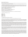
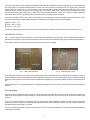
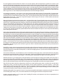
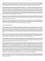
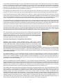
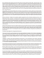
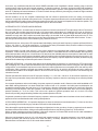
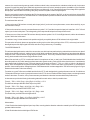
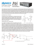
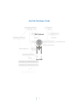
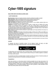
Base Line Testing
ST-70
by David C. Gillespie
as previously published on Audiokarma.org
The Dynaco ST-70 surely must represent the greatest amplification
paradox of all time: It was arguably the best selling power amplifier of all
time, and is arguably the most maligned such device as well. For a
generation who adored it, there have been those in following generations who are quite vocal about it, to the point that the only
useful component they claim it has, is its output transformers. Therefore, it is likely the most modified amplifier of all time as well.
As always however, the vast majority of these claims are solely subjective in nature, with little or no measured performance data
to back up their claims, or to show the improvement a given modification affords to all its ills. Ultimately then, the sales pitch boils
down to the best small lot used car salesman's tactics: Trust me! With so many modification options, and so many new folks
arriving at the doorstep of our hobby daily, the plan of attack in restoring these units can be bewildering to say the least.
I own a rather pristine, early model example of this unit, that I keep as absolutely stock as possible, to allow the unit to act as a
reference against all challengers of its original humble existence. To that point, everything is completely original in my unit
(except for tubes), from the fuse and power cord, to the coupling and power supply caps. At this time, all components are well
within spec, with no leakage or signs of physical age at all. In this day then where the restoration battle cry is "Replace all of it!"
(which I hardly argue against for long term dependability), this unit stands in stark contrast all on its own. Therefore, it serves its
INTENDED purpose for me very well indeed.
I have been asked on numerous occasions to develop an EFB™ modification for this unit (adding to the great pile of
modifications already in existence for it!). Such an effort always starts with baseline testing of a properly operating stock unit, so
as to have a bar set to measure any achievement against. I am offering up my reference example for that purpose here. And
while the purpose of the testing was originally to develop yet another modification for this unit, I thought that with so many, many
other modifications out there -- and all the claims about what you should and shouldn't do to achieve good performance from
this unit -- it would be a good idea to do a reset of the much discussed ST-70, and publish just how good -- or bad -- the original
product really was. Along the way, some of the more popular modifications will be examined as well.
This will include the power supply, output stage, driver board, and overall measured performance as well. Of course, this will all
ultimately be related back to the original goal of developing an EFB™ modification for this unit also. However, of a more general
nature, the results will also serve as a good documented baseline for any and all on their own particular ST-70 journey.
To get the ball rolling then, this was a kit model, and I won the lottery with whomever assembled it. It is neatly built, with the
underside shot almost mirroring the pic provided by Dynaco in their assembly manual as representing a quality build. Those are
the famous "cloth" version of the A-470 output transformers, with everything still clearly being in its original build form.
The tubes supplied with the unit when received were also primarily lotto winners as well, with the output tubes being well
matched pairs of low hour Zenith branded genuine Mullard tubes. The weakest pair of these tubes produced 98% of Average
New NOS Power Output, while the strongest pair produced 102.6% of this value. The worst pair was matched both statically
AND dynamically (i.e. collectively) within 3.65%, while the best pair was matched to within 2.1% under the same criteria. The
two pairs then were matched within 2.55% of each other. Clearly, these are superb tubes to use in a reference Dynaco ST-70.
The driver tubes were also relatively new Zenith labeled un-carbonized 7199s, of unknown (American) manufacture. One of
these tubes has been replaced, for reasons which will be discussed further in the section on the driver board. But clearly, some
one or some tech went through and re-tubed this unit from their Zenith stock before it was placed on the (in)famous auction site
nearly some 5 years ago now, from which I snagged it. The rectifier tube was a brand new JJ GZ34 S. This tube has also since
been replaced (with a very good large bottle Sylvania 5AR4/GZ34 tube), which will be discussed further in the post on the power
supply. Suffice to say however, the tubes now installed in the unit are equally up to every bit of performance that the build and
condition of this unit is, allowing it to represent all that the Dynaco ST-70 was intended by David Hafler to be.
In all then, I have no wish to pile on to any of the popular notions out there, but rather, to let the chips fall where they may
regarding the true performance of the original design, and that of some popular alterations as well.
Measured Stock Performance
While I have individual information on each channel, the information was close enough to simply average the results for
reporting. This also helps to minimize information overload.
1. POWER OUTPUT AND DISTORTION: As measured into 8 ohms from the 8 ohm tap, with the Biaset voltage set for 1.56 vdc
in each channel under stabilized quiescent conditions. The power output figures given are maximum power output levels at the
onset of clipping, while the THD numbers are produced at a power level that is 1 db down from rated power (or about 27 watts) -this to conform to the distortion specifications as provided by Dynaco.
Single Channel -- @ 20 Hz = 39.8W RMS. @ 1 db down, THD = 1.0%
@ 1 kHz = 45.6W RMS @ 1 db down, THD = .18%
@ 20 kHz = 43.5W RMS @ 1 db down, THD = 2.3%
Both Channels -- @ 20 Hz = 31.6W RMS @ 1 db down, THD = 1.9%
Operating @ 1 kHz = 37.5W RMS @ 1 db down, THD = .32%
@ 20 kHz = 34.1W RMS @ 1 db down, THD = 3.3%
2. IM DISTORTION: .45% at 35 watts equivalent power output. .74% with both channels operating.
3. FREQUENCY RESPONSE: (ref 1 kHz)
@ 10 Hz = -.3 db
@ 1 kHz = 0 db
@ 20 kHz = -.25 db
@ 30 kHz = -.5 db
@ 36 kHz = -1.0 db
@ 40 kHz = -1.2 db
4. HUM AND NOISE: 92 db average below rated power
5. STABILITY: No value of capacitance only loading would cause the amplifiers to become unstable.
These figures were all produced with the unit operating directly from the AC line in my home, which was providing its typical
122.0 vac to the unit during the tests. The power output figures were rerun with the unit operating from 117 vac (the published
operating voltage for the unit), which reduced all power output figures by about 2.5 watts. The reduction in line voltage did not
have any significant effect on the distortion levels produced.
Within the results then, they meet the majority of the specifications as presented back in the day, which of course were based on
single channel performance figures -- this because no standard existed for performance presentation at the time. The notable
exception is for the 20 kHz THD figure, and frequency response. To that point, I've never measured an ST-70 that was only .5 db
down at 40 kHz, with the performance my unit shows being somewhat better than typical in my experience. I can only assume
that the specification given then is somewhat optimistic. I have found it is common for ST-70s to show a HF response that is
between 1 and 1.5 db down at 40 kHz, relative to a 1 kHz reference. What is important, is that the frequency response within the
20 Hz to 20 kHz audio bandwidth is flat within .25 db, which is very good, particularly so for equipment of that time -- and
especially so for the level of HF stability achieved.
As for the 20 kHz THD figure, the distortion level produced is typical of that achieved AFTER installation of the HF stability
networks. These networks reduce the open loop gain at 20 kHz, which then increases the distortion produced at 20 kHz due to
the effective reduction of the feedback factor. But they are necessary to produce a practical feedback amplifier that is stable into
varying loads. With these networks lifted in each channel, 20 kHz distortion comes in at an average of .48% at 1 db down from
35 watts RMS power output.
I have always felt that this practice was deceptive relative to the way the specification is given, but have come to the conclusion
that it was accepted practice back in the day none the less. These networks came late to the amplifier design party, after a
number of early feedback amplifier designs were branded as tweeter killers (Heath W-3M for example). The networks were
then added to aid in stability performance, but they caused the HF distortion performance to deteriorate from the specifications
of previous models published without such networks. Therefore, for lack of any better explanation, I can only assume that many
manufacturers continued to publish distortion specifications based on that of the raw amplifier circuit (that is, without the
finished HF stability circuits added) -- likely under the guise of preventing confusion, and certainly of course, to not to have their
product look worse than that of other manufacturers who were following the same practice.
2
In any event, any one of many, many popular amplifiers will exhibit this rising distortion with rising frequency characteristic, with
the Dynaco MK III, numerous Heathkit and Eico models, and many others all clocking 20 kHz THD figures at the specified
power levels well in excess of 2%. Of note however, this is an area where Heathkit really shined, steering very clear of such
simplified ratings, instead, choosing to offer a graph with most models, which clearly shows the rise in distortion at higher
frequencies and high power output levels -- due to the inclusion of these networks. Therefore, it is, what it is, with the distortion
levels produced in the ST-70 at 20 kHz not being indicative of any concern for proper operation.
I did test for low power THD levels, as they can actually rise in some designs from that of higher power output levels. At the
same test frequencies at 1 watt/5 watt levels (again, presented as an average between the two channels):
@20 Hz = .055% / .11%
@ 1 kHz = .035% / .043%
@ 20 kHz = .115% / .50%
This is pretty darn good performance from any vacuum tube amplifier, let alone from a stock 55 year old unit build from a kit!
SQUARE WAVE TESTING:
Fig 1: A 10 kHz square wave at 1 watt into an 8 ohm load looks identical on both channels. The somewhat slanted sides are
indicative of the frequency response figures produced, while the flat wave-top indicates a high degree of damping and stability.
Fig 2: With a capacitor only load, the amplifier is nowhere near becoming unstable.
Fig. 2 Capacitor Only Load
Fig. 1 10KHz Square Wave
For a design of the late 50s, this overall is quite enviable performance, that had other other manufactures scrambling to catch up
to. Most notable was the level of stability produced in light of the other performance levels achieved. That it is a product of David
Hafler is no real surprise, since he was a primary bandleader campaigning for improved stability margins in equipment of that
day.
So, this particular ST-70 is a healthy specimen, making a great platform for reference work, and to make various tests on when
needed.
The Power Supply
As with any stereo amplifier operating from a common power supply, compromises are made, even beyond those compromises
made in the power supplies of mono amplifiers. The question then becomes, how well were those compromises made? We
shall see.
In the ST-70, both channels are powered from the same power supply distribution points. But with channel separation
measured at 58 db at 1 watt, the 55 db Min Channel Separation spec was met handily. So there is no real compromise here, as
the separation figure achieved is very good.
The usual suspect targeted for compromise criticism in the ST-70 is the power transformer, to which could also be added the
rectifier tube, and choke.
3
The case against the power transformer centers on its current capacity, and the temperature it operates at. However, it still
allows its individual per channel power output level to be achieved across the entire audio bandwidth, even permitting it within
the majority of the audio bandwidth with both channels driven. So its current capacity is hardly of the grossly inadequate grade
that some give it. And while the transformer does run warm, it is hardly noted for a failure rate along the lines of say the Heath
series of amplifiers up to and including the W-5M. Therefore, with good dependability, and an ability to allow both channels to
perform well at the same time through out the majority of their rated capability, the compromise this transformer represents was
still a very good one, in view of the price point and performance level the unit sought to achieve.
A much bigger compromise -- in my opinion -- is the use of a single rectifier tube to support a 70 watt amplifier. Competitors with
competing products from the likes of Altec, Fisher, and Pilot all used dual rectifier tubes in their products of similar power levels.
As a result, there is no doubt that the rectifier tube in an ST-70 is the hardest working tube in the chassis, and often will show the
highest failure rate as well -- even when using NOS examples. Which brings us to the new JJ GZ34 rectifier tube that was
installed when I purchased this unit.
Nobody will doubt the bad press this tube has gotten -- and is well deserved of. Some will stand by them, but many more will not.
It being the first such tube I've come across from JJ, I was quite leery of powering the amplifier up when I first got it with this tube
in place. Still, I forged ahead and powered things up, where the tube allowed both channels to bias properly to the correct Biaset
point, and even allowed a brief full power run in both channels at 1 kHz, before I powered things down to prevent a chance of
meltdown. So even though this tube worked -- and worked well for the short test period that I had it in this amplifier -- I wouldn't
trust it in this environment for any kind of long term operation. However, to be fair, this tube has worked perfectly in a lesser
voltage/current environment, where the B+ was under 350 vdc, and the peak current draw was no more than about 180 ma or
so. In any event, with that, the big bulb Sylvania 5AR4/GZ34 was then installed in the Dynaco, which has performed flawlessly
in the ensuing years since then.
Until I performed sustained full power 20 Hz testing with both channels driven that is. Shortly into that test, the Sylvania rectifier
tube buckled and showed its extreme displeasure with this treatment, as signified by a distinct "click" that was heard not only in
the rectifier tube, but also resonated within the power transformer as well. And while it recovered itself gracefully from this single
event (continuing to operate without blowing the fuse), it was a sure indication of how overworked this tube is in the ST-70. And
well it should have protested. Both channels in this scenario were trying to draw at least a combined 500 ma from the tube,
which is well beyond what it is capable of (over twice what it is rated for). Could you imagine what the JJ tube would have done?
Or how about one of the new Dynaco derived 120 watt amplifiers? If the GZ34 can't really handle the full power needs of an ST70, how could it handle one of those beasts? The heavier duty GZ37 handles only precious few more ma, so even it is no real
answer -- even for the ST-70. Even if continuous operation near its maximum rating under normal conditions doesn't send it to
an early grave, any significant hot switching event will. Which all goes to show just how limiting the use of one rectifier tube is in
this amplifier. The unit can get by with one tube for typical use, but it's a definite limiting factor relative to the performance this
amplifier is capable of.
Going SS is an option, but most approaches are fraught with problems. Because I knew the rectifier issue would be a problem in
developing the data for EFB, I purchased a SS plug in replacement rectifier from Triode Electronics to keep things simple. This
is not one of those fancy ones with time delay built in, or with built in dropping devices. It's just some SS rectifiers molded into an
octal tube socket base.
As for the other SS devices, I have heard here on AK of a few failures of the copper units, and the units with built in relay delay
are often prone to producing heavy surges in the output stage, causing accelerated and uneven tube wear, as well as serious
thumps in the speakers when the relays engage. So, the base garden variety plugin SS replacement rectifier got the nod.
With these however, if you simply plug them in and operate the unit from today's line voltage, then initial B+ rises to 525 volts, or
right to the limit of the filter cap voltage rating. This is not particularly a problem for the amplifier portion of the unit (although it
would be a good idea to replace the coupling caps with 600 volt devices in going this route), as the fear of cathode stripping has
been roundly discredited, having no basis with receiving type tubes. But going this route does cause another problem.
Since SS devices have hardly any voltage drop across them, simply replacing them where a rectifier tube was that had a
voltage drop across it causes the peak currents drawn from the power transformer to become elevated -- which gets
transformed into heating in the power transformer. Therefore, whatever temperature reduction you hoped to achieve in the
power transformer by eliminating the rectifier tube, gets counteracted by the increased heating from the increased peak
currents the SS rectifiers create. But there's another basic problem.
Operating this amplifier from a typical 122 volt AC line causes the amplifier tube heaters to operate at nearly 6.8 vac, which is
uncomfortably high at nearly +8%, not to mention that this too is elevating power transformer temperature as well.
A better compromise today, is to do a proper job of installing SS rectifiers, and operate the unit from an appropriate buck
transformer (ideally, 4A minimum).
4
To do a good job of mimicking the voltage drop of a GZ34 tube, there should be a 50 ohm 10 watt resistor installed BETWEEN
the output of the SS rectifiers, and the FIRST filter cap. Installing a resistor at this location will control the peak currents drawn
and improve regulation, providing nearly the same B+ level that a GZ34 would under any condition of operation. Installing a
resistor after the first filter cap, would hurt regulation, and NOT limit the peak currents drawn from the power transformer.
When using this rectifier approach with a buck transformer to provide 117 vac, the initial B+ rises to 500 volts, but then falls to
nearly the same B+ level as produced by a GZ34 in the same scenario, yet is easily able to handle the maximum current needs
of the amplifier without concern. The tube heaters operate from 6.4 vac using a 117 volt line, the bias controls barely need to be
moved from their GZ34 setting, and importantly, using these two expedients cools the power transformer notably. with a buck
transformer, the SS plug in rectifier and dropping resistor installed as described, and the unit biased to Dynaco
recommendations, the hottest point on the power transformer was just 130F in my lab after two hours of high power testing. This
of course was with the cover off, and the ambient temp in here is only 70F, but this is still quite cool operation for the transformer.
The amplifier was graceful under all conditions with this approach, showing no concern over the loss of the rectifier tube. All in all
then, they are improvements worth making to any stock ST-70.
The choke is also somewhat of a compromise, providing good filtering under even medium power conditions, but completely
saturating under conditions of high power output. Still, it does make for a quiet amplifier during normal use, with its high power
limitations covered by the sound level of elevated power output. In any event, it size was a good compromise, helping to achieve
quiet operation of the unit with typical use.
And finally, there's the selenium rectifier. Selenium rectifiers are well known to ultimately fail in high current applications (those
where significant heat is created within the rectifier) JUST AS they are well known to hardly if ever fail at all in very low current
applications, such as the bias supply represents. I would hardly suggest not to replace it from an ultimate durability standpoint,
but to replace it simply because it's a selenium rectifier -- in this application -- has little merit.
The Power Output Stage - Pt. 1
The output stage of the ST-70 harkens back to Hafler's earliest days at Dynaco. His first output transformer -- the A-430, as used
in the inaugural MK II amplifier -- was specifically designed for use with EL34 tubes. With a 4300 ohm primary, and screen taps
placed at 33% of the primary winding, the load the screen tap position was experimentally determined to produce the greatest
linearity from these tubes, coupled with a good degree of load regulation. The A-470 output transformer, as used in the ST-70,
has the same exact specifications, at a somewhat lower power rating. Unlike the original A-430 transformer, the A-470 also
includes a 4 ohm output tap as well -- this to accommodate the 4 ohm speakers (notably AR) that were starting to appear at the
time.
So the ST-70 operates the output tubes with the same loading conditions as Hafler's original amplifier does, but operates them
at a lower B+ level (~410 vdc vrs ~450 vdc) to achieve a lower power output level. Which brings us to the first myth about the ST70's output stage: Lowering the quiescent current level (i.e, Biaset voltage) to extend tube life. From a standpoint of absolutes,
lowering current levels will extend tube life. But in doing so in the ST-70, what is the practical return?
A common battle cry for this practice comes from those who categorically say something like: "Because tubes were so cheap
back then, manufacturers ran the tubes right to the ragged edge for the performance ratings wars, and didn't care about tube
life". No doubt in some cases that's true. But that line is said so often, that the statement has nearly become fact for all cases,
regardless of what the individual facts actually are. So what about in the ST-70?
The 15.6 ohm cathode resistor causes the output stage to operate at 100 ma total cathode current in each channel, when the
Biaset voltage is set for 1.56 volts as instructed. With a matched tube set, this is 50 ma per tube, with about 45 ma of it conducted
by the plate. With 410 volts across the plate and cathode then, this equates to 18.45 watts, which as a percentage of the very
conservative Design Center 25 watt plate dissipation rating for these tubes, equates to operating them at only 73.8% of their
rated dissipation level. Even when operating the amplifier from a 122 volt line and still using the recommended Biaset level, the
dissipation only climbs to 19.4 watts, for 77.6% of rated capability. These are both very conservative levels to operate these
tubes at -- particularly when you consider it is being judged against the Design Center Rating value. The more common Design
Maximum Rating System that was in place at the end of the tube production era rates the EL34 as a 30 watt tube, meaning the
tubes would only be operating at 61.5% of capability (64.7% at high line voltage) under that rating system. With such
conservative operation of tubes that are designed to conduct a continuous 165 ma each (Design Maximum rating) -- both from a
dissipation and current flow standpoint -- backing the quiescent current level down by 10 ma per tube to save on tube life will
gain you precious little of what you are trying to achieve, but it will give you a whole bunch more distortion!
If a THD test set is connected to the ST-70 and each channel is individually driven with a 1 kHz signal to 1 db below the rated
power of 35 watts (about 27 watts), it will be found that the lowest distortion operation point is achieved with a quiescent Biaset
setting of -- you guessed it -- 1.56 vdc, or very close to that setting. If you go below OR above this setting, distortion will climb,
and do so rather rapidly.
5
For example, with a Biaset voltage of 1.40 vdc (45 ma total current flow per tube), 1 kHz THD climbs nearly 55%. If you reduce it
further to 1.25 vdc (40 ma per tube) it climbs another 170%, for a total of 225%! So, reducing the current draw of each tube by
6% of its rated cathode current, when it is already operating at just 30% of rated cathode current and 62% of rated plate
dissipation, all to gain what, 225% more distortion? That is a very poor compromise to make, versus the very well thought out
operating conditions that Hafler set up for the tubes to operate at.
But what about using different tubes? The 6L6 in many of its various forms, manufacturers, and sources, is a popular alternate
for the ST-70. The pin out is the same, but requires slight alterations to the bias supply to bias the tubes at a reasonable value.
Assuming that appropriate bias supply changes were made then, using the popular 6N3C-E Russian derivatives will both
reduce power, and increase distortion, due to the less than ideal loading conditions offered for these tubes. Maximum power
drops to 24 watts RMS per channel at 1 kHz, with both channels driven, while THD rose to .5%. This represents a 36% loss of
power, coupled with a 61% increase in distortion as compared to sockets stuffed with EL34s under the same conditions.
These tubes had a minimum distortion operating point around 50 ma per tube as well. But at this level, these tubes are operating
at nearly 90% of rated plate dissipation capacity, and much more of rated cathode current capacity as well. Additionally, high
power 20 kHz sine waveforms take on somewhat of a triangle waveform at this frequency, with THD running nearly 6% at 24
watts output -- and this at the optimum 50 ma current setting. At 40 ma, distortion at this frequency is nearly 10%.
There are all manner of accolades available in abundance about the sound produced from using 6L6 class tubes, and reduced
quiescent current operation as well. I would never suggest what someone does or does not enjoy in their sonic quests, but I can
say that given the performance intentions that Hafler established for the ST-70, using 6L6 class tubes, and/or reduced
quiescent current levels in place the the designated tubes/setting, will cause it to fall far short of that mark.
Fig. 3 shows show a 20 KHz sine wave at the onset of clipping being squeezed into
somewhat of a triangle formation at elevated power levels when using 6N3C-E tubes.
Distortion of this waveform is ~5.5%. This is invariably due to the lower than optimum
loading conditions being offered to 6L6 class tubes, which are very much happier when
employing a 6600 ohm load, when operating in UL mode.
The Power Output Stage Pt.2: Configuration, A Short History
Speakers. Being basically current operated devices, tubes have a distinct
disadvantage in driving them, since tubes are basically voltage operated devices. This
is where SS designs have a distinct advantage since they too are basically current
operated devices, so the shoes and shoelaces match. For tubes to have a level playing
Fig. 3 6N3C-E
field, they need a transformer to convert their high voltage low current nature, into the
low voltage high current requirements of a speaker. But being a voltage oriented device, tubes have one other disadvantage
that a transformer cannot account for: Resistance -- referred to as Plate Resistance. It can be minimized by circuit design and
output stage configuration, but SS devices have such little internal resistance that they have a huge jump on tubes in this regard
when the load is a speaker.
The ultimate resistance of a given amplifier design then is called its "Internal Resistance", which is the primary element in
determining the Damping Factor of an amplifier. Quality vacuum tube amplifier designs will have an internal resistance of
around 1 ohm, while SS amplifiers will often display an internal resistance of .0xx ohm, many times lower than that of
conventional vacuum tube amplifiers. That is why SS amplifiers have much higher damping factors, compared to their vacuum
tube brethern. So why is this important?
Let's say an amplifier has an internal resistance of 1 ohm. Sonically, using an amplifier with a 1 ohm internal resistance is
effectively the same thing as using an amplifier with 0 internal resistance, but placing a 1 ohm resistor between the amplifier and
speaker. Besides the power loss this creates, there is also a loss in control of the speaker, and both increase as the resistance
increases. From a speaker control standpoint, any resistance (from any means) between the speaker voice coil and the
generator source driving it then, is effectively like placing a spring between the voice coil and the cone.
If an amplifier with 0 internal and external resistance commands the voice coil to abruptly stop -- as in the reproduction of a drum
kick for example -- it will, because the 0 impedance of the amplifier electrically shorts out the output from the voice coil, that
would normally be generated due to it's tendency to want to remain in motion after being excited. So the voice coil stops in our
scenario, but the cone, being connected to the voice coil by a slinky, doesn't. The result is muddy, low definition, BUT
ACCENTUATED bass response in many speakers -- because of the continued, uncontrolled motion of the speaker cone at low
frequencies. The same effect is produced by using a proper speaker (no slinky!), but with internal electrical resistance in, or
externally between the generator source, and the speaker. No wonder then that many find SS amplifiers superior in LF
performance: Not only is there typically more available power, but often, better quality of bass reproduction as well because of
the lower internal resistance they afford. So how does this all relate to the ST-70? We're getting there.
6
Early "high fidelity" designs (think big E H Scott radios) had but one way to operate the output stage: Triode mode. Why? They
were the only tubes that existed at the time. For a vacuum tube configuration, triodes have the lowest plate resistance, and
therefore, make for pretty good devices to drive a speaker. But, they aren't very efficient, so they don't produce very much
power. As a result, speakers had to be large and use horn configurations to have the efficiency required to produce a usable
output. Triodes also have a limited HF response as well. But then early program material didn't have much HF energy
associated with it anyway. But then, technology greatly advanced the efficiency of a tube, resulting in the creation of the
pentode. Pentodes can produce boatloads of power compared to triodes, and have improved HF response, but have a very
high plate resistance, which ultimately makes them rather lousy for for high fidelity reproduction needs all by themselves. But
then, a solution was found.
Applying NFB to pentode based amplifiers offers the solution to the pentode's ills, because it effectively lowers the pentode's
high plate resistance characteristic, with the amount of reduction based on the amount of feedback used (assuming it was well
applied). All of a sudden then, you could have your cake, and eat it too. But of course, human beings being what we are, we
argue (to this day) over which is better: Low power triode operation (with, or without NFB), or high power pentode operation with
lots of NFB. We'll argue over the order of distortion products produced (low order for triodes, higher for pentodes), which triode
is the best triode to use, or even if a pentode connected as a triode really is a triode! Then, Misters Keroes and Hafler showed
up.
With their perfection of tapped screen operation (originally suggested by a Brit), UltraLinear Operation was born. Their
transformer company -- Acrosound -- was the first to offer it to the audio community through their first UL transformer model, the
TO-300. With it, the characteristic of a pentode tube is fundamentally changed. Now, the power, efficiency, and frequency
response of a pentode could be had, along with the low impedance and lower order distortion products of a triode, all in one
neat package. Of course, we're still human beings. So all it really did was give us a third mode of operation to argue over . But I
digress. UL changed audio history. And while good performance was still to be had in smaller amplifiers and receivers with
non-UL operation from a wave of new small power pentodes to come, UL operation (or some form of it) remained the go-to
design for most (but not all) manufactures, when it came to high power high quality audio reproduction, right up to the end of the
vacuum tube era.
All of this is likely old school to many in our hobby, but there are also many newbies coming into it everyday. If they get barraged
with decrees from those who say you must do this or that to the output stage for good sound, but have only little understanding
of basic output stage theory themselves, then they have little ability to know if a given modification is really in keeping with the
audio goals they seek. Which in fact, brings us back to the ST-70. If only for those then, this provides some background as to
why the output stage of the ST-70 was designed as it was, and, what different modification configurations can potentially do to
its performance.
The Power Output Stage Pt.3: Configuration Performance
The previous information on internal resistance and output stage configuration is important to have a basis of understanding as
to how and why various popular modifications to the output stage affect the sound as they do. The common understanding is
that it is tubes themselves that produce a unique sound quality when in reality, it is the interaction of a particular tube's
characteristic with the circuit it is installed in that produces a given sonic quality. Therefore, changing the circuit can have just as
much impact on sound quality as changing tubes can, if not more. Changing the output stage configuration in the ST-70 then is
no different.
FEEDBACK -- Claims are often made how feedback hurts performance, so some modifications result in reduced, or potentially
no feedback at all. Feedback primarily affects frequency response, distortion, and internal resistance. It would take having a
feedback modified unit on the test bench to determine the impact produced on these areas, but suffice to say, that a stock ST70, when operating with the NFB loop disabled, will display an internal resistance of 19 ohms on the 8 ohm tap, and a distortion
of 1.1% at 1 kHz, at 1 db below 35 watts output.
Since amplifier internal resistance can have a significant effect on the sound produced, it needs to be minimized as much as
possible, so that the speaker and amplifier can each be judged on their own merits. After all, when the characteristics of one
component affects the operation of the another, the ability to make an accurate assessment of either then is destroyed.
Besides amplifier internal resistance, the other electrical element that influences speaker damping is the DC resistance of the
voice coil itself, with a typical 8 ohm speaker often having a DC resistance of about 7 ohms or so. With a quality amplifier then, it
is the DC resistance of the speaker itself that primarily determines how effective the electrical damping action is. So what level
of internal resistance should a quality amplifier represent?
For the internal resistance of an amplifier to effectively be a non-factor, it should represent no more than 1/10th the DC
resistance of the speaker. Applying this back to the UL output stage of the ST-70 then, it can be seen that with an internal
resistance of 19 ohms on the 8 ohm tap, some help is needed from a feedback network to reduce this value low enough so as to
remove its influences on the effect of speaker operation. Even if the output stage is configured for the lowest possible internal
resistance (triode), that value (7.8 ohms on the 8 ohm tap) is still plenty high to influence the bass response of most speakers.
7
As a result, any modification that does not include SOME reasonable level of feedback is almost certainly going to color the
sound produced, either by way of its internal resistance, or distortion produced. Therefore, designs that claim that feedback is
not needed due to the use of a UL or triode output stage should be held in question, with regards to accuracy produced. The
stock ST-70 displays an internal resistance of .72 ohms on the 8 ohm tap, effectively removing any coloration it might contribute
due to the effects of internal resistance.
Internal resistance is only one amplifier characteristic that can influence reproduced sound. Like testing for frequency
response, it is typically measured at low power levels. The power response produced over the audio bandwidth is another. But
just as important is the quality of power response produced in the face of a varying load impedance, like that of a speaker. The
configuration of the output stage can have a significant impact on this issue as well.
ALTERNATE OUTPUT STAGE CONFIGURATIONS
TRIODE OPERATION -- As mentioned, the internal resistance of a triode connected ST-70 output stage is about 7.8 ohms on
the 8 ohm tap. Since triodes have the least gain of all output stage configurations, the feedback loop is not as effective in
reducing this down to an acceptable level as when operating in UL. But that's OK, because triodes start with a lower internal
resistance to begin with. With a triode connected output stage, the nominal 20 db of global NFB employed in the ST-70 is
reduced to about 16 db, which is still enough to reduce the overall internal resistance of the amplifier down to about .74 ohm -low enough to effectively remove it from introducing any coloration of sound.
Against this however, is the poorer HF response that triodes display, causing the stock frequency response at 20 and 30 kHz to
go from -.25/-.5 db, to -1.0/-2.25 db respectively. A 10 kHz square wave presentation clearly shows the effects on frequency
response, when the output stage is converted to triode operation.
One major benefit of triode mode however, is the power response curve produced with respect to variations in loading
impedance. Triode mode will produce a flat power response of about 17 watts RMS within the audio bandwidth. But importantly,
as the load impedance swings from 1/2 rated load, to 2X rated load, the available power becomes about 16 watts and 14 watts
respectively across the same frequency bandwidth, while still retaining quite reasonable distortion figures in the process (<.4%
at 1 kHz). So while the triode operation presents challenges in the frequency response department, its ability to handle varying
loads while still maintaining low distortion performance is excellent.
PENTODE OPERATION -- A pentode output stage has the highest internal resistance. So connected, the ST-70 output stage
has a whopping 105.7 ohms of internal resistance on the 8 ohm tap! But pentodes also have the most gain of all output stage
configurations, so the feedback loop becomes more effective in reducing this down to an acceptable level, than with any other
configuration. With a pentode connected output stage, feedback rises to 23+ db, which is still effective enough to reduce the
overall internal resistance of the amplifier down to .82 ohms on the 8 ohm tap, and enough to prevent it from introducing any
coloration of sound.
Pentode operation also causes a rise in HF response, showing +.10, +.25, and +.5 db at 10, 20, and 30 kHz respectively. A 10
kHz sqare wave presentation clearly shows the effects on frequency response, when the output stage is converted to pentode
operation.
At a constant impedance and normal loading, the power response in pentode mode is flat across the audio bandwidth at 35
watts RMS, although distortion is at least double that of either triode or UL operation. And while power and distortion are
acceptably maintained when the load drops to 1/2 of rated value, distortion deteriorates notably at 2X rated load, effectively
becoming a 20 watt amplifier under this condition, with distortion climbing yet another three times over normal loading of
pentode operation (to ~ 2.4% at 1 kHz). This is as much a product of pentode operation itself, as it is the A-470 output
transformer providing marginal loading conditions for pentode operation of EL34s.
So pentode operation produces elevated frequency response, and an acceptable internal resistance level when feedback is
applied, but has increased distortion with a rising load impedance.
ULTRA-LINEAR OPERATION -- UL operation displays a low internal resistance as mentioned earlier (.72 ohms on the 8 ohm
tap), preventing it from introducing any coloration of sound from this characteristic.
Since the amplifier was designed with this output stage configuration from the ground up, frequency response is as is stated in
the Measured Stock Performance, failing to meet published specifications, but still being down only .25 db at 20 kHz.
With a constant impedance and normal loading, a flat power response at 35 watts RMS across the full audio bandwidth is
produced, at the lowest distortion levels of all configurations.
When the load impedance varies by 1/2 or 2X rated load impedance with UL, the power response is very similar to that of
pentode operation (with maximum power at 2X rated load being ~23 watts). HOWEVER, because of the UL connection,
distortion does not climb above .4% at 1 kHz under either condition.
8
Fig. 4: 10 kHz square wave in triode mode.
Fig. 5: 10 kHz square wave in pentode mode.
Fig. 5 10KHz Pentode Mode
Fig. 4 10KHz Triode Mode
Note:
An important point of 2X loading performance with pentode and UL modes is not the actual power drop-off, as that is principally
a function Ohm's Law: The source generator can only develop so much output voltage, so if the load resistance attached to it is
doubled in value, then the power developed must fall off. This is true with any amplifier. The notations of the reduced power were
simply to show what it fell to.
The takeaway points are that with both pentode and UL operation, power was maintained as the load was reduced to 1/2 rated
load, but with pentode mode, the distortion rose notably, and particularly so with the 2X load condition, where as with UL
operation (as with triode), the rise in distortion with either 1/2 load or 2X loading was only modest under either of these
conditions. That the UL connection can basically perform as well as triodes do in this regard, yet do so while delivering pentode
levels of power output, is the real beauty of UL capability.
SUMMARY
While UL and pentode operation produce basically the same power response across the audio bandwidth and with respect to
loading conditions, UL operation ALSO shows the same INsensitivity to distortion with varying load impedance levels that triode
operation does -- while watt for watt, producing the lowest overall distortion of all three output stage configurations. This is the
beauty of UL operation, combining the best that the other two modes have to offer in one package.
In the ST-70 then, UL operation of the output stage with feedback would appear to be the best compromise, considering the
power, distortion, frequency response, and damping factor targeted for the unit. Triode operation can certainly be a viable
alternate configuration, with the advantage of that mode typically producing lower order distortion products, but at a cost to HF
response and power. Pentode operation of the ST-70 would not be recommended with EL34 tubes, although may prove
acceptable with 6L6 class tubes. This was not investigated for this project.
The Driver Board
Of all the criticism leveled at the ST-70, the driver board has surely absorbed the lion's share of it. Critics point to its quality of
parts, topology, lack of adjustments, the tubes it uses, board quality, and so on -- which is really unfair, because when this unit
was introduced, its design was considered state of the art in most of these areas. Today however, parts quality is far superior,
alternate topologies can offer greater consistency of performance, AC and DC balance controls are more important due to
production of lower quality output tubes, other more common and/or in production tubes are easier/more economical to source
for driver duty, and board quality has come light years from where it was in 1959. So there is room for improvement today to be
sure. But based purely on a model of performance CAPABILITY, the original driver board is still a very hard design to beat.
Getting beyond concern for its quality of execution and features then, what design based PERFORMANCE issues are
associated with the original driver board? Well, there are basically only two.
LF OSCILLATION:
Unlike the MK II & MK III designs that predated it, the ST-70 uses a resistor connected between the B+ source and cathode
terminal of the pentode input stage, to provide a measure of fixed bias for this stage to help maximize its gain. Along with this
9
measure, the usual screen bypass cap used in all three models is also connected to the cathode terminal as well, for the same
purpose of maximizing stage gain. While both approaches work well for their intended purpose, the addition of the fixed bias
effort in the ST-70 makes it susceptible to low frequency oscillation (@~ 3 Hz), if specific amounts of low voltage DC is applied to
the input jack. Who would do such a thing? Why early versions of Dynaco's own PAS preamp did!
Dynaco resolved this issue by eliminating the DC from appearing at the output of the PAS, so all was well when the later PAS
edition was used with the ST-70. But it still left the ST-70 susceptible to possible oscillation with other sources that contained low
levels of DC voltage in the signal.
The easiest solution to this is:
1. Remove the two 470K resistors currently at the input jacks. If you do not have replacements, remove them carefully, as you
will reuse them in step 3.
2. Remove the two wires currently connected between eyelets 7 & 17, and their respective input jack. Install two .22 uF 100 volt
caps of your choice in their place. The voltage rating of the caps should be kept low to keep the size small.
3. Reconnect one of the removed 470K resistors directly between eyelets 10 & 17 for the Right channel, and the other between
eyelets 7 & 8 for the Left channel.
4. Install two 1 meg 1/4 watt resistors in the positions originally occupied by the two 470K resistors in the original build.
This procedure effectively places an appropriate coupling cap in series with each input of the ST-70, so that any low level DC
that might be part of the input signal is blocked, and can no longer induce any LF instability.
7199 PERFORMANCE:
This tube was designed near the end of the vacuum tube era, with its primary attribute being reduced hum and noise over that of
similar tubes offered previously, making its use in high fidelity equipment attractive. But experience has shown that different
examples of the 7199 can deliver varying degrees of performance. This is not just between those manufactured from different
tooling, but those within the same tooling production as well.
When I first received my ST-70, I mentioned it had a full complement of new, or nearly new Zenith labeled tubes installed in all
the audio positions, all of which tested excellent/new under dynamic testing. During the final checkout however, I noted that the
right channel had significantly lower THD levels than the left channel produced (~ .75% vrs <.20% at 1 kHz at 1 db below 35
watts). Since all the passive components had already passed muster, I knew it was either a tube problem, or a transformer
problem. It was a tube problem. Swapping the two 7199s between their sockets swapped the THD levels nearly figure for figure
between the channels. Hello inconsistency.
Two other very good 7199s were available and tried in the ST-70, with both producing good performance as well. So while three
7199s produced various levels of good performance in the ST-70, the one Zenith tube was clearly sub par, even though it tested
similar to the others. Therefore, I set up some tests to try and determine what the issue was behind the problem tube.
A chart was set up with the following information gathered from each tube, to look for possible clues:
Tube #1 -- THD = .135%, Ep(p) = 108.9, Eg2 = 31.4, Ek(t) = 117.9
This HH Scott tube provided the LEAST Open Loop Gain.
Tube #2 -- THD = .75%, Ep(p) = 83.0, Eg2 = 23.0, Ek(t) = 95.0
This Zenith tube provided the GREATEST OLG.
Tube #3 -- THD = .21%, Ep(p) = 89.4, Eg2 = 25.5, Ek(t) = 100.0
This Zenith tube provided next to the highest OLG
Tube #4 -- THD = .16%, Ep(p) = 110.9, Eg2 = 30.2, Ek(t) = 120.7
This HH Scott tube provided the next to lowest OLG
Observations:
1. Both Zenith tubes had the highest Open Loop Gain, meaning that the distortion reduction created by the NFB loop would be
greatest with these tubes.
2. Both Zenith tubes also had the highest THD levels.
10
3. As Screen Grid voltage increased between the tubes, OLG decreased accordingly between the tubes, in keeping with theory.
4. The tubes with the most even split of voltage across the plate and cathode resistors and tube (HH Scott), produced the least
distortion.
Recently, some attention has been paid to the basic topology of ST-70 type driver stages, and more specifically, how tolerances
in the screen grid of the pentode section can produce significant changes in its plate voltage, which by way of the direct
coupling, can then bias the triode section into an unfavorable condition.
The use of a large series dropping resistor to supply the screen grid with operating power works to largely overcome this
concern. But still, there are tubes whose tolerances are such that they will still cause the triode section to become over-biased.
With the poor performing Zenith tube having the lowest pentode plate voltage of the bunch, it just may be one of those tubes.
To produce optimum operating conditions, the standard rule of thumb for phase splitter designs is that 1/3 of the B+ supply
voltage should be dropped across each of: (1) the plate load resistor, (2) the tube, and (3) the cathode load resistor. To correct a
tube example that over-biases the triode section, the screen grid voltage of the pentode needs to be reduced, allowing its plate
voltage to rise, causing the bias to be reduced in the triode section, and optimum performance to return.
Accordingly, a variable voltage supply was then added to the screen grid circuit of this tube, allowing the screen voltage to be
reduced even further than it already was. Result? When the adjustment in screen grid voltage was made to properly bias the
triode stage, the THD for this tube did not change one iota from that before the adjustment was made. Zero, Zip, Nada.
Since tackling that symptom didn't provide any resolve for the inconsistency, the next check involved making sure that the driver
stage was supplied with enough B+ during periods of elevate power output, to ensure its capability of providing the output stage
with plenty of low distortion drive signal during those times. Using a variable voltage power supply, the B+ to the driver stage
was varied to see at what point the supply voltage to it impacted the THD produced by the unit. Not until the supply voltage
reached a low of 200 vdc was THD negatively impacted.
So the results from both of these tests would indicate that the elevated distortion produced from the one bad Zenith tube is a
product of that tube itself, with the circuit not contributing to it in any substantial way, and there being no apparent way to readily
correct for the defects of such tubes. This is the most unfortunate aspect of the Dynaco driver board: While its design is capable
of very high performance, the consistency of the tube designed for it varies all over the map. I have found no easy way to
determine which tubes will perform best in this circuit (short of using a THD test set). However, it appears from these tests that
the tubes which inherently drop a similar amount of voltage across the splitter tube and its loads -- without circuit adjustment -seem to perform the best.
So a simple correction can eliminate any concerns for LF oscillations, and 75% of my 7199 tubes perform very well in my
amplifier. In relating a discussion had regarding the design of the power supply to the design of the driver board, and the results
of its design versus the reality of practical use, it does what it needs to do very well. In the finished amplifier, it provides credibly
flat frequency response over the whole of the audio bandwidth, exceptional HF stability, a well damped square wave
presentation with minimal overshoot, and low distortion, assuming a properly performing 7199 tube is installed.
Still, for a variety of reasons mentioned, alternate driver boards may be desirable. The problem is, there is precious little
information on the performance these boards actually produce once installed, against the copious amounts of subjective
information offered about them. All you can do then is to do the best research you can in making a decision as to what is best for
your needs.
Final Summary
The Dynaco ST-70 was designed in an age when high accuracy sound reproduction was THE ONLY goal in high quality, high
fidelity sound equipment, and came to the party with an impressive list of credentials to backup just how well it could accomplish
that. As originally designed, with:
1. A frequency response from 20 Hz to 20 kHz that is flat within .25 db,
2. A power response that will allow full reproduction of the 20 HZ to 20 kHz bandwidth within 1 db of rated power with credibly low
distortion,
3. Ample power to handle virtually any speaker of the day with virtually any source material of the day with ease,
4. Excellent HF stability,
5. Excellent transient response,
11
6. A very good Damping Factor,
7. Relative insensitivity to fluctuations in load, and
8. Credible performance with both channels driven
The ST-70 delivered a ton of performance for very little money, from a young upstart company that had no business producing
such a good product -- all of which made the big boys blink, and set standards that many amplifiers manufactured today could
only dream about achieving.
The biggest failing this amplifier has, is that it was too good for the price. As a result, there were more sold than by any other
product of any other manufacturer -- by quite a large margin -- which is to say then, that it became all too commonplace. Once
that happened, then just like the equivalent of the small block Chevy that it is, everybody and their brother's uncle started
producing modifications to make it "better" at what it's supposed to do.
What's interesting though is that those producing the modifications say it is to address the 70's rather "average" performance,
diminished top end, or weak bass presentation. Some claim the driver stage is "ineffective", and so on, while they all say that
their modification turns the ST-70 into the best amplifier they've ever heard -- but offering precious little evidence to backup their
claims that its performance is actually any "better".
Truth is, many people today have little understanding for just how good the original design really is. With many having little
concern for specifications -- or accuracy for that matter --their ears then become the sole judge, trial, and jury of all things audio
in the creation of good sound.
But the ST-70 wasn't designed to "create" anything at all. If it did, that would mean it was altering the original source in some
way. In fact, ST-70 was designed to create as little as possible on its own, while faithfully REcreating as much of the input signal
as possible, and no more. THAT is the standard by which the original design should be judged.
Likely then, those who feel that a properly operating ST-70 alters or hinders sound may not really be familiar with what truly
accurate sound is at all, but rather, have their own definition of it. However, with nothing to base their definition on, it becomes a
slippery slope when measured data is disregarded, and accuracy becomes solely based on perceived sonic performance -- if
accuracy is to matter at all. Against this, the proven performance capabilities of the original design, and the unmatched sales
record of the ST-70 provides overwhelming evidence for just how well it did in fact accomplish its goals.
That being said however, there are simple things that can help adapt the ST-70's original purpose to today's audio reality:
1. The rectifier tube can be replaced as discussed for more efficient, and cooler operation, and eliminates the exorbitant cost of
NOS and less dependable modern replacement tubes.
2. The line voltage should be adjusted as necessary to maintain the original goal of high performance, coupled with very
conservative operation.
3. As discussed, an input coupling cap should be installed as necessary to prevent the possibility of any dc component within
the signal source from upsetting LF stability.
4. Choose your 7199s carefully. I have found that those employing a carbonized coating on the side of the glass envelope
containing the pentode section to be quite consistent in delivering proper performance.
Beyond these measures then, any modifications changing the active circuitry to alternate designs will likely change
performance capability, both measured, and perceived. That may be your goal which is fine, but if not, realize the possibility
exists.
As for those interested in installing EFB™ in the ST-70, it can be done, and will result in reduced distortion and quiescent
operating currents. But because of how well the ST-70 was originally designed, the gains it will produce will be greatly limited, as
compared to other installations documented, making the return on the effort rather small.
In addition to providing EFB™ action for distortion reduction, previous efforts have also allowed EFB™ to correct for
inappropriate bias configurations used for the loading conditions offered, reduced output tube dissipation levels that were
operating at or very near maximum ratings, or even change operating conditions that were inappropriate for the load conditions
offered. With multiple benefits then, adding EFB™ to those scenarios is highly recommended.
But as the original design of a unit becomes optimized from the get-go, adding EFB™ produces ever diminishing returns -- as it
should. A properly designed amplifier operating from regulated power supplies would not benefit from EFB™ at all.
12
EFB™ is simply a way to achieve virtually all of what regulated power supply operation has to offer with regards to distortion
reduction, with the possibility of correcting other ills along the way as necessary.
In the ST-70, EFB™ would not add extended tube life to speak of, as the operation of the output tubes is already quite
conservative to begin with. It cannot be used to correct for original design ills in the output stage, because they basically don't
exist. It can reduce distortion some, and heat dissipation some, but the distortion levels of the original design -- even with both
channels driven -- is still quite low, and low enough to suggest that EFB™ would not really provide any sonic improvement to
speak of. That leaves reducing heat dissipation levels, which would be reduced more by eliminating the rectifier tube.
I'm hardly trying to trash my own product! But in this case, the ST-70 was so well designed as to benefit only marginally from the
concept.
Those new to an ST-70 then owe it to themselves to first properly restore it to its original configuration, and then listen to it
carefully for an extended period of time. Then, if you are looking for a different kind of sound, so be it. But at least find out what
caused it to outsell everything else by such a remarkable amount to begin with!
13