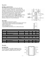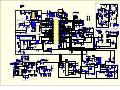
1
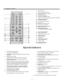
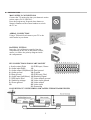
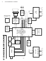
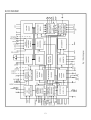
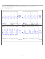
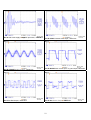
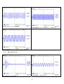
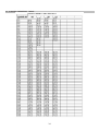
Service Manual
E1 CHASSIS
CONTENTS
o
o
o
o
o
o
o
o
o
o
o
o
PAGE
Safety Instructions
Technical Specifications
Remote Control
Preperations
Operating Your TV
Block Diagram
IC Specs
Pin Voltages of IC’s
OSCILLOSGRAPHS OF SOME IC PINS
Electrical Adjustments
Channel Frequency Tables
Spare Part List
1
2
3
4
5
6
10
11
18
19
22
25
27
1. SAFETY INSTRUCTIONS
GENERAL GUIDELINES
1. It is advised to insert an isolation transformer
in the AC supply before servicing a hot
chassis.
.
the receiver, such as screw heads, aerials,
connectors, control shafts etc. When the
exposed metallic part a return path to the
chassis the reading should be between
4Mohm and the 20Mohm. When the exposed
metal does not have a return path to the
chassis, the reading must be infinite.
2. Potentials as high as 33KV are present when
this receiver is in operation. Operation of the
receiver without the rear cover involves the
danger of a shock hazard from the receiver
power supply. Servicing should not be
attempted by any one who is not competent
with the precautions necessary when working
on the high voltage equipment. Always
discharge the anode of the tube.
LEAKAGE CURRENT HOT CHECK
1. Plug the AC cord directly in to the AC outlet.
Do not use an isolation transformer for this
check.
2. Connect a 2Kohm 10W resistor in series with
an exposed metallic part on the receiver and
an earth, such as a water pipe.
3. Use an AC voltmeter with high impedance to
measure the potential across the resistor.
4. Check each exposed metallic part and
check the voltage at the each point.
5. Reverse the AC plug at the outlet and repeat
each of the above measurements.
6. The potential at the any point should not
exceed 1.4 Vrms. In case a measurement is
outside the limits specified, there is the
possibility of a shock hazard, and the receiver
should be repaired and rechecked before it
is returned to the customer.
3. When servicing observe the original lead
dress in the high voltage circuits. If a short
circuit is found, replace all the parts which
have been overheated or damaged by the
short circuit.
4. Always use the manufacturer’s replacement
safety components. The critical safety
on the
components marked with
schematics diagrams should not be replaced
by other substitutes. Other substitute may
create the electrical shock, fire or other
hazards. Take attention to replace the
spacers with the originals. Furthermore where
a short circuit has occurred, replace those
components that indicate evidence of
overheating.
HOT CHECK CIRCUIT
AC-Voltmeter
TO INSTRUMENTS
5. After servicing, see that all the protective
devices such as insulation barriers, insulation
papers,
shields
and
isolation
R-C
combinations are correctly installed.
EXPOSED
Water pipe
(earth)
METALLIC PARTS
2 K Ohm
6. When the receiver is not being used for a
long time of period of time, unplug the
power cord from the AC outlet.
Figure 1
7. After servicing make the following leakage
current checks to prevent the customer from
being exposed to shock hazard.
LEAKAGE CURRENT COLD CHECK
1. Unplug the AC cord and connect a jumper
between the two prongs of the plug.
X-RAY RADIATION WARNING
The primary source of X-ray radiation in this receiver
is the picture tube. The chassis is specially
constructed to limit X-ray radiation. For continued Xray radiation protection, replace the tube with the
same type of the original one.
2. Turn the receiver’s power switch on.
CAUTION
AFTER REMOVAL OF THE ANODE CAP, DISCHARGE THE
ANODE OF THE PICTURE TUBE AND THE ANODE CAP TO
THE METAL CHASSIS, CRT SHIELD, OR THE CARBON
PAINTED ON THE CRT WITH A HIGH VOLTAGE PROBE
3. Measure the resistance value with an
ohmmeter, between the jumpered AC plug
and each exposed metallic cabinet part on
2
AND MULTIMETER (SELECT VDC) AND THEN SHORT
2. TECHNICAL SPECIFICATIONS
CIRCUIT DIRECTLY TO DISCHARGE COMPLETELY
.
Power source:
220-240V AC, 50-60Hz
Power consumption (nom.) :
40 W
50 W
Standby power consumption :
4W
Aerial impedance :
75Ohm, coaxial type
Receiving system 1:
PAL BG
PAL SECAM BG
PAL SECAM BG DK
PAL I
Receiving channels:
VHF BAND I
VHF BAND III
CABLE TV
UHF BAND
Audio outputs :
2.0W RMS at %10 THD
2.5W RMS at %10 THD
High Voltage :
23 ± 0.5 KV
25 ± 0.5 KV
Focus voltage :
%25.6 ± %38 of EHT
Grid 2 voltage :
0-1400 V
Heater voltage :
6.2 ± 0.2 Vrms
Video/Audio Terminals :
AV1 IN
14”
20”, 21”
CH2-4
CH5-12
S1-41
CH21-69
14”
20”, 21”
14”
20”, 21”
AV1OUT
AV2 IN (RCA, optional)
Operating temperature :
0-45 Degrees
Safety :
IEC 65 /BS P2N
X-Ray radiation :
ACC. IEC 65/BS P2N
1
Video : 1 Vpp,75 Ohm
Audio : 0.5 Vrms, >10 Kohm
RGB
Video : 1 Vpp, 75 Ohm
Audio : 0.5 Vrms, <1 Kohm
Video : 1 Vpp, 75 Ohm
Audio : 0.5 Vrms, >10 Kohm
: TV set is produced to receive “one” of these colour and sound systems.
3
3. REMOTE CONTROL
.
1.
2.
3.
4.
5.
6.
7.
8.
9.
10.
11.
12.
13.
14.
15.
16.
MUTE button
Ten key program button
Two digit program button (-/--)
MENU button
Program up button
Volume decrease button
Return to selected programme button (SWAP)
Information button (i)
STAND-BY button
AV-TV selection button
OK button
Volume increase button
Program down button
16:9 picture format button
Sleep timer button
Normalization button
For Teletext Function (Opt.)
1.
2.
3.
4.
5.
6.
7.
8.
9.
10.
11.
Yellow fastext button
Blue fastext button
Teletext/TV select button
Enlarge button
UPDATE button
MIX button
Green fastext button
Red fastext button
STOP button
SUB-PAGE button
REVEAL button
Special features
•
•
•
•
•
•
•
•
•
•
•
•
Automatic Programming
100 Programme Memory
Available for Cable Channels (A decoder may be
required)
Manual Fine Tuning
Skipping back to the last channel you have
started to zapp via only one button(SWAP).
16:9 picture format
Scart Socket: Video cassette recorder, satellite
receiver, video disc player, DVD, TV games or a
home computer can be connected to this AV
socket with an appropriate connecting cable.
Normalization system to recall the setting in
memory after the colour, contrast, brightness
setting have been changed.
Automatic Volume Limiting.
Infrared Remote Control.
Your TV will automatically switch off if it’s been
programmed from 15 to 120 minutes.
•
•
•
•
•
•
•
•
•
•
•
•
•
Automatically switch to Stand by five minutes
after a channel ceases to transmit.
Multi language menu system
Naming the channels (Automatic with ATS).
NTSC playback.
S-VHS via Scart.
ATS: Automatic Tuning System with country
selection (*).
Audio/Video RCA sockets (*).
Headphone socket (*).
Teletext reception (*).
Zapping (*).
I.P.S.: Intelligent Programme Switch: You can set
your TV to skip to a specific
Channel at a specific time. It works also as an
alarm function (*).
Childlock (*).
Please Note: Zapping, I.P.S., Childlock are
optional if ATS exists.
(*): These features are not available in all models.
4
4. PREPARATIONS
.
MAIN SUPPLY CONNECTIONS
Connect the TV mains plug into your domestic mains
socket outlet (230 V 50Hz AC).
Press the Program up, Program down button or
Numeric Buttons on the remote handset to switch
the TV on.
AERIAL CONNECTION
Using a 75Ω aerial lead connect your TV to the
aerial outlet in your home.
BATTERY FITTING
Insert the 2 AAA Batteries supplied into the
compartment on the rear of the remote control,
ensure you follow the polarity diagram inside
the compartment.
4
4
PIN CONNECTIONS FOR SCART SOCKET
1- Audio output Right
11- RGB input, Green
2- Audio input Right
123- Audio output Left(Mono)13- Red ground
4- Audio ground
14- Ground
5- Blue ground
15- RGB input, Red
6- Audio input Left(Mono) 16- Blanking Signal
7- RGB input, Blue
17- Video output ground
8- Switching voltage
18- Video input ground
9- Green ground
19- Video output
1020- Video input
21- Screening
CONNECTING TV WITH VIDEO AND SATELLITE/DIGITALRECEIVER
5
.
5. OPERATING YOUR TV
A. ZAPP FUNCTİON (OPTİONAL)
D. TUNING THE TELEVISION
Select the programme you would like to recall
by pressing SWAP button. Selected programme
number will appear on the upper left side of the
screen.
Watching
any
programme, you can recall the
selected one by pressing SWAP
button again. If you press SWAP
button again, you can recall the
last programme you
watched. You can cancel ZAPP function by
pressing INFO button.
There are two ways of tuning your television:
• Manual, where you control the tuning process
or Autoprogram where the television does it all
automatically.
• The TV sets equipped with ATS (Automatic
Tuning System) sorts the channels regarding
the broadcasting system of your country
(optionally).
Please Note
If the TV is set to a channel with no signal the
TV will return to standby after 5 minutes. The
time remaining is displayed on the screen.
Manual Tuning
Tuning the TV is accessed through the SETUP
menu.
B. SWAP FUNCTION
To access the SETUP menu:
Press the MENU button twice. SETUP Menu
will appear.
Allows you to swap between the program you
are watching and the
last selected program. i.e. If you
were watching Program 1 and
change to Program 11, press the
SWAP button to go back to
Program 1. Press it again to return to Program
11.
Note: If Zapping function is available SWAP
function will not work.
a) If you don’t know the channel
number (Tuning with SEARCH
function).
Enter the SETUP menu by pressing MENU
button twice.
C. INFO
By pressing the “WHITE (i)” button the
programme number and programme
name (if it is exist) will appear on the
screen.
This
will
disappear
automatically after a few seconds.
In the SETUP Menu select
PROGRAM NO and change to P1
using the Program down button to
select it and the Volume up or
Volume down button to change it.
6
Enter the desired program number
by using the Ten key program
buttons
Use the Volume up/down buttons to
select the program number.
Starting with Program P1, tune in the first
channel as follows:
Use the Program up button to select
SEARCH.Press the Volume up or
Volume down button to start the
tuning search. The search arrow will
appear. When the search finds a
strong searching. The picture will
appear, channel signal it will stop.
Use the Program down button to
select STORE. Press the OK button
and STORED will appear
on the STORE line. The channel will
be stored with the program number
you desired.
Identify which channel you are
watching (BBC 1, ITV 1 etc.) and decide which
program number you want it to be.
You have now stored the first
channel.
Use the Program up button to select
again CHANNEL and continue the
tuning procedure until you have
tuned in all the programmes you
want or the television can receive.
Use the Program down button to
select PROGRAM NO.
Use the Volume up/down buttons to
select the program number.
Use the Program down button to
select STORE. Press the OK button
and STORED will appear on the
STORE line.
To exit the SETUP menu press the
TXT button.
Please note
The system will displayed automatically on
SYSTEM row i.e.BG, L, I, DK depending the
receiving broadcasting system of the country. In
some countries the broadcasting system can be
both in BG/DK or BG/LL´.Only the TV sets
produced with Pal Secam BG/DK or Pal Secam
BG/LL´ systems can receive both BG/DK or
BG/LL´ broadcasts.
Please note
If you do not press any buttons for 15 seconds
the TV will exit the menu system.
You have now stored the first
channel.
Use the Program up button to select
again SEARCH and continue the
tuning procedure until you have
tuned in all the programmes you want or the
television can receive.
b) If you know the channel number. (Tuning
with channel numbers)
Press the OK button to select “S” for
cable channels and “C” for terrestrial
broadcast.
Automatic Tuning (Autoprogram)
Enter the SETUP menu as before.
Use Volume up/down button to
select the channel number or enter
the channel number using the
Numeric buttons.
Use the Program down button to
select PROGRAM NO.
7
Use the Program down button to
select AUTOPROGRAM and press
the OK button.
• Picture Menu
To reach the picture menu press one time
to MENU button.
BRIGHTNESS
CONTRAST
COLOUR
SHARPNESS
Please Note:
a) On the TV sets equipped with ATS a
COUNTRY SELECTION menu will appear.
To change, for example, the colour,
select it using Program down
buttons.
Select the desired country using Program and
Volume buttons.
Press the OK button to select the country and
press the OK button again the Automatic Tuning
System regarding the broadcasting system in
the desired country.
Use the Volume up and Volume
down buttons to change the setting.
To save your settings, select STORE
and press the OK button. STORED
will be displayed.
b) On the TV sets without ATS pressing the OK
button starts AUTOPROGRAM.
When you are sure the aerial is
connected properly press the OK
button and to confirm it press OK
button again.
Note:
If you play NTSC formatted tape from the scart,
the TINT menu will appear to adjust the TINT
level.
To cancel Autoprogram whilst it is
working press the Menu button. As
Autoprogram stores a channel it will
appear briefly on the screen.
• Set up Menu
Set up menu is explained above, under “Tuning
the Television” topic
Your TV is now tuned and ready to use
• Features Menu
E. TV SET UP
To reach the feature menu press three times to
MENU button.
The TV set up is accessed through a menu
system.
Once you have stored your set up, this is the
set up the TV will default to when you switch it
on.
Please note
If you do not press any buttons for 18-19
seconds the TV will exit the menu system.
a) Sleep Timer
The sleep timer automatically switches the set
to stand-by after the preset time has elapsed.
There are three menus;
• Picture Menu
• Setup Menu
• Features Menu
You can select the time from 15 to 120 minutes
with 15 minutes steps.
There are two ways to set the sleep timer;
8
1- Select the SLEEP TIMER in the FEATURES
menu. Select the desired time by using Volume
down or Volume up buttons.
2- You can also use the YELLOW ( ) button on
your remote control to select this function. You
can increase the switch off time interval by
pressing this button repeatedly.
d) Language
There are many languages available for the On
Screen Displays (OSD).
In the features menu select
Language by program down button.
Notes:
The last 60 seconds of the desired switch off
time by counting from 59 down. When this time
interval has elapsed the set will switch to
STAND-BY.
To view the remaining sleep time, press
YELLOW ( ) button. To cancel the sleep time
select OFF in SLEEP TIMER.
Press the OK button to select the language list.
Press the Program up/down or
Volume up/down buttons to page
through all the languages and OK to
select.
b) On Timer
You can select the on time between 30 minutes
to 12 hours by pressing numeric buttons or AV
button.
If TV is at Stand-by position, you can switch it
on at desired time and programme by activating
the ON TIMER feature.
To cancel the on time select off in ON TIMER.
c) AVL
TV transmitters have different sound levels.
AVL (automatic volume limiting) maintains the
same sound level as you switch from program
to program.
From the features menu you can select AVL
button by pressing Program down button.
To supply this press Volume up or down button
and select ON for AVL.
9
IF1 IF1
TDA 16846
IC 601
220V AC in
SCL SDA
115 V
33 V 12.5 V 3.3 V
POWER SUPPLY
AGC
IC 104
TDA 9830
AM DEMOD.
EEPROM
IC 103
24CO8AN
10SI-2.7
AM OUT
51/52/53
28
VERTICAL DEFL.
IC 501
TDA 8357
34
33
TDA 9345
Tvsignal
processor- 8
23
24Teletextdecoder
46
3 with embedded47
2
Controller 48
27
IC 101
6/7
5
B
G
R
AOUT
8
T701, T702,
T703
CRT MODULE
T704, T705,
T706
H-SYNC
H-OUT
HORIZONTAL
DEFLECTION
2SD2599
AV SEL/C-VBS/AUD
POWER AMP.
IC 301 TDA 2822
MUTE
10
AOUT
44
TUNER
IR RECEIVER
VDR A
KEYBOARD
VDR B
10
VGUARD
SCART
R
B
G
EHT
45 V
12 V
FBT
TR 501
107 V
8V
SCART/FRONT AV
SWITCH
IC 201
HEF 4053
5V
V
A
6.
BLOCK DIAGRAM OF E1 CHASSIS
.
.
7. IC DATASHEETS&SPECS
TDA 9345
GENERAL DESCRIPTION
The various versions of the TDA9345 and TDA9345 PS-N3 combine the functions of a video processor
together with a µ-Controller, a Teletext decoder and US Closed Caption decoder. The Teletext decoder
has an internal RAM memory for 1 page(TDA 9345) or 10 page(TDA 9346) text. The ICs are intended
to be used in economy television receivers with picture tubes up to 100°. The ICs have supply voltages
of 8 V and 3.3 V and they are mounted in an SDIP-64 envelope. The features are given in the following
feature list.
FEATURES
• RGB control circuit with ‘Continuous Cathode
a) TV processor
Calibration’, white point and black level off-set
adjustment so that the colour temperature of the
• Multi-standard vision IF circuit with alignmentdark and the light parts of the screen can be
free PLL demodulator
chosen independently.
• Internal (switchable) time-constant for the IFAGC circuit
• OSD/Text gain reduction control
• Horizontal synchronization with two control
• The mono intercarrier sound circuit has a
loops and alignment-free horizontal oscillator
selective FM-PLL demodulator which can be
switched to the different FM sound frequencies
• Vertical count-down circuit
(4.5/5.5/6.0/6.5 MHz). The quality of this system
• Vertical driver optimized for DC-coupled
is such that the external band-pass filters can
vertical output stages
be omitted.
• Low-power start-up of the horizontal drive
• Source selection between the ‘internal’ CVBS
circuit
and an external CVBS or Y/C signal
• Macrovision keying possibility for horizontal
• Integrated chrominance trap circuit
synchronisation.
• Integrated luminance delay line with
adjustable delay time
b) µ-Controller
• Picture improvement features with peaking
• 80C51 µ-controller core standard instruction
(with switchable centre frequency, depeaking,
set and timing
variable positive/negative overshoot ratio and
• 1 µs machine cycle
video dependent coring) and blue- and black
• 32 - 64Kx8-bit(TDA9345) or 64-128Kx8stretching. All features are available for CVBS,
bit(TDA9346) late programmed ROM
Y/C and YPBPR signals.
• 3Kx8(TDA9345)
or
12Kx8(TDA9346)-bit
• Integrated chroma band-pass filter with
Auxiliary RAM (shared with Display)
switchable centre frequency
• Interrupt
controller
for
individual
• Only one reference (12 MHz) crystal required
enable/disable with two level priority
for the µ-Controller, and the colour decoder
• Two 16-bit Timer/Counter registers
• Multi-standard colour decoder with automatic
• One 16-bit Timer with 8-bit Pre-scaler
search system
• WatchDog timer
• Internal base-band delay line
• Auxiliary RAM page pointer)
• Indication of the Signal-to-Noise ratio of the
• 16-bit Data pointer
incoming CVBS signal
• Stand-by, Idle and Power Down modes
• A linear RGB/YUV/YPBPR input with fast
• 14 bits PWM for Voltage Synthesis Tuning
blanking for external RGB/YUV sources. The
• 8-bit A/D converter
synchronisation circuit can be connected to the
• 4 pins which can be programmed as general
incoming Y signal. The OSD signals are
I/O pin, ADC input or PWM (6-bit) output
internally supplied from the µ-Controller
decoder.
11
c) Data Capture
• Automatic selection between 625 WST/VPS
on line 16 of VBI
• Real-time capture and decoding for WST
Teletext in Hardware, to enable optimized µprocessor throughput
• Automatic detection of FASTEXT transmission
• Real-time packet 26 engine in Hardware for
processing accented, G2 and G3 characters
• Signal quality detector for video and WST/VPS
data types
• Comprehensive teletext language coverage
• Full Field and Vertical Blanking Interval (VBI)
data capture of WST data
• Data Capture for US Closed Caption
• Data Capture for 525/625 line WST, VPS
(PDC system A) and Wide Screen Signalling
(WSS) bit decoding
• Automatic selection between 525 WST/625
WST
• In the 10 page versions inventory of
transmitted Teletext pages stored in the
Transmitted Page Table (TPT) and Subtitle
Page Table (SPT)
• Text memory for 1 or 10 pages
• Cursor
• Special Graphics Characters with two planes,
allowing
four colours per character
• 32 software redefinable On-Screen display
characters
• 4 WST Character sets (G0/G2) in single
device (e.g.
Latin, Cyrillic, Greek, Arabic)
• G1 Mosaic graphics, Limited G3 Line drawing
characters
• WST Character sets and Closed Caption
Character set
in single device
d) Display
• Teletext and Enhanced OSD modes
• Features of level 1.5 WST and US Close
Caption
• Serial and Parallel Display Attributes
• Single/Double/Quadruple Width and Height for
characters
• Scrolling of display region
• Variable flash rate controlled by software
• Enhanced display features including
overlining,
underlining and italics
• Soft colours using CLUT with 4096 colour
palette
• Globally selectable scan lines per row
(9/10/13/16) and
character matrix [12x10, 12x13, 12x16 (VxH)]
• Fringing (Shadow) selectable from N-S-E-W
direction
• Fringe colour selectable
• Meshing of defined area
• Contrast reduction of defined area
12
13
TDA 8357J
GENERAL DESCRIPTION
The TDA8357J is a power circuit for use in 90° and
110° colour deflection systems for 25 to 200 Hz field
frequencies, and for 4 : 3 and 16 : 9 picture tubes. The IC
contains a vertical deflection output circuit, operating as a
high efficiency class G system. The full bridge output
circuit allows DC coupling of the deflection coil in
combination with single positive supply voltages.
The IC is constructed in a Low Voltage DMOS (LVDMOS)
process that combines bipolar, CMOS and DMOS
devices. DMOS transistors are used in the output stage
because of absence of second breakdown.
FEATURES
• Few external components required
• High efficiency fully DC coupled vertical bridge outputcircuit
• Vertical flyback switch with short rise and fall times
• Built-in guard circuit
• Thermal protection circuit
• Improved EMC performance due to differential inputs
SYMBOL PARAMETERS
Supplies
Vp
Supply voltage
VFB
flyback supply voltage
Iq(P)(av)
average quiescent supply current
Iq(FB)(av)
Iq(FB)(av)
Ptot
total power dissipation
Inputs and outputs
Vi(p-p)
input voltage (peak-to-peak value)
Io(p-p)
output current (peak-to-peak value)
Flyback switch
Io(peak)
maximum (peak) output current
Thermal data; in accordance with IEC 60747-1
Tstg
storage temperature
Tj
junction temperature
CONDITIONS
during scan
during scan
t ≤ 1.5 ms
TDA 2822
DESCRIPTION
The TDA2822 is a monolithic integrated circuit in
12+2+2 powerdip, intended for use as dual audio
power amplifier in portable radios and TS sets.
14
MIN.
TYP.
MAX
UNIT
7.5
2 x VP
-
12
45
10
-
18
66
15
10
8
V
V
mA
mA
W
-
1000
-
1500
2.0
mV
A
-
-
± 1.2
A
-55
-
-
+150
+150
ºC
ºC
HEF 4053B
DESCRIPTION
The HEF4053B is a triple 2-channel
analogue multiplexer/demulti plexer with a
common enable input (E). Each
multiplexer/demultiplexer has two
independent inputs/outputs (Y0 and Y1), a
common input/output (Z), and select inputs
(Sn). Each also contains two-bidirectional
analogue switches, each with one side
connected to an independent input/output
(Y0 and Y1) and the other side connected
to a common input/output (Z). With E LOW,
one of the two switches is selected (low
impedance ON-state) by Sn. With E HIGH,
all switches are in the high impedance
OFF-state, independent of SA to SC.
VDD and VSS are the supply voltage
connections for the digital control inputs
(SA to SC and E). The VDD to VSS
range is 3 to 15 V. The analogue
inputs/outputs (Y0, Y1 and Z) can swing
between VDD as a positive limit and
VEE as a negative limit. VDD−VEE may
not exceed 15 V. For operation as a
digital multiplexer/demultiplexer, VEE is
connected to VSS (typically ground).
15
TDA 9830
TV sound AM-demodulator and audio source switch
SYMBOL
IFIN
n.c.
CAGC
CREF
n.c.
AMOUT
AMIN
AFOUT
EXTIN
SWITCH
Vp2
MUTE
GND
Vp1
n.c.
IFIN
PIN
1
2
3
4
5
6
7
8
9
10
11
12
13
14
15
16
DESCRIPTION
sound IF differential input signal
not connected
AGC capacitor
REF voltage filtering capacitor
not connected
AM demodulator output
input signal (from AM) to audio switch
output signal from audio switch
input signal (from external) to audio switch
switch input select control
supply voltage +12 V (alternative)
mute control
ground (0 V)
supply voltage +5 to +8 V
not connected
sound IF differential input signal
16
8. PIN VOLTAGES OF IC’s
SYMBOL
IC101(TDA 9345)
TV signal processor-Teletext decoder with embedded Controller
DESCRIPTION
V DC(*)
PIN SYMBOL
DESCRIPTION
1
P1.3/T1
port 1.3 or Counter/Timer 1 input
2,46(2,4)
33
HOUT
2
P1.6/SCL
port 1.6 or I2C-bus clock line
4,88(0)
34
FBISO
flyback input/sandcastle output
0,41(0)
3
P1.7/SDA
port 1.7 or I2C-bus data line
4,88(0)
35
AUDTEXT
external audio input
3,71(-0,06)
4
P2.0/TPMW
0,30(0)
36
EHTO
EHT/overvoltage protection input
1,72(0)
5
P3.0/ADC0/PWM0
0,15(3,22)
37
PLLIF
IF-PLL loop filter
2,45(0)
6
P3.1/ADC0/PWM1
2,48(0)
38
IFVO/SVO
IF video output / selected CVBS output
3,05(0)
7
P3.2/ADC0/PWM2
1,65(1,62)
39
VP1
main supply voltage TV processor
8,12(0)
8
P3.3/ADC0/PWM3
0(0)
40
CVBS1
internal CVBS input
3,79(0)
9
VSSC/P
0(0)
41
GND
ground for TV processor
0(0)
10
P0.5
0(2,72)
42
CVBS/Y
CVBS3/Y input
3,33(0)
11
P0.6
0(0)
43
C
chroma input
1,54(0)
12
VSSA
port 2.0 or Tuning PWM output
port 3.0 or ADC0 input or PWM0
output
port 3.1 or ADC1 input or PWM1
output
port 3.2 or ADC2 input or PWM2
output
port 3.3 or ADC3 input or PWM3
output
digital ground for µ-Controller core
and periphery
port 0.5 (8 mA current sinking
capability for direct drive of LEDs)
port 0.6 (8 mA current sinking
capability for direct drive of LEDs)
digital ground of TV-processor
13
SECPLL
14
VP2
15
DECDIG
16
17
18
GND3
19
DECBG
20
AVL
21
PIN
horizontal output
V DC(*)
0,88(3,12)
0(0)
44
AUDOUT
audio output
3,27(0)
2,28(0)
45
INSSW2
2nd RGB / YPRPB insertion input
0,03(0)
8,15(0)
46
R2/PRIN
2nd R input / PR input
2,54(0)
5,01(0)
47
G2/YIN
2nd G input / Y input
2,54(0)
PH2LF
SECAM PLL decoupling
2nd supply voltage TV-processor
(+8V)
supply voltage decoupling of
digital circuit of TV-processor
phase-2 filter
2,56(0)
48
B2/PBIN
2nd B input / PB input
2,54(0)
PH1LF
phase-1 filter
3,92(0)
49
BCLIN
beam current limiter input
2,28(0,32)
ground 3 for TV-processor
0(0)
50
BLKIN
black current input / V-guard input
7,13(0)
bandgap decoupling
3,99(0)
51
RO
Red output
2,81(-0,03)
Automatic Volume Levelling
0,01(0,01)
52
GO
Green output
2,81(-0,03)
VDRB
vertical drive B output
0,94(0)
53
BO
2,79(-0,03)
22
VDRA
vertical drive A output
0,98(0)
54
VDDA
23
IFIN1
IF input 1
1,85(0)
55
VPE
Blue output
analog supply of Teletext decoder and
digital supply of TV-processor (3.3 V)
OTP Programming Voltage
24
IFIN2
IF input 2
1,85(0)
56
VDDC
digital supply to core (3.3 V)
3,27(3,24)
25
IREF
reference current input
3,86(0)
57
OSCGND
oscillator ground supply
0,03(0)
26
VSC
vertical sawtooth capacitor
3,88(0)
58
XTALIN
crystal oscillator input
1,57(1,57)
27
AGCOUT
tuner AGC output
1,46(0)
59
XTALOUT
crystal oscillator output
1,66(1,62)
28
AUDEEM
Audio deemphasis
3,15(0)
60
RESET
reset
0(0)
29
DECSDEM
decoupling sound demodulator
2,21(0,28)
61
VDDP
digital supply to periphery (+3.3 V)
3,27(3,18)
30
GND2
ground 2 for TV processor
0(0)
62
P1.0/INT1
port 1.0 or external interrupt 1 input
3,58(3,48)
31
SNDPLL
narrow band PLL
2,21(0)
63
P1.1/T0
port 1.1 or Counter/Timer 0 input
3,29(3,24)
32
IC
internally connected
0,34(0)
64
P1.2/INT0
port 1.2 or external interrupt 0 input
3,29(3,24)
3,24(3,24)
0(0)
(*) Stand-by values are given the parenthessis
NOTE: The function of pin 15, 27, 33 and 48 is dependent on the mode of operation (mono intercarrier mode / QSS IF amplifier) and is
controlled by some software control bits.3
SYMBOL
IC301(TDA 2822)
TV signal processor-Teletext decoder with embedded Controller
DESCRIPTION
V DC(*)
PIN SYMBOL
DESCRIPTION
1
INPUT +(1)
1st Input(Positive)
0(0)
9
N.C.
No Connection
0(0)
2
N.C.
No Connection
0(0)
10
N.C.
No Connection
0(0)
3
INPUT-(1)
1st Input(Negative)
0,5(0,5)
11
OUTPUT(2)
2nd Output
5,79(6,49)
4
GND
Ground
0(0)
12
GND
Ground
0(0)
5
GND
Ground
0(0)
13
GND
Ground
0(0)
6
OUTPUT(1)
1st Output
5,79(6,38)
14
INPUT-(2)
2nd Input(Negative)
0,5(0,5)
7
N.C.
No Connection
0(0)
15
N.C.
No Connection
0(0)
8
+VS
Vcc; 12,5 V in this concept
12,41(13,83)
16
INPUT+(2)
2nd Input(Positive)
0(0)
PIN
17
V DC(*)
9. OSCILLOSGRAPHS OF SOME IC PINS
.
Note : A pattern Generator is connected to the TV (Colour Bar, sound 1 kHZ)
9.1
TDA 9345-IC 101
Pin 21 VDRB Vertical Drive Output B, 15625 kHz
Pin 22 VDRA Vertical Drive Output A, 15625 kHz
Pin 33 HOUT Horizontal Output, 15625 kHz
Pin 34 FBISO Flyback Input/Sandcastle Output, 15625 kHz
18
Pin 39 VP1 main supply voltage TV processor, 15625 kHz
Pin 44 AUDOUT Audio Output, 15625 kHz
Pin 51 Ro Red Output, 15625 kHz
Pin 40 CVBS1 internal CVBS input, 15625 kHz
Pin 50 BLKIN Black current input / V-guard input,15625 kHz
Pin 52 Go Green Output, 15625 kHz
19
Pin 53 Bo Blue Output, 15625 kHz
Pin 58 XTALIN crystal oscillator input, 15625 kHz
Pin 59 XTALOUT crystal oscillator Output, 15625 kHz
9.2
TDA 2822-IC 301
Pin 1 Input 1(+), 15625 kHz
Pin 6 Output 1, 15625 kHz
20
10. ELECTRICAL ADJUSTMENTS
1.1 Supply Voltage Adjustment
.
Connect a digital voltmeter to the cathode of diode D609 at the AV mode of the TV and set the screen voltage
to the minimum with the screen potentiometer. Adjust the main supply voltage (B+) with P601 potentiometer to
the following value (after supply adjustment, readjust Screen and focus voltage).
14”
: 105 VDC (for A34EAC01X06)
20”
: 112 VDC (for A48EAK02X101)
21”
: 110 VDC (for A51EFS13X191)
2. SERVICE ADJUSTMENTS
To enter the Service Mode, ‘Service In/Out” button on the Service Remote Control or activate the “Picture Menu”
with the user remote control and press “9301” (Press “0” button to exit the Service Mode).
While the service menu is on screen, version and the date of the software are written on right bottom of the
screen.
For Example:
SE1.641-A01
07/26/04
12:57:37
2.1 AGC Adjustment
•
•
•
•
•
•
•
•
Switch on the Service Menu
Find the “AGC(UHF)” with P+/PSet its value to 30 for BG, BG/DK and I systems
Find the “AGC(VHF)” with P+/PSet its value to 30 for BG, BG/DK and I systems
Find the “AGC(LPRIME)” with P+/PSet its value to 20 for LL’ system
Exit from the service menu.
2.2 Screen Adjustment
•
•
•
•
•
•
•
•
•
Switch the TV to the AV mode
Do not make any connecttion from the scart switch
Switch on the service menu
Set the value of “BLUEBLACK” option to “OFF”
Set the value of the “SCREEN ADJ.” to “40”
Press “OK” button on the RC
There should appear a horizontal line on the center of the set
Adjsut the screen potentiometre to set the line at the first seen point.
Exit from the service menu
2.3 White Balance Adjustment
•
•
Apply a white pattern with a pattern generator to the antenna input.
Enter the Service Menu and access to VIDEO sub-menu
21
•
•
•
•
Set the value of “BLACK LEVEL G” and “WHITE POINT B” to “30” and “32” with V+ / V- buttons.
Adjust “WHITE POINT R” and “WHITE POINT G” for red and green drives
If white balance can not be adjusted properly slightly change the values of “BLACK LEVEL G” and “WHITE
POINT B”.
Exit from Service menu.
2.4 Geometry Adjustments
•
•
•
•
•
•
•
•
Apply the cross hatch pattern with a pattern generator to the antenna input.
Enter Service Menu and access to GEOMETRY sub-menu
Adjust Vertical Amplitude with “VER.AMPLITUDE” option.
Adjust vertical centring with “VER.SHIFT”, raster centring with “VER.SLOPE”, vertical linearity with “SCORRECTION” and horizontal centring with “HOR.SHIFT”.
Adjust the vertical amplitude for 16:9 mode with “VER.AMP.16:9”
Adjust the centring of the OSD Menu with “HOR.OSD.POS” and “VER.OSD.POS”.
Adjust the contrast of the OSD and Teletext with “OSD CON” and “TXT CON”
Exit from the Service Menu.
2.7 Options Menu
Enter the Service Menu with the Service RC and and access to OPTION sub-menu and check the adjusted values
are same as below.
TUNER
: Phillips, Sharp&Alps, Panasonic, Temic.
Note : Select Sharp&Alps when Samsung tuner is used.
ACG(UHF)
: Automatic Gain Control for UHF Band
ACG(VHF)
: Automatic Gain Control for VHF Band
AGC(LPRIME) : Automatic Gain Control for SECAM LL’ Systems.
TYPE
: Label(sorts according to the catching order), ATS(Automatic Tunning System)
STANDBY
: CUSTOMER MODE (the units starts up in St.by mode,default value),
FACTORY MODE(the unit directly goes to ON mode, can be used during repair)
AV1 SVHS
: ON(SHVS from Scart one is available), OFF
AV2
: ON(Scart 2 is available), NO
SOUND
: BG, I, BG+DK, BG+LL’
BG
: Europe, New Zelland, Australia
TEXT
: NON-TEXT, FASTEXT
ON TIMER
: ON(available) OFF(unavailable)
4-KEY
: INTERNAL( ), EXT.3 KEY(front panel with 3 button), EXT.4KEY(front panel with 4 button)
BLUEBLACK
: ON(blueblack acticated), OFF(Blueblack inactivated)
AUTO WSS
: ON(Autosense of Widescreen), OFF
CHILD LOCK : ON(hinders children access), OFF
ZAPP
: ON(Zapp available), OFF
PROTECTION : The period of getting into protection
SIMPLE HOTEL : ON(Hotel mode, available), OFF
MAX VOLUME : Used for Hotel Mode, limits the max volume in hotel mode
RGBIN
: ON (When Scart RGB exists, aerial isn’t showed–for only for some Hotel TVs), NO (Default)
2.7 Hotel Mode
If “Simple Hotel” option in the Service Menu is selected as “ON”, to access set up menu “4658” should be typed
whilst the “Features Menu” is on screen. After finishing the adjustments by taking the TV to St.by or shutting down,
the access can be re-inhibited.
22
2.7 Factory Settings for Service Mode
Values given in Table 1 are typical values and can vary according to the CRT type.
14"
15"
20"
AGC(UHF)
Automatic Gain Control 1(UHF)
30
30
30
AGC(VHF)
Automatic Gain Control 2(VHF)
30
30
30
Automatic Gain Control for
AGC(LPRIME)
SECAM LL’
20
20
20
STANDBY
Stand By
Fac. Mode Fac. Mode Fac. Mode
VER.AMPL*
Vertical Amplitude
46
36
03
VER.SHIFT*
Vertical Shift
28
31
33
VER.SLOPE*
Vertical Slope
28
32
32
S-CORRECT*
S Correction
24
30
30
HOR.SHIFT*
Horizontal Shift
41
30
34
VER AMP 16:9*
Vertical Amplitude for 16:9 Mode
11
00
12
YC DELAY PAL
YC Delay Pal
07
07
07
YC DELAY SECAM YC Delay Secam
07
07
07
YC DELAY NTSC
YC Delay NTSC
07
07
07
HOR.OSD POS*
Horizontal OSD Position
41
37
37
VER.OSD POS*
Vertical OSD Position
07
04
04
OSD CON
OSD Contrast
06
06
06
TXT CON
Teletext Contrast
00
00
00
TXT BRI
Teletext Brightness
30
30
30
PWL
Peak White Limiting
08
08
08
CATH.DRV.LEV
Cathode Drive Level
07
08
10
BLACK LEV R
Black level offset red
36
32
19
BLACK LEV G
Black level offset green
30
32
27
WHITE POINT R
White Point Red
42
32
32
WHITE POINT G
White Point Green
41
32
32
WHITE POINT B
White Point Blue
32
33
32
Table 1
2.8 Exit from Service Menu
To exit from the service menu, TV/TX button should be typed on the Remote Control.
23
21"
30
30
20
Fac. Mode
03
33
32
30
34
12
07
07
07
37
04
06
00
30
08
10
19
27
32
32
32
11. CHANNEL FREQUENCY TABLE
.
24
25
POSITION NO
C0001-C0002
C0003
C0004
C01
C02-C03
C101-C104
C105
C106
C107-C108
C109
C112-C114
C115
C116
C118
C119
C122
C128
C129
C131-C132
C133
C134
C135-C137
C138
C139
C140
C141
C142
C143
C144
C145
C146
C148
C149
C150-C151
C152
C153
C154
C155
C156
C158
C159-C163
C164
C165
C166
C167
C168
C169
C170
C174
C175
C176
C201
C203
C205-C207
C208-C212
C213
C214
C215-C216
DECRIPTION
C-PEM 220NF J 100V R:5
CC 220PF K 50V NPO R:5
CC 220PF K 50V NPO R:5
C-ELA 47UF M 6.3V 11*5 R:5
CC-CHIP 100PF J 50V /1206 NPO
CC-CHIP 10NF K 50V /0603 X7R
EC 10UF 63V 11*5 R:5
CC-CHIP 100NF K 16V /0603 X7R
CC-CHIP 47PF J 50V /0603 NPO TAPE
CC-CHIP 1NF K 50V /0603 X7R
CC-CHIP 100PF J 50V /0603 NPO
EC 47UF 16V 11*5 R:5
EC 4.7UF 50V 11*5 R:5
EC 47UF 16V 11*5 R:5
CC-CHIP 470NF K 16V /0805 X7R
CC-CHIP 100NF K 50V /0805 X7R
CC-CHIP 47PF J 50V /0603 NPO TAPE
CC-CHIP 47PF J 50V /0603 NPO TAPE
EC 10UF 63V 11*5 R:5
EC 1UF 50V 11*5 R:5
EC 2.2UF 50V RS 11*5 R:5 TAPING
EC 100UF 16V 11*6 R:5
CC-CHIP 10NF K 50V /0603 X7R
CC-CHIP 100NF K 16V /0603 X7R
CC-CHIP 100NF K 50V /0805 X7R
C-PEM 100NF J 100V R:5
CC-CHIP 100NF K 16V /0603 X7R
CC-CHIP 100NF K 50V /0805 X7R
CC-CHIP 100NF K 50V /0805 X7R
CC-CHIP 100NF K 16V /0603 X7R
CC-CHIP 100NF K 50V /0805 X7R
CC-CHIP 4.7NF K 50V /0603 X7R
CC-CHIP 3.3NF K 50V /0603 X7R TAPE
CC-CHIP 1NF K 50V /0603 X7R
C-PEM 1NF K 50V R:5
CC-CHIP 1NF K 50V /0603 X7R
CC-CHIP 2.2NF K 50V/0603 X7R
CC-CHIP 220NF K 16V /0805 X7R
CC-CHIP 220NF K 16V /0805 X7R
EC 2.2UF 50V RS 11*5 R:5 TAPING
CC-CHIP 47NF K 25V /0603 X7R TAPE
EC 1UF 50V 11*5 R:5
CC-CHIP 33PF J 50V /0603 NPO TAPE
CC-CHIP 68PF J 50V /0603 NPO TAPE
EC 100UF 16V 11*6 R:5
CC-CHIP 100PF J 50V /0603 NPO
CC-CHIP 220PF J 50V /0603 NPO TAPE
EC 47UF 16V 11*5 R:5
EC 4.7UF 50V 11*5 R:5
CC-CHIP 4.7NF K 50V /0603 X7R
CC-CHIP 820PF J 50V /0805 NP0
EC 10UF 63V 11*5 R:5
EC 47UF 16V 11*5 R:5
CC-CHIP 220PF J 50V /0603 NPO TAPE
CC-CHIP 1NF K 50V /0603 X7R
CC-CHIP 470PF J 50V /0603 NP0 T&R
CC-CHIP 470PF J 50V /0603 NP0 T&R
EC 2.2UF 50V RS 11*5 R:5 TAPING
26
PART NO
274230
201222
201222
251487
291101
293113
251116
294118
290475
292114
291104
251478
250479
251478
294476
294109
290475
290475
251116
250115
250220
252112
293113
294118
294109
274107
294118
294109
294109
294118
294109
292475
292336
292114
272101
292114
292228
294231
294231
250220
293478
250115
290335
290688
252112
291104
291226
251478
250479
292475
291822
251116
251478
291226
292114
291476
291476
250220
NOTES
POSITION NO
C217
C218
C219
C220
C301
C302
C303
C304-C305
C306
C307
C308-501
C502
C503
C506
C507-C508
C510-C512
C514
C515-C516
C517
C518
C519
C520
C521
C522
C523
C524
C525
C526
C527
C528
C529-C530
C532
C602-C604
C605-C606
C608
C609-C610
C612
C613
C614
C615
C616
C617
C618
C620
C621
C622
C624
C625
C626
C628
C629
C630
C631
C632-C633
C634
C635
C636
C701-C703
DECRIPTION
CC-CHIP 10NF K 50V /0603 X7R
EC 4.7UF 50V 11*5 R:5
CC-CHIP 100NF K 16V /0603 X7R
EC 10UF 63V 11*5 R:5
CC-CHIP 10NF K 50V /0603 X7R
CC-CHIP 2.2NF K 50V/0603 X7R
CC-CHIP 10NF K 50V /0603 X7R
CC-CHIP 100NF K 16V /0603 X7R
EC 10UF 63V 11*5 R:5
EC 220UF 25V 11*8 R:5
CC-CHIP 470NF K 16V /0805 X7R
EC 100UF 16V 11*6 R:5
C-PEM 10NF K 100V R:5
CC-CHIP 1NF K 50V /0603 X7R
CC-CHIP 2.2NF K 50V/0603 X7R
EC 100UF 16V 11*6 R:5
C-PPM 8.2NF %3.5 1.5/1.6KV R:15 CLASS-B
CC-CHIP 100NF K 50V /0805 X7R
EC 100UF-M 35V 12*8 R:5
EC 10UF 63V 11*5 R:5
C-PEM 1NF J 100V R:5
C-PEM 47NF K 63V R:5
EC 4.7UF 160V 11*6.3 R:5
CC 68PF J 500V NPO R:5
C-PPM 390NF J 250V R:15 CLASS-B
CC 560PF 500V TAPE R:5
EC 470UF 25V 11*10 R:5
C-PEM 100NF J 100V R:5
EC 47UF 63V 11*6.3 R:5
EC 1000UF 16V 20*10 R:5
CC-CHIP 100NF K 50V /0805 X7R
CC-CHIP 2.2NF K 50V/0603 X7R
CC-CHIP 47NF K 25V /0603 X7R TAPE
CC-CHIP 10NF K 50V /0603 X7R
C-PPM 10NF K 275 VAC R:10
CC 1NF K 1KV Y5P R:5
C-PPM 33NF J 630V R:15
CC 220PF K 2KV Y5P R:5
C-ELA 47UF 160V 21*13 R:5
C-ELA 33UF 160V 21*10 R:5
CC-CHIP 560PF J 50V /0603 NPO TAPE
CC-CHIP 56PF J 50V/0603 NPO TAPE
CC-CHIP 1.5NF K 50V /0603 X7R TAPE
CC-CHIP 2.2NF K 50V/0603 X7R
C-PPM 330NF K 275V-AC R:22.5 CLASS-B
C-PEM 100NF M 275V-AC R:15 CLASS-B
EC 1UF 50V 11*5 R:5
EC 22UF-M 50V 11*5 R:5
C-ELA 68UF 400V 25*22 R:10
CC 470PF K 2KV +15%, -30% 105C R:5
CC 2.2NF M 250VAC Y5U R:10 AH/NSA
EC 220UF 16V 11*8 105 R:5
EC 1000UF 25V 20*13 R:5
EC 47UF 16V 11*5 R:5
CC-CHIP 47PF J 50V /0603 NPO TAPE
CC 2.2NF M 250VAC Y5U R:10 AH/NSA
CC-CHIP 100NF K 50V /0805 X7R
CC-CHIP 47PF J 50V /0603 NPO TAPE
27
!!
!!
PART NO
293113
250479
294118
251116
293113
292228
293113
294118
251116
252225
294476
252112
273105
292114
292228
252112
272822
294109
252238
251116
272110
273471
239490
200680
271390
221571
252476
274107
251475
253115
294109
292228
293478
293113
273115
202105
203330
201226
251489
251337
291561
290562
292153
292228
274342
274119
250115
251221
251681
201481
202220
252223
253106
251478
290475
202220
294109
290475
NOTES
POSITION NO
C704-C706
C707
C708-C710
C711
C712
D01
D101
D104-D107
D502-D509
D510-D604
D605-D608
D609
D610-D611
D612
D701
D702
D703
D704
D980
F102
F103
F601
F601
IC
IC01
IC101
IC102
IC103
IC201
IC301
IC601
IC602
L0001
L0002
L0003
L102-L109
L110
L502
L503
L601
L602
L604
L701
P601
PLS
Q101
R0001
R0002
R0003
R0004
R0005
R01
R101
R102
R103
R104
R106
R107
DECRIPTION
CC-CHIP 390PF J 50V /0603 NPO TAPE
EC 10UF 250V 16*10 R:5
CC-CHIP 470PF J 50V /0603 NP0 T&R
C-CE 2.2NF K 2KV Y5P R:7.5
C-PEM 100NF J 250V R:10
LED IR SIR563SB3F 23/940
LED L-513LR1D KIRM. L=25.4 (PARALIGHT)
DIODE 1N4148 52MM
DIODE 4148 MELF SOD-80C
DIODE BA157
DIODE RF2007
DIODE RGP15J
DIODE RGP10J
DIODE RGP15J
DIODE 1N4148 52MM
DIODE 4148 MELF SOD-80C
DIODE 1N4148 52MM
DIODE 1N4007
LED LTL4221N D:3 R/D RED
SAW FILTER OFW G1985M
SER.FILTER TPSRA5M50B00-A0
FUSE HOLDER, TK79A PLA
FUSE 3.15AT (215)
IC TDA8357 J
IC-CHIP S3C1840DA9/SMB1 T&R
IC TDA9345-N3
IR RECEIVER TSOP34838 SS1A
IC-CHIP AT24C08AN-10SI-2.7 (ATMEL) TAPE&
IC 4053B CMOS 16SOIC
IC TDA2822
IC TDA16846
IC-CHIP NCP1117DT33RK TO-252 PACKAGE
CHOKE COIL 50MHZ 600R PH-WBC3/R-3B1
CHOKE COIL 50MHZ 600R PH-WBC3/R-3B1
COIL 10UH K (TAIYO) LAL03
COIL 10UH K (TAIYO) LAL03
COIL-CHIP 1UH K /0805
TRANSFORMER HORIZONTAL DRIVE E1
COIL H-LIN 55UH NEOSID
LINE FILTER 27MH E-TYPE OPEN
COIL CHOKE 50UH
COIL 47UH J LAL03
COIL- CHOKE 10UH R0814 14.1
R-VAR 2.2K (V) 5*3
PE PAG 1050*1200*.05 DELIKLI
CRYSTAL 12MHZ CL=30PF/30PPM BULK
CFR 220R J 1/2W 52MM
CFR 1K J 1/4W /6 26MM
CFR 220R J 1/2W 52MM
CFR 1K J 1/4W /6 26MM
CFR 470R J 1/2W /9 52MM
RC-CHIP 0R /1206
RC-CHIP 3.3K J 1/16W /0603
RC-CHIP 15K J 1/16W /0603 TAPE
CFR 100R J 1/4W 52MM
RC-CHIP 3.3K J 1/16W /0603
RC-CHIP 0R /0603 1.6*0.8 TAPE
RC-CHIP 3.3K J 1/16W /0603
28
PART NO
291393
251109
291476
202221
274105
303991
303295
302289
303195
300305
303308
303227
303217
303227
302289
303195
302289
302948
303993
56749
56734
30402
54280
452975
452382
453433
452521-01
453031-02
452510
452439
452795
453124
55139
55139
53711
53711
53805
51839
051591-10
051687-10
053739-10
53778
53352
132209
44763
56946
101221
102141
101221
102141
101471
179002
172336
173153
101106
172336
179005
172336
NOTES
POSITION NO
R108
R109
R110
R111
R112
R113
R114
R115
R116
R117-R119
R120
R121
R122
R123
R124
R125
R126
R127
R128
R129
R130
R132
R142
R147
R149
R157
R158-R159
R160
R161
R162
R163
R164
R165
R166
R167-R172
R173
R174
R176
R177-R178
R180
R181
R184
R185
R187
R188
R189
R190
R191
R192
R193
R194-R195
R196
R201
R202
R203
R204-R209
R210-R213
R214
DECRIPTION
RC-CHIP 3.3K J 1/16W /0603
RC-CHIP 2.2K J 1/16W/0603 TAPE
RC-CHIP 1.5K J 1/16W /0603 TAPE
RC-CHIP 0R /0805 2*1.25
RC-CHIP 0R /0603 1.6*0.8 TAPE
CFR 3.3K J 1/4W /6 52MM
RC-CHIP 3.3K J 1/16W /0603
RC-CHIP 3.3K J 1/16W /0603
RC-CHIP 3.3K J 1/16W /0603
RC-CHIP 100R J 1/16W /0603
RC-CHIP 330K J 1/16W /0603 TAPE
RC-CHIP 100R J 1/16W /0603
RC-CHIP 3.3K J 1/16W /0603
RC-CHIP 0R /0603 1.6*0.8 TAPE
CFR 100R J 1/4W 52MM
RC-CHIP 680R J 1/16W /0603
RC-CHIP 1.5K J 1/16W /0603 TAPE
RC-CHIP 10K J 1/16W /0603
CFR 100K 1% 1/4W 52MM
RC-CHIP 150R J 1/16W /0603
CFR 2.7K J 1/4W /6 26MM
RC-CHIP 0R /0603 1.6*0.8 TAPE
RC-CHIP 10K J 1/16W /0603
RC-CHIP 1K J 1/16W /0603
RC-CHIP 1K J 1/16W /0603
RC-CHIP 0R /0603 1.6*0.8 TAPE
RC-CHIP 100R J 1/16W /0603
CFR 100R J 1/4W 52MM
RC-CHIP 3.9K J 1/16W/0603 TAPE
CFR 680R J 1/4W /6 52MM
CFR 100R J 1/4W 52MM
CFR 100R J 1/4W 52MM
CFR 1K J 1/4W /6 52MM
CFR 100R J 1/4W 52MM
RC-CHIP 100R J 1/16W /0603
RC-CHIP 39K J 1/16W /0603 TAPE
RC-CHIP 390R %1 1/16W/0603 TAPE
RC-CHIP 100K J 1/16W /0603
RC-CHIP 27K J 1/16W /0603 TAPE
RC-CHIP 47K J 1/16W /0603 TAPE
RC-CHIP 4.7R J 1/16W/0603
RC-CHIP 100K J 1/16W /0603
RC-CHIP 2.7K J 1/16W /0603
RC-CHIP 680R J 1/16W /0603
RC-CHIP 270R J 1/16W/0603 TAPE
RC-CHIP 390R %1 1/16W/0603 TAPE
RC-CHIP 180R J 1/16W /0603
RC-CHIP 470R J 1/16W /0603 TAPE
RC-CHIP 560R J 1/16W/0603 TAPE
RC-CHIP 15K J 1/16W /0603 TAPE
RC-CHIP 100R J 1/16W /0603
RC-CHIP 1K J 1/16W /0603
RC-CHIP 2.2K J 1/16W/0603 TAPE
RC-CHIP 100R J 1/16W /0603
CFR 100R J 1/4W 52MM
RC-CHIP 75R J 1/16W /0603
RC-CHIP 15K J 1/16W /0603 TAPE
RC-CHIP 75R J 1/16W /0603
PART NO
172336
172224
172154
179001
179005
102338
172336
172336
172336
171107
174333
171107
172336
179005
101106
171683
172154
173108
104109
171154
142274
179005
173108
172104
172104
179005
171107
101106
172393
101683
101106
101106
102101
101106
171107
173394
171392
173114
173277
173478
179475
173114
172276
171683
171227
171392
171184
171472
171562
173153
171107
172104
172224
171107
101106
170754
173153
170754
29
NOTES
POSITION NO
R215-R216
R217-R222
R224
R225
R226
R228
R229
R231
R233
R234
R235
R236
R238-R240
R250
R301
R302
R303
R304
R305
R306
R308
R501
R504
R505
R506
R507
R509
R510
R511
R511
R512
R513
R514
R515
R516
R517
R518
R520
R521
R522
R523-R524
R526
R528
R529
R530
R531
R532
R533
R537-R538
R603
R604
R605
R608
R609
R610
R611
R613
R614
DECRIPTION
RC-CHIP 180R J 1/16W /0603
RC-CHIP 1K J 1/16W /0603
RC-CHIP 3.9K J 1/16W/0603 TAPE
JUMPER WIRE D=.6
RC-CHIP 5.6K J 1/16W /0603 TAPE
RC-CHIP 68K J 1/16W /0603
RC-CHIP 68K J 1/16W /0603
RC-CHIP 470R J 1/16W /0603 TAPE
RC-CHIP 4.7K J 1/16W /0603 TAPE
RC-CHIP 4.7K J 1/16W /0603 TAPE
RC-CHIP 4.7K J 1/16W /0603 TAPE
CFR 47R J 1/4W /6 52MM
CFR 100R J 1/4W 52MM
RC-CHIP 0R /0603 1.6*0.8 TAPE
RC-CHIP 15K J 1/16W /0603 TAPE
RC-CHIP 1.8K J 1/16W /0603
RC-CHIP 15K J 1/16W /0603 TAPE
RC-CHIP 4.7R J 1/16W/0603
RC-CHIP 4.7R J 1/16W/0603
RMF 4.7R J 1.5W
RC-CHIP 1M J 1/16W/0603 T&R
CFR 22R J 1/4W
RC-CHIP 47K J 1/16W /0603 TAPE
RMF 0.22R J 1W
RC-CHIP 270R J 1/16W/0603 TAPE
RC-CHIP 470R J 1/16W /0603 TAPE
RC-CHIP 220K J 1/16W /0603 TAPE
RC-CHIP 390K J 1/10W /0805
RC-CHIP 5.6K J 1/16W /0603 TAPE
RC-CHIP 5.6K J 1/16W /0603 TAPE
CFR 560R J 1/4W /6 52MM
CFR 0.47R J 1/2W /9 52MM
CFR 47R J 1/4W /6 52MM
RC-CHIP 2.2K %1 1/10W /0805
RC-CHIP 2.2K %1 1/10W /0805
RC-CHIP 10K J 1/10W /0805
RC-CHIP 2.7K J 1/16W /0603
RM 1.8R J 1/2W 52MM
CFR 330R J 1/4W /6 26MM
CFR 1.5R J 1/2W /9
RM 150K F 1/4W 52MM
RMO 2.2R J 2W R:27.5 TAPE
RM 22K J 1/2W 52MM
CFR 470R J 1/2W /9 52MM
CFR 1K J 1/4W /6 52MM
CFR 10R J 1/4W 52MM
RC-CHIP 220R J 1/16W/0603 TAPE
RC-CHIP 270R J 1/16W/0603 TAPE
RC-CHIP 10K J 1/16W /0603
RC-CHIP 8.2K J 1/16W /0603 TAPE
PTC 9R/2 PIN - 3 CYCLE BOX TYPE
RW 2.7R K 5W R:15 MM
RMO 68K J 1.5W 73MM
CFR 22K J 1/4W 52MM
CFR 22K J 1/4W 52MM
RC-CHIP 0R /0603 1.6*0.8 TAPE
RC-CHIP 33K J 1/16W /0603 TAPE
CFR 470K J 1/2W /9 52MM
!!
!!
30
PART NO
171184
172104
172393
500700-KD
172567
173685
173685
171472
172479
172479
172479
100473
101106
179005
173153
172182
173153
179475
179475
119485
175105
100228
173478
119224
171227
171472
174224
174391
172567
172567
101562
109472
100473
172227
172227
173101
172276
119185
101343
109150
114152
119236
113225
101471
102101
100107
171224
171227
173108
172824
154234
129272
113683
103224
103224
179005
173332
104471
NOTES
POSITION NO
R615
R616
R617
R618
R619
R621
R622
R623
R629
R701-R702
R703
R704
R705-R708
R709-R111
R712-R713
R714
R715
R716
R717-R719
R720-R722
R723
R724
R725
R726
SK201
SW601
T01
T02
T102
T108-T109
T201-T203
T301
T503-T505
T507
T701-T703
T704-T706
TU101
TUNMAS
X0001
X0002
X0003
X0005
X0006
X0006
X0007
X101
X104
X201
X301
X501
X502
X601
X602
X702
ZD101
ZD102
ZD501
ZD502
DECRIPTION
RC-CHIP 0R /0603 1.6*0.8 TAPE
RM 1M J 1W 52MM
RM 3.9M J 1W 52MM
RC-CHIP 39K J 1/16W /0603 TAPE
CFR 15K J 1/4W 52MM
CFR 47R J 1/4W /6 52MM
RM 4.7M J 1/2W 52MM 'SAFETY '
RNF 0.1R J 0.4W (UFLB) 52MM
RC-CHIP 0R /0603 1.6*0.8 TAPE
RMO 15K J 1W R:15
RMO 15K J 1W R:15
RC-CHIP 100R J 1/16W /0603
RC-CHIP 220R J 1/16W/0603 TAPE
RC-CHIP 390R %1 1/16W/0603 TAPE
RC-CHIP 22R J 1/10W /0603
RC-CHIP 22R J 1/10W /0603
CFR 2.7K J 1/4W /3.2 52MM
CFR 2.7K J 1/4W /3.2 52MM
RC-CHIP 1K J 1/16W /0603
CFR 1.5K J 1/2W /9 52MM
CFR 220R J 1/4W /3.2 26MM
RC-CHIP 220R J 1/16W/0603 TAPE
RC-CHIP 2.7K J 1/16W /0603
CFR 100K J 1/2W 52MM
SCART SOCKET 12.6/12.7
ON/OFF SWITCH BK98
TRN BC337-25
TRN-CHIP BC858B SOT23
TRN-CHIP BC848B SOT23
TRN-CHIP BC848B SOT23
TRN-CHIP BC848B SOT23
TRN-CHIP BC848B SOT23
TRN BC639
TRN-CHIP BC858B SOT23
TRN 2SC 2482
TRN BF421
TUNER PH ASM.PLL UV1316/AIG-4 (SHORT
CABLE SINGLE ISO. L=400 YELLOW
KONN.KABLO 4'LU FERRITLI L=350MM
KONN. CINCH ........... YELLOW HOR.14.1
KONN. CINCH ........ WHITE HOR.14.1
EARPHONE JACK
CABLE HOLDER 3P
CONN.KABLO 3'LU FERRITLI L=310MM
CABLE HARNESS DBIS 2P L=900 1*7*.2 T01/T
PIN HEADER 2.5MM 6’LI JST SB(6)P-HVQ-B
CABLE WITH HOLDER 6P L=410 CRT/CHASI 12.
CONN.HOUSING X2004 BLACK
CONN.HOUSING X2003 BLACK
CONN.HOUSING 2'LI GREY
CON.HOUSING LOCKED 5/4
CON.HOUSING 2P MALE TPK75(POW)12.6 SHORT
CON.HOUSING 2P MALE TPK75(POW)12.6 RED
CRT SOCKET NARROW INCHANG
DIODE Z. ZPD5.1V 26MM
DIODE Z. BZX55C3V3
DIODE Z. BZX55C 15V
DIODE Z. C8V2 26MM
31
!!
PART NO
NOTES
179005
115103
115391
173394
103155
100473
115470
119109
179005
113153
113153
171107
171224
171392
170225
170225
142272
142272
172104
102159
141222
171224
172276
104103
31244
10861
401047
401142
401141
401141
401141
401141
400240
401142
401397
401366
G99136-PH3
500542-AS
Z50500-AS
31165
31163
31791
500296
Z50504-AS
H20524-AS
31768
M98550-AS
31860
31856
31850
31777
31793
31797
31532
302298
303110
303826
302294
POSITION NO
ZD503
ZD601
ZD701
TR501
TR601
DECRIPTION
DIODE Z.TZMC5V6-5.6V SOD80C
DIODE Z. BZX55C33 52MM
DIODE Z. C8V2 26MM
CPT VC A51EFS13X191
DEGAUSSING COIL HOLDER FASON
DEGAUSSING COIL HOLDER
DEGAUSSING COIL ASSY 21" BAND
FLUX RF 800NO CLEAN
SOLVENT KR-IN 2613
FBT 20/21" E1
SMPS 20/21" E1
!!
!!
!!
!!
!!
32
PART NO
NOTES
303864
302318
302294
056321-VC6
871273
A99273
621167-AS
60163
060155-01
040146-EL1 Alternative 040146-TR1
050146-EL1 Alternative 050146-TR1
CRT BOARD
155V_crt
tp98
R195
100R
C125
4.7u/16V
R144
47k
AM_OUT
8
tp15
R183
220R
tp12
7
11
V_P2
AF_OUT
EXT_IN
tp127
12
MUTE
SWITCH
L/L'
13
GND
AM_IN
MUTE
14
V_P1
L103
10uH
8V
C135
100u/16V
9
C133
1u/50V
VDRA
GND4
GND3
GND2
GND1
15
IF2
F102
G1985M
5
C149
3.3n
3
R112
0R
33V
C175
4.7n
C113
100p
C102
10n
tp35
R161
3.9k
tp263
3
tp44
tp262
R612
***
P601
2.2k
_
_
C618
1.5n
_
4
5
6
7
C619
***
VCC
OUT
RZI
GND
SRC
PVC
R186
390k
OCI
FC2
SYNC
FC1
REF
PMO
C612
33n/630V
tp231
G2/YIN
DECBG
R2/VIN
AVL/EWD
AUDOUT/AMOUT
VDRA
CHROMA
IFIN1
CVBS/Y
IFIN2
GND1
IREF
CVBSINT
VSC
TUNERAGC
48
47
46
PLLIF
EHTO
43
42
R168
100R
tp168
C160
47n
tp20 R238
100R
tp21 R239
100R
47n
tp171 R124
100R
tp172
tp164
tp160
41
C164
1u/50V
39
C163
47n
FBISO
R174
35
tp161
34
tp162
tp235 D609
RGP15J
_
C626
68u/400V
R621
47R 1/4W
L106
tp177
tp271
_
L604
47uH
12
tp277
C625
22u/50V
13
_
_
Red
8V
4.7R
L109
D612
RGP15J
R190
180R
tp276
3
crt
crt
SCART/FRONT AV SWITCH
8VA
Icatch
tp88
C220
10u/63V
tp208
4V
FROM FRONT AV
tp211
C219
100n
tp270
_
D603
1N4148
C623
100p
_
R620
6.8k
1W OPT.
C218
4.7u/50V
tp213
R226
5.6k
tp217
X201
4
tp220
R213
15k
C212
1n
1
47R
T203
BC848
tp199
R201 R203
2.2k 100R
R231
tp216 470R
R235
4.7k
tp29
tp201
2
Y1
VDD
C211
1n
Y0
YOUT
Z1
XOUT
1
R229
68k
15
3
R228
68k
4
ZOUT
tp203
8VA
R208
75R
tp206
T201
BC848
6
R221
1k
X0
EN
CONT_X
VEE
CONT_Y
tp221
R209
75R
14
13
X1
Z0
C215
2.2u/50V
tp214
4V
C216
2.2u/50V
12
11
8VA
7
R222
1k
8
VSS
10
R233
4.7k
9
CONT_Z
tp212
tp219
IC201 4053
R191
470R
T202
BC848
C217
10n
J201
0R/NO_FAV
R192
560R
C158
2.2u/50V
tp251
tp255
R307
0R
R106
100R
C106
100n
PROT
AOUT
VGRD
HOT HEATSINK
12.5V
HS501
R501
22R tp40
R623
0.1R
tp283 R626
8.2k
C602
47n
tp280 J601
tp281
C603
47n
tp284
C632
47u/16V
1
2
15V
1
INA
VP
C517
100u/35V
INB
VFB
6
8
tp288
tp287
R628
4.7k
ONLINE
T601
BC848
tp289
C515
100n/50V
GUARD
R517
10k
5
VGND
OUTA
4
3.3V
R520
table
IC501
TDA8357
9
tp50 R518
2.7k
tp294
47n/63V
1
C519
1n/100V
tp292
FEEDB
C520
X501
table
tp291 R519
3
2
tp304
11
2
10
T501
tp53
D501
BC848
R503
1N4148
tp295 1k tp52
tp296
R502
10k
tp299
4
T506
BF423
tp54
6
R525
4.7k
tp297
D509
5.6V
tp306
D513
BA157
C530
10u/250V
7
tp298
C522
68p/500V
R523
150k
_
3
R535
22K
tp61
X503
CRT
35V
tp309
C527
47u/63V
tp302
R524
150k
R505
TABLE
tp303
tp57
D512
BA157
R536
4.7k
1
14V
tp308
R506
270R
tp59
R533
270R
10V
tp307
C528
470u/16V
T505
BC639
8V
C512
100u/16V
tp313
D515
LL4148
ZD502
8.2V
DST E1
C504
22u/50V
T504
BC639
tp310
10V
ZD504
33V
R534
100K 1% 1/4W tp60
155V
tp311
C525
470u/25V
PROTECTION
VYOKE
D511
tp58BA157
R532
220R
2
R508
100k
2
tp56
T507
BC858
tp259
C532
2.2n
C529
100n/50V
J501
20",21"
9
J502
14"
tp55
D514
BA157
tp305
5
3
C509
470n
tp258
R509
220k
G2
11
8
1
X502
HORIZONTAL
tp300
R527
33k
1.5R
R521
470R 1/2W
tp286
C633
47u/16V
R526
R522 tp293
tp51
4
tp252
tp257
C526
100n/100V
FOCUS
2.2R 2W
R538
10k
7
tp249
R529
C524
560p/500V 470R 0.5W
D507
LL4148
OUTB
C604
47n
C523
390n/250V
R528
22k 0.5W
R537
10k
C518
10u/63V
C507
2.2n
L503
H-LIN
tp301
D510
BA157
45V
2
C521
4.7u/160V
R530
1k 1/4w
tp256
C513
220p/1.5kV
C506
1n
3
C516
100n/50V
R514
47R
DRIVER_E1
R504
47k
C502
100u/16V
tp42
R511
TABLE
4
3
tp260
8V
EHT
tp41 R513
0,47R
2
tp247
T503
tp38BC639
tp248
C508
2.2n
R516
2.2k %1
D502
LL4148
12.5V
GND
C630
220u/16V
ZD501
3.3V
R602
10k
tp285 R627
tp245
R510
107V
IC602
FAN1117AD33X
IN OUT
tp48
tp278
6V
C501
470n
table
2.2k
C601
10n
R601
3.3K
tp39
1
tp253
tp250
5
TR501
C514
6.8n/1.6kV
T502
Table
L502
1
R512
560R
D613
BAV21
tp282
C631
1000u/25V
C503
10n
3
2
16
R531
10R 1/4W
2.2n/250V
_
X703
MAINS
tp215
R704
R234
4.7k
tp27
tp23
tp218
R726
100k 1/2W
C712
100n/250V
8VA
R225
0R
CVBSEXT tp204
F103
tp37
TPSRA5M50B00-A0
R515
2.2k %1
12.5V
tp49
tp47
D611
RGP10D
C629
HS601
1
C706
390p
R714
22R
table
tp246
R189
390R
L701
10uH
T706
BF421
4V
C170
47u/16V
C169
68p
R172
100R tp181
155V_crt
tp210
470p
crt
tp254
C615
33u/160V
SMT
R622
4.7M 0.5W
R619
15k(47k)
T702
2SC2482
1
2
R224
3.9k
R178
27k
33V
B+
R625
22R 0.5W
SMPS HEATSINK
C617
56p
R624
tp279 0.1R
_
_
_
C624
R618
39k (0R) 1u/50V
tp266
C201
10u/63V
R214
75R
R719
1k
R236
tp202
R181
T109
BC848
tp244
C614
47u/160V
9
tp274
_
R725
2.7k
tp28
JUMPER
C207
220p
tp198
tp191
TUNER
R722
1.5k
tp103
C710
8V_
tp209
8V
C214
470p
SMPS
tp107
D702
LL4148
5
R120
270k
ZD601
33V
tp237
14
10
_
15k
C206
220p
AQUA
tp106
C209
1n
tp197 R212
1k
T705
BF421
100R
C213
470p
tp195 R218
G2
C711
2.2n/2kV
R717
1k
tp105
tp97
tp207
tp193
C153
1n
tp175
tp290
10
_
D604
LL4148
C605
10n
tp238
C606
10n
1W OPT.
C628
470p/2kV
tp273
R629
0R(27R)tp272
C636
tp269 100n
9
C210
100p
C203
47u/16V
8V
1k
C205
220p
GND
tp200
C208
1n
R211
15k
R216
560R
tp194 R217
8V
R177
27k
5
_
IC601
TDA16846
C204
100p
R207
75R
HOTEL TV
R210
15k
R188
270R
tp275
C634
47p
_
R206
75R
R202
100R
tp196
R171
100R
1n/1kV
_
T603
FQPF3N60FP
12
R205
75R
C162
47n
33
AVL/SNDIF/REFO/AMOUT
HOUT
R204
75R
tp176
C142
100n
390Rtp173
CAB. 3B
C145 C167
100n 100u/16V
38
37
tp17
36
tp182
D104
1N4148
R176
100k
R220
100R
tp180
10uH
C108
47p
tp184
tp22
100R
C152
1n
CAB. 2B
R223
tp188
100R tp185
tp183
tp19 R240
C159
47n
C107
47p tp174
tp236
6
C611
D610
C627
RGP10J
220p/2kV
D607
D608
RF2007 RF2007
tp46
E0
tp179
tp169 C161
tp170
tp187
R139
100R
tp110
tp8
crt
crt
R215
560R
SK201 tp190
SCART
Audio_GND tp186
R250
0R
R169
100R
40
GND2 AUDEXT/QSSO/AMOUT
SNDPLL/SIFAGC
tp159
tp155
44
VP1
DECSDEM/SIFIN2
100R
45
IFVO/SVO
AUDEEM/SIFIN1
R170
HT
RED
R713
22R
R711
390R
tp192
49
INSSW2
VDRB
tp158
8
G2
R721
1.5k
C704
390p
C703
47p
1
C122
100n
L105
GREEN
tp102
C709
470p
R716
2.7k
tp6
T703
2SC2482
tp205
2
10uH
T108
BC848
C177
22n
tp36
L602
50uH
TR601
1
2
tp234
C610
1n/1kV
13
8
GND3
C136
100u/16V
HT
9
7
tp241
tp239
R610
22k 1/4w
R609
22k 1/4w
R608
68k 1.5W
14
11
B2/UIN
tp157
R724
220R
R180
47k
C168
100p
tp99
155V_crt
3
tp25
8V_
tp96
R702
15k
HS502
SOGUTUCU-12-6-SMPS
2
_
PCS
PH1LF
tp156
6
tp109
T704
BF421
D701
1N4148
crt
POZA
C510
100u/16V
C609
tp227 1n/1kV
R617
3.9M 1W
tp45
1
OTC
2
R603
6.8k
R196
560R
R149
1k
AM_OUT
D602
1N4148
D601
1N4148
2.7R 5W
D605
D606
RF2007 RF2007
R616
1M 1W
_
BCLIN
55
54
C708
470p
crt
crt
ZD701
8.2V
10k
3.3V
L104
10uH
poza8
X104
RGB
4
R142
C166
68p
C144
100n
C143
100n
50
BLKIN
PH2LF
tp167
51
8V_
6
tp26
Q101
12MHz
R606
47R
tp265
_
DECDIG
tp166
56
52
C702
47p
R709
390R
R187
680R
C138
10n
tp34
C607
47u/16V
tp229
tp268
R614 tp267
470k 0.5W
LINE FILTER
R611
OR
RO
57
D107
1N4148
tp24
VDRA
tp31 R605
R615
0R
GO
VP2
tp165
53
BO
SECPLL
58
POZA
poza7
POZA
tp5
C137
100u/16V
C165
33p
R720
R718 1.5k
1k
tp104
BLUE
10
tp243
PTC
C622
100n/275V _
C620
2.2n
VPE
VDDA
8V
C613
220p/2kV
R613
33k
32
VDDC
tp163
VDRB
R604
3
tp43
31
OSCGND
R111
tp18 0R
D106
1N4148
POZA
R607
390k
tp33
RELAY
T602
BC858
tp264
30
12.5V
tp32
tp224
C616
560p
XTALIN
poza5
R165
1k
2
1
29
RL601
X602
DEGAUSS
MAINS tp261
P3.2/ADC2/PWM2
60
59
VGRD
1W OPT.
4
XTALOUT
poza4
Blue tp91
tp242
C129
47p
CAB. 3A
tp225
2
RESET
P3.1/ADC1/PWM1
POZA
220R R701
15k
R708
tp93
220R
5
3.3V
tp240
C128
47p
V601
S14K385
28
5V
L102
10uH
tp233
C621
330n/275V L601
27
tp144
C176
820p
HOTEL TV
C635
2.2n/250V
VDDP
P3.0/ADC0/PWM0
L108
10uH
tp178
TDA9345
SDA
F601
X601T 3.15AH 250V
1
tp30
tp222
2
R185
2.7k
26
tp143
C132
10u/63V
tp131
tp129
4
R162
680R
C608
tp223
10n/275V
23
C141tp141
100n
tp142
1
P2.0/TPMW
C146
100n
15k
61
D105
1N4148
3.3V
R193
62 tp83
3.3V
R184
100k
CAB. 2A
22
tp138
25
tp122
P1.0/INT1
C114
100p
C131
SCL
tp137
24
tp232
10u/63V
21
R173 39k tp140
R147
1k
tp230
C174
4.7u/50V
D103
1N4148
4.7u/50V tp136
20
12
tp123
tp228
R159
100R
18
13
2
tp226
R158
100R
17
tp139
tp113
C104
10n
C140
100n
16
19
C151 C116
tp135
1n
R163
100R
14
L110
1uH
SW601
POWER SWITCH
tp153
C150
1n
R164
100R
11
IF1
+33V
10
9
n.c.
+5V
8
7
6
+5V
SDA
SCL
5
AS
4
3
2
1
n.c.
AGC
TU101
TUNER
1
tp147
C148
4.7n
C134
2.2u/50V
14
15
tp146
tp134
IF
R157
12k
C156
220n
C154
2.2n
R140
100R
7
13
tp145
R102
15k
tp128
VDRB
C172
10n
C118
47u/16V
C139
100n
6
P1.1/T0
P1.7/SDA
tp132
8
P3.3/ADC3/PWM3
tp151
R166
9
100R
VSSC/P
R103 tp133
10
P0.5
100R
11
P0.6
tp152
R133
12
100R
VSSA
C155
220n
tp130
10
T111
BC848
tp9
C103
10n
C111
10n
tp150
5
P1.6/SCL
tp87
R712
22R
tp101
11
5
tp108 G1
2
R182
2.2k
6
C101
10n
tp16
tp149
4
poza2
POZA
1
tp10
tp120
C171
220n
tp119
3.3k
tp154
3
SCL1
AV_SEL
R148
1k
R122
tp148
63
D703
1N4148
12
STATUS
tp11
C117
1u/63V
100R
tp79
8V
C105
10uF/63V
1
T103
BC848
100R
R160
15
NC
3
C_AGC
tp121
4
C_REF
tp124
5
NC
C124
4.7u/16V
tp13
R167
PROT
STATUS
16
IF_IN
NC
KEYB
R101
3.3k
IC104
TDA9830
IF_IN
2
100R
R116
3.3k
tp86
2
R151
47k
8V
1
100R
R105
R115
3.3k
SDA1
3
R153
2.2k
T107
BC848
R121
ONLINE
2
64
P1.2/INT0
4
tp117
tp126
tp74
100R
P1.3/T1
5
R146
1k
5
3
R150
47k
2
R118
SDA
tp125
tp14
tp73
tp78
R119
100R
IC101
1
100R
tp7
4
n.c.
R723
220R
R715
2.7k
C705
390p
155V_crt
R707
tp85
6
1
tp115
L/L'
C127
47n
C126
47u/16V
D102
BA682
T106
BC858
tp114
SCL
K9656M F101
4
tp118
tp116
R117
C119
470n
3.3V
C112
100p
R104
3.3k
R114
3.3k
poza1
7
R155
100R
R113
3.3k
R108
3.3k
AV_SEL
3.3V
8
R154
6.8k
3.3V
X701
RGB
tp89
1
2
3
crt
Green
4
5
tp90
6
1
T102
BC848
8V_
crt
GND
R130
150R
tp81
9
C121
47n
R152
2.2k
C110
1n
R145
1.5k
R137
10k
R107
3.3k
VOL+
10
tp65
8V
R141
10k
tp72
C305
100n
tp71
10uH
L101
IF
5V
SELECT
11
C304
100n
8V
SECAM AM
R143
47k
VOLR305
4.7R
OUT
2
1
12
TDA2822
IC301
C307
220u/25V
SW103
ZD102
3.3V
13
NC
SW102
3
17 15
9
SW101
C109
1n
2
tp70
VS
tp82
19
R304
4.7R
tp66
4
IC102
TSOP1838
21
tp67
10
R128
100k
tp189
VCC
11
R129
150R
14
8
NC
tp76
IC103
24C08AN 10SI-2.7
3.3V
5
16
NC
X301
SPEAKER
3
12
OUTA OUTB
7
tp63
GND
tp75
X103
KEYBOARD
C115
47u/16V
tp4
tp80
18
6
R306
4.7R 1.5W
GND
13
R126
tp77 1.5k
R125
680R
20
12.5V
GND
R131
150R
3.3V
R109
2.2k
KEYB
tp68
C303
10n
VCC
5
GND
14
R710
390R
MODE_WC E1
4
-INB
C306
10u/63V
15
NC
-INA
tp95
R706
220R
8
T301
BC848
+INB
NC
3
C701
47p
5.1V
ZD101
4
+INA
2
C302
2.2n
D101
LED
R110
1.5k
7
R302
1.8k
R127
10k
tp69
16
3
1
E2
tp3
R308
1M
C301
10n
tp64
GND
R303
15k
SCL
C308
470n
SDA
R301
15k
R705
220R
tp84
6
tp62 AOUT
MUTE
3.3V
R132
1k
3.3V
5
3.3V
AM_OUT
GND
T701 tp94
2SC2482
tp92
CRT SOKET
tp111
GND
R703
15k
6V
tp112
X702
D704
1N4007
155V_crt
SERVICE
L/L'
tp100
C707
10u/250V
1
SDA1
SCL1
SCL
SDA
KEYB
2
R194
X101 tp1 100R
6
5
4
tp2
3
2
1
ZD503
5.6V
PROTECTION
5V
C511
100u/16V
tp312 C505
22u/50V
C531
10n
R507
470R