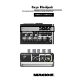
1
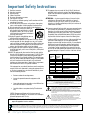
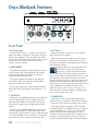
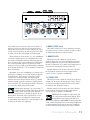
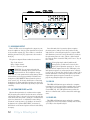
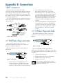
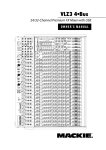
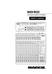
Onyx Blackjack Premium 2x2 USB Recording Interface OWNER’S MANUAL 1 SIG/OL INPUT MONITOR 2 LINE HI-Z SIG/OL 2x2 USB RECORDING INTERFACE LINE HI-Z MONO STEREO 30 20 -15dB USB POWER 30 U U PHANTOM 40 20 60 +45dB U GAIN U 40 -15dB 60 +45dB OO GAIN MAX TO MON OO MAX MONITOR PHONES 2 MONITOR OUT USB R L YX ON BAL /UNBAL BAL/UNBAL MAX OO MIC PR E 1 YX ON MIC PR E Important Safety Instructions 1. 2. 3. 4. 5. 6. 7. Read these instructions. Keep these instructions. Heed all warnings. Follow all instructions. Do not use this apparatus near water. Clean only with a dry cloth. Do not block any ventilation openings. Install in accordance with the manufacturer’s instructions. 8. Do not install near any heat sources such as radiators, heat registers, stoves, or other apparatus (including amplifiers) that produce heat. 9. Only use attachments/accessories specified by the manufacturer. 10. Use only with a cart, stand, tripod, bracket, or PORTABLE CART WARNING table specified by the manufacturer, or sold with the apparatus. When a cart is used, use caution when moving the cart/apparatus combination to avoid injury from tip-over. 11. Unplug this apparatus during lightning storms or when unused for long periods of time. 12. Refer all servicing to qualified service personnel. Servicing is required when the apparatus has been damaged in any way, such as powersupply cord or plug is damaged, liquid has been spilled or objects have fallen into the apparatus, the apparatus has been exposed to rain or moisture, does not operate normally, or has been dropped. 13. This apparatus shall not be exposed to dripping or splashing, and no object filled with liquids, such as vases or beer glasses, shall be placed on the apparatus. 14.NOTE: This equipment has been tested and found to comply with the limits for a Class B digital device, pursuant to part 15 of the FCC Rules. These limits are designed to provide reasonable protection against harmful interference in a residential installation. This equipment generates, uses, and can radiate radio frequency energy and, if not installed and used in accordance with the instructions, may cause harmful interference to radio communications. However, there is no guarantee that interference will not occur in a particular installation. If this equipment does cause harmful interference to radio or television reception, which can be determined by turning the equipment off and on, the user is encouraged to try to correct the interference by one or more of the following measures: • Reorient or relocate the receiving antenna. • Increase the separation between the equipment and the receiver. • Connect the equipment into an outlet on a circuit different from that to which the receiver is connected. • Consult the dealer or an experienced radio/TV technician for help. CAUTION: Changes or modifications to this device not expressly approved by LOUD Technologies Inc. could void the user's authority to operate the equipment under FCC rules. WARNING — To reduce the risk of fire or electric shock, do not expose this apparatus to rain or moisture. 15. This apparatus does not exceed the Class A/Class B (whichever is applicable) limits for radio noise emissions from digital apparatus as set out in the radio interference regulations of the Canadian Department of Communications. ATTENTION — Le présent appareil numérique n’émet pas de bruits radioélectriques dépassant las limites applicables aux appareils numériques de class A/de class B (selon le cas) prescrites dans le réglement sur le brouillage radioélectrique édicté par les ministere des communications du Canada. 16. Exposure to extremely high noise levels may cause permanent hearing loss. Individuals vary considerably in susceptibility to noise-induced hearing loss, but nearly everyone will lose some hearing if exposed to sufficiently intense noise for a period of time. The U.S. Government’s Occupational Safety and Health Administration (OSHA) has specified the permissible noise level exposures shown in the following chart. According to OSHA, any exposure in excess of these permissible limits could result in some hearing loss. To ensure against potentially dangerous exposure to high sound pressure levels, it is recommended that all persons exposed to equipment capable of producing high sound pressure levels use hearing protectors while the equipment is in operation. Ear plugs or protectors in the ear canals or over the ears must be worn when operating the equipment in order to prevent permanent hearing loss if exposure is in excess of the limits set forth here: Duration, per day in hours 8 6 4 3 2 1.5 1 Sound Level dBA, Slow Response 90 92 95 97 100 102 105 0.5 110 0.25 or less 115 Typical Example Duo in small club Subway Train Very loud classical music Matty screaming at desTROYer about deadlines Loudest parts at a rock concert CAUTION AVIS RISK OF ELECTRIC SHOCK. DO NOT OPEN RISQUE DE CHOC ELECTRIQUE. NE PAS OUVRIR CAUTION: TO REDUCE THE RISK OF ELECTRIC SHOCK DO NOT REMOVE COVER (OR BACK) NO USER-SERVICEABLE PARTS INSIDE. REFER SERVICING TO QUALIFIED PERSONNEL ATTENTION: POUR EVITER LES RISQUES DE CHOC ELECTRIQUE, NE PAS ENLEVER LE COUVERCLE. AUCUN ENTRETIEN DE PIECES INTERIEURES PAR L'USAGER. CONFIER L'ENTRETIEN AU PERSONNEL QUALIFIE. AVIS: POUR EVITER LES RISQUES D'INCENDIE OU D'ELECTROCUTION, N'EXPOSEZ PAS CET ARTICLE A LA PLUIE OU A L'HUMIDITE The lightning flash with arrowhead symbol within an equilateral triangle is intended to alert the user to the presence of uninsulated "dangerous voltage" within the product's enclosure, that may be of sufficient magnitude to constitute a risk of electric shock to persons. Le symbole éclair avec point de flèche à l'intérieur d'un triangle équilatéral est utilisé pour alerter l'utilisateur de la présence à l'intérieur du coffret de "voltage dangereux" non isolé d'ampleur suffisante pour constituer un risque d'éléctrocution. The exclamation point within an equilateral triangle is intended to alert the user of the presence of important operating and maintenance (servicing) instructions in the literature accompanying the appliance. Le point d'exclamation à l'intérieur d'un triangle équilatéral est employé pour alerter les utilisateurs de la présence d'instructions importantes pour le fonctionnement et l'entretien (service) dans le livret d'instruction accompagnant l'appareil. Correct disposal of this product. This symbol indicates that this product should not be disposed of with your household waste, according to the WEEE Directive (2002/96/EC) and your national law. This product should be handed over to an authorized collection site for recycling waste electrical and electronic equipment (EEE). Improper handling of this type of waste could have a possible negative impact on the environment and human health due to potentially hazardous substances that are generally associated with EEE. At the same time, your cooperation in the correct disposal of this product will contribute to the effective usage of natural resources. For more information about where you can drop off your waste equipment for recycling, please contact your local city office, waste authority, or your household waste disposal service. 2 Onyx Blackjack Quick Start We realize that you must be really keen to try out your new Onyx Blackjack 2x2 USB Recording Interface. But please read the safety instructions on page 2, then have a look through some of the features and details in this manual first. 3. [For Mac users; PC users will have already completed this step during the driver installation.] Push the USB cable securely into the USB connector on the rear panel of the interface, and plug the other end into any open USB slot of the computer. Note: The Blackjack is class-compliant and will work right out of the box. However, if you are using it in conjunction with a PC running Microsoft Windows, you should download and install the latest ASIO driver from http://www.mackie.com/products/onyxblackjack/ to achieve the best possible performance. 4. If your microphone requires phantom power, turn on the 48V phantom power button. Setup Use the interface in a nice clean and dry environment, free from dryer lint and dust bunnies. Zero the controls 1. Fully turn down all the knobs to minimum, fully counter-clockwise. Yup, all of five of 'em! 2. Make sure all buttons are in the out position. Only four here! Connections and Setup 1. Before plugging into a computer, connect the TRS 1/4" monitor outputs of the interface to the line-level inputs of your studio monitors or amplifier(s). Make sure the studio monitors or amplifier(s) are off for the time being, as well. 2. [For PC users; Mac users may ignore this step.] Prior to connecting the device, make sure to download the latest driver software from: http://www.mackie.com/products/onyxblackjack/ Instructions for installing the driver are included in the .zip file located on the product page. After running the driver installation, you may return to these instructions to check basic functionality. Part No. SW0865 Rev. C 10/10 ©2010 LOUD Technologies Inc. All Rights Reserved. BJs rule! Blonde jokes, Bon Jovi, B.J. and the Bear, Ben and Jerry's, blue jeans, band jams, bungee jumping, Billy Joel, bon jour's, Bijou Phillips (ok, that's a stretch) and, of course, the Mackie Onyx Blackjack 2x2 USB Recording Interface ...any BJs we missed here? 5. Before turning on the studio monitors or amplifier(s), turn up the input gain and "tap check" the microphone to make sure the SIG/OL LED illuminates green. 6. Ensuring that you are not too close to them (or you may hear deafening feedback), turn up the studio monitors or amplifier(s), turn up the input monitor [TO MON] knob to about 3 o'clock, then slowly turn up the MONITOR knob while continuing to tap check to ensure that the analog inputs are audible through the monitors. Headphones may also be used to check levels. 7. Now open your DAW of choice and get to work! Other Notes • When shutting down, turn off any power amplifiers or powered speakers first. When powering up, turn them on last. This will reduce the chance of turn-on or turn-off thumps. • Always turn down the phones level when making connections or doing anything that may cause loudness in the headphones. This will help protect your hearing. • Always turn down the monitor level when making connections to the interface. Better yet, shut down the computer first. • Save the shipping box! Owner's Manual 3 Introduction As the saying goes, good things come in small packages, and the Mackie Onyx Blackjack is just that! Comparable in size and weight to a brick of cheese or a package of hot dogs, this 2x2 USB recording interface may not fill your tummy. However, this powerful piece allows you to connect with nearly any DAW in existence. As such, it provides you with the right tools to record and playback as many #1 hits as you can write. It all starts at the inputs which feature Mackie's renowned premium Onyx preamps...and in "combo jack" style at that, so it accepts both XLR and 1/4" TS/TRS connectors. Both inputs are equipped with DIs (slyly disguised as hi-z) so instruments may be connected directly to the interface. And what good would the mic inputs be without the ability to add phantom power, if needed? So 48V phantom power is readily available at the touch of a switch! Additional flexibility also occurs at the outputs. For example, there are multiple knobs for separate level control of monitors and headphones. Also, monitoring is accomplished in mono or stereo with zero-latency. The interface is compatible with both Mac and PC computers, as well as with most major DAWs so you can get started instantly. You don't have software? No worries, Mackie's Tracktion 3 Hardware Bundle is included. The Onyx Blackjack starts at the inputs and high quality converters, but it ends with your masterpiece. You have a fine piece of pro audio gear in your hands, congratulations! Time to fire up the computer! 4 Onyx Blackjack Features • Two boutique-quality Onyx mic preamps with class-leading fidelity and dynamic range. • High-headroom design with ultra-low noise and distortion. • Professional 24-bit recording/playback via 2x2 USB. • High-end Cirrus Logic® AD/DA converters with 114 dB dynamic range (A-weighted). • True analog hardware monitoring of inputs, in mono or stereo, for easy zero-latency recording. • Compatible with most major DAWs. • Logic® • SONAR™ • Cubase® • Ableton® Live • Final Cut Pro® • ...and more • Built-in DI on each input for direct connection of guitars, basses, etc. • 48V phantom power for use with studio-quality condenser microphones. • USB bus-powered, eliminating need for separate power cable. • Separate studio monitor and headphone outs with independent level control. • Sleek, ergonomic "Built-Like-A-Tank" desktop design. • Includes Tracktion 3™ Music production software. Contents IMPORTANT SAFETY INSTRUCTIONS......................... 2 QUICK START........................................................... 3 INTRODUCTION....................................................... 4 TABLE OF CONTENTS................................................ 5 HOOKUP DIAGRAMS............................................... 6 FEATURES................................................................ 8 REAR PANEL......................................................... 8 1. MIC/LINE INPUTS..................................... 8 2. 1/4" L/R MONITOR OUT.......................... 8 3. USB INPUT/OUTPUT................................. 8 FRONT PANEL..................................................... 10 4. GAIN CONTROL....................................... 10 5. SIG/OL LED............................................ 10 6. HI-Z Switch............................................ 10 7. TO MON Level........................................ 10 8. MONO/STEREO Switch............................ 10 9. MONITOR Level...................................... 11 10. PHONES Level......................................... 11 11. HEADPHONE OUTPUT.............................. 11 12. 48V PHANTOM POWER Switch and LED... 11 13. USB LED.................................................. 11 14. POWER LED............................................ 11 APPENDIX A: SERVICE INFORMATION..................... 12 APPENDIX B: CONNECTIONS.................................. 13 APPENDIX C: TECHNICAL INFORMATION................. 15 APPENDIX D: USB REVISITED................................. 18 LIMITED WARRANTY.............................................. 19 How To Use This Manual The first pages after the table of contents are the hookup diagrams. These show typical setups for fun times with your interface. Next is a detailed tour of the entire interface. The descriptions are divided into sections, just as your interface is organized into distinct zones: • Rear Panel • Front Panel Throughout these sections you’ll find illustrations with each feature numbered and described in nearby paragraphs. This icon marks information that is critically important or unique to the interface. For your own good, read them and remember them. This icon will lead you to some explanations of features and practical tips. Go ahead and skip these if you need to leave the room in a hurry. Owner's Manual 5 Hookup Diagrams MR5 Studio Monitors Condenser microphone MR5 Studio Monitors Acoustic Guitar Condenser Microphones Desktop Computer Headphones 2 MONITOR OUT R USB L 1 1 SIG/OL 2 LINE HI-Z SIG/OL INPUT MONITOR 20 U -15dB BAL /UNBAL 1 2x2 USB RECORDING INTERFACE LINE HI-Z SIG/OL PHANTOM USB 40 20 60 +45dB U GAIN 40 -15dB 2 LINE HI-Z SIG/OL 60 +45dB GAIN MAX TO MON OO MAX MONITOR OO MAX INPUT MONITOR 2x2 USB RECORDING INTERFACE MONO STEREO U -15dB PHONES 1 PHANTOM USB POWER 30 U 20 OO 1 YX MI C P R E ON BAL/UNBAL LINE HI-Z POWER 30 U L YX MI C P R E ON 30 U R YX MI C P R E ON BAL/UNBAL MONO STEREO 30 Headphones 2 MONITOR OUT USB YX MI C P R E ON BAL /UNBAL Desktop Computer 40 20 60 +45dB U GAIN U 40 -15dB 60 +45dB GAIN OO MAX TO MON OO MAX MONITOR OO MAX PHONES 2 Here is a simplistic view on how to record multiple tracks, even with only two inputs! This is a two (or more) part process and we will start with the first hookup diagram (shown above left). Our first goal is to track an acoustic guitar. A pair of mics set up in a stereo configuration are inserted to XLR inputs one and two. Engage the 48V phantom power switch. Headphones are attached to the phones output for recording while a pair of Mackie MR5 studio monitors are attached to the monitor outputs for playback. A desktop computer is attached via USB where the installed DAW software captures your brilliance. The input [gain] knobs should be up, the phones knob should be up, the monitor knob should be down (to eliminate feedback) and the direct monitor send should be up with the mono/stereo switch engaged [stereo] so you may hear yourself (or the artist if that is not you). Step 2 (above right) is exactly the same set-up, except we'll be overdubbing vocals over the alreadytracked acoustic guitar. Remove the mics used to track guitar and replace them with one large diaphragm condenser mic, attached to input one; be sure to disengage the hi-z and mono/stereo switches [mono]. All other knobs shall remain in the same position. Make sure the DAW is set up to accept input 1 to DAW track 3 and press record. When the perfect take has been recorded, turn the phones knob down and the monitor knob up to listen to it through the studio monitors, and begin your solid gold mix... It also happens that diagram #2 works as your typical podcaster setup, too! Typical Singer/Songwriter Setup 6 Onyx Blackjack Laptop Condenser microphone Condenser microphone Headphones 2 MONITOR OUT R USB L 1 YX MI C P R E ON BAL /UNBAL 1 SIG/OL 2 LINE HI-Z SIG/OL BAL/UNBAL INPUT MONITOR 2x2 USB RECORDING INTERFACE LINE HI-Z MONO STEREO 30 20 -15dB PHANTOM USB POWER 30 U U YX MI C P R E ON 40 20 60 +45dB U GAIN U 40 -15dB 60 +45dB GAIN OO MAX TO MON OO MAX MONITOR OO MAX PHONES Let's say that your favorite band is in town for their fourth farewell tour (but this time they really mean it!). Let's also say that they allow their fans to record live shows for posterity. You're in luck! Toss your laptop, a couple of mics and mic stands, headphones and the Onyx Blackjack into your backpack and head down to the venue. Here is how to record the live show in three easy steps: 1. Connect everything as shown in the hookup diagram above. 2. Turn the input [gain] knobs up, phones knob up and monitor knob down on the Onyx Blackjack. 3. Start recording the show with the DAW of your choice. And if you want to listen on phones, just engage the mono/stereo switch and turn the direct monitor send up in conjunction with the headphones. It's that easy! If you want to make extra sure that the DAW is capturing the show, simply turn down the direct monitor send and make sure the DAW is set up to output the signal it's recording. This setup also works for recording a Podcast, or other field recordings you may want for personal projects, work assignments and more. Typical Field Recording Setup Owner's Manual 7 Onyx Blackjack Features 2 MONITOR OUT USB R L 1 YX MIC PRE ON 3 BAL /UNBAL 2 BAL/UNBAL YX MIC PRE ON 1 Rear Panel 1. MIC/LINE/HI-Z INPUTS PHANTOM POWER These dual Onyx mic preamps accept both balanced microphone inputs from an XLR connector and balanced and unbalanced line-level inputs from a 1/4" TRS connector. The microphone preamps feature our Onyx design, with higher fidelity and headroom rivaling any standalone mic preamp on the market today. Most modern professional condenser mics require 48V phantom power, which lets the interface send low-current DC voltage to the mic’s electronics through the same wires that carry audio. (Semi-pro condenser mics often have batteries to accomplish the same thing.) “Phantom” owes its name to an ability to be “unseen” by dynamic mics (Shure SM57/SM58, for instance), which don’t need external power and aren’t affected by it anyway. The XLR inputs are wired as follows: Pin 1 = Shield or ground Pin 2 = Positive (+ or hot) Pin 3 = Negative (– or cold) The 1/4" jacks share circuitry (but not phantom power) with the mic preamps, and can be driven by balanced or unbalanced sources. To connect balanced lines to these inputs, use a 1⁄4" Tip-Ring-Sleeve (TRS) plug, wired as follows: Tip = Positive (+ or hot) Ring = Negative (– or cold) Sleeve = Shield or ground To connect unbalanced lines to these inputs, use a 1⁄4" mono (TS) phone plug, wired as follows: Tip = Positive (+ or hot) Sleeve = Shield or ground This line-level input can also accept instrument-level signals if the hi-z switch [6] is pressed in. This allows you to connect guitars directly into either channel without the need for a DI box. 8 Onyx Blackjack Phantom power may be selected by depressing the interface's phantom power switch [12]. Never plug single-ended (unbalanced) microphones, or ribbon mics into the mic input jacks if phantom power is on. Do not plug instrument outputs into the mic XLR input jacks with phantom power on, unless you are certain it is safe to do so. 2. 1/4" L/R MONITOR OUT These 1/4" connectors provide a balanced or unbalanced line-level signal that is designed to be used to provide a monitor mix to a pair of powered studio monitors, or amplifier powering passive studio monitors. 2 MONITOR OUT USB R L 1 YX MIC PRE ON 3 BAL /UNBAL 2 BAL/UNBAL YX MIC PRE ON 1 3. USB INPUT/OUTPUT The built-in USB interface allows for some powerful and flexible routing. It is a 2x2 interface allowing you to record two streams, and/or input stereo playback from a computer and route it to the monitor outputs [2] or headphones [11]. To use this feature with a PC, first download the PC ASIO driver from http://www.mackie.com/products/onyxblackjack/. If connecting to a Mac, the interface will show up as a 2x2 device with no driver required. The 2x2 USB routing of the Onyx Blackjack is a potent thing to behold. Input signals are always sent directly to the computer, yet also routable directly to monitor and headphones using the small but powerful input monitor knob[7]. Similarly, stereo playback and/or DAW outputs 1-2 are always routed back into the device for monitoring and overdubbing (unless you choose to mute them in software). Since the phones and monitor outputs have separate volume controls, users are free to monitor using either, neither or both. And because analog input signals may be blended in with playback signals for monitoring purposes – using the to mon knob [7] in the input monitor section – overdubs can occur in real-time without the burden of computer-induced latency. Conversely, if you want to add and monitor computersupplied effects or processing to a signal, simply turn the to mon knob [7] down, make sure the buffer size is set relatively low and that the DAW is set to output to the Onyx Blackjack while recording. Most DAWs are set up this way by default, and you will simply have to choose the Onyx Blackjack as your primary interface in the DAW's audio settings. Success here is partially dependent upon the computer's speed. It needs to be fast enough to run at low buffer sizes so that there is no noticeable latency between the input signal and, say, the reverb return. Be sure to review the software requirements on http://www.mackie.com/products/onyxblackjack/ to confirm that the latest device drivers are currently in use. Owner's Manual 9 Onyx Blackjack Features 1 2 5 6 LINE HI-Z SIG/OL SIG/OL INPUT MONITOR 8 LINE HI-Z 12 MONO STEREO 30 20 -15dB PHANTOM 14 USB POWER 30 U U 13 2x2 USB RECORDING INTERFACE 40 20 60 +45dB U 4 GAIN U 40 -15dB 60 +45dB OO GAIN 7 MAX TO MON OO 9 MAX MONITOR OO 10 MAX PHONES 11 Front Panel “U” like Unity gain 6. HI-Z Switch Mackie interfaces have a “U” symbol on the preamp inputs. It stands for “unity gain,” meaning no change in signal level if supplying a line-level signal. The labels on the controls are measured in decibels (dB), so you’ll know what you’re doing level-wise if you choose to change a control’s settings. Engage this switch if you want to connect guitars directly to the 1/4" line inputs. 4. GAIN CONTROL Plugging a guitar into a lower-impedance linelevel input can result in the loss of high frequencies, causing an unnatural and dull sound. Normally, you must use a direct box between a guitar and the interface’s input, which serves to convert the impedance of the guitar from high to low. These hi-z inputs make the need for a direct box unnecessary. However: The hi-z inputs are unbalanced (when the switch is in), so if you’re doing a live show and running a long cord between the instrument and the Onyx Blackjack (say over 25 or 30 feet), it is best to use a direct box with a balanced output to avoid picking up noise over the length of the cord. The gain knobs adjust the input sensitivity of the mic and line inputs. This allows signals from the outside world to be adjusted to run through each input at optimal internal operating levels. If the signal originates through the mic XLR jack, there will be 0 dB of gain with the knob fully down, ramping to 60 dB of gain fully up. The 1⁄4" line inputs have 15 dB of attenuation fully down and 45 dB of gain fully up, with unity gain "U" at 10:00. 5. SIG/OL LED This dual-colored LED will illuminate green when the channel's input signal (at least -20 dBu) is present, indicating signal (SIG). It will remain lit non-stop so long as there is signal above -20 dBu present in that channel. This dual-colored LED will illuminate red when the channel's input signal is too high, indicating a signal overload (OL). This should be avoided, as distortion will occur. If the OL LED comes on regularly, check that the gain control [4] is set correctly for your input device. 10 Onyx Blackjack Without this switch, you need to use a DI box first, before connecting guitars. If these switches are not pressed in, guitars will not sound good, particularly the high frequency response. 7. TO MON LEVEL This knob is used to monitor input signals using studio monitors or headphones. This input monitoring occurs in the analog domain, resulting in zero-latency. Although the signal from inputs 1 and 2 is always routed directly into the DAW right after gain is applied on the Onyx Blackjack, a "copy" of the analog input signals intended for monitoring purposes is also available via the input monitor section. Simply choose whether to monitor the input(s) in mono or stereo (input 1 hard-panned left, input 2 hard-panned right), 1 2 5 6 LINE HI-Z SIG/OL SIG/OL INPUT MONITOR 8 LINE HI-Z 12 MONO STEREO 30 20 -15dB PHANTOM 14 USB POWER 30 U U 13 2x2 USB RECORDING INTERFACE 40 20 60 +45dB U 4 GAIN U 40 -15dB 60 +45dB GAIN OO 7 MAX TO MON OO 9 MAX MONITOR OO 10 MAX PHONES 11 then slowly increase the level of the to mon knob [7] until you can hear it. Since the to mon knob routes signals directly to both the monitor and phones, either or both of these volume pots must be up at least a little in order to hear this analog input monitoring path. 8. MONO/STEREO Switch When working on "basic tracks" (i.e. not overdubbing over prerecorded material), it is probably best to turn the monitor and/or phones knobs down fairly low and the to mon knob [7] to the maximum. This will ensure the cleanest possible signal to the phones or studio monitors. In fact, you will generally find that having this knob up high (between 3 o'clock and max) is normal for direct monitoring. 9. MONITOR LEVEL Meanwhile, if you are overdubbing (i.e. singing over a guitar part or rapping over an audio bed of pig squeals and explosions), you'll want to control the overall volume of the combined input and output signals with the monitor and/or phones knob [9, 10], and the amount of input you hear in relation to playback with the to mon knob [7]. It's really quite simple. Think of it as a "more me" knob and you'll be golden. Turning up the input gain [4], to mon knob [7] and monitor knob [9] with a microphone plugged in may result in some really nasty distortion. Typically, you will want to record with the phones up and monitor down. Then make sure to turn down the to mon knob when you want to hear playback of what was just recorded (without the interference of the microphone still routed to the monitors or headphones). This switch allows you to choose whether to monitor the inputs in mono or stereo. Signals are still recorded as independent streams in either scenario. This knob is used to adjust the volume at the monitor output [2], from off to maximum gain (max). When microphones are connected, always make sure that the To Mon knob [7] is down in the input monitor section before turning the monitor volume up. Monitor and phones share the same "mix", whether that's playback, signals sent via the input monitor section, or both (e.g. while overdubbing). 10. PHONES LEVEL This knob is used to adjust the volume at the phones output [11], from off to maximum gain (max). Phones are ideal for use with the input monitor section when recording in just about all scenarios. Monitor and phones share the same "mix", whether that's playback, signals sent via the input monitor section, or both (e.g. while overdubbing). WARNING: The headphone amp is loud, and can cause permanent hearing damage. Even intermediate levels may be painfully loud with some headphones. BE CAREFUL! Always turn this control all the way down before connecting headphones or doing anything new that may affect the headphone volume. Then turn it up slowly as you listen carefully. Owner's Manual 11 1 5 6 SIG/OL INPUT MONITOR 2 LINE HI-Z SIG/OL 8 LINE HI-Z 12 MONO STEREO 30 20 -15dB PHANTOM 14 USB POWER 30 U U 13 2x2 USB RECORDING INTERFACE 40 20 60 +45dB U 4 GAIN U 40 -15dB 60 +45dB OO GAIN 7 MAX TO MON OO 9 MAX MONITOR OO 10 MAX PHONES 11 11. HEADPHONE OUTPUT This 1/4" TRS connector supplies the output to your stereo headphones. It is the same signal that is routed to the monitor outputs [2]. The volume is controlled with the phones knob [10], right next to the monitor knob [9]. The phones output follows standard conventions: Tip = Left channel Ring = Right channel Sleeve = Common ground WARNING: Yes, we just mentioned this exact same warning above, but that is how important this is...the headphone amp is loud, and can cause permanent hearing damage. Even intermediate levels may be painfully loud with some headphones. BE CAREFUL! Always turn the phones level control [10] all the way down before connecting headphones or doing anything new that may affect the headphone volume. Then turn it up slowly as you listen carefully. 12. 48V PHANTOM POWER and LED Most modern professional condenser mics require 48V phantom power, which lets the interface send lowcurrent DC voltage to the mic’s electronics through the same wires that carry audio. (Semi-pro condenser mics often have batteries to accomplish the same thing.) “Phantom” owes its name to an ability to be “unseen” by dynamic mics (Shure SM57/SM58, for instance), which don’t need external power and aren’t affected by it anyway. 12 Onyx Blackjack Press this switch in if your microphone requires phantom power. (Always check the position of this switch before connecting microphones.) A green LED will illuminate just to the left of this switch to indicate that phantom power is active. This is a global switch that affects all mic channels' XLR jacks at once. Yes, all two of them. Never plug single-ended (unbalanced) microphones, or ribbon mics into the mic input jacks if phantom power is on. Do not plug instrument outputs into the mic XLR input jacks with phantom power on, unless you know for certain it is safe to do so. Be sure the channel's gain control [4] is turned down when connecting microphones to the mic inputs when phantom power is turned on, to prevent pops from getting through to the speakers. 13. USB LED This LED will illuminate green when the computer is powered on and connected successfully and securely (via USB) to the Onyx Blackjack. Different from the Power LED [14], the USB light informs you that the device is "enumerated", and in a functional and happy state. 14. POWER LED This LED will illuminate green when the computer is powered on and connected successfully and securely (via USB) to the Onyx Blackjack. Appendix A: Service Information If you think your interface has a problem, please check out the following troubleshooting tips and do your best to confirm the problem. Visit the Support section of our website (www.mackie.com) where you will find lots of useful information such as FAQs, documentation and any updated PC drivers etc. You may find the answer to the problem without having to send your interface away. Troubleshooting Repair Bad Input For warranty service, refer to the warranty information on page 19. • Is the input gain set correctly? • Is the input OL LED on? • Try the same source signal in the other input, set up exactly like the suspect input. • Is phantom power required for your microphone? Bad Output • Unplug anything from the monitor out, just in case one of your external pieces has a problem. • Make sure that you are not overdriving your amplifiers. Check the loudspeaker average load impedance is not less than the minimum your amplifier can handle. Check the speaker wiring. Non-warranty service for Mackie products is available at a factory-authorized service center. To locate your nearest service center, visit www.mackie.com, click “Support” and select “Locate a Service Center.” Service for Mackie products living outside the United States can be obtained through local dealers or distributors. If you do not have access to our website, you can call our Tech Support department at 1-800-898-3211, Monday-Friday during normal business hours, Pacific Time, to explain the problem. Tech Support will tell you where the nearest factory-authorized service center is located in your area. Noise • Turn the input gains down, one by one. If the offending noise disappears, it’s either that input or whatever is plugged into it. If you unplug the whatever-is-plugged-into-it and turn the input back up and the noise is gone, it’s from your whatever. Power • The power LED should come on if the interface is connected to a computer, and the computer is powered on. Check to make sure that the computer's power cord is securely plugged in. Owner's Manual 13 Appendix B: Connections “XLR” Connectors Mackie interfaces use 3-pin female “XLR” connectors on all microphone inputs, with pin 1 wired to the grounded (earthed) shield, pin 2 wired to the “high” (”hot” or positive polarity) side of the audio signal and pin 3 wired to the “low” (“cold” or negative polarity) side of the signal. See Figure A. Use a male “XLR”-type connector, usually found on the nether end of what is called a “mic cable,” to connect to a female XLR jack. 2 SHIELD HOT COLD SHIELD COLD 3 HOT 1 3 1 3 1 2 SHIELD COLD 2 • Stereo Headphones, and rarely, stereo microphones and stereo line connections. When wired for stereo, a 1⁄4" TRS jack or plug is connected tip to left, ring to right and sleeve to ground (earth). Mackie interfaces do not directly accept 1-plug-type stereo microphones. They must be separated into a left cord and a right cord, which are plugged into two mic preamps. • Unbalanced Send/Return circuits. When wired as send/return “Y” connector, a 1⁄4" TRS jack or plug is connected tip to signal send (output from interface), ring to signal return (input back into interface), and sleeve to ground (earth). 1⁄4" TS Phone Plugs and Jacks “TS” stands for Tip-Sleeve, the two connections available on a “mono” 1⁄4" phone jack or plug. See Figure C. HOT Figure A: XLR Connectors SLEEVE 1⁄4" TRS Phone Plugs and Jacks SLEEVE SLEEVE TRS jacks and plugs are used in several different applications: RING SLEEVE SLEEVE RING TIP TIP SLEEVE Figure C: TS Plug TS jacks and plugs areRING used in many different SLEEVE SLEEVE RING TIP a pplications, always unbalanced. The tip is connected to TIP the audio signal and the sleeve to ground (earth). Some RING examples: • Unbalanced microphones TIP RING TIP SLEEVE Figure B: 1⁄4" TRS Plugs • Balanced mono circuits. When wired as a balanced connector, a 1⁄4" TRS jack or plug is connected tip to signal high (hot), ring to signal low (cold), and sleeve to ground (earth). 14 Onyx Blackjack TIP TIP TIP “TRS” stands for Tip-Ring-Sleeve, the three TIP c onnections available on a “stereo” 1⁄4" or “TIPbalanced” phone jack or plug. See Figure B. SLEEVE SLEEVE TIP SLEEVE • Electric guitars and electronic instruments • Unbalanced line-level connections • Speaker connections Don’t use guitar cords for speaker cables! They’re not designed to handle speaker-level signals and could overheat. Appendix C: Technical Information Specifications Noise Characteristics: Attenuation and Crosstalk: Equivalent Input Noise (EIN), mic input to USB record (A/D), 150 Ω source impedance, 22 Hz to 22 kHz: 60 dB (max) gain: –124.0 dBu 1 kHz, 20 Hz to 20 kHz bandwidth: To Mon or Monitor knob off/min: <–100 dB 1 kHz, 22 Hz to 22 kHz bandwidth: Any channel to any other: <–80 dB Equivalent Input Noise (EIN), mic input to USB record (A/D), 40 Ω source impedance, A-weighted: 60 dB (max) gain: –126.0 dBu Direct Monitor Output Noise (Monitor and To Mon levels unity/max): –95.0 dBu, 22 Hz to 22 kHz USB Record (A/D) Noise Floor/Dynamic Range (From mic input/min gain, 1 kHz –60 dBFS): –112.0 dBFS Noise, A-weighted, –101 dBu equivalent mic input noise at unity gain (11 dBu = 0 dBFS) –110.0 dB Dynamic range, A-weighted, (relative to –2 dBFS/+9 dBu) USB Playback (D/A) Noise Floor/Dynamic Range (Monitor Output, Monitor level unity/max, To Mon off/min; 1 kHz –60 dBFS): –97.0 dBu Noise, A-weighted, –107 dBFS equivalent digital noise, 106 dB Dynamic Range (relative to +9 dBu) Frequency Response: Mic to Monitor Outputs (direct monitor analog-only path, stereo), unity gain: 15 Hz to 50 kHz +0 dB / –0.2 dB Line to Monitor Outputs (direct monitor analog-only path, stereo), unity gain for 1/4" TRS input: 10 Hz to 25 kHz +0 dB / –1.0 dB USB Through (Indirect monitor A/D+D/A), mic input to monitor output, unity gain (To Mon off/min): 44.1 kHz sample rate: 15 Hz to 21 kHz +0 dB / –0.2 dB 96 kHz sample rate: 15 Hz to 22 kHz +0 dB / –0.2 dB Distortion (THD+N): Mic to monitor (direct monitor analog path, stereo), 1 kHz, 22 Hz to 22 kHz bandwidth: +4 dBu in, min/unity gain, +4 dBu out: <0.002% Line to monitor (direct monitor analog path, stereo), 1 kHz, 22 Hz to 22 kHz bandwidth: +4 dBu in, unity gain, +4 dBu out: <0.002% Common Mode Rejection Ratio (CMRR): Mic input, 150 Ω termination 1 kHz: > 50 dB Maximum Input Levels: Mic input, gain at min (0 dB): +10 dBu Mic input, gain at max (60 dB): –50 dBu Line input, gain at min (–15 dB): +25 dBu Instrument input, gain at min (–15 dB): +8 dBu Maximum Output Levels: Monitor Output at unity/max: Phones at unity/max: +10 dBu 8mW into 600 Ω (1% THD+N) USB: USB 1.1 Sample rates available: 44.1 kHz, 48 kHz Mackie Driver Buffer sizes: 96, 128, 256, 512, 1024 Resolution: 24-bit Audio Class 1.0 compliant at 44.1 kHz / 48 kHz, 24-bit A/D: 114 dB typical dynamic range, 24-bit, A-weighted, 10 Hz to 20 kHz BW D/A: 114 dB typical dynamic range, 24-bit, A-weighted, 10 Hz to 20 kHz BW Meters: Bi-color channel meters: Red overload, +7 dBu (–4 dBFS) Green signal present, –20 dBu (–31 dBFS) Hi-Z to monitor (direct monitor analog path, stereo), 1 kHz, 22 Hz to 22 kHz bandwidth: +0 dBu in, unity gain, +0 dBu out: <0.004% Input Impedance: Mic input: 3 kΩ balanced Phones, 1 kHz, 22 Hz to 22 kHz bandwidth: 7mW into 600 Ω: <0.003% Line input: 18 kΩ balanced 9 kΩ unbalanced Mic to USB Record (A/D), 1 kHz, 22 Hz to fs/2 bandwidth: +4 dBu in, unity gain, –7 dBFS record: <0.002% Hi-Z input: 1 MΩ unbalanced USB Playback to Monitor Out (D/A), 1 kHz, 22 Hz to 22 kHz bandwidth (To Mon off/min, Monitor unity/max): –6 dBFS playback, +4 dBu out: <0.002% Owner's Manual 15 Output Impedance: Phones output: 25 Ω Monitor outputs: 300 Ω balanced 150 Ω unbalanced Phantom Power: P48 specification compliant. 48VDC, 10mA max per mic AC Power Requirements: USB Bus powered, high-power device (5V, up to 500mA) Physical Dimensions and Weight Height: 2.80 in / 71.2 mm Depth: 4.32 in / 109.6 mm Width: 6.57 in / 167 mm Weight: 1.5 lb / 0.7 kg LOUD Technologies Inc. is always striving to improve our products by incorporating new and improved materials, components, and manufacturing methods. Therefore, we reserve the right to change these specifications at any time without notice. “Mackie,” and the “Running Man” are registered trademarks of LOUD Technologies Inc. All other brand names mentioned are trademarks or registered trademarks of their respective holders, and are hereby acknowledged. Please check our website for any updates to this manual: www.mackie.com. ©2010 LOUD Technologies Inc. All Rights Reserved. Dimensions 1.10 in / 28 mm WEIGHT 1.5 lb 0.7 kg 4.02 in / 102 mm 4.32 in / 109.6 mm 6.57 in / 167 mm 1 SIG/OL 2 LINE HI-Z SIG/OL INPUT MONITOR 2x2 USB RECORDING INTERFACE LINE HI-Z MONO STEREO 30 20 -15dB PHANTOM USB POWER 2.53 in / 64.2 mm 40 20 60 +45dB U GAIN U R L YX MI C P R E ON BAL /UNBAL 40 -15dB 60 +45dB GAIN OO MAX TO MON OO MAX MONITOR OO MAX PHONES 6.42 in / 163 mm 16 Onyx Blackjack 2 MONITOR OUT USB 30 U U 2.80 in / 71 mm BAL/UNBAL 1 YX MI C P R E ON 1.85 in / 47 mm LINE / HI-Z INPUT 2 MIC LINE / HI-Z INPUT 1 MIC to inputs 1-2 Hi-Z Line Phantom 48V Hi-Z Line Phantom 48V +48V Gain Gain SIG/OL LED SIG/OL LED ADC ADC Ch2 USB to Computer To Mon Ch1 USB to Computer Ch2 USB from Computer Ch1 USB from Computer DAC DAC Stereo Mono Phones Monitor R L PHONES MONITOR Block Diagram Owner's Manual 17 Appendix D: USB revisited USB and the Onyx Blackjack The built-in USB interface allows for some powerful and flexible routing. It is a 2x2 interface allowing you to record two streams, and/or input stereo playback from a computer and route it to the monitor outputs [2] or headphones [11]. To use this feature with a PC, first download the PC ASIO driver from http://www.mackie.com/products/onyxblackjack/. If connecting to a Mac, the interface will show up as a 2x2 device with no driver required. The 2x2 USB routing of the Onyx Blackjack is a potent thing to behold. Input signals are always sent directly to the computer, yet also routable directly to monitor and headphones using the small but powerful input monitor knob[7]. Similarly, stereo playback and/or DAW outputs 1-2 are always routed back into the device for monitoring and overdubbing (unless you choose to mute them in software). Since the phones and monitor outputs have separate volume controls, users are free to monitor using either, neither or both. And because analog input signals may be blended in with playback signals for monitoring purposes – using the to mon knob [7] in the input monitor section – overdubs can occur in real-time without the burden of computer-induced latency. Conversely, if you want to add and monitor computersupplied effects or processing to a signal, simply turn the to mon knob [7] down, make sure the buffer size is set relatively low and that the DAW is set to output to the Onyx Blackjack while recording. Most DAWs are set up this way by default, and you will simply have to choose the Onyx Blackjack as your primary interface in the DAW's audio settings. Success here is partially dependent upon the computer's speed. It needs to be fast enough to run at low buffer sizes so that there is no noticeable latency between the input signal and, say, the reverb return. Be sure to review the software requirements on http://www.mackie.com/products/onyxblackjack/ to confirm that the latest device drivers are currently in use. 18 Onyx Blackjack Blackjack Limited Warranty Please keep your sales receipt in a safe place. This Limited Product Warranty (“Product Warranty”) is provided by LOUD Technologies Inc. (“LOUD”) and is applicable to products purchased in the United States or Canada through a LOUD-authorized reseller or dealer. The Product Warranty will not extend to anyone other than the original purchaser of the product (hereinafter, “Customer,” “you” or “your”). For products purchased outside the U.S. or Canada, please visit www.mackie.com/warranty to find contact information for your local distributor, and information on any warranty coverage provided by the distributor in your local market. LOUD warrants to Customer that the product will be free from defects in materials and workmanship under normal use during the Warranty Period. If the product fails to conform to the warranty then LOUD or its authorized service representative will at its option, either repair or replace any such nonconforming product, provided that Customer gives notice of the noncompliance within the Warranty Period to the Company at: www.mackie.com/support or by calling LOUD technical support at 1.800.898.3211 (toll-free in the U.S. and Canada) during normal business hours Pacific Time, excluding weekends or LOUD holidays. Please retain the original dated sales receipt as evidence of the date of purchase. You will need it to obtain any warranty service. For full terms and conditions, as well as the specific duration of the Warranty for this product, please visit www.mackie.com/warranty. The Product Warranty, together with your invoice or receipt, and the terms and conditions located at www.mackie.com/warranty constitutes the entire agreement, and supersedes any and all prior agreements between LOUD and Customer related to the subject matter hereof. No amendment, modification or waiver of any of the provisions of this Product Warranty will be valid unless set forth in a written instrument signed by the party to be bound thereby. Need help with your new interface? • Visit www.mackie.com and click Support to find: FAQs, manuals, addendums, and other useful information. • Email us at: [email protected]. • Telephone 1-800-898-3211 to speak with one of our splendid technical support chaps (Monday through Friday, normal business hours, PST). Owner's Manual 19 16220 Wood-Red Road NE • Woodinville, WA 98072 • USA United States and Canada: 800.898.3211 Europe, Asia, Central and South America: 425.487.4333 Middle East and Africa: 31.20.654.4000 Fax: 425.487.4337 • www.mackie.com E-mail: [email protected]