1
tutorial
CoMET
Version 5.9
Tutorial
Document Version No: 1.0
© Copyright 1997 – 2005 VaST Systems Technology Corp. All rights reserved
The copyright owner of CoMET hereby disclaims all warranties relating to this software,
whether express or implied, including without limitation any implied warranties of
merchantability or fitness for a particular purpose. The copyright owner will not be liable for
any special, incidental, consequential, indirect or similar damages due to loss of data or any
other reasons, even if the possibility of such damages has been advised. The person using the
software shall bear all the risks as to the consequences of using this software.
Contents
Introduction ................................................................................................................... 7
Conventions used in the tutorials................................................................................. 7
References ................................................................................................................... 7
Standalone C - Hello World ......................................................................................... 9
Overview ..................................................................................................................... 9
Prerequisites ................................................................................................................ 9
Creating a new workspace and project ...................................................................... 10
Navigating the Workspace and Project ..................................................................... 12
Creating a Source File ............................................................................................... 13
Adding the File to the Project.................................................................................... 15
Adding a Build Configuration ................................................................................... 16
Building the Project................................................................................................... 17
Executing the Compiled Project ................................................................................ 19
Key Points ................................................................................................................. 19
CIF Module - SimpleVSP ........................................................................................... 21
Overview ................................................................................................................... 21
The Virtual System Prototype and its Components ............................................... 21
Constructing a VSP in CoMET.............................................................................. 22
The SimpleVSP Example....................................................................................... 22
SimpleVSP Project Block Diagram........................................................................... 23
CoMET Version 5.9 – Tutorial
i
Contents
Prerequisites...............................................................................................................24
Creating a New Workspace and VSP Project ............................................................25
Viewing the Workspace, Project and .fmx File .........................................................28
Creating a Virtual Platform Module Project ..............................................................29
Choosing an .fmx View in the Document window. ...................................................31
Adding Module Instances to the Virtual Platform .....................................................32
Adding a Module Instance by Drag and Drop........................................................33
Viewing the .fmx File as XML...............................................................................33
Adding a Module Instance by Copy and Paste, XML Tree View ..........................35
Adding a Module Instance by Copy and Paste, XML Table View ........................36
Creating an Array of Module Instances .....................................................................38
Viewing the Fmx Report............................................................................................42
Adding Nets and Port Connections............................................................................43
Adding a Net, XML Tree View..............................................................................43
Connecting a Net to an Instance Port, XML Tree View.........................................45
Adding an Instance Port connection, Bus Connection View..................................46
Adding Two Device Port Connections to a Single Net ..........................................46
Adding Clock Connections using the Clock Connection View..............................48
Adding Ports ..............................................................................................................52
Adding a Port..........................................................................................................52
Checking Connections ...............................................................................................56
Building the VirtualPlatform .....................................................................................57
Activating the Project to be Built ...........................................................................57
Building a Project ...................................................................................................58
Adding a VirtualPlatform Module Instance to the VSP.............................................59
Adding a Module Instance using the Module Instance Dialog...............................59
Adding Clock and Reset to SimpleVSP.....................................................................61
Connecting the SimpleVSP Module Instances ..........................................................62
Modifying Module Instance Parameters ....................................................................63
Generating the Prototype Parameter (Platform) Configuration file........................63
Editing the Prototype (Platform) Configuration file...............................................64
Creating and Compiling Target Code ........................................................................67
ii CoMET Version 5.9 – Tutorial
Contents
Adding a Target Image .............................................................................................. 69
Simulating SimpleVSP1............................................................................................ 70
Unconnected Ports..................................................................................................... 71
Debugging a Simulation ............................................................................................ 72
Obtaining a Value Change Dump.............................................................................. 74
Enabling Bus Monitoring....................................................................................... 74
Analyzing the VCD................................................................................................ 76
Obtaining a Metrix Trace .......................................................................................... 77
CIF Peripheral Model - SimpleTimer ....................................................................... 79
Overview ................................................................................................................... 79
Prerequisites .............................................................................................................. 79
Specification.............................................................................................................. 81
SimpleTimer Diagram............................................................................................ 81
Registers82
General Timer Register (GTR).......................................................................... 82
Match Timer Registers (MTR1 and MTR2) ..................................................... 82
Timer Enable Register (TER)............................................................................ 83
Timer Interrupt Enable Register (TIER) ........................................................... 84
Timer Interrupt Flag Register (TIFR)................................................................ 84
Ports 85
Parameters 85
Event Responses for SimpleTimer......................................................................... 86
Creating the SimpleTimer Project ............................................................................. 87
Editing the SimpleTimer fmx file.............................................................................. 89
Adding Ports .......................................................................................................... 90
Adding Tasks ......................................................................................................... 91
Adding a PortOrNetView.................................................................................. 91
Adding Behavioral Code ........................................................................................... 93
General Modeling Guidelines ................................................................................ 93
Events and Callback Functions ......................................................................... 93
State and Instance Data ..................................................................................... 93
How the SimpleTimer Behavior is Implemented................................................... 93
Determining General Timer Register Value...................................................... 93
CoMET Version 5.9 – Tutorial
iii
Contents
Determining When a Match Occurs...................................................................94
The CIF Peripheral Model Template......................................................................95
Template Functions............................................................................................95
Additional Callback and Helper Functions........................................................96
Events and Responses in Behavioral Code.............................................................97
Declarations, Definitions and Instance Data ..........................................................98
Defining Macros ................................................................................................98
Defining the Callback Data Structure ................................................................99
Adding the Callback and Helper Function Prototypes.......................................99
Declaring Instance Data Input and Output Port Handles ...................................99
Declaring Instance Data Registers ...................................................................100
Declaring Instance Data Callback Handles and Callback Data Structures ......101
Declaring Instance Data State Variables..........................................................101
Building the Project ..............................................................................................101
Creating the Behavioral Functions .......................................................................102
Creating the SetupNextMatch, ClearMatchInterrupts, Match and UnMatch
functions 102
Modifying the Task Initialization Function .....................................................106
Modify Reset function .....................................................................................108
Modifying the ReadRegister Function - Respond to Register Reads ..............109
Modifying the WriteRegister Function - Respond to Register Writes............111
Adding the SimpleTimer Device to the Virtual Platform ........................................114
VSP and SimpleTimer Block Diagram.................................................................115
Creating the SimpleTimer1 instance in the Virtual Platform ...............................116
Creating the IrqNet ...............................................................................................117
Adding and Modifying Connections ....................................................................117
Setting the SimpleTimer1 Base Address with a pcx Parameter Override ............120
Creating Target Code............................................................................................120
Adding the Target Image .........................................................................................125
Simulating SimpleVSP1 with SimpleTimer ............................................................125
Output ......................................................................................................................125
SimpleTimer Debug Configuration Software Window Output............................125
SimpleTimer Release Configuration Software Window Output ..........................127
iv CoMET Version 5.9 – Tutorial
Contents
Metrix Output....................................................................................................... 128
CoMET Version 5.9 – Tutorial
v
Introduction
This tutorial covers creating:
• a standalone C project
• a CIF Virtual System Prototype
Conventions used in the tutorials
The following conventions are used in the tutorials.
Choosing an option from a menu is indicated by the notation:
Choose Menu name/option/option .
For example, choosing the New Workspace option from the File menu is indicated by:
Choose File/New Workspace.
Fields or objects within a dialog are preceded by the dialog name. Dialogs are identified by
the window name in the top left corner:
Workspace dialog: Workspace name:
Literal text that you type or select is displayed in a typewriter font: This is text you
type or select.
Buttons you click are indicated as follows:
Click OK
References
• CoMET 5 User Guide
• CoMET Modeling Guide
CoMET Version 5.9 – Tutorial
7
Standalone C - Hello World
Overview
This tutorial covers a simple CoMET project, to compile and run a standalone C Hello World
program. The Hello World tutorial uses no Fabric or other modules and does not model a
hardware system. It demonstrates:
Creating a new workspace
Creating a new project
Navigating the workspace
Creating a new source file
Editing the source in the document editor
Adding the source file to the project
Creating a build configuration
Building the project
Executing the compiled code
Prerequisites
This tutorial assumes:
Comet 5 is installed and open.
Either the Microsoft Visual C++ compiler or the gcc compiler is installed.
CoMET Version 5.9 – Tutorial
9
Standalone C - Hello World
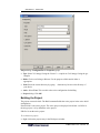
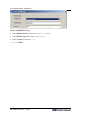
Creating a new workspace and project
Choose File/New Workspace.
Workspace dialog
Workspace Name: Type desired name: Hello
Location: This is set automatically according to Workspace name. Alter if desired.
Workspace dialog: click Next
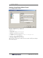
When you create a workspace, CoMET automatically creates a new project. CoMET opens a
dialog for specifying project properties.
10 CoMET Version 5.9 – Tutorial
Standalone C - Hello World
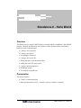
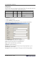
Workspace: Hello dialog: Project panel:
Select General
Project Name: Type Hello1
Location: Accept default or type alternative
C compiler: Select desired compiler, MS Visual C++ or Cygwin Gcc
Select Application
Workspace: Hello dialog: Click Finish
CoMET Version 5.9 – Tutorial
11
Standalone C - Hello World
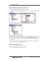
Navigating the Workspace and Project
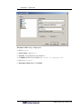
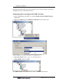
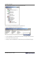
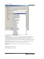
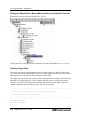
CoMET creates the new workspace and project and displays them in the Workspace window.
The Hello1 project is displayed with a yellow icon, indicating it is of type General.
In the Workspace window, expand the Hello1 project to see the default folders. To expand a
node, click the symbol beside it as shown above. To contract a node, click the symbol
beside it.
For General projects, CoMET creates a Source Files folder, and a Header Files folder, but
creates no files to populate them. For other types of project CoMET generates skeleton code
from templates.
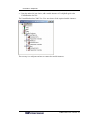
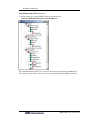
In the Workspace window, expand the Configurations node. This shows the build
configurations in place for this project. CoMET by default creates a debug and release
Microsoft Foundation Classes Windows Application build configuration. We are creating a
console application so we will add this build configuration later.
12 CoMET Version 5.9 – Tutorial
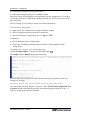
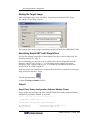
Standalone C - Hello World
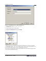
Creating a Source File
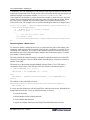
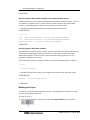
Choose File/New File, or press Ctrl-N, or click the
button in the tool bar.
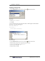
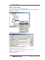
New dialog:
Choose Text Document
Click OK
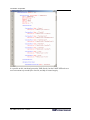
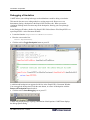
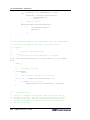
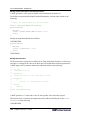
A new text document opens in the Document window. CoMET supplies a default window
title of Text1. Type in the following text:
#include <stdio.h>
void main() {
printf("Hello world\n");
}
Now save the file.
Choose File/Save File, or press Ctrl-S, or click the
button in the tool bar.
Save As dialog: Navigate to the appropriate project directory
Save As dialog: File name: Type hello1.c
Save As dialog: click OK
CoMET Version 5.9 – Tutorial
13
Standalone C - Hello World
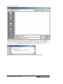
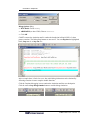
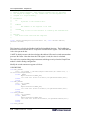
The file now displays with the file name as the window title, and with C syntax coloring.
CoMET determines they syntax coloring choice from the file extension. You can change this
at any time by choosing Edit/Syntax Coloring and selecting a language from the list.
The source file has now been created, but it has still to be added to the project.
14 CoMET Version 5.9 – Tutorial
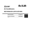
Standalone C - Hello World
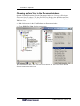
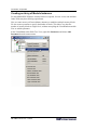
Adding the File to the Project
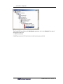
In the Workspace window, open the Hello1 project, Folders node and right click on the
Source Files node to display the context menu.
Source Files context menu: choose Add File
Browse for source files dialog: Navigate to the directory in which you saved hello1.c, select
hello1.c, and click Open
CoMET Version 5.9 – Tutorial
15
Standalone C - Hello World
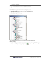
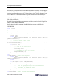
hello1.c appears in the Workspace window, Hello1 project, Source Files folder.
Adding a Build Configuration
This project is to be built as a console application, so we add a new build configuration.
Workspace window, Hello1 project: right click Configurations to display the context menu.
Choose Add Configuration.
16 CoMET Version 5.9 – Tutorial
Standalone C - Hello World
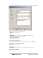
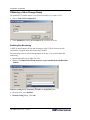
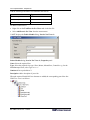
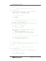
Project dialog: Configuration tab: Properties group:
Type: Select VcConApp if using the Visual C++ compiler or GccConApp if using the gcc
compiler
Mode: Choices are Debug or Release. For the purposes of this tutorial either is
appropriate
Path: Select the current directory by typing. Alternatively browse to the directory of
your choice
Active: Select True. This sets this as the active configuration for building.
Project dialog: Click OK
Building the Project
The project can now be built. The Build command builds the active project in the active build
configuration.
Ensure Hello1 is the active project. The active project is displayed in bold text. As Hello1 is
the only project, it is by default the active project.
If Hello1 is not the active project:
To set the active project:
Right click on the project entry in the Workspace window.
CoMET Version 5.9 – Tutorial
17
Standalone C - Hello World
Select Project Properties from the context menu.
In the Project dialog, Project panel, set Active to True.
Ensure the active build configuration is the appropriate console configuration, VcConApp or
GccConApp. The active configuration is displayed in bold text. This was set to active in the
previous section.
If the VcConApp or GccConApp is not the active build configuration:
To set the active configuration
Right click on the configuration entry in the Workspace window.
Select Configuration Properties from the context menu.
In the Project dialog, Configuration panel, set Active to True.
Alternatively,
Choose Workspace/Active Configurations.
In the Active Configuration dialog, choose the required Type and Mode of build
configuration.
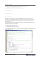
To build the active project, active build configuration:
Choose Workspace/Build, or click the tool bar Build button:
The Output window, Build tab displays build messages.
If the build does not complete successfully, the build messages may indicate a cause. For
example, the message:
Failed to build: The system cannot find the path specified.
may indicate the path to the compiler is incorrect. Choose Tools/Comet Configuration/Tool
Locations tab and confirm that the compiler path points to the parent directory of the bin
directory containing the compiler executable.
18 CoMET Version 5.9 – Tutorial
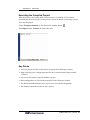
Standalone C - Hello World
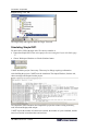
Executing the Compiled Project
When the project is successfully built, you can execute it, or simulate it. The Simulate
command runs the active project. See the previous section for details on activating a project.
To execute the project:
Choose Workspace/Simulate or click the tool bar Simulate button:
The Output window, Software tab shows the result:
Key Points
• Access to projects and files is achieved by navigating in the Workspace window
• Right click on projects, configurations and files to see context menus listing available
functions
• New source files must be explicitly added to a project
• Build configurations are listed under each project in the Workspace window
• The Build command builds the active project, in the active build configuration
• The Simulate command executes the active project
CoMET Version 5.9 – Tutorial
19
CIF Module - SimpleVSP
Overview
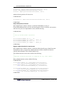
This tutorial demonstrates how to build a Virtual System Prototype (VSP) and simulate it
running target code, using the CoMET System Engineering Environment.
A VSP (Virtual System Prototype) is a constructed from a collection of software projects
made up of source code, compiled modules and xml files. The software runs on a simulation
engine on a host PC, modeling the behavior of a hardware system. You can run target
software developed for the hardware system on the VSP at speeds approaching the speed of
the actual hardware system.
The Virtual System Prototype and its Components
The Virtual System Prototype (VSP) is the top level module. It represents the virtual world in
which simulation takes place. It has no external connections or ports. It contains all other
modules. VSP behavior is determined by the modules it contains. It has no behavior
independently of its modules. A VSP typically contains least one instance of a Virtual
Platform. A VSP is the equivalent of the VHDL test bench.
A Virtual Platform contains instances of other modules, which may include Peripheral
Device models and other Virtual Platforms. It may have ports. Virtual Platform behavior is
determined by the modules it contains. It has no behavior independently of its modules.
A Virtual Processor Model (VPM) models the behavior of a microprocessor. Typically a
VPM is a module within a Virtual Platform. A VPM has ports.
A Peripheral Device model emulates the behavior of physical devices such as interrupt
controllers, clock generators, asynchronous serial interfaces and so on. A Peripheral Device
has ports.
A Net provides a means to connect module instance ports, and is the means by which you
connect devices and platforms in your VSP. You can create clock, logic, vector or bus nets.
CoMET Version 5.9 – Tutorial
21
CIF Module - SimpleVSP
Constructing a VSP in CoMET
CoMET manages a group of projects within a Workspace. To construct a VSP, you first
create a workspace then create a CIF Virtual System Prototype project within it. You also
create CIF Projects for the component Virtual Platforms and Peripheral Devices required by
the system.
You may also use pre-built VPMs and Peripheral Device models.
You specify the hierarchical structure of the VSP and the Virtual Platforms by adding
instances of component modules. You create Nets to connect the Ports of component module
instances. Module instances, Nets and Instance Port connections are specified in a Fabric
Module Definition (.fmx)
You specify the runtime configuration of the component modules by overriding parameters in
the Prototype Configuration (.pcx) file.
To create target software, you write code for the target microprocessor platform and compile
it, using a cross-compiler appropriate for the processor modeled by your VPM, just as you
would for the actual hardware platform.
You can then run the target software on the virtual system prototype. CoMET provides tools
to manage all stages of a VSP project. Using CoMET you can create and edit .fmx files and
.pcx files. You can create, edit and compile module behavior code. For some processors, such
as the ARM processor, you can edit and compile target code within the CoMET environment.
Within the CoMET environment you can specify software build options, build the VSP and
run the simulation.
The SimpleVSP Example
The SimpleVSP example is as simple as possible. It is a functioning prototype with a Virtual
Platform containing a VPM (Virtual Microprocessor Model), memory, and the necessary
support modules. No coding is required. SimpleVSP is built entirely with modules from the
VaST Modules library.
Not all customers receive the Arm926ejs VPM used as an example in this tutorial. The
tutorial uses features common to all microprocessors. You may have to modify some of the
procedures to suit the VPM you choose.
This tutorial does not cover building target code. How you build target code depends on your
choice of VPM. The tools available for the processor modeled by the VPM determine the
appropriate cross-compiler and the target code development environment.
22 CoMET Version 5.9 – Tutorial
CIF Module - SimpleVSP
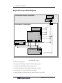
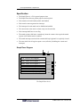
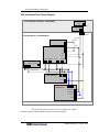
SimpleVSP Project Block Diagram
Virtual System Prototype - SimpleVSP1
VastGpReset1
Reset
VastGpClock1
ResetNet
Clock
ClockNet
PlatformReset
Virtual Platform - VirtualPlatform1
PlatformClock
StdLogic0Net
VastGpStdLogic01
Arm926ejs1
Irq
Fiq
Reset
Clock
DataBus DataBusClock
InstBus
InstBusClock
StdBus1
Bus
BusClock
BusClockIn
StdBus1Net
StdBus1ClockNet
GenericMemory1
Bus
BusClock
Reset
The SimpleVSP project
This tutorial demonstrates:
• Creating a new Workspace and VSP Fabric module project
• Creating a Virtual Platform Fabric module project
• Viewing and editing a Fabric Module Definition (.fmx) file
• Choosing an .fmx View in the Document window.
• Adding instances of modules from the module library to an .fmx file
CoMET Version 5.9 – Tutorial
23
CIF Module - SimpleVSP
• Using the Modules Window
• Adding ports and nets
• Connecting ports and nets
• Using table views of the .fmx file to verify connections and parameters
• Building the VirtualPlatform project
• Adding SimpleVSP1 module instances and connecting them
• Adding a target image to the VSP
• Building the SimpleVSP project
• Running the simulation
• Monitoring output and measuring performance
Prerequisites
This tutorial assumes:
Comet 5 is installed and open.
Either the Microsoft Visual C++ compiler or the gcc compiler is installed
You are familiar with creating and navigating a workspace. These procedures are
covered in the preceding Hello World example
You are familiar with writing and building target code for the microprocessor you will
use in this tutorial. Alternatively it is assumed you have access to someone who can
build the tutorial target code and provide a binary image.
24 CoMET Version 5.9 – Tutorial
CIF Module - SimpleVSP
Creating a New Workspace and VSP Project
Choose File/New Workspace.
Workspace dialog
Workspace Name: Type desired name: SimpleVSP
Location: This is set automatically according to Workspace name. Alter if desired.
Workspace dialog: click Next
When you create a workspace, CoMET automatically creates a new project to go with it.
CoMET opens a dialog for specifying project properties.
CoMET Version 5.9 – Tutorial
25
CIF Module - SimpleVSP
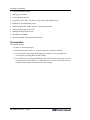
Workspace: SimpleVSP dialog: Project panel:
Select Fabric
Project Name: Type SimpleVSP1
Location: Accept default or type alternative
C compiler: Select desired compiler, MS Visual C++ or Cygwin Gcc
Library (DLL) is only option
Workspace: SimpleVSP dialog: Click Next
When you choose a Fabric project, CoMET creates a new module. CoMET opens a dialog to
specify module properties.
26 CoMET Version 5.9 – Tutorial
CIF Module - SimpleVSP
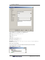
Project: SimpleVSP1 dialog: Fabric Module panel:
Module Class: Select Virtual System Prototype
Module Type: This is the name of the module type by which instances of this module are
classified. Accept the suggested name.
Version: Accept the suggested version.
Project: SimpleVSP1 dialog: Click Finish.
CoMET Version 5.9 – Tutorial
27
CIF Module - SimpleVSP
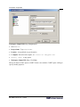
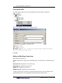
Viewing the Workspace, Project and .fmx File
CoMET creates the new workspace and project and displays them in the Workspace window.
The VSP1 project is displayed with a blue icon, indicating it is of type Fabric.
Expand the SimpleVSP1 project. On creating the Fabric project, CoMET creates a number of
files from templates. The C source and header files contain skeleton code and definitions as a
basis for developing the module. In this tutorial we do not edit these files.
CoMET also creates a Fabric Module Definition XML (.fmx) file defining the structure of the
module. In this tutorial we modify this file to create our SimpleVSP system.
Double click on the .fmx file entry in the Project tree to open the .fmx file in the Document
window. The template .fmx file contains header entries for Parameters, Ports, Nets, Tasks,
Module Instances and Interfaces. It does not yet contain any objects under these headings.
The VSP is the highest level of the module hierarchy. It has no external connections. The
VSP contains all other modules. A VSP typically contains one or more Virtual Platform
modules. The next step is to create and build a Virtual Platform module, as a container for
further modules. We then add an instance of the Virtual Platform to the VSP module.
28 CoMET Version 5.9 – Tutorial
CIF Module - SimpleVSP
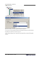
Creating a Virtual Platform Module Project
Choose Workspace/Add New Project
Workspace: SimpleVSP dialog: Project panel:
Select Fabric
Project Name: Type VirtualPlatform
Location: Accept default or type alternative
C compiler: Select desired compiler, MS Visual C++ or Cygwin Gcc
Library (DLL) is only build option
Workspace: SimpleVSP dialog: Click Next
When you choose a Fabric project, CoMET creates a new module. CoMET opens a dialog to
specify module properties.
CoMET Version 5.9 – Tutorial
29
CIF Module - SimpleVSP
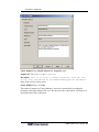
Project: VirtualPlatform dialog: Fabric Module panel:
Module Class: Select Virtual Platform
Accept default values for other fields.
Project: VirtualPlatform dialog: click Finish
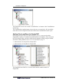
CoMET displays the VirtualPlatform project in the Workspace tree. We have created the
VirtualPlatform module. After we have added module instances to the Virtual Platform, we
can build it and add an instance of the Virtual Platform to the VSP.
The next step is to add module instances to the platform. This can be done using the various
views of the VirtualPlatform.fmx file.
30 CoMET Version 5.9 – Tutorial
CIF Module - SimpleVSP
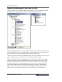
Choosing an .fmx View in the Document window.
Open the VirtualPlatform.fmx file in the Document window (see Viewing the Workspace,
Project and .fmx File, above). The .fmx file XML Tree Display view shows the same basic
structure as the SimpleVSP1 .fmx file. To ensure the VirtualPlatform.fmx file is displayed in
XML tree view:
Right click on a line in the VirtualPlatform.fmx Document window
Choose XML Tree View from the context menu.
We will demonstrate other .fmx views later in this tutorial. All .fmx views can be chosen
from the context menu in this way.
CoMET Version 5.9 – Tutorial
31
CIF Module - SimpleVSP
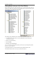
Adding Module Instances to the Virtual Platform
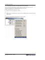
Refer to the SimpleVSP Project Block Diagram, page 23, for the structure of the VSP. The
modules to be added can be found in the VaST modules library. Open the modules window
and expand the Gp and VPM nodes and sub nodes.
The modules to add, identified by their location in the VaST Modules library, are:
• VpmARM926EJS. In this tutorial we use the ARM926EJS. Other VPMs may be
substituted if available.
• Memory: Gp/GenericMemory
• Bus: Bus/StdBus
• StdLogic0: Gp/VastGpStdLogic0
Later we will add, to the SimpleVSP module, the Clock device Gp/VastGpClock and the
Reset device Gp/VastGpReset.
To add module instances, we perform operations on the Module Instances node.
The Modules Window offers several ways to add module instances.
32 CoMET Version 5.9 – Tutorial
CIF Module - SimpleVSP
Adding a Module Instance by Drag and Drop
Click on the ARM926EJS icon in the Modules window.
Drag and drop onto the Module Instances node in the VirtualPlatform.fmx file Document
window.
The .fmx file tree display shows the module instance, with a default instance name.
The default names are acceptable for this tutorial. To change an instance name, select it in the
XML Tree View and press F2, or right click and choose Edit Module Instance from the
context menu. You can also double click and edit the Instance Name in the Module Instance
Properties dialog.
The effect of this procedure is to add, to VirtualPlatform.fmx, XML elements describing the
VPM. To see this, view the .fmx file in XML Text View.
Viewing the .fmx File as XML
Choose the VirtualPlatform.fmx XML Text View.
Scroll to the ARM926EJS1 module instance entry.
CoMET Version 5.9 – Tutorial
33
CIF Module - SimpleVSP
It is possible to edit, search and process the XML directly, but the CoMET SEE tools are a
more convenient way to modify the .fmx file, and help to ensure integrity.
34 CoMET Version 5.9 – Tutorial
CIF Module - SimpleVSP
Adding a Module Instance by Copy and Paste, XML Tree View
Choose XML Tree View in the VirtualPlatform.fmx Document window.
Select the GenericMemory module in the Modules Window (click it). Press Ctrl-C to
copy. Alternatively right click and choose Copy Fabric Module from the context menu.
Select the Module Instances node in the VirtualPlatform.fmx XML Tree View (click it).
Press Ctrl-V to paste. Alternatively right click and choose Paste Fabric Module from the
context menu.
The .fmx XML Tree View shows the module instance, with a default instance name.
CoMET Version 5.9 – Tutorial
35
CIF Module - SimpleVSP
Adding a Module Instance by Copy and Paste, XML Table View
Choose Logic Connection View in the VirtualPlatform.fmx Document window.
Select the StdBus module in the Modules Window (click it). Press Ctrl-C to copy.
Select the VirtualPlatform.fmx Logic Connection View (click anywhere in the table).
Press Ctrl-V to paste.
The .fmx XML Tree View shows the module instance, with a default instance name.
You can paste into any of the table views. The default Connection views show all module
instances, while the default Parameter views filter on module type. None of the module
instances has any connections at this stage, so no connections are shown.
36 CoMET Version 5.9 – Tutorial
CIF Module - SimpleVSP
Using the method of your choice, add a module instance of VastGpStdLogic0 to the
VirtualPlatform.fmx file.
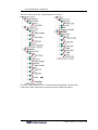
The VirtualPlatform.fmx, XML Tree View now shows all the required module instances.
The next step is to add ports and nets to connect the module instances.
CoMET Version 5.9 – Tutorial
37
CIF Module - SimpleVSP
Creating an Array of Module Instances
For the ARM926EJS VPM three memory blocks are required, for reset vector, code and data.
Other VPMs may have differing requirements.
Here we create an array of GenericMemory instances to model the multiple memory blocks.
We also create a parameter to specify the number of blocks. This allows us to alter the
number of memory blocks at a higher level, without recompiling the VirtualPlatform module.
First we add the parameter.
In the VirtualPlatform.fmx XML Tree View, right click Parameters and choose Add
Parameter from the context menu.
38 CoMET Version 5.9 – Tutorial
CIF Module - SimpleVSP
Fabric Module dialog, Parameter tab, Properties panel
Name: Type NumberOfMemoryBlocks
Type: Select tWord32
Value: type 3
Fmx Access: Accept default Public
Pcx Access: Accept default Public
Description: Determines the size of the array of GenericMemory1
module instances
Other fields: Accept defaults
The description appears in the Fabric Module Definition Report for the module.
Fabric Module dialog: Click OK
CoMET Version 5.9 – Tutorial
39
CIF Module - SimpleVSP
The VirtualPlatform.fmx XML Tree Display shows the new parameter.
Now we alter the GenericMemory1 module instance properties to specify an array of
instances determined by the NumberOfMemoryBlocks parameter.
In the VirtualPlatform.fmx XML Tree View,
Double click the GenericMemory1 element
or
Right click the GenericMemory1 element and select Module Instance Properties from the
context menu.
or
Select the GenericMemory1 node and press Ctrl-P or Enter
40 CoMET Version 5.9 – Tutorial
CIF Module - SimpleVSP
Fabric Module dialog, Module Instance tab, Properties panel:
Number Of: Type NumberOfMemoryBlocks
Description: This is an array of module instances, with the size
of the array determined by the NumberOfMemoryBlocks parameter.
Other fields: Accept existing values
Fabric Module dialog: Click OK
The number of instances of GenericMemory1 can now be determined by overriding the
parameter at the higher SimpleVSP1 level. We show this later in the tutorial. All instances of
GenericMemory1 share connections.
CoMET Version 5.9 – Tutorial
41
CIF Module - SimpleVSP
Viewing the Fmx Report
Save the fmx file (press Ctrl-S) and open the Fmx Report:
To view the prototype report for the .fmx file
Select Tools/Prototype Report
or
click the Prototype Report button
.
CoMET opens the report in the default XML browser.
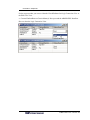
The Summary part of the report shows the Parameters and Module Instances so far created.
You can view the Fmx Report at any time to see an alternative layout of module details. Note
that element descriptions are displayed, and all attributes are visible.
42 CoMET Version 5.9 – Tutorial
CIF Module - SimpleVSP
Adding Nets and Port Connections
The ports of devices at the same level of the module hierarchy must be connected by nets. A
device port can connect directly only to the port of the device's parent module or to the port
of a child module of the device.
Devices within the VirtualPlatform module must be connected by nets.
Referring to the SimpleVSP Project Block Diagram, page 23, there are three nets to create in
the VirtualPlatform module:
• StdBus1Net - type: StdBus - connects VPM and memory
• StdBus1ClockNet - type: StdClock - connects VPM and memory to the BusClock
• StdLogic0Net - type: StdLogic - connects VPM interrupts to logic 0
There are several ways to add nets and connect them to ports.
Adding a Net, XML Tree View
In the VirtualPlatform.fmx XML Tree View, right click on Nets
Choose Add Net from the context menu.
CoMET Version 5.9 – Tutorial
43
CIF Module - SimpleVSP
Fabric Module dialog, Net tab, Properties panel:
Name: Type StdBus1Net
Type: Select StdBus
Description: This connects the VPM and Memory to the StdBus
Accept default for other fields
Fabric Module dialog: click OK
The VirtualPlatform.fmx XML Tree View shows the new net.
44 CoMET Version 5.9 – Tutorial
CIF Module - SimpleVSP
Referring to the SimpleVSP Project Block Diagram, page 23, this net must be connected to
the StdBus device, the VPM and the memory.
Connecting a Net to an Instance Port, XML Tree View
In the VirtualPlatform.fmx XML Tree, open the Module Instances/StdBus1/Instance
Ports node
Right click on Bus and choose Add Port Connection from the context menu
Fabric Module dialog, Port Connection tab, Properties panel:
Port or Net Name: Select StdBus1Net from the list box.
Fabric Module dialog: Click OK
The StdBus1/Instance Ports/Bus node now shows a StdBus1Net connection.
CoMET Version 5.9 – Tutorial
45
CIF Module - SimpleVSP
Adding an Instance Port connection, Bus Connection View
Open the VirtualPlatform.fmx Bus Connection View
Click in the GenericMemory1 row, StdBus1Net column, then click again to display the
list box showing GenericMemory1 ports. Select the Bus port
Click again to display
The Bus Connection View displays the new port connection.
We now want to connect StdBus1Net to two ports on the VPM: the InstBus port and the
DataBus port. This cannot be done in Bus Connection view, so we return to the XML Tree
View.
Adding Two Device Port Connections to a Single Net
VirtualPlatform.fmx XML Tree View:
Open the Module Instances/ARM926EJS1/Instance Ports node
As described in the XML Tree View example above, right click on InstBus
Choose Add Port Connection
Fabric Module dialog, Port Connection tab, Properties panel:
Port or Net Name: Select StdBus1Net from the list box.
Other fields: Accept defaults
Fabric Module dialog: Click OK
46 CoMET Version 5.9 – Tutorial
CIF Module - SimpleVSP
VirtualPlatform.fmx XML Tree View:
Repeat the process to add a StdBus1Net port connection to the
Instances/ARM926EJS1/Instance Ports/DataBus port.
The VirtualPlatform.fmx XML Tree View now shows the ports connected to StdBus1Net.
We will now use the Clock Connection View to create and connect the StdBus1ClockNet.
CoMET Version 5.9 – Tutorial
47
CIF Module - SimpleVSP
Adding Clock Connections using the Clock Connection View
Open the VirtualPlatform.fmx Clock Connection View
Right click anywhere on the grid and select Add Net from the context menu.
The Fabric Module dialog, Net tab is the same as that shown above in Adding a Net, XML
Tree View, page 43.
Fabric Module dialog, Net tab, Properties panel:
Name: Type StdBus1ClockNet
Type: Select StdClock
Description: This connects the StdBus1 BusClock to the memory
and VPM bus clock ports
Accept default for other fields
Fabric Module dialog: click OK
The Clock Connection View shows a column for the new net.
Click in the ARM926EJS1 row, StdBus1ClockNet column, and click again to show the
list box with available ports. Select the DataBusClock port.
Similarly, connect the StdBus1 BusClock port to StdBus1Clock.Net.
Similarly, connect the GenericMemory1 BusClock port to StdBus1ClockNet.
We must now return to XML Tree View to add the second port connection for the VPM.
Choose VirtualPlatform.fmx XML Tree View
Open the Module Instances/ARM926EJS1/Instance Ports node.
48 CoMET Version 5.9 – Tutorial
CIF Module - SimpleVSP
Right click InstBusClock and choose Add Port Connection
Fabric Module dialog, Port Connection tab, Properties panel:
Port or Net Name: Select StdBus1ClockNet from the list box.
Other fields: Accept defaults
Fabric Module dialog: Click OK
The VirtualPlatform.fmx XML Tree View now shows the ports connected to
StdBus1ClockNet.
Save the fmx file (press Ctrl-S) and open the Fmx Report by selecting Tools/Prototype
Report or clicking the Prototype Report button
.
CoMET Version 5.9 – Tutorial
49
CIF Module - SimpleVSP
Scroll down to the Nets entry in the Summary section.
The Nets Summary shows a table with attributes of each Net. It also shows the number of
Connections for each Net.
Click the Name link to move to the detail entry for a Net.
The Net Detail entry shows the attributes and the Instance Port Connections for the Net, with
links to the associated Module Instances for the Port Connection. Click a link to move to the
Module Instance detail entry. This shows Instance Ports and their Connections.
You can use the Fmx Report to check connections.
Referring to the block diagram, we now tie down the VPM Irq and Fiq ports to logic 0.
50 CoMET Version 5.9 – Tutorial
CIF Module - SimpleVSP
In XML Tree View add the Net StdLogic0Net. Right Click Nets and choose Add Net.
Fabric Module, Net tab, Properties:
Name: StdLogic0Net
Type: StdLogic.
Description: This ties the VPM Irq and Fiq ports down to logic 0.
In XML Tree View connect StdLogic0Net to ports Irq and Fiq on the ARM926EJS1
VPM.
In XML Tree View connect StdLogic0Net to port SignalOut on StdLogic01.
The VirtualPlatform.fmx XML Tree View now shows the connections of StdLogic0Net.
CoMET Version 5.9 – Tutorial
51
CIF Module - SimpleVSP
Adding Ports
Referring to the SimpleVSP Project Block Diagram, page 23, the VirtualPlatform needs a
PlatformClock port to connect to the VSP clock and a PlatformReset port to connect to the
VSP reset. These ports can be connected directly to the reset and clock ports on the
VirtualPlatform's child modules.
Adding a Port
VirtualPlatform.fmx, XML Tree View:
Right click Ports
Choose Add Port from the context menu
52 CoMET Version 5.9 – Tutorial
CIF Module - SimpleVSP
Fabric Module dialog, Port tab, Properties panel:
Name: Type PlatformClock
Type: Select StdClock
Description: This connects all module instances within
VirtualPlatform to the VSP clock.
Other fields: Accept defaults
Fabric Module dialog: Click OK
Similarly, add the PlatformReset port.
In VirtualPlatform.fmx, XML Tree View, right click Ports and choose Add Port
Fabric Module dialog, Port tab, Properties panel:
Name: Type PlatformReset
Type: Select StdLogic
Description: This connects all module instances within
VirtualPlatform to the VSP reset.
Other fields: Accept defaults
Fabric Module dialog: Click OK
CoMET Version 5.9 – Tutorial
53
CIF Module - SimpleVSP
The VirtualPlatform.fmx XML Tree View shows the new ports.
Now we connect the VirtualPlatform ports to the child devices.
Open VirtualPlatform.fmx Clock Connection View
Click in the StdBus1 row, PlatformClock.Port column. Click again to show the list box.
Choose BusClockIn from the list box.
Similarly, connect the ARM926EJS1 ClockIn instance port to the PlatformClock port.
54 CoMET Version 5.9 – Tutorial
CIF Module - SimpleVSP
For the next procedure you can use either the VirtualPlatform.fmx Logic Connection View or
the XML Tree View.
Connect PlatformReset to GenericMemory1 Reset port and the ARM926EJS1 ResetPort.
Here we show the Logic Connection View.
CoMET Version 5.9 – Tutorial
55
CIF Module - SimpleVSP
Checking Connections
You can check connections against your block diagram using the VirtualPlatform.fmx XML
Tree View. The various Connection views can be used, however because there is a single row
for each device and a single column for each net or port, they do not cover situations where:
• two ports from the same device connect to the same net or port
• a port is connected to multiple nets or ports
You can also check connections with the Fmx Report.
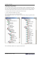
The VirtualPlatform.fmx tree view is shown in two parts below, with ports expanded to show
all connections.
The VirtualPlatform module is now complete and can be built.
56 CoMET Version 5.9 – Tutorial
CIF Module - SimpleVSP
Building the VirtualPlatform
The VirtualPlatform must be built before it is added to the VSP. CoMET extracts
information about module structure from the built .dll file, so the module .dll must exist
before you add a module instance to another project.
Ensure VirtualPlatform is the active project. The active project is displayed in bold. If
VirtualPlatform is not the active project, activate it as follows.
Activating the Project to be Built
In the Workspace Window, right click on the VirtualPlatform project node
Select Activate Project from the context menu.
Alternatively select the Virtual Platform project node and press Ctrl-A
CoMET Version 5.9 – Tutorial
57
CIF Module - SimpleVSP
Building a Project
Choose Workspace/Build, or click the tool bar Build button
The Output Window, Build tab shows messages as the project is built.
The messages indicate the cause of any problems that prevent a successful build.
58 CoMET Version 5.9 – Tutorial
CIF Module - SimpleVSP
Adding a VirtualPlatform Module Instance to the VSP
We now add and instance of the VirtualPlatform module to the SimpleVSP1 module. In the
example below we add the module instance without using the Modules Window. An
alternative is to first create a new module library containing the VirtualPlatform module (see
CoMET User Guide, Getting Started, Modules Configuration Settings), and then use the
methods already shown to add the VirtualPlatform from the Modules Window.
Adding a Module Instance using the Module Instance Dialog
Open SimpleVSP1.fmx , XML Tree View
Right click on the Module Instances node.
From the Module Instances context menu, choose Add Module Instance
CoMET Version 5.9 – Tutorial
59
CIF Module - SimpleVSP
Fabric Module dialog, Module Instance tab
Instance Name: Type VirtualPlatform1. The name for your new instance of the
VirtualPlatform module should begin with an alphabetic character, contain no spaces, and
follow the standard C naming convention. This name is used to form the names of
automatically generated functions in the source code CoMET creates for the module instance.
Module Type: In the list box, select VirtualPlatform. The list contains any module
types you create yourself, as well as module types from the VaST library.
Description: The VSP contains a single instance of the
VirtualPlatform, which in turn contains all other Module
Instances
For other fields accept defaults.
Fabric Module dialog: click OK.
60 CoMET Version 5.9 – Tutorial
CIF Module - SimpleVSP
The SimpleVSP1.fmx file now contains VirtualPlatform1, an instance of the VirtualPlatform
module type.
The VirtualPlatform1 module instance shows the ports we created earlier. We now add the
clock and reset to the SimpleVSP and connect them to the VirtualPlatform instance ports.
Adding Clock and Reset to SimpleVSP
Referring to the SimpleVSP Project Block Diagram, page 23, we now need to add to
SimpleVSP an instance of VastGpClock and an instance of VastGpReset. These are both in
the VaST modules library, and can be added from the Modules window using the methods
described in Adding Module Instances to the Virtual Platform, page 32.
Add an instance of VastGpClock to SimpleVSP1
Add an instance of VastGpReset to SimpleVSP1
The SimpleVSP1.fmx XML Tree view now shows the three module instances in
SimpleVSP1.
CoMET Version 5.9 – Tutorial
61
CIF Module - SimpleVSP
Connecting the SimpleVSP Module Instances
We now connect the module instance ports. Because the modules are on the same level, we
must create nets to connect the ports. For the steps below use the appropriate methods for
adding nets and connecting ports described in Adding Nets and Port Connections, page 43.
Add to SimpleVSP1 the net ClockNet, of type StdClock. Add the Description: This
connects the VSP Clock to the VirtualPlatform PlatformClock
port.
Add to SimpleVSP1 the net ResetNet, of type StdLogic. Add the Description: This
connects the VSP Reset to the VirtualPlatform PlatformReset
port.
Connect net ClockNet to VastGpClock1, Clock Port
Connect net ClockNet to VirtualPlatform1, PlatformClock
Connect net ResetNet to VastGpReset1, Reset Port
Connect net ResetNet to VirtualPlatform1, PlatformReset
The SimpleVSP1.fmx, XML Tree view shows the nets and port connections.
The VirtualPlatform1 module instance shows a Parameter Override for the
NumberOfMemoryBlocks parameter we created for the VirtualPlatform module. If at some
62 CoMET Version 5.9 – Tutorial
CIF Module - SimpleVSP
stage we want to alter the number of memory blocks we can do it at this level. For this
tutorial, using this VPM, the default number of memory blocks is correct.
We can now build the SimpleVSP module, generate a Prototype Parameter Configuration
file, and modify it to suit our specific VPM.
Modifying Module Instance Parameters
The Prototype Configuration (.pcx) file, or Platform Configuration file, contains override
parameters for the module instances in the project.
Generating the Prototype Parameter (Platform) Configuration file
Ensure that SimpleVSP1 is the active project. See Activating the Project to be Built, page
57
Choose Workspace/Build, or click the tool bar Build button
The Output Window, Build tab shows messages as the project is built.
CoMET Version 5.9 – Tutorial
63
CIF Module - SimpleVSP
One message indicates that CoMET has built the platform config (Prototype Configuration)
file.
Editing the Prototype (Platform) Configuration file
This file can now be edited to suit our specific VPM.
To open the Prototype Configuration file, click the tool bar Open Config File button down
arrow, and select SimpleVSP1.pcx
The .pcx file is an XML file and can be viewed in XML Tree View, or in parameter views.
The tree view shows that the .pcx file mirrors the structure of the .fmx file, with a node for
each parameter you can modify.
SimpleVSP1.pcx file contains a module instance for each Module Instance it contains, and
for each Module Instance contained by its child Module Instances and theirs, recursively.
For every Module Instance in the .pcx file, there are Parameter Override elements
corresponding to the Parameters in the module from which the Module Instance derives.
The .pcx Parameter Override Values take precedence over values specified for Module
Parameters or Module Instance Parameter Overrides upstream. This allows you to control the
behavior of the VSP by specifying all parameter values in the .pcx file.
64 CoMET Version 5.9 – Tutorial
CIF Module - SimpleVSP
The VirtualPlatform GenericMemory1 array size is specified by the
NumberOfMemoryBlocks parameter, so the .pcx file shows three GenericMemory1 elements.
CoMET Version 5.9 – Tutorial
65
CIF Module - SimpleVSP
We can now edit the start address and memory size of these blocks to suit our VPM. This is
conveniently done in Memory Parameter view.
Open SimpleVSP1.pcx in Memory Parameter view (right click on a line and select
Memory Parameter View from the context menu)
The appropriate memory block start and size addresses for the ARM926EJS processor are:
• GenericMemory[0]: Start 0, Size 8*M (reset vector)
• GenericMemory[1]: Start 0xA0000000, Size 64*M (code)
• GenericMemory[2]: Start 0xE0000000, Size 1*M (data)
Values may differ for other VPMs.
To edit the parameter, click in the required cell, then click again to open it in edit mode.
Edit the values for StartAddress and MemorySize as required.
The next step is to add the target code.
66 CoMET Version 5.9 – Tutorial
CIF Module - SimpleVSP
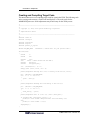
Creating and Compiling Target Code
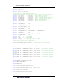
This tutorial does not cover compiling target code for a particular VPM. The following code
writes a string to the memory, reads it back and displays it. The code works for the
ARM926EJS processor. Some adjustments may be necessary for the VPM you use.
/*
**----------------------------------------------------------------------------**
** Copyright (c) 2004, VaST Systems Technology Corporation.
**
** SimpleVSP Hello World
**
**----------------------------------------------------------------------------*/
#include <stdio.h>
#include <string.h>
#include "vastdef.h"
#include "tspi.h"
#include "printf_to_tspi.h"
#define EXT_MEM_BASE
0x00180000 /* define this for your specific VPM */
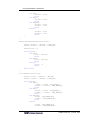
int main(void)
{
tWord8
i;
tWord8
cnt;
tWord32
char
tWord32
tWord32
*ptr;
*hello = "Hello World from the VPM.";
data[100];
check_data[100];
cnt = (strlen(hello) / 4) + 1;
memcpy((char *)data, hello, cnt * 4);
printf("SimpleVSP: Writing data \"%s\" to memory on the bus.\n", hello);
ptr = (tWord32 *) EXT_MEM_BASE;
for ( i = 0; i < cnt; i++ )
{
*ptr++ = data[i];
}
printf("SimpleVSP: Reading data from memory on the bus.\n");
ptr = (tWord32 *) EXT_MEM_BASE;
for ( i = 0; i < cnt; i++ )
{
check_data[i] = *ptr++;
}
printf("SimpleVSP: Data is \"%s\".\n", (char *)check_data);
if (strcmp((char *)check_data, hello) != 0)
printf("*** Demo failed: Unexpected data read from memory.\n");
else
printf("*** Demo worked. ***\n");
TspiVpmStop();
}
CoMET Version 5.9 – Tutorial
67
CIF Module - SimpleVSP
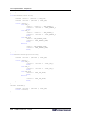
/* define any additional handers required for your specific VPM */
/*****************************************************/
/* Empty IRQ & FIQ handlers called from crt0
*/
/*****************************************************/
void irq_handler(void)
{
}
void fiq_handler(void)
{
}
/* bottom of file */
This code uses the TSPI (Target Software Programming Interface) to allow use of the
standard C stdout facility from within target software. For more details on TSPI see VaST
Target Software Programming Interface Functions For Register-Level Virtual Processor
Models User Guide.
Your VPM may have a number of different requirements, such as a different memory base
and different requirements for handlers.
Adjust the code to suit your VPM.
Compile it and generate a binary image.
For the ARM family of processors CoMET can integrate compiling and editing target code as
projects within the SEE.
68 CoMET Version 5.9 – Tutorial
CIF Module - SimpleVSP
Adding a Target Image
We now add the target image to the SimpleVsp1 project.
In the Workspace Window, right click SimpleVSP1/Target Test and choose Add Target
Image from the context menu.
CoMET displays the Project dialog, Properties tab.
Project dialog, Target Image tab, Properties panel:
Rvpm Instance: Select the VPM you are using
Reader: Select the appropriate binary reader for the target image you created
Path: Browse for the target image you created
Map: Default is appropriate.
CoMET Version 5.9 – Tutorial
69
CIF Module - SimpleVSP
Project dialog: Click OK.
The target image node appears under the Target Test node.
Simulating SimpleVSP1
We have built a VSP with target code. We can now simulate it.
Ensure that SimpleVSP1 is the active project. See Activating the Project to be Built, page
57
Choose Workspace/Simulate or click the Simulate button
CoMET builds the project if necessary. There may be dialogs requiring confirmation.
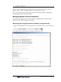
After building the project, CoMET runs the simulation. The Output Window, Software tab,
shows messages and output from the project.
On completion of the simulation, the SimpleVSP1 project has written a string to memory,
read it back and displayed the output.
CoMET reports the number of instructions executed, the number of cycles simulated, and the
time for execution in simulated time and real time.
70 CoMET Version 5.9 – Tutorial
CIF Module - SimpleVSP
Unconnected Ports
When you run a project, CoMET checks the integrity of the model. It reports any errors it
finds. For example unconnected StdBus Ports are not permitted. If CoMET finds an
unconnected StdBus port it displays the error
You can find unconnected ports using the XML Tree View, the Fmx Report or the
Connection views. The Fmx Report lists unconnected Ports and Nets in the Errors and
Warnings section.
Follow the Unconnected Net link to see the connections for the Net:
In the example above we have forgotten to connect the StdLogic0Net to the StdLogic01
module instance Signal Out Instance Port.
CoMET Version 5.9 – Tutorial
71
CIF Module - SimpleVSP
Debugging a Simulation
CoMET allows you to debug both target code and hardware modules during a simulation.
This tutorial does not cover coding modules or writing target code. However we can
demonstrate placing a breakpoint in the SimpleVSP1 skeleton code. When you run the
simulation in debug mode execution stops at the breakpoint, allowing you to step through
execution.
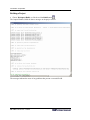
In the Workspace Window, double click SimpleVSP1/Folders/Source Files/SimpleVSP1.c to
open SimpleVSP1.c in the Document Window.
Locate the function SimpleVSP1InitModuleInstance.
Place the cursor on the line:
return AmpiSUCCESS;
Click the tool bar Toggle Breakpoint button or press F9.
A red diamond breakpoint icon appears beside line in the SimpleVSP1.c Document Window.
You can toggle the breakpoint off with the same button, or remove all breakpoints with the
Remove all breakpoints button beside it.
Click the tool bar Start Debugging icon or press F5
CoMET may display dialogs requiring confirmation of build options. CoMET then displays
the Debug Options dialog.
72 CoMET Version 5.9 – Tutorial
CIF Module - SimpleVSP
Debug Options dialog.
H/W Model: Choose Debug
ARM926EJS (or other VPM): Choose Simulate
Click OK
CoMET executes the simulation until it reaches the breakpoint in SimpleVSP1.c. It then
pauses execution. The Debug Step buttons are now active. You can Step into the highlighted
block, Step over it, or Step out of it.
In this example there is little else to see, but useful debug information can be obtained by
following execution in more complex module functions.
Click the Continue debugging icon to continue the simulation until the next breakpoint.
Click the tool bar Stop debug/simulate button to end the debug simulation.
CoMET Version 5.9 – Tutorial
73
CIF Module - SimpleVSP
Obtaining a Value Change Dump
The standard VCD format output is a useful tool for analysis. To obtain a VCD:
Choose Tools/VCD Configuration
Check Enabled and specify the Location of the vcd file to be saved.
Enabling Bus Monitoring
CoMET by default dumps all port and net changes to the VCD file, however no bus
information is dumped unless bus monitoring is enabled.
The interesting events in our simulation happen on the bus, so we wish to enable bus
monitoring.
Open SimpleVSP1.pcx in XML Tree View
Double click SimpleVSP1/Module Instances/ Top/VirtualPlatform1/StdBus1/Bus
Monitor
Platform Config dialog, Parameter Override tab, Properties panel:
Override value: select Enabled
Platform Config dialog: Click OK
74 CoMET Version 5.9 – Tutorial
CIF Module - SimpleVSP
The SimpleVSP1.pcx displays the BusMonitor parameter with value Enabled. Bus signals
will appear in the VCD.
Run the simulation.
CoMET generates the VCD and writes it to the location you specified.
CoMET Version 5.9 – Tutorial
75
CIF Module - SimpleVSP
Analyzing the VCD
Events such as the reset and memory reads can be identified. Any VCD viewer or analysis
tool can be used. The pictures below are obtained using SignalScan.
Reset
Read string back from memory
76 CoMET Version 5.9 – Tutorial
CIF Module - SimpleVSP
Obtaining a Metrix Trace
If you have the Metrix option, you can create a Metrix Configuration (.mcx) file to view
VPM trace and StdBusProbes and StdLogicProbes. See the Metrix Configuration File User
Guide. A suitable mcx setup is shown below.
CoMET Version 5.9 – Tutorial
77
CIF Peripheral Model - SimpleTimer
Overview
This tutorial demonstrates to how construct a Peripheral Model and how to write the code
that models the device behavior.
The device is a 32 bit general purpose timer. The details are given in the specification below.
This tutorial demonstrates:
• Creating a CIF Peripheral Device project
• Setting up the Fabric Module Definition (.fmx) file
• Setting up instance data
• Configuring the initialization function
• Connecting the peripheral device to a StdBus net
• Reading and writing events
• Scheduling callbacks
• Instantiating the device in a platform
Prerequisites
This tutorial assumes:
Comet 5 is installed and open.
Either the Microsoft Visual C++ compiler or the gcc compiler is installed
You are familiar with creating and navigating a workspace. These procedures are
covered in the preceding Hello World example
You are familiar with creating a CIF project. This is covered in the Simple VSP
tutorial above.
CoMET Version 5.9 – Tutorial
79
CIF Peripheral Model - SimpleTimer
You are familiar with viewing and editing an .fmx file. This is covered in the Simple
VSP tutorial above.
You have completed the SimpleVSP tutorial and have the SimpleVSP workspace
available to add the SimpleTimer project.
You are familiar with writing and building target code for the microprocessor you will
use in this tutorial. Alternatively it is assumed you have access to someone who can
build the tutorial target code and provide a binary image.
80 CoMET Version 5.9 – Tutorial
CIF Peripheral Model - SimpleTimer
Specification
•
The SimpleTimer is a 32 bit general purpose timer
•
The SimpleTimer has two general purpose match registers
•
Each match can be individually enable and disabled
•
Each match event can generate an interrupt
•
The interrupts for each match can be disabled and enabled
•
The current timer value can be written at any time from the bus
•
Each interrupt shall have its own flag
•
The match registers shall cause a match only when the counter value equals the match
register value and the match is enabled
•
The match interrupt associated with a match shall stay high until it is explicitly cleared
•
The timer shall clear all registers upon a reset (effectively disabling the counter and
interrupts)
SimpleTimer Diagram
SimpleTimer Device
Bus
BusClock
GTR - General Timer Register
MTR1 - Match Timer Register 1
MatchInterrupt1
MTR2 - Match Timer Register 2
TER - Timer Enable Register
TIER - Timer Interrupt Enable Register
MatchInterrupt2
TimerClock
TIFR - Timer Interrupt Flag Register
Reset
The SimpleTimer device
CoMET Version 5.9 – Tutorial
81
CIF Peripheral Model - SimpleTimer
Registers
The SimpleTimer requires registers to enable and configure the timer, as well as provide a
mechanism for the embedded target software to communicate with the device. The timer has
the following registers:
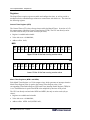
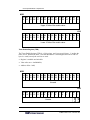
General Timer Register (GTR)
The General Timer (GT) is the reference timer used by the Match Timers. It consists of a 32bit counter register called the General Timer Register (GTR). The CPU can directly read or
write the GTR, but only as an entire word (4-byte value).
Register is readable and writeable
Value after reset = 0x00000000;
Address offset: 0x00;
MSB
Bit Bit Bit Bit Bit Bit Bit Bit Bit Bit Bit Bit Bit Bit Bit Bit
31 30 29 28 27 26 25 24 23 22 21 20 19 18 17 16
Upper 16 bits of the free running counter value
LSB
Bit Bit Bit Bit Bit Bit Bit Bit Bit Bit Bit Bit Bit Bit Bit Bit
15 14 13 12 11 10 9
8
7
6
5
4
3
2
1
0
Lower 16 bits of the free running counter value
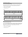
Match Timer Registers (MTR1 and MTR2)
Each Match Timer Register is a 32-bit compare timer, which generates an interrupt when the
Match Timer Register value is equal to the General Timer Register value, if the
corresponding Timer Enable Register (TER) and Timer Interrupt Enable Register (TIER) bit
is set. The Match time is equal to the MTR value multiplied by the timer clock period.
The CPU can directly read and write MTR1 and MTR2, but only as entire words (4-byte
values).
Registers are readable and writeable
Value after reset = 0x00000000;
Address offset: MTR1: 0x28, MTR2: 0x30;
82 CoMET Version 5.9 – Tutorial
CIF Peripheral Model - SimpleTimer
MSB
Bit Bit Bit Bit Bit Bit Bit Bit Bit Bit Bit Bit Bit Bit Bit Bit
31 30 29 28 27 26 25 24 23 22 21 20 19 18 17 16
Upper 16 bits of the match value
LSB
Bit Bit Bit Bit Bit Bit Bit Bit Bit Bit Bit Bit Bit Bit Bit Bit
15 14 13 12 11 10 9
8
7
6
5
4
3
2
1
0
Lower 16 bits of the match value
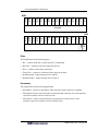
Timer Enable Register (TER)
The Timer Enable Register (TER) is a 2-bit register, one bit per special timer: ‘1’ enables the
timer, and ‘0’ disables the timer. Note that the address is word-aligned and can be read as a
byte or a word, but only the two bits are used.
Register is readable and writeable
Value after reset = 0x00000000;
Address offset: 0x08;
MSB
Bit Bit Bit Bit Bit Bit Bit Bit Bit Bit Bit Bit Bit Bit Bit Bit
31 30 29 28 27 26 25 24 23 22 21 20 19 18 17 16
Unused
LSB
Bit Bit Bit Bit Bit Bit Bit Bit Bit Bit Bit Bit Bit Bit Bit Bit
15 14 13 12 11 10 9
8
7
6
5
4
3
2
1
0
CoMET Version 5.9 – Tutorial
TER1
TER2
Unused
83
CIF Peripheral Model - SimpleTimer
Timer Interrupt Enable Register (TIER)
The Timer Interrupt Enable Register (TIER) is a 2-bit register, one bit per special timer: ‘1’
enables the timer interrupt, and ‘0’ disables the timer interrupt. Note that the address is
word-aligned and can be read as a byte or a word, but only the two bits are used.
Register is readable and writeable
Value after reset = 0x00000000;
3. Address offset: 0x10;
MSB
Bit Bit Bit Bit Bit Bit Bit Bit Bit Bit Bit Bit Bit Bit Bit Bit
31 30 29 28 27 26 25 24 23 22 21 20 19 18 17 16
Unused
LSB
Bit Bit Bit Bit Bit Bit Bit Bit Bit Bit Bit Bit Bit Bit Bit Bit
15 14 13 12 11 10 9
8
7
6
5
4
3
2
1
0
TIER1
TIER2
Unused
Timer Interrupt Flag Register (TIFR)
The Timer Interrupt Flag Register (TIFR) is a 2-bit register, one bit per special timer. A bit is
set to ‘1’ if its corresponding timer generates an interrupt. This register is a read-modify-write
register. Write a 0 to the particular bit to clear the interrupt. Note that the address is wordaligned and can be accessed as a byte or a word, but only Bits 0 and 1 are used.
Register is readable and writeable
Value after reset = 0x00000000;
Address offset: 0x18;
84 CoMET Version 5.9 – Tutorial
CIF Peripheral Model - SimpleTimer
MSB
Bit Bit Bit Bit Bit Bit Bit Bit Bit Bit Bit Bit Bit Bit Bit
31 30 29 28 27 26 25 24 23 22 21 20 19 18 17
Bit
16
Unused
LSB
Bit Bit Bit Bit Bit Bit Bit
15 14 13 12 11 10 9
Bit Bit
8
7
Bit
6
Bit Bit Bit
5 4
3
Bit Bit Bit
2
1
0
TIFR1
TIFR2
Unused
Ports
The SimpleTimer has the following ports:
• Bus – connects to the bus on which the timer is instantiated
• BusClock – connects to the clock input from the bus
• Reset – connects to the system reset input
• TimerClock – connects to a dedicated clock input for the timer
• MatchInterrupt1- output interrupt line for match 1
• MatchInterrupt2 – output interrupt line for match 2
Parameters
The SimpleTimer has the following parameters:
• StartAddress - the device start address from which the register offsets are calculated
• Timing/Read - latency associated with accessing the timer on the bus for a read operation,
expressed in number of ticks of the bus clock
• Timing/Write - latency associated with accessing the timer on the bus for a write
operation, expressed in number of ticks of the bus clock
CoMET Version 5.9 – Tutorial
85
CIF Peripheral Model - SimpleTimer
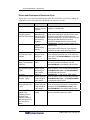
Event Responses for SimpleTimer
From the specification we can prepare the following table of events and the corresponding
responses.
Event
Response
Reset
Deassert outputs, clear all registers
MTR (Match Timer Register) equal to
General Timer register
Corresponding MatchInterrupt Port goes high
if Match Enabled and Interrupt Enabled
Bus Read
Return value of register determined by
address
Bus Write GTR General Timer Register
General Timer Register set to new value
Bus Write Match Timer Register n (MTRn)
MTRn set to value.
Bus Write Timer Enable Register (TER)
Enable or disable MTRn depending on value
written
Bus Write Timer Interrupt Enable Register
(TIER)
Enable or disable interrupt n depending on
value written
Unmatch (MTR (Match Timer Register) equal
to General Timer register). Note that this
takes place one click tick after a Match.
Respond to Match no longer true. Interrupt
stays high.
86 CoMET Version 5.9 – Tutorial
CIF Peripheral Model - SimpleTimer
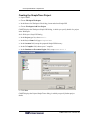
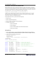
Creating the SimpleTimer Project
Open CoMET
Choose File/Open Workspace
In the Browse for Workspace files dialog, locate and select SimpleVSP
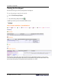
Choose Workspace/Add New Project
CoMET displays the Workspace:SimpleVSP dialog, in which you specify details of a project
in the Workspace.
In the Workspace:SimpleVSP dialog:
In the Project type list, select Fabric
In the Project Name field, type SimpleTimer
In the Location field, accept the proposed SimpleVSP directory
In the C Compiler field, choose your C compiler.
In the Simulator or Execution Engine field, accept VaST Nova 2
Click Next
CoMET displays the Project:SimpleTimer dialog, in which you specify further project
details.
CoMET Version 5.9 – Tutorial
87
CIF Peripheral Model - SimpleTimer
Project: SimpleTimer dialog:
In the Module Class field, choose Peripheral Model.
In the Module Type field, accept SimpleTimer.
In the Version field, accept 1.0.0
Click Finish
88 CoMET Version 5.9 – Tutorial
CIF Peripheral Model - SimpleTimer
Editing the SimpleTimer fmx file
CoMET creates a CIF Peripheral Model project from templates. It displays the newly created
.fmx file for the SimpleTimer in the Document window.
To display the .fmx file at any time
In the Workspace window, open the SimpleTimer project/Folders/Source Files folder.
Double-click the SimpleTimer.fmx file.
CoMET opens the fmx file in the Document window.
Ensure that the fmx file is displayed in XML Tree view.
Right click on the fmx file SimpleTimer node and choose Expand Fabric Module to display
all nodes in the tree.
From the Peripheral Model templates CoMET has created source files and header files. From
the fmx template CoMET has created an fmx file with default Parameters, Ports, a Task, and
Task/Port Or Net Views for the Ports.
CoMET Version 5.9 – Tutorial
89
CIF Peripheral Model - SimpleTimer
Adding Ports
Ports provide the input to and output from the Peripheral Mode. The required Bus, BusClock
and Reset ports are created by default. Add the following ports:
Name
Type
Direction
Description
MatchInterrupt1
StdLogic
Output
Output interrupt line for match 1
MatchInterrupt2
StdLogic
Output
Output interrupt line for match 2
TimerClock
StdClock
Input
Connects to a dedicated clock input
for the timer
To add a port:
Right click the Ports node.
Choose Add Port from the context menu.
CoMET displays the Fabric Module dialog, Port tab. An example is shown below:
In the Fabric Module dialog, Port panel, Properties panel:
Name: specify the name of the port, e.g. MatchInterrupt1
Type: select the required Port Type, e.g.StdLogic
NumberOf: accept the default of 1.
Direction: Specify the required Port Direction: Input, Output, Input/Output. e.g. for
MatchInterrupt1, choose Output.
Description: Provide a brief description. This appears in the Fmx Prototype Report.
90 CoMET Version 5.9 – Tutorial
CIF Peripheral Model - SimpleTimer
The fmx file shows the ports as follows.
Adding Tasks
Tasks handle the initialization, execution flow, and destruction of the module instance. Most
peripheral models have a single task which initializes and then suspends indefinitely. After
initialization, callbacks handle execution.
CoMET automatically creates one task for a new CIF Peripheral Model project.
Adding a PortOrNetView
For task behavioral code to have access to a Port, the port must be associated with the Task
via a PortOrNetView.
When the New Project wizard creates a CIF Peripheral Model, it creates default Ports, a
single Task and a PortOrNetView for each default Port. CoMET has created a
PortOrNetView for the BusClock, Bus and Reset ports. We have to add a PortOrNetView for
each of the remaining Ports.
CoMET Version 5.9 – Tutorial
91
CIF Peripheral Model - SimpleTimer
Add the following PortOrNetView elements to the fmx file.
Name
Type
MatchInterrupt1
Master
MatchInterrupt2
Master
TimerClock
Slave
To add a PortOrNetView
Right click on the Task/Port Or Net Views node in the fmx file.
Select Add Port Or Net View from the context menu.
CoMET displays the Fabric Module dialog, Port Or Net View tab.
Fabric Module dialog, Port Or Net View tab, Properties panel.
Name: Select the required Port
Type: Select the required view type: Slave, Master, MasterSlave, Controller. e.g. for the
MatchInterrupt1 Port, select Type Master.
Number Of: Accept default of 1
Description: Add a description if you wish.
When the required PortOrNetView elements are added, the corresponding part of the fmx
XML Tree view is as follows:
92 CoMET Version 5.9 – Tutorial
CIF Peripheral Model - SimpleTimer
Adding Behavioral Code
We now implement the behavioral code associated with the Simple Timer device. In this
section we discuss the recommended methodology and implementation details for the
behavioral code.
General Modeling Guidelines
In designing VaST models we aim for speed and accuracy. The model should accurately
model the hardware. It should execute as efficiently as possible, to save real time when
simulating. A model should display the behavior of the modeled hardware device only at the
times when it is observed. When it is not observed, it should do as little as possible. This
improves efficiency and performance without sacrificing accuracy.
The times when the model is observed are at events such as the following:
Register reads - when a register is read, its value must correspond to the expected register
value. For example, the GTR (General Timer Register) should indicate the correct tick count.
Register writes - when we write to a register, the result should correspond to the expected
result. For example, writing a zero to bit 0 or 1 in the TER (Timer Enable Register) should
disable the corresponding MTR (Match Timer Register).
Events - when an event takes place, such as a change in a Net or Port, or a specified time
event, the model should behave as expected. For example, a Match event should result in the
MatchInterrupt port going high.
Events and Callback Functions
It is efficient to use CIF callback functions to respond to events. An event callback function
executes only when the corresponding event takes place.
Below we show the Event and Response table prepared from the specification. We add a
column describing the associated behavioral code function.
State and Instance Data
The model state is managed in an instance data structure. Typically the instance data structure
is defined in the projectName.h file and initialized in the task initialization function in the
projectName.c file.
How the SimpleTimer Behavior is Implemented
The SimpleTimer follows the above modeling guidelines. The implementation may differ
from expectation based on hardware experience.
Determining General Timer Register Value
While it may be traditional for a hardware timer to respond to each clock tick, updating the
counter for each tick, this is inefficient in a model. We need to know the correct value for the
counter only when we read it or write to it. We can use a function call to determine how
many ticks have elapsed since the TimerClock started, so there is no need to count ticks.
CoMET Version 5.9 – Tutorial
93
CIF Peripheral Model - SimpleTimer
Consequently, the code modeling the GTR (General Timer Register) behavior calculates and
updates the counter at the time of read or write. The tick count at the last time the counter was
updated is tracked in an instance variable, LastCounterUpdateTime. The
AmpiClockGetTicks function is used to determine the number of clock ticks since the clock
started. The LastCounterUpdateTime holds timer clock tick count at the last update. When
the GTR register is updated, the LastCounterUpdateTime is updated with the current
TimerClock count. The example below is from the WriteRegister function in SimpleTimer.c.
Count = IP->regGTR + (tWord32)(AmpiClockGetTicks(IP->TimerClock, 0)
- IP->LastCounterUpdateTime);
//
Nothing to do if it hasn't changed.
if (Count != Data)
{
//
Save the new counter value.
IP->regGTR = Data;
IP->LastCounterUpdateTime = AmpiClockGetTicks(IP->TimerClock,
0);
Determining When a Match Occurs
To determine whether a match has occurred, we could check the value of the counter value
against the match register value at each tick. However this is inefficient in a model. We are
simulating with a scheduler. We simply tell the scheduler when the next match will occur,
determined by the value in the match register and the value in the timer register. To do this
we schedule a callback function.
The time at which the callback function is scheduled is calculated on the basis of the GTR
(General Timer Register) value, the MTR (Match Timer Register) value that is to match it,
and the TimerClock.
The details are in the function SetupNextMatch in SimpleTimer.c. The GTR Count is
calculated as shown above. Then the time to the next match is calculated as follows:
if (IP->regMTR[MTR_ix] > Count)
MatchTicks = IP->regMTR[MTR_ix] - Count;
else
MatchTicks = (tWord32)(ULL(0x100000000) + IP->regMTR[MTR_ix] Count);
The callback is then scheduled as follows:
AmpiTaskScheduleCallbackTicksAfterSync(IP->MatchEvent[MTR_ix],
MatchTicks, 0)
It is now up to the scheduler to call the SimpleTimer when the event occurs. Meanwhile the
SimpleTimer remains idle. To set up callback functions, we have to
• create the functions
• declare handles for the callback functions
• create callback data structures
• register the callback functions in the SimpleTimerInitTaskInstance function.
94 CoMET Version 5.9 – Tutorial
CIF Peripheral Model - SimpleTimer
The CIF Peripheral Model Template
The SimpleTimer project source files are created from the CIF (Communications and
Infrastructure Fabric) Peripheral Model template. The template provides a general set of
functions and structure. We add code within the supplied template functions and structures,
and add additional functions for our specific callbacks and other requirements.
Template Functions
The table below shows functions supplied in the template. They are modified or unmodified
as shown.
Template Function
Event
Comment
Reset
Reset port
change
Modify to handle reset of
specific ports and registers
ReadRegister
Called by
BusRead
and
UntimedBus
Read
Modify to handle specific
registers and behavior
WriteRegister
Called by
BusWrite and
UntimedBus
Write
Modify to handle specific
registers and behavior
BusRead
Called on
read from
Bus port.
Unmodified. Handles StdBus
protocol 32 bit accesses with
4-byte width bus
transactions. This is suitable
for our model. Calls
ReadRegister.
BusWrite
Called on
write to Bus
port.
Unmodified. Handles StdBus
protocol 32 bit accesses with
4-byte width bus
transactions. This is suitable
for our model. Calls
WriteRegister
UntimedReadRegisterByByte
UntimedBusRead
Unmodified. Used by
debugger interface
Called on
untimed read
on Bus port
UntimedWriteRegister
Unmodified. Used by
debugger interface
Unmodified. Used by
debugger interface
UntimedBusWrite
Called on
untimed write
on Bus port
Unmodified. Used by
debugger interface
SimpleTimerInitModuleInstance
Module
Unmodified. Allocates the
CoMET Version 5.9 – Tutorial
95
CIF Peripheral Model - SimpleTimer
initialization
Instance Data structure and
stores the module id and
pathname in it.
SimpleTimerInitTaskInstance
Task
initialization
Modify to set up required
instance data and callback
data structures
SimpleTimerTaskFunction
Processing
commences
Unmodified. Simply
suspends. Behavior is
implemented with callbacks
InitDll
Unmodified empty function
stub
PreSymlinkInit
Unmodified
InitSymlink
Unmodified. Sets value of
pAmpiTaskId, used later by
macros.
UninitDll
Unmodified empty function
stub
Additional Callback and Helper Functions
Additional Function
Event
Comment
SetupNextMatch
Helper function
Set up callback functions for
Match events. Check TER,
TIER and TIFR registers and
do not proceed if interrupt
high or match or interrupt
disabled.
ClearMatchInterrupts
Helper function
Clear MatchInterruptPorts called by WriteRegister for
TER, TIER and TFR
Match
Match - GTR value
matches MTR1 value or
MTR2 value
Callback function, called
when a scheduled match
event takes place. This is
scheduled in the
SetupNextMatch function
Unmatch
UnMatch - GTR value
no longer matches
MTR1 value or MTR2
value
Callback function, called
when a scheduled unmatch
event takes place. This is
scheduled in the Match
function
96 CoMET Version 5.9 – Tutorial
CIF Peripheral Model - SimpleTimer
Events and Responses in Behavioral Code
We can now review the Event and Response table derived from the specification, adding the
information on how our behavioral code handles the response to events.
Event
Response
Behavioral Code Function
Reset
Deassert
outputs, clear all
registers
Reset - deassert output on entering reset, clear
registers on exiting reset
MTR (Match Timer
Register) equal to
General Timer register
Corresponding
MatchInterrupt
Port goes high if
Match Enabled
and Interrupt
Enabled
Match - callback, called when a scheduled
match event takes place. Set the GTR to show
the correct count, set the TIFR to show the
required interrupt flag, generate the interrupt by
changing the MatchInterrupt port value,
schedule an UnMatch event on the next tick.
Bus Read
Return value of
register
determined by
address
ReadRegister - Decode required register from
address offset.
Bus Write
GTR General Timer
Register
General Timer
Register set to
new value
WriteRegister - In the case of GTR (General
Timer Register) determine the value at the time
of the write. Call SetupNextMatch to reschedule
match events.
Bus Write
Match Timer Register
n (MTRn)
MTRn set to
value.
WriteRegister - Write value to MTR register,
cancel any scheduled callbacks and call
SetupNextMatch to reschedule match events.
Bus Write
Timer Enable Register
(TER)
Enable or
disable MTRn
depending on
value written
WriteRegister - In the case of TER change
value of register, clear corresponding interrupts
(ClearMatchInterrupts), call SetupNextMatch
to reschedule match events.
Bus Write
Timer Interrupt Enable
Register (TIER)
Enable or
disable interrupt
n depending on
value written
WriteRegister - In the case of TIER change
value of register, clear corresponding interrupts
(ClearMatchInterrupts), call SetupNextMatch
to reschedule match events.
Bus Write
Timer Interrupt Flag
(TIFR)
Enable or
disable interrupt
n depending on
value written
WriteRegister - In the case of TIFR change
value as required and deassert corresponding
interrupt ports (ClearMatchInterrupts). Call
SetupNextMatch to reschedule match events.
Unmatch (MTR
(Match Timer
Register) equal to
General Timer
register). Note that
this takes place one
click tick after a
Match.
Prepare for next
match
UnMatch - Callback scheduled by Match
function. Schedule next match event.
In the case of GTR (General Timer Register)
determine the value at the time of the read
CoMET Version 5.9 – Tutorial
97
CIF Peripheral Model - SimpleTimer
Declarations, Definitions and Instance Data
Instance data stores the state of a particular instance of a model. Each instance of a Simple
Timer device needs to maintain its own state, while all instances of a device share behavioral
code. State is maintained in the instance data structure. This structure is defined in the header
file SimpleTimer.h. This file can be found in the CoMET workspace:
SimpleTimer/Folders/Header Files/SimpleTimer.h
CoMET creates a default SimpleTimer.h file from a template when the project is created.
The SimpleTimer.h is the appropriate file in which to create #defines for register address
offsets and bit masks for manipulating registers.
In the SimpleTimer.h file we perform the following steps:
Define macros
Define Callback Data Structure
Declare Callback and Helper Function prototypes
In Instance data structure:
o Declare Port handles
o Declare Registers
o Declare Callback Handles and Callback Data Structure
o Declare state variables
Defining Macros
In the CoMET workspace, open the SimpleTimer/Folders/Header Files/SimpleTimer.h
file. To open the file in the Document window, double click on the workspace file name.
Add the following definitions, after the line:
#include "config.h"
and before the line
typedef struct sInstanceData tInstanceData;
CODE BEGINS
#define
NUM_MATCH_REGISTERS
/* SimpleTimer register offsets */
#define
GTR_OFFSET
0x00000000
#define
TER_OFFSET
0x00000008
#define
TIER_OFFSET
0x00000010
#define
MTR1_OFFSET
0x00000028
#define
MTR2_OFFSET
0x00000030
#define
TIFR_OFFSET
0x00000018
#define
#define
#define
#define
#define
#define
TER_ENABLE_1
TER_ENABLE_2
TER_ENABLE_ALL
TIER_ENABLE_1
TIER_ENABLE_2
TIER_ENABLE_ALL
98 CoMET Version 5.9 – Tutorial
2
/*
/*
/*
/*
/*
/*
General Timer Register */
Timer Enable Register */
Timer Interrupt Enable Register */
Match Timer Register 1 */
Match Timer Register 2 */
Timer Interrupt Flag Register */
0x01
0x02
(TER_ENABLE_1 | TER_ENABLE_2)
0x01
0x02
(TIER_ENABLE_1 | TIER_ENABLE_2)
CIF Peripheral Model - SimpleTimer
#define
#define
#define
TIFR_SET_1
TIFR_SET_2
TIFR_SET_ALL
0x01
0x02
(TIFR_SET_1 | TIFR_SET_2)
#define
#define
MATCH1_REGISTER 0 //array index
MATCH2_REGISTER 1 //array index
Defining the Callback Data Structure
Define the following data structure immediately after the typedef for the instance struct,
outside of the instance struct definition.
Add the following code immediately after the line:
typedef struct sInstanceData tInstanceData;
CODE BEGINS
/*
** Timer callback data structure.
*/
struct sTimerCallbackData
{
tInstanceData
*IP;
tWord32
MatchRegisterN;
};
typedef struct sTimerCallbackData tTimerCallbackData;
CODE ENDS
Adding the Callback and Helper Function Prototypes
At the end of the SimpleTimer.h file, immediately before the line:
#endif /* __SimpleTimer_H */
add the following code:
CODE BEGINS
/*
** Callback and helper function prototypes
*/
static
static
static
static
Mask);
void
void
void
void
Match(void *p);
Unmatch(void *p);
SetupNextMatch(tInstanceData *IP, const tInt32 MatchRegisterN);
ClearMatchInterrupts(const tInstanceData *IP, const tWord32
CODE ENDS
Declaring Instance Data Input and Output Port Handles
When creating the default SimpleTimer.h file, CoMET automatically creates Port handles for
the default Ports. These can be found within the sInstanceData structure.
CoMET Version 5.9 – Tutorial
99
CIF Peripheral Model - SimpleTimer
The default output section appears as follows:
/*
** Output handles
*/
/*
const tAmpiLogicHandleMaster
*/
*OutputName;
Replace the commented-out line
const tAmpiLogicHandleMaster
*OutputName;
with the following:
CODE BEGINS
const tAmpiLogicHandleMaster
*MatchInterrupt[NUM_MATCH_REGISTERS];
CODE ENDS
The default input handles section appears as follows:
/*
** Input handles.
*/
const tAmpiLogicHandleSlave
const tAmpiClockHandleSlave
const tAmpiStdBusHandleSlave
*Reset;
*BusClock;
*Bus;
• Add the TimerClock input port handle declaration after the line
const tAmpiStdBusHandleSlave
*Bus;
as follows:
CODE BEGINS
const tAmpiClockHandleSlave
*TimerClock;
CODE ENDS
Declaring Instance Data Registers
Registers are stored in the instance data structure as C variables of an appropriate type.
The default registers section looks similar to the following:
/*
** Registers Declarations
*/
tWord32 ReturnData;
Add the following register declarations after the line
tWord32 ReturnData;
CODE BEGINS
tWord32
tWord32
tWord32
tWord32
tWord32
100
regGTR; // General Timer Register
regTER; //Timer Enable Register
regTIER; //Timer Interrupt Enable Register
regTIFR; //Timer Interrupt Flag Register
regMTR[NUM_MATCH_REGISTERS]; // Match Timer Registers
CoMET Version 5.9 – Tutorial
CIF Peripheral Model - SimpleTimer
CODE ENDS
Declaring Instance Data Callback Handles and Callback Data Structures
Callback handles are used to register callback functions with the simulation engine. We will
use callbacks for match events (i.e. timer matches a match registers value) and unmatch
events (i.e. next callback after a match event, occurring on next clock tick).
Add the following declarations at the end of the instance data structure:
CODE BEGINS
/*
** Callback
*/
const tAmpiTaskCallbackHandle *MatchEvent[NUM_MATCH_REGISTERS];
const tAmpiTaskCallbackHandle *UnmatchEvent[NUM_MATCH_REGISTERS];
tTimerCallbackData
CallbackData[NUM_MATCH_REGISTERS];
CODE ENDS
Declaring Instance Data State Variables
State variables are used for instance specific data that is needed for the model code, but does
not represent something found in the real hardware. In this case we need to keep some
internal state about the TimerClock tick count at which the GTR register was set. This
supports the callback data structure.
The instance data structure by default contains a state data section that appears as follows:
/*
** States.
*/
tBoolean InReset;
Add the following state variable to the instance data structure in the state data section:
CODE BEGINS
tWord64
LastCounterUpdateTime;
CODE ENDS
Building the Project
At any time you can build the SimpleTimer project. The build process identifies any syntax
errors or other problems with code.
To build the project:
Click on the build button. Alternatively choose Workspace/Build or press Shift-F8.
CoMET Version 5.9 – Tutorial
101
CIF Peripheral Model - SimpleTimer
Creating the Behavioral Functions
We will add all behavioral code for the SimpleTimer device to the SimpleTimer.c file. This
file can be found in the Workspace at SimpleTimer/Folders/Source
Files/SimpleTimer.c.
Double click on the SimpleTimer.c node to open the file for editing in the Document
window.
The steps involved are:
• Create SetupNextMatch function
• Create ClearMatchInterrupts function
• Create Match callback function
• Create Unmatch callback function
• Modify Task Initialization function (AmpiTaskInitInstance)
• Modify Reset function
• Modify ReadRegister function and respond to various register reads
• Modify WriteRegister function and respond to various register writes
On creating the SimpleTimer project, the CoMET new project wizard creates a number of
default functions, named according to the project name. We also add helper and callback
functions.
Creating the SetupNextMatch, ClearMatchInterrupts, Match and UnMatch functions
These functions are fully commented. See also Events and Responses in Behavioral Code,
page 97. Add the following to the end of the SimpleTimer.c file:
CODE BEGINS
/*
**************************************************************************
**
** Helper and Callback Functions
*/
/**
**
SetupNextMatch(tInstanceData *IP, const tInt32 regMTRN)
**
**
Sets up a callback for the next match on the given match register.
** Any existing callbacks are cancelled.
**
** Parameters
**
IP
**
A pointer to the instance data.
**
**
regMTRN
**
The match register number, or -1 for all match registers.
*/
static void SetupNextMatch(tInstanceData *IP, const tInt32 MTR_ix)
{
/*
102
CoMET Version 5.9 – Tutorial
CIF Peripheral Model - SimpleTimer
**
Do nothing if in reset.
*/
if (IP->InReset)
return;
/*
**
If match register index is -1, set up all match registers.
**
Otherwise, set up the requested match register.
*/
if (MTR_ix == -1)
{
size_t j;
for (j = 0; j < lengthof(IP->MatchInterrupt); j++)
{
SetupNextMatch(IP, j);
}
} else if ( MTR_ix >= 0
&&
(tWord32)MTR_ix < lengthof(IP->MatchInterrupt)
)
{
tWord32 Count;
/*
**
Cancel any existing "match" events for the match register.
*/
AmpiTaskScheduleCallbackCancel(IP->MatchEvent[MTR_ix]);
/*
**
Cancel any existing "unmatch" events for the match register.
*/
AmpiTaskScheduleCallbackCancel(IP->UnmatchEvent[MTR_ix]);
/*
** If match interrupt is disabled OR
** match register is disabled OR
** match interrupt in Active
** Then do nothing
*/
if ( ((IP->regTIER & (1 << MTR_ix)) == 0
||
(IP->regTER & (1 << MTR_ix)) == 0
||
(IP->regTIFR & (1 << MTR_ix)) != 0)
)
return;
/*
** Calculate the current value of counter. IP->regGTR is
** updated only when the register is written or a match occurs.
*/
Count = IP->regGTR
+ (tWord32)(AmpiClockGetTicks(IP->TimerClock, 0)
- IP->LastCounterUpdateTime);
/*
**
Calculate time to next match.
*/
if (IP->regMTR[MTR_ix] == Count)
Match((void *)&IP->CallbackData[MTR_ix]);
else
{
tWord32 MatchTicks;
CoMET Version 5.9 – Tutorial
103
CIF Peripheral Model - SimpleTimer
if (IP->regMTR[MTR_ix] > Count)
MatchTicks = IP->regMTR[MTR_ix] - Count;
else
MatchTicks = (tWord32)(ULL(0x100000000)
+ IP->regMTR[MTR_ix]
- Count);
/*
**
Setup the timeout.
*/
AmpiTaskScheduleCallbackTicksAfterSync
(
IP->MatchEvent[MTR_ix],
MatchTicks,
0
);
}
}
}
/**
** void ClearMatchInterrupts(const tInstanceData *IP, const tWord32 Mask)
**
** Clears match interrupts corresponding to the given bit mask.
**
** Parameters
**
IP
**
A pointer to the instance data.
**
**
Mask
**
A bit mask of the match interrupts to be cleared.
*/
static void ClearMatchInterrupts(const tInstanceData *IP, const tWord32
Mask)
{
size_t j;
/*
**
Do nothing if in reset.
*/
if (IP->InReset)
return;
/*
**
Clear the match interrupts as per the Mask.
*/
for (j = 0; j < lengthof(IP->MatchInterrupt); j++)
{
if ((Mask & (1 << j)) != 0)
AmpiLogicWrite(IP->MatchInterrupt[j], StdLogicL);
}
}
/**
**
**
**
**
**
**
**
**
104
void Match(void *p)
Called as a scheduled callback when a timer match occurs and the
interrupt is enabled. This function drives the appropriate match
interrupt output high, sets the corresponding bit in the status
register and schedules a callback one tick later to schedule the
next match interrupt.
CoMET Version 5.9 – Tutorial
CIF Peripheral Model - SimpleTimer
** Parameters
**
p
**
Pointer to a tTimerCallbackData structure.
*/
static void Match(void *p)
{
tTimerCallbackData *pCallbackData = (tTimerCallbackData *)p;
tInstanceData *IP = pCallbackData->IP;
tWord32 regMTRN = pCallbackData->regMTRN;
/*
**
Do nothing if in reset.
*/
if (IP->InReset)
return;
/*
**
By definition of the match register, the count register
**
must equal the match register.
*/
IP->regGTR = IP->regMTR[regMTRN];
IP->LastCounterUpdateTime = AmpiClockGetTicks(IP->TimerClock, 0);
/*
**
Set the interrupt status bit.
*/
IP->regTIFR |= (1 << regMTRN);
/*
**
Generate the interrupt.
*/
AmpiLogicWrite(IP->MatchInterrupt[regMTRN], StdLogic1);
#ifdef _DEBUG
AmpiStreamPrintf(DEBUG_MSG,
"%s: Interrupt generated at TimerClock %#d\n",
IP->pModulePathName,IP->LastCounterUpdateTime);
#endif
/*
**
Set up a timed event (1 tick later) to clear the match flag.
*/
AmpiTaskScheduleCallbackTicksAfterSync(
IP->UnmatchEvent[regMTRN] , 1, 0);
}
/**
**
void Unmatch(void *p)
**
**
Called as a scheduled callback one clock tick after a timer match,
** this function schedules the next timer match callback.
**
** Parameters
**
p
**
Pointer to a tTimerCallbackData structure.
*/
static void Unmatch(void *p)
{
tTimerCallbackData *pCallbackData = (tTimerCallbackData *)p;
/*
**
Do nothing if in reset.
*/
if (pCallbackData->IP->InReset)
CoMET Version 5.9 – Tutorial
105
CIF Peripheral Model - SimpleTimer
return;
/*
**
Setup the next match.
*/
SetupNextMatch(pCallbackData->IP, pCallbackData->regMTRN);
}
CODE ENDS
Modifying the Task Initialization Function
The Task Initialization function runs once, after the Module Initialization function. In this
function we obtain and store handles, set up data structures and perform other initialization
functions.
Search for the function SimpleTimerInitTaskInstance.
To seach, choose Edit/Find or press Ctrl-F.
Get and store handles for master port views
The master ports are the interrupt ports the device will drive to request match interrupts.
Find the appropriate section in the task initialization function. The section is similar to the
following:
/*
** Get and store the handles for the Master Port views
** (for output ports).
** Again, we have only 1 task's views to store.
*/
/*
IP->OutputName = AmpiLogicInitMasterPortView("OutputName", "All");
*/
Add the following code, replacing the commented-out IP->OutputName lines:
CODE BEGINS
IP->MatchInterrupt[MATCH1_IX] =
AmpiLogicInitMasterPortView("MatchInterrupt1", "All");
IP->MatchInterrupt[MATCH2_IX] =
AmpiLogicInitMasterPortView("MatchInterrupt2", "All");
CODE ENDS
Get and store handles for slave port views
CoMET automatically generates code for the ports it creates by default: Bus, BusClock, and
Reset. The remaining slave port is the TimerClock port.
Find the appropriate section in the task initialization function. The section is similar to the
following:
/*
** Get and store the handles for the Slave Port views
** (for input ports).
** Again, we have only 1 task's views to store.
*/
106
CoMET Version 5.9 – Tutorial
CIF Peripheral Model - SimpleTimer
IP->BusClock = AmpiClockInitSlavePortView("BusClock", "All");
IP->Bus = AmpiStdBusInitSlavePortView("Bus", "All");
IP->Reset = AmpiLogicInitSlavePortView("Reset", "All");
Add the following after the IP->Reset line:
CODE BEGINS
IP->TimerClock = AmpiClockInitSlavePortView("TimerClock", "All");
CODE ENDS
Setup callback data structures
In the SimpleTimer.h instance structure we defined CallbackData, an array of
tTimerCallbackData structures, one for each match register. Here we initialize each structure.
After the slave port views input handles section, add the following:
CODE BEGINS
/*
** Set up callback data structures
*/
IP->CallbackData[MATCH1_IX].IP = IP;
IP->CallbackData[MATCH1_IX].regMTRN =
IP->CallbackData[MATCH2_IX].IP = IP;
IP->CallbackData[MATCH2_IX].regMTRN =
MATCH1_IX;
MATCH2_IX;
CODE ENDS
Register callback handles for match events
In the SimpleTimer.h instance structure we defined callback handle arrays, MatchEvent and
UnmatchEvent. Here we register the callback functions with the scheduler and store the
returned callback handles in the callback handle arrays.
The callback functions section looks similar to the following:
/*
**Register Callback functions if required for any other inputs
*/
In the callback functions section, add the following
CODE BEGINS
IP->MatchEvent[MATCH1_IX] = AmpiTaskRegisterCallback(Match,
(void *)&IP->CallbackData[MATCH1_IX], IP->TimerClock);
IP->MatchEvent[MATCH2_IX] = AmpiTaskRegisterCallback(Match,
(void *)&IP->CallbackData[MATCH2_IX], IP->TimerClock);
IP->UnmatchEvent[MATCH1_IX] = AmpiTaskRegisterCallback(Unmatch,
(void *)&IP->CallbackData[MATCH1_IX], IP->TimerClock);
IP->UnmatchEvent[MATCH2_IX] = AmpiTaskRegisterCallback(Unmatch,
(void *)&IP->CallbackData[MATCH2_IX], IP->TimerClock);
CODE ENDS
CoMET Version 5.9 – Tutorial
107
CIF Peripheral Model - SimpleTimer
Modify module and version information function
CoMET generates a call to print out model version information for the device.
The default section within the SimpleTimerInitTaskInstance function looks similar to the
following:
/*
** Display the module banner with version number.
*/
version = AmpiSymlinkGetVersionString();
AmpiStreamPrintf
(
INFO_MSG,
"\tVaST /*INSERT MODULE NAME IN FULL*/ %s\n",
version
);
Modify the AmpiStreamPrintf call as follows:
CODE BEGINS
AmpiStreamPrintf
(
INFO_MSG,
"\tVaST /*SimpleTimer*/ %s\n",
version
);
CODE ENDS
Modify Reset function
The Reset function, registered as a callback in the Task initialization function, is called every
time there is a change in the value of the Reset port. The default Reset function generated by
CoMET begins with a comment and function statement similar to the following:
/**
** Function:
**
void Reset(void *p)
**
** Description:
**
Resets the device on the rising edge of reset.
**
** Parameters:
**
p
**
Pointer to a tInstanceData structure.
**
** Returns:
**
Nothing.
*/
static void Reset(void *p)
{
CoMET generates a C switch with a case for each possible value of the Reset signal.
When Reset starts, we deassert the outputs and cancel callbacks. Modify the section case
StdLogicH to the following:
CODE BEGINS
108
CoMET Version 5.9 – Tutorial
CIF Peripheral Model - SimpleTimer
case StdLogicH:
/*
**
Deassert all outputs.
*/
IP->InReset = TRUE;
AmpiLogicWrite(IP->MatchInterrupt[MATCH1_IX], StdLogicL);
AmpiLogicWrite(IP->MatchInterrupt[MATCH2_IX], StdLogicL);
//
Cancel all "match" callbacks.
AmpiTaskScheduleCallbackCancel(IP->MatchEvent[MATCH1_IX]);
AmpiTaskScheduleCallbackCancel(IP->MatchEvent[MATCH2_IX]);
//
Cancel all "unmatch" callbacks.
AmpiTaskScheduleCallbackCancel(IP->UnmatchEvent[MATCH1_IX]);
AmpiTaskScheduleCallbackCancel(IP->UnmatchEvent[MATCH2_IX]);
break;
CODE ENDS
When Reset ends, we set the registers to their default states. Modify the section case
StdLogicL to the following:
CODE BEGINS
case StdLogicL:
if (IP->InReset)
{
/*
**
Leaving reset.
*/
IP->InReset = FALSE;
/*
**
Perform Reset Functions to Registers etc.
*/
//
Reset all the registers.
IP->regGTR = 0;
IP->regTER = 0;
IP->regTIER = 0;
IP->regTIFR = 0;
IP->regMTR[MATCH1_IX] = 0;
IP->regMTR[MATCH2_IX] = 0;
}
break;
CODE ENDS
Because we changed the value of the counter we need to save the current time for later
calculation of the counter value. Add the following immediately before the end brace of the
Reset function
IP->LastCounterUpdateTime = AmpiClockGetTicks(IP->TimerClock, 0);
Modifying the ReadRegister Function - Respond to Register Reads
The ReadRegister function begins with a comment and statement similar to the following:
/**
** Function:
** tWord32 ReadRegister(
**
tInstanceData *IP, const tWord32 Address, tBoolean Untimed)
**
CoMET Version 5.9 – Tutorial
109
CIF Peripheral Model - SimpleTimer
**
**
**
**
**
**
**
**
**
**
**
**
**
**
**
**
**
*/
Description:
Reads a device register. This function assumes that all registers
are 4-bytes in length. It also assumes that all the registers are
aligned on a 4-byte boundary.
Parameters:
IP
A pointer to the instance data.
Address
The address of the register to be read.
Untimed
Flag is true if this function is called by the Untimed read.
Returns:
The 32-bit value read from the register.
static tWord32 ReadRegister(tInstanceData *IP, const tWord32 Address,
tBoolean Untimed)
{
This function is called by the BusRead and BusUntimedRead functions. The ReadRegister
function is called each time there is a request to read data from a register. The value returned
is the value put on the bus.
CoMET by default creates code that calculates the address Offset and a switch statement that
processes the Offset. Note that when the GTR register is read, the value is calculated.
The code below contains debug output statements which appear only when the SimpleTimer
module is built in Debug configuration.
Modify the switch statement to appear as follows:
CODE BEGINS
case GTR_OFFSET:
Data = IP->regGTR + (tWord32)(AmpiClockGetTicks(IP->TimerClock, 0) IP->LastCounterUpdateTime);
#ifdef _DEBUG
AmpiStreamPrintf(DEBUG_MSG,
"%s: Read data %#06x from GTR\n",IP->pModulePathName,Data);
#endif
break;
case TER_OFFSET:
Data = IP->regTER;
#ifdef _DEBUG
AmpiStreamPrintf(DEBUG_MSG,
"%s: Read data %#06x from TER\n",IP->pModulePathName,Data);
#endif
break;
case TIER_OFFSET:
Data = IP->regTIER;
#ifdef _DEBUG
AmpiStreamPrintf(DEBUG_MSG,
"%s: Read data %#06x from TIER\n",IP->pModulePathName,Data);
#endif
break;
case TIFR_OFFSET:
110
CoMET Version 5.9 – Tutorial
CIF Peripheral Model - SimpleTimer
Data = IP->regTIFR;
#ifdef _DEBUG
AmpiStreamPrintf(DEBUG_MSG,
"%s: Read data %#06x from TIFR\n",IP->pModulePathName,Data);
#endif
break;
case MTR1_OFFSET:
Data = IP->regMTR[MATCH1_IX];
#ifdef _DEBUG
AmpiStreamPrintf(DEBUG_MSG,
"%s: Read data %#06x from MTR1\n",IP->pModulePathName,Data);
#endif
break;
case MTR2_OFFSET:
Data = IP->regMTR[MATCH2_IX];
#ifdef _DEBUG
AmpiStreamPrintf(DEBUG_MSG,
"%s: Read data %#06x from MTR2\n",IP->pModulePathName,Data);
#endif
break;
default:
if (!Untimed)
AmpiStreamPrintf(WARNING_MSG, "%s: Attempt to read from an
undefined register location 0x%lX\n", IP->pModulePathName, Address);
/*
**
Unknown register, just return a default value of 0.
*/
Data = 0;
break;
}
CODE ENDS
Modifying the WriteRegister Function - Respond to Register Writes
The WriteRegister function begins with a comment and statement similar to the following:
/**
** Function:
**
void WriteRegister(tInstanceData *IP, const tWord32
Address, const tWord32 Data)
**
** Description:
**
Writes a device register. This function assumes that
all the registers are
**
aligned to a 4-byte boundary.
**
** Parameters:
**
Address
**
The address of the register.
**
Data
**
The data to be written.
**
** Returns:
**
Nothing.
*/
static void WriteRegister(tInstanceData *IP, const tWord32 Address,
const tWord32 Data)
CoMET Version 5.9 – Tutorial
111
CIF Peripheral Model - SimpleTimer
{
This function is called by the BusWrite and BusUntimedWrite functions. The WriteRegister
function is called each time there is a request to write data to a register from the bus. This
function returns the value put on the bus. Often writing a register signifies the start of some
event in the device. Callback functions are frequently scheduled from the WriteRegister
function.
As in the ReadRegister function, we need to add the case statements to the switch for the
offset of the register write.
The code below contains debug output statements which appear only when the SimpleTimer
module is built in Debug configuration.
Modify the switch (Offset) statement in the WriteRegister function to the following:
CODE BEGINS
switch (Offset)
{
/*
** Determine the register from offset and take appropriate action
*/
case GTR_OFFSET : // General Timer Register
{
tWord32 Count;
#ifdef _DEBUG
AmpiStreamPrintf(DEBUG_MSG, "%s: Write data %#06x to GTR\n",IP>pModulePathName,Data);
#endif
//
Calculate current counter value.
Count = IP->regGTR + (tWord32)(AmpiClockGetTicks(IP->TimerClock, 0) IP->LastCounterUpdateTime);
//
Nothing to do if it hasn't changed.
if (Count != Data)
{
//
Save the new counter value.
IP->regGTR = Data;
IP->LastCounterUpdateTime = AmpiClockGetTicks(IP->TimerClock, 0);
//
Reschedule the next match events.
SetupNextMatch(IP, -1);
}
}
break;
case TER_OFFSET: // Timer Enable Register
#ifdef _DEBUG
AmpiStreamPrintf(DEBUG_MSG, "%s: Write data %#06x to TER\n",IP>pModulePathName,Data);
#endif
if (IP->regTER != (Data & TER_ENABLE_ALL))
{
IP->regTER = Data & TER_ENABLE_ALL;
//
Clear the match interrupts that are now disabled.
ClearMatchInterrupts(IP, ~Data);
//
Reschedule the next match events.
SetupNextMatch(IP, -1);
}
break;
case TIER_OFFSET: // Timer Interrupt Enable Register
112
CoMET Version 5.9 – Tutorial
CIF Peripheral Model - SimpleTimer
#ifdef _DEBUG
AmpiStreamPrintf(DEBUG_MSG, "%s: Write data %#06x to
TIER\n",IP->pModulePathName,Data);
#endif
if (IP->regTIER != (Data & TIER_ENABLE_ALL))
{
IP->regTIER = Data & TIER_ENABLE_ALL;
//
Clear the match interrupts that are now disabled.
ClearMatchInterrupts(IP, ~Data);
// Reschedule the next match events.
SetupNextMatch(IP, -1);
}
break;
case TIFR_OFFSET: // Timer Interrupt Flag Register
#ifdef _DEBUG
AmpiStreamPrintf(DEBUG_MSG, "%s: Write data %#06x to
TIFR\n",IP->pModulePathName,Data);
#endif
if ((IP->regTIFR & Data & TIFR_SET_ALL) != IP->regTIFR)
{
IP->regTIFR &= Data & TIFR_SET_ALL;
//
Clear the match interrupts that are now turned off.
ClearMatchInterrupts(IP, ~Data);
//
Reschedule the next match events.
SetupNextMatch(IP, -1);
}
break;
case MTR1_OFFSET: // Match Timer 1 Register
#ifdef _DEBUG
AmpiStreamPrintf(DEBUG_MSG, "%s: Write data %#06x to
MTR1\n",IP->pModulePathName,Data);
#endif
if (IP->regMTR[MATCH1_IX] != Data)
{
IP->regMTR[MATCH1_IX] = Data;
//
Reschedule the next match events.
SetupNextMatch(IP, MATCH1_IX);
}
break;
case MTR2_OFFSET: // Match Timer 2 Register
#ifdef _DEBUG
AmpiStreamPrintf(DEBUG_MSG, "%s: Write data %#06x to
MTR2\n",IP->pModulePathName,Data);
#endif
if (IP->regMTR[MATCH2_IX] != Data)
{
IP->regMTR[MATCH2_IX] = Data;
//
Reschedule the next match events.
SetupNextMatch(IP, MATCH2_IX);
}
break;
default:
AmpiStreamPrintf(WARNING_MSG, "%s: Attempt to write to an undefined
register location 0x%lX\n", IP->pModulePathName, Address);
break;
}
CoMET Version 5.9 – Tutorial
113
CIF Peripheral Model - SimpleTimer
CODE ENDS
At this point it is appropriate to perform another build. See Building the Project, page 101.
1. Click on the build button to do a build of your device, if all of the code has been added
correctly the device should build with no errors or warnings. NOTE: depending on
where you placed your callback and helper functions you may need to create function
prototypes for the callback and helper functions.
Adding the SimpleTimer Device to the Virtual Platform
The SimpleTimer device is now complete. We can now add an instance of the device to our
Virtual Platform. The steps involved are:
Create the SimpleTimer1 instance of the SimpleTimer in the Virtual Platform
Create the additional IrqNet required to connect the SimpleTimer to the VPM
Add and modify Instance Port Connections as required
Set the SimpleTimer base address by modifying the associated SimpleTimer1 Parameter
Override in the Prototype Configuration (.pcx) file
The block diagram below shows the SimpleTimer instance in the SimpleVsp.
114
CoMET Version 5.9 – Tutorial
CIF Peripheral Model - SimpleTimer
VSP and SimpleTimer Block Diagram
Virtual System Prototype - SimpleVSP1
VastGpReset1
Reset
ResetNet
VastGpClock1
Clock
ClockNet
PlatformReset
Virtual Platform - VirtualPlatform1
PlatformClock
StdLogic0Net
VastGpStdLogic01
Arm926ejs1
IrqNet
Irq
Fiq
Clock
Reset
DataBus DataBusClock
InstBus
InstBusClock
StdBus1
Bus
SignalOut
BusClockIn
StdBus1Net
StdBus1ClockNet
GenericMemory1
Bus
BusClock
Reset
SimpleTimer1
Bus
BusClock
MatchInterrupt1
MatchInterrupt2
TimerClock
Reset
The SimpleVSP project with an instance of SimpleTimer added
Changes from the original SimpleVSP project are shown in blue.
CoMET Version 5.9 – Tutorial
115
CIF Peripheral Model - SimpleTimer
Creating the SimpleTimer1 instance in the Virtual Platform
In the CoMET Workspace, open the project Virtual Platform/Folders/Source Files and double
click the VirtualPlatform.fmx file top open it in the Document window.
In the VirtualPlatform.fmx file, right click the Module Instances node and choose Add
Module Instance from the context menu.
In the Fabric Module dialog, Module Instance tab, Properties panel:
Instance Name: Type SimpleTimer1
Type: Select SimpleTimer
Description: Type Instance of SimpleTimer device for behavioral code
tutorial
Click OK.
116
CoMET Version 5.9 – Tutorial
CIF Peripheral Model - SimpleTimer
Creating the IrqNet
To add the IrqNet, right click the Virtual Platform Net nodes and choose Add Net.
In the Fabric Module dialog, Net tab, Properties panel:
Name: Type IrqNet
Type: Select StdLogic
Description: Type Net for connecting SimpleTimer1 MatchInterrupt
Ports to VPM interrupt port.
Click OK.
Adding and Modifying Connections
The connections required are:
IrqNet: VPM Irq Port, SimpleTimer1 MatchInterrupt1 Port, SimpleTimer1 MatchInterrupt2
Port
PlatformClock: SimpleTimer1 TimerClock Port
PlatformReset: SimpleTimer1 Reset Port
StdBus1Net: SimpleTimer1 Bus Port
StdBus1ClockNet: SimpleTimer1 BusClock Port
To add an Instance Port Connection, expand the Module Instance node and right click the
required Instance Port. Choose Add Port Connection from the context menu.
CoMET Version 5.9 – Tutorial
117
CIF Peripheral Model - SimpleTimer
CoMET opens the Fabric Module dialog, Port Connect tab.
Port Or Net Name: Select the required net or port from the list
You can use any of the methods described in the SimpleVSP tutorial to add connections.
See Adding Nets and Port Connections, page 43.
Add the required Instance Port Connections to the SimpleTimer1 and the VPM module
instances.
118
CoMET Version 5.9 – Tutorial
CIF Peripheral Model - SimpleTimer
The final connections for the VirtualPlatform are as follows:
Check the VPM Irq Instance Port Connection and all SimpleTimer1 Instance Port
Connections. Other connections are retained from the SimpleVSP tutorial.
CoMET Version 5.9 – Tutorial
119
CIF Peripheral Model - SimpleTimer
Setting the SimpleTimer1 Base Address with a pcx Parameter Override
Rebuild the system and open the SimpleVSP1 .pcx file.
Change the value of the SimpleTimer1/Parameter Overrides/StartAddress to 0x90000000
Creating Target Code
This tutorial does not cover creating target code for the full range of VPMs available. Here
we present code for the ARM926EJS1. In the case of the ARM, the target code can be edited
and compiled in a Target project from within the CoMET SEE.
The target code sets up the timer, which on each match generates an interrupt. The interrupt is
handled by irq_handler function. The irq_handler function prints a message, deasserts the
interrupt, zeroes the GTR counter and increments the interrupt counter. After a specified
number of interrupts the main function exits. The code is as follows:
/*
**-------------------------------------------------------------------------**
** Copyright (c) 2004, VaST Systems Technology Corporation.
**
** SimpleVSP TimerTest for SimpleTimer
**
**-------------------------------------------------------------------------*/
#include <stdio.h>
#include <string.h>
120
CoMET Version 5.9 – Tutorial
CIF Peripheral Model - SimpleTimer
#include "vastdef.h"
#include "tspi.h"
#include "printf_to_tspi.h"
/* This section copied from SimpleTimer.h */
/* SimpleTimer register offsets. This section copied from SimpleTimer.h */
#define
GTR_OFFSET
0x00000000 /* General Timer Register */
#define
TER_OFFSET
0x00000008 /* Timer Enable Register */
#define
TIER_OFFSET
0x00000010 /* Timer Interrupt Enable Register */
#define
TIFR_OFFSET
0x00000018 /* Timer Interrupt Flag Register */
#define
MTR1_OFFSET
0x00000028 /* Match Timer Register 1 */
#define
MTR2_OFFSET
0x00000030 /* Match Timer Register 2 */
#define
#define
#define
#define
#define
#define
#define
#define
#define
#define
#define
#define
TER_ENABLE_1
TER_ENABLE_2
TER_ENABLE_ALL
TER_ENABLE_NONE
TIER_ENABLE_1
TIER_ENABLE_2
TIER_ENABLE_NONE
TIER_ENABLE_ALL
TIFR_SET_1
TIFR_SET_2
TIFR_SET_ALL
TIFR_SET_NONE
#define
#define
#define
MTR_1
MTR_2
MTR_ALL
0x01
0x02
(TER_ENABLE_1 | TER_ENABLE_2)
0x00
0x01
0x02
0x00
(TIER_ENABLE_1 | TIER_ENABLE_2)
0x01
0x02
(TIFR_SET_1 | TIFR_SET_2)
0x00
1 // id for MTR1
2 // id for MTR2
3 // id for both MTR1 and MTR2
/* End section copied from SimpleTimer.h */
#define SIMPLETIMER1_BASE 0x90000000 /* Base address of SimpleTimer1
instance */
#define GTR_PTR
*/
#define TER_PTR
*/
#define TIER_PTR
Register */
#define TIFR_PTR
Register */
#define MTR1_PTR
*/
#define MTR2_PTR
*/
(SIMPLETIMER1_BASE + GTR_OFFSET) /* General Timer Register
(SIMPLETIMER1_BASE + TER_OFFSET) /* Timer Enable Register
(SIMPLETIMER1_BASE + TIER_OFFSET) /* Timer Interrupt Enable
(SIMPLETIMER1_BASE + TIFR_OFFSET) /* Timer Interrupt Flag
(SIMPLETIMER1_BASE + MTR1_OFFSET) /* Match Timer Register 1
(SIMPLETIMER1_BASE + MTR2_OFFSET) /* Match Timer Register 2
#define MATCH_TEST_VALUE 0x0000FF00
#define MAX_INTERRUPTS 3
#define MAX_LOOPS 1
void setSimpleTimerTime(tWord32 time);
tWord32 getSimpleTimerTime();
void setSimpleTimerMtr(tWord32 time, tInt8 mtrId);
tWord32 getSimpleTimerMtr(tInt8 mtrId);
void enableMtr(tInt8 mtrId);
void disableMtr(tInt8 mtrId);
void deAssertInterrupt(tInt8 mtrId);
CoMET Version 5.9 – Tutorial
121
CIF Peripheral Model - SimpleTimer
tWord32
interruptsReceived = 0;
int main(void)
{
printf("Testing the SimpleTimer\n");
varm_enable_interrupts(); // enable the ARM interrupts
enableMtr((tInt8) MTR_1); /* enable the Timer Match Timer 1 Register
and Interrupt */
setSimpleTimerMtr((tWord32) MATCH_TEST_VALUE, (tInt8) MTR_1); /* set
the value of the Match Timer */
while (interruptsReceived < MAX_INTERRUPTS){
int i;
for (i = 0;i < MAX_LOOPS;i++){
}
}
TspiVpmStop();
}
/* define any additional handlers required for your specific VPM */
/*****************************************************/
/* IRQ & FIQ handlers called from crt0
/*****************************************************/
void irq_handler(void)
{
tWord32 gtrValue = 0;
tWord32 result = 0;
gtrValue = getSimpleTimerTime();
deAssertInterrupt((tInt8) MTR_1); // Turn off the Match Timer 1
Interrupt
setSimpleTimerTime(0);
interruptsReceived++;
printf("Interrupt %d handled at GTR value
%#0x.\n",interruptsReceived, gtrValue);
}
void fiq_handler(void)
{
}
/*****************************************************/
/* Helper functions
/*****************************************************/
void setSimpleTimerTime(tWord32 time){
tWord32 *gtrPtr = (tWord32 *) GTR_PTR;
*gtrPtr = time;
}
tWord32 getSimpleTimerTime(){
tWord32 *gtrPtr = (tWord32 *) GTR_PTR;
return *gtrPtr;
}
void setSimpleTimerMtr(tWord32 time, tInt8 mtrId){
tWord32 *mtr1Ptr = (tWord32 *) MTR1_PTR;
tWord32 *mtr2Ptr = (tWord32 *) MTR2_PTR;
switch (mtrId) {
122
CoMET Version 5.9 – Tutorial
CIF Peripheral Model - SimpleTimer
case MTR_1:
*mtr1Ptr
break;
case MTR_2:
*mtr1Ptr
break;
case MTR_ALL:
*mtr1Ptr
*mtr2Ptr
break;
default:
= time;
= time;
= time;
= time;
*mtr1Ptr = time;
*mtr2Ptr = time;
break;
}
}
tWord32 getSimpleTimerMtr(tInt8 mtrId){
tWord32 *mtr1Ptr = (tWord32 *) MTR1_PTR;
tWord32 *mtr2Ptr = (tWord32 *) MTR2_PTR;
tWord32 value = 0;
switch (mtrId) {
case MTR_1:
value = *mtr1Ptr;
break;
case MTR_2:
value = *mtr1Ptr;
break;
default:
value = -1;
break;
}
return value;
}
void enableMtr(tInt8 mtrId){
tWord32 *terPtr = (tWord32 *) TER_PTR;
tWord32 *tierPtr = (tWord32 *) TIER_PTR;
switch (mtrId) {
case MTR_1:
*terPtr = *terPtr | TER_ENABLE_1;
*tierPtr = *tierPtr | TIER_ENABLE_1;
break;
case MTR_2:
*terPtr = *terPtr | TER_ENABLE_2;
*tierPtr = *tierPtr | TIER_ENABLE_2;
break;
case MTR_ALL:
*terPtr = TER_ENABLE_ALL;
*tierPtr = TIER_ENABLE_ALL;
break;
default:
*terPtr = TER_ENABLE_ALL;
*tierPtr = TIER_ENABLE_ALL;
CoMET Version 5.9 – Tutorial
123
CIF Peripheral Model - SimpleTimer
break;
}
}
void disableMtr(tInt8 mtrId){
tWord32 *terPtr = (tWord32 *) TER_PTR;
tWord32 *tierPtr = (tWord32 *) TIER_PTR;
switch (mtrId) {
case MTR_1:
*terPtr = *terPtr & ~ TER_ENABLE_1;
*tierPtr = *tierPtr & ~ TIER_ENABLE_1;
break;
case MTR_2:
*terPtr = *terPtr & ~ TER_ENABLE_2;
*tierPtr = *tierPtr & ~ TIER_ENABLE_2;
break;
case MTR_ALL:
*terPtr = TER_ENABLE_NONE;
*tierPtr = TIER_ENABLE_NONE;
break;
default:
*terPtr = TER_ENABLE_NONE;
*tierPtr = TIER_ENABLE_NONE;
break;
}
}
void deAssertInterrupt(tInt8 mtrId){
tWord32 *tifrPtr = (tWord32 *) TIFR_PTR;
switch (mtrId) {
case MTR_1:
*tifrPtr = *tifrPtr & ~ TIFR_SET_1;
break;
case MTR_2:
*tifrPtr = *tifrPtr & ~ TIFR_SET_2;
break;
case MTR_ALL:
*tifrPtr = TIFR_SET_NONE;
break;
default:
*tifrPtr = TIFR_SET_NONE;
break;
}
}
tWord32 readTIFR(){
tWord32 *tifrPtr = (tWord32 *) TIFR_PTR;
return *tifrPtr;
}
124
CoMET Version 5.9 – Tutorial
CIF Peripheral Model - SimpleTimer
Adding the Target Image
After compiling the target code, you add the Target Image to the SimpleVSP1 Targets.
See Adding a Target Image, page 69.
The example above shows a target compiled for a SimpleVSP using the ARM926EJS1 VPM.
Simulating SimpleVSP1 with SimpleTimer
You can now simulate SimpleVSP1 with the SimpleTimer device and test target code. See
Simulating SimpleVSP1, page 70.
Prior to simulating, you may wish to set up a Metrix trace (See the SimpleVSP1 tutorial,
Obtaining a Metrix Trace on page 77) or VCD output (see the SimpleVSP1 tutorial,
Obtaining a Value Change Dump on page 74). Note that the simulation runs much more
slowly with VCD or Metrix turned on.
With all projects built, SimpleTimer1 selected as the Active Project, and the timer test target
image specified as the active Target:
Click the Simulate button:
or choose Workspace/Simulate (Alt-F5)
Output
SimpleTimer Debug Configuration Software Window Output
Sample output from the target code show, with the SimpleTimer model compiled in Debug
configuration, and Metrix disabled, is as follows:
CoMET is generating the platform configuration file
*** fmx2config - Version v1.4.0 ***
Created output file: VcRelease\config_overrides.pcf
/Top/VastGpReset1
/Top/VastGpClock1
VaST GP Reset Generator Module v3.0.0
VaST GP Clock Module v3.0.0
CoMET Version 5.9 – Tutorial
125
CIF Peripheral Model - SimpleTimer
/Top/VirtualPlatform1/VastGpStdLogic01
VaST GP Standard Logic 0 Module
v3.0.0
/Top/VirtualPlatform1/GenericMemory1[0]
VaST GP Memory Module v3.8.0:
Start Address 0x0, Size 0x800000, Memory width 4 bytes
/Top/VirtualPlatform1/GenericMemory1[1]
VaST GP Memory Module v3.8.0:
Start Address 0xa0000000, Size 0x4000000, Memory width 4 bytes
/Top/VirtualPlatform1/GenericMemory1[2]
VaST GP Memory Module v3.8.0:
Start Address 0xe0000000, Size 0x100000, Memory width 4 bytes
/Top/VirtualPlatform1/ARM926EJS1
VaST ARM926EJS Virtual Processor Model v4.4.5
/Top/VirtualPlatform1/ARM926EJS1
(C) 2000-2003 VaST Systems Technology Corp. All
rights reserved.
/Top/VirtualPlatform1/ARM926EJS1
Starting
'/Top/VirtualPlatform1/ARM926EJS1.ARM926EJS' ...
/Top/VirtualPlatform1/StdBus1
VaST StdBus Module, v3.8.1, protocol set to
StdBus
/Top/VirtualPlatform1/SimpleTimer1
VaST SimpleTimer v1.0.0
Loading 'Elf' File
'C:\work\cometprojects\SimpleVSP\TimerTest\ArmCcDebug\TimerTest.axf' to
'/Top/VirtualPlatform1/ARM926EJS1'
Loaded ELF file with start address 0x00000194.
/Top/VirtualPlatform1/ARM926EJS1
Target: Testing the SimpleTimer
Scheduler
Debug: /Top/VirtualPlatform1/SimpleTimer1: Read data 000000 from TER
Scheduler
Debug: /Top/VirtualPlatform1/SimpleTimer1: Write data 0x0001 to TER
Scheduler
Debug: /Top/VirtualPlatform1/SimpleTimer1: Read data 000000 from TIER
Scheduler
Debug: /Top/VirtualPlatform1/SimpleTimer1: Write data 0x0001 to TIER
Scheduler
Debug: /Top/VirtualPlatform1/SimpleTimer1: Write data 0xff00 to MTR1
Scheduler
Debug: /Top/VirtualPlatform1/SimpleTimer1: Interrupt generated at
TimerClock 65379
Scheduler
Debug: /Top/VirtualPlatform1/SimpleTimer1: Read data 0xff53 from GTR
Scheduler
Debug: /Top/VirtualPlatform1/SimpleTimer1: Read data 0x0001 from TIFR
Scheduler
Debug: /Top/VirtualPlatform1/SimpleTimer1: Write data 000000 to TIFR
Scheduler
Debug: /Top/VirtualPlatform1/SimpleTimer1: Write data 000000 to GTR
/Top/VirtualPlatform1/ARM926EJS1
Target: Interrupt 1 handled at GTR value 0xff53.
Scheduler
Debug: /Top/VirtualPlatform1/SimpleTimer1: Interrupt generated at
TimerClock 130795
Scheduler
Debug: /Top/VirtualPlatform1/SimpleTimer1: Read data 0xff50 from GTR
Scheduler
Debug: /Top/VirtualPlatform1/SimpleTimer1: Read data 0x0001 from TIFR
Scheduler
Debug: /Top/VirtualPlatform1/SimpleTimer1: Write data 000000 to TIFR
Scheduler
Debug: /Top/VirtualPlatform1/SimpleTimer1: Write data 000000 to GTR
/Top/VirtualPlatform1/ARM926EJS1
Target: Interrupt 2 handled at GTR value 0xff50.
Scheduler
Debug: /Top/VirtualPlatform1/SimpleTimer1: Interrupt generated at
TimerClock 196208
Scheduler
Debug: /Top/VirtualPlatform1/SimpleTimer1: Read data 0xff51 from GTR
Scheduler
Debug: /Top/VirtualPlatform1/SimpleTimer1: Read data 0x0001 from TIFR
Scheduler
Debug: /Top/VirtualPlatform1/SimpleTimer1: Write data 000000 to TIFR
Scheduler
Debug: /Top/VirtualPlatform1/SimpleTimer1: Write data 000000 to GTR
/Top/VirtualPlatform1/ARM926EJS1
Target: Interrupt 3 handled at GTR value 0xff51.
/Top/VirtualPlatform1/ARM926EJS1
Finished running
/Top/VirtualPlatform1/ARM926EJS1
Total Instructions Executed 52646 using 200194
cycles in 2 mSec (Simulated Time)
/Top/VirtualPlatform1/ARM926EJS1
in 66 mSec (Real Time)
The Output Software Window output shows:
• CoMET messages
• initialization messages (lines beginning with module instance name followed by
module name and version
• output from the target code
lines beginning with /Top/VirtualPlatform1/ARM926EJS1 Target:
126
CoMET Version 5.9 – Tutorial
CIF Peripheral Model - SimpleTimer
•
debug output from the SimpleTimer1 module instance
lines beginning with Scheduler Debug: /Top/VirtualPlatform1/SimpleTimer1:
• CoMET simulation statistics:
lines beginning Total Instructions
Executed
SimpleTimer Release Configuration Software Window Output
Sample output from the target code show, with the SimpleTimer model compiled in Debug
configuration, and Metrix enabled, is as follows. Note that the SimpleTimer output is
missing. Note from the CoMET simulation statistics, beginning "Total Instructions
Executed", that the simulation takes much longer.
CoMET is generating the platform configuration file
*** fmx2config - Version v1.4.0 ***
Created output file: VcRelease\config_overrides.pcf
/Top/VastGpReset1
VaST GP Reset Generator Module v3.0.0
/Top/VastGpClock1
VaST GP Clock Module v3.0.0
/Top/VirtualPlatform1/VastGpStdLogic01
VaST GP Standard Logic 0 Module
v3.0.0
/Top/VirtualPlatform1/GenericMemory1[0]
VaST GP Memory Module v3.8.0:
Start Address 0x0, Size 0x800000, Memory width 4 bytes
/Top/VirtualPlatform1/GenericMemory1[1]
VaST GP Memory Module v3.8.0:
Start Address 0xa0000000, Size 0x4000000, Memory width 4 bytes
/Top/VirtualPlatform1/GenericMemory1[2]
VaST GP Memory Module v3.8.0:
Start Address 0xe0000000, Size 0x100000, Memory width 4 bytes
/Top/VirtualPlatform1/ARM926EJS1
VaST ARM926EJS Virtual Processor Model v4.4.5
/Top/VirtualPlatform1/ARM926EJS1
(C) 2000-2003 VaST Systems Technology Corp. All
rights reserved.
/Top/VirtualPlatform1/ARM926EJS1
Starting
'/Top/VirtualPlatform1/ARM926EJS1.ARM926EJS' ...
/Top/VirtualPlatform1/StdBus1
VaST StdBus Module, v3.8.1, protocol set to
StdBus
/Top/VirtualPlatform1/SimpleTimer1
VaST SimpleTimer v1.0.0
Probing StdBus Net: /Top/VirtualPlatform1/StdBus1Net
Probing StdLogic Net: /Top/VirtualPlatform1/IrqNet
Probing StdClock Net: /Top/VirtualPlatform1/PlatformClock
Loading 'Elf' File
'C:\work\cometprojects\SimpleVSP\TimerTest\ArmCcDebug\TimerTest.axf' to
'/Top/VirtualPlatform1/ARM926EJS1'
Loaded ELF file with start address 0x00000194.
/Top/VirtualPlatform1/ARM926EJS1
Target: Testing the SimpleTimer
/Top/VirtualPlatform1/ARM926EJS1
Target: Interrupt 1 handled at GTR value 0xff53.
/Top/VirtualPlatform1/ARM926EJS1
Target: Interrupt 2 handled at GTR value 0xff50.
/Top/VirtualPlatform1/ARM926EJS1
Target: Interrupt 3 handled at GTR value 0xff51.
/Top/VirtualPlatform1/ARM926EJS1
Finished running
/Top/VirtualPlatform1/ARM926EJS1
Total Instructions Executed 52646 using 200194
cycles in 2 mSec (Simulated Time)
/Top/VirtualPlatform1/ARM926EJS1
in 2995 mSec (Real Time)
With Metrix disabled and in Release mode, the simulation is quickest. Sample CoMET
simulation statistics are as follows:
/Top/VirtualPlatform1/ARM926EJS1
cycles in 2 mSec (Simulated Time)
/Top/VirtualPlatform1/ARM926EJS1
Total Instructions Executed 52646 using 200194
in 68 mSec (Real Time)
CoMET Version 5.9 – Tutorial
127
CIF Peripheral Model - SimpleTimer
Metrix Output
A Metrix trace shows the timing and details of instructions executed by the VPM. Probes
show changes in Nets and Ports, such as the IrqNet and the StdBus1 Net.
An extract from a sample Metrix output is shown below. This is around the point at which the
SimpleTimer test target code writes MATCH_TEST_VALUE (0x0000FF00) to MTR1 (at
address 0x90000028).
The following Metrix trace excerpt shows the SimpleTimer1 module instance generating its
first interrupt and the VPM servicing it.
The above trace shows:
• the interrupt taking place at clock time 65379
• the VPM servicing the interrupt (ABORT PC) at clock time 65384, 5 ticks after it took
place.
This latency is consistent with the default VPM Minimum OIL (Optimum Interrupt Latency)
setting of 10 ticks. If you reduce the VPM Minimum OIL setting, the VPM may service the
interrupt a few ticks earlier in simulated time, but the additional interrupt checking may
reduce performance, resulting in a longer simulation in real time.
128
CoMET Version 5.9 – Tutorial