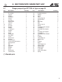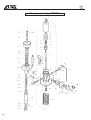
1
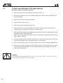
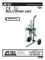
Use and maintenance manual
GB
MULTI SPRAY UNIT
MSU-113 N
ANEST IWATA Europe s.r.l.
46, Corso Vigevano
10155 Torino - Italia
Tel. +39 011-24 80 868
Fax +39 011-85 19 44
www.anest-iwataeu.com
e-mail: [email protected]
ME113NERev.2
Dear Customer,
We thank you for the preference you have given us and we are glad to count you among our customers. We
hope the use of this equipment will satisfy you and your staff.
We have first of all designed our products by focusing not only on our experience, but also on the latest
mechanical innovations. The products have then been manufactured with first-rate materials and techniques
and tested , considering your requirements.
We thank you once again and remember that all our technical services are at your disposal for any present
and future requirement.
Yours faithfully
ANEST IWATA EUROPE
TORINO - ITALY
The company
The mission of ANEST IWATA EUROPE S.r.l. is to supply all their product and spray painting equipment users
and distributors with STATE-OF-THE-ART of technology and with continuous innovation to obtain the best finish at the lowest cost.
Our product range must offer the perfect balance between the use of energy and its effects to help to safeguard the environment.
All the Anest Iwata Europe s.r.l. staff members use their knowledge and competence to provide their customers with high quality, reliability and constant innovation.
Our activities, as the ones of other companies, are in compliance with several European Directives (Safety
and Environment) and International Standards (ISO - Quality and Environment).
As to SAFETY, the standards our products refer to are EC Directive 89/382 and subsequent; all our items of
this type have the CE marking and are supplied with a Technical File, which can be read on request. Moreover
the products are delivered with the proper use manual (according to the EN 292 European regulations) available
in different languages. Furthermore there are the following specific safety standards: EN 1953 for spray guns
and pr EN 12621 for the pressure pump circuits. These regulations can be looked up and purchased at UNI.
As to the QUALITY standards (ISO 9000), ANEST IWATA EUROPE is provided with ISO 9001 certification.
According to our philosophy, we give our partners, distributors and users any possible information necessary
for the use of our products and for the protection of the environment and the safety of the operators.
2
GENERAL CONTENTS
USE OF THE MANUAL...................................................................................................................................4
SYMBOLS USED ...........................................................................................................................................4
INFORMATIVE LETTER................................................................................................................................ 5
WARRANTY ...................................................................................................................................................7
1.
1.1
1.2
1.3
1.4
TRANSPORT AND HANDLING..........................................................................................................8
Transport………………………………………………………………………….........................................8
Transport with cardboard packing……………………………………………….......................................8
Handling………………………………………………………………….....................................................9
Temporary storage……………………………………… .........................................................................9
2.
2.1
2.2
2.3
2.4
2.5
PRODUCT IDENTIFICATION………………………………………………… .......................................10
Plate data………………………………………………………………… .........................................……10
Different models………………………………………………………………………… ............................10
Technical specifications………………………………………………………… ...............................……11
Safety systems………………………………………………………….............................................…...12
Workable products…………………………………………………………… ...................................……13
3.
3.1
OPERATION……………………………………………………………… ...............................................14
Operation description………………………………………………… ....................................................14
4.
4.1
4.2
4.3
4.4
4.5
4.6
INSTALLATION AND START………………………………………… ..................................................15
Check on the purchased product………………………………………………… ..................................15
Conditions for the installation…………………………………………………….....................................15
Installation………………………………………………………………………. .......................................15
Cautions………………………………………………………………………… ........................................16
Drawing of the multi spray unit provided with paint filter…………………………………… .................17
Drawing of the multi spray unit without paint filter…………………………………...............................18
5.
5.1
5.2
5.3
5.4
5.5
5.6
5.7
5.8
USE…………………………………………………………………………...............................................19
Use ....................................................................................................................................................19
Safety rules during use .....................................................………………………………………………19
Clothes…………………………………………………………………… .................................................19
Prewash and adjustment of the upper packing ……………………… ................................................20
Start ……………………………………………………………………… .................................................21
Daily suspensions………………………………………………………… .........................................…..22
Improper and dangerous uses…………………………………………………… ..............................….22
Procedure to discharge the pressure…………………………………….........................................…..23
6.
6.1
6.2
6.3
6.4
6.5
6.6
6.7
6.8
6.9
6.10
6.11
6.12
6.13
6.14
MAINTENANCE AND INSPECTION……………………………………………… .......................…….24
General notes……………………………………………………………………… ...................................24
Safety rules during maintenance………………………………… ........................................................24
Recommended programmed operations…………………………………………..................................24
Procedure to disassemble and reassemble…………………………………….. ..................................25
Disassembly of the motor unit…………………………………………………… ...................................25
Maintenance of the motor unit………………………………………………… .......................................25
Re-assembly of the motor unit………………………………………………. .........................................26
Disassembly of the pneumatic motor from the fluid pump set………………………...........................30
Disassembly of the fluid pump set ....................................................................................................31
Maintenance of the fluid pump set.....................................................................................................32
Re-assembly of the fluid pump set……………………………………………. ......................................32
Re-assembly of the motor to the fluid pump set ………………………………… ................................33
Tests to carry out after the re-assembly……………………………………...........................................33
Maintenance of the paint filter…………………………………………………. ......................................33
7.
MALFUNCTIONS - TROUBLESHOOTING……………………………………………………. ..............34
8.
SECTIONS WITH SPARE PARTS LIST………………………………………… ..................................37
8.1
8.2
8.3
8.4
8.5
8.6
PLUNGER PUMP SET PP7131N……………………………………………………………… ...............37
Paint filter...........................................................................................................................................39
Drain valve.........................................................................................................................................39
Air regulator set .................................................................................................................................40
Suction hose set…………………………………………………………………. .....................................41
Cart set…………………………………………………………………………….. ....................................42
9.
9.1
9.2
DISMANTLING………………………………………………………. .....................................................43
Storage of the equipment………………………………………. ...........................................................43
Dismantling………………………………………………………………..................................................43
3
Use of the
Manual
The use and maintenance manual is the document accompanying the equipment from its manufacture till its dismantling. Therefore, it is an integral part of the equipment.
The manual must be read before starting ANY ACTIVITY involving the equipment including its handling.
Symbols used
The operations which can be dangerous if they are not carried out correctly, are indicated with the
following symbol:
The warnings provided with this symbol refer to the equipment in compliance with “ATEX” 94/9/CE
Directive.
The operations provided with this symbol must be carried out by qualified staff having a specific competence concerning the safety of the areas with an explosive atmosphere.
We recommend following the prescriptions to avoid serious risks for people and environment.
The operations requiring a qualified or specialised staff, to avoid any danger, are indicated with the
following symbol:
We recommend training the staff who have to use the equipment and check if everything is understood and carried out.
Other
symbols
4
Index of the use and maintenance manual
Transport
Description of the equipment
Installation
Ordinary use
Wiring and hydraulic diagrams
Dismantling
Maintenance operations
Informative
letter
This use and maintenance manual is an integral part of the equipment and it must be easily available
to the staff in charge of its use.
The user and the maintenance man must know the content of this manual. None of the descriptions or
pictures contained in this manual are binding.
Although the main features of this equipment are not subject to change, the manufacturing company reserves the right to change those components, details and accessories it deems necessary to
improve the machine or to meet manufacturing or commercial requirements, at any time and
without updating this manual immediately.
COMPLIANCE WITH THE RULES
All the units are planned according to the Essential Safety Requirements of the Machinery Directive
98/37/CE.
Moreover the units are planned and built in compliance with the Essential Safety Requirements (ESR)
of the Enclosure II of Directive “ATEX” 94/9/CE and comply with the following classification:
- Equipment group: II.
- Class: Gas 2G.
- Area: Gas 1
- Maximum surface temperature: temperature class T6.
WARNING
TO ENSURE THE RIGHT OPERATION OF THE EQUIPMENT AND OF THE SAFETY DEVICES,
THE EQUIPMENT MUST BE INSTALLED BY QUALIFIED STAFF:
WARNING
ALL RIGHTS ARE RESERVED, THE REPRODUCTION OF ANY PART OF THIS MANUAL, IN ANY
FORM, IS STRICTLY FORBIDDEN WITHOUT PRIOR WRITTEN AUTHORIZATION OF THE MANUFACTURING COMPANY.
THE CONTENT OF THIS MANUAL CAN BE MODIFIED WITHOUT NOTICE. GREAT CARE HAS
BEEN TAKEN IN COLLECTING AND CHECKING THE DOCUMENTATION CONTAINED IN THIS
MANUAL TO MAKE IT AS COMPLETE AND COMPREHENSIBLE AS POSSIBLE.
5
WARNING
THIS USE AND MAINTENANCE MANUAL DOES NOT MAKE UP FOR ANY DESIGN
INADEQUACY.
In case of breakdown or malfunction, contact the TECHNICAL CUSTOMER CARE
CUSTOMER SERVICE
ANEST IWATA EUROPE s.r.l.
C.so Vigevano, 46 - 10155 Torino
Telefono +39 011.24.80.868
Telefax +39 011.85.19.44
E-mail: [email protected]
WARNING
THE ORIGINAL CONFIGURATION OF THE EQUIPMENT MUST NOT BE CHANGED AT ALL.
On receiving the equipment check that:
The supply corresponds to the order specifications
In case of non-compliance, inform immediately our technical services.
6
Warranty
All ANEST IWATA S.r.I products have a one-year guarantee from the invoice date, unless otherwise
stated in writing. The warranty covers all manufacturing faults and material defects. Any spare part
replacement or repair operations are covered only if they are carried out by our technicians at our
servicing shops.
The faulty parts must be sent CARRIAGE PAID.
Once the components have been repaired, they will be sent CARRIAGE FORWARD to the customer.
The warranty covers no intervention of our technicians during installation or dismantling operations.
If for practical purposes one of our technicians is sent on site, a charge will be made for the time plus
extra for travelling and expenses.
Our warranty does not cover direct or indirect damage to people or property caused by our equipment. It covers no repair operations carried out by the customer or by a third party, either.
THE WARRANTY DOES NOT COVER:
- Damage or breakdown caused by improper use or assembly.
- Damage or breakdown caused by the use of spare parts that are different from the original or
recommended ones.
- Damages or breakdown caused by bad preservation.
- Components subject to wear (described in the spare part list).
WARRANTY FORFEITURE:
- In case of delayed payment or other contractual defaults.
- Whenever changes or repairs are carried out on our equipment without prior written authorisation.
- Whenever the serial number is damaged or removed.
- When the damage is caused by improper use or functioning, or if the equipment falls, is bumped or
by other causes not due to the normal working conditions
- Whenever the unit is disassembled, tampered with or repaired without the authorisation of ANEST
IWATA S.r.I.
All repairs carried out during the warranty period, do not interrupt the warranty duration.
All disputes will be settled in the Court of Justice of Turin.
7
1. TRANSPORT AND HANDLING
1.1
Transport
To transport of the equipment, use only the systems described below. In any case make sure that the
transport and the lifting device can bear the weight of the equipment with its packaging.
WARNING
ALWAYS KEEP THE PACKAGING IN A VERTICAL POSITION.
WARNING
IT IS ADVISABLE THAT THE STAFF IN CHARGE OF HANDLING THE EQUIPMENT WEAR PROTECTIVE GLOVES AND SAFETY SHOES.
WARNING
WHILE LIFTING OR HANDLING THE EQUIPMENT OR ANY OF ITS COMPONENTS CLEAR THE
WORKING AREA. LEAVE ALSO A SUFFICIENT SAFETY AREA AROUND THE EQUIPMENT TO
AVOID DAMAGING PEOPLE OR OBJECTS WHICH COULD BE THERE.
1.2
Transport with cardboard packaging
The equipment is put inside cardboard packaging and wrapped with some shockproof material.
8
1.3
Handling
To handle the cardboard packaging use a trolley. To handle or displace the multi spray unit only use
the cart.
WARNING
FOLLOW THE INSTRUCTIONS ON THE PACKAGING BEFORE HANDLING AND OPENING IT.
HANDLING BY MEANS OF CART
1.4
HANDLING BY MEANS OF TROLLEY
Temporary storage
During transport and storage make sure the temperatures between 0 and 40° C are not exceeded.
In case of storage, make sure the equipment is not put in places where there is excessive humidity.
9
2. PRODUCT IDENTIFICATION
2.1
Plate data
The manufacturer’s identification plate is applied on the multi spray unit (see picture below).
It must not be removed at all, even if the equipment is resold. For any communication with the manufacturer always mention the serial number written on the plate itself.
Model
Max. working pressure
MSU-113N
MANUFACTURED
Year of manufacture
MULTI SPRAY UNIT
MAX AIR W. P.R.
0.68 MPa / 6.8 bar / 98 psi
SERIAL NO.
Serial number
ANEST IWATA EUROPE s.r.l.
C.so Vigevano,46
10155 Torino Italy
CE marking –
Environmental limits (environment temperature between + 5°C and + 40°C).
Maximum surface temperature: temperature class T6
2.2
Models
MSU 113 N:
MULTI SPRAY UNIT MSU 113 N – MODEL WITH PAINT FILTER
Pump type PP 7131N on cart with air regulator, gun spraying adjustment, suction pipe, delivery and
suction paint filter, fluid recirculation.
MSU 113 N:
MULTI SPRAY UNIT MSU 113 N – MODEL WITHOUT PAINT FILTER
Pump type PP 7131N on cart with air regulator, gun spraying adjustment, suction pipe,
suction paint filter, fluid recirculation.
10
2.3
Technical specifications
Model
MSU-113N
MSU-113N
Model
Model with filter
(Figure 1)
Model without filter
(Figure 2)
Dimensions
mm
524x500x1020
524x500x1020
Weight
kg
18 Kg
16.5 Kg
Pump type
Compression ratio
Inlet air pipe fitting
Outlet air pipe fitting
Material inlet pipe fitting
Material outlet pipe fitting
Maximum working pressure
Max fluid pressure
Max. fluid delivery
Max numer of cycle per min
Delivery/cycle
Fluid suction filter
Working temperature
Noise level
Compressor (required power)
FIGURE 1
PP-7131N (Model in stainless steel)
13:1
G1/4”
G1/4”
G1/2”
G1/4”
6.8 bar
88 bar
1.9L/min
110 cycle/min
17.3cc/cycle
50 mesh
5 - 40°C
81.6dB(A)
0.37-1.5Kw
FIGURE 2
11
2.4
Safety systems
Several safety systems have been conceived during the multi spray unit design and manufacture to
safeguard the operator, in compliance with pr EN 12621 Directive about paint.
INFORMATION ABOUT SAFETY
In case of units, which must work in an environment with a potentially explosive atmosphere the staff
in charge, before starting its activities, must disable the unit power supply, by putting it “out of order”
and by taking precautions against any condition, which can cause an accidental restart of the unit.
Moreover, all the other necessary environmental safety measures (for example the possible gas and
residual dust decontamination etc.) must be taken.
SAFETY VALVE
An 8 bar calibrated safety valve is installed to ensure the pump working pressure does not exceed
the limits inside the feeding circuit.
If the calibration pressure is exceeded, the valve opens by releasing the excess of air.
WARNING
DO NOT REMOVE THE PLASTIC VALVE PROTECTION, ANY TAMPERING COULD BE
DANGEROUS FOR THE OPERATOR AND COULD COMPROMISE THE GOOD WORKING OF
THE EQUIPMENT.
BALL VALVE
IN CASE OF ANOMALIES DURING WORKING, TURN THE BALL VALVE LEVER 90°. IN
THIS WAY THE AIR SUPPLY WILL BE INTERRUPTED AND THE RESIDUAL PRESSURE INSIDE
THE PUMP WILL BE RELEASED.
12
Safety
pictograms
Some pictograms showing the safety warnings to be followed by anyone who is going to use it can
be found on the pump.
WARNING
THE MANUFACTURER IS NOT TO BE HELD RESPONSIBLE FOR DAMAGE OR ACCIDENTS TO
PEOPLE OR THINGS DUE TO NON-COMPLIANCE WITH THE PRESCRIBED RULES. THE
OPERATOR IS THE ONLY PERSON RESPONSIBLE.
2.5
Workable products
MULTI SPRAY ANEST IWATA pumps are conceived to paint ferrous material, wood and plastic.
Model MSU 113 N is used for solvent-based paints and water based pains with low or average
viscosity.
To use the equipment with special products ask for the approval of the manufacturer. Moreover, the
technical features of the unit must be adapted for processing such products. ANEST IWATA is not
responsible for any accident due to NON-AUTHORISED and non-qualified personnel using the pump
for purposes that are different from the above-mentioned ones.
WARNING
DO NOT USE:
- ANY HALOGENATED HYDROCARBON SOLVENTS, SUCH AS TRICHLORETHANE, METHYLENE
CHLORIDE OR ANYTHING SIMILAR:
- ANY FLAMMABLE OR VERY TOXIC PRODUCTS SUCH AS PETROL, KEROSENE INFLAMMABLE
SOLVENTS OR COMBUSTIBLE GASES.
- ANY HERBICIDE OR PESTICIDE
- ANY RADIOACTIVE FLUID
13
3. OPERATION
3.1
Operation description
Multi spray pumps are composed of two main parts: the pneumatic motor and the pumping unit; the
pneumatic motor is provided with a pneumatic piston and with a switch for the change of the movement direction.
The pumping unit is made up of an anti-wear chromium plated suction tube and rod. The packing can
be adjusted.
The motor’s straight and alternate movement creates an equivalent movement in the pumping unit.
A system of valves allows the simultaneous suction and pressurization of the product to be sprayed,
in the two chambers of the suction tube, therefore ensuring the utmost uniformity during the application.
FIGURE 1
Cylinder
Pneumatic piston
MOTOR
Rod
Switch
Air inlet
PUMPING UNIT
Upper V packing
Product outlet
Lower V packing
Suction tube
Product inlet
14
4. INSTALLATION AND START
4.1
Check the purchased product
Before using the pump, make sure it has not been damaged during transport or storage.
Also check that all standard components are inside the packaging.
4.2
Conditions for the installation
- The installer must know the ATEX classification of the installation area and also the risks deriving
from a potentially explosive atmosphere, especially explosion and fire, so that he can adopt the suitable protection measures.
- All maintenance operations, assembly and disassembly, must be performed out of the explosion-risk
area and by specialised staff.
- Check that all the accessories comply with the essential safety requirements of the ATEX Directives.
We recommend handling them carefully in order not to modify the features.
- Clean the unit once the installation has been completed.
- To connect the multi spray unit and the gun use the antistatic-type pipeline.
The equipment must be installed by a specialized and authorized staff.
In any case, follow the instructions below.
Painting must preferably take place inside a suitable spray booth equipped with suction device.
Do not use the unit if the suction device is off.
WARNING
IF PAINTING IS CARRIED OUT OUTSIDE THE SPRAY BOOTH, ALWAYS OPERATE IN A PLACE
WITH THE RIGHT VENTILATION TO AVOID THE CONCENTRATION OF INFLAMMABLE VAPOURS
COMING FROM SOLVENTS OR PAINTS.
4.3
Installation
-
[ref. figure 2 page 17 and figure 3 page 18]
Place the equipment on the floor, on a horizontal surface.
Connect the suction hose (A) and the product recirculation hose (B)
Connect the twin pipe for air and paint to compensating filter and air regulator.
Earth the free end of the earthing cable.
Connect the Multi Spray gun to the other end of the air/paint twin pipe
Connect the air supply pipe to the installation.
15
WARNING
- CHECK THE PROPER TIGHTENING OF ALL FITTINGS, SINCE THEIR SUDDEN OPENING
CAN SERIOUSLY INJURE PEOPLE.
WARNING
- CONSULT THE LOCAL CODE FOR DETAILED INSTRUCTIONS CONCERNING THE EARTHING
OF THE WORKING AREA AND THE TYPE OF SYSTEM USED.
- THE EARTH CABLE (INCLUDED IN THE SUPPLY) MUST HAVE A MINIMUM SECTION OF 1.5
MM2.
- ONE END OF THE CABLE MUST BE EARTHED WHILE THE OTHER MUST BE CONNECTED
TO THE COVER OF THE PNEUMATIC MOTOR PACKING.
4.4
Cautions
1. Operate the pump with air filtered by means of an air filter with filtering section smaller than
50 µm; we recommend using a filter with condensate automatic discharge.
2. Do not idle the pump.
3. Do not spray paint or solvents towards the pump.
4. Do not install the pump close to heat sources or exposed to the sun. Locate it in a place sheltered
from water sprinkles.
16
4.5
Multi spray unit with paint filter
FIGURE 2
Pressure regulator G
Stop position
Ball valve (E)
Operating position
Air inlet G 1/4"
Adjusting cup (D)
Upper packing
Recirculation valve (C)
CLOSED
Ground cable
Air outlet G1/4"
Paint filter (F)
Paint outlet G1/4"
Recirculation valve (C)
Suction hose (A)
Recirculation hose (B)
Recirculation valve (C)
OPEN
Paint inlet G 1/2"
17
4.6
Multi spray unit without paint filter
FIGURE 3
Pressure regulator G
Stop position
Ground cable
Ball valve (E)
Operating position
Air inlet G 1/4"
Air outlet G1/4"
Paint outlet G1/4"
Adjusting cup (D)
Upper packing
Recirculation valve (C)
CLOSED
Suction hose (A)
Recirculation hose (B)
Recirculation valve (C)
OPEN
Paint inlet G 1/2"
18
Recirculation valve (C)
5. USE
5.1
Use
This section describes the multi spray unit use in compliance with the safety standards in force. We
recommend reading it carefully.
LIMITS AND CONDITIONS OF USE
Any change of the unit can be carried out only if authorised by ANEST IWATA EUROPE technical
service. If the change is not authorised, the unit is not considered as ATEX approved.
Environmental condition
Environment temperature: min. +5°C; max. +40°C
The plate data concerning the maximum surface temperatures, refer to measurements carried out in
normal environmental conditions and installation.
Even minimum changes of these conditions can have remarkable effects on the heat development.
5.2
Safety rules during use
TO USE the multi spray unit COMPLY WITH the safety precautions and rules described below.
The manufacturing company declines all responsibility if the operator does not comply with them. It is
not to be held responsible for any carelessness during the pump use, either.
If the system is used improperly, it could be broken causing serious damage.
- Use the multi spray unit for professional purposes only.
- Do not change the system; use only Anest Iwata original spare parts.
- Check the system daily: repair or replace immediately all worn or damaged parts.
- Never exceed the maximum working pressure: 6.8 bar (0.68 MPa).
- IT IS FORBIDDEN to use the equipment for purposes that are different from the ones it is
destined to which are described in the use and maintenance manual. If in doubt, apply to
your Anest Iwata reseller.
- Use paints and solvents compatible with the system parts they come into contact with.
- Refer to the paint and solvent features mentioned by the manufacturer.
- Wear the protective clothes described in section 5.3.
- Comply with all the local standards on electric safety and fire risks.
5.3
Clothes
Wear protective gloves and goggles, an oxygen mask and ear protection during operation. Always
follow the laws in force (Ex. ITALIAN LAW 626/94).
19
5.4
Prewash and adjustment of the upper packing.
[Ref. figure 2 page 17 and figure 3 page 18]
1.
Make sure the pump has been properly installed; (see point 4.3)
2.
Immerse the suction hose (A), in the cleaning liquid (clean solvent or water according to the
purchased model).
3.
Place the ball valve (E) in the proper position.
4.
Open the recirculation valve (C).
5.
Loosen the upper packing adjusting cup (D).
6.
Open gradually the air pressure regulator (G) up to the minimum pressure required for the
straight and alternate movement of the pump. (about 0.5 bar).
7.
Adjust the upper packing by tightening gradually the thinner cup (D) until stopping the cleaning
liquid outflow and the pump movement.
NOTE: The failure to observe this point as well as an improper initial adjustment of the packing
might reduce its duration.
8.
Once the packing has been adjusted, increase the air supply pressure (up to about 2 bar) and
let the cleaning liquid flow in the recirculation pipe for a few minutes.
9.
Close the recirculation valve (C) clean the paint pipe and the gun by keeping its trigger pulled.
10. Once you are sure the cleaning has been properly carried out, lift the suction hose from the vessel containing the cleaning liquid and let the residual liquid flow out of the gun first, and then
from the recirculation pipe.
WARNING:
THE PUMP MUST BE CLEANED BEFORE USING IT FOR THE FIRST TIME, IF IT IS NOT USED FOR A
LONG TIME AND AFTER ANY COLOUR CHANGE.
20
5.5
Start [ref. figure
2 page 17 and figure 3 page 18]
Before operation, start the pump by following the operations below:
1. Dip the suction hose (A) in the tank with the product to be pumped.
2. Open the recirculation valve (C) for paint recirculation.
3. Lift and gradually turn the pressure reducer knob (G). Adjust it to a pressure slightly higher than
2.0 bar, to enable the pump to release the air.
4. Close the two-way valve for paint recirculation (C) and release the air through the gun, as well.
5. Increase the pressure of the reducer connected to the pump, according to the desired working
pressure.
CAUTIONS
a) Use multi spray gun only.
b) When the paint level inside the tank decreases, the pump might suck some air. Increase the
level of paint.
c) Do not drag the pump by pulling it by the pipes.
d) Do not spray towards the eyes or towards other people
CAUTIONS: EMERGENCY STOP
WHEN THE PUMP MUST BE STOPPED BECAUSE OF ONE OF THE FOLLOWING REASONS:
a) The material never stops coming out of the gun
b) Fluid discharge through the connectors or the damaged pipe
- Close the BALL VALVE (E) (stop position)
WARNING
a)
b)
c)
d)
e)
When assembling or removing the gun nozzle, always block the trigger safety catch.
Never remove the gun trigger safety catch
Never exceed the maximum working pressure (6.8 bar).
Always use a multi spray ANEST IWATA gun, which is provided with various safety devices.
During operation, never touch the moving parts. Before carrying out any maintenance operation, disconnect the air supply and discharge the residual pressure.
21
5.6
Daily interruptions
[ref. figure 2 page 17 and figure 3 page 18]
1. Upon interrupting the use of the pump:
- It is not necessary to disconnect the air supply, if the interruption is short.
- If the interruption period is long, turn the ball valve (E), discharge the air from the circuit and open
the recirculation valve (C) to release the residual fluid pressure.
2. When the pump is stopped at the end of the working day:
- Clean the fluid ducts.
- Remove the suction hose filter, the filter inside the compensating device (in the multi spray unit with filter), the gun filter and clean them.
5.7
Improper and dangerous uses
A wrong earthing, an insufficient ventilation, a naked flame or a spark can cause a fire or an
explosion and provoke some serious injuries.
WARNING
IF SPARKS OR AN ELECTRIC DISCHARGE ARE PERCEIVED, INTERRUPT IMMEDIATELY ALL
PAINTING OPERATIONS.
DO NOT USE THE SYSTEM UNTIL THE CAUSE OF THE PROBLEM IS IDENTIFIED.
Keep away from the working area all kinds of waste, solvent containers, solvent or petrol
soaked rags or clothes.
Before starting the system disconnect all the electrical connections inside the working area.
Before using the system switch off all the naked flames and pilot lights inside the working area.
Do not smoke inside the working area.
During painting operations, or if there are some vapours in the air, do not switch on or off the lights
inside the working area.
Do not use any petrol engine inside the working area.
Some organic solvents or discharged toxic vapours can enter the eyes or the skin, be swallowed
or inhaled, provoking serious injuries.
When the air engine is running, keep the face away from the exhaust.
22
5.8
Pressure release process
WARNING
1. Close the air supply to the pump by turning the pressure reducer adjustment anticlockwise down
to 0 bar.
2. Enable the safety catch of the multi spray gun trigger.
3. Make sure the recirculation pipe is not clogged, then gradually open the recirculation ball valve
and leave it open.
4. Hold the gun tightly and lean it against the metal vessel with the paint. Remove the safety catch of
the multi spray gun trigger and gently pull the trigger to release the pressure inside the multi spray
pipe and inside the gun.
5. Block the multi spray gun trigger once more by means of the safety catch.
6. If you believe the pressure has not been fully released by following the instructions provided in
point 4, loosen the gun nozzle carrier to gradually release the residual pressure, then loosen it
completely. Clean the fluid passage ducts.
23
6. MAINTENANCE AND INSPECTION
6.1
General notes
- Observe the intervals of inspection and ordinary maintenance to ensure suitable working conditions and explosive-proof protection.
- Before repairing or maintaining the internal parts, wait for the complete cooling of the unit, to prevent you from coming into contact with hot parts thus avoiding any burns.
- After maintenance, make sure that all the safety measures are restored.
- At the end of maintenance/repair clean the unit.
- For the repair, use only original spare parts.
A suitable maintenance is important for a longer duration of the equipment in good working conditions and efficiency ensuring functional safety as time goes by.
All maintenance operations must be carried out by qualified staff. The pump design and the materials used to manufacture it limit the maintenance interventions to a simple periodic cleaning
The staff must be provided with the individual protections that are generally used for similar operations. They also must follow the safety rules described in section 6.2.
6.2
Safety rules during maintenance
The main rules to follow during maintenance interventions on the unit are:
1. Disconnect the pneumatic supply before replacing any component.
2. Do not wear rings, watches, chains, bracelets, etc. during maintenance operations.
3. Always use the individual protections (gloves, safety shoes, etc.).
4. Do not use naked flames, points or pins for cleaning.
5. Do not smoke.
24
6.3
Recommended scheduled operations
Daily
maintenance
A. Clean the nozzle, the gun paint filter and the compensating filter (multi spray unit with filter) with
a cleaning solvent.
B. Clean all parts in contact with paint.
C. Check the good operation of the safety devices.
Every 50
working hours
A. Clean the internal parts of the paint ducts with cleaning solvents, especially if highly pigmented
paints or paints with many particles tending to deposit are used.
B. Clean the paint inlet filter.
Every 100
working hours
A. Clean the internal parts of the paint ducts with cleaning solvents, using a product able to remove
all traces of deposited paint.
Every 300
working hours
A. Inspect and tighten the V packing of the pump motor.
Every 500
working hours
A. Grease all motor and air cylinder sliding parts.
Every 1000
working hours
A. Disassemble all components and clean them.
B. Replace all worn components.
6.4
Disassembly and re-assembly procedure
WARNING
Before starting any maintenance operation, remove the air supply pipe and make sure the inner residual pressure has been released.
6.5
Motor group disassembly
1. Loosen the four bolts (26) and the air hose (11) then
remove the seat block (A) from the main body
2. Loosen the cap (36) and remove:
- spring (35);
- interlock end piece (33);
- washer (34);
- interlock piece (32)
3. Loosen and remove the air cylinder (1)
4. Remove the split pin (28)
5. Remove the adaptor (23), unscrew the stopper (15)
and remove the spindle set (B) from the main body
(27)
6. Loosen the cap nut (2) and remove:
- washer (3); [quanity 2]
- packing (4)
- washer (not visible in the drawing)
7. Remove the stopper (15) from the spindle set (7)
6.6
Motor group maintenance
Any time the motor is disassembled, we recommend replacing the following components
-
Packing
(RIF. PAGE 27 COMPONENT 4)
Y Packing (RIF. PAGE 27 and page 28 COMPONENT 14)
Moreover, check the wear condition of all other components, and if necessary replace them.
25
6.7
Motor group re-assembly
WARNING
Remove the air feeding pipes and make sure the residual internal pressure has been released before
starting any maintenance operation
IMPORTANT
1. Put grease on all the moving components, o-rings and packing located inside the air cylinder.
2. Make sure the interlock piece is inserted in the rod chink
3. Make sure the block is located at the top when the piston reaches the upper end of stroke and at
the bottom when the piston reaches the lower end of stroke.
Seat block
Interlock piece
Rod
26
1. Put the stopper (15) on the spindle set (7)
NOTE: the following components are assembled on the
stopper
- stopper (12)
-
washer (13)
-
Y packing (14)
-
O-ring (6)
2. Assemble the following components on the spindle
set (7)
-
washer (5)
-
washer (3) [quantity 2]
-
packing (4)
then tighten the cap nut (2)
27
3. Insert the spindle set (7) in the main body (27)
4. Screw the stopper (15) in the main body (27)
5. Screw the adaptor (29) and the spindle set (7);
6. Insert the split pin (28);
7. Screw the air cylinder (1) ;
28
8. Lubricate with grease and then insert the following
components in the cap (36):
-
spring (35)
-
interlock end piece (33)
-
interlock piece (32)
9. Insert the washer (34) in the main body
10. Screw the cap (36) to the main body
11. Insert the seat block (A) in the main body and
screw the four bolts (26)
12. Assemble the elbow union (21) and the special
joint (8) .
13. Assemble the air hose (11)
29
14. Position the packing (22)
15. By using the cross pan-head setscrew (24)
screw the exhaust cover (23) to the main body.
[The ground cable (60) is anchored to the
exhaust cover by means of the cross pan-head
setscrew (24) ]
6.8
Pneumatic motor disassembly from the fluid pump set
1. Keep the rod (41) still and unscrew the joint (29)
2. Loosen and unscrew the three nuts (39)
30
6.9
Fluid pump set disassembly
1. Secure the suction main body (40), unscrew the suction tube (54) and slip it out.
2. Slip the rod (41) out of the suction main body (40) .
3. Loosen the adjustment nut (47) and remove the
upper valve holder set (53).
4. Remove the V packing male adaptor (48), the lower
V packing (49), the lower V packing female adaptor
(50) and the ball (51)
5. Unscrew the thinner cup set (42) from the suction
body (40) and remove the sleeve (43), the upper
V packing female adaptor (44), the upper V packing
(45) and the upper V packing male adaptor (46).
6. Unscrew the valve adaptor set (58) from the suction
tube (54) and remove the ball (57).
31
6.10
Fluid pump set maintenance [ref. figure on page 31]
1. Dip all components in the cleaning liquid and clean them carefully
2. Make sure the rod (41) and the suction tube (54) are not damaged. If they show deep scratches in the
sliding area, replace them.
3. Check that the valve holder set (53) and the valve adaptor set (58) are not damaged, especially in the
area in touch with the ball. If any anomaly is found, replace them.
4. Whenever the pumping unit is completely disassembled, it is advisable to replace the following components.
-
UPPER V PACKING SET
LOWER V PACKING SET
BALL
BALL
(45)
(49)
(51)
(57)
Moreover, check the wear conditions of all the other components and replace them, if necessary.
6.11
Fluid pump set re-assembly
Reverse the above mentioned procedure bearing in mind the following points:
1. Adjust the lower packing in order to obtain a “smooth sliding movement of the suction tube”.
NOTES:
a) use of new V packing : to obtain the maximum efficiency of the multi spray unit, we recommend
adjusting the V packing to obtain a distance of 0.2 –0.3 mm between the adjusting nut and the
lower female adaptor; [ref. figure a].
b) use of partially worn V packing : the V packing might be worn in the area which comes in contact
with the suction tube or with the rod; it is therefore difficult to establish the best condition for the
adjustment; (the higher is the packing wear, the lower must be the distance between the adjusting nut and the lower female adaptor).
Figure A
Female adaptor
Adjusting nut
32
c) If the packing is too tight their duration shall result extremely reduced.
d) A constant and suitable adjustment together with a correct maintenance allows a high packing
duration.
2. Do not use grease to lubricate the sliding parts of the pump rod, since it might compromise the following
painting operations.
6.12
Motor group re-assembly to the fluid pump set [ref. figure on page 31]
1. In order to align the two parts (pneumatic motor and pump rod) in the best position, it is advisable to
tighten the three nuts (39) and the suction tube (54), with the running pump. (Air pressure 0.5 bar).
This procedure allows a further reduction of the adjustable packing wear.
6.13
Tests to be carried out after the re-assembly
1. The pump must start with a supply pressure equal to at least 1.5 bar.
2. Check the possible air and paint spillage. If necessary, tighten the relevant components.
6.14
Paint filter maintenance
If the pump is properly used (a thorough cleaning is carried out each time it is used) the paint filter does not
require special maintenance operations; besides those related to the cleaning and replacement of the filter
itself.
If there is some solidified paint inside the filter or inside the paint ducts, disassemble it completely, clean it
carefully and re-assemble it.
33
7. TROUBLE SHOOTING
Problem
1. The air pressure
does not increase.
2. The paint does not
flow out of the gun
Cause
Check
Solution
a) The ball valve is not in the
correct position.
a) Make sure the ball valve is in the
proper position
a) Adjust the ball valve in
the proper position
b) The air regulator is not open.
b) Check the proper operation of the
regulator
b) If it is closed, open it.
If it is damaged, replace it.
c) Insufficient air pressure.
c) Check that the indicator of the
pressure gauge works correctly
c) If the compressor does not
supply enough air pressure,
replace it with one of greater
capacity
a) Clogged paint filter or paint
circuit
a) By opening the recirculation valve the
paint does not flow out
a) The paint circuit is obstructed
from the pump inlet to the fluid
pipe fitting. Check the paint
circuit and remove the material
obstructing the passage.
b) By opening the recirculation valve the b) The paint course, from the gun
paint flows out regularly, but not when
nozzle to the fluid pipe fitting,
pulling the gun trigger.
is blocked. Check for the
obstructed point and remove
the clogging; this problem is
usually caused by the obstruction of the gun filter.
c) Clogged nozzle
c) Remove the nozzle and pull the trigger c) If the paint flows out it means
of the gun
that the nozzle is clogged. Free
the nozzle with a steel pin and
clean it with a non-metallic
brush soaked in the suitable
solvent.
d) Safety stop jammed
3. The pump does not
work
d) Unlock the safety valve
a) The air does not supply the
pneumatic motor
a) Check the air supply pipe
a) Replace it if damaged or clogged
b) The equipment has a technical
problem
b) Separate the pneumatic motor from the b) If the motor is running properly
pumping group and test it by using a
follow the instructions provided
different pipe
in the solution column point
2 (a-b)
c) If the motor is not running properly, disassemble the cylinder
and inspect it. In case of particular anomalies, send it to our
Customer Care Technical
Service.
4. The pump does
not stop
34
a) Some air got inside the
paint ducts
a) Make sure the suction hose is
properly connected
a)Tighten the suction hose fitting
b) Some air remains inside
the paint ducts
b) Make sure the paint is in good
condition and that the dip tube
suction filter set is fully dipped
in the product to be pumped.
b) If the paint is in standard
condition increase its level
at least until it fully covers the
dip tube filter set.Then, carry
out the start-up operations
relative to the release of
air from the paint ducts.
Problem
Cause
Check
Solution
c) Damaged or dirty valves (upper
or lower).
c) Disassemble both and inspect both
the seat and the ball
c) Clean them if they are
encrusted with solidified paint
residues.Otherwise, if they
are damaged replace them.
d) The lower V packing (inside the
suction tube) is not tight.
d) Disassemble the suction tube and
check the wear.
d) If it is enough, adjust them.
Otherwise, if they are
irreparably worn out, replace
them
e) Leakage from the paint ducts
e) Inspect all the paint ducts
e) If any leakage is found,
eliminate.
f) The recirculation valve is not
closed
5. The spray-fan size
keeps changing
6. The air pressure
gauge indicates the
presence of air
even though the air
regulator is closed
7. Presence of air
bubbles in the paint
a) Worn out V packing
f) Close the recirculation valve
a) The pump does not stop
a) If it is enough, adjust them.
Otherwise, replace them if
they are worn out.
b) Damaged or dirty valves or balls. b) The pump does not stop
b) Disassemble and clean them.
Replace them if they are too
damaged
c) Worn out gun nozzle
c) Replace it
d) The paint filters are dirty
d) Clean or replace them
e) Clogged air or paint ducts
e) Clean them
f) Presence of air bubbles in the
fluid
f) Repeat the same starting
procedure
a) The air regulator is
damaged
a) Replace it
a) Wrong starting procedure
a) Repeat the starting procedure
b) The suction hose or the lower
valve body are loosened
b) Tighten them
c) The lower V packing (between
the suction tube and the lower
valve) is worn out
c) Replace it
8. Paint leakage from the a) Loosened thinner cup set
thinner cup set
b) Worn out or damaged upper
V packing
a) Tighten gradually,
checking the leakage
b) Replace them
35
Problem
9. Paint leakage between the
main body and the suction
tube
36
Cause
Check
Solution
a) Loosened suction tube
a) Tighten
b) The upper V packing (between the main body
and the suction tube) is worn out or damaged
b) Replace it
10. Paint leakage from the paint
filter (model with paint filter)
a) Loosened cylinder
a) Tighten it
11. Air leakage from the air
motor
a) Worn out or damaged O-rings (ref. Page 38
components 16-20)
a) Replace them
b) Worn out or damaged washer (ref. page 38
component 34)
b) Replace it
c) Worn out block (ref. page 38 component 17)
c) Replace it
d) Damaged sleeve (ref. page 38 component 10)
d) Replace it
e) Loosened nut (ref. page 38 component 9)
e) Tighten or replace it, if
damaged
8. SECTIONS WITH SPARE PART LIST
8.1
Plunger pump set type PP7131N ref. figure on page 38
Pos.
Description
1
2
3
4
5
6
7
8
9
10
11
12
13
14
15
16
17
18
19
20
21
22
23
24
25
26
27
28
29
30
31
32
Air cylinder
Cap nut
Washer
Packing (*)
Washer
O- ring
Spindle set
Special joint
Joint nut
Sleeve
Air hose
Stopper
Washer
Y Packing (*)
Stopper
O-ring
Block
Guide plate
Seat block
O-ring
Elbow union
Packing
Exhaust cover
Cross pan-head setscrew
Spring washer
Bolt
Main body
Split pin
Adaptor
Screw
Block carrier
Interlock piece
Quantity
Pos.
1
1
2
1
1
1
1
1
1
1
1
2
2
2
1
1
1
1
1
2
1
1
1
1
1
4
1
1
1
2
1
2
33
34
35
36
37
38
39
40
41
42
43
44
45
46
47
48
49
50
51
52
53
54
55
56
57
58
59
60
61
62
63
64
Description
Interlock end piece
Washer
Spring
Cap
Connecting rod
Spring washer
Nut
Main body
Rod
Thinner cup set
Sleeve
V packing female adaptor
V packing (*)
V packing male adaptor
Nut
V packing male adaptor
V packing (*)
V packing female adaptor
Ball (*)
Packing
Valve holder set
Suction tube
Pin
Packing
Ball (*)
Valve adaptor set
Special nipple
Ground cable
Safety valve
T joint FMF
Quick swivel elbow
Spring
Quantity
2
2
2
2
3
3
3
1
1
1
1
1
4
1
1
1
4
1
1
1
1
1
1
1
1
1
1
1
1
1
1
1
(*) Wearable parts
37
Plunger pump set type PP7131N
38
8.2
8.3
PAINT FILTER SET
For MSU 113 N : model with filter
A
Pos.
Description
Quantity
A
Paint filter set
1
1
Plug
1
2
Cylinder
1
3
Filter plug
1
4
Filter bolt
1
5
100 mesh filter
1
6
Packing
1
7
Nut
1
8
Packing
1
9
Union joint R3/8”-G3/8”
1
10
Pin
1
11
Filter adaptor
1
12
Elbow Rp3/8” FF
1
13
Joint R3/8”-G1/4”
1
14
Elbow R1/4”MM
1
15
Two-way valve G1/4”FF
1
16
Hose joint R1/4” M8x6
1
17
Body
1
DRAIN VALVE SET
For MSU 113 N: model without paint filter
Pos.
Descrizione
A
Drain valve set
1
1
Elbow MM R3/8”-G1/4”
1
2
T Joint Rp 3/8”FFF
1
3
Nipple R3/8”M – R1/4”M
1
4
Two-way ball valve G1/4” FF
1
5
Hose joint R1/4”M M8x6
1
6
Union joint R3/8”M-G3/8”F
1
A
Quantity
39
8.4
AIR REGULATOR SET
For MSU 113 N : model with filter
For MSU 113 N : model without filter
Pos.
Description
A
Air regulator set
1
1
Quick joint B.P. 1/4”M 90°
1
2
Ball ball valve with hexaust hole
1
3
Nipple G1/4” MM
1
4
Air regulator G1/4” FF
1
5
T Joint MFM G1/4”
1
6
Nipple Rc1/4”M – G1/4”F
2
7
Air regulator with filter G1/4”FF
1
8
Elbow joint MF R1/4”M-G1/4”F
1
9
Pressure gauge (optional)
2
10
Hexagonal socket bolt (optional)
2
11
Hexagon nut (optional)
2
A
40
Quantity
8.5
STAINLESS STEEL SUCTION HOSE SET
For MSU 113 N : model with filter
For MSU 113 N : model without paint filter
Pos.
Description
Quantity
A
Suction hose set
1
1
Suction hose
1
2
Air hose
1
3
Filter set 15x1 for 1/2 ” suction hose
1
3-1
Suction cup M 15x1
1
3-2
Suction cup filter 50 MESH ( 100 MESH filter as option)
1
3-3
Filter stopper
1
A
41
8.6
CART SET AND PLATE
FOR MSU 113 N : MODEL WITH PAINT FILTER
FOR MSU 113 N : MODEL WITHOUT PAINT FILTER
Pos.
42
Description
Quantity
1
Frame set
1
2
Wheel
2
3
Split pin
4
4
Washer
4
5
U-bolt 1/2
2
6
Pump base
1
7
U -bolt 3/4
2
8
Shaft
1
9. DISMANTLING
9.1
Equipment storage
If the multi spray unit is to be stored for a certain period, the following operations are recommended:
Disconnect the equipment from the energy sources.
Remove all residues and deposits from the pump.
Cover the equipment with a waterproof tarpaulin.
9.2
Dismantling
If for any reason the pump is to be dismantled, some important rules have to be followed to safeguard
the environment.
All sheaths, flexible ducts and plastic or non metal components will have to be disposed of separately.
43
ANEST IWATA Europe S.r.l.
46, Corso Vigevano 10155, Torino Italy
Direct Tel. +39 011 - 24 80 868
Fax +39 011 - 22 74 406
[email protected]
www.anest-iwataeu.com
European Sales Branches:
ANEST IWATA Italia S.r.l.
46, Corso Vigevano 10155, Torino (Italy)
Tel. diretto +39 011 - 24 80 868 - Fax +39 011 - 85 19 44
[email protected]
www.anest-iwata.it
ANEST IWATA Scandinavia AB.
Ögärdesvägen 6C, 433 30 PARTILLE
Tel. +46 (0)31 - 340 28 60 - Fax +46 (0)31 - 340 28 69
[email protected]
www.anest-iwata.se
ANEST IWATA Europe S.r.l.
SUCURSAL ESPAÑA Y PORTUGAL
Avda.del Maresme, 44-46 Planta 2 OF. 25 / 08918 - Badalona (Barcelona)
Tel.:+34 933 20 59 93 - Fax.:+34 933 20 55 64 - [email protected]
ANEST IWATA France S.A.
25 rue de Madrid - BP 7405 38074 St Quentin Fallavier
Tél. +33 (0)4 - 74 94 59 69 - Fax +33 (0)4 - 74 94 34 39
[email protected]
www.anest-iwata.fr
ANEST IWATA Europe S.r.l.
NIEDERLASSUNG DEUTSCHLAND
Dorfäckerstr. 25, 74248 Ellhofen
Telefon: +49 (0)7134- 917368 - Fax: +49 (0)7134 - 917378
Handy: +49 (0)172 - 62 74 542
[email protected]
www.anest-iwata.de
ANEST IWATA U.K. Ltd.
Unit 10 Little End Road - Eaton Socon
St. Neots - CAMBRIDGESHIRE
PE19 8JH
Tel.: +44 (0) 1480 405419 Fax: +44 (0) 1480 217610
[email protected]
www.anest-iwata.co.uk