1
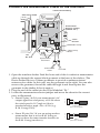
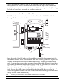
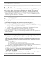
UNIVERSAL ANEMOMETER INTERFACE I N S TA L LA TI O N M A N U A L With this interface, some anemometers not manufactured by Davis Instruments can be used with the Vantage Pro2. Non‐Davis anemometers must have AC voltage output signals. The frequency of the AC signal must be linearly propor‐ tional to the wind speed. This interface has been tested with R. M. Young anemometers, model number 05103; and with NRG anemometers, model 1900 NRG#40C or MAX40. How‐ ever, the interface is not limited to those products. Components The Universal Anemometer Interface includes the following components and mounting hardware: Interface Shelter 3-Volt Lithium Battery 1/4" x 1-1/2" Lag Screws U-Bolts #6 x 1/2" (3.5 x 12 mm) Self-Threading Screw #6 Washer Cable Clamp 1/4" Flat Washers 1/4" Lock Washers 1/4" Hex Nuts 8" Cable Ties Anemometer Cable (6-Conductor Cable) ISS Cable (4-Conductor Cable) 1 Tools for Setup In addition, you will need some or all of the following materials: • • • • Adjustable wrench or 7/16ʺ wrench Compass or local area map (to adjust wind direction, if needed) Drill and 3/16ʺ (5 mm) drill bit (if mounting on a vertical surface) Carpenter’s level (if mounting on a vertical surface) If you are installing a Davis Integrated Sensor Suite (ISS) or Anemometer Transmitter Kit and the non-Davis anemometer at the same time: Install your ISS first, following the instructions in the installation manual. How‐ ever, skip the steps that direct you to connect the anemometer cable to the SIM. When you are ready to mount the anemometer (for the ISS, after you have mounted the rain collector side of the ISS), follow the instructions in this manual starting with “Mount the New Anemometer” on page 4. Installation Steps The following is an outline of the steps necessary to install an anemometer with the Universal Anemometer Interface. These steps are used as section headings in this manual and are explained in greater detail in the appropriate section. • Remove the old anemometer from its current location and disconnect the anemometer from the ISS transmitter (if necessary) • Mount the new anemometer • Mount the interface shelter • Connect the anemometer cable to the anemometer • Insert the battery in the interface shelter • Connect the anemometer cable to the interface • Connect the ISS cable to the interface • Connect the ISS cable to the ISS or Anemometer Transmitter Kit SIM • Configure the console 2 If you are replacing an already mounted and installed anemometer: Remove the old anemometer from its current location The following two steps assume that your ISS, with standard anemometer, is already mounted. Disconnect the old anemometer from the ISS transmitter Open the Vantage Pro2 SIM Box and unplug the anemometer cable from the receptacle labeled WIND on the SIM. Remove the foam insert and then guide the cable out of the box. When finished, make sure to replace the foam insert ensuring that the access port is filled and free of any voids. If you are discon‐ necting an anemometer transmitter kit, guide the anemometer cable through and free it from the grommet. If your ISS and anemometer are mounted as a single unit (both together on a pole) Unfasten the anemometer: 1. Remove the black rain collector cone from its base by rotating cone counter‐clockwise until its latches line up with openings in the base and you can lift it off. It is much easier to reach the hex nuts with a wrench if you remove the rain collector cone first. 2. Using an adjustable wrench or 7/16ʺ wrench, remove the hex nuts and wash‐ ers holding the anemometer’s plastic mounting base on the pole. Set the ane‐ mometer down for a moment. 3. Remove the hex nuts and washers holding the rain collector side on the pole. Retrieve the U‐bolt that was holding the anemometer. 4. Using the washers and hex nuts, fasten the rain collector side back onto the pole. Flat washer goes on first, then lock washer, then hex nut. 5. Put the rain collector cone back on. Rotate the cone clockwise until the latches slide into place. If your old anemometer is mounted by itself Unfasten it by using an adjustable wrench or 7/16ʺ wrench to remove the hex nuts or lag screws. 3 Mount the New Anemometer Refer to the manufacturer’s directions to mount the new anemometer. However, keep the following factors in mind as you choose a location for your anemometer and the interface shelter: • Mount the anemometer at least 4ʹ (1.2 m) above the roofline for accurate wind readings. • Mount the interface shelter nearby, with the solar panel facing the sun. In the Northern Hemisphere, position the transmitter shelter with solar panel facing south for maximum sun exposure. (In the Southern Hemisphere, position the shelter with solar panel facing north.) Mount the Interface Shelter Mounting on a pole 1. While holding the shelter against the pole, place a U‐bolt Hex Lock around the pole and Flat Washer Nut Washer through the two holes on at the top of the shelter. U-Bolt 2. Place a flat washer, a lock washer and a hex nut on each of the bolt ends. 3. Using an adjustable wrench or 7/16ʺ wrench, tighten the nuts. 4. Place the second U‐bolt around the pole and through the two holes at the bot‐ tom of the shelter. Put a flat washer, a lock washer, and a hex nut on each bolt end, and tighten the hex nuts. Note: 4 Remember to position the shelter so the solar panel has maximum exposure to the sun. Mounting on a vertical surface 1. With a 3/16ʺ (5 mm) drill bit, drill two holes approximately 2ʺ (50 mm) apart. Use a carpenter’s level to ensure the holes are level. 2. Drill two more holes 7‐1/32ʺ (17.9 cm) below the upper Lag Screw Flat holes. Washer 3. Insert the 1/4ʺ x 1‐1/2ʺ lag screws through the flat washers, and through the holes at the top of the shelter into the post. Using an adjustable wrench or 7/16ʺ wrench, tighten the lag screws. 4. Insert the 1/4ʺ x 1‐1/2ʺ lag screws through the flat washers, and through the holes at the bottom of the shelter into the post. Using an adjustable wrench or 7/16ʺ wrench, tighten the lag screws. Note: Remember to position the shelter so the solar panel has maximum exposure to the sun. 5 Insert the Battery 1. Insert the 3‐volt lithium battery into the battery holder, matching the “+” sign on the battery with the “+” sign inside the interface shelter. Note: It will take approximately one minute for the capacitor to charge and the unit to begin functioning. Connect the Cable to the New Anemometer R. M. Young 05103: 1. Open the junction box on the anemometer and cut the jumper wire. (Its location is marked “JUMP FOR COMMON REF”.) 2. Unscrew the sealing nut on the strain relief. 3. One end of the 6‐connector cable has five colored wires, tinned and stripped, and a white (unused) wire. Feed this end of the cable through the sealing nut and the strain relief into the junction box. 4. Connect the wires to the numbered terminal strip as follows: Black . Red . . . Green . Yellow Blue . . White . . . . . . . . . . . . . . . . . . . . . . . . . . . . . . . . 2 . 3 .4 . 5 .6 . unused 5. Replace the junction box cover and sealing nut. NRG#40C/MAX40: 1. Use only the black and blue wires. Connect the black wire to the anemometer’s black ground wire and the blue wire to the anemometer’s white signal wire. 2. Connect the red and green wires together. 6 Connect the Anemometer Cable to the Interface 3-Volt Lithium Battery Solar Panel Cable Anemometer Selector Jumper (labeled “P2”) “OUT” RJ Jack P2 3 2 1 IN OUT Cable Clamp Cable Clamp Mount “IN” RJ Jack Square Black Grommets Anemometer Cable ISS Cable 1. Open the interface shelter. Feed the loose end of the 6‐conductor anemometer cable up through the square black grommet at the base of the shelter. (The Davis shelter has two of these grommets to provide weather‐resistant entrances for cables. In this case, use the grommet on the right. You can also remove the grommet, thread the cable through it and then replace the grommet in the shelter if that is easier.) 2. Plug the end of the cable into the RJ jack labeled “IN.” 3. Locate the anemometer selector jumper and move the shunt to the correct pins, as illustrated • Shunt P2 pins 1 & 2 if your anemometer’s AC output signal has a frequency of 90 Hz when the wind speed is 19.7 mph or 8.8 m/s; transfer function: mph = Hz x 0.219. (e.g. R. M. Young 05103). • Shunt P2 pins 2 & 3 if you are using another anemometer that is not an R.M. Young or does not have the same transfer function as the R.M. Young (see above). 3 2 1 R.M. Young (Pins 1 & 2 shunted) 3 2 1 Other (Pins 2 & 3 shunted) 7 Connect the ISS Cable to the Interface 1. Feed one end of the 4‐conductor ISS cable into the same grommet as the 6‐ conductor cable. 2. Plug it into the RJ jack labeled “OUT.” 3. Secure both cables inside with the cable clamp. Place the cable clamp over both cables between the grommet and the receptacle. Secure the cable clamp to the shelter by threading the provided #6 screw through the washer and cable clamp and then screwing it into the cable clamp mount inside the hous‐ ing. (See illustration on page 7.) 4. Close the shelter, being careful not to pinch the solar panel cable. Connect the ISS cable to the SIM For a Vantage Pro2 ISS This illustration shows the Sensor Interface Module, or “SIM”, inside the Vantage Pro2 transmitter shelter. Sensor Interface Module (SIM) Foam Insert ISS Cable 1. Open the Vantage Pro2 transmitter shelter. 2. Pull the foam insert out of the cable access port in between the cables and set the foam aside. 3. Insert the ISS cable through the cable access port with the connector lever down. 4. Firmly insert the end of the ISS cable into the connector labeled WIND. The lever clicks into place. 8 5. Make sure that the cables lie flat on the bottom of the cable access port. 6. Firmly insert the foam in between the cables and the top of the cable access port, taking care to ensure that the foam seals the access port entirely, leaving no holes or gaps large enough for weather or insects. Note: Refer to your Vantage Pro2 ISS Installation Manual for more information. For an Anemometer Transmitter Kit 1. This illustration shows the Sensor Interface Module, or “SIM”, inside the Vantage Pro2 transmitter shelter. SENSOR INTERFACE MODULE UV SUN RAIN WIND TEMP HUM Cable Clamp Cable Clamp Mount Square Black Grommets ISS Cable 1. Push the end of the ISS cable up through the square black grommet into the transmitter shelter. Every Davis shelter has two of these grommets to provide weather‐resistant entrances for cables. In this case, use the grommet on the right. You can also remove the grommet, thread the cable through it and then replace the grommet in the shelter if that is easier for you. Plug the end of the ISS cable into the receptacle labeled WIND on the SIM. 2. Place the cable clamp over the ISS cable between the grommet and the recep‐ tacle. Secure the cable clamp to the shelter by threading the provided #6 screw through the washer and cable clamp and then screwing it into the cable clamp mount inside the housing. Note: Refer to your Anemometer Transmitter Kit Manual for more information. 9 Configure the Console Note: If your are not using an R.M. Young anemometer, you must use a Vantage Vue console. This console allows for the special calibration needed. Vantage Pro2 Console If your anemometer required that P2 pins 1 & 2 be shunted (e.g. R.M. Young, see page 7) follow these instructions to configure your Vantage Pro2 console: 1. Enter Setup Mode by pressing DONE and the “‐” key at the same time. 2. Press and release the DONE key to scroll through the setup screens until WIND CUP SIZE appears. Press the “+” and “‐” keys to scroll through the wind cup options and select “OTHER.” Note: Early firmware versions may not have the OTHER option. You can update your firmware at www.davisnet.com/support. 3. Press and hold DONE to return to the current weather screen. Vantage Vue Console 1. Enter Setup by pressing and releasing 2ND and then SETUP. 2. Press and release DONE until Screen 6: Transmitter IDs appears. • If your console is receiving from a Vantage Pro2 ISS, press GRAPH to change the type of station assigned to “VP2 ISS.” • If your console is receiving from an Anemometer Transmitter Kit, press GRAPH to change the type of station assigned to “WIND.” 3. Press and release DONE to scroll to Screen 12: Wind Cup Type. 4. Press the “+” and “‐” keys to scroll through the three wind cup options and select “OTHER.” Note: If you are using an R.M. Young anemometer skip to Step 6. 5. If your anemometer required that P2 pins 2 & 3 be shunted (e.g. not an R.M. Young), you must calibrate the Vantage Vue console. Follow these additional steps to determine the calibration number and calibrate the console: a. Review your anemometer’s literature or technical specifications to deter‐ mine its transfer function The transfer function should be in the following format: V = (F x M) + B V = Velocity in m/s (meters per second) F = Frequency in Hz (hertz) or PPS (pulses per second) M and B = Constants (defined in the anemometer’s transfer function) b. Calculate your calibration number: Cal. No. = 1000 x M Example: The NRG40C/Max 40 anemometer has a transfer function of V = (F x 0.756) + 0.35. Therefore the calibration number is 1000 x 0.756, or 0756. c. On the console, press 2ND and GRAPH to display “WIND CAL NUMBER”. d. Press the “<“, “>”, “+” and “‐” keys to select the number derived above. 6. Press and hold DONE to return to the current weather screen. 10 If You Do Not See Current Wind Readings Refer to your ISS Installation Manual or Anemometer Transmitter Kit Manual. Note: It is assumed that the ISS or Anemometer Transmitter Kit has been installed and tested as instructed in the ISS or Anemometer Transmitter Kit manual. A Note on Securing Cables Prevent fraying or cutting of cables by securing them so they will not whip about in the wind. Secure a cable to a metal pole by wrapping electrical tape around them both. Placing clips or ties approximately every 3 – 5ʹ (1 – 1.6 m) Note: Do not use metal staples or a staple gun to secure cables. Metal staples — especially when installed with a staple gun — have a tendency to cut the cables. Secure any unused cable by coiling and taping coil to the pole, or hanging it on a hook on the post. Place the coil at least 6ʺ away from the antenna. Troubleshooting “The propeller or wind cups are spinning but my console displays 0 mph.” The signal from the wind cups is not being received by the console. Check your cables for visible nicks and cuts. Look for corrosion in the WIND jack on the Sensor Interface Module and on splices in the cable (if any). If none of these steps solve the problem, call Tech Support to ask for a wind test cable. “Wind readings aren’t what I expected them to be.” Be very careful. Comparing to measurements from TV, radio, newspa‐ pers, or a neighbor is NOT a valid method of verifying your readings. If you have questions, contact your anemometer manufacturer. Contacting Davis Instruments Note: Try to identify the source of a problem before contacting Technical Support. If the problem is with the anemometer, you should contact that manufacturer’s technical support. If the problem is with the Universal Anemometer Interface or the Vantage Pro2, contact Davis Technical Support. (510) 732‐7814 for Technical Support, Monday – Friday, 7:00 a.m. – 5:30 p.m. PST (800) 678‐3669 Toll‐Free Order Line, Monday – Friday, 7:00 a.m. – 5:30 p.m. PST Our customer service representatives can answer most questions and assist you with your purchases. (510) 732‐9229 For callers outside the USA or Canada. (510) 670‐0589 Fax to Customer Service or Tech Support. www.davisnet.com Copies of User Manuals are available on the “Support” page. Watch for FAQs and other updates. Subscribe to the e‐newsletter. [email protected] E‐mail to Technical Support. [email protected] E‐mail to Customer Service. [email protected] General e‐mail. Note: Please do not return items to the factory for repair without prior authorization. 11 FCC Part 15 Class B Registration Warning This equipment has been tested and found to comply with the limits for a class B digital device, pursuant to Part 15 of the FCC Rules. These limits are designed to pro‐ vide reasonable protection against harmful interference in a residential installation. This equipment generates, uses and can radiate radio frequency energy and, if not installed and used in accordance with the instructions, may cause harmful interfer‐ ence to radio communications. However, there is no guarantee that interference will not occur in a particular installation. If this equipment does cause harmful interference to radio or television reception, which can be determined by turning the equipment off and on, the user is encour‐ aged to try to correct the interference by one or more of the following measures: • Reorient or relocate the receiving antenna. • Increase the separation between the equipment and receiver. • Connect the equipment into an outlet on a circuit different from that to which the receiver is connected. • Consult the dealer or an experienced radio/TV technician for help. Changes or modifications not expressly approved in writing by Davis Instruments may void the userʹs authority to operate this equipment. Product Numbers: 6336 ©2010 Davis Instruments Corp. All rights reserved. Information in this manual is subject to change without notice. Davis Instruments Part Number: 07395.231 Universal Anemometer Interface Manual Rev. A , March 15, 2010 This product complies with the essential protection requirements of the EC EMC Directive 2004/108/EC and Low Voltage Directive 2006/95/EC. Davis Instruments Quality Management System is ISO 9001 certified. ® 3465 Diablo Avenue, Hayward, CA 94545-2778 U.S.A. 510-732-9229 • Fax: 510-732-9188 E-mail: [email protected] • www.davisnet.com