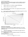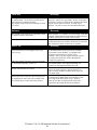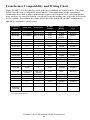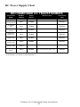
1
Premier 2-4-1A Mountain
Steam Locomotive
OPERATOR’S MANUAL
3
Compatibility
This engine is available in 2-Rail and 3-Rail
versions and will operate on any traditional
O-54 Gauge 3-Rail track system. Or any 54”
radius 2-Rail track system. It is also
compatible with most standard AC
transformers and DC power packs. (See
pages 42 and 43 for a complete
list of compatible AC transformers and DC
power packs.
Passenger Station Announcement
PLEASE READ BEFORE USE AND SAVE
Table of Contents
Configuring Locomotive for 2-Rail or 3-Rail Operation. . . . . . . . . . . . . . . . . . . . . . . . . . . . . . . . . . . . . . . . . . . . 3
Installing/Removing Pickup Rollers. . . . . . . . . . . . . . . . . . . . . . . . . . . . . . . . . . . . . . . . . . . . . . . . . . . . . . . . . . . . . . . 3
Configuring for 2-Rail or 3-Rail Power Input . . . . . . . . . . . . . . . . . . . . . . . . . . . . . . . . . . . . . . . . . . . . . . . . . . . . . . . 3
DCS or DCC . . . . . . . . . . . . . . . . . . . . . . . . . . . . . . . . . . . . . . . . . . . . . . . . . . . . . . . . . . . . . . . . . . . . . . . . . . . . . . . . 4
Installation of Smoke Deflectors . . . . . . . . . . . . . . . . . . . . . . . . . . . . . . . . . . . . . . . . . . . . . . . . . . . . . . . . . . . . . . . . . 4
Proper Coupler Selection . . . . . . . . . . . . . . . . . . . . . . . . . . . . . . . . . . . . . . . . . . . . . . . . . . . . . . . . . . . . . . . . . . . . . . 5
Set Up Checklist. . . . . . . . . . . . . . . . . . . . . . . . . . . . . . . . . . . . . . . . . . . . . . . . . . . . . . . . . . . . . . . . . . . . . . . . . . . . . 8
Placing the Engine on the Track . . . . . . . . . . . . . . . . . . . . . . . . . . . . . . . . . . . . . . . . . . . . . . . . . . . . . . . . . . . . . . . . . 8
PS 3.0 Enhancements. . . . . . . . . . . . . . . . . . . . . . . . . . . . . . . . . . . . . . . . . . . . . . . . . . . . . . . . . . . . . . . . . . . . . . . . 9
Conventional AC/DC Start-up/Shut-down. . . . . . . . . . . . . . . . . . . . . . . . . . . . . . . . . . . . . . . . . . . . . . . . . . . . . . . . . . 9
DCS/DCC Switch. . . . . . . . . . . . . . . . . . . . . . . . . . . . . . . . . . . . . . . . . . . . . . . . . . . . . . . . . . . . . . . . . . . . . . . . . . . . 9
Programming Track (for DCC operation). . . . . . . . . . . . . . . . . . . . . . . . . . . . . . . . . . . . . . . . . . . . . . . . . . . . . . . .. . . 9
Loading DSP and/or Boiler Firmware. . . . . . . . . . . . . . . . . . . . . . . . . . . . . . . . . . . . . . . . . . . . . . . . . . . . . . . . . . . . . 10
LED Lighting. . . . . . . . . . . . . . . . . . . . . . . . . . . . . . . . . . . . . . . . . . . . . . . . . . . . . . . . . . . . . . . . . . . . . . . . . . . . . . . . 10
Modes of Operation. . . . . . . . . . . . . . . . . . . . . . . . . . . . . . . . . . . . . . . . . . . . . . . . . . . . . . . . . . . . . . . . . . . . . . . . . . 10
Conventional AC Operation. . . . . . . . . . . . . . . . . . . . . . . . . . . . . . . . . . . . . . . . . . . . . . . . . . . . . . . . . . . . . . . . . . . . . 10
Conventional DC Operation. . . . . . . . . . . . . . . . . . . . . . . . . . . . . . . . . . . . . . . . . . . . . . . . . . . . . . . . . . . . . . . . . . . . . 11
DCC / Digital Command Control. . . . . . . . . . . . . . . . . . . . . . . . . . . . . . . . . . . . . . . . . . . . . . . . . . . . . . . . . . . . . . . . . 12
F3 Start up / Shut Down. . . . . . . . . . . . . . . . . . . . . . . . . . . . . . . . . . . . . . . . . . . . . . . . . . . . . . . . . . . . . . . . . . . . . . . . 13
Sounds. . . . . . . . . . . . . . . . . . . . . . . . . . . . . . . . . . . . . . . . . . . . . . . . . . . . . . . . . . . . . . . . . . . . . . . . . . . . . . . . . . . . . .13
Lights. . . . . . . . . . . . . . . . . . . . . . . . . . . . . . . . . . . . . . . . . . . . . . . . . . . . . . . . . . . . . . . . . . . . . . . . . . . . . . . . . . . . . . 14
Master Volume. . . . . . . . . . . . . . . . . . . . . . . . . . . . . . . . . . . . . . . . . . . . . . . . . . . . . . . . . . . . . . . . . . . . . . . . . . . . . . . 14
Couplers. . . . . . . . . . . . . . . . . . . . . . . . . . . . . . . . . . . . . . . . . . . . . . . . . . . . . . . . . . . . . . . . . . . . . . . . . . . . . . . . . . . . 14
Forward/Reverse Signal. . . . . . . . . . . . . . . . . . . . . . . . . . . . . . . . . . . . . . . . . . . . . . . . . . . . . . . . . . . . . . . . . . . . . . . . 14
Smoke (If Equipped). . . . . . . . . . . . . . . . . . . . . . . . . . . . . . . . . . . . . . . . . . . . . . . . . . . . . . . . . . . . . . . . . . . . . . . . . . 15
Crossing Signal. . . . . . . . . . . . . . . . . . . . . . . . . . . . . . . . . . . . . . . . . . . . . . . . . . . . . . . . . . . . . . . . . . . . . . . . . . . . . . . 15
Cv29. . . . . . . . . . . . . . . . . . . . . . . . . . . . . . . . . . . . . . . . . . . . . . . . . . . . . . . . . . . . . . . . . . . . . . . . . . . . . . . . . . . . . . . 15
Long and Short Addressing. . . . . . . . . . . . . . . . . . . . . . . . . . . . . . . . . . . . . . . . . . . . . . . . . . . . . . . . . . . . . . . . . . . . . 16
Feature/Factory Resetting. . . . . . . . . . . . . . . . . . . . . . . . . . . . . . . . . . . . . . . . . . . . . . . . . . . . . . . . . . . . . . . . . . . . . . 17
M.T.H. Proto-Sound 3.0 Expanded HO DCC Functionality. . . . . . . . . . . . . . . . . . . . . . . . . . . . . . . . . . . . . . . . 18
Advanced DCC Operation. . . . . . . . . . . . . . . . . . . . . . . . . . . . . . . . . . . . . . . . . . . . . . . . . . . . . . . . . . . . . . . . . . . . . . 18
Additional F Functions. . . . . . . . . . . . . . . . . . . . . . . . . . . . . . . . . . . . . . . . . . . . . . . . . . . . . . . . . . . . . . . . . . . . . . . . . 18
Configuration Variables. . . . . . . . . . . . . . . . . . . . . . . . . . . . . . . . . . . . . . . . . . . . . . . . . . . . . . . . . . . . . . . . . . . . . . . . 20
Advanced Consisting. . . . . . . . . . . . . . . . . . . . . . . . . . . . . . . . . . . . . . . . . . . . . . . . . . . . . . . . . . . . . . . . . . . . . . . . . . 24
Programming Track. . . . . . . . . . . . . . . . . . . . . . . . . . . . . . . . . . . . . . . . . . . . . . . . . . . . . . . . . . . . . . . . . . . . . . . . . . . 28
®
Proto-Sound 3.0 Operating Instructions. . . . . . . . . . . . . . . . . . . . . . . . . . . . . . . . . . . . . . . . . . . . . . . . . . . . . . . . 30
Activating Proto-Sound® 3.0 Conventional Mode Features. . . . . . . . . . . . . . . . . . . . . . . . . . . . . . . . . . . . . . . . . . . . . 30
PSA/FYS . . . . . . . . . . . . . . . . . . . . . . . . . . . . . . . . . . . . . . . . . . . . . . . . . . . . . . . . . . . . . . . . . . . . . . . . . . . . . . . . . . . .32
Proto-Coupler™ Operation . . . . . . . . . . . . . . . . . . . . . . . . . . . . . . . . . . . . . . . . . . . . . . . . . . . . . . . . . . . . . . . . . . . . . .33
Speed Control . . . . . . . . . . . . . . . . . . . . . . . . . . . . . . . . . . . . . . . . . . . . . . . . . . . . . . . . . . . . . . . . . . . . . . . . . . . . . . . 34
Locking Locomotive Into A Direction . . . . . . . . . . . . . . . . . . . . . . . . . . . . . . . . . . . . . . . . . . . . . . . . . . . . . . . . . . . . . 34
Reset To Factory Default . . . . . . . . . . . . . . . . . . . . . . . . . . . . . . . . . . . . . . . . . . . . . . . . . . . . . . . . . . . . . . . . . . . . . . . 35
Automatic Sound Effects . . . . . . . . . . . . . . . . . . . . . . . . . . . . . . . . . . . . . . . . . . . . . . . . . . . . . . . . . . . . . . . . . . . . . . . 35
Maintenance. . . . . . . . . . . . . . . . . . . . . . . . . . . . . . . . . . . . . . . . . . . . . . . . . . . . . . . . . . . . . . . . . . . . . . . . . . . . . . . . 36
Lubricating and Greasing Instructions . . . . . . . . . . . . . . . . . . . . . . . . . . . . . . . . . . . . . . . . . . . . . . . . . . . . . . . . . . . . 36
Cleaning The Wheels, Tires and Track . . . . . . . . . . . . . . . . . . . . . . . . . . . . . . . . . . . . . . . . . . . . . . . . . . . . . . . . . . . . 37
Traction Tire Replacement Instructions . . . . . . . . . . . . . . . . . . . . . . . . . . . . . . . . . . . . . . . . . . . . . . . . . . . . . . . . . . . 37
ProtoSmoke™ Unit Operation . . . . . . . . . . . . . . . . . . . . . . . . . . . . . . . . . . . . . . . . . . . . . . . . . . . . . . . . . . . . . . . . . . 38
®
Troubleshooting Proto-Sound 3.0 Problems . . . . . . . . . . . . . . . . . . . . . . . . . . . . . . . . . . . . . . . . . . . . . . . . . . . . . . . 40
Transformer Compatibility and Wiring Chart . . . . . . . . . . . . . . . . . . . . . . . . . . . . . . . . . . . . . . . . . . . . . . . . . . . . . . 42
DC Power Supply Chart . . . . . . . . . . . . . . . . . . . . . . . . . . . . . . . . . . . . . . . . . . . . . . . . . . . . . . . . . . . . . . . . . . . . . . . 43
Additional Features Accessible Of DCS Remote Control System . . . . . . . . . . . . . . . . . . . . . . . . . . . . . . . . . . . . . . . 44
Service & Warranty Information . . . . . . . . . . . . . . . . . . . . . . . . . . . . . . . . . . . . . . . . . . . . . . . . . . . . . . . . . . . . . . . . . 45
.
Limited One-Year Warranty . . . . . . . . . . . . . . . . . . . . . . . . . . . . . . . . . . . . . . . . . . . . . . . . . . . . . . . . . . . . . . . . . . . . . 45
CAUTION: ELECTRICALLY OPERATED PRODUCT:
Recommended for Ages 14 and up. Not recommended for children under 14 years of age without adult supervision. As
with. all electric products, precautions should be observed during handling and use to prevent electric shock.
WARNING: When using electrical products, basic safety precautions should be observed, including the following:
Read this manual thoroughly before using this device.
M.T.H. recommends that all users and persons supervising use examine the hobby transformer and other electronic equipment
periodically for conditions that may result in the risk of fire, electric shock, or injury to persons, such as damage to the primary cord,
plug blades, housing, output jacks or other parts. In the event such conditions exist, the train set should not be used until properly
repaired.
l
Do not operate your layout unattended. Obstructed accessories or stalled trains may overheat, resulting in damage to your layout.
l
This train set is intended for indoor use. Do not use if water is present. Serious injury or fatality may result.
l
Do not operate the hobby transformer with damaged cord, plug, switches, buttons or case.
l
This product may be protected by one or more of the following patents: 6,019,289; 6,280,278; 6,281,606; 6,291,263;
6,457,681; 6,491,263; 6,604,641; 6,619,594; 6,624,537; 6,655,640.
©2011, M.T.H. Electric Trains®, Columbia, MD 21046
Configuring Locomotive for
2-Rail or 3-Rail Operation
Installing/Removing 3-Rail Pickup Rollers
Both 2-Rail and 3-Rail versions of
this locomotive can be configured
to operate on either 2-rail or 3-rail
track by removing or adding the
center rail pickups. 3-rail track
operation requires the pickups,
2-rail track operation does not.
The pickups are factory installed on
3-rail versions and packaged
separately in the locomotive box for
2-rail versions. Each pickup roller
installs with a single Phillips screw
seen in Figure 1.
Phillips Screw
Phillips Screw
Figure 1: 3-Rail Pickups installed with a single Phillips Screw
Configuring for 2-Rail or 3-Rail Power Input
2-Rail/3-Rail Switch
Once you have configured the
engine for 2-rail or 3-rail operation,
you must manually select the
power input switch located in the
first tender top hatch for 2-rail
operation as seen in Figure 2.
Figure 2: Selecting 2-rail or 3-rail power input setting
Premier 2-4-1A Mountain Steam Locomotive
3
DCS or DCC
If you are operating with command control you must set the selector switch to DCC for
DCC operation and DCS for DCS operation. Refer to page 9 to see and learn about the
differences.
DCS/DCC Switch
Figure 3:
DCS/DCC Switch
CAUTION:
Do not apply DCS signals and DCC signals to the same track simultaneously. The
signals are not compatible, mixing the DCS and DCC signals will damage the DCS
TIU unit.
Smoke Deflector Installation
The smoke deflectors are supplied in the package to prevent damage in shipping.
The smoke deflectors are marked L for the left side and R for the right side and are
easily installed with the supplied screws.
Insert the tab at the end of the support into the slot on the inner side of the smoke
deflector. Then align the holes in the base of the smoke deflector with the holes in the
running boards and insert the supplied screws from the under side of the running
board.
Smoke Deflectors
Location of screws
Premier 2-4-1A Mountain Steam Locomotive
4
Coupler Systems
The Chapelon Pacific is packaged with 4
different coupling systems.
- European Fine Scale Coupler System
- MTH Remote-Controlled Proto Coupler
- Ace Trains compatible coupler
- Kadee type mounting bracket (Scale
Wheel versions only)(Couplers not provided)
All versions have the European Fine Scale
Coupler mounted on the front pilot beam.
Coupling Systems
Two tender pilot beams are provided. One is for use with the European Fine Scale
Coupler. The other pilot is used for the MTH Proto-Coupler, The ACE Trains type
coupler and the Kadee type coupler
All versions have an ACE Trains type coupler in the packaging that can mounted on
the tender truck.
The Scale Wheeled Tender has the European Fine Scale Coupler mounted on the
rear pilot beam. An M.T.H. Remote-Control Proto Coupler is provided in the
packaging along with the an 2nd Pilot Beam that is required to install the coil coupler.
In addition a mounting bracket is supplied for mounting a Kadee style coupler on
the tender.
The Hi-rail Wheeled Tender has an MTH Remote Controlled Proto Coupler
mounted on the rear tender truck. A European Fine Scale Coupler is provided in the
packaging along with correct pilot beam need to mount the European Fine Scale
Coupler.
To remove or install the MTH Remote-Controlled Proto Coupler the tender shell
must be removed to unplug or connect the coupler control wires to the Proto
Coupler.
European Fine Scale Coupler
Premier 2-4-1A Mountain Steam Locomotive
5
Optional Tender Couplers
Kadee® Coupler Bracket Installed
Ace Trains Coupler
Remote Controlled Proto-Coupler
Proto-Coupler Installation
Owners of 2-rail models who intend to run this locomotive on a 3-rail layout may
wish to use the M.T.H. Proto-Coupler so that they may enjoy the remote
uncoupling anywhere on the layout.
A Proto-Coupler and the necessary mounting hardware are included in the
packaging with each 2-rail locomotive. The wire harness in the tender is prewired
with a plug-in connection for the Proto-Coupler.
To install the Proto-Coupler on a 2-rail tender, follow the step by step instruction
listed below.
- First remove the Fine Scale European Coupler and pilot beam from the bottom
of the tender chassis.
- Install the optional pilot beam with no coupler installed
- Next remove the shell from the tender by removing the 4 body screws and then
unplug the wire harness between the shell and the chassis.
Premier 2-4-1A Mountain Steam Locomotive
6
- Attach the proto-coupler to rear tender truck as shown.
- Plug the Proto-Coupler to the black connector provided.
- Reconnect the wire harness between the tender chassis and the tender shell.
- Reattach the tender shell. Remember that the front step piece goes under the
chassis.
When power is applied to the engine the Proto-Coupler can be operated anywhere
on the layout. To operate the coupler in the command mode, press the rear coupler
button on the DCS remote each time you want the coupler to open.
To operate the coupler in the conventional mode, the coupler can be opened by
quickly pressing the Bell Button and Horn Button (1 Bell and 3 Horns) on a Z4000 or compatible Toy Train Transformer. Refer to the Proto-Sound 3.0
Operating Instructions on page 19.
Premier 2-4-1A Mountain Steam Locomotive
7
Placing The Engine On The Track
Your MTH steam engine is equipped with a tetherless drawbar. There is no unsightly
cable or box showing between the engine and the tender to detract from the appearance
of the model. The electrical connections pass through conductors in the drawbar, so it is
important that the connector be properly inserted. The connector is fixed to the rear end
of the drawbar. The mating connector is attached to a swivel connection on the front of
the tender frame. The drawbar is connected to the engine chassis with a screw and
should not need any attention.
In order to mate the connectors of the drawbar and the tender, place the engine and the
tender on the track. Position the tender over the drawbar connector and insert the
drawbar pin on the swivel connector into the hole in the drawbar.
Now grasp the tender with both hands as shown below (in Fig. 8) and place a finger on
each side of the drawbar near the connector. Now using your fingers, push the
connectors together. The connector will make a slight click when it is properly
seated(in Fig. 9). At this point you are ready to begin operating your engine.
Fig. 8: Pushing Connectors Together
Fig. 9: Connected Engine and Tender
To disconnect the engine and tender apply downward pressure near the tender until the
connectors separate.
The drawbar is able to withstand a 90 degree twist such as might be experienced in a
derailment where the engine or the tender would turn over and the other unit would
remain upright.
If the drawbar is not properly connected your engine may exhibit erratic or no
operation. If this happens turn off the track power and make sure that the drawbar
connectors are properly seated. Then reapply power to the track and continue
operation.
Premier 2-4-1A Mountain Steam Locomotive
8
PS 3.0 Enhancements
Here are some of the exciting changes incorporated into your new MTH Proto-Sound®
3.0 Locomotives. More advanced features such as Custom Speed Tables and Advanced
Consisting can be found in the DCC section of this manual.
Conventional (Analog) AC/DC Start-up/Shut-down
Your new MTH PS3.0-equipped locomotive no longer has batteries. It uses Super
Capacitors to hold the engine board alive for a short time when you shut off or interrupt
track power. Because of this, when you first apply track power to your PS3.0-equipped
O Gauge engine, you will notice the headlight comes on but nothing else. This is
perfectly normal. The capacitors are charging up during this time. The wait time
depends upon how long it’s been since you last applied power to the engine. Typically
it will take 1-15 seconds to fully charge. NOTE: The 1-15 second charging wait time
ONLY applies to conventional AC track power.
Once the headlight shuts off, the engine will play its start-up sounds and all the lights
will come back on, simultaneously. Smoke too if you have it turned on.
The capacitors hold enough charge to play the full shut-down sounds. Also, the
capacitors allow you to operate your engine in conventional mode just like you would
any other conventionally-controlled engine. Finally, because there are no batteries, you
will notice there is no external charge jack on the engine.
DCS/DCC Switch
Your MTH PS3.0-equipped engine has a DCS/DCC selector switch (located on the
underside of the tender in steam engines). To operate the engine in DCS mode, ensure
the switch is set to DCS. If you wish to run the engine in DCC mode, ensure the switch
is set to DCC.
If you inadvertently leave the switch in DCC it won’t hurt anything, you just won’t be
able to communicate with your engine with your DCS system. Likewise, if you leave
the switch in DCS and try to operate the engine under DCC you may notice a humming
coming from your engine and you will likely notice that your DCC system’s overload
light will be on.
Programming Track (for DCC operation)
Your MTH PS3.0-equipped O Gauge engine can function on Programming Track
outputs from DCC systems. Most DCC systems can support the current requirements of
the engine as long as it’s not started up. If you plan on powering up the MTH engine on
your programming track, you may want to consider a DCC Programming Track
Booster.
Premier 2-4-1A Mountain Steam Locomotive
9
Loading Tender and/or Boiler Firmware
Your new MTH PS3.0-equipped O-Gauge engine affords you the ability to load DSP
firmware. Additionally, in steam engines you can load boiler firmware. Loader version
2.20 or later will allow you to do this. Please refer to the Loader program’s instructions
for more details. So, as MTH releases new features or updates you will be able to take
full advantage without having to ship your favorite engine anywhere. All new updates
are available on our website. MTH will make announcements as they are available. Not
all updates will apply to all engines. NOTE: Requires a TIU w/ version 4.20 or later
firmware, and requires loader version 2.20 or later.
LED Lighting
Gone are the incandescent bulbs. Your new PS3.0-equipped engine has LED lighting.
MTH uses various colored LEDs to simulate the correct lighting on your engines from
the warm, yellow-orange colored light coming out of an old lantern on your favorite
steam engine to the high-intensity halogen lamp on the latest modern diesels, LED's
allow for various, correct colors. Also, they require less power and do not emit as much
heat as incandescent bulbs.
Modes of Operation
There are 4 options for operating your MTH Proto-Sound® 3.0-equipped engine;
-Conventional AC
-Conventional DC
-DCS - MTH Digital Command System
-DCC
When the locomotive is placed on the track and power is applied to the track the
locomotive will detect the type of control system being used and respond accordingly.
Below is an overview of the 4 different systems.
NOTE: You’ll need to have the DCC/DCS switch set correctly if your using one of
those two modes.
Conventional AC Operation
When using conventional AC power, the engine will respond to changes in track
voltage. An increase in track voltage will increase the locomotive speed and a reduction
in track voltage will reduce the engine speed.
A short interruption (approximately 1 to 2 seconds) in the track voltage will cause the
engine to cycle in the sequence for each track voltage interruption (neutral – forward –
neutral – reverse)
Premier 2-4-1A Mountain Steam Locomotive
10
When power is first applied to the track, the locomotive will be silent for a few seconds
until the super capacitors are charged (The super capacitors provide power to the sound
system during direction changes or intermittent drops in track power due to dirty track
on or switches, when operating in conventional mode). When the super capacitors are
charged, all the lights will come on and the engine sounds will start up. There should be
no movement, as the engine is in neutral. Causing a short interruption of track power
by using the direction button on the transformer, or by turning the throttle off and then
back on again, will change the sequence to the forward state. Then increasing the
throttle will begin to move the engine forward, and speed will increase as the throttle is
advanced.
If there is another interruption in track power the sequence will change to the neutral
position again. The engine will remain in the neutral state until there is another
interruption in track power. The next interruption in track power will move the
sequence to the reverse state. The engine will now move in the reverse direction. If the
power interruption was accomplished by using the direction button and the throttle
position was not changed, the engine will run in the reverse direction at the same speed
that it was traveling in the forward position.
Subsequent interruptions in track power of 1-2 seconds will continue the sequence
rotation. If you happen to interrupt track power for longer than about 2 seconds, the
engine will begin its shut down sounds. If this occurs you can cycle the direction
sequence again to get back to the direction you wish to move and once the engine starts
moving its shut down sounds will stop playing.
In conventional AC operation the whistle sound, the bell sound, PFA sounds and other
operational functions can be accessed if your transformer has a horn/whistle button and
a bell button. By using combinations of button presses, different commands besides
blowing the whistle and ringing the bell can be initiated.
See page 14 for activating Conventional AC Features
Conventional DC Operation
Your MTH locomotive will operate on conventional DC track voltage also. However,
functions such as blowing the whistle, ringing the bell, and the PSA sounds cannot be
initiated in conventional DC. Only the steam chuffing sounds with synchronized
puffing smoke, squealing brake sounds, and idle sounds will function.
Operation of your MTH Proto-Sound 3.0 engine in conventional DC is very similar to
operating a conventional AC engine. As you increase track voltage, engine speed
increases.
As the track voltage is decreased, engine speed is decreased. When track voltage
polarity is reversed using the direction button on the power pack, the engine will run in
the opposite direction. The electronics in your MTH Proto-Sound 3.0 locomotive are
designed to slowly change direction without a need to change the throttle, if you so
desire.
Premier 2-4-1A Mountain Steam Locomotive
11
Just change the polarity switch on your DC power pack and the engine will gradually
come to a stop and then automatically begin traveling in the opposite direction. The
speed will build up to the same speed that the engine was going in the previous direction.
When power is first applied to the locomotive, the engine’s sounds will start up when the
track voltage reaches about 8 VDC. To get your locomotive moving, after the startup
sounds have finished and the locomotive is idling, slowly increase the track voltage until
the locomotive is traveling at the desired speed.
DCC - Digital Command Control
DCC is a popular digital command scheme wherein the track power is also a digital
control signal. That is, using a DCC controller, you can communicate with multiple
engines and have all of them moving at different speeds and in varying directions
on the same track at the same time. The power/command signal remains constant
and engines are commanded to perform as desired. Your MTH PS3.0-equipped
engine has the ability to decode and respond to these DCC commands. This allows
you to mix and match MTH PS3—equipped engines as well as operate them with
any other manufacturer's DCC-decoder equipped engine. The best part about your
MTH PS3.0-equipped engine is that the decoder is built right in. No need to
remove the hood and install speakers or boards. It's all done for you at the factory.
Each PS3.0-equipped engine has a full complement of lights, sounds, smoke (if
equipped). Just set the model on the rails, apply DCC power and hit F3 on your
DCC handheld controller and you're off and running.
Basic DCC Operation:
Your MTH PS3.0-equipped engine takes full advantage of DCC's capabilities.
Below are the basic commands you'll want to know to get started running quickly.
Please refer to the Advanced DCC Operation section of the manual if you want to
dig into the full capability of DCC.
Each engine type may have a slightly different F Function list. This depends upon
whether it's steam, diesel, or electric and whether it has smoke or not. Please refer
to the table of Default CV Values for your particular engine's F Functions.
A note about enabling/disabling F Functions in DCC - Depending upon the DCC
system you have you may need to toggle a particular F Function on then off to
actually get it to enable. Some DCC systems do this for you automatically and
others allow you to set particular F Function buttons to either be set for momentary
or toggle. Please refer to your DCC control station manufacturer's manual for more
information on how they handle F Function buttons.
Premier 2-4-1A Mountain Steam Locomotive
12
Your MTH PS3.0-equipped engine's default short address is 3. So all you
have to do is power up your DCC system and call up Locomotive 3 to begin.
Start-Up/Shut-Down
F3 – Pressing this twice (toggle on then off) will start up your engine. When you
apply DCC power your MTH PS3.0-equipped engine will remain dark and quiet.
Since you likely don't want to run the engine this way, simply press F3 twice to
start your engine. The lights, sound and smoke (if equipped) will come on.
Note – You are actually able to move the engine in DCC without starting it up.
Just increasing the throttle will cause the engine to move. In order for F3 to
function correctly the engine must NOT be moving
To shut your engine down, press the F3 button twice. This will play the shut
down sounds and then turn the lights and smoke and sounds off. As long as there
is DCC power still on the track the engine can be started up again by pressing the
F3 button twice.
Bell/Whistle (Horn)
F1 – Bell. To activate the Bell press F1. To deactivate it, hit F1 again
F2 – Whistle (Horn). To activate the Whistle/Horn, press F2. To shut it off either
let off the F2 button or press and release it
PFA
F4 – PFA. PFA in MTH lingo stands for Passenger/Freight Announcements. Your
engine is pre-programmed for the appropriate type of sounds based upon the type
of service the real-life engine used in daily operation.
There are five sound sequences or segments in the PFA feature. Each segment is
advanced by you, the operator. You hit the Direction button on the DCC
controller to let the engine know you want it to advance. In most PFA sequences
there is a minimum wait time of about 10 seconds before it will advance. So,
here is how a typical PFA sequence operates:
1.
Press the F4 button twice (toggle F4 on then off) to start the PFA
sequence on the engine. You'll hear “Now arriving…”
2.
Press the F4 button twice (toggle F4 on then off) again to stop the engine
at the station. It is recommended to do it this way rather than bring the engine to a
stop with the throttle since PFA allows automatic departure (movement) of the
engine after the last F4 toggle. You'll hear the engine sounds switch from the cab
to the station with all the ambient station sounds you'd hear in the real thing
Premier 2-4-1A Mountain Steam Locomotive
13
3.
Press the F4 button twice (toggle F4 on then off) again to advance the
sequence. You'll hear “Now boarding…”
4.
Press the F4 button twice (toggle F4 on then off) again to advance the
sequence. You'll hear “Now departing…”
5.
Press the F4 button twice (toggle F4 on then off) the last time to advance
the sequence. You'll hear “All aboard…” the engine sounds will switch over to
the cab again and the engine will pull away at the same speed it entered the
station. For a few seconds the bell will ring as it's departing the station
Note – In order to maximize the realism, we recommend that you reduce the
engine's speed to a slow pace just prior to hitting the F4 button the first time (to
activate PFA)
Lights
F5 – Lights. This toggles all your lights (except the headlight) on and off
Master Volume
F6 – Master Volume. There are 10 volume levels. Pressing F6 twice (toggling on
then off) raises the Master Volume one level. The Master Volume loops. That is,
if you go past the 10th level it will loop back around to the 1st or lowest volume
level.
Couplers
Your MTH PS3.0-equipped engine comes with remotely controlled ProtoCouplers. They can be fired using your DCC handheld.
F7 – Rear Coupler. Pressing F7 twice (toggling on then off) will fire your Rear
Coupler
Forward/Reverse Signal
Just like a real engine, you can announce the direction of travel using your DCC
handheld and F9 and F10.
F8 – Forward Signal. Pressing F8 twice (toggling on then off) will sound the
Forward Signal. This is two whistle/horn blasts
F9 – Reverse Signal. Pressing F9 twice (toggling on then off) will sound the
Reverse Signal. This is three whistle/horn blasts
Premier 2-4-1A Mountain Steam Locomotive
14
Smoke (if equipped)
You can control PS3.0-equipped engines that have smoke by toggling F10 on or
off. You can also adjust the smoke output using F11. Some engines have a switch
to enable/disable smoke and others have a smoke volume pot. In the case of a
switch, ensure the switch is set to ON and in the case of a smoke volume pot,
ensure the pot is turned fully clockwise to enable smoke operation in DCC.
F10 – Smoke On/Off. Enabling F10 will turn the smoke unit on. Disabling F10
will turn your smoke unit off.
F11 – Smoke Volume. There are three smoke volume levels in your MTH PS3.0equipped engine – Low/Med/High. The default for this is set to High. You can
adjust the smoke output (amount of smoke the generator puts out) by pressing
the F11 button twice. This sets the level to the next step. For example, if you are
currently at the High smoke output level, pressing F11 twice (toggling it on then
off) will set the smoke volume to Low. Pressing F11 twice again will set it to
Medium and so on.
Crossing Signal
Again, just like a real engine, you can trigger the Crossing Signal on your
engine. This is two long, one short, one long whistle/horn blast.
F12 – Crossing Signal. Pressing F12 twice (toggling on then off) will sound your
Crossing Signal.
Engine Sounds – F18. You can turn the Engine Sounds On/Off by pressing the
F18 button. Pressing it once (enabling F18) will cause the Engine Sounds to shut
off. The Whistle/Horn and Bell sounds will still be active, however. To turn the
engine sounds back on press the F18 button again (disable F18).
CV29
CV29 is the basic decoder setup CV that is used by all DCC decoder
manufactures. So, if you are familiar with CV29 from other manufacturer's
decoders MTH's is no different. The most important part of CV29 is the ability
to switch between long and short addressing. By default, CV29 on your MTH
PS3.0-equipped engine is set to 2.
Premier 2-4-1A Mountain Steam Locomotive
15
Long and Short Addressing
Like most DCC Decoders, your MTH PS3.0-equipped engine can be
programmed with both Long and Short Address. Short addresses are those from
1-127 and Long addresses are those from 128-9999. You can program the engine
address either with Programming on the Main (PoM) or using a Programming
Track. Since it's easiest, in most cases, to PoM the instructions will show you
how to do it this way.
By default, your MTH PS3.0-equipped engine comes programmed with both a
long and short DCC address. The default Short address is always 3. The default
Long address will either be the cab number (if the engine's cab number is
128 or higher) or it will be 3333.
To change your engine's Short Address using PoM:
1.
Call up the engine's current address on your DCC handheld
2.
Enter Programming on the Main on your DCC handheld
3.
Enter the new address you want – Remember you can only use address
1-127 for Short Addressing
4.
Once you hit Enter the engine will give you a two whistle/horn blast
response
5.
Call up the engine on its new address and away you go
Alternatively, depending upon the type of DCC system you have, you can enter
PoM and then write the new address in the Address Menu. This only works for
short addressing. For example, on an MRC Prodigy Advance2 system, you
would:
1.
Call up the engine's current address on your DCC handheld
2.
Hit the PROG button twice to enter PoM mode
3.
Hit Enter twice so the LCD displays “Adr”
4.
Type in the new Short Address (1-127) that you want and hit Enter
5.
The engine will give you a two whistle/horn blast response
Premier 2-4-1A Mountain Steam Locomotive
16
To change your engine's Long Address using PoM:
1.
Call up the current engine's address on your DCC handheld
2.
Enter Programming on the Main on your DCC handheld
3.
In this step you have to tell the MTH engine that you want it to start
looking at long addresses. You do this in Cv29:
a.
b.
c.
d.
4.
Bring up the CV menu on your DCC handheld
Enter”29” to edit CV29
Enter “36” to change the value of CV29 and hit Enter
The engine will give you a two whistle/horn blast response
In the following steps you will now need to write values to CV17 and
CV18 to tell the engine what the long address should be
Feature/Factory Resetting
If all else fails and you aren't sure of something, never fear. You can
always get your engine back to a known state by either performing a
Feature or Factory Reset.
There are a couple of ways to reset your MTH PS3.0-equipped engine:
?
Factory Resets – Clears everything – takes engine to just like it was when
you got it brand new
o
Send a decimal 08 to CV 8 to reset everything entirely
back to factory default
o
Send a decimal 192 to reset everything except user speed
tables
?
Feature Resets – There are a couple of Feature Resets that you can use
o
Press F21 twice (toggling on then off). This resets the
smoke, volume and lights back to their defaults
o
Send a decimal 64 for a Feature Reset. This resets
volumes, smoke and light settings.
o
Send a decimal 128 to reset only address values back to
factory default
?
This is the same as writing 55 to CV55 to engine
address 55
Premier 2-4-1A Mountain Steam Locomotive
17
MTH PS3.0 Expanded HO DCC Functionality
Advanced DCC Operation:
This section of the manual provides more in-depth detail on how to set up and
configure your MTH PS3.0-equipped engine using the NMRA-standard CV's as
well as the manufacturer-specific CV's. It also explains some of the other F
Functions not covered in the Basic DCC Operation section.
Additional F Functions
Idle Sequence - F22-F25. Pressing F22, F23, F24, or F25 twice (toggling on then
off) will trigger an Idle Sequence if the engine is not moving. These vary from
engine to engine and may include things like checking the coal load, checking the
water level, using the Alemite grease gun on the drivers, etc. When triggered,
these will run through the sequence that varies in duration.
Note – The engine must be sitting still in order to trigger these
Coupler Slack – F13. When an engine hooks up and pulls a train it has to take up
the coupler slack. You can play this sound by pressing F13 twice (toggling on
then off). This feature works two ways – While the engine is sitting still, press
F13 twice to enable it.
Then, when you move the engine, it will play the Coupler Slack sound. The
second way is to simply force the sound while the engine is moving. To do this,
simply press F13 twice (toggling it on then off). The sound will play.
Extended Start-Up – F14. If your engine is shut down or you've just applied DCC
power pressing F14 twice (toggling it on then off) will start the Extended StartUp sounds. This is very similar to F3 except you will hear the crew talking back
and forth about getting the engine ready to run.
Extended Shut-Down – F15. If your engine is already up and running you can
play the Extended Shut Down sounds by pressing F15 twice (toggling on then
off). The Extended Shut Down is very similar to F3 in that the engine will
ultimately shut down but in the case of Extended Shut Down you will hear the
crew talking back and forth about how the engine ran, time schedules, etc.
Rev Up/Labor Chuff – F16. Depending upon the engine type you have
Diesel/Electric or steam you can either force the engine to Rev Up
(Diesel/Electric) or force the engine to play its Labor Chuff sounds. For a
Diesel/Electric, press the F16 button twice (toggling on then off) to Rev Up one
notch. There are eight rev levels in a Diesel/Electric.
Premier 2-4-1A Mountain Steam Locomotive
18
To force the Labor Chuff sound in a steam engine, press the F16 button
once (enable F16). As long as F16 is enabled the engine will play its
Labor Chuff sounds. To set the sound back to Normal Chuff press the F16
button again (disable F16).
Rev Down/Drift Chuff – F17. Depending upon the engine type you have
Diesel/Electric or steam you can either force the engine to Rev Down
(Diesel/Electric) or force the engine to play its Drift Chuff sounds. For a
Diesel/Electric, press the F17 button twice (toggling on then off) to Rev
Down one notch. There are eight rev levels in a Diesel/Electric.
To force the Drift Chuff sound in a steam engine, press the F19 button
once (enable F17). As long as F17 is enabled the engine will play its Drift
Chuff sounds. To set the sound back to Normal Chuff press the F17 button
again (disable F17).
For example, if you set the rev level on a Diesel to notch 6 and start
increasing the speed of the engine it will stay at that rev level until the
engine's speed calls for a higher rev level. Once the engine has gone past
that rev level, notch 6 in this example, the engine will then rev down
normally, all the way to idle, as you decrease the speed.
Single Whistle/Horn Blast – F19. To play a Single Horn Blast press the
F19 button twice (toggling in on then off). This plays a single, short horn
blast.
Coupler Close – F20. To play the Coupler Close sound press the F20
button twice (toggling it on then off). You can play this sound as you're
coupling cars together to add realism.
One Shot Doppler – F26. You can set your MTH PS3.0-equipped engine
to simulate the actual Doppler Effect sound a real engine makes as it
passes you. To do this, press the F26 button once (enable F26) and then
listen as the engine makes that pitch shift that mimics the Doppler Effect
perfectly. Press the F26 button again (disable F26) to shut off the Doppler
Effect. With a little practice in timing and speed you can make this happen
right in front of you.
Brake Sounds – F27. Pressing the F27 button (enable F27) will disable the
Brake Sounds for your engine. The Brake Sounds occur when you reduce
the speed of your engine rapidly. To enable the Brake Sounds press the
F27 button (disable F27). Brake Sounds are On by default.
Premier 2-4-1A Mountain Steam Locomotive
19
Cab Chatter – F28. Cab Chatter occurs when the engine is sitting at idle.
There are various times when the crew will talk to each other when the
engine is sitting at idle. Pressing the F28 button (enable F28) will disable
the Cab Chatter. Pressing the F28 button again (disable F28) will enable
Cab Chatter. Cab Chatter is On by default.
Configuration Variables (CV)
Configuration Variables used on MTH PS3.0-equppied engines.
CV1
CV2
CV3
CV4
CV5
CV8
CV17
CV18
CV19
CV21
CV22
CV23
CV24
CV25
CV29
CV52
CV53
CV54
CV55
CV63
CV64
CV66
CV67CV94
CV95
CV105
CV106
CV115CV170
Short Address: 1-127 are the valid addresses
Start Voltage (CV52, bit0 must =1. This will enable PWM Mode)
Acceleration Rate (CV52, bit0 must =1. This will enable PWM Mode)
Deceleration Rate ((CV52, bit0 must =1. This will enable PWM Mode)
Max Voltage (CV52, bit0 must =1. This will enable PWM Mode)
MFG ID. MTH =27. Also used for various resets
High Byte of Extended Address
Low Byte of Extended Address
Consist Address (bit 7=1 on an engine will tell the engine it’s
reversed in a consist)
Defines active Function F1-F8 for the active consist
Defines active functions for FL and F9-F12 for the active consist (bit
0=1 will tell an engine that you want it’s FL control to operate under
the consist address – bit1-0/bit2=1 will configure the FL control for a
reversed engine in a consist)
Consist Acceleration Rate
Consist Deceleration Adjustment
Speed Table Select
Decoder Configuration
MTH PWM Mode Configuration
MTH Acceleration (1/8*sMPH/s). For example – a Value of 8 written
would give you 1sMPH/s acceleration
MTH Deceleration Rate (1/8*sMPH/s)
Factory Reset Alternate method: Send a value of 55 to CV55 on
address 55 and the model will go back to Factory Default
MTH Consist Acceleration Rate (1/8*sMPH/s)
MTH Consist Deceleration Rate (1/8*sMPH/s)
Forward Trim (CV52, bit0 must =1. This will enable PWM Mode)
Speed Table Selection (CV29 bit 4 must be set to 1 then CV25 must
be set to 0 or 1)
Reverse trim (CV52, bit0 must =1. This will enable PWM Mode)
User ID #1 – General Purpose use for customer
User ID #2 – General Purpose use for customer
MTH Function Assignments – See table of supported CV’s and
manual section on how to re-arrange them for further information
Premier 2-4-1A Mountain Steam Locomotive
20
Below is the table of Factory Default MTH supported DCC CV's. This
table is specific to the engine in the title of this manual:
User-Settable F-Function List
This feature allows you to take the 28 F-Functions that currently reside in
each MTH Protosound3.0-equppied O-Gauge Engine and change the
location of that function. For example: F13 is currently Coupler Slack and
you'd like that placed down to F28 which is Cab Chatter. The below
instructions explain how you can do this.
Note – When you set a particular F-Function to a numeric location you
are overwriting that existing number's function. Further, you are leaving
the location where the previous function was moved from empty, which
means that F-Function no longer has any function associated with it.
Premier 2-4-1A Mountain Steam Locomotive
21
In order to move the F-Functions around you will need to refer to the
below table.
Note – The Function Identification number IS NOT the F Function
number you'd use on your DCC handheld. It is used internally in the
engine:
Function Identification Chart
Function
Sounds
Identification
Bell
1
Brake Sounds
2
Cab Chatter
3
Clickety Clack
4
Coupler Close
5
Coupler Slack
6
Drift Chuff
7
Engine Sounds
8
Forward Signal
9
Crossing Signal
10
Horn
11
Idle Sequence 1
12
Idle Sequence 2
13
Idle Sequence 3
14
Idle Sequence 4
15
Labor Chuff
16
Master Volume
17
Short Horn
18
One Shot Doppler
19
Reverse Signal
20
Scripts
Extended Shut Down
Extended Start Up
PFA
Start Up/Shut Down
Train Wreck
Trolley Manual Mode
Trolley Learn More
Trolley Auto Mode
Other Functions
Feature Reset
Front Coupler
Front Pantograph
Up/Down
Pantograph
Auto/Manual
Rear Coupler
Rear Pantograph
Up/Down
Rev Down
Rev Up
Smoke On/Off
Smoke Volume
Lights
Lights
21
22
23
24
25
26
27
28
29
30
31
32
33
34
35
36
37
38
39
Premier 2-4-1A Mountain Steam Locomotive
22
The above list includes ALL F functions that an MTH PS3 engine
could have. You are free to change any of the above listed items to
any F function position, 1-28. For example, if you your engine came
from the factory without a smoke unit but you added one at a later
date you could swap out any of the F functions, 1-28, for the Smoke
On/Off and the Smoke Volume.
So, using the example above of moving F13 to F28 here are the
steps:
1.
Refer the MTH Supported CV table to see what CV the
destination Function is assigned to. In doing so, you are looking
only for the Low Byte CV location. In this case it's Cv170
2.
Using your DCC system, bring up CV programming for
Cv170
3.
Now tell the engine which F-Function you want to write at
CV170. So, looking at the Function ID table above you can see that
Coupler Close is a value of 5
4.
Using your DCC system, enter a value of 5 for CV170 and
hit Enter. You have just re-assigned the Coupler Slack sound to F28
on your DCC controller. The engine will give you a two horn blast
indication. Note – You've also left an empty location where Coupler
Slack used to be (F13)
5.
Now you can fill that location with whichever CV you'd like.
For this example we are just going to move the Cab Chatter up to
F13 (we're just swapping F13 and F28)
6.
Since F13's Low Byte is CV140 then bring up CV
programming for Cv140
7.
Now tell the engine which F-Function you want to write at
CV140. So, looking at the Function ID table above you can see that
Cab Chatter is a value of 3
8.
Using your DCC system, enter a value of 3 for CV140 and
hit Enter. Your engine will give you a two horn blast indication
Premier 2-4-1A Mountain Steam Locomotive
23
Custom Speed tables
Below is a table that shows the value to write to CV25 to achieve
the desired speed curve. For example, if you would like to use
speed curve 18 then:
1.
Write a value of 1 to CV52 to enable PWM Mode
2.
Write a value of 1 to bit 4 of Cv29
3.
Write a value of 18 to CV25. Your engine will now use the
speed curve #18 below
4.
If you want to create your own speed table using CV's 67-94
then write a value of 0 or 1 to Cv25
Advanced Consisting
Advanced Consisting follows the NMRA standards. Any values
assigned to CV's 21-24 are ignored once the consist is removed
(CV19 set to 0).
?
Setting the MSB (Bit 7) of CV19 tells the engine that it is
facing reverse in the consist
?
Setting CV21 and CV22 determine which F Functions the
consist responds to
See diagram below for example
Premier 2-4-1A Mountain Steam Locomotive
24
F
R
Engine 1 - Front
F
R
Engine 2 - Middle
F
R
Engine 3 - Rear
Normal Forward Direction of Travel
To set this consists up so that:
?
The Headlight is ON in the Front engine when going
Forward, OFF when the consist is in Reverse
?
The Reverse light and headlight is OFF in the Rear engine
when the consist is going Forward, headlight is ON, reverse light is
OFF when the consist is in Reverse
?
The Middle engine has no lights in either direction
Perform the following:
1.
Build the consist using your DCC system per the DCC
system's manufacturer's instructions. In many newer systems you
have the ability to tell the system which engine is reversed.
Remember the consist address you told the DCC system to be built
at as you'll need to come back to that address to actually run the
consist. The instructions assume only CV19 gets the consists
address and nothing more
2.
Call up the Front engine on your DCC handheld; address 1
in this example
3.
Select CV22 and write a value of 1. This tells the engine that
it's a forward facing engine and that you want F0 to control the FL
function at the consist address. The engine will give you two horn
blasts to announce that it received the CV change
4.
Ensure F0 is deactivated at the Front engine's address. Most
systems have a light bulb icon to indicate whether F0 is active or
not. Ensure that it is OFF
5.
Call up the Rear engine on your DCC handheld; address 3 in
this example
Set CV19 to 128 + the value of your consist address
Premier 2-4-1A Mountain Steam Locomotive
25
a.
So, if your consist address is 4 you would add 128+4=132.
You would write 132 to CV19. This tells the Rear engine that it's
reversed in the consist. You will get two horn blasts to announce
that it received the CV change. Some DCC systems may already
do this for you but the instructions assume your system does not. If
you are in doubt then go ahead and follow step 5 as it will do no
harm
2.
Set CV22 to a value of 2 to the Rear engine's address to tell
the Rear engine that you want to control its FL control with the F0
button at the consist address. The engine will give you two horn
blasts to announce that it received the CV change
3.
Ensure F0 is deactivated at the Rear engine's address. Most
systems have a light bulb icon to indicate whether F0 is active or
not. Ensure that it is OFF
4.
Call up the Middle engine on your DCC handheld; address 2
in this example
5.
Ensure F5 and F0 are toggled OFF. You may have to toggle
F5 on/off a couple times to get the lights in sync with the DCC
command station. This will depend upon your DCC system
6.
Call up the consist address (address 4 in this example)
7.
Press the F0 button to ensure the FL is toggled on. Most
systems have a light bulb icon to indicate whether F0 is active or
not. Ensure that it is ON
Note – The convenient thing about setting up the consist as
described above is that it allows you flexibility in the orientation of
an engine in a consist; particularly the head and tail engines where
the FL control is integral. For example, if you wanted to flip the
Rear engine around and make it face forward in the consist all
you'd have to do is go into the Rear engine's address (address 3 in
the example) and clear bit 7 of CV19. In other words, just write the
consist's address to CV19. The FL control will automatically
understand what you've done so there is no need to go in and
change CV22.
Below is a table that outlines which bits correspond to what F
Functions F0, F9-F12 are used in a consist:
Premier 2-4-1A Mountain Steam Locomotive
26
Bit
(Decimal
Value)
7 (128)
Not
Used
6 (64)
Not
Used
5 (32)
4 (16)
3 (8)
2 (4)
1 (2)
0 (1)
F
Function
Not
Used
Not
Used
F12
F11
F10
F9
F0
(Engine
Facing
Rev)
F0
(Engine
Facing
Fwd)
Setting Up CV21 for a Consist
Cv21 allows you to set which F Functions you want the consist
address to control. For example, you will likely want all of your MTH
consist engines to respond to Start-Up/Shut Down (F3). Also, you'll
likely want at your Front engine to respond to the Bell and Horn
commands (F1 and F2, respectively) and the Front Coupler (F7 on
most MTH models). Likewise, you'll want your Rear engine to
respond to the Rear Coupler command (F8 on most MTH models).
Please refer to the table below to see which bits have what decimal
value and which F Function they correspond to.
To do this:
1.
Call up the Front engine on your DCC system
2.
To set the Front engine to respond to the Bell (F1), Horn
(F2), Start-Up/Shut Down (F3) and Front Coupler (F7) you will want
to write a value of 71 to CV21. This is setting bits 0, 1, 2, and 6 ON.
a.
CV21's bits are shown in the table below – the decimal value
is shown in parenthesis:
Bit
(Decimal
Value)
F
Function
7 (128)
6 (64)
5 (32)
4 (16)
3 (8)
2 (4)
1 (2)
0 (1)
F8
F7
F6
F5
F4
F3
F2
F1
Premier 2-4-1A Mountain Steam Locomotive
27
NOTE - CV21 is ONLY used when you have some value other than
0 written to CV19. If CV19 = 0 then the values of CV21, CV22,
CV23, and CV24 are not used
1.
Call up your Middle engine (address 2 in the example)
2.
Since you want to have the Middle engine respond to F3
only then write a value of 4 (CV21, bit 2 = ON)
3.
Call up your Rear engine (address 3 in the example)
4.
Since you want to have the Rear engine respond to the
Start-Up/Shut Down (F3) and Rear Coupler (F8) functions you
want to write a value of 132 to CV21
Your engines are now set up according to the example above.
You will note that there is no F0 in CV21. This is because that
function (FL) is controlled by CV22. Please refer to the Advanced
Consisting section for more information regarding Cv22.
Programming Track
Your MTH PS3.0-equipped HO engine can function on
Programming Track outputs from DCC systems. Because each
DCC system manufacturer's output capabilities on the
Programming Track differ it is recommended that you use a DCC
Programming Track Booster to perform functions on the
programming track. Simply put – try to program or read back the
address of an MTH engine on a programming track. If you can
read/write the address then you won't need a Programming Track
Booster. If your DCC system can't read/write then you will likely
need a Programming Track booster. There are a few different
manufacturers of these boosters. Your local dealer can provide you
with more information on these boosters. MTH has used the DCC
Specialties Power Pax with some success.
Note – An alternative to writing on a Programming Track is to
simply Program on the Main (PoM). MTH engines support PoM to
write any CV on the main. However, read back is not supported on
the main. Check with your DCC system's manufacturer to see
about any limitations they may have to PoM.
Premier 2-4-1A Mountain Steam Locomotive
28
DCC Bit Value Decoder
Example Value (bit 7 -> bit 0) 11011001
Bit
(Decimal
Value)
Binary
Example
Decimal
Value
7(128) 6(64)
1(on)
128
5(32)
4(16)
3(8)
2(4)
1(2)
0(1)
1(on) 0(off) 1(on) 1(on) 0(off) 0(off) 1(on)
64
0
16
8
0
0
1
So, in the above example you simply add up the values in the
“Decimal Value” row – 128+64+0+16+8 +0+0+1 = 217. You would
write 217 to the CV you were altering.
The above applies to any CV. Also, if you have a CV that already
has a value assigned that you do not want to alter but need to
make additions to it, for example CV29, you would simply add the
additional bits you enabled to the existing value to obtain the new
CV value.
For example, if you had a consist address (CV19) set to 5 and you
wanted to alter this to show an engine reversed in the consist you
would need to set bit 7 (decimal value = 128) for the engine you
want to reverse. To do this - take 128 (the new bit you want to set)
+ 5 (the existing bit that you do not want to alter) = 133. You would
then write a value of 133 to CV19.
Premier 2-4-1A Mountain Steam Locomotive
29
®
Proto-Sound 3.0 Conventional AC
Operating Instructions
Activating Proto-Sound® 3.0 Conventional AC Mode
Features
Throttle - To increase or decrease track voltage, and therefore train speed, turn the
throttle control knob. Turning clockwise will increase voltage and speed, while
turning counterclockwise will decrease voltage and speed. The engine will maintain
the speed you set after you release the throttle until you turn it again to change the
voltage and speed.
Bell - To sound the bell, in an engine equipped with a bell firmly press and release the
Bell button. To turn the bell off, press and release the Bell button again. The bell will
continue to ring from the time you turn it on until you press and release the button
again to turn it off.
Horn/Whistle - To sound the whistle, firmly press the Horn/Whistle button. The
whistle will sound for as long as you continue to depress the button. It will stop when
you release the button.
Direction - Your train is programmed to start in neutral. The train will always cycle
neutral-forward-neutral-reverse with each press and release of the direction button.
The engine is programmed to restart in neutral each time the track voltage is turned off
for 25 seconds or more.
Premier 2-4-1A Mountain Steam Locomotive
30
Cycle Phases
Neutral
Reverse
Forward
Neutral
®
Proto-Sound 2.0
Volume Adjustment
Knob
Manual Volume Control
To adjust the volume of all sounds
made by this engine, turn the master
volume control knob located under the
left water hatch on the tender deck
clockwise to increase the volume and
counter-clockwise to decrease the
volume.
Figure 10: Manually Adjusting the Volume
Proto-Sound® 3.0 features are activated by sequences of Bell and Horn button pushes
described below. Please read the full descriptions of each feature before using it. To
use these buttons to activate features rather than to blow the horn or ring the bell, you
should tap the buttons very quickly with a ½-second pause between button presses.
You may need to practice your timing to make this work smoothly.
Timing Chart
Press
Horn
Short &
Firm
Press
½ Sec.
Bell
Pause
Short &
Firm
Total Time Lapse: 1 ½ Seconds
½ Sec.
Pause
Feature to Be Activated
Freight Yard or Passenger Station Sounds
Fire the Rear Coupler
Fire the Front Coupler
Speed Control On/Off
Lock into a Direction
Reset to Factory Defaults
Press
Bell
Short &
Firm
Button Code:
1 Bell, 2 Horn/Whistles
1 Bell, 3 Horn/Whistles
1 Bell, 4 Horn/Whistles
1 Horn/Whistle, 2 Bells (from Neutral only)
1 Horn/Whistle, 3 Bells
1 Horn/Whistle, 5 Bells (from Neutral only)
Premier 2-4-1A Mountain Steam Locomotive
31
Passenger/ Station Announcements (PSA)/
Freight Yard Sounds (FYS)
Your engine is equipped with a sound package of passenger station announcements that
you can play when you pull into a station. Each sequence described below will play as
long as it is left on, randomly generating sounds, but be sure to allow approximately 30
seconds between the button pushes described below to allow the PSA/FYS sufficient
time to run through each sequence.
•To cue the sound system to play the PSA/FYS, quickly but firmly tap the Bell
button once followed by 2 quick taps of the Horn button while the engine is
moving. Tap the buttons quickly but allow approximately ½ second between
each press.
• Press the Direction button once to stop the engine. This will trigger the first
sequence of PSA/FYS. The reverse unit is temporarily disabled so that the train
will not move as you use the Direction button to trigger the sounds, and ProtoSound 2.0 has disabled operator control over the Horn and Bell buttons until
the full PSA/FYS. sequence is complete.
•After waiting about 30 seconds for that sequence to run, press the Direction
button again to trigger the second sequence of PSA/FYS.
•After about 30 seconds, press the Direction button again to trigger the third
PSA/FYS sequence.
•Again, after allowing about 30 seconds for that sequence to run, press the
Direction button one more time to trigger the fourth and final PSA/FYS
sequence. The PSA/FYS will continue, and within a few seconds, the engine
and bell will start and move out on its own at the current throttle setting, in the
same direction it was traveling when you began the sequence. Once the bell
turns off, the operator regains control of the transformer's bell and Horn
buttons and can ring the bell or blow the Horn as usual.
Bell
Horn/
Whistle
Horn/
Whistle
Sound System Cued to Play
Freight Yard or Passenger
Station Sounds (FYS)/(PSA)
+
Direction
1st
Sequence
FYS/PSA
+
Direction
2nd
Sequence
FYS/PSA
+
Direction
3rd
Sequence
FYS/PSA
+
Direction
4th
Sequence
FYS/PSA
Premier 2-4-1A Mountain Steam Locomotive
32
Operator
Controls
= When
Bell
Turns Off
Tips on Using PSA/FYS
•You can terminate PSA/FYS at any time by turning off power to the track for 15
seconds.
•You do not have to be in Forward to use PSA/FYS. At the conclusion of the full
sequence, the train will pull away from the station in whatever direction you were
going when you activated the feature.
•You can use PSA/FYS even if you are double-heading with another engine. If the
second engine is not equipped with Proto-Sound® 2.0, you must remember not to leave
the throttle at a high voltage level once you have stopped the engine to run the
PSA/FYS. Otherwise, the engine without PSA/FYS will begin vibrating on the track
as its motors strain to move the train, since they cannot be automatically disabled
during the PSA cycle (or if an original Proto-Sound® engine, PSA/FYS are triggered
differently and that engine's motor-disable feature will not be active when you run
PSA/FYS in Proto-Sound® 3.0).
•PSA/FYS can be triggered from Neutral. It will operate the same as if triggered while
in motion except that, at the conclusion of the PSA/FYS, the engine will depart in the
next direction of travel, as opposed to the direction it was traveling before entering
Neutral.
Proto-Coupler® Operation
This locomotive is equipped with one or more coil-wound Proto-Couplers for remote
uncoupling action. Because Proto-Couplers are controlled through the Proto-Sound®
3.0 microprocessor, they do not require an uncoupling track section or modification to
your layout to function. You can fire a coupler from neutral or while in motion. Use the
code shown below (and in the chart on p. 31) to fire the coupler(s).
Rear Coupler:
To fire the rear coupler, quickly tap the Bell button once followed by three quick taps of
the Horn button, allowing approximately ½ second to lapse between each quick button
press. The sound of the liftbar and air line depletion will play, and the knuckle will be
released.
Fire
Bell
Horn
Horn
Horn
Rear
= Coupler
Front Coupler:
To fire the front coupler (if your engine has one), quickly tap the Bell button once
followed by four quick taps of the Horn button, allowing approximately ½ second to
lapse between each quick button press. The sound of the liftbar and air line depletion
will play, and the knuckle will be released.
Fire
Bell
Horn
Horn
Horn
Horn
Front
= Coupler
Premier 2-4-1A Mountain Steam Locomotive
33
Speed Control
M.T.H. engines equipped with Proto-Sound 3.0 have speed control capabilities that
allow the engine to maintain a constant speed up and down grades and around curves,
much like an automobile cruise control. You can add or drop cars on the run, and the
engine will maintain the speed you set.
While the engine is programmed to start with the speed control feature activated, you
can opt to turn it off. This means the engine's speed will fall as it labors up a hill and
increase as it travels downward. It is also affected by the addition or releasing of cars
while on the run. Because the engine will run more slowly at a given throttle voltage
when speed control is on than when it is off, you should adjust the throttle to a lower
power level for operation with speed control off to avoid high-speed derailments.
When speed control is off, the volume will drop to allow for better low voltage
operation.
To turn speed control on and off, put the engine in neutral, then quickly tap the
transformer's Horn button one time then quickly tap the Bell button two times,
allowing approximately ½ second to lapse between each quick button press. Two horn
blasts will indicate that the engine has made the change. Repeat the 1 horn, 2 bells
code to return it to the other condition. You will want to do this during the initial
neutral upon start-up if you ever couple this engine to another engine that is not
equipped with speed control to avoid damaging the motors in either engine. Each time
you shut down the engine completely, it will automatically turn speed control on.
Place
Engine into
Neutral
Horn
Bell
Bell
=
Speed Control
Two Horn Blasts
(indicates change is made)
Repeat to Return
to Normal Condition
Locking Locomotive Into A Direction
You can lock your engine into a direction (forward, neutral, or reverse) so that it will not change
directions. To do this, put the engine into the direction you want (or into neutral to lock it into
neutral), run it at a very slow crawl (as slowly as it will move without halting), and quickly but
firmly tap the Horn button once followed by three quick taps of the Bell button, allowing
approximately ½ second to lapse between each quick button press. Two horn blasts will indicate
that the engine has made the change. The engine will not change direction (including going into
neutral) until you repeat the 1 horn, 3 bells code to return the engine to its normal condition, even
if the engine is kept without power for extended periods of time.
Place
Engine into
Desired
Direction
Horn
Horn
Bell
Bell
Bell
=
Direction Lock
Two Horn Blasts
(indicates change is made)
Repeat to Return
to Normal Condition
Premier 2-4-1A Mountain Steam Locomotive
34
Reset to Factory Default
To override the settings you currently have assigned to the engine and reset it to its
factory defaults, while in Neutral tap the Horn button quickly once, followed by five
quick taps of the Bell button, allowing approximately ½ second to lapse between each
quick button press. Two horn blasts will indicate that the engine has made the change.
Place
Engine in
Neutral
Horn
Bell
Bell
Bell
Bell
Bell
=
Reset
Two Horn Blasts
(indicates change is made)
Repeat to Return
to Normal Condition
Automatic Sound Effects
Certain Proto-Sound® 3.0 sound effects automatically play in programmed
conventional mode conditions:
•Squealing Brakes play any time the engine's speed decreases rapidly.
•Cab Chatter plays at random intervals when the engine idles in neutral.
•Engine Start-up and Shut-down sounds play when the engine is initially
powered on or is powered off for five seconds or more.
Premier 2-4-1A Mountain Steam Locomotive
35
Maintenance
Lubricating and Greasing Instructions
The engine should be well oiled and greased in order to run properly.
You should regularly lubricate all side rods, linkage components and
pickup rollers to prevent them from squeaking. Use light household oil
and follow the lubrication points marked “L” in Fig. 7. Do not over-oil.
Use only a drop or two on each pivot point.
Body Mount Screws
Figure 11: Removing the Body
Body Mount Screw
Pivot Screw
The locomotive’s internal gearing was greased at the factory and should not need
additional grease until after 50 hours of operation or one year, whichever comes first.
To access the gear box and axles, do the following:
1. Turn the engine upside down.
2. Remove the Phillips screws (marked “GREASE”). One is located directly under the
front pick up roller. The other is located in the center of the drive wheels.
3. Use a grease tube dispenser to put a small amount (approx. 1-2 ml.) of lithium-based
grease into the gearbox and axles.
4. Replace the screws.
You should also grease the leading and trailing locomotive truck tongues to enhance
their ability to slide on the chassis. Follow the grease points shown on Fig. 12.
Premier 2-4-1A Mountain Steam Locomotive
36
Grease Screws
Grease Pivot Screw (G)
Apply Oil to the Control Pin
Body Mount Screws
Figure 12: Lubricating The Grease Points
Cleaning the Wheels, Tires and Track
Periodically check the locomotive wheels and pickups for dirt and buildup, which can
cause poor electrical contact and traction as well as prematurely wear out the neoprene
traction tires.
Wheels and tires can be cleaned using denatured (not rubbing) alcohol applied with a
cotton swab.
Tire Traction Replacement
Instructions
(3-Rail Version Only)
Your 3-rail locomotive is equipped with two neoprene
rubber traction tires on the rear set of flanged drivers.
While these tires are extremely durable, you may need to replace them at some point.
1. Remove the side rods from the wheels in order to slip the new tire over the grooved
drive wheel. Make sure to note the position of all rods before removing.
2. Make sure the old tire has been completely removed from the groove in the drive
wheel, using a razor blade or small flathead screwdriver to pry away any remains.
3. Slip the new tire onto the wheel. You may find it useful to use two small flathead
screwdrivers to stretch the tire over the wheel.
4. If you twist the tire while stretching it over the wheel, you will need to remove and
reinstall the tire. Otherwise your engine will wobble while operating.
5. Make sure the tire is fully seated inside the groove. Use a razor blade to trim away
any excess tire that doesn’t seat itself inside the groove properly.
6. Reinstall the side rods in the same positions as noted. Failure to align rods may
cause binding or damage to the drive system.
One set of replacement tires is packaged with your model. Additional sets are available
directly from the M.T.H. Parts Department (phone: 410-381-2580; e-mail: [email protected]; mail: 7020 Columbia Gateway Drive, Columbia MD 21046-1532).
Premier 2-4-1A Mountain Steam Locomotive
37
ProtoSmoke® Unit Operation
This Premier steam locomotive contains a self-powered smoke unit that outputs smoke
through the smokestack on the roof of the engine. The smoke unit is essentially a
small heating element and wick that soaks up and then heats a mineral oil-based fluid
that emits a harmless smoke. The smoke is then forced out of the stack by a small
electric fan. Smoke volume is controlled by the Proto-Sound® 3.0 system.
With a few easy maintenance steps, you should enjoy trouble-free smoke unit
operation for years.
When preparing to run this engine, add 10-15 drops of smoke fluid through the
smokestack (See figure 16). We recommend M.T.H. ProtoSmoke, Seuthe, LGB, or
LVTS fluids. Do not overfill the unit or the fluid may leak out and coat the interior
engine components.
If you choose not to add the fluid (or have already added the fluid but choose to run
smoke-free), turn off the smoke unit switch located under the water hatch on the right
side of the tender (See figure 17). Failure either to add fluid to the unit or to turn it
off may damage the smoke unit heating element and/or wick material.
When the smoke output while running the engine begins to diminish, add another 1015 drops of smoke fluid or turn the smoke unit off.
When storing the unit for long periods of time, you may want to add about 15 drops of
fluid to prevent the wick from drying out.
After removing the engine from storage, add another 20 drops of fluid, letting the wick
soak up the fluid for 15 minutes prior to operation.
Add 15 - 20 Drops
of Smoke Fluid
Smoke Volume Pot
Figure 16
Figure 17
Premier 2-4-1A Mountain Steam Locomotive
38
If you experience poor or no smoke output when the smoke unit is on and has fluid,
check the wick to see if it has become hard, blackened, and unabsorbent around the
heating element. To remove the smoke unit you will first have to remove the boiler
shell (by removing the body mounting screws shown in Fig. 11 on pg. 20).
Inspection Cover Screws
Figure 18
1. Once the boiler has been removed, remove the inspection cover (See figure 18).
Inspect the wick; if it is darkly discolored and hard, it should be replaced.
Replacement parts and wick replacement instructions are available directly from the
M.T.H. Parts Department phone: 410-381-2580; e-mail: [email protected]:
7020 Columbia Gateway Drive, Columbia MD 21046-1532
Premier 2-4-1A Mountain Steam Locomotive
39
Troubleshooting Proto-Sound® 3.0 Problems
Although Proto-Sound 3.0 has been designed and engineered for ease of use, you may
have some questions during initial operation. The following table should answer most
questions. If your problem cannot be resolved with this table, contact M.T.H. for
assistance (telephone: 410-381-2580; fax: 410-423-0009; [email protected],
7020 Columbia Gateway Drive, Columbia MD 21046-1532).
Starting Up
Remedy
When I first turn the power on, the engine
will not begin to run.
The engine will not start after I press the
Direction button.
Horn
This is normal behavior. To prevent accidental
high-speed start-ups, Proto-Sound® 3.0 is
programmed to start up in neutral anytime track
power has been turned off for several seconds. See
the "Basic Operation" section for more details.
You may not be sending enough power to the track
to power the engine. Rotate throttle clockwise to
increase track power.
Remedy
I can't get the horn to blow when I press the
Horn button.
Bell
You may be pressing the button too quickly. Try
pressing the Horn button more slowly, taking
approximately one full second to fully depress the
button.
Remedy
I can't get the bell to ring when I press the
bell button.
Coupler
You may be pressing the button too quickly. Try
pressing the bell button more slowly, taking
approximately one full second to fully depress the
button.
Remedy
When I try to fire the coupler, PSA/FYS
starts.
The Proto-Coupler won't let the engine
uncouple on the fly.
The coupler does not fire or stay coupled.
The rear coupler does not fire, but coupler
sounds play.
Cab Chatter
You are waiting too long between Horn button
presses. See the timing instructions located at the
beginning of the "Proto-Sound 2.0 Operating
Instructions" section.
Try lubricating the coupler knuckle and rivet with
a dry graphite lubricant.
The coupler needs to be cleaned. Wipe with
denatured alcohol (not rubbing alcohol) and let
dry.
Check position of Auxiliary Proto-Coupler
Control Switch. Switch Should be in the “OFF”
position for the rear coupler to fire.
Remedy
Sometimes the Cab Chatter sounds don't
play.
Cab Chatter plays only in neutral at random
intervals.
Premier 2-4-1A Mountain Steam Locomotive
40
Lock-out
Remedy
I can't get the engine to run after I power up
the transformer. It sits still with the diesel
and compressor sounds running.
The engine won't lock into forward, neutral,
or reverse.
Volume
The engine maybe locked into the neutral
position. Follow the procedure in the "Lock into a
Direction" section to unlock the engine's direction.
Engine speed must be below 10 scale mph
(approx. 10 volts or less in conventional mode).
Remedy
The sounds seem distorted, especially when
the Horn or bell is activated.
No Sound
PSA/FYS
Proto-Sound® 3.0 volume is set too high. Turn the
volume control knob on the bottom of the chassis
counter-clockwise to reduce the volume.
Volume is set too low, adjust volume control knob
on the bottom of the chassis clockwise to increase
the volume or check connector to speaker.
Remedy
Once in PSA/FYS, the engine doesn’t go
into reverse.
When the PSA/FYS enters its last sequence
the bell automatically comes on
When PSA/FYS is enabled, pressing the
whistle and bell has no effect
I push the direction button but the next
sound clip in the sequence does not play or
the engine does not come out of PSA/FYS
after fourth press of the direction button.
So that PSA/FYS effects can be as realistic
as possible, Proto-Sound® 3.0 disables the
reversing unit whenever PSA/FYS is
enabled. This way the engine remains still at
its stop as the operator cycles through the
PSA/FYS sequences.
PSA/FYS is programmed to start ringing the
bell at that point. After approximately 12
seconds, it will automatically turn off.
Because PSA/FYS must control various
effects in each sequence, Proto-Sound® 3.0
takes control of these sound effects until you
exit PSA/FYS
Each PSA/FYS clip must play for aprox. 30
seconds before PSA/FYS will advance to the
next step in the PSA/FYS cycle. Wait at
least 30 seconds in each PSA/FYS sound
clip before pressing the direction button.
Premier 2-4-1A Mountain Steam Locomotive
41
Transformer Compatibility and Wiring Chart
Proto-Sound® 3.0 is designed to work with most standard AC transformers. The chart
below lists the many compatible transformers. Note that many of the operational
commands described in these instructions require a bell button, so if your transformer
does not have its own bell button, you should consider adding one to get the full benefit
of the system. In addition, the chart details how the terminals on these transformers
should be attached to your layout.
Transformer
Model
Center Rail
Outside Rail
Min/Max.
Voltage
Power
Rating
Transformer
Type
MTH Z-500
Red Terminal
Black Terminal
0-18v
50-Watt
Electronic
MTH Z-750
Red Terminal
Black Terminal
0-21v
75-Watt
MTH Z-1000
Red Terminal
Black Terminal
0-14v
80-Watt
0-18v
100-Watt
MTH Z-4000
Red Terminal
Black Terminal
0-22v
390-Watt
Electronic
Lionel 1032
U
A
5-16v
90-Watt
Standard
Lionel 1032M
U
A
5-16v
90-Watt
Standard
Lionel 1033
U
A
5-16v
90-Watt
Standard
Lionel 1043
U
A
5-16v
90-Watt
Standard
Lionel 1043M
U
A
5-16v
90-Watt
Standard
Lionel 1044
U
A
5-16v
90-Watt
Standard
Lionel 1053
U
A
8-17v
60-Watt
Standard
Lionel 1063
U
A
8-17v
60-Watt
Standard
All-Trol
Left Terminal
Right Terminal
0-24v
300-Watt
Electronic
Dallee Hostler
Left Terminal
Right Terminal
Lionel LW
A
U
8-18v
75-Watt
Standard
Lionel KW
A or B
U
6-20v
190-Watt
Standard
Lionel MW
Outside Track
Terminal
Inside Track
Terminal
5-16v
50V.A.
Electronic
Lionel RS-1
Red Terminal
Black Terminal
0-18v
50V.A.
Electronic
Lionel RW
U
A
9-19v
110-Watt
Standard
Lionel SW
U
A
Unknown
130-Watt
Standard
Lionel TW
U
A
8-18v
175-Watt
Standard
Lionel ZW
A,B,C or D
U
8-20v
275-Watt
Standard
Lionel Post-War
Celebration
Series ZW
A,B,C or D
Common
0-20v
135/190 Watt
Electronic
Electronic
Electronic
Electronic
*Conventional Mode Only
Premier 2-4-1A Mountain Steam Locomotive
42
DC Power Supply Chart
RECOMMENDED DC TRANSFORMERS
Transformer
Model
Min/Max.
Voltage
Power
Rating
Notes On Use
Transformer
Type
MRC 6200
0-18.5v
60-Watt
Not Recommended For #70-3001-1 J3a
Electronic
MRC
Controlmaster 20
0-20v
100-Watt
Electronic
PH Hobbies
PS5
0-20v
100-Watt
Electronic
PH Hobbies
PS10G
0-20v
180-Watt
Electronic
Bridgeworks
Magnum 15
0-24v *
300-Watt
Electronic
Bridgeworks
Magnum 200
0-24v *
300-Watt
Electronic
Bridgeworks
Magnum 400
0-24v *
300-Watt
Electronic
Bridgeworks
Magnum 1000
0-24v *
300-Watt
Electronic
LGB Jumbo
#50101
0-24v *
240-Watt
Not recommended for #70-3001-1 J3a
Electronic
* Use 22 volts maximum track voltage when operating a MTH locomotive equipped with
Proto-Sound, Loco-Sound, or Proto-Sound 2.0
Premier 2-4-1A Mountain Steam Locomotive
43
Additional Features Accessible With The DCS - Digital
Command System - Remote Control System
(Additional equipment required)
®
While conventional mode operation of a Proto-Sound 3.0 engine yields wonderfully
realistic sound and several train control features, command mode operation allows the
user to access a world of command functions never before accessible to O Gauge
railroaders. With the addition of the DCS Remote Control System (including a DCS
remote handheld and Track Interface Unit) users gain many advanced features,
including:
•DCS Proto-Speed Control - Establishes desired locomotive speed in scale miles
per hour increments via a thumbwheel control and allows operator to set
maximum speed and acceleration/deceleration rates
•ProtoSmoke® Variable Output Control - Controls how much smoke each engine
outputs and matches smoke to locomotive speed
•Locomotive Lighting Control - Controls locomotive headlights, marker and
interior lights, beacon lights, ditch lights, and MARS lights
•Emergency Stop - Single button push stops all Proto-Sound® 3.0 trains but does
not turn off the power
•One Touch Global Mute/UnMute - Single button mutes or unmutes all DCScontrolled locomotives' user-defined actions, including sound, lights, and smoke
•Proto-Dispatch Operation-Public Address-like feature allows users to speak
through locomotive speaker during operation
•Proto-Cast - Allows users to play audio recordings through locomotive speaker
during operation
•Proto-Doppler Sound Effects Set Up - Users can configure locomotive for
Doppler Operation, including setting distance points for Doppler start, repeat,
and stop modes
•Independent Volume Control of Engine Sounds, Bell, Horn & Whistle for each
Locomotive
•Control up to 50 different DCS-Equipped Locomotives at one time with
multiple TIUs
•Proto-Effects™ Set Up - User can select individual Proto-Effects™ operations
to be active or inactive, including cab chatter, train wreck sounds, coupler
sounds, and wheel clickety-clack sounds
•Direction Control Set Up - User can set initial individual start-up direction (start
in forward or reverse) for double-heading operations
•Locomotive Consist Set-up - User can determine locomotive values for
consist make-ups, allowing multiple locomotives belonging to a consist to
operate together
Premier 2-4-1A Mountain Steam Locomotive
44
Service & Warranty Information
How to Get Service Under the Terms of the Limited One-Year Warranty
When you suspect an item is defective, please check the operator's manual for standard operation and
trouble-shooting techniques that may correct the problem. Additional information may be found on
the M.T.H. Website. Should you still require service, follow the instructions below to obtain warranty
service.
First, e-mail, write, call or fax a M.T.H. Authorized Service Center (ASC) in your area to obtain Repair
Authorization. You can find the list of ASCs on the M.T.H. Website, www.mth-railking.com.
Authorized Service Centers are required to make warranty repairs on items sold only from that store; all
other repairs may-- or may not be done at the store's own discretion. If you did not purchase the item
directly from the ASC, you will need to select a National Authorized Service Center (NASC). These
centers are compensated by M.T.H. to perform warranty service for any customer whose repair
qualifies for warranty service. A list of NASC retailers can be located on the M.T.H. Website or by
calling 410-381-2580. Should the warranty no longer apply, you may choose either an ASC or NASC
retailer to service your M.T.H. Product. A reasonable service fee will be charged.
CAUTION: Make sure the product is packed in its original factory packaging including its foam and
plastic wrapping material to prevent damage to the merchandise. There is no need to return the entire
set if only one of the components is in need of repair unless otherwise instructed by the Service Center. The
shipment must be prepaid and we recommend that it be insured. A cover letter including your
name, address, daytime phone number, e-mail address (if available), Return Authorization
number (if required by the service center, a copy of your sales receipt and a full description of
the problem must be included to facilitate the repairs. Please include the description
regardless of whether you discussed the problem with a service technician when contacting
the Service Center for your Return Authorization.
Please make sure you have followed the instructions carefully before returning any merchandise for
service. Authorized M.T.H. Service Centers are independently owned and operated and are not agents
or representatives of M.T.H. Electric Trains. M.T.H. assumes no responsibility, financial or otherwise,
for material left in their possession, or work done, by privately owned M.T.H. Authorized Service
Centers.
If you need assistance at any time email MTH Service at [email protected], or call 410 3812580.
Limited One-Year Warranty
All M.T.H. products purchased from an Authorized M.T.H. Retailer are covered by this warranty.
See our Website www.mthtrains.com to identify an M.T.H. Retailer near you.
M.T.H. products are warrantied for one year from the date of purchase against defects in material or
workmanship, excluding wear items such as light bulbs, pick-up rollers, batteries, smoke unit wicks, and
traction tires. We will repair, replace, or credit (at our option) the defective part without charge for the
parts or labor, if the item is returned to an M.T.H. Authorized Service Center (ASC) or M.T.H.
National Authorized Service Center (NASC) within one year of the original date of purchase. This
warranty does not cover damages caused by improper care, handling, or use. Transportation costs
incurred by the customer are not covered under this warranty.
Items sent for repair must be accompanied by a return authorization number, a description of the
problem, and a copy of the original sales receipt from an Authorized M.T.H. Train Merchant,
which gives the date of purchase. If you are sending this product to an Authorized Service Center,
contact that Center for their return authorization.
This warranty gives you specific legal rights, and you may have other rights that vary from state to state.
Specific questions regarding the warranty may be forwarded to M.T.H. Directly.
Service Department:
M.T.H. Electric Trains
7020 Columbia Gateway Drive
.Columbia MD 21046-1532