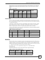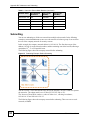
1
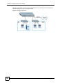
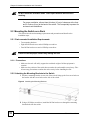
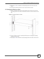
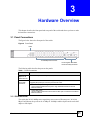
ES-1124
Ethernet Switch
User’s Guide
Version 1.00
10/2006
Edition 2
www.zyxel.com
About This User's Guide
About This User's Guide
Intended Audience
This manual is intended for people who want to install the switch on their network. You
should have at least a basic knowledge of TCP/IP networking concepts and topology.
Related Documentation
• Quick Start Guide
The Quick Start Guide is designed to help you get up and running right away. It contains
information on installing your switch.
• Supporting Disk
Refer to the included CD for support documents.
• ZyXEL Web Site
Please refer to www.zyxel.com for additional support documentation and product
certifications.
User Guide Feedback
Help us help you. Send all User Guide-related comments, questions or suggestions for
improvement to the following address, or use e-mail instead. Thank you!
The Technical Writing Team,
ZyXEL Communications Corp.,
6 Innovation Road II,
Science-Based Industrial Park,
Hsinchu, 300, Taiwan.
E-mail: [email protected]
ES-1124 User’s Guide
3
Document Conventions
Document Conventions
Warnings and Notes
These are how warnings and notes are shown in this User’s Guide.
1
"
Warnings tell you about things that could harm you or your device.
Notes tell you other important information (for example, other things you may
need to configure or helpful tips) or recommendations.
Syntax Conventions
• The ES-1124 may be referred to as the “switch”, the “device” or the “system” in this
User’s Guide.
• Product labels are all in bold font.
• Units of measurement may denote the “metric” value or the “scientific” value. For
example, “k” for kilo may denote “1000” or “1024”, “M” for mega may denote “1000000”
or “1048576” and so on.
• “e.g.,” is a shorthand for “for instance”, and “i.e.,” means “that is” or “in other words”.
Icons Used in Figures
Figures in this User’s Guide may use the following generic icons. The ES-1124 icon is not an
exact representation of your device.
4
the ES-1124
Computer
Server
Printer
Switch
Internetl
ES-1124 User’s Guide
Safety Warnings
Safety Warnings
1
For your safety, be sure to read and follow all warning notices and instructions.
• Do NOT use this product near water, for example, in a wet basement or near a swimming
pool.
• Do NOT expose your device to dampness, dust or corrosive liquids.
• Do NOT store things on the device.
• Do NOT install, use, or service this device during a thunderstorm. There is a remote risk
of electric shock from lightning.
• Connect ONLY suitable accessories to the device.
• Do NOT open the device or unit. Opening or removing covers can expose you to
dangerous high voltage points or other risks. ONLY qualified service personnel should
service or disassemble this device. Please contact your vendor for further information.
• Make sure to connect the cables to the correct ports.
• Place connecting cables carefully so that no one will step on them or stumble over them.
• Always disconnect all cables from this device before servicing or disassembling.
• Use ONLY an appropriate power adaptor or cord for your device.
• Connect the power adaptor or cord to the right supply voltage (for example, 110V AC in
North America or 230V AC in Europe).
• Do NOT allow anything to rest on the power adaptor or cord and do NOT place the
product where anyone can walk on the power adaptor or cord.
• Do NOT use the device if the power adaptor or cord is damaged as it might cause
electrocution.
• If the power adaptor or cord is damaged, remove it from the power outlet.
• Do NOT attempt to repair the power adaptor or cord. Contact your local vendor to order a
new one.
• Do not use the device outside, and make sure all the connections are indoors. There is a
remote risk of electric shock from lightning.
• Do NOT obstruct the device ventilation slots, as insufficient airflow may harm your
device.
ES-1124 User’s Guide
5
Safety Warnings
This product is recyclable. Dispose of it properly.
6
ES-1124 User’s Guide
Table of Contents
Table of Contents
About This User's Guide .......................................................................................................... 3
Document Conventions............................................................................................................ 4
Safety Warnings........................................................................................................................ 5
Table of Contents...................................................................................................................... 7
List of Figures ........................................................................................................................... 9
List of Tables........................................................................................................................... 11
Part I: Introduction, Hardware Installation and Troubleshooting ...... 13
Chapter 1
Getting to Know Your Switch................................................................................................. 15
1.1 Introduction .......................................................................................................................... 15
1.1.1 Backbone Application ................................................................................................. 15
1.1.2 Bridging Example ....................................................................................................... 15
Chapter 2
Hardware Installation and Connection ................................................................................. 17
2.1 Freestanding Installation ..................................................................................................... 17
2.2 Mounting the Switch on a Rack .......................................................................................... 18
2.2.1 Rack-mounted Installation Requirements .................................................................. 18
2.2.2 Attaching the Mounting Brackets to the Switch .......................................................... 18
2.2.3 Mounting the Switch on a Rack .................................................................................. 19
Chapter 3
Hardware Overview................................................................................................................. 21
3.1 Panel Connections ............................................................................................................. 21
3.1.1 Ethernet Ports ............................................................................................................ 21
3.1.2 Dual Personality GbE Interfaces ................................................................................ 22
3.1.3 Mini-GBIC Slots ......................................................................................................... 22
3.2 Rear Panel ........................................................................................................................... 24
3.2.1 Power Connector ....................................................................................................... 24
3.3 LEDs
................................................................................................................................ 24
ES-1124 User’s Guide
7
Table of Contents
Chapter 4
Troubleshooting...................................................................................................................... 25
Part II: Appendices and Index............................................................... 27
Appendix A Product Specifications ................................................................................... 29
Appendix B IP Addresses and Subnetting ........................................................................ 31
Appendix C Legal Information........................................................................................... 39
Appendix D Customer Support ......................................................................................... 43
Index......................................................................................................................................... 47
8
ES-1124 User’s Guide
List of Figures
List of Figures
Figure 1 Backbone Application .............................................................................................................. 15
Figure 2 Bridging Application ................................................................................................................ 16
Figure 3 Attaching Rubber Feet ............................................................................................................ 17
Figure 4 Attaching the Mounting Brackets ............................................................................................. 18
Figure 5 Mounting the Switch on a Rack .............................................................................................. 19
Figure 6 Front Panel ............................................................................................................................. 21
Figure 7 Transceiver Installation Example ............................................................................................. 23
Figure 8 Installed Transceiver
.............................................................................................................. 23
Figure 9 Opening the Transceiver’s Latch Example .............................................................................. 23
Figure 10 Transceiver Removal Example .............................................................................................. 23
Figure 11 Rear Panel ............................................................................................................................. 24
Figure 12 Network Number and Host ID ................................................................................................ 32
Figure 13 Subnetting Example: Before Subnetting ................................................................................ 34
Figure 14 Subnetting Example: After Subnetting ................................................................................... 35
ES-1124 User’s Guide
9
List of Figures
10
ES-1124 User’s Guide
List of Tables
List of Tables
Table 1 Panel Connections .................................................................................................................... 21
Table 2 LEDs ......................................................................................................................................... 24
Table 3 Hardware Specifications ........................................................................................................... 29
Table 4 Firmware Specifications ............................................................................................................ 29
Table 5 .................................................................................................................................................. 32
Table 6 Subnet Masks ........................................................................................................................... 33
Table 7 Maximum Host Numbers .......................................................................................................... 33
Table 8 Alternative Subnet Mask Notation ............................................................................................. 33
Table 9 Subnet 1 .................................................................................................................................... 35
Table 10 Subnet 2 .................................................................................................................................. 36
Table 11 Subnet 3 .................................................................................................................................. 36
Table 12 Subnet 4 .................................................................................................................................. 36
Table 13 Eight Subnets .......................................................................................................................... 36
Table 14 24-bit Network Number Subnet Planning ................................................................................ 37
Table 15 16-bit Network Number Subnet Planning ................................................................................ 37
ES-1124 User’s Guide
11
List of Tables
12
ES-1124 User’s Guide
P ART I
Introduction,
Hardware
Installation and
Troubleshooting
This part contains the following:
Getting to Know Your Switch (15)
Hardware Installation and Connection (17)
Hardware Overview (21)
Troubleshooting (25)
13
14
CHAPTER
1
Getting to Know Your Switch
This chapter introduces the main features and applications of the switch.
1.1 Introduction
The ES-1124 is an Ethernet switch with 24 10/100Mbps ports and 2 GbE dual personality
interfaces for uplink. A dual personality interface includes one Gigabit port and one slot for a
mini-GBIC transceiver (SFP module) with one port active at a time.
See Appendix A on page 29 for a full list of features available on the switch.
1.1.1 Backbone Application
The switch is an ideal solution for small networks where rapid growth can be expected in the
near future. The switch can be used standalone for a group of heavy traffic users. You can
connect computers and servers directly to the switch’s port or connect other switches to the
switch.
In this example, all computers can share high-speed applications on the server. To expand the
network, simply add more networking devices such as switches, routers, computers, print
servers etc.
Figure 1 Backbone Application
1.1.2 Bridging Example
In this example application the switch connects different company departments (RD and
Sales) to the corporate backbone. It can alleviate bandwidth contention and eliminate server
and network bottlenecks. All users that need high bandwidth can connect to high-speed
department servers via the switch. You can provide a super-fast uplink connection by using a
Gigabit Ethernet/mini-GBIC port on the switch.
ES-1124 User’s Guide
15
Chapter 1 Getting to Know Your Switch
Moreover, the switch eases supervision and maintenance by allowing network managers to
centralize multiple servers at a single location.
Figure 2 Bridging Application
16
ES-1124 User’s Guide
CHAPTER
2
Hardware Installation and
Connection
This chapter shows you how to install and connect the switch.
2.1 Freestanding Installation
1 Make sure the switch is clean and dry.
2 Set the switch on a smooth, level surface strong enough to support the weight of the
switch and the connected cables. Make sure there is a power outlet nearby.
3 Make sure there is enough clearance around the switch to allow air circulation and the
attachment of cables and the power cord.
4 Remove the adhesive backing from the rubber feet.
5 Attach the rubber feet to each corner on the bottom of the switch. These rubber feet help
protect the switch from shock or vibration and ensure space between devices when
stacking.
Figure 3 Attaching Rubber Feet
ES-1124 User’s Guide
17
Chapter 2 Hardware Installation and Connection
"
Do NOT block the ventilation holes. Leave space between devices when
stacking.
For proper ventilation, allow at least 4 inches (10 cm) of clearance at the front
and 3.4 inches (8 cm) at the back of the switch. This is especially important for
enclosed rack installations.
2.2 Mounting the Switch on a Rack
This section lists the rack mounting requirements and precautions and describes the
installation steps.
2.2.1 Rack-mounted Installation Requirements
• Two mounting brackets.
• Eight M3 flat head screws and a #2 Philips screwdriver.
• Four M5 flat head screws and a #2 Philips screwdriver.
"
Failure to use the proper screws may damage the unit.
2.2.1.1 Precautions
• Make sure the rack will safely support the combined weight of all the equipment it
contains.
• Make sure the position of the switch does not make the rack unstable or top-heavy. Take
all necessary precautions to anchor the rack securely before installing the unit.
2.2.2 Attaching the Mounting Brackets to the Switch
1 Position a mounting bracket on one side of the switch, lining up the four screw holes on
the bracket with the screw holes on the side of the switch.
Figure 4 Attaching the Mounting Brackets
2 Using a #2 Philips screwdriver, install the M3 flat head screws through the mounting
bracket holes into the switch.
18
ES-1124 User’s Guide
Chapter 2 Hardware Installation and Connection
3 Repeat steps 1 and 2 to install the second mounting bracket on the other side of the
switch.
4 You may now mount the switch on a rack. Proceed to the next section.
2.2.3 Mounting the Switch on a Rack
1 Position a mounting bracket (that is already attached to the switch) on one side of the
rack, lining up the two screw holes on the bracket with the screw holes on the side of the
rack.
Figure 5 Mounting the Switch on a Rack
2 Using a #2 Philips screwdriver, install the M5 flat head screws through the mounting
bracket holes into the rack.
3 Repeat steps 1 and 2 to attach the second mounting bracket on the other side of the rack.
ES-1124 User’s Guide
19
Chapter 2 Hardware Installation and Connection
20
ES-1124 User’s Guide
CHAPTER
3
Hardware Overview
This chapter describes the front panel and rear panel of the switch and shows you how to make
the hardware connections.
3.1 Panel Connections
The figure below shows the front panel of the switch.
Figure 6 Front Panel
LEDs
10/100 Mbps Ethernet Ports
RJ-45 Gigabit / Mini-GBIC
Dual Personality Interfaces
The following table describes the ports on the panels.
Table 1 Panel Connections
CONNECTOR
DESCRIPTION
24 10/100
Mbps RJ-45
Ethernet Ports
Connect these ports to a computer, a hub, an Ethernet switch or router.
Two Dual
Personality
Interfaces
Each interface has one 1000 Base-T copper RJ-45 port and one Small Form-Factor
Pluggable (SFP) fiber port, with one port active at a time.
•
2 100/1000 Mbps RJ-45 Gigabit Ports:
Connect these Gigabit Ethernet ports to high-bandwidth backbone network
Ethernet switches.
•
2 Mini-GBIC Ports:
Use mini-GBIC transceivers in these slots for fiber-optic connections to backbone
Ethernet switches.
3.1.1 Ethernet Ports
The switch has 24 10/100Mbps auto-negotiating, auto-crossover Ethernet ports. In 10/100
Mbps Fast Ethernet, the speed can be 10 Mbps or 100 Mbps and the duplex mode can be half
duplex or full duplex.
ES-1124 User’s Guide
21
Chapter 3 Hardware Overview
An auto-negotiating port can detect and adjust to the optimum Ethernet speed (100/
1000Mpbs) and duplex mode (full duplex or half duplex) of the connected device.
An auto-crossover (auto-MDI/MDI-X) port automatically works with a straight-through or
crossover Ethernet cable.
3.1.1.1 Default Ethernet Settings
The factory default negotiation settings for the Ethernet ports on the switch are:
• Speed: Auto
• Duplex: Auto
• Flow control: Off
3.1.2 Dual Personality GbE Interfaces
There are two Dual Personality GbE interfaces (Gigabit Ethernet/mini-GBIC ports). The miniGBIC ports have priority over the Gigabit ports. This means that if a mini-GBIC port and the
corresponding Gigabit port are connected at the same time, the Gigabit port will be disabled.
The speed of the Gigabit Ethernet/mini-GBIC ports can be 100Mbps or 1000Mbps and the
duplex mode can be half duplex (at 100 Mbps) or full duplex.
3.1.3 Mini-GBIC Slots
These are slots for mini-GBIC (Gigabit Interface Converter) transceivers. A transceiver is a
single unit that houses a transmitter and a receiver. The switch does not come with
transceivers. You must use transceivers that comply with the SFP Transceiver MultiSource
Agreement (MSA). See the SFF committee’s INF-8074i specification Rev 1.0 for details.
There are two pairs of Gigabit Ethernet/mini-GBIC ports. The mini-GBIC ports have priority
over the Gigabit ports. This means that if a mini-GBIC port and the corresponding Gigabit port
are connected at the same time, the Gigabit port will be disabled.
You can change transceivers while the switch is operating. You can use different transceivers
to connect to Ethernet switches with different types of fiber-optic connectors.
• Type: SFP connection interface
• Connection speed: 1 Gigabit per second (Gbps)
"
To avoid possible eye injury, do not look into an operating fiber-optic module’s
connectors.
3.1.3.1 Transceiver Installation
Use the following steps to install a mini GBIC transceiver (SFP module).
1 Insert the transceiver into the slot with the exposed section of PCB board facing down.
22
ES-1124 User’s Guide
Chapter 3 Hardware Overview
Figure 7 Transceiver Installation Example
2 Press the transceiver firmly until it clicks into place.
3 The switch automatically detects the installed transceiver. Check the LEDs to verify that
it is functioning properly.
Figure 8 Installed Transceiver
3.1.3.2 Transceiver Removal
Use the following steps to remove a mini GBIC transceiver (SFP module).
1 Open the transceiver’s latch (latch styles vary).
Figure 9 Opening the Transceiver’s Latch Example
2 Pull the transceiver out of the slot.
Figure 10 Transceiver Removal Example
ES-1124 User’s Guide
23
Chapter 3 Hardware Overview
3.2 Rear Panel
The following figure shows the rear panel of the switche.
Figure 11 Rear Panel
3.2.1 Power Connector
Make sure you are using the correct power source as shown on the panel.
To connect the power to the ES-1124 AC unit, insert the female end of power cord to the
power receptacle on the rear panel. Connect the other end of the supplied power cord to a
100~240V AC, 1.5A power outlet. Make sure that no objects obstruct the airflow of the fans.
3.3 LEDs
The following table describes the LEDs.
Table 2 LEDs
LED
COLOR
STATUS
DESCRIPTION
PWR
Green
On
The system is turned on.
Off
The system is off.
Blinking
The system is transmitting/receiving to/from an Ethernet network.
On
The link to an Ethernet network is up.
Off
The link to an Ethernet network is down.
On
The port has a successful 1000 Mbps connection to a network.
Blinking
The port is receiving or transmitting data to/from a 1000 Mbps
network.
Off
The port is not connected to a 1000 network or the link is down.
On
The port has a successful connection to a 100 Mbps Ethernet
network.
Blinking
The port is receiving or transmitting data to/from a 100 Mbps
Ethernet network.
Off
The port is not connected to a 100 Ethernet device or the link is
down.
On
The port has a successful connection to a 10 Mbps Ethernet
network.
Blinking
The port is receiving or transmitting data to/from a 10 Mbps
Ethernet network.
Off
The port is not connected to a 10 Ethernet device or the link is
down.
Ethernet Ports
LNK/ACT
Green
Gigabit/Mini-GBIC Port
1000
100
10
24
Green
Green
Green
ES-1124 User’s Guide
CHAPTER
4
Troubleshooting
This chapter offers some suggestions to solve problems you might encounter.
V
The switch does not turn on. None of the LEDs turn on.
1 Make sure you are using the power adaptor or cord included with the switch.
2 Make sure the power adaptor or cord is connected to the switch and plugged in to an
appropriate power source. Make sure the power source is turned on.
3 Turn the switch off and on.
4 Disconnect and re-connect the power adaptor or cord to the switch.
5 If the problem continues, contact the vendor.
V
One of the LEDs does not behave as expected.
1
2
3
4
5
Make sure you understand the normal behavior of the LED. See Section 3.3 on page 24.
Check the hardware connections. See Section 3.1 on page 21.
Inspect your cables for damage. Contact the vendor to replace any damaged cables.
Disconnect and re-connect the power adaptor to the switch.
If the problem continues, contact the vendor.
ES-1124 User’s Guide
25
Chapter 4 Troubleshooting
26
ES-1124 User’s Guide
P ART II
Appendices and
Index
This part contains the following:
Product Specifications (29)
IP Addresses and Subnetting (31)
Legal Information (39)
Index (47)
27
28
APPENDIX
A
Product Specifications
The following tables summarize the switch’s hardware and firmware features.
Table 3 Hardware Specifications
LEDs
PWR
Per Gigabit port: 1000, LNK/ACT
Per mini-GBIC port: LNK, ACT
Per Ethernet port: LNK, ACT
Dimensions (W x D x H)
441 x 130 x 44 mm
19” rack mountable
Power Supply
100 - 240 VAC 50/60Hz internal universal power supply
Power Consumption
19.8 Watt Max.
Interfaces
24 10/100 Ethernet RJ-45 ports
2 GbE Dual Personality interfaces (Each interface has one 1000Base-T
copper port and one Small Form-Factor Pluggable (SFP) fiber port, with one
port active at a time.)
Auto-negotiation
Auto-MDIX
Compliant with IEEE 802.3ad/u/x
Back pressure flow control for half duplex
Flow control for full duplex (IEEE 802.3x)
Operation Temperature
0º C ~ 45º C
Operation Humidity
10% ~ 90% RH
Table 4 Firmware Specifications
FEATURE
DESCRIPTION
Data Buffer
320 K
Layer 2 Features
Bridging: 8K MAC addresses
Switching: Switching fabric: 8.8 Gbps, non-blocking
Max. Frame size: 1522 bytes
IEEE 802.1p support for two outgoing priority queues
Broadcast Storm Control
Supports automatic address learning
Store-and-forwarding switching architecture for abnormal packet filtering
Other Features
No-Blocking full wire speed architecture
Fanless design
EMC
FCC Part 15 (Class A)
CE EMC (Class A)
ES-1124 User’s Guide
29
Appendix A Product Specifications
30
ES-1124 User’s Guide
APPENDIX
B
IP Addresses and Subnetting
This appendix introduces IP addresses and subnet masks.
IP addresses identify individual devices on a network. Every networking device (including
computers, servers, routers, printers, etc.) needs an IP address to communicate across the
network. These networking devices are also known as hosts.
Subnet masks determine the maximum number of possible hosts on a network. You can also
use subnet masks to divide one network into multiple sub-networks.
Introduction to IP Addresses
One part of the IP address is the network number, and the other part is the host ID. In the same
way that houses on a street share a common street name, the hosts on a network share a
common network number. Similarly, as each house has its own house number, each host on
the network has its own unique identifying number - the host ID. Routers use the network
number to send packets to the correct network, while the host ID determines to which host on
the network the packets are delivered.
Structure
An IP address is made up of four parts, written in dotted decimal notation (for example,
192.168.1.1). Each of these four parts is known as an octet. An octet is an eight-digit binary
number (for example 11000000, which is 192 in decimal notation).
Therefore, each octet has a possible range of 00000000 to 11111111 in binary, or 0 to 255 in
decimal.
The following figure shows an example IP address in which the first three octets (192.168.1)
are the network number, and the fourth octet (16) is the host ID.
ES-1124 User’s Guide
31
Appendix B IP Addresses and Subnetting
Figure 12 Network Number and Host ID
How much of the IP address is the network number and how much is the host ID varies
according to the subnet mask.
Subnet Masks
A subnet mask is used to determine which bits are part of the network number, and which bits
are part of the host ID (using a logical AND operation). The term “subnet” is short for “subnetwork”.
A subnet mask has 32 bits. If a bit in the subnet mask is a “1” then the corresponding bit in the
IP address is part of the network number. If a bit in the subnet mask is “0” then the
corresponding bit in the IP address is part of the host ID.
The following example shows a subnet mask identifying the network number (in bold text)
and host ID of an IP address (192.168.1.2 in decimal).
Table 5
1ST
OCTET:
(192)
2ND
OCTET:
(168)
3RD
OCTET:
(1)
4TH OCTET
(2)
IP Address (Binary)
11000000
10101000
00000001
00000010
Subnet Mask (Binary)
11111111
11111111
11111111
00000000
Network Number
11000000
10101000
00000001
Host ID
00000010
By convention, subnet masks always consist of a continuous sequence of ones beginning from
the leftmost bit of the mask, followed by a continuous sequence of zeros, for a total number of
32 bits.
Subnet masks can be referred to by the size of the network number part (the bits with a “1”
value). For example, an “8-bit mask” means that the first 8 bits of the mask are ones and the
remaining 24 bits are zeroes.
32
ES-1124 User’s Guide
Appendix B IP Addresses and Subnetting
Subnet masks are expressed in dotted decimal notation just like IP addresses. The following
examples show the binary and decimal notation for 8-bit, 16-bit, 24-bit and 29-bit subnet
masks.
Table 6 Subnet Masks
BINARY
DECIMAL
1ST
OCTET
2ND
OCTET
3RD
OCTET
4TH OCTET
8-bit mask
11111111
00000000
00000000
00000000
255.0.0.0
16-bit mask
11111111
11111111
00000000
00000000
255.255.0.0
24-bit mask
11111111
11111111
11111111
00000000
255.255.255.0
29-bit mask
11111111
11111111
11111111
11111000
255.255.255.248
Network Size
The size of the network number determines the maximum number of possible hosts you can
have on your network. The larger the number of network number bits, the smaller the number
of remaining host ID bits.
An IP address with host IDs of all zeros is the IP address of the network (192.168.1.0 with a
24-bit subnet mask, for example). An IP address with host IDs of all ones is the broadcast
address for that network (192.168.1.255 with a 24-bit subnet mask, for example).
As these two IP addresses cannot be used for individual hosts, calculate the maximum number
of possible hosts in a network as follows:
Table 7 Maximum Host Numbers
SUBNET MASK
8 bits
HOST ID SIZE
255.0.0.0
MAXIMUM NUMBER OF HOSTS
24 bits
224
–2
16777214
–2
65534
16 bits
255.255.0.0
16 bits
216
24 bits
255.255.255.0
8 bits
28 – 2
254
3 bits
23
6
29 bits
255.255.255.248
–2
Notation
Since the mask is always a continuous number of ones beginning from the left, followed by a
continuous number of zeros for the remainder of the 32 bit mask, you can simply specify the
number of ones instead of writing the value of each octet. This is usually specified by writing
a “/” followed by the number of bits in the mask after the address.
For example, 192.1.1.0 /25 is equivalent to saying 192.1.1.0 with subnet mask
255.255.255.128.
The following table shows some possible subnet masks using both notations.
Table 8 Alternative Subnet Mask Notation
SUBNET MASK
ALTERNATIVE
NOTATION
LAST OCTET
(BINARY)
LAST OCTET
(DECIMAL)
255.255.255.0
/24
0000 0000
0
255.255.255.128
/25
1000 0000
128
ES-1124 User’s Guide
33
Appendix B IP Addresses and Subnetting
Table 8 Alternative Subnet Mask Notation (continued)
SUBNET MASK
ALTERNATIVE
NOTATION
LAST OCTET
(BINARY)
LAST OCTET
(DECIMAL)
255.255.255.192
/26
1100 0000
192
255.255.255.224
/27
1110 0000
224
255.255.255.240
/28
1111 0000
240
255.255.255.248
/29
1111 1000
248
255.255.255.252
/30
1111 1100
252
Subnetting
You can use subnetting to divide one network into multiple sub-networks. In the following
example a network administrator creates two sub-networks to isolate a group of servers from
the rest of the company network for security reasons.
In this example, the company network address is 192.168.1.0. The first three octets of the
address (192.168.1) are the network number, and the remaining octet is the host ID, allowing a
maximum of 28 – 2 or 254 possible hosts.
The following figure shows the company network before subnetting.
Figure 13 Subnetting Example: Before Subnetting
You can “borrow” one of the host ID bits to divide the network 192.168.1.0 into two separate
sub-networks. The subnet mask is now 25 bits (255.255.255.128 or /25).
The “borrowed” host ID bit can have a value of either 0 or 1, allowing two subnets;
192.168.1.0 /25 and 192.168.1.128 /25.
The following figure shows the company network after subnetting. There are now two subnetworks, A and B.
34
ES-1124 User’s Guide
Appendix B IP Addresses and Subnetting
Figure 14 Subnetting Example: After Subnetting
In a 25-bit subnet the host ID has 7 bits, so each sub-network has a maximum of 27 – 2 or 126
possible hosts (a host ID of all zeroes is the subnet’s address itself, all ones is the subnet’s
broadcast address).
192.168.1.0 with mask 255.255.255.128 is subnet A itself, and 192.168.1.127 with mask
255.255.255.128 is its broadcast address. Therefore, the lowest IP address that can be assigned
to an actual host for subnet A is 192.168.1.1 and the highest is 192.168.1.126.
Similarly, the host ID range for subnet B is 192.168.1.129 to 192.168.1.254.
Example: Four Subnets
The previous example illustrated using a 25-bit subnet mask to divide a 24-bit address into two
subnets. Similarly, to divide a 24-bit address into four subnets, you need to “borrow” two host
ID bits to give four possible combinations (00, 01, 10 and 11). The subnet mask is 26 bits
(11111111.11111111.11111111.11000000) or 255.255.255.192.
Each subnet contains 6 host ID bits, giving 26 - 2 or 62 hosts for each subnet (a host ID of all
zeroes is the subnet itself, all ones is the subnet’s broadcast address).
Table 9 Subnet 1
IP/SUBNET MASK
NETWORK NUMBER
LAST OCTET BIT
VALUE
IP Address (Decimal)
192.168.1.
0
IP Address (Binary)
11000000.10101000.00000001.
00000000
Subnet Mask (Binary)
11111111.11111111.11111111.
11000000
Subnet Address:
192.168.1.0
Lowest Host ID: 192.168.1.1
Broadcast Address:
192.168.1.63
Highest Host ID: 192.168.1.62
ES-1124 User’s Guide
35
Appendix B IP Addresses and Subnetting
Table 10 Subnet 2
IP/SUBNET MASK
NETWORK NUMBER
LAST OCTET BIT
VALUE
IP Address
192.168.1.
64
IP Address (Binary)
11000000.10101000.00000001.
01000000
Subnet Mask (Binary)
11111111.11111111.11111111.
11000000
Subnet Address:
192.168.1.64
Lowest Host ID: 192.168.1.65
Broadcast Address:
192.168.1.127
Highest Host ID: 192.168.1.126
Table 11 Subnet 3
IP/SUBNET MASK
NETWORK NUMBER
LAST OCTET BIT
VALUE
IP Address
192.168.1.
128
IP Address (Binary)
11000000.10101000.00000001.
10000000
Subnet Mask (Binary)
11111111.11111111.11111111.
11000000
Subnet Address:
192.168.1.128
Lowest Host ID: 192.168.1.129
Broadcast Address:
192.168.1.191
Highest Host ID: 192.168.1.190
Table 12 Subnet 4
IP/SUBNET MASK
NETWORK NUMBER
LAST OCTET BIT
VALUE
IP Address
192.168.1.
192
IP Address (Binary)
11000000.10101000.00000001.
11000000
Subnet Mask (Binary)
11111111.11111111.11111111.
11000000
Subnet Address:
192.168.1.192
Lowest Host ID: 192.168.1.193
Broadcast Address:
192.168.1.255
Highest Host ID: 192.168.1.254
Example: Eight Subnets
Similarly, use a 27-bit mask to create eight subnets (000, 001, 010, 011, 100, 101, 110 and
111).
The following table shows IP address last octet values for each subnet.
Table 13 Eight Subnets
36
SUBNET
SUBNET
ADDRESS
FIRST ADDRESS
LAST
ADDRESS
BROADCAST
ADDRESS
1
0
1
30
31
2
32
33
62
63
3
64
65
94
95
4
96
97
126
127
ES-1124 User’s Guide
Appendix B IP Addresses and Subnetting
Table 13 Eight Subnets (continued)
SUBNET
SUBNET
ADDRESS
FIRST ADDRESS
LAST
ADDRESS
BROADCAST
ADDRESS
5
128
129
158
159
6
160
161
190
191
7
192
193
222
223
8
224
225
254
255
Subnet Planning
The following table is a summary for subnet planning on a network with a 24-bit network
number.
Table 14 24-bit Network Number Subnet Planning
NO. “BORROWED”
HOST BITS
SUBNET MASK
NO. SUBNETS
NO. HOSTS PER
SUBNET
1
255.255.255.128 (/25)
2
126
2
255.255.255.192 (/26)
4
62
3
255.255.255.224 (/27)
8
30
4
255.255.255.240 (/28)
16
14
5
255.255.255.248 (/29)
32
6
6
255.255.255.252 (/30)
64
2
7
255.255.255.254 (/31)
128
1
The following table is a summary for subnet planning on a network with a 16-bit network
number.
Table 15 16-bit Network Number Subnet Planning
NO. “BORROWED”
HOST BITS
SUBNET MASK
NO. SUBNETS
NO. HOSTS PER
SUBNET
1
255.255.128.0 (/17)
2
32766
2
255.255.192.0 (/18)
4
16382
3
255.255.224.0 (/19)
8
8190
4
255.255.240.0 (/20)
16
4094
5
255.255.248.0 (/21)
32
2046
6
255.255.252.0 (/22)
64
1022
7
255.255.254.0 (/23)
128
510
8
255.255.255.0 (/24)
256
254
9
255.255.255.128 (/25)
512
126
10
255.255.255.192 (/26)
1024
62
11
255.255.255.224 (/27)
2048
30
12
255.255.255.240 (/28)
4096
14
13
255.255.255.248 (/29)
8192
6
ES-1124 User’s Guide
37
Appendix B IP Addresses and Subnetting
Table 15 16-bit Network Number Subnet Planning (continued)
NO. “BORROWED”
HOST BITS
SUBNET MASK
NO. SUBNETS
NO. HOSTS PER
SUBNET
14
255.255.255.252 (/30)
16384
2
15
255.255.255.254 (/31)
32768
1
Configuring IP Addresses
Where you obtain your network number depends on your particular situation. If the ISP or
your network administrator assigns you a block of registered IP addresses, follow their
instructions in selecting the IP addresses and the subnet mask.
If the ISP did not explicitly give you an IP network number, then most likely you have a single
user account and the ISP will assign you a dynamic IP address when the connection is
established. If this is the case, it is recommended that you select a network number from
192.168.0.0 to 192.168.255.0. The Internet Assigned Number Authority (IANA) reserved this
block of addresses specifically for private use; please do not use any other number unless you
are told otherwise. You must also enable Network Address Translation (NAT) on the switch.
Once you have decided on the network number, pick an IP address for your switch that is easy
to remember (for instance, 192.168.1.1) but make sure that no other device on your network is
using that IP address.
The subnet mask specifies the network number portion of an IP address. Your switch will
compute the subnet mask automatically based on the IP address that you entered. You don't
need to change the subnet mask computed by the switch unless you are instructed to do
otherwise.
Private IP Addresses
Every machine on the Internet must have a unique address. If your networks are isolated from
the Internet (running only between two branch offices, for example) you can assign any IP
addresses to the hosts without problems. However, the Internet Assigned Numbers Authority
(IANA) has reserved the following three blocks of IP addresses specifically for private
networks:
• 10.0.0.0 — 10.255.255.255
• 172.16.0.0 — 172.31.255.255
• 192.168.0.0 — 192.168.255.255
You can obtain your IP address from the IANA, from an ISP, or it can be assigned from a
private network. If you belong to a small organization and your Internet access is through an
ISP, the ISP can provide you with the Internet addresses for your local networks. On the other
hand, if you are part of a much larger organization, you should consult your network
administrator for the appropriate IP addresses.
Regardless of your particular situation, do not create an arbitrary IP address; always
follow the guidelines above. For more information on address assignment, please
refer to RFC 1597, Address Allocation for Private Internets and RFC 1466, Guidelines
for Management of IP Address Space.
38
ES-1124 User’s Guide
APPENDIX
C
Legal Information
Copyright
Copyright © 2006 by ZyXEL Communications Corporation.
The contents of this publication may not be reproduced in any part or as a whole, transcribed,
stored in a retrieval system, translated into any language, or transmitted in any form or by any
means, electronic, mechanical, magnetic, optical, chemical, photocopying, manual, or
otherwise, without the prior written permission of ZyXEL Communications Corporation.
Published by ZyXEL Communications Corporation. All rights reserved.
Disclaimer
ZyXEL does not assume any liability arising out of the application or use of any products, or
software described herein. Neither does it convey any license under its patent rights nor the
patent rights of others. ZyXEL further reserves the right to make changes in any products
described herein without notice. This publication is subject to change without notice.
Trademarks
ZyNOS (ZyXEL Network Operating System) is a registered trademark of ZyXEL
Communications, Inc. Other trademarks mentioned in this publication are used for
identification purposes only and may be properties of their respective owners.
Certifications
Federal Communications Commission (FCC) Interference Statement
This device complies with Part 15 of FCC rules. Operation is subject to the following two
conditions:
• This device may not cause harmful interference.
• This device must accept any interference received, including interference that may cause
undesired operations.
ES-1124 User’s Guide
39
Appendix C Legal Information
FCC Warning
This device has been tested and found to comply with the limits for a Class A digital switch,
pursuant to Part 15 of the FCC Rules. These limits are designed to provide reasonable
protection against harmful interference in a commercial environment. This device generates,
uses, and can radiate radio frequency energy and, if not installed and used in accordance with
the instruction manual, may cause harmful interference to radio communications. Operation of
this device in a residential area is likely to cause harmful interference in which case the user
will be required to correct the interference at his own expense.
CE Mark Warning:
This is a class A product. In a domestic environment this product may cause radio interference
in which case the user may be required to take adequate measures.
Taiwanese BSMI (Bureau of Standards, Metrology and Inspection) A Warning:
Notices
Changes or modifications not expressly approved by the party responsible for compliance
could void the user's authority to operate the equipment.
This Class A digital apparatus complies with Canadian ICES-003.
Cet appareil numérique de la classe A est conforme à la norme NMB-003 du Canada.
CLASS 1 LASER PRODUCT
APPAREIL A LASER DE CLASS 1
PRODUCT COMPLIES WITH 21 CFR 1040.10 AND 1040.11.
PRODUIT CONFORME SELON 21 CFR 1040.10 ET 1040.11.
Viewing Certifications
1 Go to http://www.zyxel.com.
2 Select your product on the ZyXEL home page to go to that product's page.
3 Select the certification you wish to view from this page.
ZyXEL Limited Warranty
ZyXEL warrants to the original end user (purchaser) that this product is free from any defects
in materials or workmanship for a period of up to two years from the date of purchase. During
the warranty period, and upon proof of purchase, should the product have indications of failure
due to faulty workmanship and/or materials, ZyXEL will, at its discretion, repair or replace the
defective products or components without charge for either parts or labor, and to whatever
extent it shall deem necessary to restore the product or components to proper operating
40
ES-1124 User’s Guide
Appendix C Legal Information
condition. Any replacement will consist of a new or re-manufactured functionally equivalent
product of equal or higher value, and will be solely at the discretion of ZyXEL. This warranty
shall not apply if the product has been modified, misused, tampered with, damaged by an act
of God, or subjected to abnormal working conditions.
Note
Repair or replacement, as provided under this warranty, is the exclusive remedy of the
purchaser. This warranty is in lieu of all other warranties, express or implied, including any
implied warranty of merchantability or fitness for a particular use or purpose. ZyXEL shall in
no event be held liable for indirect or consequential damages of any kind to the purchaser.
To obtain the services of this warranty, contact ZyXEL's Service Center for your Return
Material Authorization number (RMA). Products must be returned Postage Prepaid. It is
recommended that the unit be insured when shipped. Any returned products without proof of
purchase or those with an out-dated warranty will be repaired or replaced (at the discretion of
ZyXEL) and the customer will be billed for parts and labor. All repaired or replaced products
will be shipped by ZyXEL to the corresponding return address, Postage Paid. This warranty
gives you specific legal rights, and you may also have other rights that vary from country to
country.
Registration
Register your product online to receive e-mail notices of firmware upgrades and information
at www.zyxel.com for global products, or at www.us.zyxel.com for North American products.
ES-1124 User’s Guide
41
Appendix C Legal Information
42
ES-1124 User’s Guide
APPENDIX
D
Customer Support
Please have the following information ready when you contact customer support.
Required Information
•
•
•
•
Product model and serial number.
Warranty Information.
Date that you received your device.
Brief description of the problem and the steps you took to solve it.
Corporate Headquarters (Worldwide)
•
•
•
•
•
•
•
Support E-mail: [email protected]
Sales E-mail: [email protected]
Telephone: +886-3-578-3942
Fax: +886-3-578-2439
Web Site: www.zyxel.com, www.europe.zyxel.com
FTP Site: ftp.zyxel.com, ftp.europe.zyxel.com
Regular Mail: ZyXEL Communications Corp., 6 Innovation Road II, Science Park,
Hsinchu 300, Taiwan
Costa Rica
•
•
•
•
•
•
•
Support E-mail: [email protected]
Sales E-mail: [email protected]
Telephone: +506-2017878
Fax: +506-2015098
Web Site: www.zyxel.co.cr
FTP Site: ftp.zyxel.co.cr
Regular Mail: ZyXEL Costa Rica, Plaza Roble Escazú, Etapa El Patio, Tercer Piso, San
José, Costa Rica
Czech Republic
•
•
•
•
•
E-mail: [email protected]
Telephone: +420-241-091-350
Fax: +420-241-091-359
Web Site: www.zyxel.cz
Regular Mail: ZyXEL Communications, Czech s.r.o., Modranská 621, 143 01 Praha 4 Modrany, Ceská Republika
ES-1124 User’s Guide
43
Appendix D Customer Support
Denmark
•
•
•
•
•
•
Support E-mail: [email protected]
Sales E-mail: [email protected]
Telephone: +45-39-55-07-00
Fax: +45-39-55-07-07
Web Site: www.zyxel.dk
Regular Mail: ZyXEL Communications A/S, Columbusvej, 2860 Soeborg, Denmark
Finland
•
•
•
•
•
•
Support E-mail: [email protected]
Sales E-mail: [email protected]
Telephone: +358-9-4780-8411
Fax: +358-9-4780 8448
Web Site: www.zyxel.fi
Regular Mail: ZyXEL Communications Oy, Malminkaari 10, 00700 Helsinki, Finland
France
•
•
•
•
•
E-mail: [email protected]
Telephone: +33-4-72-52-97-97
Fax: +33-4-72-52-19-20
Web Site: www.zyxel.fr
Regular Mail: ZyXEL France, 1 rue des Vergers, Bat. 1 / C, 69760 Limonest, France
Germany
•
•
•
•
•
•
Support E-mail: [email protected]
Sales E-mail: [email protected]
Telephone: +49-2405-6909-0
Fax: +49-2405-6909-99
Web Site: www.zyxel.de
Regular Mail: ZyXEL Deutschland GmbH., Adenauerstr. 20/A2 D-52146, Wuerselen,
Germany
Hungary
•
•
•
•
•
•
Support E-mail: [email protected]
Sales E-mail: [email protected]
Telephone: +36-1-3361649
Fax: +36-1-3259100
Web Site: www.zyxel.hu
Regular Mail: ZyXEL Hungary, 48, Zoldlomb Str., H-1025, Budapest, Hungary
Kazakhstan
• Support: http://zyxel.kz/support
• Sales E-mail: [email protected]
44
ES-1124 User’s Guide
Appendix D Customer Support
•
•
•
•
Telephone: +7-3272-590-698
Fax: +7-3272-590-689
Web Site: www.zyxel.kz
Regular Mail: ZyXEL Kazakhstan, 43, Dostyk ave.,Office 414, Dostyk Business Centre,
050010, Almaty, Republic of Kazakhstan
North America
•
•
•
•
•
•
•
Support E-mail: [email protected]
Sales E-mail: [email protected]
Telephone: +1-800-255-4101, +1-714-632-0882
Fax: +1-714-632-0858
Web Site: www.us.zyxel.com
FTP Site: ftp.us.zyxel.com
Regular Mail: ZyXEL Communications Inc., 1130 N. Miller St., Anaheim, CA 928062001, U.S.A.
Norway
•
•
•
•
•
•
Support E-mail: [email protected]
Sales E-mail: [email protected]
Telephone: +47-22-80-61-80
Fax: +47-22-80-61-81
Web Site: www.zyxel.no
Regular Mail: ZyXEL Communications A/S, Nils Hansens vei 13, 0667 Oslo, Norway
Poland
•
•
•
•
•
E-mail: [email protected]
Telephone: +48 (22) 333 8250
Fax: +48 (22) 333 8251
Web Site: www.pl.zyxel.com
Regular Mail: ZyXEL Communications, ul. Okrzei 1A, 03-715 Warszawa, Poland
Russia
•
•
•
•
•
•
Support: http://zyxel.ru/support
Sales E-mail: [email protected]
Telephone: +7-095-542-89-29
Fax: +7-095-542-89-25
Web Site: www.zyxel.ru
Regular Mail: ZyXEL Russia, Ostrovityanova 37a Str., Moscow, 117279, Russia
Spain
•
•
•
•
Support E-mail: [email protected]
Sales E-mail: [email protected]
Telephone: +34-902-195-420
Fax: +34-913-005-345
ES-1124 User’s Guide
45
Appendix D Customer Support
• Web Site: www.zyxel.es
• Regular Mail: ZyXEL Communications, Arte, 21 5ª planta, 28033 Madrid, Spain
Sweden
•
•
•
•
•
•
Support E-mail: [email protected]
Sales E-mail: [email protected]
Telephone: +46-31-744-7700
Fax: +46-31-744-7701
Web Site: www.zyxel.se
Regular Mail: ZyXEL Communications A/S, Sjöporten 4, 41764 Göteborg, Sweden
Ukraine
•
•
•
•
•
•
Support E-mail: [email protected]
Sales E-mail: [email protected]
Telephone: +380-44-247-69-78
Fax: +380-44-494-49-32
Web Site: www.ua.zyxel.com
Regular Mail: ZyXEL Ukraine, 13, Pimonenko Str., Kiev, 04050, Ukraine
United Kingdom
•
•
•
•
•
•
•
Support E-mail: [email protected]
Sales E-mail: [email protected]
Telephone: +44-1344 303044, 08707 555779 (UK only)
Fax: +44-1344 303034
Web Site: www.zyxel.co.uk
FTP Site: ftp.zyxel.co.uk
Regular Mail: ZyXEL Communications UK, Ltd.,11 The Courtyard, Eastern Road,
Bracknell, Berkshire, RG12 2XB, United Kingdom (UK)
“+” is the (prefix) number you dial to make an international telephone call.
46
ES-1124 User’s Guide
Index
Index
A
alternative subnet mask notation 33
applications
backbone 15
bridging 15
C
certifications 39, 40
notices 40
viewing 40
contact information 43
copyright 39
customer support 43
D
dimensions 29
disclaimer 39
hardware overview 21
humidity, operating 29
I
IANA 38
installation
freestanding 17
precautions 18
rack-mounting 18
Internet Assigned Numbers AuthoritySee IANA 38
introduction 15
L
LEDs 24
M
Ethernet ports 21
default settings 22
mini GBIC ports 22
connection speed 22
connector type 22
transceiver installation 22
transceiver removal 23
mounting brackets 18
MSA (MultiSource Agreement) 22
F
N
FCC interference statement 39
front panel 21
NAT 38
E
H
hardware installation 17
mounting 18
ES-1124 User’s Guide
O
operating humidity 29
operating temperature 29
47
Index
P
power specification 29
product registration 41
R
registration
product 41
related documentation 3
rubber feet 17
S
safety warnings 5
status
LED 24
subnet 31
subnet mask 32
subnetting 34
syntax conventions 4
T
temperature, operating 29
trademarks 39
transceiver
installation 22
removal 23
V
ventilation holes 18
W
warranty 40
note 41
48
ES-1124 User’s Guide