1
Manual No.'13•SRK-T-147
RESIDENTIAL AIR-CONDITIONING
TECHNICAL MANUAL & PARTS LIST
WALL MOUNTED TYPE
RESIDENTIAL AIR-CONDITIONERS
(Split system, air to air heat pump type)
SRK63ZMA-S
SRK71ZMA-S
SRK80ZMA-S
SRK92ZMA-S
'13 • SRK-T-147
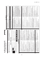
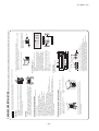
1. SPECIFICATIONS
SRK63ZMA-S
Model
Indoor unit SRK63ZMA-S
Outdoor unit SRC63ZMA-S
Single phase, 220 - 240V, 50Hz
Nominal cooling capacity (range)
kW
6.3 ( 2.15 (Min.) - 7.1 (Max.))
Nominal heating capacity (range)
kW
7.1 ( 1.7 (Min.) - 9.5 (Max.))
Cooling
1.76 ( 0.54 - 2.30 )
Power
consumption
Heating
kW
1.79 ( 0.37 - 3.30 )
Max power consumption
3.65
Cooling
8.3 / 8.0 / 7.6 (220/ 230/ 240 V)
Running
current
Heating
A
8.5 / 8.1 / 7.8 (220/ 230/ 240 V)
Inrush current, max current
8.5 / 8.1 / 7.8 (220/ 230/ 240 V) Max. 17
Operation
Cooling
96
data
Power factor
%
Heating
96
EER
Cooling
3.58
COP
Heating
3.97
Cooling
59
62
Sound power level
Heating
60
63
dB(A)
Cooling
Hi: 47 Me: 43 Lo: 37 ULo: 26
49
Sound pressure level
Heating
Hi: 44 Me: 41 Lo: 36 ULo: 33
50
Silent mode sound pressure level
—
Cooling:45 / Heating:43
Exterior dimensions (Height x Width x Depth)
mm
318 x 1098 x 248
750 x 880(+88) x 340
Exterior appearance
Fine snow
Stucco white
( Munsell color )
( 8.0Y 9.3/0.1 ) near equivalent
( 4.2Y 7.5/1.1 ) near equivalent
Net weight
kg
16
57
Compressor type & Q'ty
—
RMT5118MDE2( Twin rotary type ) x 1
Compressor motor (Starting method)
kW
—
1.40 ( Inverter driven )
—
0.675 (DIAMOND FREEZE MA68)
Refrigerant oil (Amount, type)
Refrigerant (Type, amount, pre-charge length)
kg
R410A 1.8 in outdoor unit (incl. the amount for the piping of 15m )
Heat exchanger
Louver fins & inner grooved tubing
M fins & inner grooved tubing
Refrigerant control
Capillary tubes + Electronic expansion valve
Fan type & Q'ty
Tangential fan x 1
Propeller fan x 1
Fan motor (Starting method)
W
56 x1 (Direct drive)
86 x1 (Direct drive)
Hi: 18.5 Me: 16.0 Lo: 13.0 ULo: 8.0
48.5
Cooling
Air flow
m3/min
Heating
Hi: 20.5 Me: 18.0 Lo: 14.5 ULo: 12.5
43.5
Available external static pressure
Pa
0
0
Outside air intake
Not possible
—
Air filter, Quality / Quantity
Polypropylene net ( washable ) x 2
—
Shock & vibration absorber
Rubber sleeve (for fan motor)
Rubber sleeve (for fan motor & compressor)
Electric heater
—
—
Remote control
Wireless remote control
Operation
Room temperature control
Microcomputer thermostat
control
Operation display
RUN: Green, TIMER: Yellow, HI POWER: Green, ECONO: Orange
Compressor overheat protection, Overcurrent protection,
Safety equipments
Frost protection, Serial signal error protection, Indoor fan motor error protection,
Heating overload protection (High pressure control), Cooling overload protection
Refrigerant piping size (O.D)
mm
Liquid line :φ6.35 (1/4") Gas line :φ15.88 (5/8")
Connecting method
Flare connection
Flare connection
Attached length of piping
m
Liquid line : 0.70 / Gas line : 0.63
—
Installation
Insulation for piping
Necessary (Both sides), independent
data
Refrigerant line (one way) length
m
Max. 30
Vertical height diff. between O.U. and I.U.
m
Max. 20 (Outdoor unit is higher) / Max. 20 (Outdoor unit is lower)
Drain hose
Hose connectable ( VP 16 )
Holes φ20 x 3 pcs
Drain pump, max lift height
mm
—
—
Recommended breaker size
A
20
L.R.A. (Locked rotor ampere)
A
8.5 / 8.1 / 7.8 (220/ 230/ 240 V)
Interconnecting wires
Size x Core number
1.5mm2 x 4 cores (Including earth cable) / Terminal block (Screw fixing type)
IP number
IPX0
IPX4
Mounting kit, Clean filter (Allergen clear filter x 1, Photocatalytic washable deodorizing filter x 1)
Standard accessories
Option parts
Interface kit (SC-BIKN-E)
Item
Power source
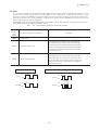
Note (1) The data are measured at the following conditions.
Item
Indoor air temperature
The pipe length is 7.5m.
Outdoor air temperature
DB
WB
DB
WB
Cooling
27˚C
19˚C
35˚C
24˚C
Heating
20˚C
—
7˚C
6˚C
Operation
Standards
ISO5151-T1
(2) This air-conditioner is manufactured and tested in conformity with the ISO.
(3) Sound level indicates the value in an anechoic chamber. During operation these value are somewhat higher
due to ambient conditions.
(4) Select the breaker size according to the own national standard.
(5) This air-conditioner is compliant with DRED (AS/NZS 4755.3.1), and can operate with DRM1,2 or 3,
and is equipped with a terminal block for DRED.
-
4-
RWA000Z251 A
'13 • SRK-T-147
SRK71ZMA-S
Model
Indoor unit SRK71ZMA-S
Outdoor unit SRC71ZMA-S
Single phase, 220 - 240V, 50Hz
Nominal cooling capacity (range)
kW
7.1 ( 2.15 (Min.) - 8.0 (Max.))
Nominal heating capacity (range)
kW
8.0 ( 1.6 (Min.) - 10.0 (Max.))
Cooling
2.16 ( 0.54 - 2.80 )
Power
consumption
Heating
kW
2.14 ( 0.37 - 3.40 )
Max power consumption
3.65
Cooling
10.1 / 9.7 / 9.3 (220/ 230/ 240 V)
Running
current
Heating
A
10.1 / 9.7 / 9.3 (220/ 230/ 240 V)
Inrush current, max current
10.1 / 9.7 / 9.3 (220/ 230/ 240 V) Max. 17
Operation
Cooling
97
data
Power factor
%
Heating
96
EER
Cooling
3.29
COP
Heating
3.74
Cooling
60
66
Sound power level
Heating
61
63
Cooling
dB(A)
Hi: 49 Me: 45 Lo: 39 ULo: 26
53
Sound pressure level
Heating
Hi: 46 Me: 43 Lo: 38 ULo: 35
51
Silent mode sound pressure level
—
Cooling:45 / Heating:44
Exterior dimensions (Height x Width x Depth)
mm
318 x 1098 x 248
750 x 880(+88) x 340
Exterior appearance
Fine snow
Stucco white
( Munsell color )
( 8.0Y 9.3/0.1 ) near equivalent
( 4.2Y 7.5/1.1 ) near equivalent
Net weight
kg
16
57
Compressor type & Q'ty
—
RMT5118MDE2( Twin rotary type ) x 1
Compressor motor (Starting method)
kW
—
1.40 ( Inverter driven )
Refrigerant oil (Amount, type)
—
0.675 (DIAMOND FREEZE MA68)
Refrigerant (Type, amount, pre-charge length)
kg
R410A 1.8 in outdoor unit (incl. the amount for the piping of 15m )
Heat exchanger
Louver fins & inner grooved tubing
M fins & inner grooved tubing
Refrigerant control
Capillary tubes + Electronic expansion valve
Fan type & Q'ty
Tangential fan x 1
Propeller fan x 1
Fan motor (Starting method)
W
56 x1 (Direct drive)
86 x1 (Direct drive)
Cooling
Hi: 19.5 Me: 17.5 Lo: 14.0 ULo: 8.0
55.0
Air flow
m3/min
Heating
Hi: 21.5 Me: 19.5 Lo: 15.5 ULo: 14.0
43.5
Available external static pressure
Pa
0
0
Outside air intake
Not possible
—
Air filter, Quality / Quantity
Polypropylene net ( washable ) x 2
—
Shock & vibration absorber
Rubber sleeve (for fan motor)
Rubber sleeve (for fan motor & compressor)
Electric heater
—
—
Remote control
Wireless remote control
Operation
Room temperature control
Microcomputer thermostat
control
Operation display
RUN: Green, TIMER: Yellow, HI POWER: Green, ECONO: Orange
Compressor overheat protection, Overcurrent protection,
Safety equipments
Frost protection, Serial signal error protection, Indoor fan motor error protection,
Heating overload protection (High pressure control), Cooling overload protection
Refrigerant piping size (O.D)
mm
Liquid line :φ6.35 (1/4") Gas line :φ15.88 (5/8")
Connecting method
Flare connection
Flare connection
Attached length of piping
m
Liquid line : 0.70 / Gas line : 0.63
—
Installation
Insulation for piping
Necessary (Both sides), independent
data
Refrigerant line (one way) length
m
Max. 30
Vertical height diff. between O.U. and I.U.
m
Max. 20 (Outdoor unit is higher) / Max. 20 (Outdoor unit is lower)
Drain hose
Hose connectable ( VP 16 )
Holes φ20 x 3 pcs
Drain pump, max lift height
mm
—
—
Recommended breaker size
A
20
L.R.A. (Locked rotor ampere)
A
10.1 / 9.7 / 9.3 (220/ 230/ 240 V)
Interconnecting wires
Size x Core number
1.5mm2 x 4 cores (Including earth cable) / Terminal block (Screw fixing type)
IP number
IPX0
IPX4
Mounting kit, Clean filter (Allergen clear filter x 1, Photocatalytic washable deodorizing filter x 1)
Standard accessories
Option parts
Interface kit (SC-BIKN-E)
Item
Power source
Note (1) The data are measured at the following conditions.
Item
Indoor air temperature
The pipe length is 7.5m.
Outdoor air temperature
DB
WB
DB
WB
Cooling
27˚C
19˚C
35˚C
24˚C
Heating
20˚C
—
7˚C
6˚C
Operation
Standards
ISO5151-T1
(2) This air-conditioner is manufactured and tested in conformity with the ISO.
(3) Sound level indicates the value in an anechoic chamber. During operation these value are somewhat higher
due to ambient conditions.
(4) Select the breaker size according to the own national standard.
(5) This air-conditioner is compliant with DRED (AS/NZS 4755.3.1), and can operate with DRM1,2 or 3,
and is equipped with a terminal block for DRED.
-
5-
RWA000Z251 A
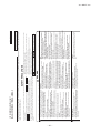
'13 • SRK-T-147
SRK80ZMA-S
Model
Indoor unit SRK80ZMA-S
Outdoor unit SRC80ZMA-S
Single phase, 220 - 240V, 50Hz
Nominal cooling capacity (range)
kW
8.0 ( 2.15 (Min.) - 9.0 (Max.))
Nominal heating capacity (range)
kW
9.0 ( 1.7 (Min.) - 10.5 (Max.))
Cooling
2.35 ( 0.54 - 3.00 )
Power
consumption
Heating
kW
2.57 ( 0.37 - 3.65 )
Max power consumption
3.65
Cooling
11.0 / 10.5 / 10.1 (220/ 230/ 240 V)
Running
current
Heating
A
12.0 / 11.5 / 11.0 (220/ 230/ 240 V)
Inrush current, max current
12.0 / 11.5 / 11.0 (220/ 230/ 240 V) Max. 17
Operation
Cooling
97
data
Power factor
%
Heating
97
EER
Cooling
3.40
COP
Heating
3.50
Cooling
65
69
Sound power level
Heating
63
70
Cooling
dB(A)
Hi: 51 Me: 47 Lo: 41 ULo: 26
56
Sound pressure level
Heating
Hi: 48 Me: 45 Lo: 40 ULo: 37
57
Silent mode sound pressure level
—
Cooling:48 / Heating:50
Exterior dimensions (Height x Width x Depth)
mm
318 x 1098 x 248
845 x 970x 370
Exterior appearance
Fine snow
Stucco white
( Munsell color )
( 8.0Y 9.3/0.1 ) near equivalent
( 4.2Y 7.5/1.1 ) near equivalent
Net weight
kg
16
63
Compressor type & Q'ty
—
RMT5118MDE2( Twin rotary type ) x 1
Compressor motor (Starting method)
kW
—
1.40 ( Inverter driven )
Refrigerant oil (Amount, type)
—
0.675 (DIAMOND FREEZE MA68)
Refrigerant (Type, amount, pre-charge length)
kg
R410A 2.2 in outdoor unit (incl. the amount for the piping of 15m )
Heat exchanger
Louver fins & inner grooved tubing
M fins & inner grooved tubing
Refrigerant control
Capillary tubes + Electronic expansion valve
Fan type & Q'ty
Tangential fan x 1
Propeller fan x 1
Fan motor (Starting method)
W
56 x1 (Direct drive)
86 x1 (Direct drive)
Cooling
Hi: 21.0 Me: 18.5 Lo: 15.0 ULo: 8.0
75.0
Air flow
m3/min
Heating
Hi: 23.5 Me: 20.5 Lo: 17.0 ULo: 15.0
70.0
Available external static pressure
Pa
0
0
Outside air intake
Not possible
—
Air filter, Quality / Quantity
Polypropylene net ( washable ) x 2
—
Shock & vibration absorber
Rubber sleeve (for fan motor)
Rubber sleeve (for fan motor & compressor)
Electric heater
—
—
Remote control
Wireless remote control
Operation
Room temperature control
Microcomputer thermostat
control
Operation display
RUN: Green, TIMER: Yellow, HI POWER: Green, ECONO: Orange
Compressor overheat protection, Overcurrent protection,
Safety equipments
Frost protection, Serial signal error protection, Indoor fan motor error protection,
Heating overload protection (High pressure control), Cooling overload protection
Refrigerant piping size (O.D)
mm
Liquid line :φ6.35 (1/4") Gas line :φ15.88 (5/8")
Connecting method
Flare connection
Flare connection
Attached length of piping
m
Liquid line : 0.70 / Gas line : 0.63
—
Installation
Insulation for piping
Necessary (Both sides), independent
data
Refrigerant line (one way) length
m
Max. 30
Vertical height diff. between O.U. and I.U.
m
Max. 20 (Outdoor unit is higher) / Max. 20 (Outdoor unit is lower)
Drain hose
Hose connectable ( VP 16 )
Holes φ20 x 3 pcs
Drain pump, max lift height
mm
—
—
Recommended breaker size
A
20
L.R.A. (Locked rotor ampere)
A
12.0 / 11.5 / 11.0 (220/ 230/ 240 V)
Interconnecting wires
Size x Core number
1.5mm2 x 4 cores (Including earth cable) / Terminal block (Screw fixing type)
IP number
IPX0
IPX4
Mounting kit, Clean filter (Allergen clear filter x 1, Photocatalytic washable deodorizing filter x 1)
Standard accessories
Option parts
Interface kit (SC-BIKN-E)
Item
Power source
Note (1) The data are measured at the following conditions.
Item
Indoor air temperature
The pipe length is 7.5m.
Outdoor air temperature
DB
WB
DB
WB
Cooling
27˚C
19˚C
35˚C
24˚C
Heating
20˚C
—
7˚C
6˚C
Operation
Standards
ISO5151-T1
(2) This air-conditioner is manufactured and tested in conformity with the ISO.
(3) Sound level indicates the value in an anechoic chamber. During operation these value are somewhat
higher due to ambient conditions.
(4) Select the breaker size according to the own national standard.
(5) This air-conditioner iscompliant with DRED (AS/NZS 4755.3.1), and can operate with DRM1,2 or 3,
and is equipped with a terminal block for DRED.
-
6-
RWA000Z251 A
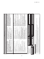
'13 • SRK-T-147
SRK92ZMA-S
Model
Indoor unit SRK92ZMA-S
Outdoor unit SRC92ZMA-S
Single phase, 220 - 240V, 50Hz
Nominal cooling capacity (range)
kW
9.2 ( 2.4 (Min.) - 10.0 (Max.))
Nominal heating capacity (range)
kW
10.0 ( 2.2 (Min.) - 11.2 (Max.))
Cooling
2.54 ( 0.47 - 3.07 )
Power
consumption
Heating
kW
2.84 ( 0.43 - 3.76 )
Max power consumption
3.80
Cooling
11.9 / 11.4 / 10.9 (220/ 230/ 240 V)
Running
current
Heating
A
13.3 / 12.7 / 12.2 (220/ 230/ 240 V)
Inrush current, max current
13.3 / 12.7 / 12.2 (220/ 230/ 240 V) Max. 17.5
Operation
Cooling
97
data
Power factor
%
Heating
97
EER
Cooling
3.62
COP
Heating
3.52
Cooling
65
67
Sound power level
Heating
64
67
dB(A)
Cooling
Hi: 51 Me: 47 Lo: 41 ULo: 26
56
Sound pressure level
Heating
Hi: 49 Me: 46 Lo: 42 ULo: 38
54
Silent mode sound pressure level
—
Cooling:49 / Heating:50
Exterior dimensions (Height x Width x Depth)
mm
318 x 1098 x 248
1300 x 970 x 370
Exterior appearance
Fine snow
Stucco white
( Munsell color )
( 8.0Y 9.3/0.1 ) near equivalent
( 4.2Y 7.5/1.1 ) near equivalent
Net weight
kg
16
92
Compressor type & Q'ty
—
RMT5126MDE1( Twin rotary type ) x 1
Compressor motor (Starting method)
kW
—
4.0 ( Inverter driven )
—
0.9 (DIAMOND FREEZE MA68)
Refrigerant oil (Amount, type)
Refrigerant (Type, amount, pre-charge length)
kg
R410A 3.15 in outdoor unit (incl. the amount for the piping of 15m )
Heat exchanger
Louver fins & inner grooved tubing
M fins & inner grooved tubing
Refrigerant control
Capillary tubes + Electronic expansion valve
Fan type & Q'ty
Tangential fan x 1
Propeller fan x 2
Fan motor (Starting method)
W
56 x1 (Direct drive)
86 x2 (Direct drive)
Hi: 21.0 Me: 18.5 Lo: 15.0 ULo: 8.0
105.0
Cooling
Air flow
m3/min
Heating
Hi: 23.5 Me: 20.5 Lo: 17.0 ULo: 15.0
100.0
Available external static pressure
Pa
0
0
Outside air intake
Not possible
—
Air filter, Quality / Quantity
Polypropylene net ( washable ) x 2
—
Shock & vibration absorber
Rubber sleeve (for fan motor)
Rubber sleeve (for fan motor & compressor)
Electric heater
—
—
Remote control
Wireless remote control
Operation
Room temperature control
Microcomputer thermostat
control
Operation display
RUN: Green, TIMER: Yellow, HI POWER: Green, ECONO: Orange
Compressor overheat protection, Overcurrent protection,
Safety equipments
Frost protection, Serial signal error protection, Indoor fan motor error protection,
Heating overload protection (High pressure control), Cooling overload protection
Refrigerant piping size (O.D)
mm
Liquid line :φ6.35 (1/4") Gas line :φ15.88 (5/8")
Connecting method
Flare connection
Flare connection
Attached length of piping
m
Liquid line : 0.70 / Gas line : 0.63
—
Installation
Insulation for piping
Necessary (Both sides), independent
data
Refrigerant line (one way) length
m
Max. 30
Vertical height diff. between O.U. and I.U.
m
Max. 20 (Outdoor unit is higher) / Max. 20 (Outdoor unit is lower)
Drain hose
Hose connectable ( VP 16 )
Holes φ20 x 3 pcs
Drain pump, max lift height
mm
—
—
Recommended breaker size
A
20
L.R.A. (Locked rotor ampere)
A
13.7 / 12.7 / 12.2 (220/ 230/ 240 V)
Interconnecting wires
Size x Core number
1.5mm2 x 4 cores (Including earth cable) / Terminal block (Screw fixing type)
IP number
IPX0
IPX4
Standard accessories
Mounting kit, Clean filter (Allergen clear filter x 1, Photocatalytic washable deodorizing filter x 1)
Option parts
Interface kit (SC-BIKN-E)
Item
Power source
Note (1) The data are measured at the following conditions.
item
Indoor air temperature
The pipe length is 7.5m.
Outdoor air temperature
DB
WB
DB
WB
Cooling
27˚C
19˚C
35˚C
24˚C
Heating
20˚C
—
7˚C
6˚C
Operation
Standards
ISO5151-T1
(2) This air-conditioner is manufactured and tested in conformity with the ISO.
(3) Sound level indicates the value in an anechoic chamber. During operation these value are somewhat higher
due to ambient conditions.
(4) Select the breaker size according to the own national standard.
(5) This air-conditioner is compliant with DRED (AS/NZS 4755.3.1), and can operate with DRM1,2 or 3,
and is equipped with a terminal block for DRED.
-
7-
RWA000Z251 A
'13 • SRK-T-147
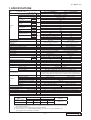
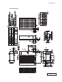
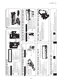
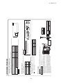
2. EXTERIOR DIMENSIONS
(1) Indoor units
Models SRK63ZMA-S, 71ZMA-S, 80ZMA-S, 92ZMA-S
RKW000Z403
-
8-
'13 • SRK-T-147
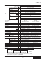
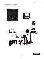
(2) Outdoor units
Models SRC63ZMA-S, 71ZMA-S
RCR000Z008
-
9-
'13 • SRK-T-147
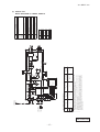
Model SRC80ZMA-S
RCR000Z009
-
10 -
'13 • SRK-T-147
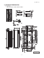
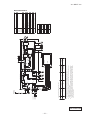
Model SRC92ZMA-S
RCR000Z010
-
11 -
t
t
Th2 1
Th2 2
-
14 -
HEAT
EXCHANGER
SC-BIKN-E
INTERFACE KIT
Th3
t
Th1
DISPLAY
WIRELESS RECEIVER
BACK-UP SW
CNS
CNF
CNG
CNE
BK L
RD J
WH S/N
Y/G G
5
2
8
U
F
250V
3.15A
Va
DS
PRINTED
CIRCUIT
BOARD
HEAT
EXCHANGER
1
3
CNU 4
5
6
CNX2
CNX1
3
2/N
1
RD
BK
WH
Y
BL
T
FMI
M
SM1
LM2
LM1
1
3
POWER WIRES
SIGNAL WIRE
TO OUTDOOR UNIT
Power source
∼220/230/240V 50Hz
M
M
5
5
M
5
2/N
Item
CNE-CNX2
FMI
SM1
LM1,2
Th1
Th2 1,2
Th3
DS
F
T
Va
Color Marks
Mark
Color
BK
Black
BL
Blue
RD
Red
WH White
Y
Yellow
Y/G Yellow/Green
Description
Connector
Fan motor
Flap motor
Louver motor
Room temp. sensor
Heat exch. sensor
Humidity sensor
Diode stack
Fuse
Terminal block
Varistor
'13 • SRK-T-147
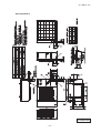
3. ELECTRICAL WIRING
(1) Indoor units
Models SRK63ZMA-S, 71ZMA-S, 80ZMA-S, 92ZMA-S
RWA000Z403
[
3
1 2N
-
15 -
17
2.5
30
CNSUB
CNDRM
1.5mm2 x 4
2
CNTH
R
250V 20A
F8
2
SWITCHING
POWER
CIRCUIT
1.5
Earth wire size
(mm2 )
TH1 TH2 TH3
2
indoor-outdoor
wire size x number
4
CNDRM
(RD) C-2
4(BK)
(WH) S-2
PWB ASSY(DRED)
CNDRED
CNPOWER
MAX power cable length
(m)
(Y/G)
(YE)
(RD)
(BL)
(BK)
(Y/G)
CNMAIN
CN20S
G3
S-1
(WH) S
SO
F1
The specifications shown in the above table are for units without heaters. For units with heaters, refer
to the installation instructions or the construction instructions of the indoor unit.
Switchgear of Circuit breaker capacity which is calculated from MAX. over current should be chosen
along the regulations in each country.
The cable specifications are based on the assumption that a metal or plastic conduit is used with no
more than three cables contained in a conduit and a voltage drop is 2%. For an installation falling
outside of these conditions, please follow the internal cabling regulations. Adapt it to the regulation
in effect in each country.
80
71
63
Power cable size
(mm 2)
20S
(BK)
(WH)
(BR) R OUT
(RD)
(BK) R
RO
250V 3.15A
t゜
Model MAX running current
(A)
(Y/G) G1
(WH) S IN
(BK) R IN
t゜
C
TB3 D1
D2
D3
TERMINAL
BLOCK
(Y/G)
N
3
2
1
(Y/G)
250V 20A
FUSE
PWB ASSY(SUB)
t゜
Power cable, indoor-outdoor connecting wires
SIGNAL WIRE
POWER WIRES
]
TO INDOOR UNIT
TB2
TERMINAL
BLOCK
N
L
(BK)
(WH)
TB1
F10
TERMINAL
BLOCK
250V 10A
(YE)
T1
(OR)
T2
POWER SOURCE
∼220-240V 50Hz
ACTIVE
FILTER
UNIT
+
EEV
M
CNEEV
+
PWB ASSY(MAIN)
+
N
P
W (BK)
V (WH)
U (RD)
CNFAN
W
V
U
POWER
TRANSISTOR
F3 250V 1A
250V 20A
F2
FMo
M
CM
3∼
MS
Fan motor
FMo
Yellow
Yellow/Green
Y/G
RD
White
Orange
Red
OR
YE
Brown
BR
WH
Color
Solenoid valve for 4 way valve
Black
Discharge pipe temp.sensor
20S
Mark
Outdoor air temp.sensor
TH3
BK
Heat exchanger sensor(outdoor unit)
TH2
Terminal block
TH1
TB1,2,3
Reactor
Electric expansion valve(coil)
EEV
R
Connector
CN20S
CNTH
CNEEV
CNFAN
Description
Compressor motor
Item
CM
'13 • SRK-T-147
(2) Outdoor units
Models SRC63ZMA-S, 71ZMA-S, 80ZMA-S
RWC000Z262
[
-
16 -
]
3
1 2N
TB3
D1
D2
D3
C
TERMINAL
BLOCK
(Y/G)
(RD)
N
3
2
TB2
(BK)
1
(WH) S IN
(WH)
17.5
2.5
Power cable size
(mm 2 )
CNFAN0
C-1
M
FMo2
M
FMo1
2
20S
5
5
5
S-1
CNMAIN
CNFAN2
30
CN20V
(BK) R
2
CNSUB
(YE)
(RD)
(BL)
(BK)
(BK)
(WH)
CNFAN
1.5mm2 x 4
F1
T1
T2
1.5
Earth wire size
(mm 2 )
+
+
4
CNDRM
F3 250V 3.15A
SWITCHING
POWER
CIRCUIT
ACTIVE
FILTER
UNIT
CNDRM
250V 20A
F8
PWB ASSY(MAIN)
PWB ASSY(DRED)
CNDRED
CNPOWER
250V 3.15A
(Y/G)
Indoor-outdoor
wire size x number
4
(RD) C-2
4
(WH) S-2
S 0 (WH) S
R0
CN20V
5
2
CNFAN1
F1
MAX power cable length
(m)
CN20S
PWB ASSY(SUB)
250V 1A
The specifications shown in the above table are for units without heaters. For units with heaters, refer
to the installation instructions or the construction instructions of the indoor unit.
Switchgear of Circuit breaker capacity which is calculated from MAX. over current should be chosen
along the regulations in each country.
The cable specifications are based on the assumption that a metal or plastic conduit is used with no
more than three cables contained in a conduit and a voltage drop is 2%. For an installation falling
outside of these conditions, please follow the internal cabling regulations. Adapt it to the regulation
in effect in each country.
92
Model MAX running current
(A)
CNA
(Y/G) G1
(Y/G) G3
Power cable, indoor-outdoor connecting wires
SIGNAL WIRE
POWER WIRES
TO INDOOR UNIT
(BK)
(Y/G)
TERMINAL
BLOCK
TB1
L
N
250V 20A
(BK) R IN
F2
FUSE
250V 1A
TERMINAL
BLOCK
+
TH2
TH3
TH4
2
2
N
P
EEV
M
5
CNEEV
W
V
U
POWER
TRANSISTOR
2
CNTH
250V 20A
F2
t゜
R
t゜
(YE)
(OR)
t゜
POWER SOURCE
∼220-240V 50Hz
U (RD)
W (BK)
V (WH)
CM
3∼
MS
Solenoid valve for 4 way valve
Orange
Yellow
Blue
Yellow/Green
BL
Y/G
White
Red
YE
WH
RD
OR
Brown
Discharge pipe temp.sensor
20S
Black
Outdoor air temp.sensor
TH4
BR
Heat exchanger sensor(outdoor unit)
TH3
Color
Terminal block
TH2
Mark
Reactor
TB1,2,3
BK
Fan motor 2
R
Fan motor 1
FMo1
FMo2
Electric expansion valve(coil)
EEV
Connector
CN20S
CNTH
CNEEV
CNFAN1,2
Description
Compressor motor
Item
CM
'13 • SRK-T-147
Model SRC92ZMA-S
RWC000Z264
RKW012A411
Never do it under any
circumstances.
• Tighten the flare nut by torque wrench with specified method.
If the flare nut were tightened with excess torque, this may cause burst and
refrigerant leakage after a long period.
• The electrical installation must be carried out by the qualified
electrician in accordance with “the norm for electrical work” and
“national wiring regulation”, and the system must be connected to
the dedicated circuit.
Power supply with insufficient capacity and incorrect function done by
improper work can cause electric shocks and fire.
• Be sure to shut off the power before starting electrical work.
Failure to shut off the power can cause electric shocks, unit failure or
incorrect function of equipment.
• Be sure to use the cables conformed to safety standard and cable
ampacity for power distribution work.
Unconformable cables can cause electric leak, anomalous heat production
or fire.
• This appliance must be connected to main power supply by means
of a circuit breaker or switch (fuse:20A) with a contact separation of
at least 3mm.
• When plugging this appliance, a plug conforming to the norm
IEC60884-1 must be used.
• Use the prescribed cables for electrical connection, tighten the
cables securely in terminal block and relieve the cables correctly to
prevent overloading the terminal blocks.
Loose connections or cable mountings can cause anomalous heat
production or fire.
• Arrange the wiring in the control box so that it cannot be pushed up
further into the box. Install the service panel correctly.
Incorrect installation may result in overheating and fire.
• Be sure to switch off the power supply in the event of installation,
inspection or servicing.
If the power supply is not shut off, there is a risk of electric shocks, unit
failure or personal injury due to the unexpected start of fan.
• Be sure to wear protective goggles and gloves while at work.
• Earth leakage breaker must be installed.
If the earth leakage breaker is not installed, it can cause electric shocks.
• Do not processing, splice the power cord, or share a socket with
other power plugs.
This may cause fire or electric shock due to defecting contact, defecting
insulation and over-current etc.
• Do not bundling, winding or processing for the power cord. Or, do
not deforming the power plug due to tread it.
This may cause fire or heating.
• Installation must be carried out by the qualified installer.
If you install the system by yourself, it may cause serious trouble such as
water leaks, electric shocks, fire and personal injury, as a result of a system
malfunction. Do not carry out the installation and maintenance work except
the by qualified installer.
• Install the system in full accordance with the installation manual.
Incorrect installation may cause bursts, personal injury, water leaks, electric
shocks and fire.
• Be sure to use only for household and residence.
If this appliance is installed in inferior environment such as machine shop
and etc., it can cause malfunction.
• Use the original accessories and the specified components for
installation.
If parts other than those prescribed by us are used, It may cause water
leaks, electric shocks, fire and personal injury.
• Install the unit in a location with good support.
Unsuitable installation locations can cause the unit to fall and cause
material damage and personal injury.
• Ventilate the working area well in the event of refrigerant leakage
during installation.
If the refrigerant comes into contact with naked flames, poisonous gas is
produced.
• When installing in small rooms, take prevention measures not to
exceed the density limit of refrigerant in the event of leakage,
referred by the formula (accordance with ISO5149).
If the density of refrigerant exceeds the limit, please consult the dealer and
install the ventilation system, otherwise lack of oxygen can occur, which
can cause serious accident.
• After completed installation, check that no refrigerant leaks from
the system.
If refrigerant leaks into the room and comes into contact with an oven or
other hot surface, poisonous gas is produced.
• Use the prescribed pipes, flare nuts and tools for R410A.
Using existing parts (for R22 or R407C) can cause the unit failure and
serious accidents due to burst of the refrigerant circuit.
• Do not put the drainage pipe directly into drainage channels where
poisonous gases such as sulphide gas can occur.
Poisonous gases will flow into the room through drainage pipe and
seriously affect the user’s health and safety. This can also cause the
corrosion of the indoor unit and a resultant unit failure or refrigerant leak.
• Ensure that no air enters in the refrigerant circuit when the unit is
installed and removed.
If air enters in the refrigerant circuit, the pressure in the refrigerant circuit
becomes too high, which can cause burst and personal injury.
Always do it according to the
instruction.
• Keep the installation manual together with owner’s manual at a place where
any user can read at any time. Moreover if necessary, ask to hand them to a
new user.
• For installing qualified personnel, take precautions in respect to themselves by
using suitable protective clothing, groves, etc., and then perform the
installation works.
• Please pay attention not to fall down the tools, etc. when installing the unit at
the high position.
• If unusual noise can be heard during operation, consult the dealer.
• The meanings of “Marks” used here are shown as follows:
WARNING
• Read the “SAFETY PRECAUTIONS” carefully first of all and strictly follow it
during the installation work in order to protect yourself.
• The precautionary items mentioned below are distinguished into two levels,
CAUTION .
WARNING and
WARNING : Wrong installation would cause serious consequences such
as injuries or death.
CAUTION : Wrong installation might cause serious consequences
depending on circumstances.
Both mentions the important items to protect your health and safety so strictly
follow them by any means.
• Be sure to confirm no anomaly on the equipment by commissioning after completed installation and explain the operating methods as well as the maintenance
methods of this equipment to the user according to the owner’s manual.
○
• A wired remote control unit is supplied separately as an optional part.
• When install the unit, be sure to check whether the selection of
installation place, power supply specifications, usage limitation (piping
length, height differences between indoor and outdoor units, power
supply voltage and etc.) and installation spaces.
SAFETY PRECAUTIONS
• This installation manual illustrates the method of installing an indoor
unit.
• For electrical wiring work, please see instructions set out on the
backside.
• For outdoor unit installation and refrigerant piping, please refer to
page 35.
INSTALLATION MANUAL FOR INDOOR UNIT
(1) Installation of indoor unit
WALL TYPE AIR CONDITIONER
8. APPLICATION DATA
R410A REFRIGERANT USED
WARNING
-
• Do not install the unit in the locations listed below.
• Locations where carbon fiber, metal powder or any powder is floating.
• Locations where any substances that can affect the unit such as sulphide
gas, chloride gas, acid and alkaline can occur.
• Vehicles and ships.
• Locations where cosmetic or special sprays are often used.
• Locations with direct exposure of oil mist and steam such as kitchen and
machine plant.
• Locations where any machines which generate high frequency harmonics
are used.
• Locations with salty atmospheres such as coastlines.
• Locations with heavy snow (If installed, be sure to provide base flame and
snow hood mentioned in the manual).
• Locations where the unit is exposed to chimney smoke.
• Locations at high altitude (more than 1000m high).
• Locations with ammonic atmospheres.
• Locations where heat radiation from other heat source can affect the unit.
• Locations without good air circulation.
• Locations with any obstacles which can prevent inlet and outlet air of the unit.
• Locations where short circuit of air can occur (in case of multiple units
installation).
• Locations where strong air blows against the air outlet of outdoor unit.
• Locations where something located above the unit could fall.
It can cause remarkable decrease in performance, corrosion and damage
of components, malfunction and fire.
• Do not install the indoor unit in the locations listed below (Be sure
to install the indoor unit according to the installation manual for
each model because each indoor unit has each limitation).
• Locations with any obstacles which can prevent inlet and outlet air of the
unit.
• Locations where vibration can be amplified due to insufficient strength of
structure.
• Locations where the infrared receiver is exposed to the direct sunlight or
the strong light beam (in case of the infrared specification unit).
• Locations where an equipment affected by high harmonics is placed (TV
set or radio receiver is placed within 1m).
• Locations where drainage cannot run off safely.
It can affect performance or function and etc.
• Do not install the unit near the location where leakage of
combustible gases can occur.
• Use the circuit breaker of correct capacity. Circuit breaker should
be the one that disconnect all poles under over current.
Using the incorrect one could cause the system failure and fire.
• Install isolator or disconnect switch on the power supply wiring in
accordance with the local codes and regulations.
The isolator should be locked in OFF state in accordance with EN60204-1.
• Be sure to install indoor unit properly according to the installation
manual in order to run off the drainage smoothly.
Improper installation of indoor unit can cause dropping water into the room
and damaging personal property.
• Install the drainage pipe to run off drainage securely according to
the installation manual.
Incorrect installation of the drainage pipe can cause dropping water into the
room and damaging personal property.
• Be sure to install the drainage pipe with descending slope of 1/100
or more, and not to make traps and air-bleedings.
Check if the drainage runs off securely during commissioning and ensure
the space for inspection and maintenance.
• Secure a space for installation, inspection and maintenance
specified in the manual.
Insufficient space can result in accident such as personal injury due to
If leaked gases accumulate around the unit, it can cause fire.
• Do not install the unit where corrosive gas (such as sulfurous acid
gas etc.) or combustible gas (such as thinner and petroleum gases)
can accumulate or collect, or where volatile combustible
substances are handled.
Corrosive gas can cause corrosion of heat exchanger, breakage of plastic
parts and etc. And combustible gas can cause fire.
• Do not use the indoor unit at the place where water splashes may
occur such as in laundries.
Since the indoor unit is not waterproof, it can cause electric shocks and fire.
• Do not install nor use the system close to the equipment that
generates electromagnetic fields or high frequency harmonics.
Equipment such as inverters, standby generators, medical high frequency
equipments and telecommunication equipments can affect the system, and
cause malfunctions and breakdowns. The system can also affect medical
equipment and telecommunication equipment, and obstruct its function or
cause jamming.
• Do not place any variables which will be damaged by getting wet
under the indoor unit.
When the relative humidity is higher than 80% or drainage pipe is clogged,
condensation or drainage water can drop and it can cause the damage of
valuables.
• Do not install the remote control at the direct sunlight.
It can cause malfunction or deformation of the remote control.
• Do not use the unit for special purposes such as storing foods,
cooling precision instruments and preservation of animals, plants or
art.
It can cause the damage of the items.
• Do not use any materials other than a fuse with the correct rating in
the location where fuses are to be used.
Connecting the circuit with copper wire or other metal thread can cause
unit failure and fire.
• Do not touch any buttons with wet hands.
It can cause electric shocks.
• Do not touch any refrigerant pipes with your hands when the
system is in operation.
During operation the refrigerant pipes become extremely hot or extremely
cold depending the operating condition, and it can cause burn injury or
frost injury.
falling from the installation place.
• For installation work, be careful not to get injured with the heat
exchanger, piping flare portion or screws etc.
• Be sure to insulate the refrigerant pipes so as not to condense the
ambient air moisture on them.
Insufficient insulation can cause condensation, which can lead to moisture
damage on the ceiling, floor, furniture and any other valuables.
• When perform the air conditioner operation (cooling or drying operation) in which ventilator is installed in the room. In this case, using the
air conditioner in parallel with the ventilator, there is the possibility
that drain water may backflow in accordance with the room lapse into
the negative pressure status. Therefore, set up the opening port such
as incorporate the air into the room that may appropriate to ventilation (For example; Open the door a little). In addition, just as above, so
set up the opening port if the room lapse into negative pressure status
due to register of the wind for the high rise apartment etc.
• Be sure to perform air tightness test by pressurizing with nitrogen
gas after completed refrigerant piping work.
If the density of refrigerant exceeds the limit in the event of refrigerant
leakage in the small room, lack of oxygen can occur, which can cause
serious accidents.
• Carry out the electrical work for ground lead with care.
Do not connect the ground lead to the gas line, water line, lightning conductor or telephone line’s ground lead. Incorrect grounding can cause unit faults
such as electric shocks due to short-circuiting.
CAUTION
• Do not vent R410A into the atmosphere : R410A is a fluorinated
• Do not perform any change of protective device itself or its setup
greenhouse gas, covered by the Kyoto Protocol with Groval
condition.
Warming Potential (GWP)=1975.
The forced operation by short-circuiting protective device of pressure
switch and temperature controller or the use of non specified component
• Do not run the unit with removed panels or protections.
Touching rotating equipments, hot surfaces or high voltage parts can cause can cause fire or burst.
personal injury due to entrapment, burn or electric shocks.
'13 • SRK-T-147
42 -
10
2
2
2
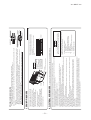
Tapping screws
(for installation board ø4 X 25mm)
Wood screws
(for remote control switch holder ø3.5 X 16mm)
Battery [R03 (AAA, Micro) 1.5V]
Air-cleaning filters
Filter holders
(Attached to the front panel of indoor unit)
Insulation (#486 50 x 100 t3)
4
5
6
7
8
9
1
Piping cover
(for insulation of connection piping)
Saw
Tape measure
Hammer
Spanner wrench
Torque wrench
Hole core drill (65mm in diameter)
3
4
5
6
7
8
Gauge for projection adjustment
Used when flare is made by using
conventional flare tool
(
Pipe bender
13
Flaring tool set
)
specifically
( Designed
)
for R410A
Designed specifically
Gas leak detector (
)
for R410A
Wrench key (Hexagon) [4m/m]
12
11
10
9
Knife
2
~ 82.0N·m
( 14.0
(1.4 ~ 8.2kgf·m) )
Plus headed driver
1
Necessary tools for the installation work
1
Drain hose (extension hose)
1
Inclination plate
1
1
Sleeve
Putty
1
Q’ty
1
2
Sealing plate
Option parts
1
Remote control holder
3
1
Wireless remote control
2
1
Installation board
(Attached to the rear of the indoor unit)
Q’ty
1
Standard accessories (Installation kit)
Accessories for indoor unit
Standard
hole
Mounting
board
Bolt
(M6 12)
Mounting
board
Max.10
Nut
(M6)
Fixing on concrete wall
Use of nut anchor
Use of bolt anchor
Outdoor side
b Top
○ Tape only the portion
that goes through the
wall.
○ Always tape the wiring
with the piping.
Sufficient care must be taken not to damage
the panel when connecting pipes.
○ Hold the bottom of the
piping and fix direction
before stretching it and
shaping it.
Drain hose
Pipings
Taping of the exterior
In case of piping in the right rear direction
Shaping of pipings
Thickness of the wall + 1.5cm
Indoor side
b
Turn to
tighten
Outdoor side
a
c
Installed state
Wood screws
106
53.5
Piping hole (ø65)
For bolt anchor
and nut anchor
349
50
Space
50 for service
25
Right-hand-side piping
Piping in the right direction
Piping in the right rear direction
Left
Left downward
Left
Downward rear
Rear
Right
Piping is possible in the rear, left, left rear, left downward, right or downward direction.
Piping in the left direction
Piping in the left rear direction
Left-hand-side piping
299
4. Connect the drain hose.
○ Remove it with hand or pliers.
2. Remove the drain cap.
Piping hole (ø65)
Piping for Liquid 703.5
Drain hose 792 (ø16)
106
(Unit : mm)
○ Insert the drain cap which was removed ○ Insert the drain hose securely, making
at procedure “2” securely using a
rotate. And install the screw.
hexagonal wrench etc.
Note: Be careful that If it is not inserted
securely, water leakage may
Note: Be careful that If it is not inserted
occur.
securely, water leakage may occur.
3. Insert the drain cap.
○ Remove the screw and drain hose,
making it rotate.
1. Remove the drain hose
50
Space
for service 100
77
Piping for Gas 633.5
886
450
Indoor unit
Installation board
INSTALLATION SPACE (INDOOR UNIT) (FRONT VIEW)
• Matters of special notice when piping from left or central/rear of the unit.
[Top view]
[Drain hose changing procedures]
○ In case of rear piping draw out, cut off the lower
and the right side portions of the sleeve collar.
Installing the support of piping
○ Drill a hole with whole core drill.
Indoor side
ø65
5
Sleeve (sold separately)
Wireless remote control
putty
Outdoor side
Remote control holder
putty
Indoor side
Installation board
10 cm m
inim
from the um
wall
6.5 cm minimum from the ceiling
Relation between setting plate and indoor unit
Completely seal the hole on
the wall with putty. Otherwise,
furniture, or other, may be
wetted by leaked water or
dewing.
CAUTION
5 cm minimum
from the wall
When drilling the wall that contains a metal lath, wire lath or metal plate, be sure to use pipe hole sleeve sold separately.
Drilling of holes and fixture of sleeve (Option parts)
level by turning the board
with the standard hole as
the center.
○ Adjust so the board will be
be conducted with eight screws in a temporary tightened state.
○ Adjustment of the installation board in the horizontal direction is to
Mating mark for
level surface
Look for the inside wall structures (Intermediats support or pillar
and firmly install the unit after level surface has been checked.)
610
450
Installation of Installation board
INSTALLATION OF INDOOR UNIT
○ A place where the air conditioner can be received the signal surely during operating the wireless remote control.
○ Places where there is no affected by the TV and radio etc.
○ Do not place where exposed to direct sunlight or near heat devices such as a stove.
Wireless remote control
○ Where there is no obstructions to the air flow and where the cooled and heated air can be evenly distributed.
○ A solid place where the unit or the wall will not vibrate.
○ A place where there will be enough space for servicing. (Where space mentioned below can be secured)
○ Where wiring and the piping work will be easy to conduct.
○ The place where receiving part is not exposed to the direct rays of the sun or the strong rays of the street lighting.
○ A place where it can be easily drained.
○ A place separated at least 1m away from the television or the radio. (To prevent interference to images and sounds.)
○ Places where this unit is not affected by the high frequency equipment or electric equipment.
○ Avoid installing this unit in place where there is much oil mist.
○ Places where there is no electric equipment or household under the installing unit.
Indoor unit
(Install at location that meets the following conditions, after getting approval from the customer)
SELECTION OF INSTALLATION LOCATION
65 Space
for service
8.5
○ Before installation check that the power supply matches the air conditioner.
49.5
221.5
44.5
43 -
44.5
301.8
-
15 Space
for service 7.7
BEFORE INSTALLATION
'13 • SRK-T-147
Wall
Installation board
Indoor unit
2 Gently push the lower
part to secure the unit.
1 Pass the pipe through
the hole in the wall,
and hook the upper
part of the indoor unit
to the installation board.
Installation Steps
-
Press
Remove
44 -
0.0 - 0.5
0.0 - 0.5
0.0 - 0.5
0.0 - 0.5
ø6.35
ø9.52
ø12.7
ø15.88
Measurement B (mm)
Conventional (R22) flare tool
Clutch type
Wing nut type
1.5 - 2.0
1.0 - 1.5
1.5 - 2.0
1.0 - 1.5
1.0 - 1.5
2.0 - 2.5
2.0 - 2.5
1.0 - 1.5
To remove / To install
Approx. 80
Wavy
The gap to the ground is
5 cm or less.
The drain hose
tip is in the gutter.
Odor from
the gutter
Otherwise water leak may occur.
○Installing
① Remove the air filter.
② Cover the unit with the front panel.
③ Tighten the screw (A) 2pcs / screw
(B) 3pcs to fix the front panel.
④ Install the air filter.
⑤ Install the air inlet panel.
Screw (B)
Position it so that the slit area faces upward.
Use an attached insulation pad for heat insulation.
Screw (B)
Screw (A)
Screw (B)
Air filter
Screw (A)
Air inlet panel
Latch
Cover the exterior portion with outer tape and
shape the piping so it will match the contours
of the route that the piping to take.
Also fix the wiring and pipings to the wall with
clamps.
Front panel
Connection wiring,
Earth wiring
Outer tape
Drain hose
Wood screw
Clamp
Refrigerant piping
Finishing work and fixing
• Cover the indoor unit s flare-connected joints, after they are checked for a gas leak, with an indoor unit
heat insulating material and then wrap them with a tape with an attached insulation pad placed over
the heat insulating material’s slit area.
Vinyl tape
Cover the coupling with insulator and then cover it with tapes.
Insulation of the connection portion
How to remove and install the front panel
If FDC71VNP is connected, use reducer at gas side
of indoor unit to change the pipe size from ø15.88 to
ø12.7. (Reducer is attached in the outdoor unit
accessory)
Do not apply excess torque to the flared nuts.
Otherwise, the flared nuts may check depending.
CAUTION
○ Connect the pipes on both liquid and gas sides.
○ Tighten the nuts to the following torque.
Liquid side (ø6.35) : 14.0 - 18.0 N·m (1.4 - 1.8 kgf·m)
Gas side (ø9.52) : 34.0 - 42.0 N·m (3.4 - 4.2 kgf·m)
(ø12.7) : 49.0 - 61.0 N·m (4.9 - 6.1 kgf·m)
(ø15.88) : 68.0 - 82.0 N·m (6.8 - 8.2 kgf·m)
(Do not turn)
The drain hose
tip is in water.
Wall
CAUTION Go through all installation steps and check if the drainage is all right.
Pipe accommodating section
Gutter
○ Pour water to the drain pan located under the heat exchanger, and ensure that the water is discharged outdoor.
○ When the extended drain hose is indoor, securely insulate it with a heat insulator available in the market.
Higher than specified
○Removing
① Remove the air inlet panel.
② Remove the screw (A) 2pcs / screw
(B) 3pcs fixing to the front panel.
③ Remove the 3 latches in the upper
section of the front panel and then
remove the front panel from the unit.
Use a flare tool designed for R410A or a conventional flare tool.
Please note that measurement B (protrusion from the flaring block) will vary depending on the
type of a flare tool in use.
If a conventional flare tool is used, please use a copper pipe gauge or a similar instrument to
check protrusion so that you can keep measurement B to a correct value.
Clutch type flare tool for
R410A
Copper pipe diameter
Do not apply refrigerating machine
oil to the flared surface.
CAUTION
Liquid side
Gas side
Drainage
○ Arrange the drain hose in a downward angle.
○ Avoid the following drain piping.
Open/close and detachment/attachment of the air inlet panel
Copper pipe
Measurement B
○ Install the removed flared nuts to the pipes to be connected,
then flared the pipes.
A
Dimension A
Liquid side ø6.35 : 9.1 (mm)
Gas side ø9.52 : 13.2 (mm)
ø12.7 : 16.6 (mm)
ø15.88 : 19.7 (mm)
Indoor
Connection
The marked portion of the indoor unit base lower latch.
1 Push up at the marked portion of the indoor unit base lower latch, and slightly pull it toward
you. (both right and left hand sides) (The indoor unit base lower latch can be removed from
the installation board)
2 Push up the indoor unit upward. So the indoor unit will be removed from the installation board.
• How to remove the indoor unit from the installation board
Since this air conditioner has been designed to collect dew drops on the rear
surface to the drain pan, do not attach the power cord above the gutter.
○ To open, pull the panel at both ends of lower part
and release latches, then pull up the panel until
you feel resistance.
(The panel stops at approx. 60°open position)
○ To close, hold the panel at both ends of lower
part to lower downward and push it slightly until
the latch works.
○ To remove, pull up the panel to the position
shown in right illustration and pull it toward you.
○ To install, insert the panel arm into the slot on the
front panel from the position shown in right
illustration, hold the panel at both ends of lower
part, lower it downward slowly, then push it
slightly until the latch works.
Flaring
block
• Flaring work
○ Remove the flared nuts. (on both liquid and gas sides)
(Do not turn)
Indoor
Keep the openings of the pipes covered with tapes etc. to prevent dust, sand, etc. from entering them.
90 ± 0.5°
Preparation
CONNECTION OF REFRIGERANT PIPINGS
Indoor unit base latch
Installation board
Latch (2 locations)
Fixing of indoor unit
'13 • SRK-T-147
CAUTION
Wiring Clamp
Lid
Installing the air-cleaning filters
Filter holder
-
45 -
Cover
5 Wood screws
ø3.5 X 16
2 Wireless remote control
○ Conventionally, operate the wireless remote control by holding
in your hand.
○ Avoid installing it on a clay wall etc.
The power supply voltage is correct as the rating.
No gas leaks from the joints of the operation valve.
Power cables and crossover wires are securely fixed to the terminal board.
The screw of the lid is tightened securely.
After installation
1 minute.
2 Point the wireless remote control that was set
according to the procedure described on the
left side at the indoor unit and send a signal by
pressing the ACL switch on the wireless remote control.
Since the signal is sent in about 6 seconds after the ACL switch is pressed,
point the wireless remote control at the indoor unit for some time.
3 Check that the reception buzzer sound "pip" is emitted from the
indoor unit.
At completion of the setting, the indoor unit emits a buzzer sound
"pip". (If no reception tone is emitted, start the setting from the
beginning again.)
1 Turn off the power supply, and turn it on after
Setting an indoor unit
Operation valve is fully open.
The pipe joints for indoor and outdoor pipes have been insulated.
TIM
E
S ET
UP
AC
L
pip
Reception
In connecting an interface, connect to the respective terminal securely with the connection harness
supplied with an optional “Interface connection kit SC-BIKN-E ” and fasten the connection harness
onto the indoor control box with the clamp supplied with the kit.
For more details, please refer to the user’s manual of your “Interface connection kit SC-BIKN-E ”.
1 Remove the air inlet panel, lid and front panel.
2 Remove the control cover. (Remove the screw.)
3 There is a terminal (respectively marked with CNS) for the indoor control board.
Air conditioning operation is normal.
No abnormal noise.
Water drains smoothly.
Protective functions are not working.
Test run
CNS terminal
The wireless remote control is normal.
Operation of the unit has been explained to the customer. (Three-minutes restart preventive timer)
When the air conditioner is restarted or when changing the operation, the unit will not start operating for
approximately 3 minutes. This is to protect the unit and it is not a malfunction.
Screw
Indoor unit PCB
Control cover
CONCERNING TERMINAL CONNECTION FOR AN INTERFACE
3 Insert batteries. Close the cover.
Disconnect
switching line next
to the battery with
wire cutters.
1 Pull out the cover and take out batteries.
2 Disconnect the
Setting the wireless remote control
Check the following points again after completion of the installation, and before turning on the power. Conduct a test run again and ensure that the unit operates properly.
At the same time, explain to the customer how to use the unit and how to take care of the unit following the user’s manual.
Unit ON/OFF button
• Forced cooling operation
Turn on the power supply again after a while after turn off the power supply.
Then press continually the ON/OFF button 5 seconds or more.
INSTALLATION TEST CHECK POINTS
<How to pump down>
1 Connect charge hose to check joint of outdoor unit.
2 Liquid side : Close the liquid valve with hexagon wrench key.
Gas side : Fully open the gas valve.
Carry out cooling operation. (If indoor temperature is low, operate
forced cooling operation.)
3 After low pressure gauge become 0.01MPa, stop cooling operation
and close the gas valve.
○ In order to protect the environment, be sure to pump down (recovery of refrigerant).
○ Pump down is the method of recovering refrigerant from the indoor unit to the
outdoor unit when the pipes are removed from the unit.
HOW TO RELOCATE OR DISPOSE OF THE UNIT
Do not use new and
old batteries together.
CAUTION
6 Battery
○ Uncover the wireless remote control, and mount the batteries [R03 (AAA, Micro),
×2 pieces] in the body regularly.
(Fit the poles with the indication marks, + & − without fail)
Fixing to pillar or wall
When two air conditioners are installed in the same room, use this setting when the two air conditioners are not operated with one wireless remote control. Set the
wireless remote control and indoor unit.
Air-cleaning
filter
1. Open the air inlet panel and remove the air filters.
2. Install the air-cleaning filter in the filter holders, and then install the filter holders in the air conditioner.
• Each air-cleaning filter can be installed in the left or right filter holder.
3. Install the air filters and close the inlet panel.
Mounting method of battery
• Earth wire shall be Yellow/Green (Y/G) in color and longer than other AC wires for safety reason.
1 2/N 3
The screw of the lid is
tightened securely.
INSTALLING TWO AIR CONDITIONERS IN THE SAME ROOM
H05RNR4G1.5 (example) or 245IEC57
H Harmonized cable type
05 300/500 volts
R Natural-and/or synth, rubber wire insulation
N Polychloroprene rubber conductors insulation
R Stranded core
4or5 Number of conductors
G One conductor of the cable is the earth conductor
(yellow/green)
1.5 Section of copper wire (mm2)
Use cables for interconnection wiring to avoid loosening of the wires.
CENELEC code for cables Required field cables.
In case of faulty wiring connection, the indoor unit stops, and then
the run lamp turns on and the timer lamp blinks.
Terminal block
④
⑤
○
①
②
③
INSTALLATION OF WIRELESS REMOTE CONTROL
Open the air inlet panel.
Remove the lid.
Remove the wiring clamp.
Connect the connecting wire securely to the terminal block.
1) Connect the connection wire securely to the terminal
block. If the wire is not affixed completely, contact will be
poor, and it is dangerous as the terminal block may heat
up and catch fire.
2) Take care not to confuse the terminal numbers for indoor
and outdoor connections.
5 Fix the connecting wire by wiring clamp.
6 Attach the lid.
7 Close the air inlet panel.
1
2
3
4
Mounting of connecting wires
Preparation of indoor unit
ELECTRICAL WIRING WORK
○
'13 • SRK-T-147
R410A REFRIGERANT USED
RCR012A002
-
46 -
• Ventilate the working area well in the event of refrigerant leakage during
installation.
If the refrigerant comes into contact with naked flames, poisonous gas is produced.
• Use the prescribed pipes, flare nuts and tools for R410A.
Using existing parts (for R22 or R407C) can cause the unit failure and serious
accidents due to burst of the refrigerant circuit.
• Tighten the flare nut by torque wrench with specified method.
If the flare nut were tightened with excess torque, this may cause burst and
refrigerant leakage after a long period.
• Do not open the operation valves for liquid line and gas line until
completed refrigerant piping work, air tightness test and evacuation.
If the compressor is operated in state of opening operation valves before
completed connection of refrigerant piping work, air can be sucked into refrigerant
circuit, which can cause bust or personal injury due to anomalously high pressure
in the refrigerant.
• The electrical installation must be carried out by the qualified electrician
in accordance with “the norm for electrical work” and “national wiring
regulation”, and the system must be connected to the dedicated circuit.
Power supply with insufficient capacity and incorrect function done by improper
work can cause electric shocks and fire.
• Be sure to shut off the power before starting electrical work.
Failure to shut off the power can cause electric shocks, unit failure or incorrect
function of equipment.
• Be sure to use the cables conformed to safety standard and cable
ampacity for power distribution work.
Unconformable cables can cause electric leak, anomalous heat production or fire.
• This appliance must be connected to main power supply by means of a
WARNING
CAUTION
Always do it according to the instruction.
• Do not perform any change of protective device itself or its setup
condition.
The forced operation by short-circuiting protective device of pressure switch and
temperature controller or the use of non specified component can cause fire or
burst.
circuit breaker or switch (fuse:20A) with a contact separation of at least
3mm.
• Arrange the wiring in the control box so that it cannot be pushed up
further into the box. Install the service panel correctly.
Incorrect installation may result in overheating and fire.
• Use the prescribed cables for electrical connection, tighten the cables
securely in terminal block and relieve the cables correctly to prevent
overloading the terminal blocks.
Loose connections or cable mountings can cause anomalous heat production or fire.
• Be sure to fix up the service panels.
Incorrect fixing can cause electric shocks or fire due to intrusion of dust or water.
• Be sure to switch off the power supply in the event of installation,
inspection or servicing.
If the power supply is not shut off, there is a risk of electric shocks, unit failure or
personal injury due to the unexpected start of fan.
• Stop the compressor before removing the pipe after shutting the
operation valve on pump down work.
If the pipe is removed when the compressor is in operation with the operation valve
open, air would be mixed in the refrigeration circuit and it could cause explosion
and injuries due to abnormal high pressure in the cooling cycle.
• Only use prescribed optional parts. The installation must be carried out
by the qualified installer.
If you install the system by yourself, it can cause serious trouble such as water
leaks, electric shocks, fire.
• Be sure to wear protective goggles and gloves while at work.
• Earth leakage breaker must be installed.
If the earth leakage breaker is not installed, it can cause electric shocks.
Never do it under any circumstances.
• Keep the installation manual together with owner’s manual at a place where any user can read at any time.
Moreover if necessary, ask to hand them to a new user.
• For installing qualified personnel, take precautions in respect to themselves by using suitable protective
clothing, groves, etc., and then perform the installation works.
• Please pay attention not to fall down the tools, etc. when installing the unit at the high position.
• If unusual noise can be heard during operation, consult the dealer.
• The meanings of “Marks” used here are shown as follows:
• Do not bundling, winding or processing for the power cord. Or, do not
• Ensure that no air enters in the refrigerant circuit when the unit is
deforming the power plug due to tread it.
installed and removed.
This may cause fire or heating.
If air enters in the refrigerant circuit, the pressure in the refrigerant circuit
• Do not run the unit with removed panels or protections.
becomes too high, which can cause burst and personal injury.
Touching rotating equipments, hot surfaces or high voltage parts can cause
• Do not processing, splice the power cord, or share a socket with other power plugs.
personal injury due to entrapment, burn or electric shocks.
This may cause fire or electric shock due to defecting contact, defecting insulation
and over-current etc.
• Installation must be carried out by the qualified installer.
If you install the system by yourself, it may cause serious trouble such as water leaks,
electric shocks, fire and personal injury, as a result of a system malfunction. Do not
carry out the installation and maintenance work except the by qualified installer.
• Install the system in full accordance with the installation manual.
Incorrect installation may cause bursts, personal injury, water leaks, electric
shocks and fire.
• Be sure to use only for household and residence.
If this appliance is installed in inferior environment such as machine shop and etc.,
it can cause malfunction.
• When installing in small rooms, take prevention measures not to
exceed the density limit of refrigerant in the event of leakage, referred
by the formula (accordance with ISO5149).
If the density of refrigerant exceeds the limit, please consult the dealer and install
the ventilation system, otherwise lack of oxygen can occur, which can cause serious
accident.
• Use the original accessories and the specified components for
installation.
If parts other than those prescribed by us are used, It may cause water leaks,
electric shocks, fire and personal injury.
• Install the unit in a location with good support.
Unsuitable installation locations can cause the unit to fall and cause material
damage and personal injury.
• Ensure the unit is stable when installed, so that it can withstand
earthquakes and strong winds.
Unsuitable installation locations can cause the unit to fall and cause material
damage and personal injury.
• Read the “SAFETY PRECAUTIONS” carefully first of all and strictly follow it during the installation work in order
to protect yourself.
• The precautionary items mentioned below are distinguished into two levels,
CAUTION .
WARNING and
WARNING : Wrong installation would cause serious consequences such as injuries or death.
CAUTION : Wrong installation might cause serious consequences depending on circumstances.
Both mentions the important items to protect your health and safety so strictly follow them by any means.
• Be sure to confirm no anomaly on the equipment by commissioning after completed installation and explain the
operating methods as well as the maintenance methods of this equipment to the user according to the owner’s
manual.
SAFETY PRECAUTIONS
• This installation manual deals with outdoor units and general installation specifications only. For indoor units, refer to page 42.
• When install the unit, be sure to check whether the selection of installation place, power supply specifications, usage limitation (piping length, height differences between indoor and outdoor units, power
supply voltage and etc.) and installation spaces.
INSTALLATION MANUAL FOR OUTDOOR UNIT
(2) Installation of outdoor unit
Models SRC63ZMA-S, 71ZMA-S, 80ZMA-S
'13 • SRK-T-147
CAUTION
-
47 -
Check before installation work
2
1
Option parts
Sealing plate
Sleeve
Inclination plate
Putty
Drain hose (extension hose)
Piping cover
f
(for insulation of connection piping)
a
b
c
d
e
1
1
1
1
1
1
1
2
3
4
5
6
7
8
Plus headed driver
Knife
Saw
Tape measure
Hammer
Spanner wrench
Torque wrench [14.0~82.0N·m (1.4~8.2kgf·m)]
Hole core drill (65mm in diameter)
Necessary tools for the installation work
9 Wrench key (Hexagon) [4m/m]
10 Vacuum pump
Vacuum pump adapter (Anti-reverse flow type)
11
(Designed specifically for R410A)
12 Gauge manifold (Designed specifically for R410A)
13 Charge hose (Designed specifically for R410A)
14 Flaring tool set (Designed specifically for R410A)
15 Gas leak detector (Designed specifically for R410A)
Gauge for projection adjustment
16
(Used when flare is made by using conventional flare tool)
• Do not use any refrigerant other than R410A. R410A will rise to pressure about 1.6 times higher than that of a conventional refrigerant.
A cylinder containing R410A has a pink indication mark on the top.
• A unit designed for R410A has adopted a different size indoor unit operation valve charge port and a different size check joint provided in the unit to prevent the charging of a wrong refrigerant by mistake.
The processed dimension of the flared part of a refrigerant pipe and a flare nut’s parallel side measurement have also been altered to raise strength against pressure.
Accordingly, you are required to arrange dedicated R410A tools listed in the table on the left before installing or servicing this unit.
• Do not use a charge cylinder. The use of a charge cylinder will cause the refrigerant composition to change, which results in performance degradation.
• In charging refrigerant, always take it out from a cylinder in the liquid phase.
• All indoor units must be models designed exclusively for R410A. Check connectable indoor unit models in a catalog, etc. (A wrong indoor unit, if connected into the system, will impair proper system operation)
Notabilia as a unit designed for R410A
Q’ty
Accessories for outdoor unit
1 Grommet (Heat pump type only)
2 Drain elbow (Heat pump type only)
• Model name and power source
• Refrigerant piping length
• Piping, wiring and miscellaneous small parts
• Indoor unit installation manual
Q’ty
• Do not install the outdoor unit in a location where insects and small
animals can inhabit.
Insects and small animals can enter the electric parts and cause damage or fire.
Instruct the user to keep the surroundings clean.
• Do not use the base flame for outdoor unit which is corroded or damaged
due to long periods of operation.
Using an old and damage base flame can cause the unit falling down and cause
personal injury.
• Do not use any materials other than a fuse with the correct rating in the
location where fuses are to be used.
Connecting the circuit with copper wire or other metal thread can cause unit
failure and fire.
• Do not touch any buttons with wet hands.
It can cause electric shocks.
• Do not touch any refrigerant pipes with your hands when the system is in
operation.
During operation the refrigerant pipes become extremely hot or extremely cold
depending the operating condition, and it can cause burn injury or frost injury.
• Do not touch the suction or aluminum fin on the outdoor unit.
This may cause injury.
• Do not put anything on the outdoor unit and operating unit.
This may cause damage the objects or injury due to falling to the object.
• Do not use the unit for special purposes such as storing foods, cooling
precision instruments and preservation of animals, plants or art.
• Do not clean up the unit with water.
• Do not install the outdoor unit in the locations listed below.
• Locations where discharged hot air or operating sound of the outdoor unit can
bother neighborhood.
• Locations where outlet air of the outdoor unit blows directly to an animal or
plants. The outlet air can affect adversely to the plant etc.
• Locations where vibration can be amplified and transmitted due to insufficient
strength of structure.
• Locations where vibration and operation sound generated by the outdoor unit
can affect seriously (on the wall or at the place near bed room).
• Locations where an equipment affected by high harmonics is placed (TV set or
radio receiver is placed within 1m).
• Locations where drainage cannot run off safely.
It can affect surrounding environment and cause a claim.
• Do not install the unit near the location where leakage of combustible
gases can occur.
If leaked gases accumulate around the unit, it can cause fire.
• Do not install the unit where corrosive gas (such as sulfurous acid gas etc.)
or combustible gas (such as thinner and petroleum gases) can accumulate
or collect, or where volatile combustible substances are handled.
Corrosive gas can cause corrosion of heat exchanger, breakage of plastic parts
and etc. And combustible gas can cause fire.
• Do not install nor use the system close to the equipment that generates
electromagnetic fields or high frequency harmonics.
Equipment such as inverters, standby generators, medical high frequency
equipments and telecommunication equipments can affect the system, and cause
malfunctions and breakdowns. The system can also affect medical equipment and
telecommunication equipment, and obstruct its function or cause jamming.
• Do not install the unit in the locations listed below.
• Locations where carbon fiber, metal powder or any powder is floating.
• Locations where any substances that can affect the unit such as sulphide gas,
chloride gas, acid and alkaline can occur.
• Vehicles and ships.
• Locations where cosmetic or special sprays are often used.
• Locations with direct exposure of oil mist and steam such as kitchen and
machine plant.
• Locations where any machines which generate high frequency harmonics are
used.
• Locations with salty atmospheres such as coastlines.
• Locations with heavy snow (If installed, be sure to provide base flame and snow
hood mentioned in the manual).
• Locations where the unit is exposed to chimney smoke.
• Locations at high altitude (more than 1000m high).
• Locations with ammonic atmospheres.
• Locations where heat radiation from other heat source can affect the unit.
• Locations without good air circulation.
• Locations with any obstacles which can prevent inlet and outlet air of the unit.
• Locations where short circuit of air can occur (in case of multiple units
installation).
• Locations where strong air blows against the air outlet of outdoor unit.
• Locations where something located above the unit could fall.
It can cause remarkable decrease in performance, corrosion and damage of
components, malfunction and fire.
• When perform the air conditioner operation (cooling or drying operation)
in which ventilator is installed in the room. In this case, using the air
conditioner in parallel with the ventilator, there is the possibility that
drain water may backflow in accordance with the room lapse into the
negative pressure status. Therefore, set up the opening port such as
incorporate the air into the room that may appropriate to ventilation (For
example; Open the door a little). In addition, just as above, so set up the
opening port if the room lapse into negative pressure status due to
register of the wind for the high rise apartment etc.
• Take care when carrying the unit by hand.
• Use the circuit breaker for all pole correct capacity. Circuit breaker
If the unit weights more than 20kg, it must be carried by two or more persons. Do
should be the one that disconnect all poles under over current.
not carry by the plastic straps, always use the carry handle when carrying the unit
Using the incorrect circuit breaker, it can cause the unit malfunction and fire.
by hand. Use gloves to minimize the risk of cuts by the aluminum fins.
• Install isolator or disconnect switch on the power supply wiring in
• Dispose of any packing materials correctly.
accordance with the local codes and regulations.
Any remaining packing materials can cause personal injury as it contains nails and
The isolator should be locked in OFF state in accordance with EN60204-1.
wood. And to avoid danger of suffocation, be sure to keep the plastic wrapper
• After maintenance, all wiring, wiring ties and the like, should be returned
away from children and to dispose after tear it up.
to their original state and wiring route, and the necessary clearance from
• Be sure to insulate the refrigerant pipes so as not to condense the
all metal parts should be secured.
ambient air moisture on them.
• Secure a space for installation, inspection and maintenance specified in
Insufficient insulation can cause condensation, which can lead to moisture
the manual.
damage on the ceiling, floor, furniture and any other valuables.
Insufficient space can result in accident such as personal injury due to falling from
the installation place.
• Carry out the electrical work for ground lead with care.
Do not connect the ground lead to the gas line, water line, lightning conductor or telephone line’s ground lead. Incorrect grounding can cause unit faults such as electric shocks due to short-circuiting.
'13 • SRK-T-147
Heavy
Pad
2 Install the unit under eaves or provide the roof
on site.
Since drain water generated by defrost control may freeze, following measures are required.
• Do not execute drain piping work by using a drain elbow and drain grommets (accessories).
[Refer to Drain piping work.]
1 Install the unit on the base so that the bottom is
higher than snow cover surface.
(1) If the unit is installed in the area where the snow will accumulate, following measures are required.
The bottom plate of unit and intake, outlet may be blocked by snow.
4) Caution about selection of installation location
Be careful of the following conditions and choose an installation place.
• Where air is not trapped.
• Where the installation fittings can be firmly installed.
• Where wind does not hinder the intake and outlet pipes.
• Out of the heat range of other heat sources.
• A place where stringent regulation of electric noises is applicable.
• Where it is safe for the drain water to be discharged.
• Where noise and hot air will not bother neighboring residents.
• Where snow will not accumulate.
• Where strong winds will not blow against the outlet pipe.
• A place where no TV set or radio receiver is placed within 1m.
(If electrical interference is caused, seek a place less likely to cause the problem)
• If a operation is conducted when the outdoor air temperature is –5 C lower, the outdoor unit should be
installed at a place where it is not influenced by natural wind.
• Where it is likely that the unit is subjected to strong winds, provide wind guards according to the
following guidelines. Strong winds can cause performance degradation, an accidental stop due to a rise of
high pressure and a broken fan.
3) Selecting the installation location
• The right hand side of the unit as viewed from the front (diffuser side) is heavier.
A person carrying the right hand side must take heed of this fact. A person
carrying the left hand side must hold with his right hand the handle provided on
the front panel of the unit and with his left hand the corner column section.
2) Portage
• Deliver the unit as close as possible to the installation site before removing it from
the packaging.
• When you have to unpack the unit for a compelling reason before you haul it to
the installation point, hoist the unit with nylon slings or ropes and protection pads
so that you may not damage the unit.
1) Delivery
•
•
•
•
•
60
Outlet
580
880
Intake
87.9
Use a thicker block to anchor deeper.
150
Size
Wind
direction
100
250
L4
250
150
Open
250
II
Intake
L2
Outlet
Intake
L3
L1
L4
(mm)
III
250
100
500
Open
(service
space )
The height of a wall is 1200mm or less.
Open
300
L3
I
L1
L2
Example installation
Wind
direction
2 Install so the direction of the air from the
blowing outlet will be perpendicular to the
direction of the wind.
In installing the unit, fix the unit’s legs with bolts specified on the above.
The protrusion of an anchor bolt on the front side must be kept within 15mm.
Securely install the unit so that it does not fall over during earthquakes or strong winds, etc.
Refer to the above illustrations for information regarding concrete foundations.
Install the unit in a level area. (With a gradient of 5mm or less.) Improper installation can result in a
compressor failure, broken piping within the unit and abnormal noise generation.
Use a long block to extend the width.
Fasten with bolts
(M10-12)
2 Notabilia for installation
150
15
1 Anchor bolt fixed position
6) Installation
• Walls surrounding the unit in the four sides are not
acceptable.
• There must be a 1-meter or larger space in the above.
• When more than one unit are installed side by side,
provide a 250mm or wider interval between them as a
service space. In order to facilitate servicing of
controllers, please provide a sufficient space between
units so that their top plates can be removed easily.
• Where a danger of short-circuiting exists, install guide
louvers.
• When more than one unit are installed, provide sufficient
intake space consciously so that short-circuiting may not
occur.
• Where piling snow can bury the outdoor unit, provide
proper snow guards.
5) Installation space
Over 500mm
1 Place the unit outlet side is turned to the wall.
(2) If the unit can be affected by strong wind, following measures are required.
Strong wind can cause damage of fan (fan motor), or can cause performance degradation, or can trigger
anomalous stop of the unit due to rising of high pressure.
When a unit is hoisted with slings for haulage, take into consideration the offset of its gravity center position.
If not properly balanced, the unit can be thrown off-balance and fall.
340
CAUTION
(Take particular care in carrying in or moving the unit, and always perform such an operation with two or more persons.)
19
380
48 418
19
1. HAULAGE AND INSTALLATION
'13 • SRK-T-147
20m or less
When the outdoor unit is positioned lower,
-
49 -
Select pipes having a wall thickness larger than the specified
minimum pipe thickness.
• Carry out the on site piping work with the operation valve fully closed.
• Give sufficient protection to a pipe end (compressed and blazed, or with an
adhesive tape) so that water or foreign matters may not enter the piping.
• Bend a pipe to a radius as large as practical (R100 ~ R150). Do not bend a pipe
repeatedly to correct its form.
• Flare connection is used between the unit and refrigerant pipe. Flare a pipe after
engaging a flare nut onto it. Flare dimensions for R410A are different from
those for conventional R407C. Although we recommend the use of flaring tools
designed specifically for R410A, conventional flaring tools can also be used by
adjusting the measurement of protrusion B with a protrusion control gauge.
• The pipe should be anchored every 1.5m or less to isolate the vibration.
• Tighten a flare joint securely.
Please remove the screw of a side cover and
remove to the front.
O-type pipe
1.0
ø15.88
Side cover
The screw of the
side cover is
tightened securely.
*Phosphorus deoxidized seamless copper pipe ICS 23.040.15, ICS 77.150.30
O-type pipe
0.8
Pipe material*
ø6.35
Pipe diameter [mm]
Minimum pipe wall thickness [mm]
Take care so that installed pipes may not touch components within a unit.
If touching with an internal component, it will generate abnormal sounds and/or vibrations.
How to remove the side cover
IMPORTANT
4) On-site piping work
NOTE
• Select refrigerant pipes of the table shown on the right wall thickness and
material as specified for each pipe size.
3) Refrigerant pipe wall thickness and material
ø6.35
ø6.35
ø15.88
Refrigerant piping (branch pipe L)
ø15.88
ø6.35
Flare
ø15.88
Flare
Outdoor unit connected
Indoor unit connected
Without nitrogen gas, a large quantity of foreign matters
(oxidized film) are created, causing a critical failure from
capillary tube or expansion valve clogging.
About brazing
Brazing must be performed under a nitrogen gas flow.
Liquid pipe
Gas pipe
Determine refrigerant pipe size pursuant to the following guidelines based
on the indoor unit specifications.
When pipe is brazing.
The use restrictions appearing in the table above are applicable to the standard pipe size combinations shown in the table below.
H
20m or less
2) Determination of pipe size
CAUTION
Elevation difference between
indoor and outdoor units
L
H
30m or less
Main pipe length
When the outdoor unit is positioned higher,
Marks appearing in the
drawing on the right
Dimensional restrictions
Restrictions
Nitrogen
• Check the following points in light of the indoor unit specifications and the installation site.
• Observe the following restrictions on unit installation and use. Improper installation can result in a compressor failure or performance degradation.
1) Restrictions on unit installation and use
Outdoor unit
A
<N2>
Brazing
(mm)
0
–04
9.1
19.7
A
Nitrogen
gas
ø6.35
ø15.88
Copper pipe
outer diameter
(mm)
0 ~ 0.5
1.0 ~ 1.5
In the case of a rigid (clutch) type
With an R410A tool With a conventional tool
Hand
0.5MPa
L
Indoor unit
Secondary side
Relief valve
Primary side
Station valve
Copper pipe protrusion for flaring : B
ø6.35
ø15.88
Copper pipe
outer diameter
Flared pipe end : A
Only use nitrogen gas (N2)
Taping
Plug the end of the pipe with tape, or other
material, and fill the pipe with nitrogen gas.
H
B
2. REFRIGERANT PIPING WORK
'13 • SRK-T-147
Tightening angle ()
45 ~ 60
15~ 20
Tightening torque (N·m)
14 ~ 18
68~ 82
Operation valve size (mm)
ø6.35 (1/4")
ø15.88 (5/8")
<Work flow>
-
50 -
Fill refrigerant
Vacuum gauge check
Confirm that the vacuum gauge indicator does not rise even if
the system is left for one hour or more.
Vacuuming completed
Run the vacuum pump for at least one hour after the vacuum
gauge shows –0.1MPa or lower. (–76cmHg or lower)
Vacuuming begins
Air tightness test completed
1.80
0.025
15
Installation’s pipe length (m)
covered without additional
refrigerant charge
* When an additional charge volume calculation result is negative, it is not necessary to charge refrigerant
additionally.
• For an installation measuring 15m or shorter in pipe length, please charge the refrigerant volume charged
for shipment at the factory, when you recharge refrigerant after servicing etc.
Additional charge volume (kg) = { Main length (m) – Factory charged volume 15 (m) } x 0.025 (kg/m)
Formula to calculate the volume of additional refrigerant required
• Thisunitcontains factory charged refrigerant covering 15m of refrigerant piping and additional refrigerant
charge on the installation site is not required for an installation with up to 15m refrigerant piping.
When refrigerant piping exceeds 15m, additionally charge an amount calculated from the pipe length and
the above table for the portion in excess of 15m.
Refrigerant volume charged
for shipment at the factory
(kg)
Additional charge volume (kg)
per meter of refrigerant piping
(liquid pipe ø6.35)
(1) Calculate a required refrigerant charge volume from the following table.
7) Additional refrigerant charge
Pressure gauge
Compound pressure gauge
Indoor unit
Handle Lo
Gauge manifold
(Designed specifically for R410A)
Handle Hi
Operation valve
Charge hose
(three-way valve)
(Designed specifically for R410A)
Vacuum pump adapter
Operation valve cap
(Anti-reverse flow type)
(Designed specifically for R410A)
Vacuum pump
Check joint
Charge hose (Designed specifically for R410A)
-0.1MPa
(-76cmHg)
Operation valve cap
ze
uri
Operation valve size
(mm)
ø6.35 (1/4")
ø15.88 (5/8")
10 ~ 12
Check joint blind nut
tightening torque (N·m)
NOTE Put down the refrigerant volume calculated from the pipe length onto the caution label attached
on the service panel.
• Since R410A refrigerant must be charged in the liquid phase, you should charge it, keeping the container
cylinder upside down or using a refrigerant cylinder equipped with a siphon tube.
• Charge refrigerant always from the liquid side service port with the operation valve shut. When you find it
difficult to charge a required amount, fully open the outdoor unit valves on both liquid and gas sides and
charge refrigerant from the gas (suction) side service port, while running the unit in the cooling mode. In
doing so, care must be taken so that refrigerant may be discharged from the cylinder in the liquid phase
all the time. When the cylinder valve is throttled down or a dedicated conversion tool to change liquid
phase refrigerant into mist is used to protect the compressor, however, adjust charge conditions so that
refrigerant will gasify upon entering the unit.
• In charging refrigerant, always charge a calculated volume by using a scale to measure the charge
volume.
• When refrigerant is charged with the unit being run, complete a charge operation within 30minutes.
Running the unit with an insufficient quantity of refrigerant for a long time can cause a compressor failure.
Operation valve cap
tightening torque (N·m)
20 ~ 30
30~ 40
Securely tighten the operation valve cap and the check joint blind nut after adjustment.
Operation valve
(two-way valve)
(2) Charging refrigerant
• To prevent a different oil from entering, assign dedicated tools, etc. to each refrigerant type. Under no circumstances must a
gauge manifold and a charge hose in particular be shared with other refrigerant types (R22, R407C, etc.).
• Use a counterflow prevention adapter to prevent vacuum pump oil from entering the refrigerant system.
Pay attention to the following points in addition to the above for the R410A and compatible machines.
When the system has remaining moisture
inside or a leaky point, the vacuum gauge
indicator will rise.
Check the system for a leaky point and
then draw air to create a vacuum again.
6) Evacuation
ss
Pre
Gas side
operation valve
Check joint
Use a torque wrench. If a torque wrench is not
available, fasten the flare nut manually first and then
tighten it further, using the left table as a guide.
Outdoor unit
Do not hold the valve cap area with a spanner.
1 Although outdoor and indoor units themselves have been tested for air tightness at the factory, check the connecting pipes after the installation work for air tightness
from the operation valve’s check joint equipped on the outdoor unit side. While conducting a test, keep the operation valve shut all the time.
a) Raise the pressure to 0.5MPa, and then stop. Leave it for five minutes to see if the pressure drops.
b) Then raise the pressure to 1.5MPa, and stop. Leave it for five more minutes to see if the pressure drops.
c) Then raise the pressure to the specified level (4.15MPa), and record the ambient temperature and the pressure.
d) If no pressure drop is observed with an installation pressurized to the specified level and left for about one day, it is acceptable. When the ambient temperature fall
1C, the pressure also fall approximately 0.01MPa. The pressure, if changed, should be compensated for.
e) If a pressure drop is observed in checking e) and a) – d), a leak exists somewhere. Find a leak by applying bubble test liquid to welded parts and flare joints and
repair it. After repair, conduct an air tightness test again.
2 In conducting an air tightness test, use nitrogen gas and pressurize the system with nitrogen gas from the gas side. Do not use a medium other than nitrogen gas
under any circumstances.
150
300
Recommended length of a tool handle (mm)
Fix both liquid and gas operation valves at the valve main bodies as illustrated on the right, and then fasten them,
applying appropriate fastening torque.
Do not apply force beyond proper fastening torque in tightening the flare nut.
5) Air tightness test
CAUTION
Close
• Tighten a flare joint securely.
'13 • SRK-T-147
-
51 -
Grommet
Drain hose
(To be procured on the installer’s part)
Do not put a grommet on
this hole.
This is a supplementary
drain hole to discharge
drain water, when a large
quantity of it is gathered.
CAUTION
Electrical installation work must be performed by an electrical installation service provider qualified by a power provider of the country.
Electrical installation work must be executed according to the technical standards and other regulations applicable to electrical installations in the country.
• Do not use any supply cord lighter than one specified in parentheses for each type below.
• braided cord (code designation 60245 IEC 51)
• ordinary tough rubber sheathed cord (code designation 60245 IEC 53)
• flat twin tinsel cord (code designation 60227 IEC 41)
Use polychloroprene sheathed flexible cord (code designation 60245 IEC57) for supply cords of parts of appliances for outdoor use.
• Ground the unit. Do not connect the grounding wire to a gas pipe, water pipe, lightning rod or telephone grounding wire.
If improperly grounded, an electric shock or malfunction may result.
• A grounding wire must be connected before connecting the power cable. Provide a grounding wire longer than the power cable.
• The installation of an impulse withstanding type earth leakage breaker is necessary. A failure to install an earth leakage breaker can result in an accident
such as an electric shock or a fire.
• Do not turn on the power until the electrical work is completed.
• Do not use a condensive capacitor for power factor improvement under any circumstances. (It dose not improve power factor, while it can cause an
abnormal overheat accident)
• For power supply cables, use conduits.
• Do not lay electronic control cables (remote control and signaling wires) and other cables together outside the unit. Laying them together can result in
the malfunctioning or a failure of the unit due to electric noises.
• Fasten cables so that may not touch the piping, etc.
• When cables are connected, make sure that all electrical components within the electrical component box are free of loose connector coupling or
terminal connection and then attach the cover securely. (Improper cover attachment can result in malfunctioning or a failure of the unit, if water
penetrates into the box.)
• Never use a shield cable.
• SRC-ZMA-S and SRC-YMA-S complies with the DRED (Demand Response Enabling Devices) standard AS/NZS4755.3.1 and supports demand response
modes 1, 2, and 3 (DRM1, 2, and 3). Since the air conditioner limits the electric power or energy by receiving the DRED input signal, the sense of
cooling operation or heating operation may deteriorate over time. The outdoor unit of this air conditioner is equipped with a terminal block for DRED
input and supports ELV (Extra-Low Voltage) complying with AS/NZS60335.1.
Liquid piping
Wires for connecting indoor
and outdoor units
Band (accessory)
RCR012A002
Insulation
Clearance
H05RNR4G1.5 (Example) or 245IEC57
H
Harmonized cable type
300/500 volts
05
Natural-and/or synth. rubber wire insulation
R
N
Polychloroprene rubber conductors insulation
R
Stranded core
4or5 Number of conductors
G
One conductor of the cable is the earth conductor
(yellow/green)
Section of copper wire (mm2)
1.5
Use cables for interconnection wiring to avoid loosening of the wires.
CENELEC code for cables Required field cables.
In case of faulty wiring connection, the indoor unit stops,
and then the run lamp turns on and the timer lamp blinks.
CAUTION
Gas piping
Exterior tape
Pipe cover (accessory)
• When condensed water needs to be led to a drain, etc., install
the unit on a flat base (supplied separately as an optional part)
or concrete blocks.
Then, please secure space for the drain elbow and the drain
hose.
For details of electrical cabling, refer to the indoor unit installation manual.
Drain elbow
Grommet
4. ELECTRICAL WIRING WORK
• Where you are likely to have several days of sub-zero
temperatures in a row, do not use a drain elbow and
drain grommets. (There is a risk of drain water freezing
inside and blocking the drain.)
• Condensed water may flow out from vicinity of
operation valve or connected pipes.
• Water may drip where there is a larger amount of drain
water. Seal around the drain elbow and drain
grommets with putty or adequate caulking material.
• Execute drain piping by using a drain elbow and drain
grommets supplied separately as accessories, where
water drained from the outdoor unit is a problem.
3. DRAIN PIPING WORK
• All gas pipes must be securely heat insulated in order to prevent damage from dripping water that comes from the condensation formed on them during a cooling
operation or personal injury from burns because their surface can reach quite a high temperature due to discharged gas flowing inside during a heating operation.
• Wrap indoor units’ flare joints with heat insulating parts (pipe cover) for heat insulation (both gas and liquid pipes).
• Give heat insulation to both gas and liquid side pipes. Bundle a heat insulating material and a pipe tightly together so that no gaps may be left between them and
wrap them together with a connecting cable by a dressing tape.
• Both gas and liquid pipes need to be dressed with 20mm or thicker heat insulation materials above the ceiling where relative humidity exceeds 70%.
(2) Use a heat insulating material that can withstand 120C or a higher temperature. Poor heat insulating capacity can cause heat insulation problems or cable
deterioration.
• Improper heat insulation/anti-dew dressing can result in a water leak or dripping causing damage to household effects, etc.
(1) Dress refrigerant pipes (both gas and liquid pipes) for heat insulation and prevention of dew condensation.
8) Heating and condensation prevention
'13 • SRK-T-147
-
52 -
Indoor - Outdoor
connecting wire
Power cable
• Earth wire shall be
Yellow/Green (Y/G) in
color and longer than
other AC wires for
safety reason.
• Please be sure to carry out D-type (type III)
grounding work.
Grounding terminal
Cable name plate
• It has stuck on the lid of a control box.
• Only SRC-ZMA-S and SRC-YMA-S models.
• This clamp holds the power cable.
Cable clamp
Power
supply
When wire length
exceeds 30m, use
2.5mm2 wires.
*Demand
response
enabling
devices
Connecting cable between outdoor unit
and DRED shall be double insulation
layer, polychloroprene sheathed (>50V)
with size 4 x (0.5mm2 to 2.0mm2)
cable or flexible cord, where the
maximum allowable length is 30m.
DRED*
D1 D2 D3 C
Single-phase
Phase
20A, 30mA,
0.1sec or less
30A
Switch breaker
20A
2.5mm2
1.5mm2 X 4
Interconnecting and
Switchgear or Circuit Breaker
Power source
Over current protector
grounding wires
(minimum)
rated capacity
(minimum)
Always use an earth leakage circuit breaker designed for inverter circuits to
prevent a faulty operation.
Earth leakage breaker
CAUTION
Always perform grounding system installation work with the power cord unplugged.
Connect a pair bearing a common terminal number with an indoor-outdoor connecting wire.
In cabling, fasten cables securely with cable clamps so that no external force may work on terminal connections.
Grounding terminals are provided in the control box.
When wire length
exceeds 30m, use
2.5mm2 wires.
Indoor unit
1 2/N 3
D1 D2 D3 C
• The specifications shown in the above table are for units without heaters. For units with heaters, refer to the
installation instructions or the construction instructions of the indoor unit.
• Switchgear or Circuit breaker capacity which is calculated from MAX. over current should be chosen along the
regulations in each country.
• The cable specifications are based on the assumption that a metal or plastic conduit is used with no more than
three cables contained in a conduit and a voltage drop is 2%. For an installation falling outside of these
conditions, please follow the internal cabling regulations. Adapt it to the regulation in effect in each country.
•
•
•
•
Power
supply
Indoor unit
1 2/N 3
Outdoor unit
The pipe joints for indoor and outdoor pipes have been insulated.
The reverse flow check cap is attached.
The cover of the pipe cover (A) faces downward to prevent rain from entering.
Gaps are properly sealed between the pipe covers (A) (B) and the wall surface / pipes.
The screw of the side cover is tightened securely.
Power cables and connecting wires are securely fixed to the terminal block.
The power supply voltage is correct as the rating.
The drain hose is fixed securely.
Operation valve is fully open.
No gas leaks from the joints of the operation valve.
After installation
L
Earth
Earth leakage
circuit
breaker
1 2/N 3
N
Earth
Earth leakage
circuit
breaker
1 2/N 3
Outdoor unit
Safety
breaker
20A
L
SRC-ZMA-S models
SRC-YMA-S models
Safety
breaker
20A
N
SRC-ZM-S models
Power cable, indoor-outdoor connecting wires
Check the following points again after completion of the installation, and before turning on the power. Conduct a test run again and ensure that the unit operates properly.
Explain to the customer how to use the unit and how to take care of the unit following the installation manual.
DRED cable
(Demand response
enabling devices)
SRC-ZMA-S models
SRC-YMA-S models
Indoor - Outdoor
connecting wire
• It holds cables in place and protect the terminal
connection from external force.
• This clamp is for the cable in the outside diameter
9 ~ 15mm. Please adjust it when not suitable.
• In case of SRC-ZM-S models, this clamp holds the
power cable and the indoor-outdoor connecting wire.
• In case of SRC-ZMA-S and SRC-YMA-S models, this
clamp holds the indoor-outdoor connecting wire and
the DRED cable.
Cable clamp
Power supply terminal block
INSTALLATION TEST CHECK POINTS
Power cable
SRC-ZM-S models
'13 • SRK-T-147
'13 • SRK-T-147
Model SRC92ZMA-S
page 42.
-
53 -
'13 • SRK-T-147
-
54 -
'13 • SRK-T-147
-
55 -
'13 • SRK-T-147
-
56 -
'13 • SRK-T-147
(19) DRED
This air conditioner complies with the DRED (Demand Response Enabling Devices) standard AS/NZS4755.3.1 and
supports below demand resp onsemodes 1, 2, and 3 (DRM1, 2, and 3). Since the air conditioner limits the electric power
or energy by receiving the DRED input signal, the feeling of cooling operation or heating operation may deteriorate during
that time. The outdoor unit of this air conditioner is equipped with a terminal block for DREDinput and supports ELV (ExtraLow Vol tage) complying with AS/NZS60335.1.
Under DRED mode, RUN light and TIMER light blink alternately as shown. When the Defrost function becomes effective
during DRED operation, the TIMER light blinks quickly.
Table䇭䇭AIR䇭CONDITIONER䇭DEMAND䇭RESPONSE䇭MODES
Demand
response
mode
(DRM)
DRM1
DRM2
DRM3
Description of operation in this mode
Remarks
Compressor off
Compressor speed control
The air conditioner continues to cool or heat during
the demand response event, but the electrical energy
consumed by the air conditioner in a half hour period
is not more than 50% of the total electrical energy that
would be consumed if operating at the rated capacity
in a half hour period.
Compressor speed control
The air conditioner continues to cool or heat during
the demand response event, but the electrical energy
consumed by the air conditioner in a half hour period
is not more than 75% of the total electrical energy that
would be consumed if operating at the rated capacity
in a half hour period.
Display in DRED mode
Display in DRED mode during Defrost operation
2 sec.
2 sec.
ON
ON
RUN light
RUN light
OFF
OFF
2 sec.
2 sec.
2 sec.
ON
2 sec.
0.5 sec.
ON
TIMER light
TIMER light
OFF
OFF
2 sec.
0.5 sec.
-
73 -