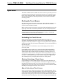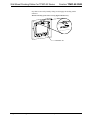
1
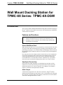
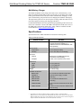
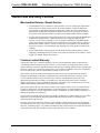
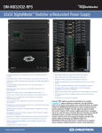
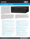
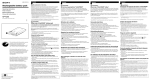
Crestron TPMC-8X-DSW Wall Mount Docking Station for TPMC-8X Series Operations & Installation Guide This document was prepared and written by the Technical Documentation department at: Regulatory Compliance As of the date of manufacture, the TPMC-8X-DSW has been tested and found to comply with specifications for CE marking and standards per EMC and Radiocommunications Compliance Labelling. Federal Communications Commission (FCC) Compliance Statement This device complies with part 15 of the FCC Rules. Operation is subject to the following conditions: (1) This device may not cause harmful interference and (2) this device must accept any interference received, including interference that may cause undesired operation. CAUTION: Changes or modifications not expressly approved by the manufacturer responsible for compliance could void the user’s authority to operate the equipment. NOTE: This equipment has been tested and found to comply with the limits for a Class B digital device, pursuant to part 15 of the FCC Rules. These limits are designed to provide reasonable protection against harmful interference in a residential installation. This equipment generates, uses and can radiate radio frequency energy and, if not installed and used in accordance with the instructions, may cause harmful interference to radio communications. However, there is no guarantee that interference will not occur in a particular installation. If this equipment does cause harmful interference to radio or television reception, which can be determined by turning the equipment off and on, the user is encouraged to try to correct the interference by one or more of the following measures: Reorient or relocate the receiving antenna Increase the separation between the equipment and receiver Connect the equipment into an outlet on a circuit different from that to which the receiver is connected Consult the dealer or an experienced radio/TV technician for help Industry Canada (IC) Compliance Statement This Class B digital apparatus complies with Canadian ICES-003. Cet appareil numérique de la classe B est conforme à la norme NMB-003 du Canada. The specific patents that cover Crestron products are listed at patents.crestron.com. Crestron, the Crestron logo, Adagio, Cresnet, Crestron e-Control, Crestron RoomView, Fusion RV, Isys and Sonnex are either trademarks or registered trademarks of Crestron Electronics, Inc. in the United States and/or other countries. Other trademarks, registered trademarks and trade names may be used in this document to refer to either the entities claiming the marks and names or their products. Crestron disclaims any proprietary interest in the marks and names of others. ©2012 Crestron Electronics, Inc. Crestron TPMC-8X-DSW Wall Mount Docking Station for TPMC-8X Series Contents Wall Mount Docking Station for TPMC-8X Series: TPMC-8X-DSW 1 Introduction ............................................................................................................................... 1 Features and Functions ................................................................................................ 1 Specifications .............................................................................................................. 2 Physical Description.................................................................................................... 3 Setup .......................................................................................................................................... 6 Ethernet ....................................................................................................................... 6 Supplied Hardware ...................................................................................................... 6 Mounting Options........................................................................................................ 6 Hardware Hookup ..................................................................................................... 10 Operation ................................................................................................................................. 11 Docking the Touch Screen ........................................................................................ 11 Undocking the Touch Screen .................................................................................... 11 Problem Solving ...................................................................................................................... 13 Troubleshooting......................................................................................................... 13 Reference Documents................................................................................................ 14 Further Inquiries ........................................................................................................ 14 Future Updates .......................................................................................................... 14 Return and Warranty Policies .................................................................................................. 15 Merchandise Returns / Repair Service ...................................................................... 15 Crestron Limited Warranty........................................................................................ 15 Operations & Installation Guide – DOC. 7080B Contents • i Crestron TPMC-8X-DSW Wall Mount Docking Station for TPMC-8X Series Wall Mount Docking Station for TPMC-8X Series: TPMC-8X-DSW Introduction The Crestron® TPMC-8X-DSW Wall Mount Docking Station facilitates charging of the Isys® TPMC-8X Series WiFi Touch Screens while simultaneously enabling full wired touch screen operation. Features and Functions • • • Docks the TPMC-8X Series touch screens Enables communication between control system and touch screen Recharges touch screen batteries while simultaneously enabling fully wired touch screen operation Secure Wall Mount Dock While docked, the touch screen is secured in place by an electronic latch. The touch screen lays flush within the docking station, providing a refined appearance while prohibiting prying fingers or an accidental bump from dislodging it. When released, the mechanism gently extends the touch screen outward, ready to be disengaged for portable use. Pass code protection can be employed on the touch screen to prevent unauthorized removal from the docking station. All functions of the docking station can also be controlled programmatically from the control system via Ethernet and through Crestron RoomView® or Fusion RV™ Software. A hardware key is provided to release the touch screen from the docking station in the case of a power failure. High Speed Connectivity On the side of the TPMC-8X-DSW, a 10/100 Ethernet port provides for direct connection to a wired LAN, allowing wired operation of the touch screen while docked in the absence of a wireless connection. Two USB ports are included to support a wired mouse and keyboard (not included). Audio Output A balanced line output allows for connection to Sonnex™, Adagio® and other multiroom audio distribution systems using CAT5 or conventional wiring. Through this connection, streaming audio content playing on the touch screen can be shared with listeners throughout the home or office. Operations & Installation Guide – DOC. 7080B Wall Mount Docking Station for TPMC-8X: TPMC-8X-DSW • 1 Wall Mount Docking Station for TPMC-8X Series Crestron TPMC-8X-DSW Multi-Battery Charger The TPMC-8X-DSW not only charges the touch screen’s internal battery, it can charge an optional external battery pack as well. In fact, it can charge one external battery pack attached to the touch screen while simultaneously charging a second spare external battery pack placed in its own charging slot within the docking bay. The spare battery pack can even be left in place to charge while the touch screen is removed, keeping one battery pack charging at all times.* For detailed information about the operation and programming of the touch screen itself, refer to the latest version of the TPMC-8X Operations Guide (Doc. 6539) or the TPMC-8X-GA Operations Guide (Doc. 7078), which are available from the Crestron Web site (www.crestron.com/manuals). Specifications Specifications for the TPMC-8X-DSW are listed in the following table. TPMC-8X-DSW Specifications SPECIFICATION Power Requirements DETAILS 75 Watts (3.13 Amps) @ 24 Volts DC; Requires dedicated CNPWS-75 or dedicated channel of C2N-SPWS300, both sold separately Environmental Temperature 41º to 122ºF (5º to 50ºC) Humidity 10% to 90% RH (non-condensing) Enclosure Chassis Metal, flush mountable (all mounting accessories sold separately) Faceplate Plastic, color matched to touch screen Dimensions Height 10.16 in (258 mm) Width 11.74 in (298 mm) Depth 3.67 in (93 mm) Weight 4.7 lbs (2.13 kg) Available Accessories * BB-8X-DSW Pre-Construction Wall Mount Back Box CNPWS-75 Cresnet Power Supply, 75 Watts MMK-8X-DSW Mud Ring PMK-8X-DSW Pre-Construction Wall Mount Kit TMK-8X-DSW Trim Ring WMKM-8X-DSW Post-Construction Wall Mount Kit with Mud Ring WMKT-8X-DSW Lectern or Post-Construction Wall Mount Kit with Trim Ring This manual is for TPMC-8X-DSW (material # 6504859), which is compatible with the TPMC-8X-GA, as well as with previous model TPMC-8X touch screens. Owners of an older model TPMC-8X-DSW who wish to use it with a TPMC-8X-GA must contact Crestron Customer Support to acquire the TPMC-8X-DSW Bezel Conversion Kit (material # 6505136). 2 • Wall Mount Docking Station for TPMC-8X: TPMC-8X-DSW Operations & Installation Guide – DOC. 7080B Crestron TPMC-8X-DSW Wall Mount Docking Station for TPMC-8X Series Physical Description This section provides information on the connections, controls and indicators available on the TPMC-8X-DSW. TPMC-8X-DSW Overall Dimensions (Front View with Bezel) 1 10.16 in (258 mm) 2 3 11.74 in (298 mm) TPMC-8X-DSW Overall Dimensions (Front View Bezel Removed) 4 7.38 in (188 mm) (4x) 0.17 in Thru (5 mm) 11.19 in (284 mm) Operations & Installation Guide – DOC. 7080B Wall Mount Docking Station for TPMC-8X: TPMC-8X-DSW • 3 Wall Mount Docking Station for TPMC-8X Series Crestron TPMC-8X-DSW TPMC-8X-DSW Overall Dimensions (Side View) 9.26 in (235 mm) 5 7.92 in (201 mm) 6 7 8 3.67 in (93 mm) 4.21 in (107 mm) 0.48 in (12 mm) TPMC-8X-DSW Overall Dimensions (Bottom View) 2.06 in (53 mm) 1.19 in (30 mm) 4 • Wall Mount Docking Station for TPMC-8X: TPMC-8X-DSW 3.21 in (82 mm) 0.44 in (11 mm) Operations & Installation Guide – DOC. 7080B Crestron TPMC-8X-DSW Wall Mount Docking Station for TPMC-8X Series Connectors, Controls & Indicators # CONNECTORS1, CONTROLS & INDICATORS 1 Power/Suspend Button 2 Charging Status LED 3 Docking Port 4 Audio Output Switch (1) Two-position switch (behind front bezel); Enables/disables AUDIO connector AUDIO (1) 5-pin 3.5 mm detachable terminal block; Balanced/unbalanced stereo line level audio output 5 + - S + - 6 USB 4 3 2 1 7 LAN Green LED Pin 8 8 Yellow LED Pin 1 PWR 24 G DESCRIPTION (1) Push button, activates the POWER/SUSPEND function on the TPMC-8X Series touch screen2 (1) Dual color LED; Orange indicates an external battery pack is charging; Green indicates battery is fully charged2 Mates with touch screen (sold separately) while docked2 (2) USB Type A female; USB 2.0 port for keyboard, mouse and storage devices (Keyboard and mouse not included) (1) 8-wire RJ-45 with 2 LED indicators; 10BASE-T/100BASE-TX Ethernet port; Green LED indicates link status Yellow LED indicates Ethernet activity PIN SIGNAL PIN SIGNAL 1 2 3 4 TX + TX RC+ N/C 5 6 7 8 N/C RC N/C N/C (1) 2-pin 3.5 mm detachable terminal block; 24 Volt DC power input; Wire size: 18 AWG maximum 1. Interface connectors for AUDIO and PWR ports are provided with the unit. 2. TPMC-8X Series touch screen and all battery packs sold separately. Operations & Installation Guide – DOC. 7080B Wall Mount Docking Station for TPMC-8X: TPMC-8X-DSW • 5 Wall Mount Docking Station for TPMC-8X Series Crestron TPMC-8X-DSW Setup Ethernet Unlike other Crestron network devices, the TPMC-8X-DSW does not use Cresnet for communications between the device and the control system. The TPMC-8X-DSW requires the use of a high-speed Ethernet connection for control system communications. For information on connecting Ethernet devices in a Crestron system, refer to the latest version of the Crestron e-Control Reference Guide (Doc. 6052). Supplied Hardware The hardware supplied with the TPMC-8X-DSW is listed in the following table. Supplied Hardware for the TPMC-8X-DSW DESCRIPTION PART NUMBER QUANTITY TPMC-8X-DSW Assembly 2030077 1 TPMC-8X-DSW Bezel 4513545 1 Screw, #06-32 x 1-1/2”, Pan, Phil 2007254 4 Screw, 3mm x 6mm 2018276 2 Rubber Cap 2029706 2 Hardware Key 2018275 1 Connector, Plug, 2-Pin, Skt, Single 2030076 1 Connector, Plug, 5-Pin, Skt, Single 2030073 1 Mounting Options The TPMC-8X-DSW Docking Station and TPMC-8X Series touch screens install simply and cleanly into existing or newly constructed walls with an assortment of pre- and post-construction mounting options. All mounting options are provided separately from the actual touch screen. Refer to the following table for a complete list of mounting options and respective Installation Guides. Mounting Options for the TPMC-8X-DSW and TPMC-8X Series Touch Screens PRE-CONSTRUCTION1 OPTION POSTCONSTRUCTION2 OPTION MODEL NUMBER DOCUMENT NUMBER Back Box Kit - BB-8X-DSW 6579 Pre-Construction Mount Kit - PMK-8X-DSW 6580 Mud Mount Kit (accessory) - MMK-8X-DSW 6581 Trim Mount Kit (accessory) - TMK-8X-DSW 6582 3 - Wall Mount Kit – Mud WMKM-8X-DSW 6581 - Wall Mount Kit – Trim WMKT-8X-DSW3 6582 1. Pre-construction refers to framed walls prior to hanging drywall. 2. Post-construction refers to framed walls with drywall hung. 6 • Wall Mount Docking Station for TPMC-8X: TPMC-8X-DSW Operations & Installation Guide – DOC. 7080B Crestron TPMC-8X-DSW Wall Mount Docking Station for TPMC-8X Series 3. Since the TPMC-8X-DSW contains moving parts, mounting to a stud offers more support and is therefore highly recommended. Although Crestron offers the post-construction WMKM-8X-DSW and WMKT-8X-DSW mounting options, a mounting option that is secured to a stud, such as the BB-8X-DSW or PMK-8X-DSW is highly recommended. NOTE: The following steps are performed only after the BB-8X-DSW or PMK-8X-DSW has been installed. It is assumed the BB-8X-DSW or PMK-8X-DSW has been secured to the stud according to the instruction in the latest Installation Guides (Doc. 6579 and Doc. 6580 respectively). It is also assumed that drywall is in place and a cutout for the TPMC-8X-DSW and touch screen is made in the drywall. If the BB-8X-DSW or PMK-8X-DSW is to be used and a TPMC-8X-DSW Docking Station is not available, the installer can either leave the hole in the mounting surface open (if permitted by local building codes) or attach the cover plate supplied with the mounting kit. TPMC-8X-DSW Mounting Tools Required: #2 Phillips tip screwdriver 1. If the cover plate is attached, use a #2 Phillips screwdriver to loosen and remove the four screws and plate. 2. Connect all required cables to the TPMC-8X-DSW. Use the provided 2-pin and 5-pin connectors for 24 Volt power and audio output respectively. Refer to “Hardware Hookup” on page 10 for details. 3. Insert the TPMC-8X-DSW (without its bezel) into the mounting option and align the four screw holes. 4. Insert and tighten the four supplied screws (finger tight and then using a #2 Phillips screwdriver, tighten an additional 1/8-turn). 5. In order for the TPMC-8X-DSW to recognize the presence of a TPMC-8X Series touch screen, a connection must be made between the TPMC-8X-DSW and the bezel. To connect the bezel, complete the following procedure: a. On the rear of the bezel’s upper right corner, locate the cable connector, as shown in the following illustration. TPMC-8X-DSW Bezel Cable Connector Operations & Installation Guide – DOC. 7080B Wall Mount Docking Station for TPMC-8X: TPMC-8X-DSW • 7 Wall Mount Docking Station for TPMC-8X Series b. Crestron TPMC-8X-DSW Slide the connector to remove it from its slot on the bezel, as shown in the following illustration. Slide Connector from Bezel c. The mating connector on the TPMC-8X-DSW is taped to the inside, as shown in the following illustration. Mating Connector Taped to Inside of TPMC-8X-DSW d. Remove the tape and connect the mating connector to the connector on the bezel, as shown in the illustration below. Connecting TPMC-8X-DSW to Bezel 8 • Wall Mount Docking Station for TPMC-8X: TPMC-8X-DSW Operations & Installation Guide – DOC. 7080B Crestron TPMC-8X-DSW Wall Mount Docking Station for TPMC-8X Series e. Slide the assembled connector back into its slot on the bezel, as shown in the illustration below. Assembled Connector in Slot on Bezel 6. To cover the mounted unit with the bezel, make sure the lip near the top of the bezel is inserted into the TPMC-8X-DSW just below the latch that locks onto the top of the touch screen. Then make sure the bottom of the bezel engages the four clips on the bottom edge of the TPMC-8X-DSW. Finally, push the top of the bezel fully into the TPMC-8X-DSW, secure it with the two supplied screws and cover the screws with the two supplied rubber caps. Refer to the following illustration. TPMC-8X-DSW Mounting Using (Optional) BB-8X-DSW Back Box – Exploded View BB-8X-DSW (sold separately) Drywall TPMC-8X-DSW Screws (4) #06-32 x 1 1/2" (2 On Each Side) Screws (2) Rubber Caps (2) TPMC-8X-DSW (Bezel Removed) 7. Clips for Bezel Bezel Touch Screen (Sold Separately) The TPMC-8X Series touch screen can now be docked. Refer to “Docking the Touch Screen” on page 11 for details. TPMC-8X-DSW Removal If it is necessary to remove the TPMC-8X-DSW after it has been installed into a mounting surface, complete the following steps in the order provided. The only tool required is a #2 Phillips tip screwdriver. 1. Undock the touch screen. Refer to “Undocking the Touch Screen” which starts on page 11 for details. Operations & Installation Guide – DOC. 7080B Wall Mount Docking Station for TPMC-8X: TPMC-8X-DSW • 9 Wall Mount Docking Station for TPMC-8X Series Crestron TPMC-8X-DSW 2. To remove the bezel from the TPMC-8X-DSW, first remove the two rubber caps covering the screws near the top of the bezel. Then remove the screws that secure the bezel to the TPMC-8X-DSW. Gently pry the top of the bezel away from the TPMC-8X-DSW and finally, lift the bezel slightly to clear the four clips on the bottom edge of the TPMC-8X-DSW. Do not apply excessive pressure. 3. To disconnect the bezel from the TPMC-8X-DSW, slide the connector on the upper right of the bezel from its slot, then disengage the connectors. (Refer to the illustration at the bottom of page 8.) 4. Loosen and remove the four screws that secure TPMC-8X-DSW to the mounting option in use. 5. Using equal pressure, carefully remove the TPMC-8X-DSW from the opening. 6. If necessary, secure and label the attached cables before disconnecting them from the side of the TPMC-8X-DSW. Hardware Hookup Make the necessary connections as called out in the illustration below. Apply power after all connections have been made. When making connections to the TPMC-8X-DSW, use Crestron power supplies for Crestron equipment. Hardware Connections for the TPMC-8X-DSW AUDIO: To Balanced/Unbalanced Stereo Line Level Inputs USB (2): Kyeboard, Mouse and Storage Devices LAN: 10BASE-T/100BASE-TX High Speed Ethernet PWR: 24 VDC Input NOTE: If the TPMC-8X-DSW is to be fed power from a Cresnet bus (the 24 and G lines), be sure that the Cresnet data lines (Y and Z) are not connected to the TPMC-8X-DSW, nor shorted together, to ground or to any metal surface. Be sure to isolate them properly and prevent them from shorting to anything. NOTE: The maximum continuous current from equipment under any external load conditions shall not exceed a current limit that is suitable for the minimum wire gauge used in interconnecting cables. The ratings on the connecting unit's supply input should be considered to prevent overloading the wiring. 10 • Wall Mount Docking Station for TPMC-8X: TPMC-8X-DSW Operations & Installation Guide – DOC. 7080B Crestron TPMC-8X-DSW Wall Mount Docking Station for TPMC-8X Series Operation The TPMC-8X-DSW docks the TPMC-8X Series touch screen, provides power and communication and recharges the internal battery and up to two (optional) external battery packs. Operation consists of docking the touch screen (performed by hand) into the TPMC-8X-DSW or undocking electrically via the touch screen and then removing by hand. Docking the Touch Screen Insert the bottom edge of the touch screen into the TPMC-8X-DSW, making sure to align the docking station connector on the bottom of the touch screen with the connector inside the TPMC-8X-DSW. Make sure the touch screen is squarely seated in the TPMC-8X-DSW, then press the upper edge of the touch screen inward, toward the wall, until it snaps into position. NOTE: The touch screen must be fully inserted into the TPMC-8X-DSW with its compact flash slot cover in place, in order for the power, audio, LAN and USB connections from the TPMC-8X-DSW to function. Undocking the Touch Screen During normal operation, the TPMC-8X-DSW unlatches the touch screen electrically using hard button #4 on the touch screen (if the default for this button is engaged) or a reserved join number is engaged or by using the Biometric fingerprint scanner on the TPMC-8X. (For location of hard button #4, refer to the illustration on the following page.) When the touch screen is unlatched, it snaps outward slightly and may then be removed by hand. If the TPMC-8X Series touch screen is released from the TPMC-8X-DSW Wall Mount Docking Station and pressed back into position within the docking station within less than eight seconds, the touch screen displays a message on the screen saying it did not release from the docking station. This message indicates the panel expected to be undocked and it is not. This message can be acknowledged and is of no concern. To avoid this message in future instances, simply allow eight seconds after undocking before pressing the panel back into the docking station. Electrical Undocking of Touch Screen Using hard button #4 on the TPMC-8X Series touch screen (if the default for this button is engaged) or a reserved join number or the Biometric fingerprint scanner on the TPMC-8X, unlatch the touch screen. Then remove the touch screen by gently pulling the upper edge of the touch screen outward (away from the TPMC-8X-DSW) and lifting it to disengage the docking station connector. Manual Undocking of Touch Screen In the event of a power failure, the touch screen can be undocked manually. This is accomplished by inserting the supplied hardware key into the opening just above the center of the touch screen and pressing downward on the key, so the inserted part lifts the latch securing the top of the touch screen into the TPMC-8X-DSW. (Refer to the illustration on the following page.) The touch screen snaps outward slightly and Operations & Installation Guide – DOC. 7080B Wall Mount Docking Station for TPMC-8X: TPMC-8X-DSW • 11 Wall Mount Docking Station for TPMC-8X Series Crestron TPMC-8X-DSW may then be removed by hand by lifting it to disengage the docking station connector. Manual Undocking of Touch Screen Using Supplied Hardware Key Hard Button #4 12 • Wall Mount Docking Station for TPMC-8X: TPMC-8X-DSW Operations & Installation Guide – DOC. 7080B Crestron TPMC-8X-DSW Wall Mount Docking Station for TPMC-8X Series Problem Solving Troubleshooting The following table provides corrective action for possible trouble situations. If further assistance is required, please contact a Crestron customer service representative. TPMC-8X-DSW Troubleshooting TROUBLE POSSIBLE CAUSE(S) CORRECTIVE ACTION TPMC-8X-DSW does not unlatch the touch screen. Touch screen is not properly docked. Adjust the touch screen to make sure it is squarely seated in the unit and fully snapped into position. TPMC-8X-DSW contacts are dirty. Perform “Manual Undocking of Touch Screen” (refer to page 11), then clean the contacts. The solenoid connector is not secure. Perform “Manual Undocking of Touch Screen” (refer to page 11), then unmount the unit (refer to “TPMC-8X-DSW Removal” which starts on page 9) and check that the connectors are secure. Touch screen does not dock in the TPMC-8X-DSW. There is mechanical binding in the TPMC-8X-DSW. Unmount the unit (refer to “TPMC-8X-DSW Removal” which starts on page 9) and check the assembly. Touch screen works in wireless mode but not when docked. TPMC-8X-DSW contacts are dirty. Perform “Manual Undocking of Touch Screen” (refer to page 11), then clean the contacts. Insufficient power from Cresnet connection. If the unit is powered via a Cresnet cable, use the Crestron Power Calculator to help calculate system requirements. (Refer to www.crestron.com/calculators). TPMC-8X Series touch screen mounted in the TPMC-8X-DSW does not recharge. TPMC-8X-DSW contacts are dirty. Perform “Manual Undocking of Touch Screen” (refer to page 11), then clean the contacts. Internal battery or external battery pack cannot retain a charge. Undock the touch screen and replace the internal battery or external battery pack. Power connection is not secure. Undock the touch screen, then unmount the unit (refer to “TPMC-8X-DSW Removal” which starts on page 9) and check that the connectors are secure. Enclosure clearance is not adjusted properly. Undock the touch screen, refer to the BB-8X-DSW or PMK-8X-DSW Installation guide* and re-adjust the enclosure clearance. Front panel is not flush with the wall. * For further information, refer to the latest revision of the BB-8X-DSW or PMK-8X-DSW Installation Guides (Doc. 6579 and Doc. 6580 respectively). Operations & Installation Guide – DOC. 7080B Wall Mount Docking Station for TPMC-8X: TPMC-8X-DSW • 13 Wall Mount Docking Station for TPMC-8X Series Crestron TPMC-8X-DSW Reference Documents The latest version of all documents mentioned within the guide can be obtained from the Crestron Web site (www.crestron.com/manuals). List of Related Reference Documents DOCUMENT TITLE TPMC-8X Operations Guide TPMC-8X-GA Operations Guide Crestron e-Control Reference Guide BB-8X-DSW Wall Pre-Construction Wall Mount Back Box PMK-8X-DSW Pre-Construction Mount Kit MMK-8X-DSW & WMKM-8X-DSW Mud Mount Kits TMK-8X-DSW & WMKT-8X-DSW Trim Ring Mount Kits Further Inquiries To locate specific information or resolve questions after reviewing this guide, contact Crestron's True Blue Support at 1-888-CRESTRON [1-888-273-7876] or refer to the listing of Crestron worldwide offices on the Crestron Web site (www.crestron.com/offices) for assistance within a particular geographic region. To post a question about Crestron products, log onto the Online Help section of the Crestron Web site (www.crestron.com/onlinehelp). First-time users must establish a user account to fully benefit from all available features. Future Updates As Crestron improves functions, adds new features and extends the capabilities of the TPMC-8X-DSW, additional information may be made available as manual updates. These updates are solely electronic and serve as intermediary supplements prior to the release of a complete technical documentation revision. Check the Crestron Web site periodically for manual update availability and its relevance. Updates are identified as an “Addendum” in the Download column. 14 • Wall Mount Docking Station for TPMC-8X: TPMC-8X-DSW Operations & Installation Guide – DOC. 7080B Crestron TPMC-8X-DSW Wall Mount Docking Station for TPMC-8X Series Return and Warranty Policies Merchandise Returns / Repair Service 1. No merchandise may be returned for credit, exchange or service without prior authorization from Crestron. To obtain warranty service for Crestron products, contact an authorized Crestron dealer. Only authorized Crestron dealers may contact the factory and request an RMA (Return Merchandise Authorization) number. Enclose a note specifying the nature of the problem, name and phone number of contact person, RMA number and return address. 2. Products may be returned for credit, exchange or service with a Crestron Return Merchandise Authorization (RMA) number. Authorized returns must be shipped freight prepaid to Crestron, 6 Volvo Drive, Rockleigh, N.J. or its authorized subsidiaries, with RMA number clearly marked on the outside of all cartons. Shipments arriving freight collect or without an RMA number shall be subject to refusal. Crestron reserves the right in its sole and absolute discretion to charge a 15% restocking fee plus shipping costs on any products returned with an RMA. 3. Return freight charges following repair of items under warranty shall be paid by Crestron, shipping by standard ground carrier. In the event repairs are found to be non-warranty, return freight costs shall be paid by the purchaser. Crestron Limited Warranty Crestron Electronics, Inc. warrants its products to be free from manufacturing defects in materials and workmanship under normal use for a period of three (3) years from the date of purchase from Crestron, with the following exceptions: disk drives and any other moving or rotating mechanical parts, pan/tilt heads and power supplies are covered for a period of one (1) year; touch screen display and overlay components are covered for 90 days; batteries and incandescent lamps are not covered. This warranty extends to products purchased directly from Crestron or an authorized Crestron dealer. Purchasers should inquire of the dealer regarding the nature and extent of the dealer's warranty, if any. Crestron shall not be liable to honor the terms of this warranty if the product has been used in any application other than that for which it was intended or if it has been subjected to misuse, accidental damage, modification or improper installation procedures. Furthermore, this warranty does not cover any product that has had the serial number altered, defaced or removed. This warranty shall be the sole and exclusive remedy to the original purchaser. In no event shall Crestron be liable for incidental or consequential damages of any kind (property or economic damages inclusive) arising from the sale or use of this equipment. Crestron is not liable for any claim made by a third party or made by the purchaser for a third party. Crestron shall, at its option, repair or replace any product found defective, without charge for parts or labor. Repaired or replaced equipment and parts supplied under this warranty shall be covered only by the unexpired portion of the warranty. Except as expressly set forth in this warranty, Crestron makes no other warranties, expressed or implied, nor authorizes any other party to offer any warranty, including any implied warranties of merchantability or fitness for a particular purpose. Any implied warranties that may be imposed by law are limited to the terms of this limited warranty. This warranty statement supersedes all previous warranties. Operations & Installation Guide – DOC. 7080B Wall Mount Docking Station for TPMC-8X: TPMC-8X-DSW • 15 Crestron Electronics, Inc. 15 Volvo Drive Rockleigh, NJ 07647 Tel: 888.CRESTRON Fax: 201.767.7576 www.crestron.com Operations & Installation Guide – DOC. 7080B (2028797) 08.12 Specifications subject to change without notice.