1
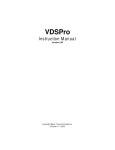
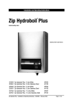
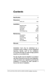
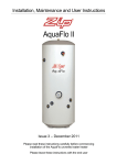
INSTALLATION &
OPERATION GUIDE
818 SPORT MODELS
Technical
Manual
818 Sport Models
Contents
1. Range Overview. . . . . . . . . . . . . . . . . . . . . . . . . . . . . . . . . . . . . . Page 4
2. Installation and Operation Guides . . . . . . . . . . . . . . . . . . . . . . Page 10
3. Sanitisation and Cleaning Guides . . . . . . . . . . . . . . . . . . . . . . Page 22
4. Troubleshooting Guides . . . . . . . . . . . . . . . . . . . . . . . . . . . . . . Page 25
5. Exploded Diagrams. . . . . . . . . . . . . . . . . . . . . . . . . . . . . . . . . . Page 32
6. Complete Parts Listing. . . . . . . . . . . . . . . . . . . . . . . . . . . . . . . Page 40
7. Appendices . . . . . . . . . . . . . . . . . . . . . . . . . . . . . . . . . . . . . . . . Page 47
Technical Manual
818 Sport
Section1
818 Sport Models
Range Overview
A range of compact countertop water dispensers, available in two different operational
types:
• 818
• 818 CS
Cold and Ambient
Cold and Sparkling
(Low Pressure Tank System)
(Direct Chill System)
Both types are available as:
• Countertop
• With optional base cabinet (Close fitting to create Floor Standing style appearance)
4
818 Sport Models
All Types
All B&O 818 Sport models are self contained machines with robust steel framed cabinets and attractively injection
moulded plastic front, side and top panels. There is sufficient space internally for most filters to be fitted behind
the right side panel.
An IEC Power Lead is supplied for connection to the IEC socket found on the rear of all models (An additional
Schuko type is supplied for the European market).
Optional Floorstanding Base Cabinet
A sturdy, steel-sided cabinet with an opening door and service access ports in the rear panel. Adjustable feet are
standard.
818 Cold and Ambient Model
Water is fed into the insulated Cold Tank under mains pressure. We strongly recommend fitting a Pressure
Reducing Valve is fitted to all supplies to regulate the pressure to 3.5 bar/355 kPa. Water bypasses the cold tank
for the ambient dispense option. The cold tank is chilled via the outer evaporation coil of the capillary controlled
refrigeration compression system.
Dispense is at inlet pressure via the DC current operated solenoid valves.
The Cold Temperature is thermostatically controlled via the adjustment screw on the back of the machine. This
setting is factory set and is not necessary to adjust in most cases (see Controls).
The Cold Tank can be drained via the lower of the two Drain Ports on the rear of the machine.
818 Cold and Sparkling Model
A Direct Chill cold water dispenser where water is used as the cooling medium in the Direct Chill tank. This is
automatically filled and controlled by the level control system upon installation. This tank is then chilled via the
outer evaporation coil of the capillary controlled refrigeration compression system.
Water is chilled as it passes through the coil immediately before dispense or being pumped under pressure into the
carbonator which it fitted inside the same coil. The carbonator is also level controlled and allows the sparkling
effect to occur through saturation with CO2.
The level control system also incorporates a leak detection device within the cabinet which switches the machine
off in the event of detecting water.
The Cold Temperature is thermostatically controlled via the adjustment screw on the back of the machine. This is
factory set and is not necessary to adjust in most cases (see Controls).
The Cold Tank can be drained via the upper of the two Drain Parts on the rear of the machine.
5
818 Sport Models
Controls
Cold & Ambient Models
On/Off switch – at upper rear of machine.
Switches Cooling Operation on/off.
Cold Thermostat – at rear of machine.
Factory set to:
-C
+C
NB: Turn clockwise to decrease water temperature
Ambient Button
Press to dispense Ambient water
Cold Button
Press to dispense Cold water
Green LED (LH)
Colours to show Cooling Operation is switched on
Green LED (RH)
Colours to show when compressor is operating/water is above set point
10A Fuse
On rear of machine, integral with IEC socket
Cold and Sparkling Models
On/Off switches – at upper rear of machine
Cold – switches Cooling Operation on/off
Soda – switches Sparkling Operation on/off
The thermostat setting is the same as for the Cold & Ambient model as above.
Sparkling Button
Press to dispense Sparkling Water
Cold Button
Press to dispense Cold Water
Green LED (LH)
Colours to show Cooling Operation is switched on
Green LED (RH)
Shows when compressor is operating
Yellow LED (bottom RH)
Colours to show the Sparkling Operation is switched on
10A Fuse
On rear of machine, integral with IEC socket
6
818 Sport Models
Base Cabinet
Either 818 model is designed to fit straight onto the top of the cabinet. Ensure the feet of the machine securely
locate in the nesting positions.
The Door Panel is hinged and fastened with Magnetic Catches. The Cabinet can be levelled using the adjustable
feet. Service entry points are positioned in the back of the cabinet.
Every Base Cabinet is supplied with a Level Sensor Kit, comprising:
•
Water Container
•
Sensor Unit (c/w 2 no. CR3032 batteries)
•
Drip Tray with Drainage Outlet
Simply exchange the Drip Trays, connect the Drainage Tubing, that is pre-fitted down the front left hand side of the
cabinet, into the top of the container and remove the transit seal from around the float shaft to enable operation.
A warning tone will sound when the water rises. Upon emptying the container, the warning tone will stop.
7
818 Sport Models
Specifications
COOLING SYSTEM
All
High efficiency compression system with capillary
control. Premium quality long life hermetic
compressor. Compact internal condenser – fan
assisted for greater efficiency. Environmentally
friendly R134A refrigerant.
818
High volume 3.5 litre stainless steel pressurised
cold tank for optimum water capacity on demand
and hygiene. Low sanitisation and maintenance.
Insulated tank for energy conservation. Large
volume output performance via high pressure
valves. Thermostatically controlled chilled water
temperature (range down to 1°C minimum).
Integrated stainless steel carbonator on sparkling
water machine option.
818 CS
3.5 litre stainless steel chiller tank with level
control containing stainless steel cold water direct
chill coil. Stainless steel carbonator tank with
independent level control fitted inside coil. High
capacity, low voltage diaphragm inlet pump.
COLD TEMPERATURE
2°C to 11°C.
THROUGHPUT PER HOUR
18 litres cold < 12°C / 16 litres sparkling <12°C.
DISPENSE
Ergonomically designed and situated light touch
sensitive controls.
MAXIMUM RUNNING
POWER CONSUMPTION
85 watt. Cold and ambient.
180 watt. Cold and sparkling.
POWER REQUIREMENTS
230 volt/50Hz supply required.
POWER SUPPLY
IEC power socket.
WATER CONNECTION
1/4
CO2 CONNECTION
1/4 inch
COUNTERTOP
DIMENSIONS
(w x d x h) 320 x 440 x 415mm
WEIGHTS
inch quick connection.
818
14.5 kg
818 CS
21.0 kg
quick connection.
8
Technical Manual
818 Sport
Section2
818 Sport Models
818 Sport
Cold and Ambient Model
Operation
Contents:
• Major Components
• Water Connection
• Operation
• Safety
• Sanitisation Guide (See section 3)
10
818 Sport Models
Major Components
Top Cover
Cold Water Tank
Ambient Water Button
Cold Water Button
Control Panel
Water Connection
Inlet Water (1/4”)
Drain Port
11
818 Sport Models
Operation
1. After connecting the water the tank will begin to fill. Put the
plug in the socket and the indicator lights will be lit. Try
pressing the cold water button to see if water comes out.
When water flows out of the dispenser, the cold power switch
may be turned on and it is ready to use. Please do not turn on
the power switch until water flows out of the machine, to avoid
damage. Allow up to one hour for minimum temperature
water. Flush through 10 litres of water.
Cold Power Switch
2. When the cold power switch is
turned on, the chilling LED will be
on. When the set temperature is
reached, the LED will go out.
Fused IEC Socket
12
818 Sport Models
3. Press the ambient water button for ambient water.
Cold Power
Indicator
Chilling System
Indicator
Cold Water Button
Ambient Water Button
4. Press the cold water button for cold water.
13
818 Sport Models
Safety
Leave a space no less than 15cm between the wall and
dispenser.
Keep the machine away from sunlight, heat and
moisture.
Be sure to use single outlet socket with correct power
voltage. Plug the power cord directly into the electrical
socket.
14
818 Sport Models
818CS
Cold and Sparkling Model
Operation
Contents:
• Major Components
• Water and CO2 Connection
• Cold Water Operation
• CO2 Bottle Installation
• Sparkling Operation
• Safety
• Leak Detection
• Sanitisation Guide (See Section 3)
15
818 Sport Models
Major Components
Top Cover
Sparkling Water Tank
Cold Water Tank
Control Panel
Water and CO2 Connection
CO2 Connector (1/4”)
Inlet water (1/4”)
Drain Port
16
818 Sport Models
Cold Water Operation
1. After connecting the water the tank will begin to fill
with water. Plug in the power and the indicator LEDs
will be on. Try pressing the cold button until the water
comes out. When water flows out of the dispenser,
the power switch may be turned on and the machine
is ready to use. Allow up to one hour for minimum
temperature water.
Cold water power
Carbonated
Water Power
Fused IEC Socket
Cold Water Indicator
2. Turn on the cold power switch and the cold water and
chilling LEDs will show. The temperature of cold
water can be set from 4°C to 10°C. When the chilling
LED is off the set temperature has been reached.
Sparkling Water Indicator
17
818 Sport Models
CO2 Bottle Installation
1. Attach the regulator to the disposable CO2 bottle, ensuring the regulator is closed.
2. Connect the assembled CO2 bottle and regulator to the machine.
CO2 Refill Tube
3. Do not open the regulator valve until the Carbonated switch has been turned on.
Carbonated Power Switch
1. After completing the water
installation, turn on the soda power
switch. When the pump switches off
open the CO2 regulator. Do not
exceed 5 bar pressure.
2. Initially please flush through
approximately 10 litres of water.
Soda Water Indicator
3. It will be necessary to leave the
machine for up to one hour for
sparkling water to develop, by
absorbing the CO2.
Soda Water Button
18
818 Sport Models
Safety
Leave a space no less than 15cm between the wall and
dispenser.
Keep the machine away from sunlight, heat and moisture.
Be sure to use single outlet socket with correct power
voltage. Plug the power cord directly into the electrical
socket.
19
818 Sport Models
Leak Detection
Notice:
This machine is equipped with a leakage detection device. When leaking is detected, the power will be cut off
automatically.
When the power has been cut off:
1. Unplug the machine, then remove the left side plate.
2. Detection probe found in the bottom front left hand corner and dry probes and machine with a dry cloth.
3. Plug in the machine to test if the leaking has stopped.
20
Technical Manual
818 Sport
Section3
818 Sport Models
Sanitisation Guide – 818 CS Water Cooler
1. Turn off incoming mains water, briefly press dispense button(s) to release internal water pressure from the
machine and remove filter.
2. Add 100 ml of a proprietary sanitisation fluid to a clean and empty service filter cartridge/dosing device and
connect into machine. Always ensure to use a reputable branded sanitisation fluid for effective action.
Please note: We recommend using a 3% Hydrogen Peroxide concentration base sanitising fluid of reputable
manufacture to the appropriate dilution ratios as supplied with the product or typically 1:30 max. (Stronger
concentrations will require larger dilution rates).
Please remember that most sanitisation fluids (including ozone) contain an active caustic/alkaline agent.
Always use responsibly and with care remembering that due to its alkaline nature unnecessary
concentrated/prolonged contact with any materials, including metals, can cause damage. Always rinse all
contact surfaces after use with clean water.
3. Turn on incoming water, allow service cartridge/doser to fill and then draw off at least 1 litre of water, using the
cold button only, for the machine to ingest the solution. Leave solution for 10 minutes inside machine for
sanitisation to take effect. During this time thoroughly clean the machine externally. For this we recommend
the use of proprietary disposable sanitisation wipes. Pay particular attention to the dispense faucet and the push
button controls. Remember to include the drip tray. If a Waste Overflow System is fitted, this may benefit from
flushing through with a small amount of dilute sanitisation fluid.
4. After a satisfactory period of time, flush the machine with at least 10 litres of clean water to clear any trace of
the sanitisation fluid. Optionally use test strips to check.
5. Turn off water and remove the service filter/doser and fit a new filter of reputable quality and suited to the site
conditions. We recommend pre-flushing the new filter to reduce any risk of any loose media in the filter
entering the solenoid valves and possibly causing a malfunction. Retain the service cartridge/doser for reuse.
6. Turn on incoming water supply and carefully ensure the thorough sanitising of the outside of the machine is
completed. Reconnect power and reset any service/filter life monitors accordingly. Ensure any hot tank inlet is
reconnected and the tank is purged of air before switching heater on again.
ALWAYS ENSURE ANY RESIDUAL AIR HAS BEEN PURGED FROM BOTH COLD AND
SPARKLING SYSTEMS AND ALL IS OPERATIONAL BEFORE LEAVING.
22
818 Sport Models
Sanitisation Guide – 818 Water Cooler
1. Turn off incoming mains water, briefly press dispense button(s) to release internal water pressure from the
machine and remove filter.
2. Add 100 ml of a proprietary sanitisation fluid to a clean and empty service filter cartridge/dosing device and
connect into machine. Always ensure to use a reputable branded sanitisation fluid for effective action.
Please note: We recommend using a 3% Hydrogen Peroxide concentration base sanitising fluid of reputable
manufacture to the appropriate dilution ratios as supplied with the product or typically 1:30 max. (Stronger
concentrations will require larger dilution rates).
Please remember that most sanitisation fluids (including ozone) contain an active caustic/alkaline agent.
Always use responsibly and with care remembering that due to its alkaline nature unnecessary
concentrated/prolonged contact with any materials, including metals, can cause damage. Always rinse all
contact surfaces after use with clean water.
3. Turn on incoming water, allow service cartridge/doser to fill and then draw off at least 1 litre of water for the
machine to ingest the solution. Leave solution for 10 minutes inside machine for sanitisation to take effect.
During this time thoroughly clean the machine externally. For this we recommend the use of proprietary
disposable sanitisation wipes. Pay particular attention to the dispense faucet and the push button controls.
Remember to include the drip tray. If a Waste Overflow System is fitted, this may benefit from flushing through
with a small amount of dilute sanitisation fluid.
4. After a satisfactory period of time, flush the machine with at least 10 litres of clean water to clear any trace of
the sanitisation fluid. Optionally use test strips to check.
5. Turn off water and remove the service filter/doser and fit a new filter of reputable quality and suited to the site
conditions. We recommend pre-flushing the new filter to reduce any risk of any loose media in the filter
entering the solenoid valves and possibly causing a malfunction. Retain the service cartridge/doser for reuse.
6. Turn on incoming water supply and carefully ensure the thorough sanitising of the outside of the machine is
completed. Reconnect power and reset any service/filter life monitors accordingly. Ensure any hot tank inlet is
reconnected and the tank is purged of air before switching heater on again.
ALWAYS ENSURE ANY RESIDUAL AIR HAS BEEN PURGED FROM BOTH COLD AND
AMBIENT SYSTEMS AND ALL IS OPERATIONAL BEFORE LEAVING.
23
Technical Manual
818 Sport
Section4
818 Sport Models
8 1 8
M O D E L S
O N L Y
Trouble Shooting Fault Diagnosis Guide 1
No Water Dispenses
Problem/
Report
Possible Cause
Suggested Action
No Water Dispenses
From Ambient
Valve
Water Supply turned off
(818 Cold &
Ambient only)
No Electricity/Power Supply Check power cord connected and live and
machine is switched on.
“Waterblock” tripped off
(and Tank empty)
Check all Taps/valves/ filters on incoming
supply are fitted and are turned on.
Reset “Waterblock” (and check for any
leaks).
Check valve action. Carefully dismantle valve
and clean out/part replace/complete replace
as needed.
Faulty Solenoid Valve
Valve clicking but no water-Check if hole in
centre of washer is clear.
Valve not clicking-Check whether voltage is
present when operated (Caution-High
Voltage). If not present check wiring for
continuity and /or replace PCB.
If present, replace solenoid coil/whole valve
coil/whole valve assembly complete.
From Cold Valve
25
Firstly all as for Ambient
Tap
Carry out checks and actions as for ambient
tap.
Chiller tank frozen - Faulty
Thermostat
Thaw out and check and replace Cold Water
temperature set point.
Chiller tank Frozen-faulty
air pump (818CS only)
Thaw out and check and replace Air pump
and or check electricity supply to pump
present.
Leak detector has switched
the machine off (818CS
only)
Check for internal leakage, ensure probes
are dry and switched off briefly and on again
to reset.
818 Sport Models
8 1 8
M O D E L S
O N L Y
Trouble Shooting Fault Diagnosis Guide 2
No Water Dispenses continued
No Water Dispenses continued
From Ambient
or Cold Valve
From Sparkling
Valve
Button not being pressed
enough
Press button firmly N.B. This could be
caused by a surrounding cold environment
making the action stiffer
Faulty PCB
Replace PCB
Firstly as for Ambient and
or Cold Dispense
Carry out the checks and actions as for
Ambient Dispense
Low or no CO2
Check and replace cylinder as necessary
Pump not operating
Check carbonator level Control Systems
Check probes connected/leads attached.
Check power supply to pump
Carbonator Tank over
pressurised with CO2
Switch Sparkling System off, shut off CO2
supply and release CO2 from carbonator.
Switch Sparkling system on the check pump
operation. If normal Open CO2 supply after
pump has stopped.
26
818 Sport Models
8 1 8
M O D E L S
O N L Y
Trouble Shooting Fault Diagnosis Guide 3
Water Dispenses but Not Correct Temperature
Problem/
Report
Possible Cause
Suggested Action
Water Dispenses But Not Correct Temperature
Ambient Water
too warm (818
only)
Low usage and / or fed from Advise user replacing external causes and
water supply pipe in warm
solutions.
ducting.
Cold water not
Cold
Cooling and or Sparkling
System switched off.
Check switch positions as necessary.
Compressor runs and
switching off (cool/warm to
touch )- Thermostat set too
high.
Decrease Cold Thermostat set point.
Faulty Thermostat.
Replace Thermostat
Compressor runs but not
See Appendix-Technical Advice to diagnose.
Switching off (Hot to touch).
Refrigeration problem.
27
Compressor not running at
all.
Check and replace if necessary.
No electricity power supply.
Check power cord connected and live, and
machine is switched on.
Compressor only hums
slightly/ briefly.
Check and replace relays.
Relays loose.
Check and refit relays.
Compressor Faulty.
See Appendix-Technical Advice to diagnose.
818 Sport Models
8 1 8
M O D E L S
O N L Y
Trouble Shooting Fault Diagnosis Guide 4
Water Leaks
Problem/
Report
Possible Cause
Suggested Action
Water lying on
top edge of
lower door
panel and / or
bottom of
Cabinet.
Overflowing Drip
Tray/Waste Container.
Empty Drip Tray
Water lying in
bottom of
machine
Faulty Level Sensors.
Check Batteries.
Leak in supply inlet pipework and / or filter.
Locate and repair accordingly.
Leak from machine water
pipe work fittings.
Locate and repair accordingly.
Water Leaks
Check pressure and fit pressure reducing
valve if needed.
28
818 Sport Models
8 1 8
M O D E L S
O N L Y
Trouble Shooting Fault Diagnosis Guide 5
Miscellaneous
Problem/
Report
Possible Cause
Suggested Action
Bleeping Noise
Level Sensor fitted and
Tank full.
Empty Level Sensor Tank.
No LED Lights
No electricity to Machine.
Check power supply and reconnect as
necessary (Also check out other symptoms
as described separately).
Check Fuse in IEC Socket.
Replace if necessary.
Faulty PCB (Machine
working normally
otherwise).
Replace PCB.
Miscellaneous
Machine shakes Compressor Starting.
on Start-Up
Level Surface.
Tripping out
Electricity
supply
No action needed. This is quite normal.
Uneven Surface.
Level up machine When installed with Base
Cabinet.
Missing Fixings.
Replace missing fixings.
Machine in high humidity
environment.
Discuss possible repositioning with
customer.
Electrical circuitry faults.
Test, identify and address accordingly.
See Electrical Diagrams.
(Contact Azure Technical Support for further
advice).
29
818 Sport Models
8 1 8
M O D E L S
O N L Y
Trouble Shooting Fault Diagnosis Guide 6
Miscellaneous
Problem/
Report
Possible Cause
Suggested Action
Slow but Continuous Water Dispense
From Ambient
or Cold Water
Valve
Low incoming Water
pressure.
Consider re-plumbing to alternative supply
if possible.
From Sparkling
Water Valve
Low/no CO2 Pressure.
Fit Booster Pump Set.
Check Regulator and or replace cylinder.
Intermittent Water Dispense
From Ambient
or Cold Water
Valve
From Ambient
or Cold Water
Valve and
hammering
noise
Trapped air in pipe work
(especially where water
pressure is low or after
filter change).
Hold button on to purge air out. (This could
take several minutes where pressure is low).
Button Not being pressed
enough.
Press button firmly N.B. This could be
caused by a surrounding cold environment
making the action stiffer.
Faulty PCB
Replace PCB.
Fluctuating mains water
pressure situation.
Contact Azure Technical Support regarding
special replacement washers available.
Pre-flush filters.
Continuous Water Dispense
From Ambient
or Cold Water
Valve
Button jammed on/faulty.
Replace PCB and or/ button Panel as needed.
Debris blocking hole in
diaphragm washer.
Dismantle Valve and clean out.
30
Technical Manual
818 Sport
Section5
818 Sport Models
Exploded Component Diagram 1
Borg & Overström Sport
CW818 Cold & Ambient
Exploded Component Diagram
Model No-818
32
818 Sport Models
Exploded Component Diagram 2
Borg & Overström Sport
CS818 Cold & Sparkling
Exploded Component Diagram
Model No-818
33
818 Sport Models
Parts Diagram
B19
B16
B14
B15
B5
B12
B4
B17
B1
B6
B2
B18
B9
B10
B7
B11
B11
L1
B3
B9
B10
Borg & Overström Sport
828 Base Cabinet
Parts Diagram
Model No 828-01
B12
B8
B13
34
Compressor
white
Cold Power
Switch
Fan
blue
yellow
white
white
bridge
diode
solenoid
valve
purple
white
brown
purple
I C Board
CO2 Pump
DC
white
Transformer
AC
Level Sensor
white
AC
Borg & Overström 818CS
Cold & Sparkling
Electrical Circuit Diagram
(Series-01)
brown
brown
IN
yellow
yellow
yellow
yellow
Cold Solenoid
Valve
temperature black
switch
black
blue
blue
yellow
black
black
Carbonated
Solenoid Valve
fuse
Electrical Circuit Diagram 1
818 Sport Models
35
Carbonated
Power
Switch
brown
Compressor
white
Ambient Solenoid Valve
blue
Cold Solenoid Valve
Cold Power
Switch
Temperature
Switch
blue
blue
black
black
brown
36
brown
yellow
yellow
white
blue
yellow
yellow
Electrical Circuit Diagram 2
Fuse
brown
brown
IC Board
Borg & Overström CW818
Cold & Ambient
Electrical Circuit Diagram
(Series-01)
brown
yellow
818 Sport Models
IN AC
818 Sport Models
Water Pathway Diagram 1
CO2 Input
Level Control Module
Carbonated
Water Tank
Cold Tank
Checking
Valve
Water In
Low (Y)
Bottom Plate
Full (r)
Common (B)
Inlet Solenoid Valve
Carbonated Water Solenoid
Valve
Faucet
Circulating Pump
Cold Water Solenoid Valve
Inlet Solenoid Valve
Drainage
Checking Valve
Soda Pump
Borg & Overström
818CS Cold & Sparkling
Water Pathway Diagram
(Series – 01)
Azure UK
37
818 Sport Models
Water Pathway Diagram 2
Water In
Cold Water
Cold Water
Vent
Ambient Water
Ambient Water Solenoid Valve
Faucet
Cold Water Tank
Grit Filler
Drainage Water
Grit Filler
Cold Solenoid Valve
Borg & Overström
CW818 Cold & Ambient
Water Pathway Diagram
(Series – 01)
Azure UK
38
Technical Manual
818 Sport
Section6
818 Sport Models
Quantity
Exploded component
view reference
818
Azure Part
No
Azure Ref
123185
Top Panel Black
1
P1
120815
Front Panel-Silver
1
P2
126826
Keypad Panel - Black
1
P3
124851
Bottom Panel - Black
1
P4
125831
Drip Tray set
1
P5
132449
Single check Valve
1
P6
121055
Left Side Panel-Black
1
P7
121856
Right Side Panel - Black
1
P8
121859
Side Handle-Silver
2
P9
133513
Faucet
1
P10
131422
Faucet Back Nut
3
P11
131643
1/4" Stem Elbow
5
P12
131426
Twin Drainage Port
1
P13
131642
1/4" Push Fit Inlet Elbow
1
P14
131641
1/4" Push Fit Inlet Connector
2
P15
131647
1/4" Push Fit Elbow
2
P16
174312
PCB Rear Cover
1
P17
194412
1/4" Grit Filter
1
P18
131648
1/4" Push Fit Y Joint
1
P19
134591
PVC Pipe Sleeving
3
P20
131649
1/4" Push Fit Tee
2
P21
134592
1/4" LLDPE Water Pipe
9
P22
134561
Dispense Tube -Large
2
P23
135718
Pipe Insulation
1
P24
127851
Top Frame
1
M1
127852
Front Frame Support
2
M2
127853
Front Frame Crossmember
1
M3
184621
Solenoid Mounting Bracket
1
M4
122836
Back Panel
1
M5
181121
3.0 x 8 RHD S/T Screw
4
M6
181126
4.0 x 12 RHD s/T Screw
#
M7
1811127
5.0 x 10 RHD S/T Screw
4
M8
181691
4.0 x 8 RHD S/D Screw
#
M9
181124
4.0 x 12 S ?S S/T Screw
6
M10
134603
Copper Tubing
1
M11
182371
M4 x 7 YP PHD M Screw
2
M12
40
CW
CS
828
818CS
818CW
828
818 Sport Models
Quantity
Exploded component
view reference
818
Azure Part
No
Azure Ref
134602
Copper Tubing
1
M13
181342
4.0 x 20 YP PHD S/T Screw
4
M14
174316
Dryer
1
M15
134604
Copper Tubing
1
M16
181128
3.5 x 18 BA RHD S/T Screw
2
M17
181129
4.0 x 12 s/s RHD S/T Screw
1
M18
171222
PCB-Cold & Sparkling
1
E1
174313
Compressor
1
E2
173262
Cold Thermostat
1
E3
174231
Elec Rocker Switch
2
E4
173248
Solenoid Valve
4
E5
172152
UK IEC Power Cord Set
1
E6
174351
Cooling Fan
1
E7
174331
Condenser
1
E8
172164
Main Wiring Loom
1
E9
172163
IEC Socket -Fused
1
E10
172176
Blue LED Lighting
1
E11
173311
Level Control Module
1
E12
172166
Control Wiring Loom
1
E13
165240
Cold Tank Set (Complete)
1
C1
184421
Top Bracket-Rear
1
C2
184222
Top Bracket-Front
1
C3
133423
Cold Tank Lid-Outer
1
C4
134601
DC Cold Coil
1
C5
131642
1/4" Push fit Inlet Elbow
2
C6
462739
1/4" Clip
2
C7
131641
1/4" Push Fit Inlet Connector
1
C8
183423
Large Back Nut
3
C9
174341
Thermostat Sleeve
1
C10
133421
Cold Tank Coller
1
C11
135732
Cold Tank Insulation -Top
1
C12
135731
Cold Tank Insulation
1
C13
131651
Cold Tank Outlet
1
C14
168181
Carbonator Tank
1
C15
174380
Diaphragm Pump
1
C16
181125
4.0 x 16 S/S RHD S/T Screw
8
C17
CW
CS
828
818CS
818CW
828
41
818 Sport Models
Quantity
Exploded component
view reference
818
Azure Part
No
Azure Ref
174310
DC Tank Pump Set
1
C18
131581
Thermostat Sleeve Cap
1
C19
132448
Single Check Valve
2
C20
181131
4.0 x 25 RHD S/T Screw
3
C21
131643
1/4" Stem Elbow
5
C22
131652
1/4" x 3/8" Male Thread Elbow
2
C23
174385
Pump power Pack
1
C24
184619
Pump Power Pack Bracket
1
C25
181132
4.0 x 12 RHD S/T Screw
2
C26
181133
3.2 x 32 RHD S?T Screw
2
C27
173271
Level Sensor Probe
3
C28
Duplicate
1/4" LLDPE Water pipe
3
C29
Duplicate
Pipe Insulation
2
C30
135722
Pipe Insulation
1
C31
131569
Cold Tank outlet Seal
1
C32
134609
Capillary Tube
1
C33
134593
DC Coil Extension Tube
1
C34
131431
Pipe Clip
1
C35
131427
DC Tank Pump Connector
1
C36
134587
Connector Elbow
1
C37
131582
Tank Lid Bung
1
C38
172181
Keypad membrane
1
O1
135717
Insulation Sleeve
1
O2
123185
Top Panel-Black
1
P1
120815
Front Panel -Silver
1
P2
126826
Keypad Panel-Black
1
P3
124851
Bottom Panel-Black
1
P4
125831
Drip Tray Set
1
P5
132449
Single Check Valve
1
P6
121855
Left side Panel-Black
1
P7
121856
Right Side Panel-Black
1
P8
121859
Side Panel Silver
2
P9
133514
Faucet
1
P10
131422
Faucet Back Nut
2
P11
131643
1/4" Stem Elbow
3
P12
131426
Twin drainage Port
1
P13
42
CW
CS
828
818CS
818CW
828
818 Sport Models
Quantity
Exploded component
view reference
818
Azure Part
No
Azure Ref
131581
Faucet Bung
1
P14
131641
1/4" Push fit inlet Connector
2
P15
134565
Dispense Tube-Large
1
P16
174312
PCB Rear Cover
1
P17
194121
1/4" Grit Filter
1
P18
131649
1/4" Push fit Tee
1
P19
134592
1/4" LLDPE Water pipe
3
P20
131649
1/4" Push Fit Elbow
1
P21
127851
Top Frame
1
M1
127852
Front Frame Support
2
M2
127853
Front Frame Crossmember
1
M3
184621
Solenoid Mounting Bracket
1
M4
122836
Back Panel
1
M5
181121
3.0 x 8 RHD S/T Screw
4
M6
181126
4.0 x 12 RHD S/T Screw
#
M7
181127
5.0 x 12 RHD S/T Screw
4
M8
181681
4.0 x 8 BA RHD S/T Screw
#
M9
181124
4.0 x 12 s/s RHD S/T Screw
6
M10
134606
Copper Tubing
1
M11
182371
M4 x 7 YP PHD S/T Screw
2
M12
134602
Copper Tubing
1
M13
181342
M4 x 20 YP PHD S/T Screw
1
M14
174316
Dryer
2
M15
134604
Copper Tubing
1
M16
171221
PCB-Cold and Ambient
1
E1
174313
Compressor
1
E2
173262
Cold Thermostat
1
E3
174231
Elec Rocker Switch
1
E4
173248
Solenoid Valve
2
E5
172152
UK IEC Power Cord Set
1
E6
174351
Cooling Fan
1
E7
174331
Condenser
1
E8
172165
Main Wiring Loom
1
E9
172613
IEC Socket -Fused
1
E10
172177
Blue LED Lighting
1
E11
165250
Cold Tank Set (Complete)
1
C1
CW
CS
828
818CS
818CW
828
43
818 Sport Models
Quantity
Exploded component
view reference
818
Azure Part
No
Azure Ref
184422
Top Bracket-Front
1
C3
133424
Cold Tank Lid
1
C4
134564
Dispense Tube
1
C5
135732
Cold Tank Insulation -Top
1
C6
135731
Cold Tank Insulation
1
C7
133421
Cold Tank Coller
1
C8
183423
Large Back Nut
1
C9
174341
Thermostat Sleeve
1
C10
134605
Capillary Tube
1
C11
131581
Thermostat Sleeve Cap
1
C12
181125
4.0 x 16 S/S RHD S/T Screw
8
C13
131569
Cold Tank Outlet Seal
1
C14
131651
Cold Tank Outlet
1
C15
134592
1/4" LLDPE Water Pipe
3
C16
131649
1/4" Push Fit Tee
1
C17
134566
Vent Tube
1
C18
135722
Pipe Insulation
1
C19
135722
Pipe Insulation
1
C20
191161
PCB - Cold & Ambient
1
O1
135722
Pipe Insulation
1
O2
172148
Euro IEC Power Cord Set
1
1
User Manual
1
1
128981
B & O Carton
1
1
128904
Polybag
1
1
193221
CO2 Regulator
0
1
120821
Front Infill Panel-Black
1
B3
184542
Spring Cap
1
B6
184543
Cup Retaining Ring
1
B5
184544
Spring Base Plate
1
B8
120932
Cup Dispenser Top Panel-Black
1
B4
184545
Spring
1
B3
120816
Door Panel-Silver
1
B2
184622
Door Magnetic Catch
2
B9
131341
3.0 x 10 BZP UK S/T Screw
2
B10
181341
3.0 x 8 YP PHD S/T Screw
6
B11
181134
4.0 X 12 BZP PHD S/T Screw
5
B12
44
CW
CS
828
818CS
E6
818CW
828
E6
818 Sport Models
Quantity
Exploded component
view reference
818
Azure Part
No
Azure Ref
184532
Adjustable Foot
4
B13
184411
Grommet
2
B14
182374
3.5 x 10 YP RHD S/D Screw
1
B15
Cabinet
1
B1
193186
Level sensor (Complete)
1
L1
131568
Drain Connector
1
B16
184641
Drain Tube Fastener
1
B17
134571
Drain Tube Fastener
0
0
1
B18
125833
Drip Tray (Only) c/w Drainage
0
0
1
B19
171231
Level Sensor PCB
CW
CS
828
818CS
818CW
828
-1
174309
Level Sensor Enclosure
-1
174308
Level Sensor Float Valve
-1
193187
Level Sensor Container (Only)
-1
193222
CO2 Regulator & Gauge
-1
193323
CO2 Adaptor
-1
Adaptor Washer
-1
45
Technical Manual
818 Sport
Section7
818 Sport Models
Azure Technical Advice
If the Compressor does not run:
1. Check the LED display. For Cold & Ambient models the green (top) LED should always be on and the Yellow
(Bottom) when cooling is called for. If the green is off then check the machines main power supply and the
on/off switch.
For the Hot & Cold models the green (top) LED should always be on. If off, check the machines main power
supply and the COLD on/off switch.
2. Switching on the Compressor measure the current draw. No operation, but a high draw indicates a jammed
compressor (contact Azure Technical Support).
3. The wiring loom can be traced and the live supply check periodically moving towards the compressor (if there is
a break at the Cold Thermostat turn the screw clockwise and check whether this closes the circuit. If this
doesn’t even when at max, the thermostat should be replaced. Alternatively, for testing purposes only, the
thermostat could be bridged).
4. Remove the compressor relay cover and carefully remove the relays. If the power has been even recently
connected to the compressor, the solid stat relay will be energised and will need discharging.
5. Check the Compressor resistance readings
R
S
C
Approx readings could be:
R-C 12ohms
S-C 34ohms
R-S 46 Ohms (sum of both)
N.B. There should always be some variation between compressors. What should be identified is large
discrepancies/unbalanced readings.
Also, especially in the case of large discrepancies/unbalanced readings, check for continuity between any of the
terminals and the compressor casing. A current will indicate a shorted winding (Contact Azure Technical
support).
6. Checking the relays:
Caution: Ensure the larger relay is discharged if recently energised. (This can be discharged by 2MR, 2W
resister in the circuit).
Clearly, the best and surest way to test the relays is to replace them one by one and check the compressor
operation. Otherwise, each relay component can be basically tested using a meter
The Solid State Relay should read approx
The Klichson (overload) should read approx
3-6 closed circuit
3 ≈ 36 Ω (Ohms)
≈ 1.7Ω (Ohms)
7. Ensure the terminals are clean and good contact is made.
47
818 Sport Models
If the Compressor Does Run
(Presuming that the Cold water is not being cooled sufficiently)
1. Check the small pipe on the ‘high’ side of the compressor. This should be quite warm after several minutes of
normal operation.
2. Following it to the condenser, check the condenser temperature. Normally the beginning will be warmer,
cooling off towards the end.
• No or very low temperature could indicate a low refrigerant charge. A low current draw would indicate this.
(Contact Azure Technical Support)
• An overly high temperature could indicate a blockage; A high current draw would confirm this. (Contact
Azure Technical Support).
3. Continue to follow the pipe work from the end of the condenser to the dryer.
• A frozen / iced dryer will indicate a blockage (Contact Azure Technical Support) Again; a high current draw
would confirm this.
4. The dryer exits into the capillary tube. Check this for restrictions and NB: This has a very small bore.
5. The Capillary enters the evaporator. This can be checked visually for any obvious signs of deterioration.
6. The evaporator connects back to the ‘low’ side of the Compressor via the suction pipes. Check this for excessive
icing.
Excessive icing could indicate a refrigerant overcharge (Contact Azure Technical Support).
48
818 Sport Models
49
818 Sport Models
50
Notes
Notes
Notes
Notes
INSTALLATION & OPERATION GUIDE
818 SPORT MODELS
Technical Support
Available 0700-1700 Monday to Friday
Telephone
01362 656926
Fax
01362 656923
Email
[email protected]
Azure UK
5 John Goshawk Road
Rash's Green
East Dereham
Norfolk NR19 1SY
t +44 (0) 1362 656 928
f +44 (0) 1362 656 920
e [email protected]
w www.azureuk.co.uk