1
EB 20/110
EB 40/160
EB 60/160
EB 75/185
EB 90/185
SIDE-POWER
Thruster Systems
Installation and user's manual
N
Installasjons og brukermanual
is rd
th a
p bo
ee n
K al o
u
an
m
GB
S
S
S
S
S
!
EB 40
EB 60/75/90
SLEIPNER MOTOR AS
P.O. Box 519
N-1612 Fredrikstad
Norway
Tel: +47 69 30 00 60
Fax: +47 69 30 00 70
w w w. s i d e - p o w e r. c o m
s i d e p o w e r @ s l e i p n e r. n o
Made in Norway
EB 20
© Sleipner Motor AS February 2014
Contents
GB
Installation instructions
Technical specifications.............................................................. 3
Planning & important precautions.............................................. 4
Tunnel installation
Positioning of the tunnel / thruster ............................................. 5
How to shape the tunnel ends.................................................... 6
Prevent drag from tunnel............................................................ 7
Possible tunnel installation in sailboats...................................... 8
Tunnel installation................................................................. 9-10
Thruster installation
Thruster installation............................................................. 11-12
Propeller installation................................................................. 13
Electrical installation........................................................... 14-15
Control panel and control-leads .............................................. 16
"Visual" wiring diagrams..................................................... 17-18
Technical wiring diagrams.................................................. 19-20
Checklist .................................................................................. 21
Important user precautions....................................................... 22
User's manual
Important user precautions....................................................... 22
How to use Sidepower thrusters.............................................. 23
Maintenance & service............................................................. 24
Troubleshooting........................................................................ 25
Warranty statement ............................................................... 27
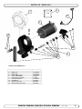
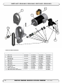
Spareparts list & drawing ............................................... 28-29
Service centres ...................................................................... 30
DECLARATION OF CONFORMITY
We, Sleipner Motor AS
P.O. Box 519
N-1612 Fredrikstad, Norway
declare that this product with accompanying
standard remote control systems complies with
the essential health and safety requirements
according to the Directive 89/336/EEC of 23
May 1989 amended by 92/31/EEC and
93/68/EEC.
Innhold
N
Installasjons instruksjoner
Tekniske spesifikasjoner..............................................................3
Planlegning og viktige forbehold.................................................4
Tunnel installasjon
Plassering av tunnel/thruster.......................................................5
Utforming av tunnelåpninger.......................................................6
Motstand forårsaket av tunnel.....................................................7
Forslag til tunnelinstallasjon på seilbåt........................................8
Tunnel installering................................................................. 9-10
Thruster installasjon
Montering av Thruster..........................................................11-12
Propeller installation..................................................................13
Elektromotor........................................................................ 14-15
Kontrollpanel og kontrollkabler..................................................16
"Visuelle" koblingsskjemaer................................................. 17-18
Koblingsskjema................................................................... 19-20
Sjekkpunktliste..........................................................................21
Brukermanual
Viktige brukerforbehold..............................................................22
Hvordan bruke Sidepower thruster............................................23
Vedlikehold................................................................................24
Problemer og løsninger.............................................................26
Garantierklæring ....................................................................27
Reservedelsliste ............................................................... 28-29
Servicesentere ....................................................................... 30
Samsvars erklæring
Sleipner Motor AS
Postboks 519
N-1612 Fredrikstad, Norge
Erklærer at dette produktet med tilhørende
standard kontrollsystemer er i samsvar med
helse, og sikkerhetskravene i henhold til Direktiv 89/336/EEC FRA 23 Mai 89, korrigert av
92/31/EEC og 93/68/EEC.
2
EB 20/110 S - EB 40/160 S - EB 60/160 S - EB 75/185 S - EB 90/185 S
1.0.6 - 2014
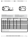
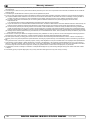
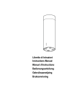
Measurements EB Series
EB20
EB40
EB60
EB75
EB90
A
Model
197 • 7.8
270 • 10.63
310 • 12.25
310 • 12.25
310 • 12.25
B
158 • 6.25
150 • 6.0
150 • 6.0
150 • 6.0
150 • 6.0
C
106 • 4.2
120 • 4.75
130 • 5.15
130 • 5.15
130 • 5.15
D
29 +/-5 • 1.15 +/- 0.2
15+/-8 • 0.6 +/- 0.32
15+/-8 • 0.6 +/- 0.32
50+/-8
50+/-8
E
180 • 7.1
192 • 7.6
192 • 7.6
200 • 7.9
200 • 7.9
F
135 • 5.32
198 • 7.8
210 • 8.3
210 • 8.3
210 • 8.3
G
136 • 5.36
65,5 • 2.6
65,5 • 2.6
75 • 3.0
75 • 3.0
H
110 • 4.34
160 • 6.3
160 • 6.3
185 • 7.3
185 • 7.3
I
286 • 11.3
230 • 9.1
J
248 • 9.8
K
130,5 • 5.12
L
24,5 • 0.95
M
25 • 0.99
N
120 • 4.73
Measurements in mm • in
EB 20
6
5
4
3
2
EB 40/45o
1
F
A
D
D
B
C
I
G
C
D
C
H
B
B
E
Designed by
Copyright All rights reserved
6
5
4
6
EB 40/90o
Date
Material Type
3
5
6
A
5
D
A
Title
3
4
SLEIPNERMOTORAS
F
3
D
Part nr
Tolerance NS-ISO 2768-1
A
XF 40R 12V
1
EB 40/60 VIEWS FOR CATALOGUE
2
4
Drawing nr
29.11.2013 SM-104534
gille
A
2
Weight
EB40/160S
2
Size
Scale
A3
20,643 kg
1
Edition
1
1
F
Sheet
1/1
D
D
G
B
C
I
B
C
G
C
C C
D
D
C
H
B
B
E
Designed by
Copyright All rights reserved
gille
Copyright All rights reserved
6
5
4
5
6
6
5
3
Material Type
Title
SLEIPNERMOTO
RAS
SLEIPNERMOTORAS
4
A
5
3
4
3
A4
Drawing nr
Tolerance NS-ISO 2768-1
29.11.2013 SM-104897
Title Date
Drawing nr
EB 75/90 VIEWS FOR CATALOGUE
XF 40R 12V
Weight
Size
Scale
A
Edition
2EB90/12V
1 1
2
EB 40/60
VIEWS
FOR
31,183
kg CATALOGUE
A3
1
2
Part nr
Weight
F
Size
20,643 kg
A
Tolerance NS-ISO 2768-1
XF90R 12V
29.11.2013 SM-104534
Part nr
EB40/160S
F 2
3
D
D
Date
Material Type
gille
Designed by
A
6
B
E
A
EB 60
A
B
1
Scale
Edition
Sheet
1/1
1
1
A3
Sheet
1/1
D D
G
B
C
I
B
C
G
C
C
C
D
D
C
A
H
B
B
B
B
E
E
Designed by
Copyright All rights reserved
6
5
4
6
5
4
A
Designed by
3
gille
Copyright All rights reserved
A
4
SLEIPNERMOTORAS
G
3
Tolerance NS-ISO 2768-1
A
XF90R 12V
Date
nr
Tolerance
EB 75/90Drawing
VIEWS
FOR CATALOGUE
2
1
SM-104534
29.11.2013
NS-ISO 2768-1
Weight
Part nr
Size
Scale
Edition
EB90/12V
XF31,183
40Rkg12VA3
1
2 F VIEWS FOR CATALOGUE 1
EB 40/60
Weight
Part nr
EB40/160S
2
Size
20,643 kg
Scale
Edition
1
1
A3
Sheet
1 / 1A
Sheet
1/1
D
C
5
Title
3
D
6
Drawing nr
29.11.2013 SM-104897
Title
Material Type
SLEIPNERMOTORAS
B
C
C
D
EB 75 / EB 90
Date
Material Type
gille
A
A
B
B
E
Designed by
Material Type
gille
A
Copyright All rights reserved
SLEIPNERMOTORAS
6
5
4
3
Date
Drawing nr
29.11.2013 SM-104897
Title
Tolerance NS-ISO 2768-1
A
XF90R 12V
EB 75/90 VIEWS FOR CATALOGUE
Part nr
EB90/12V
2
Weight
31,183 kg
Size
A3
Scale
Edition
1
1
Sheet
1/1
EB 20/110 S - EB 40/160 S - EB 60/160 S - EB 75/185 S - EB 90/185 S
1.0.6 - 2014
3
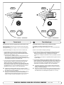
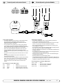
Technical specifications
N
Motor:
Custom made reversible DC-motor.
Gearhouse
/Motor bracket:
Seawateresistant Stainless steal. EB20 syntetic
material Ball bearing at propeller shaft.
Tunnel:
Cross spun with rowing G.R.P tunnel.
Motor:
Propeller:
4-blade design, reinforced acetal.
Batteries:
Minimum recommended battery capacity (cold
crank capacity by DIN/SAE standard)
EB20/110S: -12V: 200 CCA DIN/380 CCA SAE
EB40/160S: -12V: 300 CCA DIN/570 CCA SAE
EB60/160S: -12V: 350 CCA DIN/665 CCA SAE
EB60/160S: -24V: 175 CCA DIN/380 CCA SAE
EB75/185S: -12V: 500 CCA DIN/950 CCA SAE
EB75/185S : -24V: 250 CCA DIN/475 CCA SAE
EB90/185S: -12V: 500 CCA DIN/950 CCA SAE
EB90/185S: -24V: 250 CCA DIN/475 CCA SAE
Max. use: S2 = 3 min. or approx. 7-10% within a limited time frame.
Safety:
Electronic time-lapse device protects against sudden change of drive direction. Electric thermal cut-off switch in electromotor protects against over heating (auto reset when electro motor cools down). Hearpin on propeller
driveshaft protects electromotor and gear system if
propeller gets jammed.
If original Sidepower panel is used, the panel shuts off automatically 6 minutes after last use.
Integrated microprocessor monitors solenoids, reducin
wear and risk of solenoid lock-in. Autostop of thruster in case of accidental solenoid lock-in or if run signal is con-
tinuous for more than 3 minutes.
GB
4
Tekniske spesifikasjoner
Spesialutviklet reversibel DC-motor.
Girhus
/Motorbrakett:
Sjøvannsbestandig rustfritt stål. Kulelagre på propellaksel.
EB20 har glassfiberforsterket komposit materiale.
Tunnel:
Kryssvevet glassfiber.
Propell:
4-blads i komposittmateriale.
Batterier:
Minimum anbefalt batteri størrelse.
(Kaldstart kapasitet etter DIN/SAE std.)
EB20/110S: -12V : 200 CCA DIN/380 CCA SAE
EB40/160S: -12V : 300 CCA DIN/570 CCA SAE
EB60/160S:-12V : 350 CCA DIN/665 CCA SAE
EB60/160S:-24V :175 CCA DIN/380 CCA SAE
EB75/185S: -12V: 500 CCA DIN/950 CCA SAE
EB75/185S: -24V: 250 CCA DIN/475 CCA SAE
EB90/185S: -12V: 500 CCA DIN/950 CCA SAE
EB90/185S: -24V: 250 CCA DIN/475 CCA SAE
Drifts tid:
S2 = 3 min. Eller gjennomsnittlig 7-10% innen en begrenset
tidsperiode.
Sikkerhet:
Elektronisk tidsforsinkelse forhindrer motorskade ved rask
retningsendring. Motoren stanser automatisk ved
overopphetning (slår seg automatisk på etter nedkjøling).
Brytepinne på propellaksel beskytter gir og motor
hvis propell blir blokkert.
Om orginalt Side-Power panel blir brukt så vil dette slås
av automatisk etter 6 minutter etter siste gang trøsteren
ble brukt.
Integrert microprossessor føler hele tiden på releet,
reduserer slitasje og risk for ”heng” på relé. Trøsteren
vil stoppe automatisk om det oppstår ”heng”
på relé, eller om trøsteren går kontinuerlig i 3 minutter.
EB 20/110 S - EB 40/160 S - EB 60/160 S - EB 75/185 S - EB 90/185 S
1.0.6 - 2014
Planning and important precautions
GB
Prior to installation, it is important that the installer reads this guide to ensure necessary acquaintance with this product.
The thruster must NOT be installed in compartments that require ignition proof electric equipment. If necessary, make a separate
compartment.
The electromotor will generate some carbon dust so that any storage compartment must be separated from the thruster to prevent
the stored items from becoming dusty/dirty.
If you are installing the Sidepower in a small room /compartment, it should be ventilated to ensure cooling of the electromotor.
If the height in the room you are installing the Sidepower is limited, the Sidepower can be installed at other angles.
-
If the electro motor is positioned more than 45o off vertical, it must be supported separately.
-
The electromotor must be handled carefully.
-
Beware to keep installation within advised measurements. No part of the propeller or gearhouse must be outside the tunnel.
The electromotor, its components, contacts / plugs or other joints in the control cables must be mounted so that they will keep dry at all times.
We advice to paint the gearhouse and propeller with antifouling.
Do not finish the inside of the tunnel with a layer of gelcoat / topcoat or similar. It is only room for a thin layer of primer and two layers of
anti-fouling between the tunnel and the props.
With the boat on land, only run the thruster for a fraction of a second, as without resistance it will accelerate very fast to a damaging rpm.
Also, while the thruster is in air, make sure that the propellers have come to a complete stop before performing a directions change of the
thruster, as it might cause damage to the thruster.
This manual is intended to support educated/experienced staff and is therefore not sufficient in all details for the correct installation.
Don’t install the electromotor at close range to easily flammable objects as it will reach over 100°C before the temperature switch is
activated.
Do not store items close to the thruster motor as it gets hot as well as any loose items near the thruster motor can cause problems
with electrical wiring coming loose and short-circuiting.
When installed in boats approved or classified according to international or special national rules, the installer is responsible for following
the demands in accordance with these regulations / classification rules. The instructions in this guide can not be guaranteed to comply with
all different regulations/classification rules.
These instructions are only general instruction. If you are not skilled to do this work, please contact professional installers for assistance.
NB! Faulty installation of the tunnel, thruster or panel will render all warranty given by Sleipner Motor AS void.
Viktige forholdsregler og planlegning
N
Før installasjon må instruksjonsmanualen leses gjennom, og bruker må gjøre seg kjent med produktet.
Thrusteren må ikke installeres i rom som der gnister og høy varme medfører brannfare.
Elektromotoren vil produsere karbon støv fra børstene under drift slik att en lagringsplass må fysisk avskilles
fra thrusteren for å unngå att det man lagrer blir støvete / møkkete.
Elektromotoren er avhengig av god kjøling, sørg derfor for ventilasjon eller god plass rundt motoren ved montering.
Elektromotoren kan monteres i alle vinkeler i fra vertikalt til horisontalt der hvor plassutnyttelsen krever det.
Hvis elektromotoren monteres i en vinkel på mer en 45o, må den støttes opp separat.
Elektromotoren må håndteres forsiktig.
Følg de anbefalte målene som er oppgitt i manualen, propell eller girhus må ikke stikke ut av tunnelen.
Elektromotoren, tilhørende komponenter, kontakter eller åpne strømkabler må monteres så de ikke utsettes for vann.
Vi anbefaler å male girhuset med bunnstoff.
Ikke påfør gelcoat / topcoat eller lignende inne i tunellen. Det er bare plasee til ett lag primer og to lag bunnstoff mellom tunellen og propellene.
Når båten ligger på land har ikke elektromotoren den motstanden den har i vann. Motoren bruker derfor ekstremt kort tid før den oppnår ødeleggende
høyt turtall. Med båten på land, unngå hurtig bytte av driftsretning da det kan forårsake skade på truster.
Denne manualen er beregnet som støttemateriell for montører med erfaring / utdanning, og har derfor ikke all informasjon nødvendig for å oppnå en
korrekt installasjon.
Installer ikke elektromotoren i nærheten av lett brennbart materiale, da motoren oppnår temperaturer over 100oC ved før den stopper automatisk.
Området intill thrusteren må ikke benyttes som lagringsplass da motoren vil bli varm samt att dette vil medføre en fare for att elektriske koblinger blir
løse eller kortslutter
I de tilfeller båter skal godkjennes eller klassifiseres i henhold til internasjonal, eller spesielle standarder, er montør ansvarlig for at de gjeldende lover
og regelverk følges. Sleipner Motor AS kan ikke garantere at instruksjonene i denne manualen er i henhold til alle gjeldende regelverk og standarder.
NB ! Ved feilaktig installasjon av panel, thruster eller tunnel frafaller all garanti stilt av Sleipner Motor AS.
EB 20/110 S - EB 40/160 S - EB 60/160 S - EB 75/185 S - EB 90/185 S
1.0.6 - 2014
5
Fig. 1
Pivot
point
Fig. 3
A
B
B = 10,0m
A = 11,0m
min.
1/2Ø
Fig. 2
30 - 35 cm*
1/1 Ø
☺ ☺
3/4Ø
☺
Fig. 4
min.
1/3Ø
mi n
1/3 .
Ø
Ø
GB
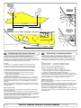
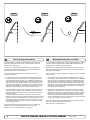
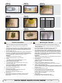
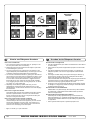
Positioning of the tunnel / thruster
The
bebe
asas
farfar
forward
as possible
(Fig.(Fig.
1) 1)
The Thruster
Thrustershould
should
forward
as possible
Because
around
thethe
boats
pivot
point,
it is it
very
Becauseofofthe
theleverage
leverageeffect
effect
around
boats
pivot
point,
is very
important
actual
effect
in the
boatboat
to get
as itfar
importantfor
forthe
thethrusters
thrusters
actual
effect
in the
to itget
asfor-ward
far foras
possible.
The relative
distancedistance
change from
the from
boatsthe
pivot
pointpivot
to the
ward
as possible.
The relative
change
boats
thruster
the change
of the
actual
thrustof
foractual
the boat.
point to will
thebe
thruster
will be
change
thrust for the boat.
Example:
Example:
A:
= 605kgm
torque
to rotate
the boat
A: 55kg
55kgthrust
thrustxx11m
11mleverage
leverage
= 605kgm
torque
to rotate
the boat
B:
= 550kgm
torque
to rotate
the boat
B: 55kg
55kgthrust
thrustxx10m
10mleverage
leverage
= 550kgm
torque
to rotate
the boat
In
more
thrust
to turn
the the
boatboat
around.
In position
positionAAyou
youwill
willget
get10%
10%
more
thrust
to turn
around.
The
bebe
placed
as as
deep
as possible
(Fig. (Fig.
2)
The thruster
thrustershould
should
placed
deep
as possible
2)
The
asas
deep
as as
possible
for two
reasons:
The tunnel
tunnelshould
shouldbebeplaced
placed
deep
possible
for two
reasons:
1.
down
air air
from
the the
surface
which
will will
1. So
So that
thatititdoes
doesnot
notsuck
suck
down
from
surface
which
destroy
destroythe
thethrust
thrustcompletely.
completely.
2.
a water
pressure
to get
maximum
2. To
To get
getas
ashigh
highasaspossible
possible
a water
pressure
to get
maximum
efficiency
efficiencyfrom
fromthe
thepropeller.
propeller.
Generally
tunnel
should
be be
a minimum
of ½of
x the
Generallythe
thetop
topofofthe
the
tunnel
should
a minimum
½ xtunnel
the
diameter
below the
waterline.
This is anThis
absolute
we rectunnel diameter
below
the waterline.
is anminimum
absoluteand
minimum
ommend
that it is at least
diameter
() below
the waterline.
and we recommend
that¾itxistunnel
at least
¾ x tunnel
diameter
(☺) below
A
really
good distance
aboutdistance
1/1 x tunnel
diameter
below
the
the
waterline.
A reallyisgood
is about
1/1 x()
tunnel
diameter
waterline.
(☺☺) below the waterline.
When
the
tunnel
30-35
cm*/1
feetfeet
below
the surface,
Whenyou
youget
getthe
thetop
topofof
the
tunnel
30-35
cm*/1
below
the
other
factors
should
be should
considered
more important,
moving the
surface,
other
factors
be considered
morei.e.
important,
i.e.thruster
furtherthe
forward.
moving
thruster further forward.
Optimal
Optimaltunnel
tunnellength
length
If the
the
friction
inside
willwill
reduce
the water
speed
the tunnel
tunnelgets
getstotolong,
long,
the
friction
inside
reduce
the water
and
thereby
the thrust.
speed
and thereby
the thrust.
If the
(normally
only
in the
bottom
section
of theoftunthe tunnel
tunnelgets
getstotoshort
short
(normally
only
in the
bottom
section
the
nel)
you you
can can
get cavitation
problems
as theas
water
notwill
have
time to
tunnel)
get cavitation
problems
the will
water
nothad
have
“straighten”
before reaching
the propeller
This (Fig.
cavitation
had time toitself
“straighten”
itself before
reaching(Fig.
the3&4).
propeller
3&4).
will
performance
as well
as creatingas
a lot
of as
noise.
Thisreduce
cavitation
will reduce
performance
well
creating a lot of
The
optimal tunnel length is 2 to 4 x tunnel diameter and you should avoid
noise.
tunnels
longertunnel
than 6length
to 7 times
diameter
as the
performance
The optimal
is 2 the
to 4tunnel
x tunnel
diameter
and
you should
reduction
is then
clearly
noticeable.
avoid tunnels
longer
than
6 to 7 times the tunnel diameter as the
performance reduction is then clearly noticeable.
10
6
N
D
Positionierung
Tunnel
/ Thruster
Plassering avvon
tunnel
og thruster
Tunnelen
bør plasseres
lengst
mulig
frem
i baugen
(Fig.
Tunnelplazierung
soweit
vorne
wie
möglich
(Fig.
1) 1)
For
oppnå
mest mulig
moment
rundt vom
båtens
dreiepunkt,
det meget
Um åeinen
möglichst
großen
Abstand
Drehpunkt
deserSchiffes
zu
viktig
å plassere
tunnelen
så langt
fremmeweit
somvorne
mulig.einzubauen.
Avstanden fra
erreichen,
ist der
Sidepower
möglichst
båtens
dreiepunkt til thruster
vil ha stor vom
betydning
på thrusterens
effekt.
Eine Vergrößerung
des Abstandes
Drehpunkt
des Schiffes
hat eine direkte Auswirkung auf die verfügbare Schubkraft.
Eks.:
A:
55kg skyvekraft
x 11m moment = 605kgm skyvekraft
Beispiel
:
B:
x x 10m
= 550kgm
skyvekraftdes Bootes
A: 55kg
55kgskyvekraft
Schubkraft
11mmoment
= 605kgm
zum Wenden
Posisjon
vil gi 10% mer
skyvekraft
til rotasjon.
B: 55kg A
Schubkraft
x 10m
= 550kgm
zum Wenden des Bootes
In Beispiel A stehen damit 10% mehr Schubkraft zur Verfügung.
Tunnelen skal plasseres dypest mulig (Fig. 2)
Tunnelen
skal so
plasseres
såmöglich
dypt sompositionieren
mulig av to grunner:
Den Tunnel
tief wie
(Fig. 2)
1.
SåTunnel
luft ikkeaus
suges
ned
i tunnelen
ødelegger
skyvekraften.
Den
zwei
Gründen
soå tief
wie möglich
positionieren:
2.
Ved å øke
vanntrykket
jobber propellen
merdie
effektivt.
1. Damit
nicht
Luft mitangesaugt
wird, die
Schubkraft
Hovedregelen
at tunnelen skal plasseres minimum ½ x tunnelen dia.
vollständigerherabsetzt.
under
Anbefalt dybde
minst ¾ x dia.zu
under
vannlinje
2. Umvannlinje.
einen möglichst
hohenerWasserdruck
erhalten,
um().
die Når
tunnelen
er plassert
33-35
cmPropellers
under vannlinjen
bør andre faktorer vurmaximale
Effizienz
des
erreichen.
deres
som viktigere,
å plassere
tunnelen
lengre
frem.TunnelDie Oberkante
desd.v.s.
Tunnels
muß mind.
einen
halben
durchmesser unterhalb der Wasserlinie liegen. Dieser Wert ist ein
Optimal
tunnel
lengdeBesser ist ein Wert von ca. ¾ des
absolutes
Minimum.
Dersom
tunellen blir for(☺).
lang Optimal
vil friksjonen
i tunellen
reduser
Tunneldurchmessers
ist eine
Abstand
vonvannhastig1/1 x
heten
og derved effekten.
Tunneldurchmesser
(☺☺) zur Wasserlinie.
Dersom
blir fordes
kortTunnels
(normalt30-35cm*
bare i nedre
del avunterhalb
tunellen) kan
Liegt dietunellen
Oberkante
/ 1fuß
der det
oppstå
kavitasjons
problemer
vannet ikke
har tid / av-stand
til å «rette
Wasserlinie,
können
anderedaFaktoren
berücksichtigt
werden.
opp strømningsretningen» før det treffer propellen (Fig. 3&4). Denne
kavitasjonen
vil redusere effekten og lage mye støy.
Optimale Tunnellänge
Den
optimale
lengden
er 2reduziert
til 4 ganger
tunell
diameteren og die
dersom
Bei einem
zutunell
langem
Tunnel
der
Reibungsverlust
tunellen
blir så mye som 6 und
til 7 ganger
diameteren
i lengde vil effekt tapet
Wassergeschwindigkeit
damit die
Schubkraft.
bli
merkbart.
Beiklart
einem
zu kurzem Tunnel (häufig im unteren Bereich des
Tunnels) können Kavitationsprobleme entstehen, da sich das
Wasser nicht gerade auszurichten kann (Fig. 3&4). Diese Kavitation ist leistungsreduzierend und kann starken Lärm verursachen.
Die optim. Tunnellänge ist das 2-4 fache des Tunneldurchmessers.
Tunnellängen von mehr als dem 6-7 fachen des Tunneldurchmessers sollten vermieden werden, da dadurch die Leistung
reduziert wird.
SP 75 Ti / SP 95 Ti / SP 125 Ti 2.5.1- 2007
EB 20/110 S - EB 40/160 S - EB 60/160 S - EB 75/185 S - EB 90/185 S
1.0.6 - 2014
Fig. 2
Fig. 1
R = 0,1 x D (10%)
D
R = 0,1 x D (10%)
�
☺
Fig. 4
Fig. 3
GB
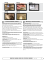
Tunnel ends
N
D
Formgebung
der Tunnelenden
Tunnelåpninger
Rounded tunnel
ends
will maximize
thrust and
minimize
Rounded
tunnel
ends
will maximize
thrust
and noise.
minimize
noise.
Avrundede åpninger
vil minke støy,
og maksimere
effekt.
Abgerundete
Tunnelenden
erhöhen
die Schubkraft
und
reduzieren das Geräuschniveau.
much
as possible.rounding the tunnel connection to the hull-side as
We
recommend
The optimum
rounding has a radius of 10% of the tunnels diameter.
much
as possible.
The optimum rounding has a radius of 10% of the tunnels diameter.
Den Bereich
optimale Tunnelende
avrundingen har
en radie som
er Rumpfes
10% av tunnelens
diamDer
/ Außenseite
des
ist soweit
eter.
möglich
abzurunden. Der optimale Wert für den Radius dieser
Rundung beträgt 10% des Tunneldurchmessers.
Important advantages over sharp tunnel to hull connections are:
Vorteile gegenüber einer scharfen Tunnel / Rumpfverbindung sind:
The
cavitation
that tunnel
will come
sharp tunnel
endofwhen
water
1.
rounded
endfrom
will aprevent
creation
turbulence
cavitation
passes by fast,
thereby
preventing
a double
negative
impact
on
that will
come
from a sharp
tunnel
end when
water
passes
the thrustbyand
noise
level preventing
(Fig. 1 & 2).a double negative impact on
fast,
thereby
the
- The
turbulence
/ cavitation
blocks
thrust
and noise
level (Fig.
1 &the
2).outer area of the tunnel
- The
and thereby
reduces
the effective
tunnel
diameter
and
turbulence
/ cavitation
blocks
the outer
area
of thrust.
the tunnel
- and
The turbulence
/ cavitation
hits the propeller
and thereby
thereby reduces
the effective
tunnel diameter
andreduce
thrust.
- The
the propellers
performance
noise. and thereby reduce
turbulence
/ cavitationand
hitscreates
the propeller
the propellers performance and creates noise.
tasjon, noe somTunnelenden
vil oppstå vedverhindern
en installasjon
med skarpe/ kanter.
1. Abgerundete
Turbulenzen
Kavitation,
Turbulensen
forårsaker mer støy,
og begrenserauftreten.
skyvekraften.
wie
sie an scharfenkantigen
Tunnelenden
Damit
werden
- Turbulensen
kavitasjonen
blokkerer tunnelen
og svekker
skyvekrafzwei /negative
Auswirkungen
auf Schubkraft
und
ten.
Geräuschentwicklung
vermieden (Fig. 1 & 2).
- ITurbulenz
det kavitasjon
og turbulens
når propellen
påvirkes ytelsen
til denne
/ Kavitation
blockieren
den äußeren
Tunnelbereich.
og øker støyen.
Dadurch
werden effektiver Tunneldurchmesser und Schubkraft reduziert.
2. -En
avrundet
tunnelåpning
gjør trifft
ogsåauf
at thrusteren
sugerund
vannreduziert
langs
Die
Turbulenz
/ Kavitation
den Propeller
skroget
påEffektivität
båten. Dermed
et lavtrykk
som vil hjelpe å suge
dessen
und oppstår
führt zudet
zusätzl.
Geräuschentwicklung.
We recommend rounding the tunnel connection to the hull-side as
Important advantages over sharp tunnel to hull connections are:
1. The rounded tunnel end will prevent creation of turbulence
2. The curved tunnel end makes the thruster take water also from
The
alongcurved
the hull-side,
a vacuum
that willtake
suckwater
the boat
2.
tunnel creating
end makes
the thruster
also from
along
sideways
therebycreating
give additional
thrust
(Fig.
& 4). the boat
theand
hull-side,
a vacuum
that
will3suck
sideways
With a sharp
tunnel
end,give
the thruster
will thrust
be unable
and
thereby
additional
(Fig.to3take
& 4).water
With
from along
thetunnel
hull-side,
and
you
will notwill
getbe
theunable
desiredtovacuum
a sharp
end,
the
thruster
take water
from
and additional
This and
“free”you
additional
can
in optimal
along thethrust.
hull-side,
will notthrust
get the
desired
vacuum
and
installations
be as
muchThis
as 30
- 40%
of the total
thrust.
additional
thrust.
“free”
additional
thrust
can in optimal
installations be as much as 30 - 40% of the total thrust.
NB! A Sidepower thruster propeller does not cavitate at working
A
speed
so that all
cavitation
and cavitation
in the
will
NB!
Sidepower
thruster
propeller
does notnoise
cavitate
at tunnel
working
speed
be caused
by the
installation.
so that
all tunnel
cavitation
and cavitation noise in the tunnel will
NB! be
Even
if it is not
possible
to installation.
make the perfect rounding, it is very
caused
by the
tunnel
Even
important
to not
round
the tunnel
end asthe
much
as possible.
A it is very
NB!
if it is
possible
to make
perfect
rounding,
important
angled tunnel
to hull the
connection
will also
do much
of the same
to round
tunnel end
as much
as possible.
A
angled
job as a tunnel
rounded
(see page
10, Fig.
1b & 1d).
toconnection
hull connection
will also
do much
of the same
job as a rounded connection (see page 20, Fig. 1b & 1d).
12
Vi anbefaler å avrunde tunnelåpningene mest mulig.
Hvorfor er en avrundet tunnelåpning så viktig?
1. En avrundet tunnelåpning vil forhindre at det oppstår turbulens / kavi-
båten i dreieretningen. Med skarpe åpninger klarer ikke thrusteren å
suge vann langsermöglichen,
skroget, og lavtrykket
uteblir.entlang
Så myeder
somRumpf40% av
2. Abrundungen
daß Wasser
skyvekraften angesaugt
har blitt måltwerden
til å liggekann.
her på
noen installasjoner.
außenseite
Dadurch
entsteht ein
Vakuum ("zusätzliche" Schubkraft"), das das Schiff seitwärts
NB!
Propellene
Sidepower
thrustere kaviterer
ikke på
arbeids-hasbewegt
(Fig. til
3&
4). Bei scharfkantigen
Enden
kann
kein
tighet, entlang
så kavitasjon
og støy som oppstårangesaugt
som følge av
kavitasjon,
Wasser
der Rumpfaußenseite
werden,
skapes das
av tunnel
installasjonen.
wodurch
benötigte
Vakuum nicht zustande kommt.
NB!
SelvSchubkraft
der en perfekt
avrunding
ikke er mulig
er det viktig
av
Diese
kann
bei optimaler
Installation
bis zuå runde
30-40%
så mye
som mulig,
en tunnelåpning med skråkant vil ha
derkantene
absoluten
Schubkraft
betragen.
NB !
NB !
stor effekt fremfor en med skarpkant (se side 10, ill. 1b & 1d).
Sidepower Propeller sind so ausgelegt, daß sie nicht
kavitieren, sodaß die Geräuschentwicklung aufgrund von
Kavitation durch die Tunnelinstallation bedingt ist.
Ist eine optimale Abrundung nicht möglich, so sind die
Tunnelenden soweit möglich abzurunden. Angeschrägte
Tunnel / Rumpfverbindungen sind zu einem gewissen Grad
ebenfalls mit ähnlich positiven Auswirkungen wie eine
Abrundung verbunden (siehe Seite 20, Fig. 1b & 1d).
SP 75 Ti / SP 95 Ti / SP 125 Ti 2.5.1- 2007
EB 20/110 S - EB 40/160 S - EB 60/160 S - EB 75/185 S - EB 90/185 S
1.0.6 - 2014
7
Fig. 1
Fig. 2
�
GB
Fig. 3
☺
☺
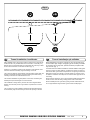
Prevent drag from tunnel
D
N
Optimaler
Strömungsverlauf
am Rumpf
Motstand
forårsaket av tunnel
A
in in
sailboats
or fast
powerboats
is that
A possible
possibleproblem
problem
sailboats
or fast
powerboats
is they
that get
theya get a
drag
ofof
thethe
tunnel,
as as
thisthis
becomes
a “flat”
area area
drag from
fromthe
theback
backface
face
tunnel,
becomes
a “flat”
facing
facingthe
thewater
waterflow
flow(Fig.
(Fig.1).1).
Et
mulig problem
seilbåter
ellerBooten
meget hurtiggående
båter er motstand
Segelboote
undfor
sehr
schnelle
können gelegentlich
durch
iauf
tunnelen.
Aktre endeFläche
på tunnelen
vil være auftreffendes
en liten loddrettWasser
flate mot
die rückseitige
des Tunnels
vannstrømmen
som(Fig.
skaper
gebremst werden
1).uønsket motstand.
This
with
thethe
thruster
spinning
(passive)
This can
canalso
alsocreate
createproblems
problems
with
thruster
spinning
(passive)
and
or or
driving
thethe
boat
withwith
water
being
and making
makingnoise
noisewhile
whilesailing
sailing
driving
boat
water
being
pushed
atat
high
speed.
pushedthrough
throughthe
thetunnel
tunnel
high
speed.
Denne
flatendazu
kan også
forårsake
problemer
med atdurch
vann føres
inn i tunDies kann
führen,
daß sich
der Thruster
den permanelen
under
seilas, eller kjøring
i høypassiv
fart ogzu
fårdrehen
da propellen
til å rotere,
nenten
Wasserdurchfluß
hörbar
beginnt.
dette skaper uønsket støy.
This
ways,
depending
on what
is is
This can
canbe
besolved
solvedinintwo
twodifferent
different
ways,
depending
on what
possible
possibleororeasier
easiertotodo.
do.
Det
er to mulige løsninger på problemet, avhengig av hva som er enklest
werden.
å få til på båten.
1.
normally
reduces
the drag
mostmost
is to make
1. The
Thebest
bestsolution
solutionwhich
which
normally
reduces
the drag
is to
a
recess
in the hull
at the
back
of the
tunnel.
Thereby
back face
make
a recess
in the
hull
at the
back
of the
tunnel.the
Thereby
the
is
gone
andisabout
theabout
drag (Fig.
2).drag
The depth
andThe
shape
of this
back
face
goneall
and
all the
(Fig. 2).
depth
and
recess
depend
on the
Basically
should
not seeyou
the back
shape will
of this
recess
will boat.
depend
on theyou
boat.
Basically
face
of the
when
standing
in front
of the
tunnel at
the
should
nottunnel
see the
back
face ofdirectly
the tunnel
when
standing
directly
angle
ofof
the
boats
centreline.
The angle
or down
backwards
in front
the
tunnel
at the angle
of theupboats
centreline.
Theof the
insert
depends
on theofhull
butthe
normally
it is angled
angleinupthe
or hull,
down
backwards
theshape,
insert in
hull, depends
on
slightly
because
of the water
flow on slightly
this areadown
of thebecause
hull.
the hulldown
shape,
but normally
it is angled
of
1. im
DenRumpfbereich
løsningen somhinter
vanligvis
reduserer
mest ervornimmt.
å lage
dem
Tunnel motstanden
eine Aussparung
en fordypning
i skroget
i aktre ende
av störender
tunnelåpningen.
loddrette
Dadurch
werden
Auftreffläche
und
EffektDen
eliminiert
flaten2).
vil da forsvinne og dermed motstanden. Hovedregelen å følge
(Fig.
er at bakkanten
tunnelen
ikke skal synes
når vom
man står
Tiefe
und Formavdieser
Aussparung
hängen
Bootrett
ab.foran
båten
og ser akterover
langs båten
utformingen
Die
Innenseite
des Tunnels
solltesenterlinje.
von vorneDybden,
prinzipiell
nicht
og vinkling
av fordypningen avhenger av båttypen, og hvordan vannet
sichtbar
sein.
følgermögliche
skroget, men
de fleste
båter vil være
tjent med
fordypning
Der
Winkel
der Aussparung
hängt
meistenvon
der
som vinkler lett
2). die Wasserströmung in diesem
Rumpfform
ab.nedover
Bedingt(Fig.
durch
2. The drag will also be reduced a lot, especially in fast power boats, by
a deflector
spoiler
in front
of the
tunnel. This
will power
push the
2. making
The drag
will also/ be
reduced
a lot,
especially
in fast
water
out from athe
hull so that
most in
of front
it passes
by tunnel.
the backThis
face
boats,flow
by making
deflector
/ spoiler
of the
of
tunnel
3).flow out from the hull so that most of it passes
willthe
push
the(Fig.
water
The
shape
and
size
this
deflector
by the
back
face
ofofthe
tunnel
(Fig.will
3).depend on the hull shape.
Basically
youand
should
back face
the tunnel
when
The shape
sizenot
of see
this the
deflector
will of
depend
on the
hullstanding
directly
front of the
at the
of the
boats
The
shape. in
Basically
youtunnel
should
not angle
see the
back
facecentreline.
of the tunnel
easiest
way of making
this
to let
parttunnel
of theat
tunnel
stick out
in the
when standing
directly
in is
front
ofathe
the angle
of the
lower
areaThe
of the
hole, and
as a this
support
a of
boatsforward
centreline.
easiest
wayuse
of this
making
is totoletmould
a part
soft
curve/spoiler
shape.
the tunnel
stick out
in the lower forward area of the hole, and use
2. Motstanden vil også reduseres av en spoiler i forkant av tunnelen.
Spoileren
fører det meste av vannstrømmen
rundt
forbi tunnelen.
2. Der
Geschwindigkeitsverlust
kann speziell
bei og
schnellen
Booten
Størrelsen
og Abweiser
utformingen
på spoileren
avhenger
av båten.
Hovedredurch
einen
bzw.
Spoiler vor
dem Tunnel
deutlich
gelen er atwerden.
bakkanten av tunnelen ikke skal synes når man står rett
reduziert
foranWasser
båten ogwird
ser akterover
langs båten
senterlinje.
Denan
enkleste
Das
so beeinflußt,
daß es
größtenteils
der
måten å lage
spoileren
pågeleitet
er å la tunnelen
stikke
frontalen
Fläche
vorbei
wird (Fig.
3). ut i forkant av tunnelen, og und
forme
spoileren
mot den hängen
(Fig. 3). von der Rumpfform ab.
Form
Größe
desopp
Abweisers
the water flow on this area of the hull.
this as a support to mould a soft curve/spoiler shape.
Remember to still round the tunnel ends as much as possible to get
optimum
thruster
performance
minimum
noise.
Foras
more
Remember
to still
round the and
tunnel
ends as
much
possible to get
information
on howperformance
to practically do
this
see pagenoise.
10. For more
optimum thruster
and
minimum
information on how to practically do this see page 20.
14
8
Das Problem kann je nach Möglichkeit auf zwei Arten beseitigt
1. Der störende Effekt wird am deutlichsten reduziert, indem man
Bereich sollte dieser Winkel leicht nach unten gerichtet sein.
Prinzipiell sollte auch hier die Innenseite des Tunnels von vorne
Detnicht
er alltid
viktig åsondern
avrunde durch
tunnelåpningene
mestverdeckt
mulig for sein.
å motvirke
sichtbar,
den Abweiser
støyDieser
og for läßt
å få mest
mulig effekt
av thrusteren.
sich einfach
realisieren,
indem man den Tunnel ein
MerStück
informasjon
om Rumpf
dette påherausstehen
side 10.
aus dem
läßt und darauf einen
geschwungenen Abweiser / Spoiler formt.
Die Tunnelenden sind zur vollen Leistung und minimalen
Geräuschentwicklung des Thrusters weitgehend abzurunden.
Weitere Informationen siehe Seite 20.
SP 75 Ti / SP 95 Ti / SP 125 Ti 2.5.1- 2007
EB 20/110 S - EB 40/160 S - EB 60/160 S - EB 75/185 S - EB 90/185 S
1.0.6 - 2014
Fig. 1
☺
Pos. A
Pos. B
�
☺
Min
�
GB
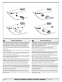
Tunnel installation in sailboats
N
D
Installation
in Segelbooten
Tunnel
installasjon
på seilbåter
Many
racing
type
hullhull
which
means
that that
it is very
flat botManysailboats
sailboatshave
havea a
racing
type
which
means
it is very
tomed
and hasand
a very
in thedraft
bowinsection.
It issection.
therebyItvery
flat bottomed
hasshallow
a verydraft
shallow
the bow
is
difficult
to say
impossible
to fitimpossible
a tunnel thruster
usualthruster
way, at least
therebynot
very
difficult
not to say
to fit athe
tunnel
the
as
far forward
the as
hullfar
as forward
a thruster
(Fig.
1).
usual
way, at in
least
inshould
the hullbeas
a thruster
should be
Mange
seilbåtskrog
byggeteinen
for å oppnå
fart. De har auf,
brede
skrog
Segelboote
weisenerhäufig
Rumpfhøy
in Rennform
was
som
stikker
dypt Rumpf
i baugen.
gjør
det vanskelig
installere
einenikke
sehr
flachen
imSkrogtypen
Bugbereich
bedeutet.
Es istå daher
en
thrustertunnel
på vanlig
måte, spesielt
med tanke
pågewünschten
å plassere den
schwierig
oder fast
unmöglich,
den Tunnel
an der
langt
nok frem Stelle,
(Fig. 1).also möglichst weit vorne im Bug zu plazieren
(effektivsten)
However, it is possible to install a tunnel thruster in most sailboats, even
when
the hull
not directly
support
the fitting
of a in
tunnel.
However,
it isdoes
possible
to install
a tunnel
thruster
most sailboats,
Thrustertunneler kan allikevel installeres i de fleste seilbåter. Dette gjøres
ved
å la en ist
deles
av vielfach
tunnelenmöglich
stikke ut unter
i underkant
avBedingungen
skroget. Tunnelen
Trotzdem
diesen
eineer
sterk
nok til dette,
og thrusteren
blir wenn
plassert
lavTunnel
nok og damit
langt nok
fremme.
Bugschraube
einzubauen,
auch
der
nicht
völlig
This is done by fitting the tunnel halfway into and halfway under-neath the
existing
hull and
then strengthen
and smoothening
the waterunderflow by
This is done
by fitting
the tunnelit halfway
into and halfway
moulding
bulb around
/ underneath
the tunnel.
neath theaexisting
hull and
then strengthen
it and smoothening the
Dette gjøres ved at øvre halvdel av tunnelen støpes inn i skroget, tunnelen
ved å støpe
kul rundt tunnelen
og integriert,
jevne den ut
Derstyrkes
Tunneli underkant
wird zur Hälfte
in denenbestehenden
Rumpf
mest
mulig. Hälfte geht über diesen hinaus. Der Tunnel muß nur
die andere
This will allow installation in good position on the boat, maintaining the
reliability
and space
advantages
of aposition
tunnel thruster.
This will allow
installation
in good
on the boat, maintaining
Denne metoden brukes av noen av de helt største seilbåt-produsentene i
verden,
de viser
til at
den ikke girinutslag
på fart Position
under normal
seilas.
Dies erlaubt
eine
Installation
geeigneter
bei Nutzung
(Fig. 1).
even when the hull does not directly support the fitting of a tunnel.
water flow by moulding a bulb around / underneath the tunnel.
the reliability and space advantages of a tunnel thruster.
This installation is being used by some of the world’s largest sailboat
builders,
and has is
been
proven
give
little of
to the
no speed
loss
for normal
This installation
being
usedtoby
some
world’s
largest
sailboat
cruising.
builders, and has been proven to give little to no speed loss for
normal cruising.
This can also be a good installation method for flat bottomed barges to
avoid
extremely
tunnels
and hugemethod
oval tunnel
openings
in thebarges
hull.
This can
also belong
a good
installation
for flat
bottomed
to avoid extremely long tunnels and huge oval tunnel openings in the
hull.
16
(Fig. 1).
vom ursprünglichen Rumpf umgeben ist.
noch verstärkt und strömungsgünstig abgerundet werden.
der Zuverlässigkeits- und Platzvorteile einer Tunnelschraube.
Denne installasjonen kan også være gunstig for båter med flate bunner,
for
å unngå
ekstremt lange
og store
tunnelåpninger.
Diese
Installationsart
wirdtunneler
von einigen
derovale
weltweit
führenden
Segelboothersteller verwendet und führt meistens nur zu einem
äußerst geringen bzw. gar keinem Geschwindigkeitsverlust.
Diese Bauweise ist auch für Barkassen (z.B. Flußboote) mit
flachem Bug geeignet, um einen zu langen Tunnel und große
ovale Tunnelöffnungen im Rumpf zu vermeiden.
SP 75 Ti / SP 95 Ti / SP 125 Ti 2.5.1- 2007
EB 20/110 S - EB 40/160 S - EB 60/160 S - EB 75/185 S - EB 90/185 S
1.0.6 - 2014
9
Fig. 1
R
D
Fig. 2
Fig. 3
GB
Tunnel installation
Fig. 4
N
Tunnel installering
We recommend that a professional does the fibreglass fitting of the
tunnel. These instructions are only general, and do not explain in
any way the details of fibreglass work. Problems caused by faulty
installation of the tunnel, are the installers full responsibility.
Sleipner Motor anbefaler at innstøping av glassfibertunnelen utføres
av kyndig personell. Denne instruksjons manualen gir ikke detaljerte
opplysninger om glassfiberstøpning. Problemer som skyldes installering er installatørens fulle ansvar.
Find the position in the boat considering the information given earlier in
this manual and the applicable measurements for the thruster model you
are installing.
Bestem plassering av tunnelen ut i fra informasjonen gitt tidligere i manualen, og de angitte mål for thrusteren du skal installere.
Mark the centre of the tunnel on both sides. Drill a 6mm hole horizontally
in these marks (Fig. 1).
Bend a ø 5mm steel bar as shown with the “tip” bent back at the tunnel
radius and mark the circle for the tunnel opening (outside diameter of the
tunnel). Cut the hole with a jigsaw (Fig. 2).
Grind off the gelcoat and polyester so that you are down in the “real fibreglass” in an area of 12cm around the hole both inside and outside in the
hull to cast the tunnel to the hull (Fig. 3).
Insert the tunnel and mark its shape to fit the hull (Fig. 4). (if you are installing with a deflector/spoiler, leave a part or the tunnel of the front- and
underside of the tunnel to have a base for this (see page 20, Fig. 2). Cut
the tunnel ends to the desired shape and lightly sand its surface and
clean with acetone or similar where you are going to apply fibreglass.
NB! Do not cast/glass on the area were the thruster will be placed.
Merk av senter på tunnelen på babord og styrbord side. Bor et 6 m.m.
vannrett hull, på begge sider (Fig. 1).
Bøy til og tilpass en 5 m.m. stålstang, som vist på fig. 2 der den tilbakebøyde enden skal markere tunnelens radius. Stikk enden inn å marker
tunnelens ytre diameter, skjær ut hullet med en stikksag (Fig. 2).
Puss av gelcoat og polyester så glassfiberen ligger bar i et 12 cm stort
område rundt tunnel hullet. Dette må gjøres på innsiden og utsiden av
skroget, før tunnelen støpes fast i skroget (Fig. 3).
Sett inn tunnelen og marker hvor det skal kappes for å passe i skroget
(Fig. 4). Hvis det skal støpes en spoiler i forkant av tunnelen bør en del av
tunnelen stikke ut i for og underkant av skroget for å støpe spoileren mot
(Side 20, Fig. 2). Kapp tunnelen i ønsket størrelse. Slip lett med slipepapir, og vask med aceton der hvor det skal støpes med glassfiber.
NB ! Det må ikke støpes der hvor thrusteren skal monteres.
Then cast the tunnel to the inside of the hull, use at least 8 layers of 300 g
glass and resin, preferably alternating mat and rowing types of fibreglass
(see page 20, Fig. 1). If you are rounding the tunnel ends to the perfect
10% radius you may in some cases have to make further layers inside to
preserve the desired hull thickness.
Støp fast tunnelen først på innsiden av skroget, bruk minst 8 lag med 300
g Glassfibermatte, og polyester. Ved bruk av alternative materialer, glassfiber matter eller rovingtyper (Se s. 20, Fig. 1). Hvis tunnelåpningene
avrundes til den optimale 10% radius må ofte legge ekstra lag med polyester glassfibermatte på innersiden av tunnelen, for å oppnå riktig tykkelse i
forhold til skrogtykkelsen.
NB! Make sure that any gap between the tunnel and the hull are completely filled with resin/fibreglass. In areas where you can not access to
make normal layers of resin/fibreglass, a resin/ fibreglass mixture must be
filled in that area.
NB ! Forsikre deg om at overgangene mellom tunel og skrog er nøye
sammenstøpt. På steder en ikke kommer til med vanlige lag med polyester/glassfiber matte, sørg for og lage en blanding av polyester og glassfiber, som fylles i dette.
10
EB 20/110 S - EB 40/160 S - EB 60/160 S - EB 75/185 S - EB 90/185 S
1.0.6 - 2014
Fig. 1a
Fig. 1c
 
Fig. 1
Fig. 1b
Fig. 1d
Fig. 2
D
x
D
Tunnel installation
GB
Soften the
of of
10%
of the
tunnel
diameter
(Fig.(Fig.
1a) or
Soften
theedges
edgeswith
witha aradius
radius
10%
of the
tunnel
diameter
make
slope awith
a length
10-15%
the tunnel
diameter
1c). If
1a)
oramake
slope
with aoflength
of of
10-15%
of the
tunnel(Fig.
diameter
this is1c).
not possible,
at least
round at
theleast
tunnel
end as
as end
possible.
(Fig.
If this is not
possible,
round
themuch
tunnel
as
much
as possible.
We advice
to also cast two layers on the outside of the tunnel/hull for an
6-8cm area (Fig. 1c & 1d).
We advice to also cast two layers on the outside of the tunnel/hull for
Youarea
must6-8cm
apply topcoat/epoxy
an
(Fig. 1c & 1d).on the areas outside where you have
grounded or moulded to again make these waterproof.
You
apply topcoat/epoxy
on theare
areas
where
you have
NB! must
All original
Sidepower tunnels
fullyoutside
waterproof
when
grounded
or moulded
to again make these waterproof.
they are
delivered.
This means
that unless
you want,tunnels
becauseare
of special
reasons, to have
anNB!
All original
Sidepower
fully waterproof
when
other they
colourare
on it,
you do not have to apply topcoat or the several layers
delivered.
of primer that is necessary on the boats’ hull to make it water-resistant.
This
that unless
youone
want,
because
oftospecial
reasons,
to
Sandmeans
it very lightly
and apply
layer
of primer
make the
antifouling
have
sit. another colour on it, you do not have to apply topcoat or the
several layers of primer that is necessary on the boats’ hull to make
original
Sidepower tube itself is fully water-resistant without treatment
itThe
water
resistant.
except in the areas where you have bonded it to the hull.
Sand
it very lightly and
one layer
of areas
primerwhere
to make
Apply topcoat/epoxy
paintapply
and primer
on the
you the
have
antifouling
grounded orsit.
moulded as these areas give the water access to the hull
which normally is not waterproof without these applications outside.
The original Sidepower tube itself is fully water resistant without
PS! Avoid all casting where the motor-bracket is to be placed,
treatment
except in the areas where you have bonded it to the hull.
as this will cause misfit and possible failure of the
gearhouse.
Apply
topcoat/epoxy paint and primer on the areas where you have
grounded or moulded as these areas give the water access to the
hull which normally is not waterproof without these applications
outside.
N
D
Fig. 3
0,
1-
x
0,
1
R = D x 0,1
5
D
R = D x 0,1
,15
-0
0,1
Tunnelinstallation
Tunnel
installering
Rund av tunnelendene
radius
10% av
tunneldiameter
(Fig. 1a),
Runden
Sie die Kantenmed
miten
einem
Radius
(10%
des Tunneldurcheller lag enab
skråkant
10-15%
av tunneldiameter
1c). Der
messers)
(Fig. 1a)
oder machen
Sie eine (Fig.
Schräge
mit dette
einer ikke er
mulig skal
kantene
rundes av mest mulig.(Fig. 1c). Ist beides
Länge
vontunnel
10-15%
des Tunneldurchmessers
nicht
möglich,
sind die
Tunnelenden
soweit möglich
Vi anbefaler
å støpe
to lag
utenpå tunnellavrundingen
ogabzurunden.
over et område
på 6-8cm
(Fig. 1c & 1d).
Auf
der Außenseite
zusätzlich zwei Schichten im Bereich Rumpf /
Tunnel
auf
einer
Fläche
von 6-8cm
auftragender
(Fig.
1d).
Gelcoat eller lignende må påføres
på områdene
det 1c
har&blitt
pusset
eller støptauf
forden
å gjøre
glassfiberen
vanntett. oder laminierten Flächen
Danach
äußeren,
angeschliffenen
Gelcoat/Topcoat/Epoxy
zur
wasserdichten
Versiegelung
aufbringen.
NB ! Alle originale Sidepower tunneler er vanntette
ved levering!
NB
! Original
Sidepower
tunnelfarge
sinderindet
ausgeliefertem
Så fremt
man ikke
ønsker en annen
ikke nødvendig å påføre
Zustand
wasserdicht.
Gelkoat,
Topkoatabsolut
og flere lag
med primer for å gjøre tunnelen vanntett.
Wird
nicht eine
spezielle
Farbeog
gewünscht,
sind for
keinerlei
Puss tunnelen
med
fint slipepapir
påfør et lagso
primer
å få bunnstoff
Gelcoat,
til å sitte. Topcoat oder Primer nötig, die ansonsten zur
Wasserdichtigkeit benötigt werden.
Sidepowertunnelen er helt vanntett uten behandling med unntak av de
Empfehlenswert
iststøpt
ein leichtes
anschleifen und aufbringen einer
områder det som er
fast i skroget.
Primerschicht zur besseren Haftung des Antifouling.
Påfør Gelcoat/Topcoat/epoxy og primer på de områder som er pusset ned
Original
Sidepowertunnel
auch
ohnemed
Behandlung
absolut
eller støpt.
Vann skal ikke hasind
direkte
kontakt
glassfiberen
i skroget
wasserdicht.
fordi dette normalt ikke er vanntett.
Auf
oder
angeschliffenen
Flächen
ist Gelcoat
/ Topcoat
/
PS !laminierten
Det må ikke
støpes
der braketten
til thrusteren
skal
stå.
EpoxyPassformen
und Primerer
aufzubringen,
da diese
Bereiche
ohne
nøyaktig tilpasset,
og en
feilplassert
brakett
entsprechende
Behandlung
nicht wasserdicht sind.
kan forårsake
svikt i girhus.
PS ! Im Bereich der Motorhalterung darf nicht laminiert werden, da dies zu Ungenauigkeiten bei der Montage und
damit einem möglichen Getriebeschaden führen kann.
PS! Avoid all casting where the motor-bracket is to be
placed, as this will cause misfit and possible failure of
the gearhouse.
20
SP 30 S2i / SP 40 S2 i/ SP 55 Si 3.5 - 2005
EB 20/110 S - EB 40/160 S - EB 60/160 S - EB 75/185 S - EB 90/185 S
1.0.6 - 2014
11
Alle punkter markert med O må forhåndsbores
Fest installasjonsmalen eksakt over senterlinje
(1/16”) bor. Merk først av punktet med en dor.
De mørke grå områdene påADVARSEL!
installasjonsmalen
• må
Installasjone
mellom braketten og tunnelen og
ikke fjerne
støttes
opp.
•
Før
braketten
monteres
skal
malen
fjernes
og k
Fig. 2
Fig. 3
tunnelen må være tørr og ren slik at det oppnå
ADVARSEL!
• Propellen
monteres litt til siden for båtens s
• 6.2.2
Installasjoner
med avvik på mer enn 45° krever
at thrusterkan
motoren
Installasjonsmal
støttes opp.
dette er hensiktsmessig. 6.2.3 Forhåndsbo
• Fest installasjonsmalen eksakt
6.2.4 over
Hullsenterlinjene.
for thruster brakettens festebolter
• Alle
• punkter
Innføri
• De mørke grå områdene på
installasjonsmalen
viser
kontaktflaten
De 4 hullene til brakettens
festebolter
skal(1/16”)
bores bor.
medM
6.2.3 Forhåndsboring
mellom braketten og tunnelen
og må
(11/32”)
bor. ikke fjernes.
•
•
•
Fig. 1
•
Før markert
braketten
skal malen
og kontaktflaten på
Alle• punkter
medmonteres
O må forhåndsbores
medfjernes
Ø 2,0 mm
(1/16”) bor.
Merk først
punktet
tunnelen
måav
være
tørrmed
og en
rendor.
slik at det oppnås maksimal kontakt.
•
Fig. 4
Propellen kan monteres litt til •siden
for båtens
dersom
Thrusteren
kansenterlinje
monteres med
et vinkelavvik m
dette er hensiktsmessig.
forhold til horisontallinjen. 6.2.4 Hull for thru
Fig. 5
Thruster
De 4 hullene til brake
Hullsag ( Saw drill) (11/32”) bor.
6.2.5model
for(Ø)
innsetting
undervannshus
6.2.4 Hull for thruster brakettens festebolter
• Hull
Innføringshull
før av
tilpassing
• Fjern a
De 4 hullene til brakettens festebolter skal bores med
9 mmenØrundsag
•EBØ20
Bruk
(1 3⁄8”) for glassfiber med k
35 mm beregnet
(11/32”) bor.
den thruster modell som skal monteres.tilpass
Det a
•
1⁄8”)
EB 40
Ø 54 mm
bore/skjære
med lav(2hastighet.
•
Støvsu
Thrusteren kan monteres ADVARSEL!
medEB
et60vinkelavvik
mellom
0° - 90° i
(2 1⁄8”)
Ø 54 mm
• Installasjoner med avvik på mer enn• 45°Fjern
kreverb
forhold til horisontallinjen.
Thruster (2 5⁄8”)
Hullsag (Ø)
EB 75
Ø 67 mm
støttes opp.
XF20
Ø 35Hull
mm for
(1 inns
”)
(2 5⁄8”) 6.2.5
XF40R
Ø• 54Bruk
mm en
(2 rund
”)
Ø
54
mm
(2
”)
XF60R
den thruster
6.2.3 Forhåndsboring
Hull Fig.
for innsetting
av
undervannshus
Ø
67
mm
(2
”)
XF75R
bore/skjære
7
• Fig.
Alle8 punkter markert med O må forhåndsbores
XF90Riht.
Ø 67 mm (2 ”)
Bruk en rundsag beregnet for glassfiber med korrekt
dimensjon
Merk først som
av punktet
med en
dor.bo
• (1/16”)
Fjernbor.
alt materiale
er til overs
etter
EB 90
Fig. 6
6.2.5
•
Ø 67 mm
den
modell som
monteres. Det anbefales å
• thruster
Innføringshull
før skal
tilpassing
Thr
6.2.6til thruster
Testm
tilpasses boremalen og passer
XF2
bore/skjære med lav hastighet.
ADVARSEL!
• Prøvem
• Støvsug og tørk bort støv og materialreste
XF4
med avvik
på(Ø)
mer
45°boremalen
krever at thruster
motoren med
XF • Installasjoner
Rev:
6, 2010-01-01
e
Thruster
Hullsag
• enn
Fjern
før installasjon.
XF6
støttes
Ø 35 mm (1 ”)
XF20 opp.
XF7
6.2.3
•
GB
XF
1.
2.
3.
4.
5.
6.
7.
8.
XF40R
Ø 54 mm (2 ”)
XF9
XF60R
Ø 54 mm6.2.4
(2 ”) Hull for thruster brakettens festebolter
XF75R
Ø 67 mmDe
(2 4
”)
Forhåndsboring
hullene til brakettens festebolter skal bores med Ø
Ø 67 mm(11/32”)
(2 ”) bor.
XF90R
XF
Rev:mm
6, 2010-01-01
Alle punkter markert med O må forhåndsbores med Ø 2,0
(1/16”) bor. Merk først av punktet med en dor.
6.2.6
Testmontasje (I)
N er til overs
Rev: 6, 2010-01-01
Side
Montering
Thruster
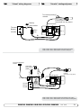
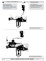
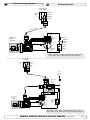
Thruster installation
• Fjern alt materiale som
etter boring,av
slik
at17hullet
6.2.7
Monta
• uten
Leggbo
p
• Prøvemonter braketten provisorisk
tilpasses boremalen og passer til thruster braketten.
•
Bolten
med
en
fres
eller
fil
om
nødvendig.
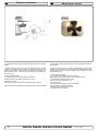
Mark the centreline of the tunnel and the boats centreline.
For å plassere girhuset riktig må du først markere tunnelens, og
• Støvsug
og materialrester.
There must be no casting where the motor bracket
is to be og tørk bort støv
• der
Bruk v
båtensenterlinje på tunnelen. Tunnelen må ha en jevn overflate
• Fjern boremalen før installasjon.
placed.
braketen skal festes.
presse
Hull for
innsetting av undervannshus
The darkest grey area shown on the installation template is the con1. De mørke6.2.5
grå områdene
på installasjonsmalen
viser kontakt- •
Trekk
6.2.4 Before
Hullinstalling
for thruster brakettens
festebolter
tact area for the bracket and must not be removed.
flaten mellom braketten
og tunnelen og må ikke fjernes.
tunnel
•
Bruk
en
rundsag
beregnet
for
glassfiber
med k
the bracket, clean and dry the contact area to achieve optimal con2. Før
braketten monteres
rengjøres
kontaktflaten
på
tunnelen
slik
atFjern
det and
De
4
hullene
til
brakettens
festebolter
skal
bores
med
Ø
9
mm
•
den
thruster
modell
som
skal
monteres.
Det
tact for the sticker. (Fig. 1)
oppnås maksimal kontakt. (Fig. 1) Fest installasjonsmalen eksakt over
bore/skjære
medlittlav
hastighet.
(11/32”)
bor. line and
Stick the installation template sticker exactly
over the centre
senterlinjene. Propellen
kan monteres
til siden
for båtens senterlinje
6.2.7
Montasje(Fig.
av 1)Thrusteren
festebolterkan monteres
cross line. ( The propeller may be mounted slightly offset) The bow
dersom dette
er hensiktsmessig.
i en S
• NB!
thruster may be mounted at any angle, from 0° - 90° Installation from
vinkel mellom 0°- 90°i forhold Thruster
til horisontallinjen. Mellom Hullsag
45° og horison(Ø) f
være
•
Legg
på
anbefalt
tetningsmasse
i
hullene
Testmontasje (I)
45° to hozontal requires a support for the6.2.6
motor. ( Fig.2)
tal må motor ha ekstra støtte. XF20
(Fig. 2).
Ø 35 mm
(1
”)
Benytt
• Boltene må festes fra utsiden av• tunnelen
Warning!
ADVARSEL!
XF40R
• Prøvemonter braketten
provisorisk uten bolter.
Fin-juster hullet Ø 54 mm (2 ”)
Brukstøttet
vedlagt
• The motor has to be properly supported
• Motor må være•skikkelig
for å avstandsmutter,
unngå påkjenning påtilhørende
tunnel ved s
XF60R
Ø 54 mm
(2 ”)
nødvendig.
to offload weight and tension on tunnel/transom. med en fres eller fil om
montering
mellom 45°presse
og horisontal
linjen. festeboltene som vist på b
på
plass
Ø 67 mm (2 ”)
XF75R
Pre.drill
3. Forhåndsboring •
Trekk XF90R
til mutteren forsiktigØslik
bolten
fe
67 at
mm
(2 ”)
• All marked holes must be pre-drilled Ø2.0 mm (1/16")
• Alle punkter markert med O må
forhåndsbores
tunnellen.
• Use a centre punch prior to drilling. (Fig.3)6.2.5
med
Ø
2,0
mm
(1/16”)
bor.
Merk
først
av
punktet
Hull for innsettingmed
avenundervannshus
• Fjern deretter avstandsmutteren, skiven o
dor. (Fig.3)
Drilling holes for the bracket bolts
•
Bruk
en
rundsag
beregnet
for
glassfiber
med korrekt
dimensjon
iht.
• The bracket holes must be drilled Ø 9 mm (11/32") (Fig.4)
4. Hull for thruster brakettens festebolter.
De 4 hullene
til
XF
Rev: festebolter
6, 2010-01-01
•
brakettens
skal
bores
med
Ø
9
mm
(11/32”)
bor.
(Fig.4)
•
NB!
Sett
inn
de
ytterste
gjengene
på bolte
den
thruster
modell
som
skal
monteres.
Det
anbefales
å
Drilling the insertion hole
Use a saw drill designed for glass fibre cutting, with the
5. lav
Hullhastighet.
for hullsag av undervannshus
være
fett
på
på
kontaktflaten
mellom
bolte
bore/skjære
med
6.2.7
Montasje av festebolter
correct size according to the thruster model
to be fitted.
• Bruk en rundsag beregnet for glassfiber med korrekt dimensjon iht. den
•
Benytt
13
mm
fastnøkkel
til
å
trekke
til
og
6.2.8 med
Test
Slow speed is recommended. (Fig.5)
thruster modelli hullene
som skal monteres.
Det anbefales å bore/skjære
lavm
• Legg på anbefalt tetningsmasse
for boltene.
Thruster hastighet. (Fig.5) Hullsag (Ø)
Insert hole before final filing. (Fig. 6)
• Monte
• Boltene må festes fra utsiden av tunnelen (innvendig i båten).
før 35
tilpassing.
(Fig.6)
mm (1
”)
XF20 6. Innføringshull Ø
Remove excess material
nødve
• Bruk vedlagt avstandsmutter, tilhørende skive og mutter M8 til å
Use a file or cutter to even out the edges of the hole
7. Fjern alt materiale
som
er til (2
overs
Øvist
54
mm
”)etter boring, slik
XF40R
bolteh
presse
på
plass
festeboltene
som
på
bildet.
Use a vaccum cleaner to clean up.
at hullet til passes boremalen og passer til thruster
XF60Rforsiktig
54ogmm
(2 ”)
• Ikke m
Trekk til mutteren
slik Støvsug
at Ø
bolten
fester
hullet
i
Remove the sticker before installation. (Fig.7) •
braketten.
tørk
bortseg
støviog
materialrester.
Ø før
67installasjon.
mm (2 ”)
• Propel
tunnellen. XF75R Fjern boremalen
Test mounting - 1
Test installation of the bracket provisionally ( without
the
bolts)
8.
Testmontasje
-1
Ø
67
mm
(2 ”)
XF90R
i konta
• Fjern deretter avstandsmutteren, skiven
og M8
mutteren.
to ensure optimal adjustment. Trim the hole with a file if nec
Prøvemonter braketten provisorisk uten bolter.
essary. (Fig 8).
Fin-juster hullet med en fres eller fil om nødvendig.
NB! Sett inn de ytterste gjengene på bolten med fett. Det skal ikke
6.2.8 boltens
Test montasje
(II)
Rev: 6, 2010-01være fett på på kontaktflaten XF
mellom
hode og tunnelen.
Rev: 6, 2010-01-01
Side 17
• Benytt 13 mm fastnøkkel til å trekke• til og
festethrusterenheten
M8 boltene.
Monter
og propellen prov
nødvendig å dreie propellen slik at denne
EB 20/110 S - EB 40/160 S - EB 60/160 S - EB 75/185 S - EB 90/185
S 1.0.6innvendig
- 2014 i tunnelen.
boltehodene
• Ikke monter medbringer-pinnen, skive og
•
XF
12
•
•
•
Fig. 9
Sikaflex-291
Würth
• Fjern deretter avstandsmutteren, •skiven
og M
Würth Kleb og Tett 0890100 eller tilsvarende.
• NB! Br
NB! Bruk ikke tetningmasse som
og blir
ved herding.
• stivner
NB! Sett
innhard
de ytterste
gjengene på bolten
Fig. 10
Fig.være
11 fett på på kontaktflaten mellom boltens
Benytt 13 mm fastnøkkel til å trekke til og fes
6.2.7 Montasje av festebolter
6.2.10 Tetnin
6.2.10
Tetningsmasse
påføres
• Legg
på anbefalt tetningsmasse
i hullene for boltene.
6.2.11 Montasje av XForce thrusteren • Påfør t
•• Boltene
må festes fra på
utsiden
av tunnelen
(innvendig
i båten).ikke
Påfør tetningsmasse
braketten
og boltene
slik at lekkasje
kan op
• Monter
thrusterenhet/brakett
kan oppstå.
• Bruk
vedlagt avstandsmutter, tilhørende
skive
og mutter M8 til å og sett propelle
• vist
Ikke
presse på plass festeboltene som
påmonter
bildet. medbringer-pinnen, skiven og m
ennå.
• Trekk til mutteren forsiktig slik at bolten
fester seg i hullet i
• Monter skiver og låsemuttere til braketten og
tunnellen.
moment
vekselvis
mellom boltene.
• Fjern deretter avstandsmutteren, skiven
og M8
mutteren.
• Låsemutterne trekkes til med moment: M8: C
6.2.8• Sjekk
Test montasje
(II)roterer uten å komme i ko
at med
propellen
• NB!
på bolten
fett. Det
skal ikke
Fig. 12
Fig.
13 Sett inn de ytterste gjengene
• Monter
og propellen
proviso
6.2.11 Monta
være fett på på kontaktflaten mellom
boltensthrusterenheten
hode og tunnelen.
6.2.11
Montasje
av
XForce
thrusteren
•
Stryk
ut
tetningsmassen
slik
at
overflaten
bli
nødvendig
å
dreie
propellen
slik
at
denne
ka
• Benytt 13 mm fastnøkkel til å trekke til og feste M8 boltene.
• Monter
boltehodene
innvendig
i
tunnelen.
• Monter thrusterenhet/brakett og sett propellen på plass.
• Ikke m
Ikke og
monter
medbringer-pinnen,
skiveennå.
og pro
• Ikke monter medbringer-pinnen,• skiven
mutteren
til propellen
•
Propellen
skal
kunne
rotere
fritt
innvendig
it
ennå.
• Monter
i
kontakt
med
denne.
• Monter skiver og låsemuttere til braketten og trekk til med jevnt
momen
moment vekselvis mellom boltene.
• Låsem
• Låsemutterne trekkes til med moment: M8: Ca. 20 Nm
• Sjekk a
XF • Sjekk at propellen rotererRev:
uten6,
å 2010-01-01
komme i kontakt med tunnelen.
6.2.12 Montasje av propell • Stryk u
•
Stryk
ut
tetningsmassen
slik
at
overflaten
blir slett og jevn.
6.2.8 Test montasje N
(II)
GB
• NB! Symmetrisk
Montering av Thruster
fortsetter 4 bladers kapla
Thruster installation continues
glassfiber
acetal (POM
• Monter thrusterenheten og propellen provisorisk. Det kan forsterket
være
9. Apply suitable marine sealant in holes for bolts. Fastening
of
9.
Montasje
av
festebolter
nødvendig å dreie propellen slik at denne kan passere
bolts must be done from the outside of the tunnel ( inside boat).
Legg på anbefalt tetningsmasse •i hullene
for boltene.
Monter
medbringer pinnen (4) i h
boltehodene
innvendig
Use the spaceer/nut, the washer and the M8 nut as shown
in the
Boltene måi tunnelen.
festes fra utsiden av tunnelen (innvendig i båten).
(5).
Sett
påmutter
plass M8
propellen (3), 6
picture to press in the bolts. (Fig.9)
Bruk vedlagt avstandsmutter,
skive ennå.
og
• Ikke monter medbringer-pinnen,
skive ogtilhørende
propellmutter
propellen
med
låsemutter
(1). Ko
til
å
presse
på
plass
festeboltene
som
vist
på
bildet.Trekk
• Propellen skal kunne rotere fritt innvendig i tunnelen uten å kommetil
NB: Carefully grease the upper part of the threads. Do not grease
mutteren forsiktig slik at bolten fester pinnen
seg i hullet
ier
tunnellen.
(4)
på
plass
i
sporet
ip
denne.
the contact area between the bolt head and the tunnel.i kontakt med Fjern
deretter avstandsmutteren, skiven og M8 mutteren. (Fig.9)
trekkes til.
6.2.
Tighten the nut carefully so that the bolts attach to the tunnel
and Montasje
NB! Sett inn
ytterste gjengene på bolten med fett. Det skal ikke
6.2.12
av de
propell
thenn remove the spacer/nut, the washer and nut.
være fett på på kontaktflaten mellom boltens hode og tunnelen.
XF
Rev: 6, 2010-01-01• NB! Symmetrisk 4 bladers
Sidei 18
kaplan
propell
produsert
• Trekk
til propell
mutteren
glassfiber
10. Use a 13 mm spanner to tighten up the M8 bolts. (Fig. 10)
10. Benyttforsterket
13 mm fastnøkkel
å trekke tilatogpropellen
feste M8 boltene.
•acetal
For(POM).
åtilforhindre
roterer når mutte
(Fig.10)
kan propellen låses med et kosteskaft el lign
Test mounting -2
• Monter
medbringer
(4) i hullet i propellakselen
Propellmutteren
trekkes til med moment:
• Test mount the bracket and propeller provisionally. The propeller
Test montasje
-2 •pinnen
Sett påthrusterenheten
plass propellen
skive (2) og
M6:
Ca. 68 mm
Nmprovisorisk.
may need to be turned while being mounted because of the bolts (5).
• Monter
og (3),
propellen
Detfest
kan være
protruding in the tunnel.
nødvendig
å dreie
propellen
slik
at
denne
kan
passere
boltehodene
propellen
med
låsemutter
(1).
Kontroller
at
medbringer
M8: Ca. 20 Nm
• Make sure that the propeller rotates freely in the tunnel.
innvendig
i tunnelen.
pinnen
(4) er
på plass i sporet i propellen før mutteren
• Do not install the driving pin, washer and locking nut yet.
• Ikke monter medbringer-pinnen, skive og propellmutter ennå.
trekkes
til. skal kunne rotere fritt innvendig i tunnelen uten å komme
• Propellen
•
Specified sealants:
• Sikaflex-291,
•
• Würth Sealant 0890100 or similar.
• Important: Do not use sealant of hard caulk type.•
i kontakt med denne.
• Trekk t

Trekk til propell
mutteren
Anbefalt
tetningsmasse
• For å fo
• Sikaflex-291
For å forhindre
at propellen roterer når mutteren skal trekkes til,
kan pro
Würth Kleb og Tett 0890100 eller tilsvarende.
kan propellen••låses
medikke
et kosteskaft
el som
lign.stivner og blir hard ved herding.
XF
Rev:
6, 2010-01-01
• Propell
11. Apply sealant
NB! Bruk
tetningmasse
• Make
Propellmutteren
trekkes til med moment:
• Apply suitable sealant to the bracket and the bolts.
sure
M6: Ca
leakage is impossible. (Fig.11)
M6: Ca. 8 Nm11. Tetningsmasse påføres
M8: Ca
• Påfør tetningsmasse på braketten og boltene
M8: Ca. 20 Nm
12. Install the EB thruster
slik at lekkasje ikke kan oppstå (Fig. 11).
• Install the bracket and turn the propeller into place. Do not install
• the driving pin, washer and locking nut yet.
12. Montasje av EB thrusteren
• Mount the washers and lock nuts and fasten with even turns in
• Monter thrusterenhet/brakett og vri propellen på plass.
succession making sure that the propeller can rotate freely all the
• Ikke monter medbringer-pinnen, skiven og mutteren til propellen
time.
ennå.
• ( Locking nut torque, M8: ab. 20 Nm) (Fig.12)
• Monter skiver og låsemuttere til braketten og trekk til med jevnt
XF mellom boltene.
Rev: 6, 2010-01-0
moment vekselvis
Rev: 6, 2010-01-01
19
13. XF
Make surfaces even
• Låsemutterne M8 trekkes til med moment: Ca. 20Side
Nm (Fig.12)
• Smooth out the sealant in order to make surfaces even. (Fig.13)
• Sjekk at propellen roterer uten å komme i kontakt med tunnelen.

13.• Stryk ut tetningsmassen slik at overflaten blir slett og jevn.
(Fig.13)
EB 20/110 S - EB 40/160 S - EB 60/160 S - EB 75/185 S - EB 90/185 S
1.0.6 - 2014
13
Propeller installation
GB
Låsemutterne trekkes til med moment: M8: Ca. 20 Nm
Sjekk at propellen roterer uten å komme i kontakt med tunnelen. 6.2.12
N
Montering av propell
•
Stryk ut tetningsmassen slik at overflaten blir slett og jevn.
•
•
•
•
Fig. 2
Fig. 1
• Trekk til p
• For å forh
NB! Symmetrisk 4 bladers kaplan propell produsert i
kan prop
glassfiber forsterket acetal (POM).
• Propellm
M6: Ca. 8
Monter medbringer pinnen (4) i hullet i propellakselen
M8: Ca. 2
(5). Sett på plass propellen (3), 6 mm skive (2) og fest
propellen med låsemutter (1). Kontroller at medbringer
pinnen (4) er på plass i sporet i propellen før mutteren
trekkes til.
6.2.12 Montasje av propell
•
•
•
•
•
XF
Trekk til propell mutteren
XF
Rev: 6, 2010-01-01
For å forhindre at propellen roterer når mutteren skal trekkes til,
kan propellen låses med et kosteskaft el lign.
Propellmutteren trekkes til med moment:
M6: Ca. 8 Nm
M8: Ca. 20 Nm
Rev: 6, 2010-01-01
Side 19
1. Symmetrical 4 blade kaplan propellers. Glass fibre reinforced acetal
(POM).
1. Symmetrisk 4 bladers kaplan propell produsert i glassfiber forsterket
acetal (POM).
• Install the driver pin (4) into the hole in the propeller shaft ( 5). Fit the
propeller ( 3) making sure that the driver pin is located properly into the
groove in the propeller. Fit the washer ( 2) and fasten the propeller ( 3)
with the locking nut ( 1). Locking nut torque, M6: ab. 8 Nm and M8: ab.
20 Nm.) ( Fig. 1)
• Monter medbringer pinnen (4) i hullet i propellakselen (5). Sett på plass
propellen (3), 6 mm skive (2) og fest propellen med låsemutter (1). Kontroller at medbringer pinnen (4) er på plass i sporet i propellen før mutteren trekkes til. (Fig.1)
2. Fastening the propeller
Use a piece of wood ( e.g broomstick) to prevent the
propeller rotating while fastening the lock nut. (Fig. 2)
Apply bottom coating
All wet parts in the tunnel must be covered with bottom coating.
NB: Ensure that the installation has no leaks when the boat is set afloat.
14
2. Trekk til propell mutteren
• For å forhindre at propellen roterer når mutteren
skal trekkes til, kan propellen låses med et kosteskaft el lign.
• Propellmutteren trekkes til med moment:
M6: Ca. 8 Nm M8: Ca. 20 Nm (Fig. 2)
Legg på bunnstoff
• Alle områder som kommer i kontakt med saltvann
skal behandles med relevant bunnstoff.
• NB! Kontroller at det ikke er noen form
for lekkasjenår båten sjøsettes.
EB 20/110 S - EB 40/160 S - EB 60/160 S - EB 75/185 S - EB 90/185 S
1.0.6 - 2014
Electrical installation
GB
Elektrisk installasjon
N
Important regarding EB 20!
This should be run with the same amount of break time as running
time. Max cont. running time is 30 seconds. Example: run 10 seconds, wait 10 seconds or run for 20 seconds, wait 20 seconds, etc.
Maximum cable length 1
Minimum cable dimension
Viktig angående EB 20!
Denne skal kjøres med like lang pausetid som driftstid.
Max kont. kjøreperiode er 30 sek. Eksempel: kjør 10 sek,
vent 10 sek eller kjør 20 sek, vent 20 sek, osv.
Reguired min. battery capacity
Anbefalt min. batteri kapasitet
Maksimum kabel lengde 1
Minumum kabel dim.
XF
Thruster
Motor V/
kW
Thrust (KG)
Skyvekraft
Length
Lengde
Dim. 2 mm2 - AWG
Ah/V
CCA ( SAE)
Rec. fuse amp.
Anbefalt sikr. amp.
EB 20
12/1.6
20
1-5
50-1/0
60 Ah/12V
550
150
EB 40
12/2
40
1-4
4-8
50-1/0
70-2/0
115 Ah/12V
800
250
EB 60
12/5.0
60
1-10
10-20
95-3/0
120-4/0
115Ah/12V
800
325
EB 60
24/5.0
60
1-10
10-20
95-3/0
95-3/0
115Ah/24V
800
250
EB 75
12/6.0
75
1-10
10-20
95-3/0
120-4/0
115Ah/12V
800
325
EB 75
24/6.0
75
1-10
10-20
95-3/0
95-3/0
150Ah/24V
1050
325
EB 90
12/6.5
90
1-10
10-20
95-3/0
120-4/0
115Ah/12V
800
325
EB 90
24/6.5
90
1-10
10-20
95-3/0
95-3/0
150Ah/24V
1050
325
1) The distance from the thruster unit to the battery, one way, each able. Use of even larger cable dimensions and battery capacity will give the thruster better performance.
2) Wiring insulation rating is 105oC ( 221oF) minimum.
1) Avstanden mellom thruster enheten og batteri, en vei for hver kabel ( sum av plusskabel og minuskabel). Ved å benytte kabler med enda større tverrsnitt vil det oppnås økt
skyvekraft.
2) Skyvekraft er oppgitt ved 10,5V (21V) driftspenning.
3) Krav til kabelisolasjon er minimum 1050C (221oF).
EB 20/110 S - EB 40/160 S - EB 60/160 S - EB 75/185 S - EB 90/185 S
1.0.6 - 2014
15
GB
Electrical installation
• Explanation of electrical table
- All cable lengths are the total of + and - (to and from).
- Battery size is stated as minimum cold crank capacity, not Ah.
- Use slow fuse rated to hold stated Amp-Draw for min. 5 minutes.
* Cable size and main battery size when an extra bow battery with
minimum the CCA mentioned as A is installed.
• It is important that you use a good cable size and batteries with a
high cranking capacity to feed the thruster, because it is the actual
voltage at the motor while running the thruster that decides the
output rpm of the motor and thereby the actual thrust. Please see
the list below for advised min. sizes of cables and batteries. You can
of course use larger cables for even better results.
• A main switch (*C) that can take the load without noticeable voltage
drop must be installed in the main positive lead so the power for the
thruster can be turned off independent of the rest when not on board
or in emergencies. This should be placed in an easy accessible
place and the boats instructions should inform that this should be
turned off like the boat’s other main switches.
• We also advice to install a fuse (*D) in the positive lead for protection
against short circuiting of the main cables. This fuse should be of a
adequate quality which normally means that it is physically large as
these have less voltage drop than the simple / small ones. It should
be of the slow type and sized to take the amperage draw for at least
5 minutes.
• A circuit breaker can be used instead of the fuse and main power
switch as long as the functionality is the same.
• The cable ends must be fitted with terminals and these must be well
isolated against contact with anything but the proper connection
point.
• Terminals must be properly tightened. Tighten with max: 15 Nm/11lb/
ft.The negative/
minus cable connects to the A1 (-) terminal. The positive/plus
cable connects to the “+” terminal.
For EB 40 - 60 - 75 - 90:
N
•
•
•
•
•
•
•
Elektrisk installasjon
Forklaring til elektrisk tabell
- Kabellengder tilsvarer + kabelen, og - kabelen (Frem og tilbake).
- Min. batterikap. som kaldstartkapasitet (CCA), ikke Ampere.
- Bruk trege sikringer for å forebygge spenningsfall.
Det er viktig å bruke kabler som er store nok, og et batteri med god kaldstartkapasitet for å drive thrusteren. Det er Volten som kommer frem
til motoren under kjøring som bestemmer turtallet til motoren og dermed
også skyvekraften. Vær vennlig og jamfør listen over for minimum
anbefalte kabel, og batteristørrelse.
En hovedstrømbryter (*C) som ikke medfører stort spenningsfall må
installeres på thrusterens plusskabel. Det bør være mulig å skru av
strømmen til thruster uavhengig av resten av det elektriske systemet,
når man ikke er om bord, eller i et nødstilfelle. Bryteren bør plasseres
på et tilgjengelig sted, og båtens instruksmanual må ta for seg at denne
skal skrus av slik som de andre hovedbrytere.
Det må installeres sikring på pluss strømkabelen for å beskytte mot
kortslutning av hovedstrømkablene. Sikringen bør være av høy kvalitet,
noe som vanligvis betyr at de er fysisk store, for å unngå spenningsfall
som ofte er resultatet av å bruke mindre, enklere sikringer. Sikringen
skal være en treg type som tåler amper trekket til elektromotoren i
minimum 5 min.
En kretsbryter kan erstatte sikringen og hovedstrømbryteren hvis den
har de samme funksjonene.
Kabelendene må påmonteres terminaler og disse må isoleres mot alt
som ikke er riktig kontaktpunkt.
Det er viktig att kabelsko trekkes korrekt fast på koblingsbolt. For EB 40
- 60 - 75 - 90: Minus kabelen A tilkobles A1 (-) terminalen.
Pluss kabelen B tilkobles "+" terminalen.
EB 20 M6 Mutter, trekk til med 7 Nm
For EB 40 - 60 - 75 - 90, Mutter M8, trekk til med 10 Nm.
NB! Very important to check the following with
mainswitch in off position:
NB! Viktig!
After all electrical connections have been completed check with an
ohm meter that there is no electrical connection between electromotor body and positive terminal on the motor and between the
electromotor body and the negative (A1) terminal on the motor.
If you feel unsure on how to perform this check, contact skilled
Etter ferdig elektrisk installasjon. Sjekk med et ohm-meter at det
ikke er forbindelse mellom motorgods og B+ terminal, og mellom
motorgods og Bo- terminal ( A1).
16
EB 20/110 S - EB 40/160 S - EB 60/160 S - EB 75/185 S - EB 90/185 S
1.0.6 - 2014
GB
Control panel and control-leads
Kontrollpanel og kontrollkabler
N
P in 2
3
4
4
3
1
2
2
1
M
12 or 24V
P in 4 P in 2
P in 3
S ID E P O W
T H R U S T E R
O N
P in 3
E R
O N
S ID E P O W
T H R U S T E R
O F F
O N
S L E IP N E R
O N
P in 4
E R
O F F
S L E IP N E R
Control panel installation:
Kontrollpanel installasjon:
•
All standard Sidepower control panels of 1999 models and later can be used in any combination as well as any two way
switching device when installed with an ON/OFF switch that
breaks control power to this switch.
• Alle standard ”Sidepower” panel for 1999 modeller og senere kan
brukes i enhver kombinasjon med hverandre.
•
You can install as many panels as you wish by using optional
Y-connectors. If two or more panels are operated at the same
time in opposite directions, the electronic control box will stop the
thruster until it only receives a signal to go in one direction.
• Det er mulig å installere så mange kontrollpanel som ønskelig ved å
bruke ”Sidepower” Y-stykker.
• When using original Sidepower equipment it is all “plug & go”.
• If the drive direction of the thruster is the opposite of what
expected, the blue and grey wire must be changed on the thruster
solenoid.
• All controls must have spring load for automatic return to neutral
position.
• The mechanical installation of the panel is described in the
manual following the panel.
• The thruster control should be placed in a position were it is easy
to use, and it is very common to use the thruster at the same
time as your gear/throttle lever so it is normally a user friendly
solution to be able to access these with one hand for each
control.
Pin configuration of 4 pole AMP contact:
Pin1: BLACK
=Negative
Pin2:
BLUE
=
Engages thruster SB solenoid
Pin3:
GREY
=
Engages thruster Port solenoid
Pin4:
RED
=
Positive voltage for control panel
• Alle fireleders, toveis kontrollbrytere kan også brukes hvis de er utstyrt
med en ”av og på” bryter som bryter strømmen til bryteren.
• Hvis thrusteren skulle motta flere forskjellige signaler samtidig så kutter
den til den mottar kun et signal fra et kontrollpanel.
• Ved bruk av Sidepower originalutstyr er alle elektriske kontakter klare til
å plugges i sammen.
• Hvis kjøreretningen ikke stemmer overens med forventningene må blå
og grå ledning på Thruster-releet byttes om.
• Alle paneler må ha et fjær oppheng som gjør at de automatisk hopper
til nøytral posisjon etter bruk.
• Monteringsveiledning for panelet følger panelet.
• Thrusterpanelet bør monteres et sted det er lett å bruke. Siden gass og
gir ofte brukes samtidigt som thrusteren, er det ofte en god løsning å ha
muligheten å operere disse med hver sin hånd.
Pinne konfigurasjon for fireleder AMP kontakt:
Pinne 1: Svart
= Minus
Pinne 2: Blå
= Aktiverer thruster rele Styrbord
Pinne 3: Grå = Aktiverer thruster rele Babord
Pinne 4: Rød
= Pluss til kontrolpanel
EB 20/110 S - EB 40/160 S - EB 60/160 S - EB 75/185 S - EB 90/185 S
1.0.6 - 2014
17
GB
"Visual" wiring diagrams
"Visuelle" koblingsskjemaer
N
EB 20 connected to manual main switch.
EB 20 koblet til manuell hovedbryter.
EB 20 connected to automatic main switch.
EB 20 koblet til automatisk hovedstrømbryter.
18
EB 20/110 S - EB 40/160 S - EB 60/160 S - EB 75/185 S - EB 90/185 S
1.0.6 - 2014
"Visual" wiring diagrams
"Visuelle" koblingsskjemaer
N
N
EB40 - EB60 - EB75 - EB90 connected to manual main switch.
EB40 - EB60 - EB75 - EB90 koblet til manuell hovedbryter.
GB
(mounted in a dry place)
EB40 - EB60 - EB75 - EB90 connected to automatic main switch.
EB40 - EB60 - EB75 - EB90 koblet til den automatiske hovedbryteren.
EB 20/110 S - EB 40/160 S - EB 60/160 S - EB 75/185 S - EB 90/185 S
1.0.6 - 2014
19
Technical wiring diagrams
N
Koblingsskjemaer
Viktig angående EB 20!
Denne skal kjøres med like lang pausetid
som driftstid. Max kont. kjøreperiode er 30
sek. Eksempel: kjør 10 sek, vent 10 sek
eller kjør 20 sek, vent 20 sek, osv.
Important regarding EB 20!
This should be run with the same
amount of break time as running.
Max cont. running time is 30 seconds. Example:
run 10 seconds, wait 10 seconds or run for 20
seconds, wait 20 seconds, etc.
GB
GB
EB20 connected to manual main switch.
EB20 koblet til manuell hovedbryter.
20
EB 20 connected to automatic main switch.
EB 20 koblet til automatisk hovedstrømbryter.
EB 20/110 S - EB 40/160 S - EB 60/160 S - EB 75/185 S - EB 90/185 S
1.0.6 - 2014
Technical wiring diagrams
Koblingsskjemaer
N
(Mounted in a dry place.)
EB40 - EB60 - EB75 - EB90 connected to manual main switch.
EB40 - EB60 - EB75 - EB90 koblet til manuell hovedbryter.
GB
(Mounted in a dry place.)
EB40 - EB60 - EB75 - EB90 connected to automatic main switch.
EB40 - EB60 - EB75 - EB90 koblet til den automatiske hovedbryteren.
EB 20/110 S - EB 40/160 S - EB 60/160 S - EB 75/185 S - EB 90/185 S
1.0.6 - 2014
21
GB
Checklist
N
Sjekkliste
Propeller is fastened correctly to the shaft.
Propellen er festet til akselen på korrekt vis.
Propeller turns freely in tunnel.
Propellen roterer fritt i tunnel.
Anti-fouling have been applied to the gearhouse and propeller
Bunnstoff er påført girhus og propell.
The brush springs are fitted correctly on the brushes in the electromotor. Does not apply to EB 20.
Børstefjærene er riktig plassert mot børstene. Gjelder ikke EB 20.
Correct drive direction as per controlpanel.
Alle elektriske koblinger er rene, tørre og tette. Korrekte kabler,
sikringer og hovedstrømsbryter er brukt.
All electrical connections are clean, dry and tight, and the correct
cable, fuse and main switch sizes have been used.
With a ohm meter check that there is no electrical connection
between electromotor body and positive/negative terminals on the
motor. Does not apply to EB20.
Kontrollpanel gir korrekt kjøreretning på thrusteren.
Boltene som holder girhus til tunnel er dratt korrekt til
Boltene som holder motor til girhus er festet korrekt.
The bolts holding the gearhouse to the tunnel are tightened correctly.
The bolts holding the electromotor to the gearhouse are tightened
correctly.
The thruster has been installed as per the instructions in this
manual and all points in checklist above have been controlled.
Thrusteren er installert i henhold til instuksene gitt i denne
manualen, og alle punkter i sjekklisten er kontrollert.
Signed: ................................................ Date:...............................
Signatur: ...............................................
Extra pre-delivery tests by installer/yard who does not use other
quality control systems !
Anbefalt før leverings test for installør / verft som ikke bruker andre
kvalitetskontroll systemer!
Thruster type: .................................................. Voltage: ....................
Thrustertype: ................................................ Volt: .............................
Serial number: ................................. Date of delivery: .......................
Serienummer: .....................................................................................
Correct drive direction as per control panel: .....................................
Leveringsdato: ....................................................................................
Voltage at thruster when running: ......................................................
Korrekt kjørerettning per kontrollpanel: ..............................................
Battery cable size used: .....................................................................
Spenning målt på thruster under kjøring: ...........................................
The compartment where the thruster is fitted is isolated from general bilge
water and has no obvious or suspected risks for flooding.
Strømkabler: .......................................................................................
Skottet hvor thrusteren er montert er isolert fra kjølvann og har ingen
åpenbar risiko for lekkasje.
Other comments by installer:
22
Dato: ................................
Kommentar fra installør:
EB 20/110 S - EB 40/160 S - EB 60/160 S - EB 75/185 S - EB 90/185 S
1.0.6 - 2014
GB
Important user precautions
• Ensure that you know the location of the main battery switch that
disconnects the thruster from all power sources (batteries) so that
the thruster can be turned off in case of a malfunction.
• Always turn the main power switch off before touching any part of
the thruster, as an incidental start while touching moving parts can
cause serious injuries.
• Always turn the control device off when the thruster is not in use.
• The maximum continues usage time of the electrical thruster is
approximately 3 minutes. The electromotor has a built in thermal
cut-off switch that will shut off the electromotor if it is overheating
and re-engage it when it has cooled down some. This should be
considered when planning your maneuvering.
IMPORTANT RELATED to EB 20: This must be run with the
same amount of subsequent rest period as driving period.
Max continuous run time is 30 seconds. Example: run for 10 seconds.
and take 10 seconds. break etc.
• This also means that the thruster will limit its total running time per
time period so that you can not count on the thruster to hold you
in a current and side wind for extensive time periods. Depending
on the surrounding temperatures etc. the thruster will be able to
run approximately 10 % of the time.
• Never use a thruster close to somebody in the water, as the
thruster will draw objects close by into the tunnel and contact with
the rotating propellers will cause serious injuries.
• With the boat on land, only run the thruster for a fraction of a
second, as without resistance it will accelerate very fast to a
damaging rpm. Also, while the thruster is in air, make sure that the
propellers have come to a complete stop before performing a
directions change of the thruster, as it might cause damage to the
thruster.
• If the thruster stops giving thrust while the electromotor is running,
chances are that there is a problem in the drive-system. You must
then immediately stop trying to run it, and turn it off, as running the
electromotor for more than a few seconds without resistance from
the propeller, can cause serious damage to the electromotor.
• When leaving the boat always turn off the main power switch for
the thruster.
• We advice to always keep the main engine(s) running while using a
thruster. This will keep the batteries in a good charge condition. This
will also give better performance to the thruster, as a higher voltage at
the thruster results in a higher torque (power) in the electromotor.
• Please note that the performance of a thruster strongly depends on
the voltage available at the electromotor. This voltage will decrease
by time because aging batteries have a reduction of capacity. By
installing new batteries the effect of the thruster should be back at
the original level.
• Make sure that only one control is used at the same time, if two
panels are operated in opposite directions at the same time the
thruster will not run at all. If they are operated in the same direction
the thruster will run in this direction.
• If the thruster is not performing or functioning as usual, the cause for
this must be found and corrected as soon as possible so to avoid
causing any other or further damage to the equipment. You must
also turn off the main battery switch immediately in case the
problem is of electric origin.
• Never store anything (e.g. equipment, sails, ropes etc.) in the
same compartment as the thruster. When the thruster runs for
a longer period it will get hot and will cause damage.
N
•
•
•
•
Viktige brukerforebehold
Forviss deg om at du kjenner plasseringen av hovedstrømsbryteren
til baugthrusteren, som kutter all strøm til thrusteren, så thrusteren
kan skrus av i nødstilfelle.
Før berøring av noen del av thrusteren må alltid strømmen skrus av.
En tilfeldig start kan volde stor fysisk skade.
Skru alltid av kontrollpanelet etter bruk.
Den maksimale sammenhengende kjøretiden for en elektrisk thruster
er ca. 3 min. da vil en føler automatisk skru av motoren når den når
en viss varme. Dette må tas i betraktning når en manøver planlegges.
VIKTIG VEDR. EB 20: Denne må kjøres med like lang påfølgende
hvileperiode som kjøre periode. Maks kontinuerlig kjøreperiode
er 30 sek. Eksempel: kjør i 10 sek. og ta 10 sek. pause osv.
•
•
•
•
•
•
•
•
•
Dette betyr at ved manøvere som tar lang tid vil ikke thrusteren
kunne brukes hele kontinuerlig. Ved manøvere som tar lang tid kan
man bruke thrusteren i ca 10 % av tiden, avhengig av tempraturen i
vannet.
Bruk aldri thrusteren når noen er i vannet, thrusteren vil trekke gjenstander til seg og kontakt med propellen vil volde alvorlig skade.
Kjør aldri thrusteren i mer enn 1 sek. når båten er på land. Uten motstand fra vannet vil thrusteren nå ødelegende turtall svært fort.
Hvis thrusterne stopper å gi skyvekraft mens motoren er i gang, er
det trolig oppstått problemer i girsystemet. Stopp umiddelbart å kjøre
motoren, og skru den av. Uten motstand fra vannet vil thrusteren nå
ødelegende turtall svært fort.
Når man forlater båten skal alltid hovedstrømsbryteren slås av.
Vi anbefaler å ha motoren i gang når thrusteren kjøres. Da vil batterien vedlikeholdes, og det vil være høyere spenning til elektromotoren.
Høyere spenning gir høyere turtall og bedre ytelse.
Ytelsen til en baugthruster avhenger av hvilken spenning motoren
mottar under kjøring. Kapasiteten til batterier avtar etter hvert som de
blir eldre, og dermed også ytelsen til thrusteren. Ved å installere nye
batterier vil thrusteren yte maksimalt igjen.
Kun en kontroll skal brukes av gangen, hvis to kontroller brukes motsatt vei vil thrusteren stoppe automatisk. Hvis to paneler opereres
samme vei vil ikke dette skje.
Hvis thrusteren ikke fungerer tilfredsstillende må feilen lokaliseres
og rettes så snart som mulig, for at ikke thrusteren skal ta ytterligere
skade, skru av hovestrømsbryteren hvis feilen er av elektrisk art.
EB 20/110 S - EB 40/160 S - EB 60/160 S - EB 75/185 S - EB 90/185 S
1.0.6 - 2014
23
GB
To turn panel ON
Turn boat to port
To turn panel OFF
Turn boat to starboard
How to use Sidepower thrusters
Howto
to use
use a bowthruster
How
bowthruster
Turn main
main power
power switch
(Always
turn
offoff the
1.1.Turn
switchfor
forthe
thebowthruster
bowthrusteron.
on.
(Always
turn
main
the main
power
switch
when
onboard.)
power
switch
when
notnot
onboard.)
2. Please take some time to exercise thruster usage in open water
2. Please
someto
time
toboat.
exercise thruster usage in open water to
to avoidtake
damages
your
avoid damages to your boat.
3. Turn the control panel on by pushing both “ON” buttons on the
3. Turn
theSidepower
control panel
by pushing Ifboth
“ON”type
buttons
on the
original
panelon
simultaneously.
another
of control
Sidepower
simultaneously.
another type of control
original
is installed,
engage panel
the On/Off
switch for theIfbowthruster.
installed,
engage
the On/Off
switch
the bowthruster.
4.isTurn
the bow
in the desired
direction
by for
pushing
the red button for
port movement
thedesired
green button
for starboard
movement.
If you for
4. Turn
the bow inor
the
direction
by pushing
the red button
port
havemovement
a joystick control,
move button
it in thefor
direction
you wish
the bowIf you
or the green
starboard
movement.
have
to move.
Other control,
controls move
like footswitches
or toggle-switches
on bow to
a joystick
it in the direction
you wish the
move.
the throttle
can
be used.
These
are normally
installed, on the
Other
controls
like
footswitches
or logically
toggle-switches
throttle
so by engaging
the port
control,
bow goes
port etc.installed,
In case ofso by
can be used.
These
arethe
normally
logically
engaging
any doubts,
in open
waters
thetryport
control,
thefirst.
bow goes port etc. In case of any
try in
waters first.
5.doubts,
Depending
onopen
the sideways
speed of the bow, you must
disengage the control device shortly before the bow is in the
5. Depending on the sideways speed of the bow, you must disengage
desired direction, as the boat will continue to move after stopping
the control device shortly before the bow is in the desired direction,
the bowthruster.
as the boat will continue to move after stopping the bowthruster.
How to use a single stern thruster
How to use a single stern thruster
Some boats might however have installed a single stern thruster
Some
because
of space
the bow.
In this a
case
the stern
stern thruster
boats
mightlimitation
howeverin have
installed
single
because
thruster is
in limitation
the same in
way
a single
bow
thruster
(seethruster
ofused
space
theas
bow.
In this
case
the stern
isabove)
moving
theway
boat’s
used for
in the
same
as stern.
a single bow thruster (see above) for
moving
the
boat’s
stern.
How
to use
a bow
and
stern thruster combined
The
combination
of
a
and
stern thruster
offers total
How to use a bow andbow
stern
thruster
combined
manoeuvrability to the boat and the opportunity to move the bow
The
and the
stern separately
each
other.
Thisthruster
enables you
to total
combination
of afrom
bow
and
stern
offers
manoeuvrability
move the boat sideways
in both
directions
and to turn
boat
to the boat
and
the opportunity
to the
move
the bow
and
around
its own
axis staying
at the
same
place.
the stern
separately
from
each
other.
This enables you to move
the boat sideways in both directions and to turn the boat around its
axis
at the
same
place.
• own
Again,
if instaying
doubt, try
in open
water
first!
Bow+Stern
Thruster
N
D
Benutzung
von Sidepower
Hvordan bruke
SidepowerThrustern
thruster
Hvordan bruke
en baugthruster
Benutzung
einer
Bugschraube
1. Die
SkruBugschraube
på hovedstrømmen
av hovedstrømmen
når duDen
ikke er
1.
über (skru
derenalltid
Hauptschalter
einschalten.
om bord i båten).
Hauptschalter
immer ausschalten, wenn niemand an Bord ist.
2. Nehmen
Det er fordel
de etwas
prøver Zeit,
baugthrusteren
på offenem
åpent vann
den første
2.
Sieom
sich
um sich auf
Gewässer
gangen.
mit
der Steuerung der Bugschraube vertraut zu machen.
3. Original
Skru på kontrollpanelet
ved å trykke
begge ”on” knappene
3.
Sidepower Panels
durch inn
gleichzeitiges
Drücken på
der
Sidepower
panelet.
Hvis annet
en originalt
panel brukes
dette
"ON"
Knöpfe
einschalten.
Falls
eine anderes
Panel må
verwendet
skrus den
på. On/Off Schalter für die Bugschraube einschalten.
wird,
4. Den
Snu baugen
ønsket
retning ved
å trykke bewegen;
rød knapp for
og
4.
Bug in idie
gewünschte
Richtung
rotbabord,
/ Backbord
grønn knapp
for styrbord.
Hvis dugrün
har joystickpanel
må stikka
Knopf
für Richtung
Backbord,
/ SteuerbordsåKnopf
für
dyttes i denSteuerbord.
retning baugen
vendes. eines Joystick Panels,
Richtung
Bei skal
Verwendung
Andre kontrollenheter
som fotbrytere,
brytere på
gass hendel kan
dieses
in die gewünschte
Richtungeller
bewegen.
Kontrollpanels
ogsåFußbrukes.
er vanligvis
logiskebenfalls
installert verwendet
og lette og operere.
wie
undDisse
Kippschalter
können
werden.
Ved tvilsind
lønner
det seg og prøve
på åpent
vann først.
Diese
normalerweise
logisch
installiert,
d.h. der Bug folgt
entsprechenden
Panelvorgabe.
Bei Unklarheit,
zunächst
5. der
Avhengig
av hvor stor fart
baugen får sideveis
må thrusteren
stoppes
auf
offenem
ausprobieren.
før baugen
er Gewässer
i riktig posisjon,
dette fordi baugen vil fortsette sideveis
litt etter thrusteren
av.
5. Abhängig
von derskruses
Geschwindigkeit,
mit der sich der Bug seitwärtsbruke
bewegt,
muß die
Steuerung bereits vor Erreichen des
Hvordan
en enkel
hekkthruster
Endpunktes aufhören, da sich der Bug noch etwas in die
Enkelte båter vil av plassmessige, eller andre hensyn bare installere
entsprechende Richtung "nachbewegt".
en hekkthruster. I disse tilfeller brukes hekkthrusteren på samme
Benutzung
Heckschraube
måte someiner
baugthrusteren.
Einigebruke
Schiffe
haben
aufgrund von
Platzmangel im Bug stattHvordan
hekk
og baugthruster
kombinert
dessen eine Heckschraube installiert. In diesem Fall ist die
Kombinasjonen av baug og hekkthruster gir en total kontroll over
Heckschraube wie eine Bugschraube (siehe oben) zu verwenbåtens bevegelser p.g.a. muligheten til å bevege hakken og baugen
den,
um das Heck zu bewegen.
uavhengig av hverandre. Båten kan skyves sidelengs og dreies rundt
Gemeinsame
Benutzung von Bug- und Heckschraube
sin egen akse.
Die
Kombination
vonåBugHeckschraube
• Det er også her fordel
prøveund
ut systemet
på åpentbietet
vann.die unabhängige Manövrierbarkeit von Bug und Heck. Dies eröffnet die
Möglichkeit, das Boot seitwärts in beiden Richtungen oder auf
der Stelle um die eigene Achse zu bewegen.
• Bei Unklarheit, zunächst auf offenem Gewässer ausprobieren.
• Again, if in doubt, try in open water first!
38
24
SP 30 S2i / SP 40 S2 i/ SP 55 Si 3.5 - 2005
EB 20/110 S - EB 40/160 S - EB 60/160 S - EB 75/185 S - EB 90/185 S
1.0.6 - 2014
GB
Maintenance
N
Vedlikehold
The belt drive usually requires no maintance. To inspect the belt,
the belt cover must be removed.
Drivremmen krever normalt ikke vedlikehold. Inspeksjon
av drivremmen krever at dekselet fjernes.
NB: EB 40: Remove the lock plug on both sides of the cover
before removing the belt cover. Replace the opposite way.
NB: EB 20, EB60, EB 75, EB 90 and: Snap off/on
the belt cover.
NB! EB 40: Fjern låsepluggen på begge sider av dekselet
og demonter dekselet. Monter i motsatt rekkefølge.
NB! EB 20, EB60, EB75 og EB90: “Snap off/on” dekselet.
Inspect the belt
Make sure that no teeth are damaged or worn.
Correct tension is when the belt can be twisted about 45 degrees.
If adjustment is reguired, loosen the 4 flange bolts and increase
the tension by adjusting the bolt under the motor (EB20 has
4 nuts). Tighten the flange bolts (or nuts) and rechecj the belt
tension.
Kontroller at ingen av drivremmens “tenner” er skadet eller slitt.
Drivremmen er passe stram når den kan vris ca. 450.
Dersom justering er nødvendig, kan de 4 boltene som fester
motoren løsnes( For EB20: 4 muttere). Stram eller slakk
justeringsbolten under motoren. Stram deretter til motorboltene
og etterkontroller drivremmen.
Periodic inspection of gearhousing and metal parts
is necessary to detect and initate action to avoid
corrosion damages.
» Retighten the bolts holding the gearhouse to the motor
bracket during the first on-land service with the specified bolt
tightening force (see page 13).
» Keep the propeller and gearhouse clean from growth by
painting with antifouling before every season.
» As a part of the seasonal service of your boat, and before
every season, always check that:
» Etterstram boltene som holder girhuset sammen med braketten
ved første på-land servicen med oppgitt moment (s. 13).
» Hold propellen og girhuset fritt for algevekst ved å påføre
bunn-stoff før hver sesong.
» Som en del av det periodiske vedlikeholdet av din båt,
og før hver sesong må følgende ting sjekkes:
• Propellen sitter godt festet.
• The propeller is securely fastened
• Boltene som holder elektromotoren til braketten sitter.
• The bolts holding the electric motor to the
motor bracket are fastened correctly.
• Skottet der baugpropellen er montert skal være rent, og
tørt. Hvis det er vann i skottet må lekkasjen finnes og tettes.
• The area where the thruster is installed is clean and dry.
If there are signs of water you must try to find the source
and eliminate it.
• Alle elektriske tilkoblingspunkter er rene, og godt festet.
• All electrical connections are clean and fastened firmly.
• Make sure that your batteries are in a good condition
so that the thruster gets a good voltage. Old or bad batteries
will give a reduced performance from the thruster.
• Pass på atbatteriene er i god stand så det kan gi høy
spenning til thrusteren. Redusert spenning vil gi redusert
effekt på thrusteren.
EB 20/110 S - EB 40/160 S - EB 60/160 S - EB 75/185 S - EB 90/185 S
1.0.6 - 2014
25
Trouble shooting
GB
Before seeking assistance at the help desk of your Sidepower dealer/distributor please perform these tests and make notes of all
measurements to ensure that they have as much information as possible to work on.
NB! All check points and solutions must be carried out after consulting the relevant information elsewhere in this manual to understand how the system is intended to work. If you are unable to understand what to check, you must consult a professional.
Solution
Check
»
»
»
»
The electromotor runs, but there is no thrust.
The drive pin my be broken.
Check the drive pin and replace if necessary.
Are the propellers in the tunnel fastened correctly on the
prop-shaft (key/drive pin present)
Re-fasten or replace the propeller and/or key/drive pin.
Belt defectet.
Replace belt.
The thruster does not start at all or works only in one direction.
Check that the voltage of the electromotor is correct for
your installation by their labels.
If wrong, contact your dealer or distributor to obtain parts with the correct voltage.
Check the voltage at the thruster between main minus input
(A1 on motor) and main plus input point:
For the EB20: Measure inside the I-box.
The no load voltage should be:
12V system =12,7V / 24V system = 25,4 V. If below 12,3V / 24,6V your batteries are
not in a good charge state or worn out and must be recharged or replaced before trying
to run the thruster.
Check the voltage at the thruster while you are trying to
run it. Keep main engine(s) running to have continous
charge to the batteries.
If less than 8,5V at the thruster the voltage is to low for the thruster to operate correctly.
In a 24V boat the thruster will operate down to approx. 12V, but the performance will
be very bad. Find and correct the reason for this low voltage which will probably be
one or more of these points: main battery cable sizes and connections, battery size and
condition, fuse and main power switch performance.
If the main solenoids on the thruster are not even trying to
engage (clicking) they are probably not getting a "run" signal from the control system. Try to run the thruster without
the panel by directly connecting the red and the blue or the
red and the grey wires in the controlcable contact coming
from the thruster.
If the thruster runs in both directions, try the same in the connector that goes into the
back of the control panel. If it also works in this position, check the contact and wires
on the back of the panel and try to engage this again by pushing both ON buttons
simultaneously. If the panel does not turn on (see control light), measure the voltage
between the Red and the Black in the contact going into the thruster. If the voltage is
good, chances are that the panel is not working.
If it works by the thruster, and not by the panel there is a bad contact or a broken lead
the control cables between these two test points.
Measure that you have the correct voltage between the Red (+) and all the other colours in the contact. If you do not get a reading.
If the thruster does not run at all, or only in one direction in
the above tests, check the internal wiring on the thruster
motor, solenoids and electronic motor inter-face box to be
in accordance with the wiring diagram and ensure that all
connections are clean and tight.
Between main minus (A1 on motor) and the blue and the grey wire connected to the
sides of the main solenoids you should have the same voltage as between
the main battery cables on the thruster. If not, check that the internal wiring on the solenoid is ok and measure that there is contact through the magnetising spools of each
side of the solenoid (measure between the red and blue on one side, and red and grey
on the other side with an Ohm meter.). If there is no
contact between these about 5-30 ohms, the solenoid is broken and needs replacing.
The thruster has an unexpected low performance.
Check voltage at thruster when running.
If less than 10,5 V / 21V the thruster will not perform at specified effect.
Check, if possible, that all the brush-springs sits correctly
on the brushes in the electromotor.
If one or more brushes are loose/has no tension from the brush-spring, the performance will be low.
Check that the propeller, gearhouse and tunnel is free
from growth/barnacles etc.
If there is growth in the tunnel, this will disturb/block the waterflow and especially barnacles on the propeller will greatly reduce performance.
The thruster runs for approximately 0,5 seconds every 4 seconds.
Solenoid flapping, most probable cause:
low voltage.
»
Re-charge battery(ies), if this is not sufficient, replace battery(ies).
Check for bad cable connections, if necessary tighten/re-adjust connections.
Check cable size in accordance to manual.
The thruster runs for approximately 0,5 seconds every 10 seconds.
Solenoid lock-in, auto stop of thruster, auto retry every 10
seconds.
26
Shut off thruster main switch, tap slightly on the solenoid to see if it will release. Turn
on thruster main switch. If solenoid is still in lock-in mode, replace solenoid.
EB 20/110 S - EB 40/160 S - EB 60/160 S - EB 75/185 S - EB 90/185 S
1.0.6 - 2014
Problemer og løsninger
N
Før De søker hjelp hos din forhandler kan du foreta noen tester, og notere ned resultatet for at forhandleren skal ha mest mulig
informasjon til rådighet.
NB ! Alle sjekkpunktene på listen må sammenlignes med informasjon gitt tidligere i manualen for å forstå hvordan systemet skal
fungere. Hvis du ikke forstår sjekklisten eller de relevante opplysningene gitt i manualen så må De ta kontakt med profesjonell
hjelp.
Kontroller
»
»
»
»
Elektromotoren går, men det er ingen skyvekraft.
Brytepinnen mellom motoren og drivakselen
kan være ha blitt brutt av.
Sett i ny brytepinne og sjekk motorinstallasjonen.
Er propellen festet til propellakselen, og er drivpinne på
plass.
Fest eller erstatt propellen og drivpinnen.
Drivrem skadet eller røket.
Driverem skiftes
Thrusteren går bare i en retning, eller ikke i det hele tatt.
Kontroller at elektromotoren er beregnet for riktig spenning i forhold til din installasjon.
Kontakt din forhandler for å skaffe deler beregnet for riktig spenning.
Sjekk spenningen mellom positive og negative koblinger
på motoren. ( For EB 20 måles i kobl. boks)
Spenningen skal være 12,7 V / 25,4 V når thrusteren ikke kjøres.
Hvis spenningen er under 12,3 V / 24,6 V må batteriene lades, eller skiftes ut før thrusteren kjøres.
Sjekk spenningen mellom motorens negative og positive
koblinger under kjøring av thrusteren. Hold hovedmotoren
i gang for å sikre kontinuerlig ladning av batteriene.
Ved 8,5 V spenning, eller lavere vil ikke motoren kunne kjøres. En 24 V thruster vil
kunne kjøres med så lav spenning som 12 V, men skyvekraften vil ikke være merkbar.
Finn og rett opp feilen som skaper lav spenning. Feilen vil ofte være hovedstrømkablene og koblingene, Spenningsfall over sikring eller hovedstrømsbryter, batteriets
størrelse/tilstand.
Hvis hovedreleet på thrusteren ikke slår inn i det hele tatt
(det skal klikke når du prøver å kjøre thrusteren), så er det
et tegn på at det ikke får signal fra kontrollpanelet. Prøv
da å kjøre thrusteren uten panelet ved å koble Rød og
Blå, eller Rød og Grå kabel sammen på kontrolpanelkabelen som kommer fra thrusteren.
Hvis thrusteren kjører i begge retninger prøv samme framgangsmåte på koblingen som
går inn bak på kontrollpanelet. Hvis thrusteren fungerer må koblingene og kontaktpunktene på kontrollpanelet sjekkes. Prøv panelet igjen ved å trykke inn begge ON knappene samtidig. Hvis panelet ikke fungerer (sjekk kontroll lyset mellom ON knappene)
må spenningen mellom Rød og Svart ledning som går inn i panelet kontrolleres.. Hvis
spenningen er bra er trolig panelet defekt.
Hvis du får motoren til å kjøre ved thrusteren men ikke ved panelet så er problemet
dårlig kontakt, eller ledningsbrudd.
I tilfelle thrusteren ikke går i det hele tatt, eller bare i en
retning i de tidligere testene: sjekk at koblinger gjort på
elektromotoren, rele og forsinkelsesrele er i henhold til
koblingskjema, og at alle kontakter sitter godt, og er rene.
Spenningen målt mellom hovedstrøms minus (A1 på motor), og blå eller grønn ledning
på releet skal være lik spenningen mellom de to hoved batterikablene på thrusteren.
Hvis spenningen ikke er riktig, må det kontroleres at det er kontakt mellom de magnetiske spolene på hver side av releet (mål mellom rød og blå på motsatte sider, og rød og
grå på motsatte sider, med et OHM-Meter).
Hvis det ikke er kontakt mellom disse ( ca. 5-30 ohm. ) må releet skiftes ut.
Thrusteren yter mindre en ventet.
Mål spenningen på motoren under kjøring.
Er spenningen lavere en 10,5V / 21V vil thrusteren sunke i turtall og skyvekraften
senkes.
Hvis mulig: Sjekk at alle børstefjærene ligger riktig an mot
børstene.
Thrusteren vil ha lav skyvekraft hvis en eller flere børster ikke får trykk fra fjærene.
Kontroller propell, girhus og tunnel, og fjern eventuell
algevekst og lignende.
Algevekst i tunnelen vil redusere vannstrømmen, algevekst på propellen kan redusere
ytelsen betydelig.
Trøsteren kjører i ca. 0,5 sekunder hvert 4 sekund.
Relé ”slår / klapprer” – forårsakes som oftest av for lav
spenning .
»
Løsning
Batterilading er nødvendig – eventuelt bytt ut defekte batterier.
Kontroller alle kabeltilkoblinger for dårlig kontakt – sørg for god kontakt.
Kontroller at kabler har riktig tverrsnitti henhold til manual.
Trøsteren kjører i ca. 0,5 sekunder hvert 10 sekund.
Relèet er brent fast – Automatisk stopp av trøster. Forsøker reststart av trøster hvert 10 sekund for å se om feilen
er rettet.
Bryt hovedstrømmen til trøster med hovedstrømsbryteren og dunk forsiktig på relé for
å se om kontaktflatene slipper. Slå på hovedstrømbryter og se om feilen er fikset. Om
den vedvarer må relé byttes.
EB 20/110 S - EB 40/160 S - EB 60/160 S - EB 75/185 S - EB 90/185 S
1.0.6 - 2014
27
GB
Warranty statement
1.The equipment manufactured by Sleipner Motor AS (The “Warrantor”) is warranted to be free from defects in workmanship and materials under normal
use and service.
2.This Warranty is in effect for of two years from the date of purchase by the user. Proof of purchase must be included, to establish that it is inside the
warranty period.
3.This Warranty is transferable and covers the product for the specified time period.
4.In case any part of the equipment proves to be defective, other than those parts excluded in paragraph 5 below, the owner should do the following:
(a) Prepare a detailed written statement of the nature and circumstances of the defect, to the best of the Owner’s knowledge, including the date of
purchase, the place of purchase, the name and address of the installer, and the Purchaser’s name, address and telephone number;
(b) The Owner should return the defective part or unit along with the statement referenced in the preceding paragraph to the warrantor,
Sleipner Motor AS
or an authorized Service Centre, postage/shipping prepaid and at the expense of the Purchaser;
(c) If upon the Warrantor’s or Authorized Service Centre’s examination, the defect is determined to result from defective material or workmanship, the
equipment will be repaired or replaced at the Warrantor’s option without charge, and returned to the Purchaser at the Warrantor’s expense;
(d) no refund of the purchase price will be granted to the Purchaser, unless the Warrantor is unable to remedy the defect after having a reasonable
number of opportunities to do so. Prior to refund of the purchase price, Purchaser must submit a statement in writing from a professional boating
equipment supplier that the installation instructions of the Installation and Operation Manual have been complied with and that the defect remains;
(e) warranty service shall be performed only by the Warrantor, or an authorized Service Centre, and any attempt to remedy the defect by anyone else shall render this warranty void.
5.There shall be no warranty for defects or damages caused by faulty installation or hook-up, abuse or misuse of the equipment including exposure to
excessive heat, salt or fresh water spray, or water immersion except for equipment specifically designed as waterproof.
6.No other express warranty is hereby given and there are no warranties which extend beyond those described in section 4 above. This Warranty is
expressly in lieu of any other expressed or implied warranties, including any implied warranty of merchantability, fitness for the ordinary purposes for
which
such goods are used, or fitness for a particular purpose, and any other obligations on the part of the Warrantor or its employees and representatives.
7.There shall be no responsibility or liability whatsoever on the part of the Warrantor or its employees and representatives for injury to any person or
persons, or damage to property, loss of income or profit, or any other consequential or resulting damage or cost which may be claimed to have been
incurred through the use or sale of the equipment, including any possible failure or malfunction of the equipment, or part thereof.
8.The Warrantor assumes no liability for incidental or consequential damages of any kind including damages arising from collision with other vessels
or objects.
9.This warranty gives you specific legal rights, and you may also have other rights which vary from country to country.
28
EB 20/110 S - EB 40/160 S - EB 60/160 S - EB 75/185 S - EB 90/185 S
1.0.6 - 2014
PARTS LIST - EB20/110 S
3
1
6
2
12
10
9
11
PARTS LIST EB EB20/110 S
Ref.Descr.
EB20
1 Belt cover
114-00180
2
Motor 12V112-11012
3
I-box,complete 12V102250-12v
6
Motor cable (EB20)12-90140
7
Control box ( in i-boks)6 1232i
9 Drive pin propeller
113-00213
10 Propeller kit
55-00057
11 Belt kit, prop shaft
55-00204
12
Belt drive kit,motor shaft55-00200
EB 20/110 S - EB 40/160 S - EB 60/160 S - EB 75/185 S - EB 90/185 S
1.0.6 - 2014
29
PARTS LIST - EB 40/160 S - EB 60/160 S - EB 75/185 S - EB 90/185 S
4
1
2
12
10
11
9
PARTS LIST EB THRUSTERS
Ref.
Descr.EB40EB60EB75EB90
1
Belt cover 114-00197114-00197114-00198114-00198
2
Motor 12V 112-20112112-43012112-43012112-43012
2
Motor 24V112-43024112-43024112-43024
Brush kit,12V 112-00034112-00032112-00032112-00032
Brush kit,24V112-00033
112-00033
112-00033
4 Relay 12V
4 1472 12
4 1472 12
4 1472 12
4 1472 12
4 Relay 24V
4 1472 24
4 1472 24
4 1472 24
5
relay cover 114-00300114-00300114-00300114-00300
7 Control box
6 1232i
6 1232i
6 1232i
6 1232i
8 Motor loom
6 1278B
6 1278B
6 1278B
6 1278B
9
Drive pin propeller 113-00189113-00189113-00189113-00189
10
Propeller kit 55-0006255-0006255-0006355-00063
11 Belt kit, prop shaft
55-00205
55-00205
55-00206
55-00206
12 Belt drive kit,motor shaft
55-00201
55-00202
55-00202
55-00202
12
Belt drive kit,motor shaft EB90/2455-00203
30
EB 20/110 S - EB 40/160 S - EB 60/160 S - EB 75/185 S - EB 90/185 S
1.0.6 - 2014
Notat
EB 20/110 S - EB 40/160 S - EB 60/160 S - EB 75/185 S - EB 90/185 S
1.0.6 - 2014
31
Worldwide sales and service
SLEIPNER MOTOR AS P.O. Box 519 N-1612 Fredrikstad Norway
Tel: +47 69 30 00 60 Fax:+47 69 30 00 70 www.side-power.com [email protected]
EB20_90_v1_0_6_mars_2014
www.side-power.com