1
Application guide
BALTIC
Providing indoor climate comfort
BALTIC-AGU-0108
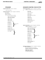
TABLE OF CONTENTS
APPLICATION
GUIDE
Ref : BALTIC-AGU-0108-E
BALTIC ™
1. EUROVENT
02
1. GENERAL DESCRIPTION
03
2. FEATURES AND BENEFITS
Standard Unit
Options and accessories 04
09
3. GENERAL DATA
Model Number Description16
Physical data & Quick Selection17
Option Specification
21
4. COOLING AND HEATING PERFORMANCES
Selection Procedure
Heating Hot Water Coil
Electric Heater
Gas Burner
Energy Recovery
5. VENTILATION PERFORMANCES
Evaporator Fan
Acoustic Data
Accessories Pressure Drop
6. ELECTRICAL DATA
Electrical Tables
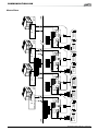
Wiring Diagrams
22
37
40
40
41
47
56
59
60
61
7. COMMUNICATION LINK
64
8. PRINCIPLE SKETCHES
73
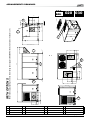
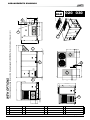
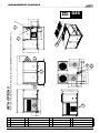
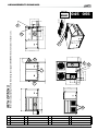
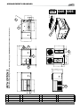
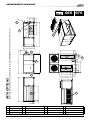
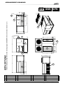
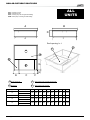
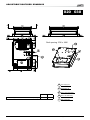
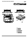
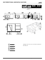
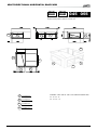
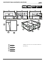
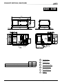
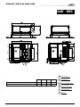
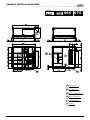
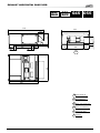
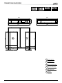
9. DIMENSIONS
Unit General Arrangement drawings
76
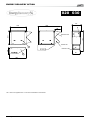
Energy Recovery module102
Weight Tables106
LENNOX have been providing environmental solutions since 1895, our range of Baltic TM rooftop continues to meet the standards that
have made LENNOX a household name. Flexible design solutions to meet YOUR needs and uncompromising attention to detail. Engineered to last, simple to maintain and Quality that comes as standard. Information on local contacts at www.lennoxeurope.com.
All the technical and technological information contained in this manual, including any drawing and technical descriptions provided
by us, remain the property of Lennox and must not be utilised (except in operation of this product), reproduced, issued to or made
available to third parties without the prior written agreement of Lennox.
Due to LENNOX on going commitment to quality, specifications subject to change without notice and without incurring liability
Application Guide • BALTIC - 0108 • •
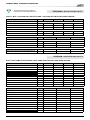
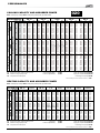
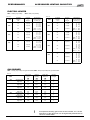
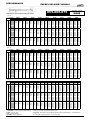
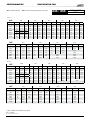
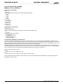
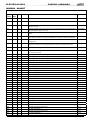
GENERAL DATA - EUROVENT CONDITIONS
All data are at Eurovent conditions.
http://www.eurovent-certification.com/
PROGRAMA
Program : Ac2-A-P-C& Ac3-A-P-C
BALTIC - BAC = Cooling only rooftop BAG = Cooling only with gas fired heating
MODEL DESIGNATION
Cooling Mode
BAC-BAG
020S
030S
035S
045S
Net cooling capacity
kW
Power input
kW
21,2
7,2
2,95
26
9,3
2,71
34,5
12,9
2,65
43,4
14,8
2,94
86
78
87
83
84
79
85
79
EER
Acoustic
Outside sound power on Standard Unit
DBA
Indoor blower outlet sound power Standard unit
DBA
MODEL DESIGNATION
Cooling Mode
BAC-BAG
055S
065D
075D
Net cooling capacity
kW
Power input
kW
51
18,5
2,76
63,6
21,9
2,9
72,5
27,4
2,64
86
84
85
82
86
85
EER
Acoustic
kW
Outside sound power on Standard Unit
DBA
Indoor blower outlet sound power Standard unit
DBA
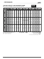
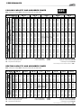
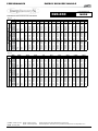
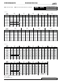
Program : Ac2-A-P-R & Ac3-A-P-R
BAH = Heat pump rooftop BAM = Heat pump rooftop with gas fired heating
MODEL DESIGNATION
Cooling mode
Net cooling capacity
Power input
EER
Heating mode
Net heating capacity
Power input
COP
Acoustic
Outside sound power
Indoor blower outlet sound power
MODEL DESIGNATION
Cooling mode
Net cooling capacity
Power input
EER
Heating mode
Net heating capacity
Power input
COP
Acoustic
Outside sound power
Indoor blower outlet sound power
• • Application Guide • BALTIC - 0108
BAH-BAM
020S
030S
035S
045S
kW
kW
20,9
7,2
2,9
24,8
9,2
2,69
34,2
12,9
2,65
43
14,8
2,91
kW
kW
20,5
6,79
3,02
24,9
8,45
2,95
35,6
11,43
3,12
43,3
13,5
3,21
dBA
dBA
86
81
87
86
85
85
85
85
BAH-BAM
055S
065D
075D
kW
kW
50,1
18,5
2,71
62,8
21,9
2,87
71,6
27,4
2,61
kW
kW
51,8
16,76
3,09
65,9
19,94
3,3
77,2
23,77
3,25
dBA
dBA
86
87
86
85
86
89
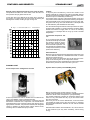
GENERAL DESCRIPTION
The BALTIC R410A range has been designed to perfectly match
light commercial applications such as offices, restaurants, shopping outlet-villages, etc.
LIFE CYCLE COST
• Compliant with EUROVENT certification program
• Copeland SCROLL compressor from maximum efficiency,
reliability and low noise
• Thermostatic expansion valves
• Alternate defrost: Heat pump have independent defrost. When
one circuit is in defrost cycle, the second is still in heat pump
mode
• Dynamic defrost : using a set of sensors, Climatic™50 detects
when coils are frozen and starts defrost cycle only when needed
• Modulating gas burner option for comfort improvement
• Heat recovery module option when high percentage of fresh
air is needed
BALTIC is available in cooling only, heat pump, gas fired or dual
fuel (gas fired and heat pump), the BALTIC range operate with
environmentally friendly R410A HFC, providing cooling capacities from 22 kW up to 76 kW in 4 different Box sizes.
• Tandem assembly for improved part load efficient and increased
operating limits
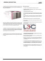
LIFE CYCLE COST COMPARATOR (L3C)
The BALTIC range as been designed to be very flexible for our
customer, it can either be extremely competitive and simple when
first cost is the main driver, but many options can be added to
make the BALTIC a Premium product.
The BALTIC range is a new generation rooftop where IAQ (Indoor Air Quality) and efficiency of the unit have been looked at
in details.
• The Life Cycle Cost Comparator is a unique software program
developed by LENNOX Europe.
• Life Cycle Costs are Initial- (unit price and installing costs),
Service- and Running costs.
• With the L3C program we are able to assist our customers
in making the right choice of units and options required for
a new project.
• The L3C program compares different Lennox units, in order
to make the best decision. It assists the choice of optimum
economical options in the units based on life cycle costs.
• Our sales engineers are more than willing to assist you in your
choice based on the best suitable solution calculated by our
L3C program.
Application Guide • BALTIC - 0108 • •
GENERAL DESCRIPTION
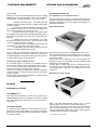
EASY TO INSTALL AND SERVICE
Handling
PLUG and PLAY Unit
All options are factory installed on the unit, which means that they
are ready for use on installation, ensuring that the time spent
on site is minimised, reducing the installation effort, which can
result in cost savings.
Bottom entry (through the base) for electrical power and Hot
Water (if option fitted) lines are available as standard.
To make installation easier, Lennox have modified the Baltic
power supply. It is not required anymore to have "neutral" hooked
up to the unit (with the only exception of the extract fan option
which requires Neutral).
Baltic should be powered by 400 V, 3phases, 50 Hz.
Circuit breakers
To improve the safety of the BALTIC and extend its life, circuit
breakers protect against over-loading, over intensity and a
disconnected supply phase. Maintenance is also improved as
there is no requirement to change fuses. The electrical panel is
manufactured in accordance with EN60204-1 (1998) electrical
directive.
Numbered wires
All wires and connectors are numbered as shown on the electrical drawing to facilitate maintenance and diagnostic.
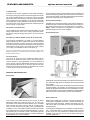
• • Application Guide • BALTIC - 0108
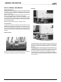
To facilitate handling and to minimise the risk of damage to the
units from site lifting and positioning, LENNOX has equipped
the BATLIC range with "retractable lifting lugs" at the bottom
of the unit.
During transportation, when minimum footprint is required, the 4
"retractable lifting lug", will be folded in the chassis. They can be
unfolded for lifting, putting all the lifting equipement away from
the casing, therefore reducing risk of damaging the casing.
For the same reason, the condenser coils are protected with an
"Aquilux" sheet, guarding them against damages that sometimes
occur in transit.
FEATURES AND BENEFITS
Air flow configuration
Unless specified otherwise when ordered, the BALTIC rooftops
are shipped with downflow configuration and with 100 Pa external static pressure at nominal air flow, and 100% return air.
However, the air flow and pressure characteristics can be set
up at the factory to your particular project requirements, that will
help reducing time spent on site.
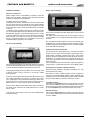
standard unit
External panels are easily removed providing clear access to
all components.
On the size 60 and 70, the compressor's box is opened thanks
to the LENNOX patented system "Hinged Access coil". This very
unique feature is giving a very good access to the 2 compressors
meantime increasing the machine compactness.
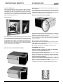
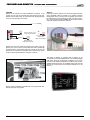
External access to the pressure gauges
Variable Pulley
For cases where the actual external static pressure or air flow
on a particular project is different from what is specified on an
order, LENNOX has enhanced the BALTIC rooftop by providing
an adjustable belt and pulley. The installer can easily and quickly adjust the air flow within a 20% window without moving the
mounted fan motors. This variable pulley provides flexibility and
peace of mind during commissioning.
Easy to access (under patent March 2004)
Measuring the low-pressure and high-pressure on a rooftop is
a basic and normal operation that Lennox wanted to make as
simple and easy for service technicians.
This is why, remote pressure taps have been made accessible
from the outside (on a post), whitout entering the refrigeration
section of the unit.
EU3 / G3 grade - Disposable Filters
Ensuring easy service and maintenance. On start-up we recommend that you change the throwaway filter for replacable
washable filters, with metal frames.
Be careful to the filter fire class related to the local rules
EXTENDED LIFE CYCLE
Assembly quality, compliance to PED 97-23, EN 60204-1,
CE, made in an ISO 9001v2000 Factory
What probably makes the difference are those small details
which have given LENNOX its reputation.
Electrical components are selected to the highest standards,
refrigeration components are generously sized to ensure maximum performance and reliability.
Quality manufacturing procedures together with a culture of
continuous improvement at all LENNOX factories, ensure the
products are built to the highest standards.
BALTIC complies to EN60204 norms, PED 97-23 directive, is CE
compliant and is built in an ISO9001v2000 certified Factory.
Application Guide • BALTIC - 0108 • •
FEATURES AND BENEFITS
Anticorrosion fixings and Anticorrosion Coating on the
casing (10 years warranty)
standard unit
Removable Aluminium Drain Pan
The BALTIC has been designed to ensure that it has a long
operational life.
The RAL 9002 powdered polyester paint is UV resistant, protecting the unit from damaging UV rays.
Further resistance is provided on the BALTIC range through
the use of anticorrosion fixings (A2 Anticorrosion) as a standard
feature.
These standard features allows LENNOX to offer a 10 year
warranty against corrosion (*).
(*) Corrosion LENNOX policy : Nevertheless the LENNOX coating is highly resistant to corrosion, the warranty will not be applied for Rooftop installed at less
than 1000 m away from the sea.
More reliable refrigeration circuit
This gives the drain pan a longer life. The underside of the unit
is insulated to reduce condensation.
The bent drain traps are shipped in a kit form. Drain pan is sloped
to prevent stagnation of water. It is removable with 2 screws.
It slides out and can be easily cleaned, preventing growth of
bacteria in the drain pan.
Accurate percentage of fresh air (under patent INPI MAY
2003)
To minimise the risk of leaks, refrigeration circuit has been drastically simplified to reduce the number joints (potential cause of
leak). For example a BALTIC BAHM40 would have only 28joints,
when a typicall rooftop of the same size would have38 joints).
The second inovation of the refrigeration circuit will reduce
maintenance time.
All joints and all pipes are located in the refrigeration section.
This includes evaporator collector located in the same compartment. Service technician only have one door to open to access
the whole circuit.
INDOOR AIR QUALITY DOES MATTER
Fire proof (M0) insulation (Indoor Air Section)
Because, for LENNOX, health and safety issues cannot be compromised, in all rooftops fire insulation (M0 fire Class) is fitted as
standard. 65 kg/m3 insulation is mechanically fitted to the unit.
This feature improves the safety of the rooftop against fire, as
the specification suggests, the insulation will not burn and smoke
is not generated.
Edges of insulation are protected on the edge to perfectly seal
the insulation.
• • Application Guide • BALTIC - 0108
Because a fresh air damper curve is not linear, it is not accurate
to assume that the percentage of opening of the damper is equal
to the percentage of fresh air enterring the building.
However, this linear control of a damper is by far the most used
in the industry.
With Indoor air quality and running cost of a building being more
important to our customer, Lennox wanted to pilot the % of fresh
air more accurately.
The CLIMATIC™ 50 can now periodically recalibrate the dampers, in calculating the real percentage of fresh air entering the
bulding for the each different positions of the damper.
This recalibration is achieved using the return air sensor, the
outdoor sensor and supply air sensor. When all heating or cooling
elements are off, the percentage of fresh air actually entering
the rooftop is the result of the following equation :
"%Fresh Air" =
"Supply Air temperature" - "Return Air Temperature"
"Fresh air Temperature " - "Return Air Temperature"
For example, CLIMATIC™ 50 would accurately adjust the damper position to get 20% fresh air and not 30% or 10%.
Therefore, this feature either saves a lot of energy cost by not
bringing more fresh air than needed or makes sure that air quality
is at the expected level.
This allows CLIMATIC™ 50 to send an alarm when damper can
not be calibrated (faulty damper )
FEATURES AND BENEFITS
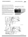
Specific case of high pressure drop in the return air duct :
The problem becomes even more critical, when the return air
duct pressure drop is greater than 50 Pa.
In this case, due to the difficulty of the return air to go back to
the rooftop, it is usual to have a lot more fresh air entering the
building than wanted, resulting in high running cost.
in return air duct, B : Low in return air duct
% fresh air ratio in the supply air
A : High
standard unit
Tandem
To improve part load efficiency, Lennox has chosen to use
tandem assembly of compressor as often as possible. Starting
from the fact that rooftop works at PART LOAD most of the time,
tandems improve considerably the efficiency.
For example, when only 50% of the load is needed, one of the 2
compressors in the tandem stops and the remaining compressor
has proportionally twice more exchanger surface to play with.
The gross COP can go from 2,95 at full load to 3,86 at part load
for size BAC045. (ARI standard 340.360-2000)
The second advantage of tandem is the improvement of operating limits with unloading. In extreme weather conditions, Baltic
R410A will continue to supply warm or cold air in unloading
compressors. For example size 45 can go up to 48°C outside
temperature.
Thermostatic Expansion Valves
As it is important that the units
operate as efficiently as possible
and achieve maximum performance at any running condition,
the thermostatic expansion valves optimise the superheat of the
rooftop and, therefore, its overall
performance efficiency.
Alternate defrost
Because, this new rooftop has been designed to reduce life cycle
cost, the alternate defrost is a standard feature with 2 circuits
heat pump rooftops (E box).
When one circuit is in defrost the other is still running in heatpump mode reducing the use of costly electric heater.
This unique feature on the market place for small rooftop makes
the BALTIC a pionneer in terms of low life cycle cost.
RUNNING COST
Scroll compressors / Refrigeration Circuits
Scroll compressors are used on the BALTIC for maximum efficiency and reliability, having overload protection.
Refrigerant circuits include compressors, condenser coils and
direct-drive condenser fans, evaporator coil and belt-driven
Centrifugal Indoor fans, expansion valves, high capacity dryers,
high pressure switches, low pressure switches, full refrigerant
charge. In addition you will find check valves, defrost control,
reversing valve on BAHM heat pump models.
Dynamic defrost (under patent INPI May 2003)
BALTIC is featuring the "dynamic defrost" concept.
Typical rooftop starts defrost cycle when the outside temperature
is below a certain value and repeat the cycle periodically.
This results sometimes in starting an expensive defrost cycle
when it is very cold outside but very dry, in other words when
the coil is not frozen.
After many test in the Lennox laboratories, it was found that
it is possible to exactly know if the coil is frozen, by analysing
the temperature difference between the coil and the outside
temperature.
With this built-in feature of the CLIMATIC™ 50, Lennox insures
to start a defrost cycle only when necessary, hence saving
energy.
Application Guide • BALTIC - 0108 • •
FEATURES AND BENEFITS
CONTROL
CLIMATIC™ ™ 50 Software (RT50)
The new generation of microprocessor based control, CLIMATIC™ 50 will equip the BALTIC rooftop range.
It inherits 15 years of technology and field operating experience
from its predecessors the CLIMATIC™1 and CLIMATIC™ 2.
LENNOX has found the latest hardware technology available on
the market place and developped a software specifically designed for rooftop applications, maximising the LENNOX rooftops
efficiency and performance.
CLIMATIC™ 50 has been thought to be more user-friendly
than CLIMATIC™ 2 and easier to understand. However CLIMATIC™ 50 has been designed to be as powerfull and even
more flexible.
CLIMATIC™ 50 provides flexibility and the ability to control
multiple rooftops on a single job site.
Enhanced with a 16 bit processor at 14Mhz and a 2 Megabytes flash memory, CLIMATIC™ 50 has been designed to save
energy and to extend the operational life of the BALTIC product
range. It will, for example, optimise the running time of each
compressor, automatically switch between compressors from
those that start first and have an anti short-cycle program. It is
able to control 34 fault signals and manage security algorithms
generating various fault signals.
In terms of comfort, CLIMATIC™ 50 provides an innovative PI
control.
CLIMATIC™ 50 looks at difference between set point and room
temperature and calculate the time needed to reach the set point
and determines the capacity required.
This innovative control, will garanty a better temperature accuracy, while saving energy in not bringing the full capacity when
not needed.
As cooling is often not the only requirement, hot water coils or
electric heaters can be provided with proportional control and
heat pump with multi step regulation is available as well.
CONTROL
As a standard feature, CLIMATIC™50 provides 4 scheduling
time zones per day on 7 days. This allows energy consumption
management according to the building use.
On each of the 4 time zones, heating set point, cooling set
point, minimum fresh air, humidity set point high and up, and
even the different authorisations for cooling and heating can be
adjusted. CLIMATIC™ 50 provides a choice of different remote
displays depending on customer requirement and application
of the system.
As a standard feature, it is possible to set alarms (adjustable
value low and high) on room temperature and humidity.
Step of heating priority
Unique feature on the market, CLIMATIC™ 50 allows the user
to decide which heating element will come first.
This works perfectly on dual fuel unit, it is possible to pioritize
heat pump mode down to an adjustable set point (for example
0°C) and switch to gas fired mode below this value.
This gives the benefits of the excellent heat pump COP when
outside temperature is not too cold and allows to use gas heating
when temperature is lower.
Flexibility
CLIMATIC™ offers incredible flexibility. For example, advanced
user can go in the heart of the regulation in deciding reactivity of
the PI algorythm or by setting supply temperature limits .They
might even decide to authorize or not some heating or cooling
device depending of the outside temperature.
Automatic summer/winter time change
CLIMATIC™ 50 offers an automatic time switch from winter to
summer. This had always been a problem in the past for customer to keep there rooftop at the right time, jeopardising all their
effort to optimize energy consumption by smart scheduling.
Noise reduction feature
During unoccupied timezone, BALTIC rooftop will work on half
of its capacity by using only half of the
compressors and half of the condensing fans (For double circuits
rooftops).
Therefore it may cycle more often but would be quieter when
running.
This option is very often used at night when capacity needed is
lower and when noise matters more.
Last 32 faults stored in the mother board
Part of the new features of CLIMATIC™50 is the storage in the
main mother board of the last 32 faults with time, date and fault
code. This can be seen with DS50 Service Display or Climalink
Climalook.. even if those were not connected when the fault
occurred.
Staggered start feature
If there is a power shortage, units will not restart at the same
time. To make this feature available, units have to be addressed
with a different number between 1 and 12. The unit will start a
number of minutes after power return depending on its address
(Address * 10 seconds).
Example, unit number 3 will start 30 seconds after power is
back.
This is a very important feature to avoid peaks of current.
• • Application Guide • BALTIC - 0108
FEATURES AND BENEFITS
options and accessories
Inter unit link
ROOFCURB AND AIRFLOW
Rooftop can now be connected together (up to 12) via a double
shielded pair of wire (not supplied by Lennox) and use different
running modes, as explained bellow, with no cost increase.
Non adjustable, non assembled roofcurb
1 : Master slave mode "total" : The master gives the
ventilation order, its set point and its room temperature/humidity
to all other rooftops.
2 : Master slave mode "temperature": The master gives
the ventilation order and its room temperature/humidity to all
other rooftops, but they have their own set point.
3 : Master slave mode "average" : The master gives
the ventilation order and theroom temperature/humidity used by
all rooftop is the average of all rooftop, each rooftop has its own
set point.
4 : Master slave mode "cooling/heating" : All rooftop
are stand-alone but the slaves have to have the same running
mode as the master (Cooling or heating).
5 : Back-up mode : One rooftop is the back-up unit and
will operate if any of the other rooftop has a failure.
6 : Rolling Back-up mode : Same as above, except the
"back-up" unit will be different each tuesday.
On top of that, the outside temperature/humidity given to all
rooftop can either be the average of rooftop or be the external
humidity/temperature of the master, making possible the use of
a single "weather station" for the whole site.
Available dry contact (4 Output /2 Input)
As a standard features, an ON/OFF and a RESET Input dry
contacts are available as well as a GENERAL FAULT output.
On top of this, 2 programmable logical inputs and 1 programmable logical ouput are available for the customer.
Input can, for example, be programmed to disable compressor
or electric heater or receive a running status from any devices
from the customer.
Ouput could be programmed to energize any customer device
or send different fault information.
A sturdy mounting frame mates to the single package unit and
provides an automatic weatherproof sealed rooftop installation.
Shipped knocked down for ease of shipping and handling, it is
easily field assembled.
Adjustable Roofcurb
Galvanized construction with mounting flange in 25/10° plate.
This adjustable roofcurb can be installed on a roof with up to
4-5% slope in all directions enabling the BALTIC to be adapted
to most roof profiles.
Each roofcurb has its supply and return openings specifically
designed to ensure that resistance and hence pressure drop
through the curb is minimised.
This may allow a smaller supply fan to be selected due to the
fact that there may be less resistance through the unit and the
roof mounting frame, compared to more traditional roof mounting frames.
Multidirectional flow roofcurb
OPTIONS
REFRIGERATION OPTIONS
LOW AMBIENT KIT
This option allows the Baltic to work in cooling mode with an
outside temperature down to 0°C (instead of 10°C in the standard
unit). This is specifically needed when free-cooling operation is
not possible.
LOW NOISE OPTION
As rooftop are often installed in a noise sensitive area, Lennox
propose a low noise option on Baltic. To achieve low noise level,
Baltic receive a higher diameter and lower speed fan as well as
a compressor jacket.
Made of the same material as the rooftop, it has a 10 years
warranty against corrosion and it is fitted with flanges (*).
It is a necessary option when customer wants to have horizontal
return and horizontal supply on the same side of the rooftop.
It is also required with exhaust fan or gravity exhaust damper
combined with horizontal flow configuration.
(*) see LENNOX corrosion policy.
Application Guide • BALTIC - 0108 • •
FEATURES AND BENEFITS
Transition Curb
According to the French regulation CH40 (Public buildings),
which says, that a gas rooftop with a burner bigger than 70 kW,
can not be installed directly on a roofcurb. Lennox has made
approved by the French minister of interior a special transition
curb including a free air ventilation of 20 cm high underneath
the Rooftop floor, located between the standard roofcurb and
the rooftop. This is a big time saver,because it allows again the
use of roofcurb on gas rooftop.
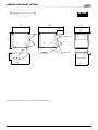
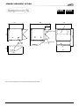
Horizontal / vertical Air Flow
Lennox believes that rooftops should be adaptable to specific
design requirements, this is why a variety of downflow return
and supply, horizontal supply and return or a mix of both are
offered.
options and accessories
The economiser is factory fitted and tested, prior to shipment and
includes 2 dampers operating from a 24V actuator. It includes a
rain hood factory fitted. Hood will be folded during transportation
to limit risk of damage and is unfolded on site.
Gravity exhaust damper
Installed with economiser assembly, gravity exhaust damper relief pressure when outside air is being introduced in the system. It
is a cheap and smart way to avoid overpressure in a building.
NOTE : When horizontal flow configuration is required, the
multidirectional roofcurb must be installed.
Power Exhaust Fan
Drive Kit up to 500 Pa (400Pa on size 20, 25, 30 and 35)
As all systems are different, it is useful to have the ability to
adapt to different air flow conditions and this can be achieved
through the selection of various choices of motors and drives
that can provide up to 500Pa at nominal air flow. This means that
commissioning on site can be done easily and quickly, helping
you to keep your installation costs to a minimum (*).
(*)
In order to minimize energy consumption and reliability, it is highly recommended by LENNOX not to oversize the ESP (external static pressure) of the
Rooftop during the selection.
Air Sock Control
The use of air socks for space conditioning allows high air
volumes to be distributed at low velocity and is becoming a
common feature in many applications. To accommodate this
trend , Airsock control is offered which allows the air socks to
be progressively filled with air on start up. BALTIC has been
enhanced with an electronic device to soft start the fan. It takes
1 minute to go from 0% of air to full air flow.
FRESH AIR AND EXHAUST AIR
Economiser
Installed with economiser assembly, it provides exhaust air pressure relief when high levels of outside air are being introduced
in the system.
Interlocked to run when return air dampers are being closed and
supply air blower is in operation. The extraction fan runs when
outdoor air dampers are at least 50% open (adjustable). It is also
overload protected. A gravity exhaust damper is supplied with this
option to prevent air from entering the unit during shutdown.
Return Roofcurb
"Free cooling" is provided through the use of fresh air where
appropriate rather than cooling the return air. The use of an
economiser is the easiest and most efficient way to modulate
fresh volumes and reduce running costs for a rooftop application, as well as improving air quality. Fully controlled by the
CLIMATIC™ 50, it is also able to ensure that minimum fresh air
is provided in line with Indoor Air Quality Regulations. Economiser operates using a "sensible" control. It is possible to prevent
the economiser from supplying air below a certain temperature
(adjustable set point, 10°C as default).
• 10 • Application Guide • BALTIC - 0108
Where system balancing is critical, it is recommended that an
exhaust fan is installed in the system. Instead of including the
exhaust fan inside the rooftop, LENNOX has designed a special roofcurb that incorporates the return fan and handles the
exhaust function.
A centrifugal fan installed with a 3rd damper (1 inside the Roofcurb + 2 inside the rooftop), is able to exhaust up to the nominal
air flow of the unit with a maximum of 300Pa static pressure
available. This roof curb can be used in either horizontal or
downflow applications.
FEATURES AND BENEFITS
options and accessories
Energy Recovery module (under patent INPI Mars 2004)
Based on the market trend to use more and more fresh air,
Lennox had to offer the possibility to recover the energy of the
exhaust air.
Made of a EUROVENT certified plate heat exchanger and a bypass damper, the heat recovery module is fully controlled by the
Climatic50. It has been designed to handle free-cooling (when
heat recovery shouldn't apply) and the exchanger is protected
against freezing of the exhaust air.
This module is fitted as a standard with G4 filters on the fresh
air section. This will protect the exchanger against outdoor dust
and increase the global filtration capacity of the machine.
The Analogic blower pressure sensor and dirty filter indication
is mandatory with that option. This will garanty a supply airflow
control and will indicate the dirtyness of Heat recovery module
fresh air filter.
This option, in addition to match Lennox commitment to a greener
planet, is a real money saving feature for the customer.
Vertical Airflow
Horizontal Airflow
Application Guide • BALTIC - 0108 • 11 •
FEATURES AND BENEFITS
INDOOR AIR QUALITY
Analogic Blower sensor and dirty filter indication
A differential pressure sensor measures the pressure drop
across the evaporator coil and filters. If this pressure drop is
above 50Pa, the rooftop is considered to be operating. The exact
pressure drop can be seen through the Intelligent CLIMATIC™
50 board. This option further improves security and reliability of
the BALTIC rooftops. It prevents overheating of any device if
the fan belt is broken.
Using the same pressure sensor as the "Blower On Sensor",
pressure drop information is interpreted by the CLIMATIC™ 50
board to determine whether the filter is dirty or not. This information is available with all CLIMATIC™ 50 controllers.
The set point between "dirty" and "clean" is fully adjustable by
the installer/users. (Default value is approximately 250Pa).
Panel filters with metal frames and disposable filter media
(EU4 / G4) (Be careful to the filter fire class related to the local
rules)
options and accessories
HEATING OPTIONS
Electric Heater
The electric heater comprises of shielded resistance heaters,
which are smooth anticorrosion tubes 6 W/cm2 capacity.
High temperature limit control offers overload protection and
is set to 90°C and located at less than 150mm after electric
heaters. This is provided as a standard feature on the electric
heater, with the electric power supply cables made of reticulated
silicon rubber, resistant to temperatures up to 200°C. For any
rooftop unit size, three sizes of electric heater are available, S
(standard), M (Medium) and H (high).
BALTIC 20 and 30 have :
Standard heat : 12 kW , 2 stages
Medium Heat : 24 kW , 2 stages
High Heat : 36 kW, Fully modulating (Triac)
BALTIC 35 have :
Standard heat : 24 kW , 2 stages
Medium Heat : 36 kW , 2 stages
High Heat : 48 kW, Fully modulating (Triac)
BALTIC 45, 55 have :
Standard heat : 27 kW , 2 stages
Medium Heat : 45 kW , 2 stages
High Heat : 54 kW, Fully modulating (Triac)
BALTIC 65, 75 have :
Standard heat : 27 kW , 2 stages
Medium Heat : 45 kW , 2 stages
High Heat : 54 kW, Fully modulating (Triac)
Capacity of the high heat heater can be limited electronically to
an exact value through the CLIMATIC™ 50.
To reduce installation time and hence cost, electric heaters are
always factory fitted, fully wired and tested, prior to shipment.
When units are installed in an environment when it is expected
that filters will be changed more frequently than usual, it is advisable that the end user includes metallic frame with washable
filter (classified EU4/G4) media. This is a more cost-effective
answer to disposable filters.
EU7 / F7 Panels filters (Be careful to the filter fire class related
to the local rules).
As different applications have differing needs, it is more and more
important that LENNOX can provide various options for a mixed
range of requirements. The EU7/F7 filter capability with EU4/G4
pre-filters is available to add additional flexibility for specific projects, where Indoor Air Quality is of particular importance.
Indoor Air Quality Sensor
Indoor air quality is controlled from the CLIMATIC™ 50 board. A
VOC (Volatile Organic Component) sensor will detect the amount
of CO2 in the air between 0 and 2000PPM. (This obviously varies
depending upon space occupancy levels). The VOC sensor will
then send a proportional signal (0-20mA) to the CLIMATIC™ 50
controller which will then modulate the fresh air.
• 12 • Application Guide • BALTIC - 0108
Hot Water Coil
Hot water coils offer fully modulating control through the use of
a 3 way valve. The hot water coil, connections and valves are
all tested at pressure of 15 bars. Frost protection is provided by
forcing the opening the 3 way valve when supply temperature
from hot water coil falls below 8°C and by stopping the outdoor
fan when that supply temperature falls below 6°C. In addition
to that, the 3 ways is also opened at 10% value if the outdoor
temperature falls below an adjustable value. Hot water coils are always factory fitted, wired and fully tested,
prior to shipment.
FEATURES AND BENEFITS
options and accessories
After extensive testing, Lennox has chosen to use Thermoguard anticorrosion cleaning for the FLEXY II. The results of
Thermoguard ® on saline test were so good, that coil can be
guaranteed against corrosion during 3 years (provided regular
maintenance is performed).
Thermoguard® treatment is available on Condensing coil, evaporator coil and hot water coil.
93% high efficiency Gas Burner Option (PCI %)
(*) see corrosion LENNOX policy.
ELECTRICAL OPTIONS
Fire-Stat
This is a thermostat that provides a signal switch off the unit,
close the fresh air damper and open the return damper when
the temperature in the return air stream is above an adjustable
set point (70°C standard).
Lennox is proud to introduce the first high efficiency gas burner
available on rooftop in Europe with 93% efficiency.
Ebox, size 60- 70, have a 92% efficient gas burner.
The standard gas burner is designed to work with 20 mbar (with
an operating range of 13-26 mbar) .
Gas module offer 2 stages of control. This assists in improving
space comfort levels by avoiding large supply air temperature
deviations.
The aluminized steel tube heat exchanger is designed to offer
maximum heat transfer efficiency.
If required, an expansion device can be provided in the BALTIC
allowing it to operate with gas pressures of up to 300 mbar. A
"propane gas" option at 37 mbar is also available.
Gas fired rooftop can not be installed inside a technical room.
TREATMENT OPTIONS
Anti-Corrosion Protection
Disconnect Switch
Main disconnect switch is lockable to increase safety around
the rooftop unit.
Switching off the unit whith the disconnect switch will reset all.
Disconnect switch will be sized accordingly to the option picked
with the unit.
The main switch is used as an emergency cut off.
It is mandatory to guarantee a proper accessibility to this
switch
Specific footbridges must be installed if the machine environment
is requiring it.
Smoke Detector
Located downstream of the filter, the optical head of the smoke
detector can detect any type of smoke. When this occurs the
unit will stop operating, the return air damper will be fully closed
and the fresh air damper will fully open while sending an alarm
signal to the unit.
In accordance with the European norm, it is also compliant with
the French regulation on public buildings.
% of mass differentiation
Mass loss in Saltspray
Fin Guard
Aluminium/ Copper
Cuivre/Cuivre
Hours
When the units are installed in potentially aggressive environments, which can often be the case for example in coastal environments, it is often a requirement that the coils are specially
treated to protect them against the corrosive effects .
Application Guide • BALTIC - 0108 • 13 •
FEATURES AND BENEFITS
CONTROL OPTIONS
options and accessories
DS 50 : Service Display
Advance control pack
Where a higher level of controllability is required to make the
Baltic even more flexible, LENNOX have compiled a pack that
includes two advanced control features.
-"Enthalpy control on economiser".
Software and its sensors will ensure that the economiser does
not use 100% fresh air if the outside air has a higher enthalpy
than the return air. This feature is relevant in regions where the
relative humidity is high or when the desired room air condition
is very dry.
- "Humidity control" software and its sensors, are able to analyze
dry and wet bulb temperatures, and therefore can control a dehumidification algorithm. This will dehumidify the air in cooling
mode as it passes through the coil, then reheating it with either
electric heater or hot water coil. If there is a need to humidify
the air, a proportional contact is now available to control a humidfierthat will be provided by the customer.
DC 50 : Comfort Display
This new service display controller directly plugs on the external
wall of the unit.
This allows service personal to set up to 90 settings, read up
to 125 variables, up to 45 faults and read the history of the last
16 faults.
This controller has been designed to be very user friendly, with
6 different keys, a 4 lignes display and this controller includes
scrolling menus and true language (no codes). It will be in English
or an other alternate language.
TCB (Thermostat Control Board)
This is a remote controller for non-technical customer. It has been
wanted to aesthetically fit inside a room and be very easy to use.
It can be installed at maximum 500 meters from the unit.
This graphical display gives information such as running mode
of the unit, status of the fan, set point, % of fresh air, outside
air temperature.
Customer can change the scheduling of the different time zone,
can modify temperature set point and % of fresh air for each
zone. Customer can also overide the scheduling in either changing the set point for 3 hours or in forcing the rooftop to unoccupied mode for 1 to 7 days. ON/OFF key is also available.
DC50 Comfort display, shows faults number when rooftop is in
the failure mode. Customer can reset fault thanks to a combination of keys.
Time and day of the rooftop can be seen and modified easily
through the DC50.
• 14 • Application Guide • BALTIC - 0108
This board has been developped for any customer who wants
to take over the control of the unit. With 6 logical inputs (Compressor stage 1 and stage 2, heating step 1 and 2, 4 way valves
and fan), this board will replace the control algorythm. However
CLIMATIC™ 50 controller will stay in charge of all safety algorythm, defrost operation or free cooling operation. All Input are
volt free contact.
This is the perfect board, to have BALTIC rooftop managed by a
zoning system, a universal thermostat or even a BMS system.
Communication interface / Modbus interface
Electronic board needed for Climalink or Climalook use. One
board required per rooftop.
This board is a well a modbus interface, which is needed for
anyone who would like a BMS system to talk to the Baltic with
"Modbus protocol". No other hardware than this board is required
to have modbus dialog. One board required per rooftop.
LonTalk® interface
This board is a LonTalk® interface, which is needed for anyone
who would like a BMS system to talk to the Baltic with «Lon protocol» with FTT10. No other hardware than this board is required
to have LonTalk® dialog. One board required per rooftop.
Bacnet® interface
This board is a Bacnet® interface, which is needed for anyone
who would like a BMS system to talk to the FLEXY II with “Bacnet
protocol» RS485.
FEATURES AND BENEFITS
- OPTIONS AND ACCESSORIES
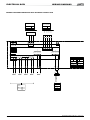
ADALINK
Adalink is the solution for HVAC installation monitoring. It can
control up to 32 units on the same site. Real gateway to the unit,
Adalink can be used locally, via LAN network or directly plugged.
It can be used remotely via modem.
1
2
32 max
3
Direct connection on PC,
using Internet Explorer®
Adalink™
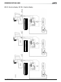
Wireless
Following customer request and last technologies development, LENNOX is able to provide you a wireless customer
display DWC 50 for your Roof Top. A repeater connected to
the main board of the CLIMATIC 50 with a RS 485 connection, communicate through a ZIGBEE protocol to the wireless
customer display located in the ambient.
or
Connection on local
area network,
using Internet Explorer®
Phone
Distant customer,
using Internet Explorer®
Adalink can show the whole site map showing status of the different units, zoom on each unit and allow the user to graphically
change set point, access alarm list, look at trend curves. It is the
ideal tools for maintenance specialist with an expert mode giving
access to all the parameters and set point of the unit.
The DWC 50 display is equipped with a battery (5 yrs
consumption) and a embedded sensor. This wireless display
wall-mount, desk-top or hand-held. In addition if you want a
more accurate ambient temperature measure in big volume,
additional wireless sensor are available and in this case the
display will communicate the average temperature of the
sensors.
Finally, yearly scheduling is possible with a very smart and userfriendly drag and drop system.
Application Guide • BALTIC - 0108 • 15 •
MODEL NUMBER DESCRIPTION
B
A
C 0200 D N M
1 M
Revision Number
B "Baltic"
F "Flexy"
A = Air-cooled
W = Water-cooled
N = No Condenser
C=cooling
H=Heat pump
G=gas fired
M=multi fuel
X=heat recovery
W=water coil
A=R22
K=R410A
M=R410A
Z=no refrigerant
H= high heat
S=standard heat
N=no heat
S= 1 circuit
D= 2 circuits
T= 3 circuits
F= 4 circuits
Cooling capacity in kW or air flow (x 1.000xm3/h)
• 16 • Application Guide • BALTIC - 0108
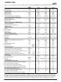
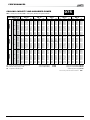
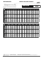
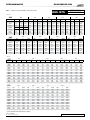
GENERAL DATA
BAC = Cooling only rooftop BAH = Heat pump rooftop BAG = Cooling only with gas fired heating BAM = Heat pump rooftop with gas fired heating
Table 1.1
Performance
Size
20
Nominal Airflow
Cooling BAC-BAG
Gross Cooling capacity (1)
Net Cooling capacity
Power input BAC
Full load amps
Direct start up amps ratio Id / Ia
COP gross BAC (3)
COP net global BAC (2)
Cooling BAH-BAM
Gross Cooling capacity (1)
Net Cooling capacity
Power input BAH
COP gross BAH (3)
COP net global BAH (2)
Heating BAH-BAM
Net heating capacity (1)
Gross Heating capacity (1)
Power input BAH
COP gross BAH (3)
COP net global BAH (2)
Part Load BAH-BAM(11)
PART Load %
Gross Cooling capacity in PART LOAD
Power input BAC in PART LOAD
COP gross cooling at part load
Heating - gaz fired
Heating capacity
Input (std heat / high heat)
Thermal efficiency
GAZ flow (for natural gaz at 20mbar and 15°C) Refrigeration circuit
Nb of Circuits x Compressor type
m3/h
3600
4500
C box
6300
KW
kW
kW
A
-
21,7
21,2
7,2
17,9
5,8
3,02
2,95
26,8
26,0
9,6
21,6
5,4
2,79
2,71
35,5
34,5
12,9
29,7
3,5
2,76
2,68
KW
KW
kW
-
21,4
20,9
7,2
2,97
2,90
25,6
24,8
9,2
2,78
2,69
35,2
34,2
12,9
2,74
2,65
KW
kW
kW
-
20,5
20,0
6,79
2,95
3,02
24,9
24,1
8,45
2,85
2,95
35,6
34,6
11,43
3,03
3,12
Expansion
Refrigerant charge per circuit Clim / PAC
Coils
Indoor Coil : Face area / nb of rows / Fin per inch
Outdoor Coil : Face area / nb of rows / Fin per inch
B box
30
35
50%
22,7
5,9
3,83
kW
kW
%
m3/h
S/H
S/H
S/H
18.6 / 30.7
20 / 33
93
1.9 / 3.2
18.6 / 30.7
20 / 33
93
1.9 / 3.2
18.6 / 42.8
20 / 46
93
1.9 / 4.5
nb x type
1xZP83KCE
nb x type
kg
SINGLE
1 x TXV
1 x 6.3
SINGLE
1 x TXV
1 x 6.3
TANDEM
1 x TXV
1 x 8.2
m2 / nb / FPI
m2 / nb / FPI
0.63 / 4 / 14
1.1 / 3 / 16
0.63 / 4 / 14
1.1 / 3 / 16
0.875 / 4 / 14
1.54 / 3 / 16
1xZP103KCE ZP72KCE + ZP72KCE
(1) All data are at Eurovent condition at 400V/3Ph/50Hz. Summer : Outdoor temperature 35°C DB / Entering coil temperature
27°C DB / 19°C WB. (2) excluding heating emission of the supply motor fan. (3) including heating emission of the supply motor
fan. Winter : Outdoor temperature 7°C DB, 6°C WB Entering coil temperature 20°C DB.(4) At nominal Airflow. (5) S = Small, H
= Hight. (6) at down return air and down supply air configuration. (7) below this value, option "Low ambiant kit" is required
Application Guide • BALTIC - 0108 • 17 •
GENERAL DATA
BAC = Cooling only rooftop BAH = Heat pump rooftop BAG = Cooling only with gas fired heating BAM = Heat pump rooftop with gas fired heating
Nominal Airflow
Ventilation data
Nominal Airflow
Minimum Airflow Maximum Airflow External static pressure / maximum (4)
Indoor fan (Centrifugal fan BAC/BAH)
Number x Drive type
Mechanical Power Input (1)
Rotation speed
Indoor fan (Centrifugal fan BAG/BAM S)
Number x Drive type
Mechanical Power Input gas -S (1)
Rotation speed
Outdoor fan (axial)
Number
Nominal Airflow
Motor power
Rotation speed
Filter (furnished standard)
Efficiency / filter class / Eurovent
Nb of filter
Filter size
Dimension
Lenght (STD / GAZ) without fresh air hood (6)
Height
Width (6)
Weight standard unit BAC
Weight gas unit
Acoustic @ 100 Pa
Outside sound power on standard unit (1)
Outside sound power on Low noise unit (1)
Indoor blower outlet sound power on standard unit (1)
Outside sound power on GAS unit (1)
Indoor blower outlet sound power on GAS unit (1)
Construction
Casing material
Min Casing thickness
Painting
Insulation Class
Cooling mode operating limits
Max. outdoor temp. at indoor 27°C DB/ 19°C WB (8)
Max outdoor temp with unloading
Min. outdoor temp. at indoor 20°C DB (7)
Max. entering indoor coil temp. at outdoor 40°C DB
Min. entering indoor coil temp. at outdoor 35°C DB
Heat pump mode operating limits
Min. outdoor temp. at indoor 20°C DB (8)
Min outdoor temp with unloading
Min. entering indoor coil temp. at outdoor 7°C DB
Size
20
m3/h
3600
4500
C box
6300
m3/h
m3/h
m3/h
Pa
3600
2900
4300
100 / 550
4500
3600
5400
100 / 550
6300
5000
7600
100 / 500
type
kW
RPM
type
1 x AT 12-9 S
0,75
740
1 x AT 12-9 S
1,10
833
1 x AT 15-11 S
1,10
678
kW
RPM
1 x AT 12-9 S
0,75
852
1 x AT 12-9 S
1,10
978
1 x AT 15-11 S
1,50
842
nb
m3/h
kW
RPM
2
8250
0,720
1430
2
8250
0,720
1430
2
10000
0,840
860
type
dB(A)
dB(A)
dB(A)
dB(A)
dB(A)
cm
type/RAL
type
30
35
80-85 % / G3 80-85 % / G3 80-85 % / G3 2
2
2+2
500 x 625 x 45 500 x 625 x 45 400 x 500 & 500
mm x mm
mm
mm
mm
kg
kg
B box
BAG S
BAG H
2017
1220
1418
394
445
454
2017
1220
1418
414
465
474
1890
1221
1915
547
608
627
S&H
S&H
86
76
78
86
81
87
77
83
87
86
84
81
82
85
85
Aluzinc
Aluzinc
Aluzinc
0,10
0,10
0,10
polyester / 9002 polyester / 9002 polyester / 9002
M0
M0
M0
°C
°C
°C
°C
°C
46
NA
14
38
20
45
NA
14
38
20
45
48
14
38
20
°C
°C
°C
-12
NA
7
-12
NA
7
-12
-15
7
(1) All data are at Eurovent condition at 400V/3Ph/50Hz. Summer : Outdoor temperature 35°C DB / Entering coil temperature
27°C DB / 19°C WB. (2) excluding heating emission of the supply motor fan. (3) including heating emission of the supply motor
fan. Winter : Outdoor temperature 7°C DB, 6°C WB Entering coil temperature 20°C DB.(4) At nominal Airflow. (5) S = Small, H
= Hight. (6) at down return air and down supply air configuration. (7) below this value, option "Low ambiant kit" is required
• 18 • Application Guide • BALTIC - 0108
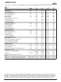
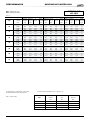
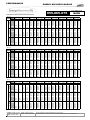
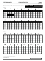
GENERAL DATA
BAC = Cooling only rooftop BAH = Heat pump rooftop BAG = Cooling only with gas fired heating BAM = Heat pump rooftop with gas fired heating
Table 1.1
Size
Size
45
Nominal Airflow
Cooling BAC-BAG
Gross Cooling capacity (1)
Net Cooling capacity
Power input BAC
Full load amps
Direct start up amps ratio Id / Ia
COP gross BAC (3)
COP net global BAC (2)
Cooling BAH-BAM
Gross Cooling capacity (1)
Net Cooling capacity
Power input BAH
COP gross BAH (3)
COP net global BAH (2)
Heating BAH-BAM
Net heating capacity (1)
Gross Heating capacity (1)
Power input BAH
COP gross BAH (3)
COP net global BAH (2)
Part Load BAH-BAM (11)
PART Load %
Gross Cooling capacity in PART LOAD
Power input BAC in PART LOAD
COP gross cooling at part load
Heating - gaz fired
Heating capacity
Input (std heat / high heat)
Thermal efficiency
GAZ flow (for natural gaz at 20mbar and 15°C) Refrigeration circuit
Nb of Circuits x Compressor type
m3/h
KW
Expansion
Refrigerant charge per circuit Clim / PAC
Coils
Indoor Coil : Face area / nb of rows / Fin per inch
Outdoor Coil : Face area / nb of rows / Fin per inch
55
65
8100
9000
11500
13500
44,7
43,4
14,8
35,7
3,4
3,03
2,94
52,6
51,0
18,5
41,6
3,7
2,85
2,76
65,4
63,6
21,8
52,4
3,7
3,00
2,92
74,4
71,6
27,4
63,3
3,2
2,72
2,62
kW
-
44,3
43,0
14,8
2,99
2,91
51,7
50,1
18,5
2,80
2,71
64,6
62,9
21,8
2,97
2,88
73,6
70,9
27,4
2,69
2,59
KW
kW
kW
-
43,3
42,0
13,50
3,11
3,21
51,8
50,2
16,76
2,99
3,09
65,8
64,0
19,84
3,23
3,32
76,9
74,2
24,07
3,08
3,20
50%
28,2
7,3
3,86
50%
33,5
8,9
3,77
50%
34,3
13,1
2,63
50%
39,4
16,5
2,40
30.7 / 55.8
33 / 60
93
3.2 / 5.7
30.7 / 55.8
33 / 60
93
3.2 / 5.7
55.8 / 111.6
60 / 120
92
5.7 / 11.5
55.8 / 111.6
60 / 120
92
5.7 / 11.5
kW
A
KW
kW
kW
%
m3/h
nb x type
nb x type
D box
E box
75
ZP83KCE + ZP83KCE ZP103KCE + ZP103KCE ZP154KCE + ZP103KCE ZP154KCE + ZP154KCE
TANDEM
1 x TXV
1 x 12.5
TANDEM
1 x TXV
1 x 12.5
m2 / nb / FPI 1.25 / 4 / 14 1.25 / 4 / 14
m2 / nb / FPI 2.2 / 3 / 16 2.2 / 3 / 16
DUAL
2 x TXV
2 x 11
DUAL
2 x TXV
2 x 11
1.7 / 4 / 14
3.6 / 3 / 16
1.7 / 4 / 14
3.6 / 3 / 16
(1) All data are at Eurovent condition at 400V/3Ph/50Hz. Summer : Outdoor temperature 35°C DB / Entering coil temperature
27°C DB / 19°C WB. (2) excluding heating emission of the supply motor fan. (3) including heating emission of the supply motor
fan. Winter : Outdoor temperature 7°C DB, 6°C WB Entering coil temperature 20°C DB.(4) At nominal Airflow. (5) S = Small, H
= Hight. (6) at down return air and down supply air configuration. (7) below this value, option "Low ambiant kit" is required
Application Guide • BALTIC - 0108 • 19 •
GENERAL DATA
BAC = Cooling only rooftop BAH = Heat pump rooftop BAG = Cooling only with gas fired heating BAM = Heat pump rooftop with gas fired heating
Size
45
Nominal Airflow
Ventilation data
Nominal Airflow
Minimum Airflow Maximum Airflow External static pressure / maximum (4)
Indoor fan (Centrifugal fan BAC/BAH)
m3/h
Number x Drive type
Mechanical Power Input (1)
Rotation speed
Indoor fan (Centrifugal fan BAG/BAM S)
Number x Drive type
Mechanical Power Input gas -S (1)
Rotation speed
Outdoor fan (axial)
Number
Nominal Airflow
Motor power
Rotation speed
Filter (furnished standard)
Efficiency / filter class / Eurovent
Nb of filter
Filter size
55
65
8100
9000
11500
14200
m3/h
m3/h
m3/h
Pa
8100
6500
9700
100 / 500
9000
7200
10800
100 / 500
11500
8600
13000
100 / 500
14200
10000
16000
100 / 500
type
kW
RPM
1 x AT 15-15 S
1 x AT 15-15 S
1,50
683
2,20
725
type
kW
RPM
1 x AT 15-15 S
1 x AT 15-15 S
2,20
851
3,00
913
2,2
801
4,0
908
nb
m3/h
kW
RPM
2
15000
1,320
850
2
15000
1,320
850
2
19000
1,500
910
2
19000
1,500
910
type
nb
mm x mm
D box
E box
75
1 x AT 15-11 G2L 1 x AT 15-11 G2L
2,20
705
3,00
804
1 x AT 15-11 G2L 1 x AT 15-11 G2L
80-85 % / G3 80-85 % / G3 80-85 % / G3 80-85 % / G3 4
4
4+2
4+2
500 x 625 x 45 500 x 625 x 45
500x600&
500x 500
500 x 600 &
500 x 500
Dimension
Lenght (STD / GAZ) without fresh air hood (6)
Height
Width (6)
Weight standard unit BAC
Weight gas unit
Acoustic @ 100 Pa
Outside sound power on standard unit (1)
Outside sound power on Low noise unit (1)
Indoor blower outlet sound power on
Outside sound power on GAS unit (1)
Indoor blower outlet sound power on GAS
Construction
Casing material
Min Casing thickness
Painting
Insulation Class
Cooling mode operating limits
Max. outdoor temp. at indoor 27°C DB/ 19°C WB (8)
Max outdoor temp with unloading
Min. outdoor temp. at indoor 20°C DB (7)
Max. entering indoor coil temp. at outdoor 40°C DB
Min. entering indoor coil temp. at outdoor 35°C DB
mm
mm
mm
kg
kg
1910
1221
2235
604
678
700
1910
1221
2235
619
693
715
2873
1225
2260
796
904
963
2873
1225
2260
852
960
1019
dB(A)
dB(A)
dB(A)
dB(A)
dB(A)
85
82
83
85
85
86
82
84
86
87
85
82
82
86 / 86
84 / 85
86
82
85
86 / 86
88 / 89
Aluzinc
0,10
cm
type/RAL
type
Aluzinc
0,10
Aluzinc
0,10
Aluzinc
0,10
polyester / 9002
polyester / 9002
polyester / 9002
M0
M0
M0
M0
°C
°C
°C
°C
°C
46
48
14
38
20
45
48
14
38
20
46
NA
14
38
20
45
NA
14
38
20
polyester / 9002
Heat pump mode operating limits
Min. outdoor temp. at indoor 20°C DB (8)
°C
-12
-12
-12
-12
°C
-15
-15
NA
NA
Min. entering indoor coil temp. at outdoor 7°C DB
°C
7
7
7
7
(1) All data are at Eurovent condition at 400V/3Ph/50Hz. Summer : Outdoor temperature 35°C DB / Entering coil temperature
27°C DB / 19°C WB. (2) excluding heating emission of the supply motor fan. (3) including heating emission of the supply motor
fan. Winter : Outdoor temperature 7°C DB, 6°C WB Entering coil temperature 20°C DB.(4) At nominal Airflow. (5) S = Small, H
= Hight. (6) at down return air and down supply air configuration. (7) below this value, option "Low ambiant kit" is required
Min outdoor temp with unloading
• 20 • Application Guide • BALTIC - 0108
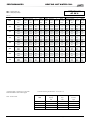
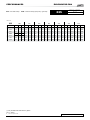
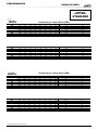
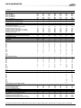
Option SPECIFICATIONS BALTIC
Table 3.3
Nominal Airflow
Heating - electric
Type of modulation
Heating capacity available
Heating capacity available
Heating capacity available
Amps S / M / H
Heating - hot water coil
Heating capacity available (1)
GAS modulating
Modulation Range
Filter
Efficiency (gravimetric) class EN779 / Eurovent
Nb of filter
Filter size
020
030
035
kW S (2)
kW M (2)
kW H (2)
A
Staged S & M
TRIAC on H
12
24
36
17 / 33 / 50
Staged S & M
TRIAC on H
12
24
36
17 / 33 / 50
Staged S & M
TRIAC on H
24
36
48
33 / 50 / 67
kW H (2)
33,7
38,4
53,5
40 - 100
40 - 100
40 - 100
90% / G4 / EU4
2
500x625x50
90% / G4 / EU4
2
500x625x50
M1
M1
90% / G4 / EU4
2+2
400x500x50
+ 500x500x50
M1
2
0,32
2
0,32
2
0,9
Yes
Yes
Yes
76
76,3
76,9
77,8
81,4
81,6
m3/h
%H
type
nb
mm
Fire class
type
Dynamic Defrost
Axial fan number
nb
kW
Motor power (total)
Soft start option : CEM - A CLASS ISO 55022 / ISO 55011
Soft Starter
Available
Acoustic low NOISE @ 100 Pa
dB(A)
Outside sound power on standard unit (1)
dB(A) S & H
Outside sound power on GAS unit (1)
3600
4500
6300
Note :
(1) Condition Entering water 90°C, Leaving water 70°C, Entering air 20°C, S = Standart heat, H = High heat
(2) not available with BAM and BAG version
(3) All data at eurovent condition at 400V/3Ph/50Hz
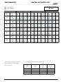
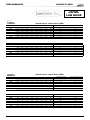
Table 3.3
3.4
Nominal Airflow
Heating - electric
Type of modulation
Heating capacity available
Heating capacity available
Heating capacity available
Amps S / M / H
Heating - hot water coil
Heating capacity available (1)
GAS modulating
Modulation Range
Filter
Efficiency (gravimetric) class EN779 / Eurovent
Nb of filter
Filter size
045
055
9000
11700
13500
kW S (2)
kW M (2)
kW H (2)
A
Staged S & M
TRIAC on H
27
45
54
38 / 63 / 75
Staged S & M
TRIAC on H
27
45
54
38 / 63 / 75
Staged S & M
TRIAC on H
27
45
54
38 / 63 / 75
Staged S & M
TRIAC on H
27
45
54
38 / 63 / 75
kW H (2)
71,2
75,5
107,6
118,1
40 - 100
40 - 100
20 - 100
20 - 100
90% / G4 / EU4
4
500x625x50
90% / G4 / EU4
4
500x625x50
M1
M1
90% / G4 / EU4
4+2
500x600x50
500x500x50
M1
90% / G4 / EU4
4+2
500x600x50
500x500x50
M1
2
1,48
2
1,48
2
1,6
2
1,6
Yes
Yes
Yes
Yes
81,9
82,1
82,1
82,6
81,9
82.2 / 82.3
82,2
82.7 / 82.9
m3/h
%H
type
nb
mm
Fire class
type
Dynamic Defrost
Axial fan number
nb
kW
Motor power (total)
Soft start option : CEM - A CLASS ISO 55022 / ISO 55011
Soft Starter
Available
Acoustic low NOISE @ 100 Pa
dB(A)
Outside sound power on standard unit (1)
dB(A) S & H
Outside sound power on GAS unit (1)
8100
065
075
Note :
(1) Condition Entering water 90°C, Leaving water 70°C, Entering air 20°C, S = Standart heat, H = High heat
(2) not available with BAM and BAG version
(3) All data at eurovent condition at 400V/3Ph/50Hz
Application Guide • BALTIC - 0108 • 21 •
PERFORMANCES
selection procedure
EXAMPLE
Step 1 : Input
Step 1
Calculate the total and sensible loads of the area to be conditioned at design conditions.
A. 32kW
B. 35°C outdoor temperature,
24°C DB, 19°C WB entering air
condition (room return air)
C. 6 300 m3/h at 200Pa
D. Economiser and 36 kW electric
heater.
A. Total cooling load in kW
B. Summer design condition
C. Air flow needed, percentage of fresh air and external static pressure (to overcome system losses, eg ductwork, diffusers.)
D. Accessories needed
Step 2 : Cooling Capacity
A. Preselect the equipment using ‘general data’ in tables 3.1-3.2 to find units close to the required capacity.
B. Size the equipment using the ‘cooling performance’ in tables 4.1-4.40 to match the cooling loads at design
conditions.
C. To establish the net capacity, the supply fan motor power should be subtracted.
Review the indoor fan performance in tables 5.1-5.20 with the required air flow and static pressure. (Do not
forget to add the pressure drop for accessories in table 5.24)
Step 3 : Heating Capacity
A. Heat pump (*)
The selection procedure is the same as that undertaken for cooling.
Preselect equipment in “General data” in tables 3.1-3.2.
Obtain the gross heating capacity at design condition (winter conditions) from tables 4.2-4.40.
Obtain the net capacity by adding the supply fan power (selected above) to the gross capacity.
B. Other Heating
Select hot water coil in tables 4.41-4.43, electric heater in table 4.44, and gas burner in table 4.45.
(*) : This procedure doesn't take into account the impact of defrost in the heating performance. Depending on
the outdoor moisture and temperature condition, the defrost operation might reduce the heat pump capacity.
Step 4 : Electrical data
Step 2
A. Table 3.1 shows that BAC 035
will give 35,2 kW gross at nominal
operating conditions.
B. Table 4.12 shows that a
BAC 035 has a gross cooling
capacity of 34,8 kW.
C. Table 5.19 shows that economiser and 36 kW electric heater
will add 36 + 88 Pa to the external
static specified, giving a total of
324 Pa.
The table 5.6 shows that fan drive
kit ‘k8’ (2,2 kW) is required for a
BAC 035 providing 6 300 m3/h at
300 Pa.
The net capacity is therefore
34,8 kW - 2,2 kW = 32.6 kW
The table 5.4 shows that fan drive
kit ‘k8’ (2,2 kW) is required for a
BAC 035 providing 6 300 m3/h
at 300 Pa.
The net capacity is therefore
35,1 kW - 2,2 kW = 32,9 kW
Data from table 6.1
A. Heat pump unit or humidity control pack.
Pa = P(Unit+Delta kit indoor optional+Extraction fan+Electric heater+gas +Delta PLn)
la = la(Unit+Delta kit indoor optional+Extraction fan+Electric heater+gas + Delta ILn)
ld/la(base) = Table 6.1
Id=la(base) x Id/la(base)+la(Delta kit indoor optional+Extraction fan+Electric heater+gas)
B. Cooling unit
P1, la1 (summer operation) = P, la(Unit+Delta kit indoor optional+Extraction fan)
P2 (winter operation) = P(0,2+kit indoor std+Delta kit indoor optional+Extraction fan+Electric heater)
la2 (winter operation) = la(0,5+kit indoor std+Delta kit indoor optional+Extraction fan+Electric heater)
Pa = max (P1; P2)
Ia = max (Ia1;Ia2)
ld/la(base)=Table 6.1
ld=la(base) x Id/la(base)+la(Delta kit indoor optional+Extraction fan+Electric heater+gas)
Step 4
A. Table 6.1 shows that an BAC
035 (cooling unit) With 36
kW Electric heater + KIT '8'
Ia1=28,9+1,4=30,3 A
P1=16,6+0,8=17,4 kW
Ia2=0,5+3,4+1,4+50=55,3 A
P2=0,2+1,9+0,8+36=38,9kW
P2>P1 so P=P2=38,9 kW
Ia2>Ia1 so Ia=Ia2=55,3 A
Id/Ia=3,1
Id=28,9x3,1+1,4+50=141 A
• 22 • Application Guide • BALTIC - 0108
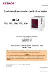
PERFORMANCES
020
COOLING CAPACITY AND ABSORBED POWER
BAH = Heat pump rooftopBAM = Heat pump rooftop with gas fired heater
Entering air temperature
4300
Maximum air flow
3600
Nominal air flow
2900
Minimum air flow
BAH-BAM 020
IDWD IDDB
16
21
24
27
30
19
24
27
30
33
22
27
30
33
36
16
21
24
27
30
19
24
27
30
33
22
27
30
33
36
16
21
24
27
30
19
24
27
30
33
22
27
30
33
36
PT
20,3
20,5
20,7
21,3
22,2
22,4
22,6
22,8
24,1
24,4
24,6
24,9
21,3
21,5
21,7
22,9
23,2
23,5
23,7
24,3
25,2
25,5
25,8
26,0
22,0
22,3
22,9
24,3
24,0
24,3
24,6
25,7
26,0
26,4
26,7
27,2
25°C
PS
13,3
16,3
19,2
21,3
13,2
16,2
19,1
21,9
13,1
16,1
18,9
21,6
14,6
18,2
21,7
22,9
14,5
18,1
21,7
24,3
14,4
18,0
21,5
24,9
15,9
20,0
22,9
24,3
15,7
19,9
24,1
25,7
15,5
19,8
24,0
27,2
PA
4,3
4,4
4,4
4,4
4,5
4,5
4,5
4,5
4,6
4,6
4,6
4,6
4,4
4,4
4,4
4,5
4,5
4,6
4,6
4,6
4,7
4,7
4,7
4,7
4,5
4,5
4,5
4,6
4,6
4,6
4,6
4,7
4,7
4,7
4,8
4,8
PT
19,5
19,7
19,9
20,6
21,3
21,5
21,7
21,9
23,1
23,4
23,6
23,9
20,4
20,6
21,0
22,2
22,2
22,5
22,7
23,4
24,1
24,4
24,7
25,0
21,1
21,3
22,1
23,4
22,9
23,2
23,5
24,8
24,9
25,2
25,5
26,2
PT Gross Total cooling / heating capacity in kW
PS Sensible cooling capacity in kW
PA Compressor absorbed power
30°C
PS
12,8
15,9
18,8
20,6
12,7
15,8
18,7
21,5
12,6
15,6
18,5
21,3
14,2
17,8
21,0
22,2
14,0
17,7
21,2
23,5
13,9
17,5
21,1
24,5
15,4
19,6
22,1
23,4
15,2
19,5
23,5
24,8
15,1
19,3
23,6
26,2
PA
4,8
4,9
4,9
4,9
5,0
5,0
5,0
5,0
5,1
5,1
5,1
5,2
4,9
4,9
5,0
5,0
5,0
5,1
5,1
5,1
5,2
5,2
5,2
5,2
5,0
5,0
5,0
5,1
5,1
5,1
5,1
5,2
5,2
5,2
5,3
5,3
PT
18,6
18,7
18,9
19,8
20,3
20,5
20,7
21,0
22,1
22,3
22,5
22,7
19,4
19,6
20,1
21,3
21,1
21,4
21,6
22,5
23,0
23,2
23,5
23,8
20,0
20,2
21,1
22,4
21,8
22,0
22,5
23,8
23,7
24,0
24,3
25,1
35°C
PS
12,4
15,4
18,4
19,8
12,3
15,3
18,3
21,0
12,1
15,2
18,1
20,9
13,7
17,3
20,1
21,3
13,6
17,2
20,8
22,5
13,4
17,1
20,6
23,8
15,0
19,1
21,1
22,4
14,8
19,0
22,5
23,8
14,6
18,9
23,1
25,1
PA
5,4
5,4
5,5
5,5
5,5
5,6
5,6
5,6
5,7
5,7
5,7
5,7
5,5
5,5
5,5
5,6
5,6
5,6
5,6
5,7
5,7
5,8
5,8
5,8
5,5
5,5
5,6
5,7
5,7
5,7
5,7
5,8
5,8
5,8
5,8
5,9
PT
17,5
17,7
17,9
18,9
19,1
19,3
19,5
20,0
20,9
21,1
21,3
21,5
18,3
18,5
19,1
20,3
19,9
20,2
20,4
21,5
21,7
22,0
22,2
22,8
18,8
19,0
20,1
21,4
20,5
20,8
21,4
22,6
22,3
22,6
22,9
24,0
40°C
PS
11,9
14,9
17,9
18,9
11,8
14,8
17,8
20,0
11,7
14,7
17,7
20,5
13,3
16,8
19,1
20,3
13,1
16,7
20,3
21,5
13,0
16,6
20,2
22,8
14,5
18,5
20,1
21,3
14,3
18,5
21,4
22,6
14,2
18,4
22,6
24,0
0,2 kW
0,4 kW
Control PA (BAC/BAH)
Control PA (BAG/BAM)
PA
6,1
6,1
6,1
6,2
6,2
6,2
6,2
6,3
6,3
6,3
6,4
6,4
6,1
6,1
6,2
6,3
6,2
6,3
6,3
6,4
6,4
6,4
6,4
6,5
6,2
6,2
6,3
6,4
6,3
6,3
6,4
6,5
6,4
6,5
6,5
6,6
PT
16,4
16,5
16,9
17,9
17,9
18,1
18,3
19,0
19,6
19,8
20,0
20,2
17,1
17,3
18,1
19,2
18,7
18,9
19,2
20,4
20,3
20,6
20,8
21,6
17,5
17,8
18,9
20,2
19,2
19,4
20,2
21,4
20,9
21,2
21,5
22,7
45°C
PS
11,5
14,4
16,9
17,9
11,4
14,3
17,3
19,0
11,2
14,2
17,2
20,0
12,8
16,2
18,1
19,2
12,7
16,2
19,2
20,4
12,5
16,1
19,6
21,6
13,9
17,8
18,9
20,2
13,9
17,9
20,2
21,4
13,7
17,9
21,5
22,7
PA
6,8
6,8
6,8
6,9
6,9
6,9
7,0
7,0
7,1
7,1
7,1
7,1
6,9
6,9
6,9
7,0
7,0
7,0
7,0
7,1
7,1
7,1
7,2
7,2
6,9
6,9
7,0
7,1
7,0
7,0
7,1
7,2
7,2
7,2
7,2
7,3
Supply fan PA (BAC/BAH) 0,65 kW
Supply fan PA (BAG/BAM) 0,88 kW
Condensing fan PA (all)
0,72 kW
Data according to Eurovent standard conditions
XXX
HEATING CAPACITY AND ABSORBED POWER
BAH = Heat pump rooftop BAM = Heat pump rooftop with gas fired heater
Dry Bulb
8°C
11°C
14°C
17°C
20°C
23°C
26°C
8°C
11°C
14°C
17°C
20°C
23°C
26°C
8°C
11°C
14°C
17°C
20°C
23°C
26°C
Entering air temperature-outdoor air temperature
3600
4300
2900
Nominal air flow
Maximum air flow
Minimum air flow
BAH-BAM 020
20°C
PT
28,0
27,6
27,2
26,8
26,4
26,0
25,6
28,6
28,2
27,8
27,4
27,0
26,6
26,1
29,0
28,6
28,2
27,8
27,4
27,0
26,6
PA
5,2
5,6
5,9
6,3
6,8
7,2
7,7
4,8
5,1
5,4
5,8
6,1
6,5
7,0
4,5
4,8
5,1
5,4
5,7
6,1
6,5
15°C
PT
25,1
24,7
24,3
24,0
23,6
23,3
22,9
25,5
25,2
24,8
24,5
24,1
23,8
23,4
25,9
25,6
25,2
24,9
24,5
24,2
23,8
PT Gross Total cooling / heating capacity in kW
PS Sensible cooling capacity in kW
PA Compressor absorbed power
PA
4,9
5,2
5,5
5,9
6,3
6,7
7,2
4,5
4,8
5,1
5,4
5,8
6,1
6,5
4,2
4,5
4,8
5,1
5,4
5,7
6,1
10°C
PT
22,3
22,0
21,7
21,4
21,1
20,7
20,4
22,7
22,4
22,1
21,8
21,5
21,2
20,8
23,0
22,7
22,4
22,1
21,8
21,5
21,2
PA
4,5
4,8
5,2
5,5
5,9
6,3
6,7
4,2
4,5
4,8
5,1
5,4
5,8
6,1
4,0
4,2
4,5
4,8
5,1
5,4
5,8
7°C
PT
20,7
20,5
20,2
19,9
19,6
19,3
19,0
21,1
20,8
20,6
20,3
20,0
19,7
19,4
21,4
21,1
20,8
20,5
20,3
20,0
19,7
PA
4,4
4,7
5,0
5,3
5,7
6,0
6,4
4,0
4,3
4,6
4,9
5,2
5,6
5,9
3,8
4,1
4,3
4,6
4,9
5,3
5,6
Control PA
Control PA (BAG/BAM)
5°C
PT
19,7
19,5
19,2
19,0
18,7
18,4
18,1
20,1
19,8
19,6
19,3
19,0
18,8
18,5
20,3
20,1
19,8
19,5
19,3
19,0
18,7
PA
4,2
4,5
4,8
5,2
5,5
5,9
6,2
3,9
4,2
4,5
4,8
5,1
5,4
5,8
3,7
4,0
4,2
4,5
4,8
5,2
5,5
0,2 kW
0,4 kW
0°C
PT
17,4
17,2
17,0
16,7
16,5
16,3
16,0
17,6
17,4
17,2
17,0
16,8
16,6
16,3
17,8
17,6
17,4
17,2
16,9
16,7
16,5
PA
4,0
4,2
4,5
4,8
5,2
5,5
5,9
3,7
3,9
4,2
4,5
4,8
5,1
5,5
3,5
3,7
4,0
4,3
4,6
4,9
5,3
-5°C
PT
15,2
15,1
14,9
14,7
14,5
14,3
14,2
15,4
15,2
15,1
14,9
14,7
14,5
14,4
15,3
15,2
15,0
14,8
14,6
14,5
PA
3,7
4,0
4,3
4,6
4,9
5,2
5,5
3,5
3,7
4,0
4,3
4,6
4,9
5,2
3,5
3,8
4,1
4,4
4,7
5,1
-10°C
PT
13,3
13,1
13,0
12,9
12,7
12,6
12,5
13,2
13,1
13,0
12,9
12,7
12,6
13,3
13,1
13,0
12,9
12,8
12,6
PA
3,5
3,7
4,0
4,3
4,6
5,0
5,3
3,5
3,8
4,1
4,4
4,7
5,1
3,3
3,6
3,9
4,2
4,6
5,0
Supply fan PA (BAC/BAH) 0,65 kW
Supply fan PA (BAG/BAM) 0,88 kW
Condensing fan PA (all)
0,72 kW
Data according to Eurovent standard conditions
XXX
Application Guide • BALTIC - 0108 • 23 •
PERFORMANCES
020
COOLING CAPACITY AND ABSORBED POWER
BAC = Cooling Only RooftopBAG = Cooling Only Rooftop with gas fired heater
Entering air temperature
4300
Maximum air flow
3600
Nominal air flow
2900
Minimum air flow
BAC-BAG 020
IDWD IDDB
16
21
24
27
30
24
19
27
30
33
22
27
30
33
36
16
21
24
27
30
24
19
27
30
33
22
27
30
33
36
16
21
24
27
30
24
19
27
30
33
22
27
30
33
36
PT
21,5
21,8
22,1
23,2
23,5
23,7
24,0
24,6
25,5
25,8
26,1
26,4
21,5
21,8
22,1
23,2
23,5
23,7
24,0
24,6
25,5
25,8
26,1
26,4
23,1
23,5
24,6
26,1
25,1
25,5
26,1
27,6
27,2
27,6
28,0
29,2
25°C
PS
14,7
18,3
21,8
23,2
14,6
18,2
21,7
24,6
14,5
18,1
21,6
24,9
14,7
18,3
21,8
23,2
14,6
18,2
21,7
24,6
14,5
18,1
21,6
24,9
17,7
22,7
24,6
26,1
17,6
22,7
26,1
27,6
17,5
22,6
27,7
29,2
PT Gross Total cooling / heating capacity in kW
PS Sensible cooling capacity in kW
PA Compressor absorbed power
PA
4,4
4,4
4,4
4,5
4,5
4,6
4,6
4,6
4,7
4,7
4,7
4,7
4,4
4,4
4,4
4,5
4,5
4,6
4,6
4,6
4,7
4,7
4,7
4,7
4,5
4,5
4,6
4,7
4,6
4,7
4,7
4,8
4,8
4,8
4,9
4,9
PT
20,7
20,9
21,2
22,4
22,5
22,8
23,1
23,8
24,4
24,7
25,0
25,4
20,7
20,9
21,2
22,4
22,5
22,8
23,1
23,8
24,4
24,7
25,0
25,4
22,1
22,5
23,7
25,2
24,0
24,4
25,2
26,6
26,0
26,4
26,7
28,2
30°C
PS
14,3
17,9
21,2
22,4
14,1
17,8
21,3
23,8
14,0
17,6
21,1
24,5
14,3
17,9
21,2
22,4
14,1
17,8
21,3
23,8
14,0
17,6
21,1
24,5
17,2
22,2
23,7
25,2
17,1
22,2
25,2
26,6
17,0
22,1
26,7
28,2
PA
4,9
4,9
4,9
5,0
5,0
5,1
5,1
5,1
5,2
5,2
5,2
5,2
4,9
4,9
4,9
5,0
5,0
5,1
5,1
5,1
5,2
5,2
5,2
5,2
5,0
5,0
5,1
5,2
5,1
5,2
5,2
5,3
5,3
5,3
5,3
5,5
PT
19,7
20,0
20,4
21,6
21,5
21,7
22,0
22,8
23,3
23,6
23,9
24,2
19,7
20,0
20,4
21,6
21,5
21,7
22,0
22,8
23,3
23,6
23,9
24,2
21,0
21,4
22,7
24,1
22,8
23,2
24,1
25,6
24,7
25,1
25,6
27,1
35°C
Control Pa (BAC/BAH)
Control Pa (BAG/BAM)
PS
13,8
17,4
20,4
21,6
13,7
17,3
20,9
22,8
13,6
17,2
20,7
24,1
13,8
17,4
20,4
21,6
13,7
17,3
20,9
22,8
13,6
17,2
20,7
24,1
16,7
21,4
22,7
24,1
16,6
21,6
24,1
25,6
16,5
21,6
25,6
27,1
PA
5,5
5,5
5,5
5,6
5,6
5,6
5,7
5,7
5,8
5,8
5,8
5,8
5,5
5,5
5,5
5,6
5,6
5,6
5,7
5,7
5,8
5,8
5,8
5,8
5,6
5,6
5,7
5,8
5,7
5,7
5,8
5,9
5,9
5,9
5,9
6,0
0,2 kW
0,4 kW
PT
18,7
18,9
19,5
20,6
20,3
20,6
20,8
21,8
22,1
22,4
22,7
23,1
18,7
18,9
19,5
20,6
20,3
20,6
20,8
21,8
22,1
22,4
22,7
23,1
19,8
20,3
21,6
23,0
21,5
21,9
23,0
24,4
23,4
23,8
24,4
25,8
40°C
PS
13,4
16,9
19,5
20,6
13,3
16,9
20,4
21,8
13,1
16,8
20,3
23,1
13,4
16,9
19,5
20,6
13,3
16,9
20,4
21,8
13,1
16,8
20,3
23,1
16,2
20,3
21,6
23,0
16,1
21,0
23,0
24,4
16,0
21,0
24,4
25,8
PA
6,1
6,2
6,2
6,3
6,3
6,3
6,3
6,4
6,4
6,4
6,5
6,5
6,1
6,2
6,2
6,3
6,3
6,3
6,3
6,4
6,4
6,4
6,5
6,5
6,2
6,3
6,4
6,5
6,4
6,4
6,5
6,6
6,5
6,5
6,6
6,7
PT
17,5
17,7
18,5
19,6
19,1
19,3
19,6
20,7
20,8
21,0
21,3
22,0
17,5
17,7
18,5
19,6
19,1
19,3
19,6
20,7
20,8
21,0
21,3
22,0
18,5
19,1
20,4
21,7
20,1
20,5
21,7
23,1
21,9
22,3
23,1
24,5
45°C
PS
13,0
16,4
18,5
19,6
12,9
16,4
19,6
20,7
12,7
16,3
19,8
22,0
13,0
16,4
18,5
19,6
12,9
16,4
19,6
20,7
12,7
16,3
19,8
22,0
15,7
19,1
20,4
21,7
15,6
20,4
21,7
23,1
15,6
20,4
23,1
24,5
Supply fan Pa (BAC/BAH) 0,65 kW
Supply fan Pa (BAG/BAM) 0,88 kW
Condensing fan Pa (all)
0,72 kW
Data according to Eurovent standard conditions
• 24 • Application Guide • BALTIC - 0108
PA
6,9
6,9
7,0
7,0
7,0
7,0
7,0
7,1
7,1
7,2
7,2
7,2
6,9
6,9
7,0
7,0
7,0
7,0
7,0
7,1
7,1
7,2
7,2
7,2
6,9
7,0
7,1
7,2
7,1
7,1
7,2
7,3
7,2
7,3
7,3
7,5
XXX
PERFORMANCES
030
COOLING CAPACITY AND ABSORBED POWER
BAH = Heat pump rooftopBAM = Heat pump rooftop with gas fired heater
Entering air temperature
5400
Maximum air flow
4500
Nominal air flow
3600
Minimum air flow
BAH-BAM 030
IDWD IDDB
16
21
24
27
30
19
24
27
30
33
22
27
30
33
36
16
21
24
27
30
19
24
27
30
33
22
27
30
33
36
16
21
24
27
30
19
24
27
30
33
22
27
30
33
36
PT
24,5
24,8
25,0
25,8
26,7
27,0
27,3
27,5
29,0
29,3
29,6
29,9
25,7
26,0
26,2
27,7
27,9
28,2
28,5
29,2
30,2
30,5
30,9
31,2
26,5
26,9
27,6
29,2
28,8
29,1
29,5
30,8
31,1
31,5
31,8
32,5
25°C
PS
16,2
19,8
23,3
25,8
16,1
19,7
23,2
26,5
15,9
19,5
22,9
26,2
17,8
22,2
26,2
27,7
17,6
22,0
26,3
29,2
17,4
21,8
26,1
30,2
19,2
24,4
27,6
29,2
19,0
24,2
29,3
30,8
18,7
24,0
29,1
32,5
PA
5,6
5,6
5,7
5,7
5,8
5,8
5,8
5,9
6,0
6,0
6,0
6,1
5,7
5,7
5,8
5,9
5,9
5,9
6,0
6,0
6,1
6,1
6,2
6,2
5,8
5,8
5,9
6,0
6,0
6,0
6,0
6,2
6,2
6,2
6,2
6,3
PT
23,5
23,8
24,0
24,9
25,6
25,9
26,1
26,4
27,7
28,0
28,3
28,6
24,6
24,9
25,3
26,7
26,7
27,0
27,3
28,2
28,9
29,2
29,5
29,7
25,3
25,7
26,6
28,1
27,5
27,8
28,2
29,7
29,7
30,1
30,4
31,3
PT Gross Total cooling / heating capacity in kW
PS Sensible cooling capacity in kW
PA Compressor absorbed power
30°C
PS
15,6
19,3
22,9
24,9
15,4
19,1
22,7
26,1
15,2
18,9
22,5
25,8
17,2
21,7
25,3
26,7
17,0
21,5
25,8
28,2
16,7
21,2
25,6
29,7
18,7
23,8
26,6
28,1
18,4
23,7
28,2
29,7
18,1
23,4
28,6
31,3
PA
6,3
6,3
6,3
6,4
6,4
6,4
6,5
6,5
6,6
6,6
6,7
6,7
6,3
6,4
6,4
6,5
6,5
6,5
6,6
6,7
6,7
6,7
6,8
6,8
6,4
6,4
6,5
6,6
6,6
6,6
6,7
6,8
6,8
6,8
6,9
7,0
PT
22,4
22,6
22,8
23,9
24,3
24,6
24,9
25,3
26,4
26,7
26,9
27,2
23,4
23,6
24,2
25,6
25,3
25,6
25,9
27,0
27,4
27,7
28,0
28,5
24,0
24,3
25,4
26,9
26,0
26,4
26,9
28,4
28,1
28,5
28,8
29,9
35°C
PS
15,1
18,7
22,3
23,9
14,9
18,6
22,2
25,3
14,6
18,4
22,0
25,4
16,7
21,1
24,2
25,6
16,5
20,9
25,3
27,0
16,2
20,7
25,1
28,5
18,2
23,2
25,4
26,9
17,9
23,1
27,0
28,4
17,6
22,9
28,1
29,9
PA
7,0
7,0
7,0
7,1
7,1
7,2
7,2
7,2
7,3
7,3
7,4
7,4
7,1
7,1
7,1
7,2
7,2
7,2
7,3
7,4
7,4
7,5
7,5
7,5
7,1
7,1
7,2
7,4
7,3
7,3
7,4
7,5
7,5
7,5
7,6
7,7
PT
21,1
21,3
21,6
22,8
22,9
23,2
23,4
24,1
24,9
25,1
25,4
25,6
22,0
22,2
23,0
24,3
23,9
24,1
24,4
25,7
25,8
26,1
26,4
27,1
22,5
22,8
24,1
25,5
24,5
24,8
25,5
26,9
26,4
26,8
27,0
28,4
40°C
PS
14,5
18,1
21,6
22,8
14,3
18,0
21,6
24,1
14,0
17,8
21,4
24,9
16,1
20,4
23,0
24,3
15,9
20,3
24,4
25,7
15,6
20,1
24,5
27,1
17,6
22,5
24,1
25,5
17,4
22,5
25,5
26,9
17,1
22,3
27,0
28,4
0,2 kW
0,4 kW
Control PA (BAC/BAH)
Control PA (BAG/BAM)
PA
7,8
7,8
7,8
7,9
7,9
8,0
8,0
8,1
8,1
8,2
8,2
8,2
7,9
7,9
7,9
8,1
8,0
8,0
8,1
8,2
8,2
8,3
8,3
8,4
7,9
7,9
8,0
8,2
8,1
8,1
8,2
8,4
8,3
8,4
8,4
8,5
PT
19,7
19,9
20,3
21,5
21,4
21,6
21,8
22,7
23,2
23,5
23,7
24,0
20,4
20,7
21,6
22,9
22,2
22,5
23,0
24,2
24,1
24,3
24,6
25,5
20,9
21,3
22,6
24,0
22,7
23,0
24,0
25,3
24,6
24,9
25,4
26,7
45°C
PS
13,9
17,4
20,3
21,5
13,7
17,3
20,9
22,7
13,5
17,2
20,8
24,0
15,5
19,7
21,6
22,9
15,3
19,6
23,0
24,2
15,1
19,5
23,8
25,5
16,9
21,3
22,6
24,0
16,7
21,7
24,0
25,3
16,5
21,6
25,4
26,7
PA
8,7
8,7
8,8
8,9
8,9
8,9
8,9
9,0
9,1
9,1
9,1
9,2
8,8
8,8
8,9
9,0
8,9
9,0
9,0
9,2
9,2
9,2
9,2
9,3
8,8
8,9
9,0
9,1
9,0
9,0
9,1
9,3
9,3
9,3
9,3
9,5
Supply fan PA (BAC/BAH) 1,02 kW
Supply fan PA (BAG/BAM) 1,42 kW
Condensing fan PA (all)
0,72 kW
Data according to Eurovent standard conditions
XXX
HEATING CAPACITY AND ABSORBED POWER
BAH = Heat pump rooftop BAM = Heat pump rooftop with gas fired heater
Dry Bulb
8°C
11°C
14°C
17°C
20°C
23°C
26°C
8°C
11°C
14°C
17°C
20°C
23°C
26°C
8°C
11°C
14°C
17°C
20°C
23°C
26°C
Entering air temperature-outdoor air temperature
4500
5400
3600
Nominal air flow
Maximum air flow
Minimum air flow
BAH-BAM 030
20°C
PT
33,6
33,2
32,7
32,2
31,8
31,3
30,8
34,2
33,8
33,3
32,9
32,4
31,9
31,4
34,7
34,3
33,8
33,4
32,9
32,5
32,0
PA
6,4
6,8
7,2
7,7
8,2
8,7
9,3
5,9
6,2
6,6
7,0
7,4
7,9
8,4
5,5
5,8
6,2
6,5
6,9
7,4
7,9
15°C
PT
30,1
29,7
29,3
28,9
28,5
28,0
27,6
30,6
30,2
29,8
29,4
29,0
28,6
28,2
31,0
30,6
30,3
29,9
29,5
29,0
28,6
PT Gross Total cooling / heating capacity in kW
PS Sensible cooling capacity in kW
PA Compressor absorbed power
PA
6,0
6,4
6,8
7,2
7,7
8,2
8,8
5,5
5,9
6,2
6,6
7,0
7,5
8,0
5,2
5,5
5,9
6,2
6,6
7,0
7,5
10°C
PT
26,8
26,4
26,1
25,8
25,4
25,0
24,6
27,2
26,9
26,6
26,2
25,9
25,5
25,1
27,5
27,2
26,9
26,6
26,2
25,9
25,5
PA
5,7
6,0
6,4
6,8
7,2
7,7
8,2
5,2
5,6
5,9
6,3
6,7
7,1
7,6
5,0
5,3
5,6
5,9
6,3
6,7
7,2
7°C
PT
24,9
24,6
24,3
24,0
23,7
23,3
23,0
25,3
25,0
24,7
24,4
24,1
23,7
23,4
25,6
25,3
25,0
24,7
24,4
24,1
23,7
PA
5,5
5,8
6,2
6,6
7,0
7,5
7,9
5,1
5,4
5,7
6,1
6,5
6,9
7,3
4,8
5,1
5,4
5,8
6,1
6,5
7,0
Control PA (BAC/BAH)
Control PA (BAG/BAM)
5°C
PT
23,7
23,4
23,2
22,9
22,6
22,2
21,9
24,1
23,8
23,5
23,2
22,9
22,6
22,3
24,3
24,0
23,8
23,5
23,2
22,9
22,6
PA
5,3
5,7
6,0
6,4
6,8
7,3
7,8
5,0
5,3
5,6
6,0
6,3
6,8
7,2
4,7
5,0
5,3
5,7
6,0
6,4
6,9
0,2 kW
0,4 kW
0°C
PT
20,9
20,7
20,4
20,2
19,9
19,7
19,4
21,2
20,9
20,7
20,5
20,3
20,0
19,7
21,3
21,1
20,9
20,7
20,4
20,2
19,9
PA
5,0
5,4
5,7
6,1
6,5
6,9
7,4
4,7
5,0
5,3
5,7
6,1
6,5
6,9
4,5
4,8
5,1
5,4
5,8
6,2
6,6
-5°C
PT
18,3
18,1
18,0
17,8
17,6
17,4
17,1
18,5
18,3
18,2
18,0
17,8
17,6
17,4
18,4
18,2
18,1
17,9
17,7
17,5
PA
4,8
5,1
5,4
5,8
6,2
6,6
7,0
4,5
4,8
5,1
5,4
5,8
6,2
6,6
4,6
4,9
5,2
5,6
6,0
6,4
-10°C
PT
15,9
15,8
15,7
15,6
15,4
15,3
15,1
15,9
15,8
15,7
15,6
15,4
15,3
15,9
15,8
15,7
15,6
15,4
15,3
PA
4,5
4,9
5,2
5,6
6,0
6,4
6,8
4,6
4,9
5,3
5,6
6,0
6,5
4,4
4,7
5,1
5,5
5,9
6,3
Supply fan PA (BAC/BAH) 1,02 kW
Supply fan PA (BAG/BAM) 1,42 kW
Condensing fan PA (all)
0,72 kW
Data according to Eurovent standard conditions
XXX
Application Guide • BALTIC - 0108 • 25 •
PERFORMANCES
030
COOLING CAPACITY AND ABSORBED POWER
BAC = Cooling Only RooftopBAG = Cooling Only Rooftop with gas fired heater
Entering air temperature
5400
Maximum air flow
4500
Nominal air flow
3600
Minimum air flow
BAC-BAG 030
IDWD IDDB
16
21
24
27
30
24
19
27
30
33
22
27
30
33
36
16
21
24
27
30
24
19
27
30
33
22
27
30
33
36
16
21
24
27
30
24
19
27
30
33
22
27
30
33
36
PT
25,6
25,9
26,1
26,7
27,8
28,1
28,4
28,7
30,1
30,4
30,7
31,0
26,8
27,1
27,4
28,6
29,0
29,4
29,7
30,3
31,3
31,7
32,1
32,4
27,7
28,0
28,7
30,2
29,9
30,3
30,7
31,9
32,3
32,7
33,1
33,6
20°C
PS
16,8
20,4
23,9
26,7
16,6
20,2
23,7
27,0
16,4
20,0
23,5
26,7
18,4
22,7
27,0
28,6
18,2
22,6
26,8
30,3
17,9
22,3
26,6
30,7
19,7
24,8
28,7
30,2
19,5
24,7
29,7
31,9
19,2
24,4
29,5
33,6
PT Gross Total cooling / heating capacity in kW
PS Sensible cooling capacity in kW
PA Compressor absorbed power
PA
5,9
5,9
5,9
6,0
6,1
6,1
6,1
6,2
6,3
6,3
6,3
6,4
6,0
6,0
6,1
6,2
6,2
6,2
6,3
6,3
6,4
6,4
6,5
6,5
6,1
6,1
6,2
6,3
6,3
6,3
6,3
6,4
6,5
6,5
6,6
6,6
PT
24,6
24,9
25,1
25,9
26,7
27,0
27,3
27,5
28,9
29,2
29,5
29,8
25,7
26,0
26,3
27,7
27,8
28,2
28,5
29,2
30,0
30,4
30,8
31,1
26,5
26,8
27,6
29,2
28,6
29,0
29,4
30,8
30,9
31,3
31,7
32,4
25°C
PS
16,2
19,8
23,4
25,8
16,0
19,7
23,2
26,6
15,8
19,4
23,0
26,3
17,8
22,2
26,3
27,7
17,6
22,0
26,3
29,2
17,3
21,8
26,1
30,3
19,2
24,3
27,6
29,2
18,9
24,1
29,2
30,8
18,6
23,9
29,0
32,4
PA
6,6
6,6
6,6
6,7
6,8
6,8
6,8
6,8
6,9
7,0
7,0
7,0
6,7
6,7
6,7
6,8
6,9
6,9
6,9
7,0
7,1
7,1
7,1
7,2
6,7
6,8
6,8
7,0
6,9
7,0
7,0
7,1
7,1
7,2
7,2
7,3
PT
23,5
23,7
24,0
24,9
25,4
25,7
26,0
26,3
27,5
27,8
28,1
28,4
24,5
24,8
25,2
26,6
26,5
26,8
27,1
28,0
28,6
28,9
29,3
29,6
25,2
25,5
26,5
27,9
27,2
27,6
28,0
29,5
29,3
29,7
30,1
31,0
Control PA (BAC/BAH)
Control PA(BAG/BAM)
35°C
PS
15,6
19,3
22,8
24,9
15,4
19,1
22,7
26,1
15,1
18,9
22,4
25,8
17,2
21,6
25,2
26,6
17,0
21,4
25,7
28,1
16,7
21,2
25,5
29,6
18,6
23,7
26,5
27,9
18,4
23,5
28,0
29,5
18,1
23,3
28,4
31,0
PA
7,3
7,4
7,4
7,5
7,5
7,5
7,5
7,6
7,7
7,7
7,8
7,8
7,4
7,4
7,5
7,6
7,6
7,6
7,7
7,8
7,8
7,8
7,9
7,9
7,5
7,5
7,6
7,7
7,7
7,7
7,7
7,9
7,9
7,9
8,0
8,1
0,2 kW
0,4 kW
PT
22,2
22,4
22,6
23,7
24,0
24,3
24,6
25,1
26,0
26,3
26,6
26,9
23,1
23,4
24,0
25,3
25,0
25,3
25,6
26,7
27,0
27,3
27,7
28,1
23,7
24,0
25,1
26,6
25,6
26,0
26,6
28,0
27,6
28,0
28,4
29,5
40°C
PS
15,0
18,6
22,2
23,7
14,8
18,5
22,0
25,1
14,5
18,3
21,8
25,3
16,6
20,9
24,0
25,3
16,4
20,8
25,1
26,7
16,1
20,6
24,9
28,1
18,0
23,0
25,1
26,6
17,8
22,9
26,6
28,0
17,5
22,7
27,7
29,5
PA
8,2
8,2
8,2
8,3
8,4
8,4
8,4
8,5
8,6
8,6
8,6
8,7
8,3
8,3
8,4
8,5
8,4
8,5
8,5
8,6
8,7
8,7
8,7
8,8
8,3
8,4
8,5
8,6
8,5
8,6
8,6
8,8
8,7
8,8
8,8
9,0
PT
20,7
21,0
21,3
22,4
22,5
22,8
23,0
23,7
24,3
24,6
24,9
25,2
21,6
21,8
22,6
23,9
23,3
23,7
24,0
25,2
25,2
25,6
25,9
26,6
22,1
22,4
23,6
25,0
23,9
24,3
25,0
26,4
25,8
26,2
26,5
27,8
45°C
PS
14,4
17,9
21,2
22,4
14,2
17,8
21,3
23,7
13,9
17,6
21,2
24,6
16,0
20,2
22,6
23,9
15,8
20,1
24,0
25,2
15,5
19,9
24,2
26,6
17,4
22,2
23,6
25,0
17,2
22,1
25,0
26,4
16,9
22,0
26,5
27,8
Supply fan PA (BAC/BAH) 1,02 kW
Supply fan PA (BAG/BAM) 1,42 kW
0,72 kW
Condensing fan PA (all)
Data according to Eurovent standard conditions
• 26 • Application Guide • BALTIC - 0108
PA
9,2
9,2
9,2
9,3
9,3
9,4
9,4
9,5
9,5
9,6
9,6
9,6
9,2
9,3
9,3
9,5
9,4
9,4
9,5
9,6
9,6
9,7
9,7
9,8
9,3
9,3
9,5
9,6
9,5
9,5
9,6
9,8
9,7
9,8
9,8
10,0
XXX
PERFORMANCES
035
COOLING CAPACITY AND ABSORBED POWER
BAH = Heat pump rooftopBAM = Heat pump rooftop with gas fired heater
Entering air temperature
7600
Maximum air flow
6300
Nominal air flow
5000
Minimum air flow
BAH-BAM 035
IDWD IDDB
16
21
24
27
30
24
19
27
30
33
22
27
30
33
36
16
21
24
27
30
24
19
27
30
33
22
27
30
33
36
16
21
24
27
30
24
19
27
30
33
22
27
30
33
36
PT
33,9
34,3
34,6
35,6
36,9
37,3
37,7
38,0
39,9
40,4
40,8
41,2
35,5
35,9
36,3
38,3
38,5
39,0
39,4
40,5
41,7
42,2
42,6
43,1
36,7
37,1
38,3
40,4
39,8
40,3
40,6
42,7
43,0
43,5
44,0
45,1
25°C
PS
22,4
27,5
32,4
35,6
22,2
27,3
32,2
36,9
21,9
26,9
31,8
36,4
24,7
30,9
36,3
38,3
24,4
30,7
36,7
40,5
24,1
30,3
36,3
42,2
26,9
34,1
38,3
40,4
26,5
33,8
40,6
42,7
26,0
33,4
40,7
45,1
PA
8,1
8,1
8,1
8,2
8,3
8,4
8,4
8,4
8,6
8,6
8,6
8,6
8,2
8,3
8,3
8,4
8,5
8,5
8,5
8,6
8,7
8,7
8,8
8,8
8,3
8,3
8,4
8,6
8,5
8,6
8,6
8,8
8,8
8,8
8,9
8,9
PT
32,4
32,8
33,1
34,4
35,3
35,6
36,0
36,3
38,2
38,6
39,0
39,4
33,9
34,3
34,9
36,9
36,8
37,2
37,6
39,0
39,7
40,2
40,7
41,1
35,0
35,4
36,8
38,8
37,9
38,3
39,0
41,0
40,9
41,4
41,9
43,3
PT Gross Total cooling / heating capacity in kW
PS Sensible cooling capacity in kW
PA Compressor absorbed power
30°C
PS
21,6
26,7
31,7
34,4
21,3
26,5
31,5
36,3
21,0
26,1
31,1
35,9
23,9
30,1
34,9
36,9
23,6
29,9
36,0
39,0
23,2
29,5
35,6
41,1
26,0
33,3
36,8
38,8
25,7
33,0
39,0
41,0
25,2
32,6
40,0
43,3
PA
9,0
9,1
9,1
9,2
9,3
9,3
9,3
9,4
9,5
9,5
9,6
9,6
9,2
9,2
9,2
9,4
9,4
9,4
9,5
9,6
9,6
9,7
9,7
9,7
9,2
9,3
9,4
9,5
9,5
9,5
9,6
9,7
9,7
9,7
9,8
9,9
PT
30,8
31,1
31,4
32,9
33,4
33,8
34,1
34,8
36,2
36,6
37,0
37,3
32,1
32,5
33,4
35,2
34,8
35,2
35,6
37,2
37,6
38,0
38,5
39,3
33,0
33,4
35,0
37,0
35,8
36,2
37,1
39,1
38,6
39,1
39,6
41,2
35°C
PS
20,7
25,9
30,9
32,9
20,5
25,7
30,7
34,8
20,1
25,3
30,4
35,2
23,1
29,3
33,4
35,2
22,8
29,0
35,1
37,2
22,4
28,7
34,8
39,3
25,2
32,4
35,0
37,0
24,9
32,2
37,1
39,1
24,4
31,8
39,1
41,2
PA
10,1
10,1
10,2
10,3
10,3
10,4
10,4
10,4
10,6
10,6
10,6
10,7
10,2
10,2
10,3
10,5
10,4
10,5
10,5
10,7
10,7
10,7
10,8
10,8
10,3
10,3
10,5
10,6
10,5
10,6
10,6
10,8
10,8
10,8
10,8
11,0
PT
28,9
29,2
29,5
31,2
31,4
31,7
32,0
33,0
34,0
34,3
34,7
35,0
30,1
30,4
31,6
33,4
32,6
33,0
33,4
35,3
35,3
35,7
36,1
37,2
30,9
31,2
33,1
35,0
33,4
33,8
35,0
37,0
36,1
36,6
37,1
39,0
40°C
PS
19,9
25,0
29,5
31,2
19,6
24,8
29,8
33,0
19,3
24,5
29,6
34,4
22,2
28,3
31,6
33,4
22,0
28,1
33,5
35,3
21,6
27,8
33,9
37,2
24,3
31,2
33,1
35,0
24,0
31,2
35,0
36,9
23,7
30,9
37,1
39,0
0,2 kW
0,4 kW
Control PA (BAC/BAH)
Control PA (BAG/BAM)
PA
11,3
11,3
11,4
11,5
11,5
11,5
11,6
11,7
11,8
11,8
11,8
11,9
11,4
11,4
11,5
11,7
11,6
11,7
11,7
11,9
11,9
11,9
12,0
12,1
11,5
11,5
11,7
11,9
11,7
11,7
11,9
12,0
12,0
12,0
12,1
12,2
PT
26,8
27,1
27,7
29,3
29,1
29,4
29,7
31,0
31,6
31,9
32,2
32,7
27,9
28,1
29,6
31,3
30,2
30,6
31,3
33,1
32,7
33,1
33,5
34,9
28,5
29,1
30,9
32,7
30,9
31,3
32,7
34,6
33,4
33,8
34,7
36,5
45°C
PS
19,0
24,0
27,7
29,3
18,8
23,9
28,8
31,0
18,5
23,6
28,6
32,7
21,3
27,2
29,6
31,3
21,1
27,1
31,3
33,1
20,8
26,9
32,9
34,9
23,3
29,1
30,9
32,7
23,1
30,0
32,7
34,6
22,8
29,9
34,7
36,5
PA
12,6
12,6
12,7
12,9
12,8
12,9
12,9
13,0
13,1
13,1
13,2
13,2
12,7
12,7
12,9
13,1
12,9
13,0
13,1
13,3
13,2
13,3
13,3
13,5
12,7
12,8
13,0
13,2
13,0
13,1
13,2
13,4
13,3
13,4
13,5
13,7
Supply fan PA (BAC/BAH) 1,35 kW
Supply fan PA (BAG/BAM) 1,81 kW
Condensing fan PA (all)
0,84 kW
Data according to Eurovent standard conditions
XXX
HEATING CAPACITY AND ABSORBED POWER
BAH = Heat pump rooftop BAM = Heat pump rooftop with gas fired heater
Dry Bulb
8°C
11°C
14°C
17°C
20°C
23°C
26°C
8°C
11°C
14°C
17°C
20°C
23°C
26°C
8°C
11°C
14°C
17°C
20°C
23°C
26°C
Entering air temperature-outdoor air temperature
5400
6500
4300
Nominal air flow
Maximum air flow
Minimum air flow
BAH-BAM 035
20°C
PT
48,2
47,6
46,9
46,2
45,5
44,9
44,2
49,2
48,6
47,9
47,2
46,5
45,9
45,2
50,0
49,4
48,7
48,0
47,4
46,7
46,0
PA
9,0
9,6
10,2
10,9
11,7
12,5
13,5
8,2
8,7
9,2
9,8
10,5
11,2
12,0
7,6
8,1
8,6
9,1
9,7
10,3
11,0
15°C
PT
43,1
42,6
42,0
41,4
40,8
40,2
39,6
44,0
43,4
42,8
42,3
41,7
41,1
40,5
44,7
44,1
43,5
42,9
42,3
41,7
41,1
PA
8,4
9,0
9,6
10,2
11,0
11,7
12,6
7,7
8,2
8,7
9,3
9,9
10,5
11,3
7,2
7,6
8,1
8,6
9,2
9,8
10,5
PT Gross Total cooling / heating capacity in kW
PS Sensible cooling capacity in kW
PA Compressor absorbed power
10°C
PT
38,4
37,9
37,4
36,9
36,4
35,9
35,4
39,1
38,6
38,1
37,6
37,1
36,6
36,1
39,7
39,2
38,7
38,2
37,7
37,2
36,7
PA
7,9
8,4
9,0
9,6
10,3
11,0
11,7
7,3
7,7
8,2
8,8
9,3
10,0
10,6
6,8
7,3
7,7
8,2
8,8
9,3
10,0
7°C
PT
35,7
35,3
34,9
34,4
33,9
33,5
33,0
36,4
36,0
35,5
35,0
34,6
34,1
33,7
36,9
36,4
36,0
35,5
35,1
34,6
34,1
PA
7,6
8,1
8,7
9,3
9,9
10,6
11,2
7,0
7,5
8,0
8,5
9,0
9,6
10,3
6,6
7,0
7,5
8,0
8,5
9,1
9,7
Control PA (BAC/BAH)
Control PA (BAG/BAM)
5°C
PT
34,0
33,6
33,2
32,8
32,4
31,9
31,5
34,6
34,2
33,8
33,4
33,0
32,5
32,1
35,1
34,6
34,2
33,8
33,4
33,0
32,5
PA
7,5
8,0
8,5
9,0
9,7
10,3
11,0
6,9
7,3
7,8
8,3
8,8
9,4
10,0
6,5
6,9
7,3
7,8
8,3
8,9
9,5
0,2 kW
0,4 kW
0°C
PT
30,1
29,7
29,4
29,0
28,7
28,4
28,0
30,5
30,2
29,8
29,5
29,2
28,8
28,5
30,8
30,5
30,1
29,8
29,4
29,1
28,7
PA
7,0
7,5
8,0
8,5
9,1
9,7
10,3
6,5
6,9
7,4
7,9
8,4
9,0
9,5
6,1
6,6
7,0
7,5
8,0
8,6
9,1
-5°C
PT
26,4
26,2
25,9
25,7
25,4
25,1
24,9
26,7
26,5
26,2
26,0
25,7
25,5
25,2
26,9
26,6
26,4
26,1
25,9
25,6
25,3
PA
6,6
7,1
7,6
8,1
8,6
9,2
9,7
6,2
6,6
7,0
7,5
8,0
8,6
9,1
5,9
6,3
6,7
7,2
7,7
8,3
8,9
-10°C
PT
23,1
23,0
22,8
22,6
22,5
22,3
22,1
23,3
23,2
23,0
22,8
22,6
22,5
22,3
23,3
23,2
23,0
22,8
22,7
22,5
22,3
PA
6,3
6,8
7,2
7,7
8,2
8,8
9,3
5,9
6,3
6,8
7,2
7,7
8,3
8,8
5,6
6,0
6,5
7,0
7,5
8,1
8,7
Supply fan PA (BAC/BAH) 1,35 kW
Supply fan PA (BAG/BAM) 1,81 kW
Condensing fan PA (all)
0,84 kW
Data according to Eurovent standard conditions
XXX
Application Guide • BALTIC - 0108 • 27 •
PERFORMANCES
035
COOLING CAPACITY AND ABSORBED POWER
BAC = Cooling Only RooftopBAG = Cooling Only Rooftop with gas fired heater
Entering air temperature
7600
Maximum air flow
6300
Nominal air flow
5000
Minimum air flow
BAC-BAG 035
IDWD IDDB
16
21
24
27
30
24
19
27
30
33
22
27
30
33
36
16
21
24
27
30
24
19
27
30
33
22
27
30
33
36
16
21
24
27
30
24
19
27
30
33
22
27
30
33
36
PT
34,0
34,4
34,7
35,7
36,9
37,4
37,8
38,1
40,0
40,5
41,0
41,3
35,6
36,0
36,4
38,4
38,6
39,1
39,5
40,6
41,7
42,3
42,8
43,2
36,8
37,3
38,4
40,6
39,9
40,4
40,8
42,8
43,1
43,7
44,2
45,2
25°C
PS
22,5
27,5
32,3
35,7
22,2
27,3
32,1
36,7
21,9
27,0
31,8
36,3
24,8
30,8
36,4
38,4
24,5
30,6
36,5
40,6
24,1
30,3
36,3
42,0
26,8
33,9
38,4
40,6
26,5
33,7
40,7
42,8
26,1
33,4
40,5
45,2
PT Gross Total cooling / heating capacity in kW
PS Sensible cooling capacity in kW
PA Compressor absorbed power
PA
8,1
8,1
8,1
8,2
8,3
8,3
8,4
8,4
8,5
8,6
8,6
8,6
8,2
8,2
8,3
8,4
8,4
8,5
8,5
8,6
8,7
8,7
8,7
8,8
8,3
8,3
8,4
8,6
8,5
8,6
8,6
8,8
8,8
8,8
8,8
8,9
PT
32,6
33,0
33,3
34,5
35,4
35,8
36,2
36,4
38,3
38,8
39,2
39,6
34,1
34,5
35,1
37,1
36,9
37,4
37,8
39,1
39,9
40,4
40,9
41,3
35,2
35,6
36,9
39,0
38,1
38,6
39,1
41,2
41,1
41,7
42,1
43,4
30°C
PS
21,7
26,8
31,7
34,5
21,4
26,5
31,5
36,1
21,1
26,2
31,1
35,8
24,0
30,1
35,1
37,1
23,7
29,9
35,8
39,1
23,3
29,6
35,6
41,3
26,1
33,1
36,9
39,0
25,8
33,0
39,1
41,2
25,4
32,7
39,8
43,4
PA
9,0
9,1
9,1
9,2
9,3
9,3
9,3
9,3
9,5
9,5
9,6
9,6
9,2
9,2
9,2
9,4
9,4
9,4
9,4
9,6
9,6
9,6
9,7
9,7
9,2
9,3
9,4
9,5
9,5
9,5
9,5
9,7
9,7
9,7
9,8
9,9
PT
31,0
31,4
31,6
33,1
33,7
34,1
34,4
35,0
36,4
36,9
37,3
37,6
32,4
32,8
33,6
35,5
35,1
35,5
35,9
37,5
37,8
38,4
38,8
39,5
33,3
33,7
35,3
37,3
36,1
36,5
37,3
39,3
38,9
39,5
39,9
41,5
Control PA (BAC/BAH)
Control PA (BAG/BAM)
35°C
PS
20,9
26,0
30,9
33,1
20,6
25,8
30,7
35,0
20,2
25,4
30,4
35,1
23,2
29,3
33,6
35,5
22,9
29,1
35,0
37,5
22,6
28,8
34,8
39,5
25,3
32,3
35,3
37,3
25,0
32,2
37,3
39,3
24,7
31,9
39,0
41,4
PA
10,1
10,1
10,1
10,3
10,3
10,3
10,4
10,4
10,5
10,6
10,6
10,7
10,2
10,2
10,3
10,5
10,4
10,5
10,5
10,6
10,7
10,7
10,7
10,8
10,3
10,3
10,4
10,6
10,5
10,6
10,6
10,8
10,8
10,8
10,8
11,0
0,2 kW
0,4 kW
PT
29,3
29,6
29,9
31,5
31,7
32,1
32,4
33,3
34,3
34,8
35,1
35,4
30,5
30,8
31,9
33,7
33,0
33,4
33,8
35,6
35,6
36,1
36,5
37,5
31,3
31,7
33,4
35,3
33,9
34,3
35,4
37,3
36,6
37,1
37,4
39,3
40°C
PS
20,1
25,2
29,9
31,5
19,8
24,9
29,9
33,3
19,5
24,6
29,6
34,4
22,4
28,4
31,9
33,7
22,1
28,2
33,8
35,6
21,8
28,0
34,0
37,5
24,5
31,3
33,4
35,3
24,2
31,2
35,4
37,3
23,9
31,1
37,4
39,3
PA
11,3
11,3
11,3
11,5
11,5
11,5
11,6
11,7
11,7
11,8
11,8
11,9
11,4
11,4
11,5
11,7
11,6
11,7
11,7
11,9
11,9
11,9
12,0
12,1
11,4
11,5
11,6
11,8
11,7
11,7
11,8
12,0
12,0
12,0
12,0
12,2
PT
27,4
27,6
28,2
29,8
29,6
30,0
30,3
31,4
32,0
32,5
32,8
33,2
28,4
28,7
30,0
31,8
30,8
31,2
31,8
33,5
33,2
33,7
34,0
35,3
29,1
29,6
31,3
33,2
31,5
31,9
33,2
35,0
34,0
34,5
35,1
36,9
45°C
PS
19,3
24,2
28,2
29,8
19,0
24,0
28,9
31,4
18,7
23,8
28,7
33,2
21,6
27,3
30,1
31,8
21,3
27,2
31,8
33,5
21,0
27,0
32,9
35,3
23,6
29,6
31,3
33,2
23,4
30,1
33,2
35,0
23,1
30,1
35,1
36,9
Supply fan PA (BAC/BAH) 1,35 kW
Supply fan PA (BAG/BAM) 1,81 kW
Condensing fan PA (all)
0,84 kW
Data according to Eurovent standard conditions
• 28 • Application Guide • BALTIC - 0108
PA
12,6
12,6
12,7
12,8
12,8
12,9
12,9
13,0
13,1
13,1
13,2
13,2
12,7
12,7
12,9
13,1
12,9
13,0
13,1
13,2
13,2
13,3
13,3
13,5
12,7
12,8
13,0
13,2
13,0
13,1
13,2
13,4
13,3
13,4
13,4
13,7
XXX
PERFORMANCES
045
COOLING CAPACITY AND ABSORBED POWER
BAH = Heat pump rooftopBAM = Heat pump rooftop with gas fired heater
Entering air temperature
10800
Maximum air flow
8100
Nominal air flow
7200
Minimum air flow
BAH-BAM 045
IDWD IDDB
16
21
24
27
30
24
19
27
30
33
22
27
30
33
36
16
21
24
27
30
24
19
27
30
33
22
27
30
33
36
16
21
24
27
30
24
19
27
30
33
22
27
30
33
36
PT
43,3
43,7
44,2
46,4
47,2
47,5
48,1
49,1
51,3
51,6
52,2
52,9
44,3
44,7
45,6
48,2
48,2
48,6
49,2
51,0
52,3
52,7
53,3
54,1
46,5
47,1
49,4
52,3
50,5
51,1
52,4
55,4
54,8
55,3
56,1
58,5
25°C
PS
29,7
36,7
43,4
46,4
29,5
36,6
43,3
49,1
29,3
36,3
43,0
49,4
31,2
38,9
45,5
48,2
31,1
38,8
46,3
51,0
30,8
38,6
46,0
53,1
35,5
45,2
49,4
52,3
35,3
45,1
52,4
55,4
34,9
44,9
54,7
58,5
PA
9,0
9,1
9,1
9,3
9,3
9,3
9,4
9,5
9,6
9,6
9,7
9,7
9,1
9,1
9,2
9,4
9,4
9,4
9,5
9,6
9,7
9,7
9,8
9,8
9,3
9,3
9,5
9,7
9,6
9,6
9,7
9,9
9,9
9,9
10,0
10,1
PT
41,5
41,8
42,5
44,9
45,2
45,6
46,1
47,5
49,1
49,5
50,0
50,7
42,4
42,8
44,0
46,5
46,2
46,6
47,1
49,2
50,1
50,5
51,1
52,0
44,4
45,0
47,5
50,4
48,3
48,8
50,5
53,4
52,3
52,9
53,5
56,4
PT Gross Total cooling / heating capacity in kW
PS Sensible cooling capacity in kW
PA Compressor absorbed power
30°C
PS
28,7
35,8
42,4
44,9
28,5
35,6
42,5
47,5
28,2
35,4
42,2
48,7
30,3
38,0
44,0
46,5
30,1
37,9
45,4
49,2
29,8
37,6
45,2
52,0
34,6
44,2
47,5
50,4
34,3
44,2
50,5
53,4
34,0
44,0
53,5
56,4
PA
10,1
10,1
10,1
10,3
10,3
10,4
10,4
10,5
10,6
10,7
10,7
10,8
10,1
10,2
10,2
10,4
10,4
10,4
10,5
10,6
10,7
10,7
10,8
10,9
10,3
10,3
10,5
10,7
10,6
10,6
10,7
11,0
10,9
10,9
11,0
11,2
PT
39,5
39,8
40,8
43,1
43,0
43,4
43,9
45,7
46,8
47,1
47,7
48,4
40,3
40,7
42,2
44,7
43,9
44,3
44,9
47,3
47,7
48,1
48,7
50,0
42,1
42,8
45,5
48,3
45,8
46,4
48,3
51,2
49,7
50,3
51,2
54,1
35°C
PS
27,8
34,8
40,8
43,1
27,5
34,7
41,6
45,7
27,3
34,4
41,4
48,0
29,4
37,0
42,2
44,7
29,1
36,9
44,5
47,3
28,8
36,7
44,3
50,0
33,6
42,8
45,5
48,3
33,4
43,2
48,3
51,2
33,1
43,0
51,2
54,1
PA
11,2
11,2
11,3
11,5
11,5
11,5
11,6
11,7
11,8
11,8
11,9
11,9
11,3
11,3
11,4
11,6
11,6
11,6
11,6
11,8
11,9
11,9
11,9
12,1
11,4
11,5
11,7
11,9
11,7
11,8
11,9
12,2
12,0
12,1
12,2
12,4
PT
37,3
37,6
38,9
41,2
40,7
41,0
41,5
43,6
44,3
44,6
45,1
46,1
38,1
38,5
40,2
42,6
41,5
41,9
42,7
45,2
45,1
45,5
46,1
47,8
39,7
40,6
43,2
45,9
43,2
43,7
46,0
48,7
46,9
47,5
48,8
51,6
40°C
PS
26,8
33,8
38,9
41,2
26,6
33,7
40,6
43,6
26,3
33,5
40,4
46,1
28,4
36,0
40,2
42,6
28,2
35,9
42,7
45,2
27,9
35,7
43,3
47,8
32,6
40,6
43,2
45,9
32,4
42,0
46,0
48,7
32,2
42,0
48,8
51,6
0,2 kW
0,4 kW
Control PA (BAC/BAH)
Control PA (BAG/BAM)
PA
12,5
12,6
12,7
12,8
12,8
12,8
12,9
13,1
13,1
13,1
13,2
13,3
12,6
12,6
12,8
13,0
12,9
12,9
13,0
13,2
13,2
13,2
13,3
13,4
12,7
12,8
13,0
13,3
13,0
13,1
13,2
13,5
13,3
13,4
13,5
13,8
PT
34,9
35,2
36,8
39,0
38,1
38,5
39,1
41,4
41,5
41,9
42,4
43,8
35,6
36,0
38,0
40,4
38,9
39,3
40,4
42,8
42,3
42,7
43,3
45,3
37,0
38,2
40,7
43,4
40,3
40,9
43,4
46,1
43,9
44,5
46,1
48,9
45°C
PS
25,8
32,6
36,8
39,0
25,6
32,6
39,1
41,4
25,4
32,5
39,4
43,8
27,3
34,7
38,0
40,4
27,2
34,8
40,4
42,8
26,9
34,7
42,2
45,3
31,5
38,2
40,7
43,4
31,4
40,7
43,4
46,1
31,2
40,8
46,1
48,9
PA
14,0
14,0
14,2
14,4
14,3
14,3
14,4
14,6
14,6
14,6
14,7
14,8
14,1
14,1
14,3
14,5
14,3
14,4
14,5
14,7
14,7
14,7
14,7
15,0
14,2
14,3
14,5
14,8
14,5
14,5
14,8
15,0
14,8
14,9
15,0
15,3
Supply fan PA (BAC/BAH) 1,69 kW
Supply fan PA (BAG/BAM) 2,29 kW
Condensing fan PA (all)
1,32 kW
Data according to Eurovent standard conditions
XXX
HEATING CAPACITY AND ABSORBED POWER
BAH = Heat pump rooftop BAM = Heat pump rooftop with gas fired heater
Dry Bulb
8°C
11°C
14°C
17°C
20°C
23°C
26°C
8°C
11°C
14°C
17°C
20°C
23°C
26°C
8°C
11°C
14°C
17°C
20°C
23°C
26°C
Entering air temperature-outdoor air temperature
8100
10800
7200
Nominal air flow
Maximum air flow
Minimum air flow
BAH-BAM 045
20°C
PT
59,6
58,8
58,0
57,2
56,4
55,5
54,7
60,2
59,3
58,5
57,7
56,9
56,1
55,3
61,5
60,7
59,8
59,0
58,2
57,4
56,6
PA
9,7
10,3
11,0
11,8
12,6
13,5
14,4
9,3
9,9
10,5
11,2
12,0
12,8
13,7
8,4
8,9
9,5
10,1
10,7
11,5
12,2
15°C
PT
53,2
52,5
51,8
51,1
50,3
49,6
48,9
53,7
53,0
52,3
51,5
50,8
50,1
49,4
54,8
54,1
53,4
52,7
51,9
51,2
50,5
PA
9,1
9,7
10,4
11,1
11,8
12,6
13,5
8,7
9,3
9,9
10,6
11,3
12,0
12,9
8,0
8,5
9,0
9,6
10,2
10,9
11,6
PT Gross Total cooling / heating capacity in kW
PS Sensible cooling capacity in kW
PA Compressor absorbed power
10°C
PT
47,3
46,7
46,0
45,4
44,8
44,1
43,5
47,7
47,1
46,5
45,8
45,2
44,5
43,9
48,6
48,0
47,4
46,7
46,1
45,5
44,8
PA
8,5
9,1
9,7
10,4
11,1
11,9
12,7
8,2
8,8
9,3
10,0
10,6
11,4
12,1
7,5
8,0
8,5
9,1
9,7
10,4
11,1
7°C
PT
43,9
43,4
42,8
42,2
41,6
41,1
40,5
44,3
43,7
43,2
42,6
42,0
41,4
40,8
45,1
44,6
44,0
43,4
42,8
42,2
41,6
PA
8,2
8,8
9,4
10,1
10,7
11,5
12,2
7,9
8,5
9,0
9,6
10,3
11,0
11,7
7,3
7,7
8,3
8,8
9,4
10,1
10,8
Control PA (BAC/BAH)
Control PA (BAG/BAM)
5°C
PT
41,8
41,3
40,7
40,2
39,7
39,1
38,5
42,2
41,6
41,1
40,5
40,0
39,5
38,9
42,9
42,3
41,8
41,3
40,7
40,2
39,6
PA
8,0
8,6
9,2
9,8
10,5
11,2
12,0
7,7
8,3
8,8
9,4
10,1
10,8
11,5
7,1
7,6
8,1
8,7
9,3
9,9
10,6
0,2 kW
0,4 kW
0°C
PT
36,8
36,3
35,9
35,4
35,0
34,5
34,1
37,1
36,6
36,2
35,7
35,3
34,8
34,3
37,6
37,1
36,7
36,2
35,8
35,3
34,9
PA
7,6
8,1
8,7
9,3
9,9
10,6
11,3
7,3
7,8
8,3
8,9
9,6
10,2
10,9
6,7
7,2
7,7
8,3
8,9
9,5
10,2
-5°C
PT
32,2
31,8
31,5
31,1
30,8
30,4
30,0
32,4
32,1
31,7
31,4
31,0
30,6
30,2
32,7
32,4
32,0
31,7
31,3
30,9
30,6
PA
7,1
7,7
8,2
8,8
9,5
10,1
10,8
6,9
7,4
7,9
8,5
9,1
9,8
10,4
6,4
6,9
7,4
7,9
8,6
9,2
9,9
-10°C
PT
28,1
27,8
27,5
27,3
27,0
26,7
26,5
28,2
28,0
27,7
27,4
27,2
26,9
26,6
28,1
27,8
27,6
27,3
27,0
26,7
PA
6,8
7,3
7,8
8,4
9,1
9,7
10,4
6,5
7,0
7,6
8,2
8,8
9,4
10,1
6,6
7,1
7,7
8,3
9,0
9,8
Supply fan PA (BAC/BAH) 1,69 kW
Supply fan PA (BAG/BAM) 2,29 kW
Condensing fan PA (all)
1,32 kW
Data according to Eurovent standard conditions
XXX
Application Guide • BALTIC - 0108 • 29 •
PERFORMANCES
045
COOLING CAPACITY AND ABSORBED POWER
BAC = Cooling Only RooftopBAG = Cooling Only Rooftop with gas fired heater
Entering air temperature
10800
Maximum air flow
8100
Nominal air flow
7200
Minimum air flow
BAC-BAG 045
IDWD IDDB
16
21
24
27
30
24
19
27
30
33
22
27
30
33
36
16
21
24
27
30
24
19
27
30
33
22
27
30
33
36
16
21
24
27
30
24
19
27
30
33
22
27
30
33
36
PT
39,6
43,8
44,4
46,6
47,4
47,7
48,3
49,3
51,5
51,9
52,4
53,1
44,4
44,9
45,7
48,3
48,4
48,8
49,4
51,1
52,5
53,0
53,6
54,3
46,6
47,3
49,6
52,5
50,7
51,3
52,6
55,6
54,9
55,5
56,3
58,8
25°C
PS
27,0
36,7
43,5
46,5
29,5
36,6
43,3
49,3
29,3
36,4
43,1
49,4
31,3
39,0
45,7
48,3
31,1
38,8
46,3
51,2
30,9
38,6
46,1
53,3
35,6
45,3
49,6
52,5
35,3
45,2
52,6
55,6
35,0
45,0
54,8
58,8
PA
8,8
9,0
9,1
9,2
9,3
9,3
9,4
9,4
9,6
9,6
9,6
9,7
9,1
9,1
9,2
9,4
9,4
9,4
9,4
9,6
9,7
9,7
9,7
9,8
9,2
9,3
9,4
9,7
9,5
9,6
9,7
9,9
9,8
9,9
9,9
10,1
PT Gross Total cooling / heating capacity in kW
PS Sensible cooling capacity in kW
PA Compressor absorbed power
PT
41,8
42,1
42,7
45,1
45,5
45,9
46,4
47,8
49,4
49,8
50,3
51,0
42,7
43,1
44,2
46,8
46,4
46,9
47,5
49,5
50,4
50,9
51,4
52,4
44,7
45,3
47,8
50,7
48,5
49,2
50,8
53,7
52,6
53,2
54,0
56,7
30°C
PS
28,8
35,9
42,6
45,1
28,6
35,7
42,6
47,8
28,3
35,5
42,3
48,8
30,4
38,1
44,2
46,8
30,2
38,0
45,5
49,5
29,9
37,7
45,3
52,4
34,7
44,4
47,8
50,7
34,4
44,3
50,8
53,7
34,1
44,1
53,9
56,7
PA
10,0
10,1
10,1
10,3
10,3
10,3
10,4
10,5
10,6
10,6
10,7
10,7
10,1
10,1
10,2
10,4
10,4
10,4
10,5
10,6
10,7
10,7
10,8
10,8
10,3
10,3
10,5
10,7
10,5
10,6
10,7
10,9
10,9
10,9
11,0
11,2
PT
39,9
40,2
41,1
43,4
43,4
43,8
44,3
46,0
47,2
47,6
48,1
48,7
40,7
41,2
42,5
45,0
44,3
44,7
45,3
47,6
48,1
48,6
49,1
50,4
42,5
43,2
45,8
48,7
46,2
46,8
48,7
51,5
50,1
50,7
51,7
54,5
Control PA (BAC/BAH)
Control PA (BAG/BAM)
35°C
PS
27,9
35,0
41,1
43,4
27,7
34,8
41,7
46,0
27,4
34,6
41,5
48,1
29,5
37,2
42,5
45,0
29,3
37,1
44,7
47,7
29,0
36,8
44,5
50,4
33,8
43,2
45,9
48,7
33,5
43,3
48,7
51,5
33,2
43,2
51,7
54,5
PA
11,2
11,2
11,3
11,5
11,5
11,5
11,5
11,7
11,8
11,8
11,8
11,9
11,3
11,3
11,4
11,6
11,5
11,6
11,6
11,8
11,9
11,9
11,9
12,0
11,4
11,5
11,7
11,9
11,7
11,7
11,9
12,1
12,0
12,1
12,1
12,4
0,2 kW
0,4 kW
PT
37,8
38,1
39,3
41,6
41,2
41,5
42,0
44,0
44,8
45,1
45,6
46,6
38,6
39,0
40,6
43,1
42,0
42,4
43,2
45,6
45,6
46,1
46,6
48,3
40,2
41,1
43,7
46,5
43,7
44,3
46,4
49,2
47,4
48,0
49,3
52,1
40°C
PS
27,0
34,0
39,3
41,6
26,8
33,9
40,8
44,0
26,5
33,7
40,6
46,6
28,6
36,2
40,7
43,1
28,4
36,1
43,2
45,6
28,1
35,9
43,5
48,3
32,8
41,1
43,7
46,4
32,6
42,2
46,5
49,2
32,3
42,1
49,3
52,1
PA
12,5
12,6
12,6
12,8
12,8
12,8
12,9
13,0
13,1
13,1
13,2
13,3
12,6
12,6
12,7
12,9
12,9
12,9
13,0
13,2
13,2
13,2
13,2
13,4
12,7
12,8
13,0
13,2
13,0
13,0
13,2
13,5
13,3
13,4
13,5
13,7
PT
35,5
35,9
37,3
39,5
38,7
39,1
39,6
41,9
42,2
42,5
43,0
44,4
36,2
36,6
38,6
40,9
39,5
39,9
41,0
43,4
43,0
43,4
43,9
45,9
37,6
38,8
41,3
44,0
41,0
41,6
44,0
46,7
44,5
45,1
46,8
49,5
45°C
PS
26,1
32,9
37,3
39,5
25,9
32,8
39,6
41,9
25,6
32,7
39,5
44,4
27,6
35,0
38,6
40,9
27,4
35,0
41,0
43,4
27,2
34,9
42,4
45,9
31,7
38,8
41,3
44,0
31,5
40,9
44,0
46,7
31,4
40,9
46,8
49,5
Supply fan PA (BAC/BAH) 1,69 kW
Supply fan PA (BAG/BAM) 2,29 kW
Condensing fan PA (all)
1,32 kW
Data according to Eurovent standard conditions
• 30 • Application Guide • BALTIC - 0108
PA
14,0
14,0
14,2
14,3
14,3
14,3
14,3
14,5
14,6
14,6
14,7
14,8
14,0
14,1
14,2
14,5
14,3
14,3
14,4
14,7
14,6
14,7
14,7
14,9
14,2
14,3
14,5
14,7
14,5
14,5
14,7
15,0
14,8
14,9
15,0
15,3
XXX
PERFORMANCES
055
COOLING CAPACITY AND ABSORBED POWER
BAH = Heat pump rooftopBAM = Heat pump rooftop with gas fired heater
Entering air temperature
10800
Maximum air flow
9000
Nominal air flow
7200
Minimum air flow
BAH-BAM 055
IDWD IDDB
16
21
24
27
30
24
19
27
30
33
22
27
30
33
36
16
21
24
27
30
24
19
27
30
33
22
27
30
33
36
16
21
24
27
30
24
19
27
30
33
22
27
30
33
36
PT
49,6
50,0
50,5
51,8
53,9
54,4
54,9
55,4
58,4
58,9
59,4
60,0
51,9
52,4
53,0
55,7
56,3
56,8
57,4
58,8
60,9
61,4
62,0
62,7
53,7
54,2
55,7
58,8
58,1
58,7
59,4
62,0
62,7
63,4
64,0
65,3
25°C
PS
32,8
39,9
46,7
51,8
32,6
39,7
46,5
53,0
32,3
39,4
46,1
52,4
35,9
44,5
52,7
55,7
35,6
44,3
52,6
58,8
35,2
43,9
52,2
60,1
38,8
48,7
55,7
58,8
38,4
48,5
58,4
62,0
37,9
48,1
58,0
65,3
PA
11,5
11,6
11,6
11,7
11,9
11,9
12,0
12,0
12,3
12,3
12,4
12,4
11,7
11,8
11,8
12,1
12,1
12,2
12,2
12,3
12,5
12,6
12,6
12,7
11,9
11,9
12,1
12,3
12,3
12,3
12,4
12,6
12,7
12,7
12,8
12,9
PT
47,6
48,0
48,5
50,2
51,7
52,1
52,6
53,2
56,0
56,4
57,0
57,5
49,7
50,2
51,0
53,8
53,9
54,4
55,0
56,8
58,3
58,8
59,4
60,0
51,3
51,8
53,6
56,6
55,5
56,1
56,8
59,7
59,9
60,5
61,2
62,9
PT Gross Total cooling / heating capacity in kW
PS Sensible cooling capacity in kW
PA Compressor absorbed power
30°C
PS
31,6
38,8
45,7
50,2
31,3
38,6
45,5
52,1
31,0
38,2
45,1
51,6
34,8
43,4
50,9
53,8
34,4
43,1
51,5
56,8
34,0
42,7
51,2
59,3
37,7
47,6
53,6
56,6
37,3
47,4
56,8
59,7
36,7
47,0
57,0
62,9
PA
12,8
12,9
12,9
13,0
13,2
13,2
13,2
13,3
13,6
13,6
13,7
13,7
13,0
13,0
13,1
13,4
13,4
13,4
13,5
13,6
13,8
13,8
13,9
14,0
13,1
13,2
13,3
13,6
13,5
13,6
13,6
13,9
13,9
14,0
14,1
14,3
PT
45,3
45,7
46,2
48,2
49,2
49,6
50,1
50,9
53,3
53,7
54,2
54,8
47,3
47,7
48,9
51,6
51,2
51,7
52,3
54,4
55,4
55,9
56,5
57,4
48,6
49,2
51,3
54,2
52,7
53,3
54,3
57,2
56,9
57,5
58,1
60,2
35°C
PS
30,5
37,7
44,6
48,2
30,1
37,4
44,4
50,9
29,8
37,1
44,0
50,7
33,7
42,2
48,8
51,6
33,3
42,0
50,4
54,5
32,8
41,6
50,1
57,4
36,6
46,4
51,3
54,2
36,2
46,2
54,3
57,2
35,6
45,8
55,8
60,2
PA
14,3
14,3
14,3
14,5
14,6
14,6
14,7
14,8
15,0
15,0
15,1
15,2
14,4
14,5
14,6
14,8
14,8
14,8
14,9
15,1
15,2
15,3
15,3
15,5
14,5
14,6
14,8
15,1
14,9
15,0
15,1
15,4
15,4
15,5
15,5
15,8
PT
42,8
43,2
43,6
46,0
46,5
46,9
47,3
48,6
50,3
50,7
51,2
51,8
44,6
45,0
46,5
49,1
48,3
48,8
49,3
51,8
52,2
52,7
53,3
54,6
45,8
46,3
48,7
51,5
49,6
50,1
51,5
54,3
53,5
54,1
54,8
57,2
40°C
PS
29,3
36,4
43,4
46,0
29,0
36,2
43,2
48,6
28,6
35,9
42,9
49,6
32,5
40,9
46,5
49,1
32,2
40,7
49,1
51,8
31,7
40,4
48,8
54,6
35,4
45,0
48,7
51,5
35,0
44,9
51,5
54,3
34,5
44,6
54,5
57,2
0,2 kW
0,4 kW
Control PA (BAC/BAH)
Control PA (BAG/BAM)
PA
15,9
16,0
16,0
16,2
16,2
16,3
16,3
16,5
16,6
16,7
16,8
16,8
16,1
16,1
16,2
16,5
16,4
16,5
16,5
16,8
16,9
16,9
17,0
17,2
16,2
16,2
16,5
16,8
16,6
16,6
16,8
17,1
17,0
17,1
17,2
17,5
PT
40,0
40,3
41,1
43,4
43,4
43,8
44,3
45,9
47,1
47,5
48,0
48,5
41,6
42,0
43,8
46,3
45,1
45,6
46,4
48,9
48,8
49,3
49,9
51,6
42,6
43,2
45,7
48,5
46,2
46,7
48,5
51,2
49,9
50,5
51,3
53,9
45°C
PS
28,1
35,1
41,1
43,5
27,8
34,9
41,9
45,9
27,4
34,7
41,6
48,3
31,3
39,5
43,8
46,4
31,0
39,3
46,4
48,9
30,6
39,1
47,4
51,6
34,1
43,2
45,8
48,5
33,8
43,4
48,5
51,2
33,4
43,2
51,3
53,9
PA
17,8
17,8
17,9
18,1
18,1
18,1
18,2
18,4
18,5
18,6
18,6
18,7
17,9
17,9
18,1
18,4
18,3
18,3
18,4
18,7
18,7
18,8
18,9
19,1
18,0
18,1
18,3
18,7
18,4
18,5
18,7
19,1
18,9
19,0
19,1
19,5
Supply fan PA (BAC/BAH) 2,10 kW
Supply fan PA (BAG/BAM) 2,95 kW
Condensing fan PA (all)
1,32 kW
Data according to Eurovent standard conditions
XXX
HEATING CAPACITY AND ABSORBED POWER
BAH = Heat pump rooftop BAM = Heat pump rooftop with gas fired heater
Dry Bulb
8°C
11°C
14°C
17°C
20°C
23°C
26°C
8°C
11°C
14°C
17°C
20°C
23°C
26°C
8°C
11°C
14°C
17°C
20°C
23°C
26°C
Entering air temperature-outdoor air temperature
9000
10800
7200
Nominal air flow
Maximum air flow
Minimum air flow
BAH-BAM 055
20°C
PT
69,5
68,7
67,8
66,9
66,0
65,0
64,1
70,8
70,0
69,1
68,2
67,3
66,4
65,4
71,9
71,1
70,2
69,3
68,4
67,5
66,6
PA
12,9
13,8
14,7
15,7
16,8
18,0
19,3
11,8
12,5
13,3
14,2
15,1
16,1
17,2
11,1
11,7
12,4
13,2
14,0
14,9
15,9
15°C
PT
62,3
61,6
60,8
60,0
59,2
58,3
57,5
63,5
62,7
61,9
61,2
60,3
59,5
58,7
64,3
63,6
62,8
62,1
61,3
60,5
59,6
PA
12,2
13,0
13,8
14,7
15,8
16,9
18,1
11,2
11,9
12,6
13,4
14,3
15,2
16,3
10,5
11,1
11,8
12,5
13,3
14,2
15,1
PT Gross Total cooling / heating capacity in kW
PS Sensible cooling capacity in kW
PA Compressor absorbed power
10°C
PT
55,6
54,9
54,3
53,6
52,8
52,1
51,4
56,6
55,9
55,2
54,6
53,9
53,1
52,4
57,3
56,6
56,0
55,3
54,6
53,9
53,2
PA
11,5
12,2
13,0
13,9
14,9
15,9
17,0
10,6
11,2
12,0
12,7
13,5
14,4
15,4
10,0
10,6
11,2
11,9
12,7
13,6
14,5
7°C
PT
51,8
51,2
50,6
49,9
49,3
48,6
47,9
52,7
52,1
51,5
50,8
50,2
49,5
48,8
53,3
52,7
52,1
51,5
50,8
50,2
49,5
PA
11,1
11,8
12,6
13,4
14,3
15,3
16,4
10,3
10,9
11,6
12,3
13,1
14,0
15,0
9,7
10,3
10,9
11,6
12,4
13,2
14,1
Control PA (BAC/BAH)
Control PA (BAG/BAM)
5°C
PT
49,4
48,8
48,2
47,6
47,0
46,4
45,7
50,2
49,6
49,0
48,4
47,8
47,2
46,6
50,7
50,1
49,6
49,0
48,4
47,8
47,2
PA
10,9
11,6
12,3
13,1
14,0
15,0
16,0
10,0
10,7
11,4
12,1
12,9
13,7
14,7
9,5
10,1
10,7
11,4
12,2
13,0
13,9
0,2 kW
0,4 kW
0°C
PT
43,6
43,1
42,7
42,2
41,7
41,1
40,6
44,2
43,8
43,3
42,8
42,3
41,8
41,2
44,6
44,1
43,7
43,2
42,7
42,2
41,7
PA
10,3
11,0
11,7
12,5
13,3
14,2
15,2
9,5
10,2
10,8
11,5
12,3
13,1
14,0
9,1
9,6
10,3
11,0
11,7
12,5
13,4
-5°C
PT
38,3
38,0
37,6
37,2
36,8
36,3
35,9
38,8
38,4
38,0
37,7
37,3
36,8
36,4
38,9
38,6
38,2
37,9
37,5
37,1
36,6
PA
9,8
10,4
11,1
11,9
12,7
13,6
14,5
9,1
9,7
10,4
11,1
11,8
12,7
13,5
8,7
9,2
9,9
10,6
11,4
12,2
13,1
-10°C
PT
33,5
33,3
33,0
32,7
32,4
32,0
31,7
33,8
33,5
33,3
33,0
32,7
32,4
32,0
33,8
33,5
33,3
33,0
32,7
32,4
32,1
PA
9,3
10,0
10,7
11,4
12,2
13,1
13,9
8,7
9,3
10,0
10,7
11,5
12,3
13,2
8,3
8,9
9,6
10,3
11,1
12,0
12,9
Supply fan PA (BAC/BAH) 2,10 kW
Supply fan PA(BAG/BAM) 2,95 kW
Condensing fan PA (all)
1,32 kW
Data according to Eurovent standard conditions
XXX
Application Guide • BALTIC - 0108 • 31 •
PERFORMANCES
055
COOLING CAPACITY AND ABSORBED POWER
BAC = Cooling Only RooftopBAG = Cooling Only Rooftop with gas fired heater
Entering air temperature
10800
Maximum air flow
9000
Nominal air flow
7200
Minimum air flow
BAC BAG 055
IDWD IDDB
16
21
24
27
30
24
19
27
30
33
22
27
30
33
36
16
21
24
27
30
24
19
27
30
33
22
27
30
33
36
16
21
24
27
30
24
19
27
30
33
22
27
30
33
36
PT
45,1
50,6
51,1
52,4
54,6
55,0
55,5
56,0
59,1
59,6
60,1
60,6
52,5
53,0
53,6
56,2
57,0
57,5
58,1
59,4
61,5
62,1
62,7
63,4
54,3
54,9
56,3
59,4
58,8
59,4
60,1
62,6
63,4
64,1
64,8
66,0
25°C
PS
29,7
40,2
46,9
52,3
32,8
40,0
46,8
53,2
32,5
39,6
46,4
52,8
36,2
44,7
53,0
56,2
35,8
44,5
52,8
59,4
35,4
44,1
52,4
60,4
39,0
48,9
56,3
59,4
38,5
48,7
58,5
62,7
38,0
48,2
58,2
66,0
PA
11,2
11,6
11,6
11,7
11,9
11,9
12,0
12,0
12,3
12,3
12,4
12,4
11,7
11,8
11,8
12,0
12,1
12,2
12,2
12,3
12,5
12,6
12,6
12,7
11,9
11,9
12,0
12,3
12,3
12,3
12,4
12,6
12,7
12,7
12,8
12,9
PT Gross Total cooling / heating capacity in kW
PS Sensible cooling capacity in kW
PA Compressor absorbed power
PT
48,3
48,7
49,1
50,8
52,4
52,9
53,3
53,9
56,7
57,2
57,7
58,3
50,4
51,0
51,6
54,4
54,7
55,2
55,8
57,4
59,0
59,6
60,2
60,8
52,0
52,6
54,3
57,3
56,3
56,9
57,6
60,4
60,7
61,4
62,1
63,6
30°C
PS
32,0
39,1
46,0
50,7
31,6
38,9
45,8
52,4
31,3
38,5
45,4
51,9
35,1
43,7
51,6
54,4
34,7
43,4
51,8
57,4
34,2
43,0
51,4
59,5
38,0
47,9
54,3
57,3
37,5
47,6
57,5
60,4
36,9
47,2
57,2
63,6
PA
12,8
12,9
12,9
13,0
13,2
13,2
13,3
13,3
13,6
13,6
13,7
13,7
13,0
13,1
13,1
13,4
13,4
13,4
13,5
13,6
13,8
13,8
13,9
14,0
13,1
13,2
13,3
13,6
13,5
13,6
13,6
13,9
13,9
14,0
14,1
14,3
PT
46,1
46,5
46,9
48,9
50,0
50,5
50,9
51,6
54,1
54,6
55,1
55,6
48,1
48,6
49,6
52,3
52,1
52,6
53,2
55,2
56,2
56,8
57,4
58,1
49,5
50,1
52,1
55,0
53,6
54,2
55,1
58,0
57,8
58,4
59,1
61,0
Control PA(BAC/BAH)
Control PA (BAG/BAM)
35°C
PS
30,9
38,0
45,0
48,9
30,5
37,8
44,8
51,6
30,1
37,4
44,4
51,0
34,1
42,6
49,6
52,3
33,6
42,3
50,7
55,2
33,2
41,9
50,4
58,1
36,9
46,7
52,1
55,0
36,5
46,5
55,1
58,0
35,9
46,1
56,1
61,0
PA
14,3
14,3
14,3
14,5
14,6
14,7
14,7
14,8
15,0
15,1
15,1
15,2
14,4
14,5
14,6
14,8
14,8
14,9
14,9
15,1
15,2
15,3
15,3
15,5
14,6
14,6
14,8
15,1
14,9
15,0
15,1
15,4
15,4
15,5
15,5
15,8
0,2 kW
0,4 kW
PT
43,7
44,1
44,5
46,7
47,4
47,8
48,3
49,3
51,3
51,7
52,2
52,7
45,5
46,0
47,3
49,9
49,3
49,8
50,3
52,7
53,2
53,7
54,3
55,5
46,7
47,3
49,5
52,4
50,6
51,2
52,4
55,2
54,5
55,2
55,9
58,1
40°C
PS
29,7
36,9
43,8
46,7
29,4
36,6
43,6
49,3
29,0
36,3
43,3
50,0
32,9
41,3
47,3
49,9
32,5
41,1
49,4
52,7
32,1
40,8
49,2
55,5
35,8
45,4
49,6
52,4
35,4
45,2
52,4
55,2
34,9
45,0
54,8
58,1
PA
15,9
16,0
16,0
16,2
16,2
16,3
16,3
16,5
16,7
16,7
16,8
16,8
16,1
16,1
16,3
16,5
16,4
16,5
16,5
16,8
16,9
16,9
17,0
17,1
16,2
16,2
16,5
16,8
16,6
16,6
16,8
17,1
17,0
17,1
17,2
17,5
PT
41,0
41,4
42,0
44,3
44,5
44,9
45,3
46,8
48,2
48,6
49,1
49,6
42,6
43,1
44,8
47,3
46,2
46,7
47,4
49,9
49,9
50,4
51,0
52,5
43,7
44,3
46,7
49,5
47,3
47,9
49,5
52,2
51,1
51,7
52,3
55,0
45°C
PS
28,6
35,5
42,0
44,3
28,2
35,3
42,2
46,8
27,8
35,1
42,0
48,7
31,7
39,9
44,8
47,3
31,4
39,8
47,4
49,9
31,0
39,5
47,8
52,5
34,5
43,9
46,8
49,5
34,2
43,8
49,5
52,2
33,8
43,6
52,3
54,9
Supply fan PA (BAC/BAH) 2,10 kW
Supply fan PA (BAG/BAM) 2,95 kW
Condensing fan PA (all)
1,32 kW
Data according to Eurovent standard conditions
• 32 • Application Guide • BALTIC - 0108
PA
17,8
17,8
17,9
18,1
18,1
18,1
18,2
18,4
18,5
18,6
18,6
18,7
17,9
18,0
18,1
18,4
18,3
18,3
18,4
18,7
18,7
18,8
18,9
19,1
18,0
18,1
18,3
18,7
18,4
18,5
18,7
19,0
18,9
19,0
19,1
19,5
XXX
PERFORMANCES
065
COOLING CAPACITY AND ABSORBED POWER
BAH = Heat pump rooftopBAM = Heat pump rooftop with gas fired heater
Entering air temperature
16000
Maximum air flow
11500
Nominal air flow
10800
Minimum air flow
BAH-BAM 065
IDWD IDDB
16
21
24
27
30
24
19
27
30
33
22
27
30
33
36
16
21
24
27
30
24
19
27
30
33
22
27
30
33
36
16
21
24
27
30
24
19
27
30
33
22
27
30
33
36
PT
64,1
64,6
65,2
68,5
69,8
70,3
70,9
72,4
75,6
76,1
76,8
77,6
64,9
65,4
66,2
69,8
70,5
71,1
71,7
73,8
76,4
76,9
77,6
78,4
68,6
69,2
72,5
76,6
74,4
75,0
76,8
80,9
80,3
81,0
81,9
85,4
25°C
PS
44,0
54,3
64,3
68,5
43,7
54,0
64,0
72,4
43,3
53,6
63,5
73,1
45,2
56,0
66,2
69,8
44,9
55,7
66,3
73,8
44,5
55,3
65,8
76,0
52,1
66,3
72,5
76,6
51,6
66,1
76,8
80,9
51,1
65,8
80,2
85,4
PA
14,1
14,2
14,2
14,4
14,6
14,6
14,6
14,8
15,0
15,1
15,1
15,2
14,2
14,2
14,3
14,6
14,6
14,7
14,7
14,9
15,1
15,1
15,2
15,3
14,5
14,5
14,8
15,1
14,9
15,0
15,1
15,5
15,4
15,5
15,5
15,9
PT
61,5
62,0
62,8
66,2
66,8
67,3
67,9
69,9
72,3
72,8
73,5
74,2
62,2
62,7
63,9
67,4
67,5
68,0
68,7
71,2
73,1
73,6
74,2
75,2
65,5
66,1
69,7
73,7
71,0
71,6
73,8
77,8
76,7
77,3
78,2
82,1
PT Gross Total cooling / heating capacity in kW
PS Sensible cooling capacity in kW
PA Compressor absorbed power
30°C
PS
42,6
53,0
62,7
66,2
42,2
52,6
62,8
69,9
41,7
52,2
62,3
72,2
43,8
54,7
63,9
67,5
43,3
54,3
65,1
71,3
42,9
53,9
64,6
75,2
50,7
64,9
69,7
73,7
50,2
64,7
73,9
77,8
49,7
64,4
78,2
82,1
PA
15,6
15,7
15,7
16,0
16,1
16,1
16,1
16,3
16,5
16,6
16,6
16,7
15,7
15,7
15,8
16,1
16,1
16,2
16,2
16,4
16,6
16,6
16,7
16,8
16,0
16,0
16,3
16,6
16,4
16,5
16,7
17,0
16,9
17,0
17,0
17,4
PT
58,5
58,9
60,2
63,5
63,5
64,0
64,6
67,1
68,7
69,2
69,8
70,8
59,1
59,6
61,3
64,7
64,2
64,6
65,3
68,3
69,4
69,9
70,5
72,1
62,1
62,9
66,6
70,4
67,2
67,9
70,5
74,4
72,6
73,3
74,6
78,5
35°C
PS
41,2
51,6
60,2
63,5
40,7
51,2
61,5
67,1
40,2
50,8
61,0
70,8
42,4
53,2
61,3
64,7
41,9
52,9
63,7
68,3
41,4
52,5
63,3
72,1
49,3
62,9
66,6
70,4
48,8
63,2
70,5
74,4
48,3
62,9
74,6
78,5
PA
17,3
17,4
17,5
17,7
17,7
17,8
17,8
18,0
18,2
18,2
18,3
18,4
17,4
17,4
17,5
17,8
17,8
17,8
17,9
18,1
18,2
18,3
18,4
18,5
17,6
17,7
18,0
18,3
18,1
18,1
18,4
18,7
18,6
18,6
18,8
19,2
PT
55,1
55,6
57,3
60,5
59,8
60,3
60,9
63,8
64,7
65,2
65,8
67,4
55,7
56,2
58,3
61,6
60,4
60,9
61,7
65,0
65,4
65,9
66,5
68,6
58,3
59,5
63,0
66,8
63,2
63,8
66,8
70,5
68,2
68,8
70,7
74,5
40°C
PS
39,7
50,0
57,2
60,5
39,2
49,7
59,9
63,8
38,7
49,3
59,6
67,4
40,9
51,6
58,3
61,6
40,4
51,4
61,7
65,0
39,9
51,0
61,8
68,6
47,7
59,5
63,0
66,8
47,3
61,4
66,8
70,5
46,9
61,2
70,7
74,5
0,2 kW
0,4 kW
Control PA (BAC/BAH)
Control PA (BAG/BAM)
PA
19,2
19,3
19,4
19,7
19,6
19,6
19,7
20,0
20,1
20,1
20,2
20,4
19,3
19,3
19,5
19,8
19,7
19,7
19,8
20,1
20,1
20,2
20,2
20,5
19,5
19,6
19,9
20,3
19,9
20,0
20,3
20,7
20,4
20,5
20,7
21,1
PT
51,4
51,9
54,0
57,0
55,8
56,3
57,1
60,2
60,4
60,9
61,5
63,6
52,0
52,4
54,9
58,1
56,4
56,8
58,1
61,3
61,0
61,5
62,1
64,7
54,2
55,7
59,1
62,8
58,7
59,3
62,7
66,3
63,5
64,1
66,5
70,1
45°C
PS
38,1
48,2
53,9
57,0
37,7
48,0
57,1
60,2
37,3
47,7
57,8
63,6
39,3
49,8
54,9
58,1
38,9
49,6
58,2
61,3
38,4
49,3
60,0
64,7
46,0
55,7
59,2
62,8
45,7
59,3
62,7
66,3
45,3
59,3
66,5
70,1
PA
21,3
21,4
21,6
21,9
21,7
21,7
21,8
22,2
22,2
22,2
22,3
22,6
21,4
21,4
21,6
21,9
21,7
21,8
21,9
22,3
22,2
22,3
22,4
22,7
21,5
21,7
22,0
22,4
22,0
22,0
22,4
22,9
22,6
22,6
22,9
23,4
Supply fan PA (BAC/BAH) 2,88 kW
Supply fan PA (BAG/BAM) 3,29 kW
Condensing fan PA (all)
1,50 kW
Data according to Eurovent standard conditions
XXX
HEATING CAPACITY AND ABSORBED POWER
BAH = Heat pump rooftop BAM = Heat pump rooftop with gas fired heater
Dry Bulb
8°C
11°C
14°C
17°C
20°C
23°C
26°C
8°C
11°C
14°C
17°C
20°C
23°C
26°C
8°C
11°C
14°C
17°C
20°C
23°C
26°C
Entering air temperature-outdoor air temperature
11500
16000
10800
Nominal air flow
Maximum air flow
Minimum air flow
BAH-BAM 065
20°C
PT
90,0
89,0
87,9
86,9
85,8
84,7
83,5
90,4
89,4
88,4
87,3
86,2
85,1
83,9
92,4
91,4
90,3
89,3
88,3
87,2
86,1
PA
14,5
15,4
16,4
17,4
18,6
19,9
21,3
14,2
15,1
16,0
17,0
18,1
19,3
20,7
12,8
13,5
14,3
15,2
16,1
17,1
18,2
15°C
PT
80,5
79,6
78,7
77,7
76,7
75,8
74,7
80,8
79,9
79,0
78,1
77,1
76,1
75,1
82,5
81,6
80,7
79,8
78,9
77,9
76,9
PA
13,8
14,6
15,5
16,5
17,6
18,8
20,1
13,5
14,3
15,2
16,2
17,2
18,3
19,6
12,2
12,9
13,7
14,5
15,4
16,4
17,4
PT Gross Total cooling / heating capacity in kW
PS Sensible cooling capacity in kW
PA Compressor absorbed power
10°C
PT
71,6
70,9
70,1
69,2
68,4
67,5
66,7
71,9
71,2
70,4
69,6
68,7
67,9
67,0
73,3
72,5
71,8
71,0
70,2
69,3
68,5
PA
13,1
13,9
14,8
15,7
16,7
17,8
19,0
12,8
13,6
14,4
15,4
16,3
17,4
18,6
11,6
12,3
13,1
13,9
14,7
15,7
16,7
7°C
PT
66,7
66,0
65,2
64,5
63,7
62,9
62,1
66,9
66,2
65,5
64,8
64,0
63,2
62,4
68,1
67,4
66,7
66,0
65,3
64,5
63,8
PA
12,7
13,5
14,3
15,2
16,2
17,3
18,4
12,4
13,2
14,0
14,9
15,9
16,9
18,0
11,3
12,0
12,7
13,5
14,4
15,3
16,3
Control PA (BAC/BAH)
Control PA (BAG/BAM)
5°C
PT
63,5
62,8
62,2
61,5
60,8
60,0
59,3
63,7
63,1
62,4
61,7
61,0
60,3
59,6
64,7
64,1
63,5
62,8
62,2
61,5
60,7
PA
12,4
13,2
14,0
14,9
15,9
16,9
18,0
12,2
12,9
13,7
14,6
15,6
16,6
17,6
11,1
11,8
12,5
13,3
14,2
15,1
16,1
0,2 kW
0,4 kW
0°C
PT
56,0
55,5
55,0
54,4
53,8
53,2
52,6
56,2
55,7
55,2
54,6
54,0
53,4
52,8
56,9
56,4
55,9
55,4
54,9
54,3
53,7
PA
11,8
12,6
13,4
14,2
15,1
16,1
17,1
11,6
12,3
13,1
13,9
14,8
15,8
16,8
10,6
11,3
12,0
12,8
13,7
14,6
15,5
-5°C
PT
49,3
48,9
48,4
48,0
47,5
47,1
46,6
49,4
49,0
48,6
48,2
47,7
47,2
46,7
49,8
49,4
49,1
48,7
48,2
47,8
47,3
PA
11,3
12,0
12,8
13,6
14,5
15,4
16,3
11,1
11,8
12,6
13,4
14,2
15,1
16,1
10,2
10,9
11,6
12,4
13,2
14,2
15,1
-10°C
PT
43,2
42,9
42,6
42,3
42,0
41,6
41,2
43,3
43,0
42,7
42,4
42,1
41,8
41,4
43,1
42,9
42,6
42,3
42,0
41,7
PA
10,8
11,5
12,3
13,1
14,0
14,8
15,7
10,6
11,3
12,1
12,9
13,7
14,6
15,5
10,5
11,3
12,1
13,0
13,9
14,9
Supply fan PA (BAC/BAH) 2,88 kW
Supply fan PA (BAG/BAM) 3,29 kW
Condensing fan PA (all)
1,50 kW
Data according to Eurovent standard conditions
XXX
Application Guide • BALTIC - 0108 • 33 •
PERFORMANCES
065
COOLING CAPACITY AND ABSORBED POWER
BAC = Cooling Only RooftopBAG = Cooling Only Rooftop with gas fired heater
Entering air temperature
16000
Maximum air flow
11500
Nominal air flow
10800
Minimum air flow
BAC-BAG 065
IDWD IDDB
16
21
24
27
30
24
19
27
30
33
22
27
30
33
36
16
21
24
27
30
24
19
27
30
33
22
27
30
33
36
16
21
24
27
30
24
19
27
30
33
22
27
30
33
36
PT
64,5
65,0
65,7
69,0
70,2
70,7
71,4
72,8
76,1
76,6
77,3
78,1
65,3
65,8
66,6
70,3
71,0
71,5
72,2
74,2
76,9
77,4
78,1
79,0
69,0
69,7
73,0
77,2
74,8
75,5
77,3
81,5
80,8
81,5
82,4
85,9
25°C
PS
44,1
54,4
64,4
68,9
43,8
54,2
64,2
72,8
43,3
53,7
63,6
73,1
45,3
56,2
66,6
70,3
45,0
55,9
66,5
74,2
44,5
55,5
66,0
76,1
52,2
66,4
73,0
77,2
51,7
66,2
77,3
81,5
51,1
65,8
80,1
85,9
PA
14,1
14,1
14,2
14,4
14,5
14,6
14,6
14,7
15,0
15,0
15,1
15,2
14,2
14,2
14,3
14,5
14,6
14,6
14,7
14,8
15,1
15,1
15,2
15,2
14,5
14,5
14,8
15,1
14,9
15,0
15,1
15,5
15,4
15,4
15,5
15,8
PT Gross Total cooling / heating capacity in kW
PS Sensible cooling capacity in kW
PA Compressor absorbed power
PT
62,0
62,5
63,3
66,8
67,4
67,9
68,6
70,4
73,0
73,5
74,1
75,0
62,7
63,3
64,5
68,0
68,1
68,6
69,4
71,8
73,7
74,2
74,9
75,8
66,0
66,8
70,3
74,4
71,5
72,3
74,4
78,5
77,3
78,0
78,9
82,8
30°C
PS
0,69
0,85
1,00
1,00
0,63
0,78
0,92
1,00
0,57
0,71
0,84
0,96
0,70
0,87
1,00
1,00
0,64
0,80
0,94
1,00
0,58
0,73
0,86
0,99
0,77
0,97
1,00
1,00
0,70
0,90
1,00
1,00
0,64
0,83
1,00
1,00
PA
15,6
15,7
15,7
16,0
16,0
16,1
16,1
16,3
16,5
16,5
16,6
16,7
15,7
15,7
15,8
16,1
16,1
16,1
16,2
16,4
16,6
16,6
16,7
16,7
15,9
16,0
16,3
16,6
16,4
16,4
16,6
17,0
16,9
16,9
17,0
17,4
PT
59,1
59,6
60,8
64,2
64,2
64,7
65,4
67,7
69,5
70,0
70,6
71,5
59,8
60,3
61,9
65,4
64,9
65,4
66,1
68,9
70,2
70,7
71,4
72,7
62,7
63,5
67,3
71,2
68,0
68,7
71,2
75,1
73,4
74,1
75,3
79,3
Control PA (BAC/BAH)
Control PA (BAG/BAM)
35°C
PS
41,4
51,8
60,8
64,2
40,9
51,5
61,7
67,7
40,4
51,0
61,2
71,1
42,6
53,5
61,9
65,4
42,1
53,2
64,0
69,0
41,6
52,7
63,5
72,7
49,4
63,5
67,3
71,2
48,9
63,3
71,2
75,2
48,4
62,9
75,3
79,2
PA
17,3
17,3
17,4
17,7
17,7
17,8
17,8
18,0
18,2
18,2
18,3
18,4
17,4
17,4
17,5
17,8
17,8
17,8
17,9
18,1
18,2
18,3
18,3
18,5
17,6
17,7
18,0
18,3
18,0
18,1
18,3
18,7
18,5
18,6
18,7
19,1
0,2 kW
0,4 kW
PT
55,9
56,4
58,0
61,2
60,7
61,1
61,8
64,6
65,6
66,1
66,8
68,1
56,5
57,0
59,1
62,3
61,3
61,8
62,5
65,8
66,3
66,8
67,5
69,3
59,1
60,2
63,8
67,6
64,0
64,7
67,6
71,4
69,1
69,9
71,6
75,4
40°C
PS
40,0
50,3
58,0
61,2
39,5
50,0
60,2
64,6
39,0
49,5
59,8
68,1
41,2
52,0
59,1
62,3
40,7
51,7
62,4
65,8
40,2
51,3
62,0
69,4
47,9
60,2
63,8
67,6
47,5
61,6
67,6
71,4
47,0
61,3
71,6
75,4
PA
19,2
19,2
19,4
19,7
19,6
19,6
19,7
20,0
20,1
20,1
20,2
20,3
19,3
19,3
19,5
19,7
19,6
19,7
19,8
20,1
20,1
20,2
20,2
20,4
19,4
19,6
19,9
20,3
19,9
20,0
20,2
20,7
20,4
20,5
20,7
21,1
PT
52,3
52,8
54,9
57,9
56,8
57,3
58,1
61,1
61,4
61,9
62,6
64,5
52,9
53,4
55,8
58,9
57,3
57,9
59,1
62,2
62,0
62,5
63,3
65,6
55,1
56,6
60,0
63,7
59,7
60,5
63,7
67,4
64,5
65,3
67,5
71,2
45°C
PS
38,5
48,6
54,8
57,9
38,0
48,3
58,1
61,1
37,6
48,0
58,1
64,5
39,6
50,2
55,8
58,9
39,2
50,0
59,1
62,2
38,8
49,7
60,3
65,6
46,2
56,6
60,1
63,7
45,9
59,6
63,7
67,3
45,5
59,4
67,5
71,1
Supply fan PA (BAC/BAH) 2,88 kW
Supply fan PA (BAG/BAM) 3,29 kW
Condensing fan PA (all)
1,50 kW
Data according to Eurovent standard conditions
• 34 • Application Guide • BALTIC - 0108
PA
21,3
21,4
21,6
21,8
21,7
21,7
21,8
22,1
22,2
22,2
22,3
22,5
21,4
21,4
21,6
21,9
21,7
21,8
21,9
22,2
22,2
22,3
22,4
22,6
21,5
21,7
22,0
22,4
22,0
22,0
22,4
22,8
22,5
22,6
22,9
23,3
XXX
PERFORMANCES
075
COOLING CAPACITY AND ABSORBED POWER
BAH = Heat pump rooftopBAM = Heat pump rooftop with gas fired heater
Entering air temperature
16000
Maximum air flow
14200
Nominal air flow
10800
Minimum air flow
BAH-BAM 075
IDWD IDDB
16
21
24
27
30
24
19
27
30
33
22
27
30
33
36
16
21
24
27
30
24
19
27
30
33
22
27
30
33
36
16
21
24
27
30
24
19
27
30
33
22
27
30
33
36
PT
71,0
71,5
72,2
74,5
77,3
77,8
78,5
79,2
83,7
84,3
85,0
85,7
74,2
74,8
75,6
79,8
80,5
81,1
81,8
84,2
87,1
87,7
88,4
89,2
76,4
77,1
79,4
83,8
82,8
83,5
84,3
88,4
89,5
90,2
90,9
93,2
25°C
PS
47,4
57,8
67,8
74,4
47,1
57,5
67,5
77,1
46,7
57,0
66,9
76,3
51,9
64,4
75,6
79,8
51,5
64,1
76,3
84,2
50,9
63,6
75,8
87,5
55,7
70,1
79,4
83,8
55,1
69,8
84,1
88,5
54,4
69,2
83,6
93,2
PA
17,3
17,4
17,4
17,6
17,9
17,9
18,0
18,0
18,4
18,5
18,5
18,6
17,6
17,7
17,7
18,1
18,2
18,2
18,3
18,5
18,7
18,8
18,8
18,9
17,8
17,9
18,1
18,4
18,4
18,4
18,5
18,8
18,9
19,0
19,1
19,3
PT
68,1
68,7
69,3
72,1
74,0
74,6
75,2
76,1
80,1
80,7
81,3
82,0
71,0
71,6
73,0
77,1
77,0
77,6
78,3
81,3
83,2
83,8
84,5
85,6
73,0
73,7
76,5
80,7
79,1
79,7
80,9
85,1
85,3
86,0
86,8
89,7
PT Gross Total cooling / heating capacity in kW
PS Sensible cooling capacity in kW
PA Compressor absorbed power
30°C
PS
45,7
56,2
66,4
72,1
45,2
55,9
66,1
76,1
44,7
55,3
65,5
75,2
50,3
62,8
73,0
77,1
49,7
62,4
74,8
81,3
49,1
61,9
74,3
85,6
54,1
68,5
76,5
80,7
53,4
68,1
80,9
85,1
52,7
67,6
82,1
89,7
PA
19,2
19,3
19,3
19,5
19,7
19,8
19,8
19,9
20,3
20,3
20,4
20,5
19,5
19,5
19,7
20,0
20,0
20,1
20,1
20,4
20,6
20,6
20,7
20,8
19,6
19,7
20,0
20,3
20,2
20,3
20,4
20,8
20,8
20,8
20,9
21,2
PT
64,8
65,3
65,9
69,2
70,3
70,8
71,5
73,0
76,0
76,6
77,2
77,9
67,4
68,0
70,0
73,8
73,0
73,6
74,3
77,8
78,8
79,4
80,1
81,9
69,2
69,8
73,0
77,1
74,9
75,5
77,2
81,3
80,7
81,4
82,2
85,6
35°C
PS
44,0
54,6
64,9
69,2
43,5
54,2
64,5
73,0
42,9
53,6
64,0
73,9
48,6
61,1
69,9
73,8
48,0
60,7
73,2
77,8
47,4
60,2
72,7
81,9
52,4
66,7
73,0
77,1
51,8
66,4
77,2
81,3
51,1
65,9
80,4
85,6
PA
21,3
21,3
21,4
21,7
21,8
21,8
21,9
22,1
22,4
22,4
22,5
22,5
21,5
21,6
21,8
22,1
22,1
22,1
22,2
22,5
22,6
22,7
22,8
22,9
21,7
21,8
22,0
22,5
22,2
22,3
22,5
22,9
22,8
22,9
23,0
23,3
PT
61,0
61,5
62,4
65,8
66,2
66,7
67,3
69,4
71,5
72,0
72,6
73,3
63,4
63,9
66,3
70,0
68,6
69,2
70,1
73,8
74,0
74,6
75,3
77,7
64,9
65,5
69,1
73,0
70,2
70,8
73,0
76,9
75,7
76,3
77,2
81,0
40°C
PS
42,3
52,8
62,4
65,8
41,8
52,4
62,8
69,4
41,2
51,9
62,3
72,3
46,9
59,2
66,3
70,0
46,3
58,9
70,1
73,8
45,7
58,4
70,8
77,7
50,7
64,7
69,1
73,0
50,1
64,4
73,1
76,9
49,5
64,1
77,2
81,0
0,2 kW
0,4 kW
Control PA (BAC/BAH)
Control PA (BAG/BAM)
PA
23,6
23,6
23,7
24,1
24,1
24,1
24,2
24,4
24,6
24,7
24,8
24,8
23,8
23,9
24,1
24,5
24,3
24,4
24,5
24,9
24,9
25,0
25,1
25,3
23,9
24,0
24,4
24,8
24,5
24,6
24,8
25,2
25,1
25,2
25,3
25,7
PT
56,8
57,2
58,6
61,9
61,5
62,0
62,6
65,2
66,5
67,0
67,6
68,7
58,9
59,4
62,2
65,7
63,7
64,3
65,8
69,2
68,8
69,3
70,0
72,9
60,1
61,1
64,6
68,3
65,1
65,7
68,3
72,1
70,2
70,8
72,2
75,9
45°C
PS
40,5
50,8
58,6
61,9
40,0
50,5
60,7
65,2
39,5
50,1
60,3
68,7
45,0
57,0
62,2
65,7
44,5
56,8
65,8
69,2
44,0
56,4
68,6
72,9
48,7
61,1
64,6
68,3
48,2
62,1
68,4
72,0
47,7
61,9
72,2
75,9
PA
26,1
26,1
26,3
26,6
26,6
26,6
26,7
27,0
27,2
27,2
27,3
27,5
26,3
26,3
26,6
27,1
26,8
26,9
27,0
27,5
27,4
27,5
27,6
28,0
26,4
26,5
26,9
27,4
27,0
27,1
27,4
27,9
27,7
27,8
27,9
28,4
Supply fan PA (BAC/BAH) 3,56 kW
Supply fan PA (BAG/BAM) 4,98 kW
Condensing fan PA (all)
1,50 kW
Data according to Eurovent standard conditions
XXX
HEATING CAPACITY AND ABSORBED POWER
BAH = Heat pump rooftop BAM = Heat pump rooftop with gas fired heater
Dry Bulb
8°C
11°C
14°C
17°C
20°C
23°C
26°C
8°C
11°C
14°C
17°C
20°C
23°C
26°C
8°C
11°C
14°C
17°C
20°C
23°C
26°C
Entering air temperature-outdoor air temperature
14200
16000
10800
Nominal air flow
Maximum air flow
Minimum air flow
BAH-BAM 075
20°C
PT
102,6
101,5
100,3
99,1
97,9
96,6
95,4
104,3
103,2
102,0
100,9
99,7
98,5
97,2
105,6
104,5
103,4
102,2
101,0
99,8
98,6
PA
18,5
19,7
20,9
22,3
23,8
25,5
27,3
17,0
18,0
19,1
20,3
21,6
23,0
24,5
16,0
16,9
17,9
19,0
20,2
21,4
22,8
15°C
PT
91,9
90,9
89,8
88,8
87,7
86,6
85,4
93,3
92,4
91,3
90,3
89,2
88,2
87,0
94,4
93,4
92,4
91,4
90,4
89,3
88,2
PA
17,5
18,6
19,8
21,1
22,5
24,0
25,6
16,1
17,1
18,1
19,3
20,5
21,8
23,2
15,2
16,1
17,1
18,1
19,2
20,4
21,8
PT Gross Total cooling / heating capacity in kW
PS Sensible cooling capacity in kW
PA Compressor absorbed power
10°C
PT
81,9
81,0
80,1
79,2
78,3
77,3
76,3
83,1
82,3
81,4
80,5
79,6
78,6
77,7
84,0
83,2
82,3
81,4
80,5
79,6
78,6
PA
16,6
17,6
18,7
19,9
21,2
22,5
24,0
15,3
16,2
17,2
18,3
19,4
20,6
21,9
14,5
15,4
16,3
17,3
18,4
19,5
20,8
7°C
PT
76,3
75,5
74,7
73,9
73,0
72,1
71,2
77,4
76,6
75,9
75,0
74,2
73,3
72,4
78,1
77,4
76,6
75,8
75,0
74,1
73,3
PA
16,0
17,0
18,1
19,2
20,4
21,7
23,0
14,8
15,7
16,7
17,7
18,8
20,0
21,2
14,1
14,9
15,8
16,8
17,9
19,0
20,2
Control PA (BAC/BAH)
Control PA (BAG/BAM)
5°C
PT
72,7
72,0
71,2
70,5
69,6
68,8
68,0
73,8
73,0
72,3
71,5
70,7
69,9
69,1
74,4
73,7
73,0
72,2
71,5
70,7
69,8
PA
15,7
16,6
17,7
18,8
19,9
21,2
22,5
14,5
15,4
16,4
17,4
18,4
19,6
20,8
13,8
14,6
15,5
16,5
17,5
18,7
19,8
0,2 kW
0,4 kW
0°C
PT
64,4
63,8
63,1
62,5
61,8
61,1
60,4
65,1
64,6
64,0
63,3
62,7
62,0
61,3
65,6
65,0
64,4
63,8
63,2
62,5
61,8
PA
14,8
15,7
16,7
17,7
18,8
19,9
21,1
13,8
14,7
15,6
16,5
17,5
18,6
19,7
13,2
14,0
14,9
15,8
16,8
17,9
19,0
-5°C
PT
56,8
56,3
55,8
55,3
54,8
54,2
53,6
57,3
56,9
56,4
55,9
55,4
54,9
54,3
57,5
57,1
56,7
56,2
55,7
55,2
54,6
PA
14,1
14,9
15,8
16,8
17,8
18,8
19,8
13,2
14,0
14,9
15,8
16,7
17,7
18,8
12,6
13,4
14,3
15,2
16,2
17,2
18,3
-10°C
PT
50,0
49,7
49,3
48,9
48,5
48,1
47,7
50,3
50,0
49,7
49,3
48,9
48,5
48,1
50,3
50,0
49,7
49,4
49,0
48,6
48,2
PA
13,4
14,2
15,1
16,0
16,9
17,8
18,8
12,6
13,4
14,3
15,1
16,1
17,0
18,0
12,1
12,9
13,8
14,7
15,7
16,7
17,8
Supply fan PA (BAC/BAH) 3,56 kW
Supply fan PA (BAG/BAM) 4,98 kW
Condensing fan PA (all)
1,50 kW
Data according to Eurovent standard conditions
XXX
Application Guide • BALTIC - 0108 • 35 •
PERFORMANCES
075
COOLING CAPACITY AND ABSORBED POWER
BAC = Cooling Only Rooftop BAG = Cooling Only Rooftop with gas fired heater
Entering air temperature
16000
Maximum air flow
14200
Nominal air flow
10800
Minimum air flow
BAC-BAG 075
IDWD IDDB
16
21
24
27
30
24
19
27
30
33
22
27
30
33
36
16
21
24
27
30
24
19
27
30
33
22
27
30
33
36
16
21
24
27
30
24
19
27
30
33
22
27
30
33
36
PT
71,3
71,8
72,4
74,7
77,6
78,2
78,8
79,5
84,0
84,7
85,4
86,1
74,5
75,1
76,1
80,1
80,9
81,6
82,3
84,7
87,5
88,2
89,0
89,8
76,8
77,5
79,9
84,2
83,2
84,0
84,8
88,9
89,9
90,7
91,6
93,7
25°C
PS
47,5
57,8
67,8
74,7
47,2
57,6
67,5
77,2
46,8
57,1
67,0
76,5
52,0
64,4
76,0
80,1
51,5
64,1
76,3
84,7
50,9
63,6
75,8
87,7
55,8
70,1
79,8
84,2
55,1
69,8
84,1
89,0
54,3
69,2
83,7
93,7
PA
17,3
17,4
17,4
17,6
17,9
17,9
17,9
18,0
18,4
18,5
18,5
18,6
17,6
17,7
17,7
18,1
18,1
18,2
18,3
18,5
18,7
18,8
18,8
18,9
17,8
17,8
18,0
18,4
18,3
18,4
18,5
18,8
18,9
19,0
19,0
19,2
PT Gross Total cooling / heating capacity in kW
PS Sensible cooling capacity in kW
PA Compressor absorbed power
PT
68,6
69,1
69,7
72,5
74,5
75,1
75,7
76,3
80,6
81,2
81,9
82,6
71,6
72,2
73,6
77,5
77,6
78,2
78,9
81,8
83,8
84,5
85,2
86,3
73,6
74,2
77,0
81,3
79,6
80,4
81,5
85,7
85,9
86,7
87,6
90,3
30°C
PS
45,9
56,4
66,5
72,4
45,5
56,0
66,2
76,1
44,9
55,5
65,6
75,4
50,5
63,0
73,6
77,5
49,9
62,6
75,0
81,8
49,2
62,0
74,4
86,3
54,3
68,7
77,0
81,3
53,6
68,3
81,5
85,7
52,8
67,7
82,2
90,3
PA
19,2
19,3
19,3
19,5
19,7
19,8
19,8
19,9
20,3
20,3
20,4
20,4
19,5
19,5
19,6
20,0
20,0
20,0
20,1
20,4
20,5
20,6
20,7
20,8
19,6
19,7
19,9
20,3
20,2
20,2
20,3
20,7
20,7
20,8
20,9
21,2
PT
65,5
66,0
66,5
69,7
71,0
71,6
72,1
73,6
76,7
77,3
78,0
78,6
68,2
68,7
70,6
74,4
73,8
74,4
75,1
78,5
79,6
80,3
81,0
82,7
69,9
70,6
73,7
77,8
75,6
76,3
78,0
82,0
81,5
82,3
83,1
86,4
Control PA (BAC/BAH)
Control PA (BAG/BAM)
35°C
PS
44,4
54,9
65,1
69,7
43,8
54,5
64,8
73,6
43,2
53,9
64,2
74,1
48,9
61,4
70,6
74,4
48,3
61,0
73,4
78,5
47,6
60,4
72,9
82,7
52,7
67,0
73,7
77,8
52,1
66,6
78,0
82,0
51,2
66,0
80,6
86,3
PA
21,3
21,3
21,4
21,7
21,8
21,8
21,9
22,0
22,3
22,4
22,4
22,5
21,5
21,6
21,7
22,1
22,0
22,1
22,2
22,5
22,6
22,7
22,7
22,9
21,7
21,7
22,0
22,4
22,2
22,3
22,4
22,8
22,8
22,9
23,0
23,3
0,2 kW
0,4 kW
PT
61,9
62,4
63,2
66,5
67,1
67,6
68,1
70,1
72,4
73,0
73,6
74,2
64,3
64,8
67,2
70,8
69,5
70,1
71,0
74,6
75,0
75,6
76,3
78,6
65,8
66,4
69,9
73,8
71,1
71,8
73,9
77,8
76,6
77,4
78,0
81,9
40°C
PS
42,7
53,2
63,2
66,5
42,2
52,8
63,1
70,2
41,5
52,2
62,5
72,5
47,3
59,6
67,2
70,8
46,7
59,2
71,0
74,6
46,0
58,7
71,1
78,6
51,1
65,0
69,9
73,8
50,4
64,7
73,9
77,8
49,7
64,2
78,0
81,9
PA
23,6
23,6
23,7
24,0
24,1
24,1
24,2
24,4
24,6
24,7
24,7
24,8
23,8
23,8
24,1
24,4
24,3
24,4
24,5
24,8
24,9
25,0
25,0
25,3
23,9
24,0
24,3
24,8
24,5
24,5
24,8
25,2
25,1
25,2
25,3
25,7
PT
57,9
58,3
59,6
62,7
62,6
63,1
63,6
66,2
67,6
68,1
68,7
69,7
60,0
60,5
63,2
66,6
64,8
65,4
66,8
70,2
69,9
70,5
71,2
74,0
61,2
62,1
65,6
69,4
66,1
66,8
69,3
73,1
71,3
72,0
73,2
77,0
45°C
PS
41,0
51,2
59,6
62,7
40,5
50,9
61,0
66,2
39,9
50,4
60,6
69,7
45,5
57,4
63,2
66,6
44,9
57,1
66,8
70,3
44,3
56,7
68,9
74,0
49,1
62,1
65,6
69,3
48,6
62,5
69,4
73,1
48,0
62,1
73,2
76,9
Supply fan PA (BAC/BAH) 3,56 kW
Supply fan PA (BAG/BAM) 4,98 kW
Condensing fan PA (all)
1,50 kW
Data according to Eurovent standard conditions
• 36 • Application Guide • BALTIC - 0108
PA
26,0
26,1
26,3
26,6
26,5
26,6
26,6
27,0
27,1
27,2
27,3
27,4
26,2
26,3
26,6
27,0
26,8
26,8
27,0
27,4
27,4
27,5
27,6
27,9
26,4
26,5
26,9
27,4
27,0
27,0
27,3
27,8
27,6
27,7
27,9
28,3
XXX
PERFORMANCES
heating hot water coil
Return air
AT 20°C
BAC = Cooling only unit
BAH = Heat pump rooftop
Table 4.41
90-70
D water temperature
Heating Pressure SIZE
Air flow
30
35
45
55
65
75
Water
Heating Pressure 70-50
D
Water
Heating Pressure D
Water
capacity drop (1) temp air flow rate capacity drop (1) temp air flow rate capacity drop (1) temp air flow rate
M3/h
kW
2900
29,6
14,3
30,3
1,3
24,1
9,5
3600
33,7
18,4
27,8
1,5
27,4
12,2
4300
37,4
22,6
25,8
1,6
30,4
15,0
3600
33,7
18,4
27,8
1,5
27,4
12,2
4500
38,4
23,7
25,3
1,7
31,2
15,7
20,6
5400
42,5
29,0
23,3
1,9
34,5
19,1
5000
46,8
34,0
27,8
2,1
38,1
22,6
6300
53,5
44,2
25,2
2,4
43,5
29,3
7600
59,3
54,1
23,1
2,6
48,2
35,9
6500
62,6
22,2
28,6
2,8
51,3
15,3
8100
71,2
28,3
26,1
3,1
58,2
9700
78,7
34,2
24,1
3,5
64,3
7200
66,5
24,9
27,4
2,9
54,4
20
80-60
D
kPa
m3/h
kW
kPa
m3/h
kW
kPa
m3/h
24,7
1,1
22,6
1,2
18,6
5,7
19,0
0,8
21,1
7,3
17,4
0,9
21,0
22,6
1,3
23,4
8,9
16,1
1,0
1,2
21,1
7,3
17,4
0,9
1,4
24,0
9,4
15,8
1,0
18,9
1,5
26,4
11,3
14,5
1,2
22,6
1,7
29,5
13,6
17,5
1,3
20,5
1,9
33,5
17,5
15,8
1,5
18,8
2,1
37,1
21,4
14,5
1,6
23,4
2,2
39,9
9,6
18,2
1,7
19,5
21,3
2,6
45,2
12,2
16,6
2,0
23,5
19,7
2,8
49,9
14,7
15,3
2,2
17,1
22,4
2,4
42,3
10,8
17,4
1,8
9000
75,5
31,7
24,9
3,3
61,7
21,8
20,4
2,7
47,9
13,6
15,8
2,1
10800
83,4
38,2
22,9
3,7
68,1
26,3
18,7
3,0
52,8
16,4
14,5
2,3
8600
93,3
24,6
32,2
4,1
76,5
16,7
26,4
3,4
59,7
10,3
20,6
2,6
11500
111,8
34,9
28,8
4,9
91,5
23,6
23,6
4,0
75,2
16,1
17,7
3,3
13000
120,3
40,3
27,5
5,3
98,5
27,2
22,5
4,3
76,5
16,6
17,5
3,3
9950
103,2
29,9
30,3
4,5
84,6
20,2
24,8
3,7
65,9
12,4
19,4
2,9
13500
123,1
42,1
27,0
5,4
100,7
28,4
22,1
4,4
78,2
17,4
17,2
3,4
16000
135,9
51,1
25,2
6,0
111,1
34,4
20,6
4,9
86,2
21,0
16,0
3,8
(1) pressure drop = internal coil + 3 way valve
Correction factor to get data for 82 - 71 from 90 - 70
All dat calculated for water without glycol
Note : 10 kPa=1mCe
Heating
Pressure
Water
capacity
drop
flow rate
kW
kPa
Kg/s
020-030
0,97
3,05
1,76
035
0,97
3,05
1,76
045-055
0,96
2,91
1,75
065-075
0,96
3,00
1,75
SIZE
Application Guide • BALTIC - 0108 • 37 •
PERFORMANCES
heating hot water coil
Return air
AT 10°C
BAC = Cooling only unit
BAH = Heat pump rooftop
Table 4.41
90-70
D water temperature
Heating Pressure SIZE
Air flow
30
35
45
55
65
75
Water
Heating Pressure 70-50
D
Water
Heating Pressure D
Water
capacity drop (1) temp air flow rate capacity drop (1) temp air flow rate capacity drop (1) temp air flow rate
m3/h
kW
kPa
35,0
1,6
29,8
14,4
32,2
1,8
33,9
18,6
32,0
29,8
2,0
37,6
22,7
26,2
32,2
1,8
33,9
18,6
45,9
33,7
29,3
2,0
38,6
23,8
50,8
41,1
27,0
2,2
42,6
29,0
5000
55,9
48,2
32,1
2,5
47,1
6300
63,8
62,6
29,1
2,8
7600
70,7
76,7
26,7
3,1
6500
74,6
30,9
32,9
8100
84,7
39,4
9700
93,7
7200
79,2
20
80-60
D
kPa
m3/h
kW
29,5
1,3
24,2
9,6
24,0
1,1
27,0
1,5
27,5
12,3
21,9
1,2
25,1
1,6
30,4
15,0
20,3
1,3
27,0
1,5
27,5
12,3
21,9
1,2
24,6
1,7
31,2
15,7
19,9
1,4
22,6
1,9
34,5
19,1
18,3
1,5
34,2
27,0
2,1
38,3
22,7
22,0
1,7
53,7
44,3
24,5
2,4
43,6
29,3
19,9
1,9
59,5
54,2
22,5
2,6
48,3
35,8
18,2
2,1
3,3
63,1
22,7
27,8
2,8
51,6
15,6
22,8
2,2
30,0
3,7
71,6
28,8
25,4
3,1
58,5
19,8
20,7
2,5
47,7
27,7
4,1
79,1
34,8
23,4
3,5
64,5
23,9
19,1
2,8
34,7
31,6
3,5
67,0
25,4
26,7
2,9
54,7
17,5
21,8
2,4
M3/h
kW
2900
35,4
20,3
3600
40,3
26,2
4300
44,7
3600
40,3
4500
5400
kPa
m3/h
9000
89,9
44,1
28,7
4,0
75,9
32,2
24,2
3,3
62,0
22,1
19,8
2,7
10800
99,3
53,2
26,4
4,4
83,8
38,9
22,3
3,7
68,3
26,6
18,1
3,0
8600
111,3
34,6
37,1
4,9
94,2
25,0
31,4
4,1
77,1
16,9
25,7
3,4
11500
133,3
49,2
33,2
5,9
112,7
35,4
28,1
4,9
97,2
26,5
22,1
4,2
13000
143,4
56,8
31,6
6,3
121,2
40,8
26,7
5,3
98,9
27,4
21,8
4,3
9950
123,0
42,1
34,9
5,4
104,1
30,3
29,6
4,6
85,1
20,4
24,2
3,7
13500
146,6
59,3
31,2
6,5
123,9
42,6
26,3
5,4
101,1
28,6
21,5
4,4
16000
161,8
71,9
29,0
7,1
136,6
51,5
24,5
6,0
111,5
34,6
20,0
4,9
(1) pressure drop = internal coil + 3 way valve
Correction factor to get data for 82 - 71 from 90 - 70
All dat calculated for water without glycol
Note : 10 kPa=1mCe
• 38 • Application Guide • BALTIC - 0108
Heating
Pressure
Water
capacity
drop
flow rate
kW
kPa
Kg/s
020-030
0,97
3,05
1,76
035
0,97
3,05
1,76
045-055
0,96
2,91
1,75
065-075
0,96
3,04
1,75
SIZE
PERFORMANCES
heating hot water coil
Return air
AT 0°C
BAC = Cooling only unit
BAH = Heat pump rooftop
Table 4.41
90-70
D water temperature
Heating Pressure SIZE
Air flow
30
35
45
55
65
75
Water
Heating Pressure 70-50
D
Water
Heating Pressure D
Water
capacity drop (1) temp air flow rate capacity drop (1) temp air flow rate capacity drop (1) temp air flow rate
m3/h
kW
kPa
39,5
1,8
35,7
20,5
36,3
2,1
40,6
26,4
43,4
33,6
2,3
45,0
32,2
47,1
35,5
36,3
2,1
40,6
26,4
31,2
1,8
53,6
45,7
33,0
2,4
46,1
33,9
28,4
2,0
5400
59,2
55,6
30,4
2,6
51,0
41,2
26,1
2,2
5000
65,2
65,4
36,1
2,9
56,3
48,6
31,2
6300
74,4
84,8
32,7
3,3
64,2
62,9
28,2
7600
82,5
103,7
30,0
3,6
71,1
76,9
6500
86,9
41,4
37,0
3,8
75,2
8100
98,7
52,7
33,7
4,4
85,4
9700
109,0
63,7
31,1
4,8
94,3
48,6
7200
92,3
46,4
35,5
4,1
79,8
35,4
9000
104,7
58,9
32,2
4,6
90,5
10800
115,5
71,0
29,6
5,1
8600
129,9
46,8
41,8
5,7
20
80-60
D
kPa
M3/h
kW
2900
41,4
27,6
3600
47,1
35,5
4300
52,2
3600
4500
m3/h
kW
kPa
m3/h
34,1
1,6
30,0
14,5
28,6
1,3
31,2
1,8
34,1
18,7
26,2
1,5
28,9
2,0
37,7
22,7
24,3
1,6
34,1
18,7
26,2
1,5
38,7
23,9
23,8
1,7
42,7
29,0
21,9
1,9
2,5
47,3
34,4
26,2
2,1
2,8
53,9
44,5
23,7
2,3
25,9
3,1
59,6
54,2
21,7
2,6
31,7
32,0
3,3
63,5
23,2
27,0
2,8
40,2
29,2
3,7
72,0
29,4
24,6
3,1
26,9
4,1
79,5
35,4
22,7
3,5
30,7
3,5
67,4
25,9
25,9
2,9
45,0
27,8
4,0
76,3
32,8
23,5
3,3
99,8
54,2
25,6
4,4
84,1
39,5
21,6
3,7
112,4
35,2
36,2
4,9
95,0
25,3
30,6
4,1
11500
155,3
66,4
37,4
6,8
134,4
49,9
32,3
5,9
119,7
39,7
26,3
5,2
13000
167,1
76,6
35,6
7,4
144,5
57,5
30,8
6,3
121,9
41,2
26,0
5,3
9950
143,4
56,8
39,3
6,3
124,1
42,7
34,0
5,4
104,8
30,7
28,7
4,6
13500
170,8
79,9
35,0
7,5
147,7
60,0
30,3
6,5
124,6
43,0
25,6
5,4
16000
188,4
96,8
32,6
8,3
162,8
72,6
28,2
7,1
137,3
51,9
23,8
6,0
(1) pressure drop = internal coil + 3 way valve
Correction factor to get data for 82 - 71 from 90 - 70
All dat calculated for water without glycol
Note : 10 kPa=1mCe
Heating
Pressure
Water
capacity
drop
flow rate
kW
kPa
Kg/s
020-030
0,98
3,08
1,77
035
0,97
3,07
1,77
045-055
0,97
2,94
1,76
065-075
0,98
3,07
1,77
SIZE
Application Guide • BALTIC - 0108 • 39 •
PERFORMANCES
ACCESSORIES HEATING CAPACITIES
ELECTRIC HEATER
BAC = Cooling only rooftop
BAH = Heat pump rooftop
Table 4.44
SIZE
020
030
035
Table 4.44
Available
capacity
kW
Number
of
Stages
12
2 (A;B)
24
2 (A;B)
36
0-100%
12
2 (A;B)
24
2 (A;B)
36
0-100%
24
2 (A;B)
36
2 (A;B)
48
0-100%
Temperature
rise at nominal
air flow (°C)
A:
B:
A:
B:
50% -->
100% -->
SIZE
5,2
10,4
10,4
20,9
15,7
31,3
Number
of
Stages
27
2 (A;B)
45
2 (A;B)
54
0-100%
27
2 (A;B)
45
2 (A;B)
54
0-100%
27
3 (A;B;C)
45
3 (A;B;C)
54
0-100%
27
3 (A;B;C)
45
3 (A;B;C)
54
0-100%
045
A: 4,2
B: 8,4
A: 8,4
B: 16,7
50% --> 12,5
100% --> 25,1
A:
B:
A:
B:
-50% >
100% -->
Available
capacity
kW
055
6,0
11,9
9,0
17,9
11,9
23,9
065
075
Temperature
rise at nominal
air flow (°C)
A:
B:
A:
B:
50% -->
100% -->
3,4
10,4
7
17,4
10,4
20,9
A: 3,1
B: 9,4
A: 6,3
B: 15,7
50% --> 9,4
100% --> 18,8
A: 2,6
B: 5,2
C: 7,8
A: 5,2
B: 7,8
C: 13,1
50% --> 7,8
100% --> 15,7
A: 2,2
B: 4,5
C: 6,7
A: 4,5
B: 6,7
C: 11,2
50% --> 6,7
100% --> 13,5
GAS BURNER
BAG = Cooling only rooftop with gas fired heaterBAM = Heat pump rooftop with gas fired heater
Table 4.45
SIZE
020
Standard heat
High heat
030
Standard heat
High heat
035
Standard heat
High heat
045
Standard heat
High heat
055
Standard heat
High heat
065
Standard heat
High heat
075
Standard heat
High heat
Gas Power
Heating
Power abs.
Number
Input
capacity
Electrical
of stages
kW
kW
kW
20
33
18,6
30,7
0,2
0,2
2
2
20
33
18,6
30,7
0,2
0,2
2
2
20
46
18,6
42,8
0,2
0,2
2
2
33
60
30,7
55,8
0,2
0,2
2
2
33
60
30,7
55,8
0,2
0,2
2
2
60
120
55,8
111,6
0,2
0,2
2
4
60
120
55,8
111,6
0,2
0,2
2
4
!
• 40 • Application Guide • BALTIC - 0108
If temperature entering gas burner section is below -5°C, the life
expectancy of the gas burner can be significantly affected due to
corrosive condensation.
PERFORMANCES
ENERGY Recovery Module
heating
mode
020-030
Performances with 100 % Fresh air and exhaust
Table 4.46
Minimum air flow (m3/h)
4 300
3 600
2 900
020
ODB(1)
20°C
IDB(2) HC(3) OT(4)
8°C
11°C
14°C
17°C
20°C
23°C 1,1
21
26°C 2,2
22
8°C
11°C
14°C
17°C
20°C
23°C 1,3
21
26°C 2,6
22
8°C
11°C
14°C
17°C
20°C
23°C 1,6
21
26°C 3,1
22
15°C
HC(3)
0,7
1,8
2,9
4,0
0,9
2,2
3,6
4,9
1,1
2,6
4,2
5,7
OT(4)
16
17
18
19
16
17
18
19
16
17
18
19
10°C
HC(3)
0,4
1,5
2,6
3,7
4,8
5,9
0,5
1,8
3,2
4,5
5,9
7,2
0,5
2,1
3,7
5,3
6,9
8,4
OT(4)
10
12
13
14
15
16
10
12
13
14
15
16
10
12
13
14
15
16
7°C
HC(3)
0,4
1,5
2,7
3,8
4,9
6,0
7,0
0,5
1,9
3,2
4,6
5,9
7,3
8,6
0,5
2,2
3,8
5,4
6,9
8,5
10,0
OT(4)
7
9
10
11
12
13
14
7
9
10
11
12
13
14
7
9
10
11
12
13
14
5°C
HC(3)
1,2
2,3
3,4
4,5
5,6
6,7
7,8
1,4
2,8
4,2
5,5
6,9
8,2
9,5
1,6
3,3
4,9
6,5
8,0
9,6
11,1
OT(4)
6
7
8
10
11
12
13
6
7
8
9
11
12
13
6
7
8
9
10
11
12
0°C
HC(3)
3,1
4,2
5,4
6,5
7,6
8,7
9,7
3,8
5,1
6,5
7,9
9,2
10,5
11,9
4,4
6,0
7,6
9,2
10,8
12,4
13,9
OT(4)
3
4
5
6
7
8
9
3
4
5
6
7
8
9
3
4
5
6
7
8
9
- 5°C
HC(3)
5,1
6,2
7,3
8,5
9,6
10,9
12,2
6,2
7,5
8,9
10,3
11,6
13,2
14,8
7,2
8,8
10,4
12,0
13,6
15,2
17,4
OT(4)
0
1
2
3
4
5
7
0
1
2
3
4
5
6
0
1
2
3
4
5
6
- 10°C
HC(3)
7,1
8,2
9,3
10,6
12,0
13,4
15,0
8,6
10,0
11,3
12,9
14,5
16,2
18,1
10,1
11,7
13,3
14,9
17,0
18,9
21,1
OT(4)
-3
-2
-1
0
1
3
4
-4
-3
-2
0
1
2
4
-4
-3
-2
-1
1
2
3
- 15°C
HC(3)
9,1
10,4
11,7
13,0
14,6
16,2
17,8
11,1
12,6
14,2
15,7
17,6
19,5
21,5
13,0
14,8
16,6
18,3
20,5
22,7
25,1
OT(4)
-7
-6
-4
-3
-2
0
1
-7
-6
-5
-3
-2
-1
1
-7
-6
-5
-4
-2
-1
0
Table 4.47
5 400
4 500
3 600
030
ODB(1)
20°C
IDB(2) HC(3) OT(4)
8°C
11°C
14°C
17°C
20°C
23°C 1,3
21
26°C 2,6
22
8°C
11°C
14°C
17°C
20°C
23°C 1,6
21
26°C 3,2
22
8°C
11°C
14°C
17°C
20°C
23°C 1,9
21
26°C 3,8
22
(1) ODB : Outside Dry Bulb
(2) IDB : Inside Dry Bulb
15°C
HC(3)
0,9
2,2
3,6
4,9
1,1
2,7
4,4
6,0
1,3
3,2
5,1
7,0
OT(4)
16
17
18
19
16
17
18
19
16
17
18
19
10°C
HC(3)
0,5
1,8
3,2
4,5
5,9
7,2
0,6
2,2
3,9
5,5
7,2
8,8
0,7
2,6
4,6
6,5
8,4
10,3
OT(4)
10
12
13
14
15
16
10
12
13
14
15
16
10
11
13
14
15
16
(3) HC : Heating Capacity
(4) OT : Outlet Temperature
7°C
HC(3)
0,5
1,9
3,2
4,6
5,9
7,3
8,6
0,6
2,3
3,9
5,6
7,2
8,9
10,5
0,7
2,7
4,6
6,6
8,5
10,4
12,3
OT(4)
7
9
10
11
12
13
14
7
8
10
11
12
13
14
7
8
10
11
12
13
14
5°C
HC(3)
1,4
2,8
4,2
5,5
6,9
8,2
9,5
1,7
3,4
5,1
6,7
8,4
10,0
11,6
2,0
4,0
6,0
7,9
9,8
11,7
13,6
OT(4)
6
7
8
9
11
12
13
6
7
8
9
10
11
12
6
7
8
9
10
11
12
0°C
HC(3)
3,8
5,1
6,5
7,9
9,2
10,5
11,9
4,6
6,3
8,0
9,6
11,2
12,9
14,5
5,4
7,4
9,3
11,3
13,2
15,1
17,0
OT(4)
3
4
5
6
7
8
9
3
4
5
6
7
8
9
3
4
5
6
7
8
9
- 5°C
HC(3)
6,2
7,5
8,9
10,3
11,6
13,2
14,8
7,5
9,2
10,9
12,5
14,2
15,8
18,1
8,8
10,8
12,8
14,7
16,6
18,5
21,0
OT(4)
0
1
2
3
4
5
6
0
1
2
3
4
5
6
-1
1
2
3
4
4
6
- 10°C
HC(3)
8,6
10,0
11,3
12,9
14,5
16,2
18,1
10,5
12,2
13,8
15,5
17,7
19,6
21,9
12,3
14,3
16,3
18,2
20,5
22,9
25,5
OT(4)
-4
-3
-2
0
1
2
4
-4
-3
-2
-1
1
2
3
-4
-3
-2
-1
0
1
3
- 15°C
HC(3)
11,1
12,6
14,2
15,7
17,6
19,5
21,5
13,5
15,2
17,3
19,1
21,3
23,6
26,1
15,8
17,8
20,1
22,4
24,9
27,6
30,4
OT(4)
-7
-6
-5
-3
-2
-1
1
-7
-6
-5
-4
-3
-1
0
-7
-6
-5
-4
-3
-2
0
Heating capacity of the HEAT RECOVERY module in kW
Outlet temperature : After Heat recovery and Before Rooftop Indoor Coil temperature in °C
Application Guide • BALTIC - 0108 • 41 •
PERFORMANCES
ENERGY Recovery Module
heating
mode
035-045
Performances with 100 % Fresh air and exhaust
Table 4.49
Minimum air flow (m3/h)
7 600
6 300
5 000
035
ODB(1)
20°C
IDB(2) HC(3) OT(4)
8°C
11°C
14°C
17°C
20°C
23°C 2,2
21
26°C 4,4
23
8°C
11°C
14°C
17°C
20°C
23°C 2,7
21
26°C 5,4
23
8°C
11°C
14°C
17°C
20°C
23°C 3,2
21
26°C 6,4
23
15°C
HC(3)
1,5
3,7
5,9
8,1
1,8
4,6
7,3
10,0
2,2
5,5
8,7
11,9
OT(4)
16
17
19
20
16
17
19
20
16
17
18
20
10°C
HC(3)
0,8
3,0
5,3
7,5
9,7
11,8
0,9
3,7
6,5
9,3
12,0
14,7
1,1
4,4
7,7
11,0
14,2
17,4
OT(4)
10
12
13
14
16
17
10
12
13
14
16
17
10
12
13
14
16
17
7°C
HC(3)
0,8
3,1
5,3
7,6
9,8
12,0
14,1
1,0
3,8
6,6
9,4
12,1
14,8
17,5
1,1
4,5
7,8
11,1
14,4
17,6
20,8
OT(4)
7
9
10
11
13
14
15
7
9
10
11
13
14
15
7
9
10
11
13
14
15
5°C
HC(3)
2,3
4,6
6,9
9,1
11,3
13,5
15,7
2,9
5,7
8,5
11,3
14,0
16,7
19,4
3,4
6,8
10,1
13,4
16,6
19,9
23,0
OT(4)
6
8
9
10
12
13
14
6
8
9
10
11
13
14
6
8
9
10
11
13
14
0°C
HC(3)
6,2
8,5
10,8
13,0
15,2
17,4
20,5
7,7
10,5
13,3
16,1
18,9
21,6
25,0
9,1
12,5
15,8
19,1
22,4
25,6
29,7
OT(4)
4
5
6
7
9
10
12
3
5
6
7
8
10
11
3
5
6
7
8
10
11
- 5°C
HC(3)
10,2
12,5
14,8
17,0
19,9
22,6
25,8
12,6
15,4
18,3
21,0
24,6
27,9
31,7
15,0
18,3
21,7
24,9
28,8
32,9
37,5
OT(4)
1
2
3
4
6
7
9
1
2
3
4
6
7
9
0
2
3
4
5
7
9
- 10°C
HC(3)
14,2
16,5
19,4
21,9
25,0
28,1
31,3
17,6
20,4
23,9
27,0
30,7
34,6
38,6
20,9
24,2
28,0
31,9
36,3
40,8
45,6
OT(4)
-2
-1
1
2
4
5
7
-3
-1
0
2
3
5
7
-3
-1
0
1
3
5
6
- 15°C
HC(3)
18,8
21,3
24,1
27,2
30,3
33,6
37,0
23,0
26,3
29,7
33,4
37,2
41,4
45,6
27,2
31,1
35,0
39,5
44,0
48,9
53,8
OT(4)
-5
-4
-2
-1
1
3
5
-5
-4
-3
-1
1
2
4
-6
-4
-3
-1
0
2
4
Table 4.51
Minimum air flow (m3/h)
9 700
8 100
6 500
045
ODB(1)
20°C
IDB(2) HC(3) OT(4)
8°C
11°C
14°C
17°C
20°C
23°C 2,9
21
26°C 5,7
23
8°C
11°C
14°C
17°C
20°C
23°C 3,5
21
26°C 7,0
23
8°C
11°C
14°C
17°C
20°C
23°C 4,2
21
26°C 8,3
23
(1) ODB : Outside Dry Bulb
(2) IDB : Inside Dry Bulb
15°C
HC(3)
2,0
4,9
7,7
10,6
2,4
6,0
9,5
13,0
2,8
7,1
11,2
15,4
OT(4)
16
17
19
20
16
17
19
20
16
17
19
20
10°C
HC(3)
1,0
4,0
6,9
9,8
12,7
15,5
1,2
4,9
8,5
12,1
15,6
19,1
1,4
5,8
10,0
14,2
18,4
22,5
OT(4)
10
12
13
14
16
17
10
12
13
14
16
17
10
12
13
14
16
17
(3) HC : Heating Capacity
(4) OT : Outlet Temperature
• 42 • Application Guide • BALTIC - 0108
7°C
HC(3)
1,0
4,0
7,0
9,9
12,8
15,7
18,5
1,2
4,9
8,6
12,2
15,8
19,3
22,8
1,5
5,8
10,1
14,4
18,6
22,8
26,9
OT(4)
7
9
10
11
13
14
15
7
9
10
11
13
14
15
7
9
10
11
13
14
15
5°C
HC(3)
3,0
6,0
9,0
12,0
14,9
17,7
20,6
3,7
7,4
11,1
14,7
18,3
21,8
25,3
4,4
8,8
13,1
17,3
21,5
25,7
29,8
OT(4)
6
8
9
10
12
13
14
6
8
9
10
12
13
14
6
8
9
10
11
13
14
0°C
HC(3)
8,2
11,2
14,1
17,1
20,0
22,8
26,9
10,0
13,7
17,4
21,0
24,5
28,1
33,0
11,8
16,2
20,5
24,8
29,0
33,1
38,4
OT(4)
4
5
6
7
9
10
12
4
5
6
7
9
10
11
3
5
6
7
8
10
11
- 5°C
HC(3)
13,4
16,4
19,4
22,3
26,2
29,9
34,0
16,4
20,1
23,8
27,4
32,1
36,4
41,4
19,4
23,7
28,0
32,3
37,4
42,7
48,7
OT(4)
1
2
3
4
6
8
9
1
2
3
4
6
7
9
1
2
3
4
6
7
9
- 10°C
HC(3)
18,7
21,7
25,4
28,8
32,9
37,0
41,4
22,9
26,6
31,2
35,3
40,0
45,2
50,4
27,1
31,4
36,8
41,4
47,1
53,0
59,3
OT(4)
-2
-1
1
2
4
5
7
-2
-1
0
2
3
5
7
-3
-1
0
2
3
5
7
- 15°C
HC(3)
24,7
27,9
31,7
35,7
39,9
44,2
48,7
30,3
34,2
38,8
43,7
48,6
54,0
59,5
35,3
40,3
45,6
51,2
57,2
63,5
69,9
OT(4)
-5
-4
-2
-1
1
3
5
-5
-4
-2
-1
1
3
4
-5
-4
-3
-1
1
2
4
Heating capacity of the HEAT RECOVERY module in kW
Outlet temperature : After Heat recovery and Before Rooftop Indoor Coil temperature in °C
PERFORMANCES
ENERGY Recovery Module
Performances with 100 % Fresh air and exhaust
Table 4.52
10 800
9 000
7 200
055
ODB(1)
20°C
IDB(2) HC(3) OT(4)
8°C
11°C
14°C
17°C
20°C
23°C 3,2
21
26°C 6,3
23
8°C
11°C
14°C
17°C
20°C
23°C 3,9
21
26°C 7,7
23
8°C
11°C
14°C
17°C
20°C
23°C 4,6
21
26°C 9,2
23
15°C
HC(3)
2,2
5,4
8,5
11,6
2,6
6,6
10,5
14,3
3,1
7,8
12,4
16,9
OT(4)
16
17
19
20
16
17
19
20
16
17
18
20
10°C
HC(3)
1,1
4,4
7,6
10,8
14,0
17,1
1,3
5,4
9,4
13,3
17,2
21,0
1,6
6,4
11,1
15,7
20,3
24,9
OT(4)
10
12
13
14
16
17
10
12
13
14
16
17
10
12
13
14
16
17
heating
mode
055-065-075
7°C
HC(3)
1,1
4,4
7,7
10,9
14,1
17,3
20,4
1,4
5,4
9,5
13,4
17,4
21,3
25,1
1,6
6,4
11,2
15,9
20,5
25,1
29,7
OT(4)
7
9
10
11
13
14
15
7
9
10
11
13
14
15
7
9
10
11
13
14
15
5°C
HC(3)
3,3
6,6
9,9
13,2
16,4
19,5
22,6
4,1
8,2
12,2
16,2
20,1
24,0
27,8
4,9
9,7
14,4
19,1
23,8
28,4
32,9
OT(4)
6
8
9
10
12
13
14
6
8
9
10
11
13
14
6
8
9
10
11
13
14
0°C
HC(3)
9,0
12,3
15,6
18,8
22,0
25,1
29,6
11,0
15,1
19,1
23,1
27,0
30,9
36,3
13,0
17,8
22,6
27,3
32,0
36,5
42,4
OT(4)
4
5
6
7
9
10
12
3
5
6
7
8
10
11
3
5
6
7
8
10
11
- 5°C
HC(3)
14,7
18,0
21,3
24,5
28,8
32,7
37,3
18,1
22,2
26,2
30,2
35,3
40,1
45,5
21,4
26,2
30,9
35,6
41,2
47,0
53,6
OT(4)
1
2
3
4
6
8
9
1
2
3
4
6
7
9
0
2
3
4
6
7
9
- 10°C
HC(3)
20,6
23,9
28,0
31,7
36,1
40,6
45,3
25,3
29,3
34,3
38,7
44,0
49,7
55,4
29,8
34,6
40,0
45,6
51,9
58,3
65,2
OT(4)
-2
-1
1
2
4
5
7
-2
-1
0
2
3
5
7
-3
-1
0
1
3
5
6
- 15°C
HC(3)
27,2
30,7
34,8
39,3
43,8
48,5
53,5
33,3
37,7
42,7
47,9
53,5
59,4
65,4
38,9
44,5
50,1
56,4
63,0
69,9
77,0
OT(4)
-5
-4
-2
-1
1
3
5
-5
-4
-3
-1
1
3
4
-6
-4
-3
-1
0
2
4
Table 4.53
13 000
10 800
8 600
065
ODB(1)
20°C
IDB(2) HC(3) OT(4)
8°C
11°C
14°C
17°C
20°C
23°C 3,8
21
26°C 7,5
23
8°C
11°C
14°C
17°C
20°C
23°C 4,7
21
26°C 9,3
23
8°C
11°C
14°C
17°C
20°C
23°C 5,6
21
26°C 11,0
23
15°C
HC(3)
2,6
6,4
10,2
13,9
3,2
7,9
12,6
17,2
3,8
9,4
14,9
20,4
OT(4)
16
17
19
20
16
17
19
20
16
17
18
20
10°C
HC(3)
1,3
5,2
9,1
12,9
16,7
20,5
1,6
6,5
11,2
16,0
20,7
25,3
1,9
7,7
13,3
18,9
24,5
30,0
OT(4)
10
12
13
14
16
17
10
12
13
14
16
17
10
12
13
14
16
17
7°C
HC(3)
1,3
5,3
9,2
13,1
16,9
20,7
24,4
1,6
6,5
11,4
16,2
20,9
25,6
30,2
1,9
7,7
13,5
19,1
24,8
30,3
35,8
OT(4)
7
9
10
11
13
14
15
7
9
10
11
13
14
15
7
9
10
11
13
14
15
5°C
HC(3)
4,0
8,0
11,9
15,7
19,6
23,4
27,1
4,9
9,8
14,7
19,5
24,2
28,9
33,5
5,9
11,6
17,4
23,1
28,7
34,2
39,7
OT(4)
6
8
9
10
12
13
14
6
8
9
10
11
13
14
6
8
9
10
11
13
14
0°C
HC(3)
10,8
14,7
18,6
22,5
26,3
30,1
35,4
13,3
18,2
23,0
27,8
32,5
37,2
43,7
15,7
21,5
27,3
32,9
38,5
44,1
51,1
OT(4)
4
5
6
7
9
10
12
4
5
6
7
9
10
11
3
5
6
7
8
10
11
- 5°C
HC(3)
17,6
21,6
25,5
29,4
34,5
39,3
44,7
21,8
26,6
31,5
36,2
42,5
48,2
54,8
25,8
31,6
37,3
42,9
49,7
56,7
64,7
OT(4)
1
2
3
4
6
8
9
1
2
3
4
6
7
9
1
2
3
4
6
7
9
- 10°C
HC(3)
24,6
28,6
33,5
37,9
43,2
48,7
54,4
30,4
35,3
41,3
46,5
53,0
59,8
66,7
36,0
41,8
48,3
55,0
62,6
70,4
78,7
OT(4)
-2
-1
1
2
4
5
7
-2
-1
0
2
3
5
7
-3
-1
0
1
3
5
6
- 15°C
HC(3)
32,5
36,8
41,7
47,0
52,5
58,1
64,0
40,1
45,3
51,3
57,6
64,3
71,4
78,7
46,9
53,6
60,4
68,0
76,0
84,3
92,9
OT(4)
-5
-4
-2
-1
1
3
5
-5
-4
-2
-1
1
3
4
-6
-4
-3
-1
1
2
4
Table 4.54
16 000
12 600
9 950
075
ODB(1)
20°C
IDB(2) HC(3) OT(4)
8°C
11°C
14°C
17°C
20°C
23°C 4,4
21
26°C 8,7
23
8°C
11°C
14°C
17°C
20°C
23°C 5,4
21
26°C 10,7
23
8°C
11°C
14°C
17°C
20°C
23°C 6,7
21
26°C 13,3
23
(1) ODB : Outside Dry Bulb
(2) IDB : Inside Dry Bulb
15°C
HC(3)
3,0
7,4
11,7
16,0
3,7
9,1
14,5
19,9
4,6
11,3
18,0
24,7
OT(4)
16
17
19
20
16
17
18
20
16
17
18
20
10°C
HC(3)
1,5
6,0
10,5
14,9
19,2
23,5
1,9
7,4
13,0
18,4
23,8
29,1
2,3
9,2
16,1
22,9
29,6
36,2
OT(4)
10
12
13
14
16
17
10
12
13
14
16
17
10
12
13
14
15
17
(3) HC : Heating Capacity
(4) OT : Outlet Temperature
7°C
HC(3)
1,5
6,1
10,6
15,0
19,5
23,8
28,1
1,9
7,5
13,1
18,6
24,1
29,5
34,8
2,3
9,3
16,3
23,1
29,9
36,6
43,2
OT(4)
7
9
10
11
13
14
15
7
9
10
11
13
14
15
7
9
10
11
12
14
15
5°C
HC(3)
4,6
9,2
13,7
18,1
22,5
26,9
31,2
5,7
11,3
16,9
22,4
27,9
33,2
38,6
7,1
14,1
21,0
27,8
34,6
41,3
47,9
OT(4)
6
8
9
10
12
13
14
6
8
9
10
11
13
14
6
8
9
10
11
12
14
0°C
HC(3)
12,4
16,9
21,4
25,9
30,3
34,6
40,7
15,3
20,9
26,5
32,0
37,4
42,8
49,7
19,0
26,0
32,9
39,7
46,5
53,2
61,6
OT(4)
4
5
6
7
9
10
11
3
5
6
7
8
10
11
3
5
6
7
8
9
11
- 5°C
HC(3)
20,3
24,8
29,3
33,8
39,6
44,9
51,1
25,0
30,7
36,2
41,7
48,3
55,2
62,9
31,1
38,1
45,0
51,8
59,9
68,1
77,4
OT(4)
1
2
3
4
6
7
9
1
2
3
4
6
7
9
0
2
3
4
5
7
8
- 10°C
HC(3)
28,3
32,8
38,5
43,5
49,4
55,8
62,2
35,0
40,6
46,9
53,5
60,9
68,4
76,5
43,4
50,4
58,2
66,3
75,0
84,6
94,5
- 15°C
OT(4) HC(3) OT(4)
-2
37,4
-5
-1
42,2
-4
0
47,8
-2
2
53,9
-1
3
60,0
1
5
66,6
3
7
73,4
4
-3
45,6
-5
-1
52,1
-4
0
58,7
-3
2
66,1
-1
3
73,9
1
5
82,0
2
6
90,3
4
-3
56,5
-6
-2
64,6
-4
0
72,7
-3
1
81,9
-2
3
91,3
0
4
101,0
2
6
111,6
3
Heating capacity of the HEAT RECOVERY module in kW
Outlet temperature : After Heat recovery and Before Rooftop Indoor Coil temperature in °C
Application Guide • BALTIC - 0108 • 43 •
PERFORMANCES
ENERGY Recovery Module
Performances with 100 % Fresh air and exhaust
Table 4.55
ODB/OXB(1)
4 300
3 600
2 900
020
25/16
IDB(2) CC(3)
18°C 2,6
21°C 1,5
24°C 0,4
27°C
30°C
33°C
36°C
18°C 3,1
21°C 1,8
24°C 0,4
27°C
30°C
33°C
36°C
18°C 3,7
21°C 2,1
24°C 0,5
27°C
30°C
33°C
36°C
-
OD
22
24
25
22
24
25
22
24
25
-
27/17
CC(3)
3,6
2,5
1,4
0,4
4,4
3,1
1,8
0,4
5,2
3,6
2,1
0,5
-
OD
24
25
26
28
24
25
27
28
24
25
27
28
-
30/20
CC(3)
4,4
3,2
2,2
1,1
5,3
4,0
2,6
1,3
6,2
4,6
3,1
1,5
-
OD
25
27
28
29
25
27
28
29
25
27
28
29
-
cooling
mode
020-030
33/22
CC(3)
5,4
4,3
3,2
2,1
1,1
6,6
5,2
3,9
2,6
1,3
7,7
6,1
4,6
3,0
1,5
-
OD
27
28
30
31
32
27
28
30
31
32
27
28
30
31
32
-
35/23
CC(3)
6,1
5,0
3,9
2,8
1,8
0,7
7,4
6,1
4,8
3,4
2,1
0,9
8,7
7,1
5,6
4,0
2,5
1,0
-
OD
28
29
31
32
33
34
28
30
31
32
33
34
29
30
31
32
33
34
38/26
CC(3)
7,1
6,0
4,9
3,9
2,8
1,7
0,7
8,7
7,4
6,0
4,7
3,4
2,1
0,8
10,2
8,6
7,1
5,5
4,0
2,5
1,0
OD
30
31
32
34
35
36
37
30
31
33
34
35
36
37
30
31
33
34
35
36
37
40/27
CC(3)
7,8
6,7
5,6
4,6
3,5
2,4
1,4
9,5
8,2
6,9
5,5
4,2
3,0
1,7
11,2
9,6
8,0
6,5
5,0
3,5
2,0
OD
31
32
34
35
36
37
38
31
33
34
35
36
37
39
31
33
34
35
36
37
39
43/30
CC(3)
8,8
7,7
6,6
5,6
4,5
3,4
2,4
10,8
9,4
8,1
6,8
5,5
4,2
2,9
12,6
11,0
9,5
8,0
6,4
4,9
3,4
OD
33
34
35
37
38
39
40
33
34
36
37
38
39
40
33
34
36
37
38
39
40
45/31
CC(3)
9,5
8,4
7,3
6,2
5,2
4,1
3,1
11,6
10,2
8,9
7,6
6,3
5,0
3,7
13,6
12,0
10,4
8,9
7,4
5,9
4,4
OD
34
35
37
38
39
40
41
34
35
37
38
39
40
42
34
36
37
38
39
40
42
Table 4.56
ODB/OXB(1)
5 400
4 500
3 600
030
25/16
IDB(2) CC(3)
18°C 3,1
21°C 1,8
24°C 0,4
27°C
30°C
33°C
36°C
18°C 3,8
21°C 2,2
24°C 0,5
27°C
30°C
33°C
36°C
18°C 4,5
21°C 2,5
24°C 0,6
27°C
30°C
33°C
36°C
-
OD
22
24
25
22
24
25
22
24
25
-
27/17
CC(3)
4,4
3,1
1,8
0,4
5,4
3,8
2,1
0,5
6,4
4,4
2,5
0,6
-
OD
24
25
27
28
24
25
27
28
24
25
27
28
-
(1) ODB/OWB : Outside Dry Bulb/Outside Wet Bulb
(2) IDB : Inside Dry Bulb
(3) CC : Cooling Capacity
(4) OD : Outlet Dry
• 44 • Application Guide • BALTIC - 0108
30/20
CC(3)
5,3
4,0
2,6
1,3
6,5
4,8
3,2
1,6
7,6
5,7
3,8
1,9
-
OD
25
27
28
29
26
27
28
29
26
27
28
29
-
33/22
CC(3)
6,6
5,2
3,9
2,6
1,3
8,0
6,4
4,8
3,2
1,6
9,5
7,5
5,6
3,7
1,9
-
OD
27
28
30
31
32
27
29
30
31
32
27
29
30
31
32
-
35/23
CC(3)
7,4
6,1
4,8
3,4
2,1
0,9
9,1
7,4
5,8
4,2
2,6
10,7
8,8
6,8
5,0
3,1
1,2
-
OD
28
30
31
32
33
34
29
30
31
32
33
29
30
31
32
33
34
-
38/26
CC(3)
8,7
7,4
6,0
4,7
3,4
2,1
0,8
10,6
9,0
7,4
5,8
4,2
1,0
1,0
12,5
10,6
8,7
6,8
4,9
3,0
1,2
OD
30
31
33
34
35
36
37
30
32
33
34
35
37
37
30
32
33
34
35
36
37
40/27
CC(3)
9,5
8,2
6,9
5,5
4,2
3,0
1,7
11,6
10,0
8,4
6,8
5,2
3,6
2,1
13,7
11,8
9,9
8,0
6,1
4,2
2,4
OD
31
33
34
35
36
37
39
32
33
34
35
36
37
39
32
33
34
35
36
37
39
43/30
CC(3)
10,8
9,4
8,1
6,8
5,5
4,2
2,9
13,1
11,5
9,9
8,3
6,7
5,1
3,6
15,4
13,5
11,6
9,7
7,9
6,0
4,2
OD
33
34
36
37
38
39
40
33
34
36
37
38
39
40
33
35
36
37
38
39
40
45/31
CC(3)
11,6
10,2
8,9
7,6
6,3
5,0
3,7
14,1
12,5
10,9
9,3
7,7
6,1
4,6
16,6
14,7
12,8
10,9
9,1
7,2
5,4
OD
34
35
37
38
39
40
42
34
36
37
38
39
40
42
35
36
37
38
39
41
42
Cooling cap of the HEAT RECOVERY module in kW
Outlet DB : After Heat recovery and Before Rooftop Indoor Coil temperature in °C and Wet bulb in °C
Indoor Wet bulb is supposed equal to 16°C in all the tables
Indoor Wet bulb=16°C Outdoor Wet bulb based on 40%RH
PERFORMANCES
ENERGY Recovery Module
cooling
mode
035-045
Performances with 100 % Fresh air and exhaust
Table 4.58
ODB/OXB(1)
7 600
6 300
5 000
035
25/16
IDB(2) CC(3)
18°C 5,1
21°C 2,9
24°C 0,7
27°C
30°C
33°C
36°C
18°C 6,4
21°C 3,6
24°C 0,9
27°C
30°C
33°C
36°C
18°C 7,6
21°C 4,3
24°C 1,1
27°C
30°C
33°C
36°C
-
OD
22
23
25
22
23
25
22
23
25
-
27/17
CC(3)
7,3
5,1
2,9
0,7
9,0
6,3
3,6
0,9
10,7
7,5
4,3
1,1
-
OD
23
25
26
28
24
25
26
28
24
25
26
28
-
30/20
CC(3)
8,7
6,5
4,3
2,1
10,8
8,1
5,4
2,7
12,8
9,6
6,4
3,2
-
OD
25
26
27
29
25
26
27
29
25
26
27
29
-
33/22
CC(3)
10,8
8,6
6,4
4,3
2,1
13,4
10,7
8,0
5,3
2,6
16,0
12,7
9,5
6,3
3,1
-
OD
26
28
29
30
32
26
28
29
30
32
26
28
29
30
32
-
35/23
CC(3)
12,2
10,0
7,8
5,7
3,5
1,4
15,2
12,4
9,7
7,0
4,4
1,7
18,0
14,8
11,5
8,4
5,2
2,1
-
OD
27
29
30
31
33
34
27
29
30
31
33
34
27
29
30
32
33
34
-
38/26
CC(3)
14,3
12,1
9,9
7,7
5,6
3,5
1,4
17,7
15,0
12,3
9,6
6,9
4,3
1,7
21,1
17,8
14,6
11,4
8,3
5,1
2,0
OD
29
30
32
33
34
36
37
29
30
32
33
34
36
37
29
30
32
33
35
36
37
40/27
CC(3)
15,7
13,5
11,3
9,1
7,0
4,8
2,8
19,4
16,7
14,0
11,3
8,6
6,0
3,4
23,1
19,8
16,6
13,4
10,3
7,2
4,1
OD
30
31
33
34
35
37
38
30
31
33
34
36
37
38
30
31
33
34
36
37
38
43/30
CC(3)
17,7
15,5
13,3
11,1
9,0
6,9
4,8
21,9
19,2
16,5
13,8
11,2
8,5
5,9
26,1
22,8
19,6
16,4
13,3
10,2
7,1
OD
31
33
34
36
37
38
40
31
33
34
36
37
39
40
32
33
34
36
37
39
40
45/31
CC(3)
19,0
16,8
14,6
12,5
10,3
8,2
6,1
23,6
20,8
18,1
15,5
12,8
10,2
7,6
28,0
24,8
21,6
18,4
15,2
12,1
9,0
OD
32
34
35
37
38
39
41
32
34
35
37
38
40
41
33
34
35
37
38
40
41
Table 4.60
ODB/OXB(1)
9 700
8 100
6 500
045
25/16
IDB(2) CC(3)
18°C 6,7
21°C 3,8
24°C 1,0
27°C
30°C
33°C
36°C
18°C 8,3
21°C 4,7
24°C 1,2
27°C
30°C
33°C
36°C
18°C 9,8
21°C 5,6
24°C 1,4
27°C
30°C
33°C
36°C
-
OD
22
23
25
22
23
25
22
23
25
-
27/17
CC(3)
9,6
6,7
3,8
0,9
11,8
8,2
4,7
1,2
13,9
9,7
5,5
1,4
-
OD
23
25
26
28
24
25
26
28
24
25
26
28
-
30/20
CC(3)
11,4
8,5
5,7
2,8
14,1
10,5
7,0
3,5
16,6
12,4
8,2
4,1
-
(1) ODB/OWB : Outside Dry Bulb/Outside Wet Bulb
(2) IDB : Inside Dry Bulb
(3) CC : Cooling Capacity
(4) OD : Outlet Dry
OD
25
26
27
29
25
26
27
29
25
26
27
29
-
33/22
CC(3)
14,2
11,3
8,4
5,6
2,8
17,5
13,9
10,4
6,9
3,4
20,7
16,4
12,3
8,1
4,0
-
OD
26
27
29
30
32
26
28
29
30
32
26
28
29
30
32
-
35/23
CC(3)
16,0
13,1
10,3
7,4
4,6
1,8
19,7
16,2
12,6
9,1
5,7
2,3
23,3
19,1
14,9
10,8
6,7
2,7
-
OD
27
29
30
31
33
34
27
29
30
31
33
34
27
29
30
31
33
34
-
38/26
CC(3)
18,7
15,8
13,0
10,1
7,3
4,6
1,8
23,1
19,5
16,0
12,5
9,0
5,6
2,2
27,3
23,1
18,9
14,8
10,7
6,6
1,8
OD
29
30
32
33
34
36
37
29
30
32
33
34
36
37
29
30
32
33
34
36
37
40/27
CC(3)
20,5
17,6
14,8
11,9
9,1
6,3
3,6
25,3
21,7
18,2
14,7
11,2
7,8
4,4
29,9
25,7
21,5
17,4
13,3
9,2
3,5
OD
30
31
33
34
35
37
38
30
31
33
34
35
37
38
30
31
33
34
36
37
38
43/30
CC(3)
23,1
20,3
17,4
14,6
11,8
9,0
6,3
28,5
25,0
21,4
18,0
14,5
11,1
7,7
33,7
29,5
25,4
21,2
17,2
13,1
6,1
OD
31
33
34
36
37
38
40
31
33
34
36
37
38
40
31
33
34
36
37
39
40
45/31
CC(3)
24,9
22,0
19,1
16,3
13,5
10,7
8,0
30,6
27,1
23,6
20,1
16,7
13,2
9,9
36,2
32,0
27,9
23,8
19,7
15,7
7,8
OD
32
34
35
37
38
39
41
32
34
35
37
38
40
41
32
34
35
37
38
40
41
Cooling cap of the HEAT RECOVERY module in kW
Outlet DB/WB : After Heat recovery and Before Rooftop Indoor Coil temperature in °C and Wet bulb in
°C
Indoor Wet bulb is supposed equal to 16°C in all the tables
Application Guide • BALTIC - 0108 • 45 •
PERFORMANCES
ENERGY Recovery Module
cooling
mode
055-065-075
Performances with 100 % Fresh air and exhaust
Table 4.61
ODB/OXB(1)
10 800
9 000
7 200
055
25/16
IDB(2) CC(3)
18°C 7,4
21°C 4,2
24°C 1,0
27°C
30°C
33°C
36°C
18°C 9,1
21°C 5,2
24°C 1,3
27°C
30°C
33°C
36°C
18°C 10,8
21°C 6,1
24°C 1,5
27°C
30°C
33°C
36°C
-
OD
22
23
25
22
23
25
22
23
25
-
27/17
CC(3)
10,5
7,3
4,2
1,0
13,0
9,0
5,1
1,3
15,3
10,7
6,1
1,5
-
OD
23
25
26
28
24
25
26
28
24
25
26
28
-
30/20
CC(3)
12,6
9,4
6,2
3,1
15,5
11,6
7,7
3,8
18,3
13,7
9,1
4,5
-
OD
25
26
27
29
25
26
27
29
25
26
27
29
-
33/22
CC(3)
15,7
12,5
9,3
6,2
3,1
19,3
15,3
11,4
7,6
3,8
22,8
18,1
13,5
9,0
4,5
-
OD
26
28
29
30
32
26
28
29
30
32
26
28
29
30
32
-
35/23
CC(3)
17,7
14,5
11,3
8,2
5,1
2,0
21,8
17,8
13,9
10,1
6,3
2,5
25,7
21,1
16,5
11,9
7,4
2,9
-
OD
27
29
30
31
33
34
27
29
30
31
33
34
27
29
30
31
33
34
-
38/26
CC(3)
20,6
17,5
14,3
11,2
8,1
5,0
2,0
25,4
21,5
17,6
13,8
10,0
6,2
2,5
30,1
25,4
20,8
16,3
11,8
7,3
2,9
OD
29
30
32
33
34
36
37
29
30
32
33
34
36
37
29
30
32
33
34
36
37
40/27
CC(3)
22,6
19,4
16,3
13,1
10,1
7,0
4,0
27,9
23,9
20,1
16,2
12,4
8,6
4,9
33,0
28,3
23,7
19,2
14,7
10,2
5,8
OD
30
31
33
34
35
37
38
30
31
33
34
36
37
38
30
31
33
34
36
37
38
43/30
CC(3)
25,5
22,3
19,2
16,1
13,0
9,9
6,9
31,4
27,5
23,7
19,8
16,0
12,2
8,5
37,2
32,6
28,0
23,4
18,9
14,5
10,1
OD
31
33
34
36
37
38
40
31
33
34
36
37
39
40
32
33
34
36
37
39
40
45/31
CC(3)
27,4
24,2
21,1
18,0
14,9
11,9
8,8
33,8
29,9
26,0
22,2
18,4
14,6
10,9
40,0
35,4
30,8
26,3
21,8
17,3
12,9
OD
32
34
35
37
38
39
41
32
34
35
37
38
40
41
33
34
35
37
38
40
41
Table 4.62
ODB/OXB(1)
8 600
11 500
8 600
065
25/16
IDB(2) CC(3)
18°C 8,9
21°C 5,0
24°C 1,3
27°C
30°C
33°C
36°C
18°C 11,0
21°C 6,2
24°C 1,6
27°C
30°C
33°C
36°C
18°C 13,0
21°C 7,4
24°C 1,8
27°C
30°C
33°C
36°C
-
OD
22
23
25
22
23
25
22
23
25
-
27/17
CC(3)
12,6
8,8
5,0
1,2
15,6
10,9
6,2
1,5
18,5
12,9
7,3
1,8
-
OD
23
25
26
28
24
25
26
28
24
25
26
28
-
30/20
CC(3)
15,1
11,2
7,5
3,7
18,6
13,9
9,2
4,6
22,1
16,5
10,9
5,4
-
OD
25
26
27
29
25
26
27
29
25
26
27
29
-
33/22
CC(3)
18,7
14,9
11,1
7,4
3,7
23,2
18,4
13,8
9,1
4,5
27,5
21,9
16,3
10,8
5,4
-
OD
26
28
29
30
32
26
28
29
30
32
26
28
29
30
32
-
35/23
CC(3)
21,1
17,3
13,5
9,8
6,1
2,4
26,2
21,4
16,7
12,1
7,5
3,0
31,0
25,4
19,9
14,4
8,9
3,6
-
OD
27
29
30
31
33
34
27
29
30
31
33
34
27
29
30
31
33
34
-
38/26
CC(3)
24,7
20,9
17,1
13,4
9,7
6,0
2,4
30,6
25,9
21,2
16,6
12,0
7,4
3,0
36,3
30,7
25,1
19,6
14,2
8,8
3,5
OD
29
30
32
33
34
36
37
29
30
32
33
34
36
37
29
30
32
33
34
36
37
40/27
CC(3)
27,0
23,2
19,5
15,7
12,0
8,4
4,8
33,5
28,8
24,1
19,5
14,9
10,4
5,9
39,7
34,1
28,6
23,1
17,7
12,3
7,0
OD
30
31
33
34
35
37
38
30
31
33
34
36
37
38
30
31
33
34
36
37
38
43/30
CC(3)
30,5
26,7
23,0
19,2
15,5
11,9
8,3
37,8
33,1
28,4
23,8
19,2
14,7
10,2
44,8
39,3
33,7
28,3
22,8
17,5
12,2
OD
31
33
34
36
37
38
40
31
33
34
36
37
38
40
32
33
34
36
37
39
40
45/31
CC(3)
32,8
29,0
25,2
21,5
17,8
14,2
10,6
40,6
35,9
31,3
26,7
22,1
17,6
13,1
48,2
42,6
37,1
31,7
26,2
20,9
15,6
OD
32
34
35
37
38
39
41
32
34
35
37
38
40
41
33
34
35
37
38
40
41
Table 4.63
ODB/OXB(1)
9 700
13 500
6 500
075
25/16
IDB(2) CC(3)
18°C 10,2
21°C 5,8
24°C 1,4
27°C
30°C
33°C
36°C
18°C 12,6
21°C 7,2
24°C 1,8
27°C
30°C
33°C
36°C
18°C 15,7
21°C 8,9
24°C 2,2
27°C
30°C
33°C
36°C
-
OD
22
23
25
22
23
25
22
23
25
-
27/17
CC(3)
14,5
10,1
5,7
1,4
18,0
12,5
7,1
1,8
22,3
15,6
8,8
2,2
-
OD
24
25
26
28
24
25
26
28
24
25
26
28
-
(1) ODB/OWB : Outside Dry Bulb/Outside Wet Bulb
(2) IDB : Inside Dry Bulb
(3) CC : Cooling Capacity
(4) OD/WB : Outlet Dry/Wet Bulb
• 46 • Application Guide • BALTIC - 0108
30/20
CC(3)
17,4
12,9
8,6
4,3
21,5
16,0
10,6
5,3
26,7
19,9
13,2
6,6
-
OD
25
26
27
29
25
26
27
29
25
26
27
29
-
33/22
CC(3)
21,6
17,2
12,8
8,5
4,2
26,7
21,3
15,9
10,5
5,2
33,2
26,4
19,7
13,1
6,5
-
OD
26
28
29
30
32
26
28
29
30
32
26
28
29
30
32
-
35/23
CC(3)
24,3
19,9
15,6
11,3
7,0
2,8
30,1
24,7
19,3
14,0
8,7
3,5
37,5
30,7
24,0
17,4
10,8
4,3
-
OD
27
29
30
31
33
34
27
29
30
31
33
34
28
29
30
32
33
34
-
38/26
CC(3)
28,5
24,1
19,7
15,4
11,1
6,9
2,8
35,2
29,8
24,4
19,1
13,8
8,6
3,4
43,8
37,1
30,4
23,7
17,2
10,7
4,2
OD
29
30
32
33
34
36
37
29
30
32
33
34
36
37
29
30
32
33
35
36
37
40/27
CC(3)
31,2
26,8
22,4
18,1
13,9
9,6
5,5
38,6
33,2
27,8
22,5
17,2
12,0
6,8
48,0
41,3
34,6
28,0
21,4
14,9
8,5
OD
30
31
33
34
35
37
38
30
31
33
34
36
37
38
30
32
33
34
36
37
38
43/30
CC(3)
35,2
30,8
26,5
22,2
17,9
13,7
9,5
43,6
38,2
32,8
27,5
22,2
17,0
11,8
54,2
47,5
40,8
34,2
27,6
21,1
14,7
OD
31
33
34
36
37
38
40
31
33
34
36
37
39
40
32
33
35
36
37
39
40
45/31
CC(3)
37,8
33,4
29,1
24,8
20,6
16,4
12,2
46,8
41,4
36,1
30,8
25,5
20,3
15,1
58,3
51,6
44,9
38,3
31,7
25,2
18,8
OD
32
34
35
37
38
40
41
32
34
35
37
38
40
41
33
34
36
37
38
40
41
Cooling cap of the HEAT RECOVERY module in kW
Outlet DB/WB : After Heat recovery and Before Rooftop Indoor Coil temperature in °C and Wet bulb in
°C
Indoor Wet bulb is supposed equal to 16°C in all the tables
PERFORMANCES
evaporator fan
BAC / BAH
standard
020 to 030
BAC = Cooling only rooftop BAH = Heat pump rooftop
Table 5.1.a
020
100
150
200
250
300
AF(**)
Kit
P
RPM
Kit
P
RPM
Kit
P
RPM
Kit
P
RPM
Kit
P
RPM
2900
K1
1*0.8
631
K2
1*0.8
718
K3
1*0.8
800
K4
1*0.8
877
K4
1*0.8
951
3133
K1
1*0.8
654
K2
1*0.8
736
K3
1*0.8
814
K4
1*0.8
889
K5
1*0.8
959
3367
K2
1*0.8
678
K2
1*0.8
756
K3
1*0.8
830
K4
1*0.8
902
K5
1*0.8
970
3600
K2
1*0.8
703
K3
1*0.8
777
K3
1*0.8
848
K4
1*0.8
917
K5
1*0.8
983
3833
K2
1*0.8
730
K3
1*0.8
800
K4
1*0.8
868
K4
1*0.8
934
K6
1*1.1
997
4067
K2
1*0.8
758
K3
1*0.8
824
K4
1*0.8
889
K6
1*1.1
952
K6
1*1.1
1013
4300
K3
1*0.8
786
K3
1*0.8
849
K6
1*1.1
911
K6
1*1.1
972
K7
1*1.1
1030
Table 5.1.b
020
350
400
450 (*)
500 (*)
550 (*)
AF(**)
Kit
P
RPM
Kit
P
RPM
Kit
P
RPM
Kit
P
RPM
Kit
P
RPM
2900
K5
1*0.8
1020
K6
1*1.1
1087
K10
1*0.8
1150
K11
1*1.1
1211
K11
1*1.1
1269
3133
K5
1*0.8
1027
K6
1*1.1
1092
K7
1*1.1
1154
K11
1*1.1
1213
K11
1*1.1
1270
3367
K5
1*0.8
1036
K7
1*1.1
1098
K11
1*1.1
1159
K11
1*1.1
1217
K11
1*1.1
1274
3600
K7
1*1.1
1046
K7
1*1.1
1107
K11
1*1.1
1166
K11
1*1.1
1223
K12
1*1.5
1278
3833
K7
1*1.1
1058
K7
1*1.1
1117
K11
1*1.1
1175
K12
1*1.5
1230
K12
1*1.5
1284
4067
K7
1*1.1
1072
K7
1*1.1
1130
K12
1*1.5
1185
K12
1*1.5
1239
K12
1*1.5
1292
4300
K7
1*1.1
1088
K8
1*1.5
1143
K12
1*1.5
1197
K12
1*1.5
1250
K12
1*1.5
1301
Table 5.2.a
030
100
150
200
250
300
AF(**)
Kit
P
RPM
Kit
P
RPM
Kit
P
RPM
Kit
P
RPM
Kit
P
RPM
3600
K1
1*0.8
684
K1
1*0.8
758
K2
1*0.8
830
K3
1*0.8
899
K3
1*0.8
966
3900
K1
1*0.8
716
K2
1*0.8
786
K2
1*0.8
853
K3
1*0.8
919
K5
1*1.1
982
4200
K1
1*0.8
750
K2
1*0.8
815
K6
1*1.1
879
K6
1*1.1
941
K5
1*1.1
1002
4500
K2
1*0.8
785
K8
1*1.1
847
K6
1*1.1
907
K5
1*1.1
966
K5
1*1.1
1023
4800
K8
1*1.1
821
K6
1*1.1
880
K6
1*1.1
937
K9
1*1.5
992
K7
1*1.5
1047
5100
K8
1*1.1
858
K6
1*1.1
913
K9
1*1.5
968
K9
1*1.5
1021
K7
1*1.5
1073
5400
K12
1*1.5
896
K9
1*1.5
948
K9
1*1.5
1000
K7
1*1.5
1051
K11
1*2.2
1100
Table 5.2.1.b
030
350
400
450 (*)
500 (*)
550 (*)
AF(**)
Kit
P
RPM
Kit
P
RPM
Kit
P
RPM
Kit
P
RPM
Kit
P
RPM
3600
K4
1*1.1
1030
K4
1*1.1
1091
K4
1*1.1
1151
K13
1*2.2
1208
K14
1*1.5
1264
3900
K4
1*1.1
1043
K4
1*1.1
1103
K4
1*1.1
1160
K14
1*1.5
1216
K14
1*1.5
1270
4200
K4
1*1.1
1060
K7
1*1.5
1117
K14
1*1.5
1172
K14
1*1.5
1226
K14
1*1.5
1279
4500
K7
1*1.5
1079
K7
1*1.5
1134
K14
1*1.5
1187
K14
1*1.5
1239
K13
1*2.2
1290
4800
K7
1*1.5
1101
K7
1*1.5
1153
K13
1*2.2
1204
K13
1*2.2
1255
K13
1*2.2
1304
5100
K7
1*1.5
1124
K10
1*2.2
1174
K13
1*2.2
1224
K13
1*2.2
1272
K13
1*2.2
1319
5400
K10
1*2.2
1149
K13
1*2.2
1198
K13
1*2.2
1245
K13
1*2.2
1291
K13
1*2.2
1337
(*) Only available with Heat Recovery Option
AF(**) : Airflow
P
Fan motor power in kW
Highlighted value correspond to nominal conditions
Application Guide • BALTIC - 0108 • 47 •
PERFORMANCES
evaporator fan
BAC / BAH
standard
035
BAC = Cooling only rooftop BAH = Heat pump rooftop
Table 5.4
035
AF(**)
100
Kit
P
150
RPM
Kit
P
RPM
Kit
P
250
RPM
Kit
P
300
RPM
Kit
P
350
RPM
Kit
P
400
RPM
Kit
P
RPM
5000
K1
1*0.8 600
K2
1*1.1 657
K3
1*1.1 714
K3
1*1.1 771
K4
1*1.5 827
K5
1*1.5 883
K5
1*1.5 937
5433
K2
1*1.1 632
K2
1*1.1 685
K3
1*1.1 738
K3
1*1.1 790
K4
1*1.5 842
K5
1*1.5 894
K5
1*1.5 945
5867
K2
1*1.1 666
K3
1*1.1 716
K6
1*1.5 765
K4
1*1.5 813
K4
1*1.5 862
K7
1*2.2 910
K7
1*2.2 958
6300
K6
1*1.5 701
K6
1*1.5 748
K4
1*1.5 793
K4
1*1.5 839
K8
1*2.2 884
K7
1*2.2 929
K7
1*2.2 974
6733
K6
1*1.5 737
K6
1*1.5 781
K8
1*2.2 824
K8
1*2.2 866
K7
1*2.2 909
K7
1*2.2 951
K7
1*2.2 993
7167
K8
1*2.2 773
K8
1*2.2 814
K8
1*2.2 855
K7
1*2.2 895
K7
1*2.2 935
K9
1*3.0 975
K9
1*3.0 1015
7600
K8
1*2.2 809
K8
1*2.2 849
K7
1*2.2 888
K9
1*3.0 926
K9
1*3.0 964
K9
1*3.0 1001 K10 1*3.0 1039
(*) Only available with Heat Recovery Option
AF(**) : Airflow
P
200
Fan motor power in kW
• 48 • Application Guide • BALTIC - 0108
PERFORMANCES
evaporator fan BAC / BAH
standard
045 / 055
BAC = Cooling only rooftop BAH = Heat pump rooftop
Table 5.6
045
AF(**)
100
Kit
150
P
RPM
Kit
P
200
250
300
RPM
Kit
P
RPM
Kit
P
RPM
Kit
P
RPM
6500
K1
1*1.1
591
K2
1*1.1
659
K2
1*1.1
724
K3
1*1.5
786
K4
1*2.2
846
7033
K2
1*1.1
617
K2
1*1.1
681
K3
1*1.5
743
K3
1*1.5
802
K4
1*2.2
859
7567
K2
1*1.1
644
K3
1*1.5
705
K3
1*1.5
764
K4
1*2.2
820
K4
1*2.2
874
8100
K9
1*1.5
672
K3
1*1.5
730
K10
1*2.2
786
K4
1*2.2
840
K5
1*2.2
892
8633
K10
1*2.2
701
K10
1*2.2
756
K4
1*2.2
809
K4
1*2.2
861
K8
1*3.0
911
9167
K10
1*2.2
731
K10
1*2.2
783
K4
1*2.2
834
K12
1*3.0
883
K8
1*3.0
931
9700
K10
1*2.2
762
K12
1*3.0
812
K12
1*3.0
860
K8
1*3.0
907
K8
1*3.0
953
045
350
400
450
500
AF(**)
Kit
P
RPM
Kit
P
RPM
Kit
P
RPM
Kit
P
RPM
6500
K5
1*2.2
902
K5
1*2.2
957
K6
1*2.2
1009
K7
1*3.0
1059
7033
K5
1*2.2
914
K5
1*2.2
966
K7
1*3.0
1017
K7
1*3.0
1066
7567
K5
1*2.2
927
K8
1*3.0
978
K7
1*3.0
1027
K7
1*3.0
1075
8100
K8
1*3.0
942
K8
1*3.0
991
K7
1*3.0
1039
K7
1*3.0
1085
8633
K8
1*3.0
959
K7
1*3.0
1007
K11
1*4.0
1053
K11
1*4.0
1097
9167
K8
1*3.0
978
K11
1*4.0
1023
K11
1*4.0
1068
K11
1*4.0
1111
9700
K11
1*4.0
998
K11
1*4.0
1042
K11
1*4.0
1085
K11
1*4.0
1127
Table 5.7
050
100
150
200
250
300
AF(**)
Kit
P
RPM
Kit
P
RPM
Kit
P
RPM
Kit
P
RPM
Kit
P
RPM
7200
K1
1*1.1
636
K2
1*1.5
699
K2
1*1.5
760
K3
1*2.2
818
K3
1*2.2
873
7800
K7
1*1.5
669
K2
1*1.5
728
K8
1*2.2
785
K3
1*2.2
840
K4
1*2.2
893
8400
K2
1*1.5
702
K8
1*2.2
758
K3
1*2.2
812
K3
1*2.2
864
K5
1*3.0
914
9000
K8
1*2.2
737
K8
1*2.2
789
K3
1*2.2
840
K10
1*3.0
890
K5
1*3.0
938
9600
K8
1*2.2
772
K10
1*3.0
822
K10
1*3.0
870
K5
1*3.0
917
K5
1*3.0
963
10200
K10
1*3.0
808
K10
1*3.0
855
K5
1*3.0
901
K11
1*4.0
946
K11
1*4.0
990
10800
K10
1*3.0
845
K11
1*4.0
889
K11
1*4.0
933
K11
1*4.0
976
K9
1*4.0
1018
050
350
400
450
500
AF(**)
Kit
P
RPM
Kit
P
RPM
Kit
P
RPM
Kit
P
RPM
7200
K4
1*2.2
927
K4
1*2.2
979
K6
1*3.0
1028
K6
1*3.0
1077
7800
K5
1*3.0
944
K5
1*3.0
994
K6
1*3.0
1042
K6
1*3.0
1088
8400
K5
1*3.0
963
K6
1*3.0
1011
K6
1*3.0
1057
K9
1*4.0
1102
9000
K5
1*3.0
985
K9
1*4.0
1031
K9
1*4.0
1075
K9
1*4.0
1119
9600
K11
1*4.0
1008
K9
1*4.0
1052
K9
1*4.0
1095
K9
1*4.0
1137
10200
K9
1*4.0
1033
K9
1*4.0
1075
K12
1*5.5
1116
K12
1*5.5
1157
10800
K12
1*5.5
1059
K12
1*5.5
1100
K12
1*5.5
1140
K12
1*5.5
1179
(*) Only available with Heat Recovery Option
AF(**) : Airflow
P
Fan motor power in kW
Highlighted value correspond to nominal conditions
Application Guide • BALTIC - 0108 • 49 •
PERFORMANCES
evaporator fan
BAC / BAH
standard
065 /075
BAC = Cooling only rooftop BAH = Heat pump rooftop
Table 5.8
065
100
150
200
250
300
AF(**)
Kit
P
RPM
Kit
P
RPM
Kit
P
RPM
Kit
P
RPM
Kit
P
RPM
8600
K1
1*1.1
566
K3
1*1.5
635
K3
1*1.5
704
K4
1*2.2
773
K5
1*2.2
840
9333
K1
1*1.1
591
K3
1*1.5
655
K3
1*1.5
719
K4
1*2.2
783
K5
1*2.2
846
10067
K3
1*1.5
618
K4
1*2.2
678
K4
1*2.2
737
K5
1*2.2
796
K5
1*2.2
855
10800
K9
1*2.2
674
K4
1*2.2
702
K4
1*2.2
757
K10
1*3.0
813
K10
1*3.0
868
11533
K4
1*2.2
674
K4
1*2.2
727
K10
1*3.0
780
K10
1*3.0
832
K6
1*3.0
883
12267
K4
1*2.2
703
K10
1*3.0
754
K10
1*3.0
803
K10
1*3.0
852
K7
1*4.0
901
13000
K11
1*3.0
733
K10
1*3.0
782
K13
1*4.0
829
K7
1*4.0
875
K7
1*4.0
921
065
350
400
450
500
AF(**)
Kit
P
RPM
Kit
P
RPM
Kit
P
RPM
Kit
P
RPM
8600
K5
1*2.2
906
K6
1*3.0
969
K7
1*4.0
1030
K8
1*4.0
1088
9333
K5
1*2.2
908
K6
1*3.0
968
K6
1*3.0
1027
K8
1*4.0
1084
10067
K6
1*3.0
913
K6
1*3.0
971
K6
1*3.0
1027
K8
1*4.0
1082
10800
K6
1*3.0
923
K7
1*4.0
977
K8
1*4.0
1030
K8
1*4.0
1083
11533
K7
1*4.0
935
K7
1*4.0
986
K8
1*4.0
1037
K8
1*4.0
1087
12267
K7
1*4.0
950
K7
1*4.0
998
K12
1*5.5
1046
K12
1*5.5
1094
Table13000
5.9
K7
1*4.0
967
K12
1*5.5
1013
K12
1*5.5
1058
K12
1*5.5
1104
Table 5.9
075
100
150
200
250
300
AF(**)
Kit
P
RPM
Kit
P
RPM
Kit
P
RPM
Kit
P
RPM
Kit
P
RPM
10000
10500
K1
K2
1*1.5
1*2.2
660
680
K2
K2
1*2.2
1*2.2
730
746
K2
K2
1*2.2
1*2.2
796
810
K3
K3
1*3.0
1*3.0
859
872
K4
K4
1*3.0
1*3.0
919
931
11000
K2
1*2.2
699
K2
1*2.2
763
K3
1*3.0
825
K4
1*3.0
885
K4
1*3.0
942
11500
K2
1*2.2
720
K3
1*3.0
781
K3
1*3.0
841
K4
1*3.0
899
K5
1*4.0
955
12000
K2
1*2.2
740
K3
1*3.0
800
K3
1*3.0
857
K5
1*4.0
914
K5
1*4.0
968
12600
K3
1*3.0
766
K3
1*3.0
822
K9
1*4.0
878
K5
1*4.0
932
K5
1*4.0
985
13000
K3
1*3.0
783
K3
1*3.0
838
K9
1*4.0
892
K5
1*4.0
945
K5
1*4.0
997
13500
K3
1*3.0
805
K9
1*4.0
858
K5
1*4.0
910
K5
1*4.0
961
K10
1*5.5
1012
14000
K9
1*4.0
827
K9
1*4.0
878
K5
1*4.0
929
K10
1*5.5
979
K8
1*5.5
1027
14500
K9
1*4.0
849
K9
1*4.0
899
K10
1*5.5
948
K10
1*5.5
996
K8
1*5.5
1044
15000
K9
1*4.0
872
K10
1*5.5
920
K10
1*5.5
967
K8
1*5.5
1014
K8
1*5.5
1060
15500
K10
1*5.5
894
K10
1*5.5
941
K10
1*5.5
987
K8
1*5.5
1033
K8
1*5.5
1026
16000
K10
1*5.5
917
K10
1*5.5
962
K10
1*5.5
1007
K10
1*5.5
1001
K12
1*7.5
1043
075
350
400
450
500
AF(**)
Kit
P
RPM
Kit
P
RPM
Kit
P
RPM
Kit
P
RPM
10000
K4
1*3.0
977
K5
1*4.0
1031
K6
1*4.0
1084
K6
1*4.0
1133
10500
K4
1*3.0
987
K6
1*4.0
1041
K6
1*4.0
1092
K6
1*4.0
1141
11000
K5
1*4.0
997
K6
1*4.0
1050
K6
1*4.0
1101
K7
1*5.5
1150
11500
K6
1*4.0
1009
K6
1*4.0
1061
K6
1*4.0
1111
K7
1*5.5
1159
12000
K6
1*4.0
1021
K6
1*4.0
1072
K7
1*5.5
1121
K7
1*5.5
1168
12600
K6
1*4.0
1036
K8
1*5.5
1086
K7
1*5.5
1134
K7
1*5.5
1180
13000
K8
1*5.5
1047
K8
1*5.5
1096
K7
1*5.5
1143
K7
1*5.5
1189
13500
K8
1*5.5
1061
K8
1*5.5
1108
K7
1*5.5
1155
K7
1*5.5
1143
14000
K8
1*5.5
1075
K7
1*5.5
1122
K7
1*5.5
1112
K7
1*5.5
1154
14500
K8
1*5.5
1090
K8
1*5.5
1082
K7
1*5.5
1124
K11
1*7.5
1166
15000
K8
1*5.5
1053
K11
1*7.5
1096
K11
1*7.5
1137
K11
1*7.5
1178
15500
K11
1*7.5
1068
K11
1*7.5
1110
K11
1*7.5
1151
K11
1*7.5
1191
16000
K11
1*7.5
1084
K11
1*7.5
1125
K11
1*7.5
1165
K11
1*7.5
1204
(*) Only available with Heat Recovery Option
AF(**) : Airflow
P
Fan motor power in kW
• 50 • Application Guide • BALTIC - 0108
Highlighted value correspond to nominal conditions
PERFORMANCES
BAG = Gas fired rooftop
evaporator fan BAG / BAM
gas
020 to 030
BAM = Dual fuel rooftop (heat pump + gas fired)
Table 5.10
020
100
150
200
250
300
AF(**)
Kit
P
RPM
Kit
P
RPM
Kit
P
RPM
Kit
P
RPM
Kit
P
RPM
2900
K1
1*0.8
746
K1
1*0.8
826
K2
1*0.8
902
K2
1*0.8
974
K3
1*0.8
1043
3133
K1
1*0.8
780
K1
1*0.8
856
K2
1*0.8
928
K2
1*0.8
997
K3
1*0.8
1063
3367
K1
1*0.8
816
K2
1*0.8
888
K2
1*0.8
956
K3
1*0.8
1023
K5
1*1.1
1086
3600
K1
1*0.8
852
K2
1*0.8
921
K2
1*0.8
986
K5
1*1.1
1049
K5
1*1.1
1110
3833
K2
1*0.8
890
K7
1*1.1
955
K5
1*1.1
1017
K5
1*1.1
1078
K5
1*1.1
1137
4067
K7
1*1.1
928
K5
1*1.1
990
K5
1*1.1
1050
K5
1*1.1
1108
K6
1*1.5
1164
4300
K5
1*1.1
968
K5
1*1.1
1027
K5
1*1.1
1084
K8
1*1.5
1139
K6
1*1.5
1194
020
350
400
450(*)
500(*)
550(*)
AF(**)
Kit
P
RPM
Kit
P
RPM
Kit
P
RPM
Kit
P
RPM
Kit
P
RPM
2900
K3
1*0.8
1108
K4
1*1.1
1170
K4
1*1.1
1230
K4
1*1.1
1288
K4
1*1.1
1343
3133
K5
1*1.1
1126
K4
1*1.1
1187
K4
1*1.1
1245
K4
1*1.1
1301
K6
1*1.5
1356
3367
K5
1*1.1
1147
K4
1*1.1
1206
K4
1*1.1
1262
K6
1*1.5
1317
K6
1*1.5
1370
3600
K4
1*1.1
1169
K4
1*1.1
1226
K6
1*1.5
1281
K6
1*1.5
1335
K6
1*1.5
1386
Table3833
5.11
K4
1*1.1
1193
K6
1*1.5
1248
K6
1*1.5
1302
K6
1*1.5
1354
4067
K6
1*1.5
1219
K6
1*1.5
1272
K6
1*1.5
1320
K9
1*3.0
1375
K9
1*3.0
1424
4300
K6
1*1.5
1247
K6
1*1.5
1298
K9
1*3.0
1348
K9
1*3.0
1397
K9
1*3.0
1445
No kit
Table 5.11
030
100
150
200
250
300
AF(**)
Kit
P
RPM
Kit
P
RPM
Kit
P
RPM
Kit
P
RPM
Kit
P
RPM
3600
K1
1*0.8
834
K1
1*0.8
903
K1
1*0.8
969
K2
1*1.1
1033
K2
1*1.1
1095
3900
K1
1*0.8
881
K4
1*1.1
945
K4
1*1.1
1008
K2
1*1.1
1068
K2
1*1.1
1127
4200
K4
1*1.1
929
K4
1*1.1
989
K2
1*1.1
1048
K2
1*1.1
1106
K5
1*1.5
1161
4500
K4
1*1.1
978
K2
1*1.1
1035
K6
1*1.5
1091
K6
1*1.5
1145
K5
1*1.5
1198
4800
K6
1*1.5
1028
K6
1*1.5
1082
K6
1*1.5
1135
K5
1*1.5
1187
K7
1*2.2
1237
5100
K6
1*1.5
1079
K6
1*1.5
1130
K3
1*2.2
1181
K7
1*2.2
1230
K7
1*2.2
1278
5400
K3
1*2.2
1131
K3
1*2.2
1180
K7
1*2.2
1227
K7
1*2.2
1274
K7
1*2.2
1320
030
350
400
AF(**)
Kit
P
RPM
Kit
P
3600
K2
1*1.1
1154
K3
3900
K3
1*2.2
1183
K5
4200
K5
1*1.5
1216
4500
K5
1*1.5
4800
K7
1*2.2
5100
K7
5400
K8
450 (*)
500 (*)
550 (*)
RPM
Kit
P
RPM
Kit
P
RPM
Kit
P
RPM
1*2.2
1211
K5
1*1.5
1267
K5
1*1.5
1321
K5
1*1.5
1373
1*1.5
1238
K5
1*1.5
1292
K5
1*1.5
1344
K5
1*1.5
1394
K5
1*1.5
1268
K5
1*1.5
1320
K8
1*3.0
1370
K8
1*3.0
1419
1250
K7
1*2.2
1301
K8
1*3.0
1350
K8
1*3.0
1398
K8
1*3.0
1445
1287
K7
1*2.2
1335
K8
1*3.0
1383
K8
1*3.0
1429
K8
1*3.0
1474
1*2.2
1325
K8
1*3.0
1372
K8
1*3.0
1417
K8
1*3.0
1462
1*3.0
1365
K8
1*3.0
1410
K8
1*3.0
1454
XXX
XXX
XXX
(*) Only available with Heat Recovery Option
AF(**) : Airflow
P
Fan motor power in kW
Highlighted value correspond to nominal conditions
Application Guide • BALTIC - 0108 • 51 •
PERFORMANCES
BAG = Gas fired rooftop
evaporator fan
BAG / BAM
gas
035
BAM = Dual fuel rooftop (heat pump + gas fired)
Table 5.13
035
AF(**)
100
Kit
P
150
RPM
Kit
P
200
RPM
Kit
P
250
RPM
Kit
P
300
RPM
Kit
P
350
RPM
Kit
P
400
RPM
Kit
P
RPM
5000
K1
1*1.1 711
K2
1*1.5 767
K2
1*1.5 824
K3
1*1.5 879
K3
1*1.5 934
K3
1*1.5 988
K4
1*2.2 1040
5433
K2
1*1.5 753
K2
1*1.5 806
K2
1*1.5 858
K3
1*1.5 909
K3
1*1.5 960
K5
1*2.2 1011
K4
1*2.2 1060
5867
K2
1*1.5 797
K2
1*1.5 846
K3
1*1.5 894
K6
1*2.2 942
K5
1*2.2 990
K5
1*2.2 1037
K4
1*2.2 1084
6300
K2
1*1.5 842
K6
1*2.2 887
K6
1*2.2 933
K5
1*2.2 977
K5
1*2.2 1022
K4
1*2.2 1067
K8
1*3.0 1111
6733
K6
1*2.2 888
K6
1*2.2 930
K5
1*2.2 973
K5
1*2.2 1015
K7
1*3.0 1057
K7
1*3.0 1098
K8
1*3.0 1140
7167
K6
1*2.2 935
K9
1*3.0 975
K7
1*3.0 1014
K7
1*3.0 1054
K7
1*3.0 1093
K8
1*3.0 1133 K10 1*4.0 1172
7600
K7
1*3.0 982
K7
1*3.0 1019
K7
1*3.0 1057
K7
1*3.0 1094 K10 1*4.0 1132 K10 1*4.0 1169 K10 1*4.0 1206
(*) Only available with Heat Recovery Option
AF(**) : Airflow
P
Fan motor power in kW
• 52 • Application Guide • BALTIC - 0108
Highlighted value correspond to nominal conditions
PERFORMANCES
BAG = Gas fired rooftop
evaporator fan BAG / BAM
gas
045 / 055
BAM = Dual fuel rooftop (heat pump + gas fired)
Table 5.15
045
AF(**)
100
Kit
150
200
250
300
P
RPM
Kit
P
RPM
Kit
P
RPM
Kit
P
RPM
Kit
P
RPM
6500
K1
1*1.5
728
K2
1*2.2
790
K2
1*2.2
849
K3
1*2.2
906
K3
1*2.2
960
7033
K2
1*2.2
768
K2
1*2.2
826
K2
1*2.2
882
K3
1*2.2
936
K4
1*2.2
988
7567
K2
1*2.2
809
K2
1*2.2
864
K3
1*2.2
917
K8
1*3.0
968
K5
1*3.0
1017
8100
K2
1*2.2
851
K3
1*2.2
902
K8
1*3.0
953
K8
1*3.0
1001
K5
1*3.0
1049
8633
K8
1*3.0
893
K8
1*3.0
942
K8
1*3.0
990
K5
1*3.0
1036
K9
1*4.0
1082
9167
K8
1*3.0
936
K8
1*3.0
983
K9
1*4.0
1028
K9
1*4.0
1073
K7
1*4.0
1116
9700
K9
1*4.0
980
K9
1*4.0
1024
K9
1*4.0
1068
K7
1*4.0
1110
K10
1*5.5
1152
045
350
400
450
AF(**)
Kit
P
RPM
Kit
P
RPM
Kit
P
6500
K4
1*2.2
1012
K5
1*3.0
1062
K6
7033
K5
1*3.0
1038
K5
1*3.0
1086
K6
7567
K5
1*3.0
1065
K6
1*3.0
1112
500
RPM
Kit
P
RPM
1*3.0
1111
K6
1*3.0
1158
1*3.0
1133
K7
1*4.0
1178
K7
1*4.0
1157
XXX
K7
1*4.0
1183
XXX
8100
K9
1*4.0
1094
K7
1*4.0
1139
8633
K7
1*4.0
1126
K7
1*4.0
1169
XXX
XXX
9167
K7
1*4.0
1158
K10
1*5.5
1200
XXX
XXX
9700
K10
1*5.5
1192
XXX
XXX
XXX
Table 5.16
055
100
150
AF(**)
Kit
P
7200
K1
1*2.2
791
K1
7800
K1
1*2.2
838
K2
8400
K2
1*2.2
887
K5
1*3.0
9000
K5
1*3.0
936
K5
9600
K6
1*4.0
986
K6
10200
K6
1*4.0
1037
10800
K7
1*5.5
1088
055
RPM
Kit
200
250
300
RPM
Kit
P
RPM
Kit
P
RPM
Kit
P
RPM
1*2.2
848
K2
1*2.2
902
K2
1*2.2
955
K3
1*3.0
1005
1*2.2
891
K5
1*3.0
943
K5
1*3.0
992
K3
1*3.0
1041
937
K5
1*3.0
985
K3
1*3.0
1032
K6
1*4.0
1078
1*3.0
983
K6
1*4.0
1029
K6
1*4.0
1073
K4
1*4.0
1117
1*4.0
1030
K6
1*4.0
1074
K4
1*4.0
1116
K7
1*5.5
1158
K6
1*4.0
1079
K7
1*5.5
1120
K7
1*5.5
1160
K7
1*5.5
1128
K7
1*5.5
1167
P
350
400
XXX
XXX
XXX
450
500
AF(**)
Kit
P
RPM
Kit
P
RPM
Kit
P
RPM
Kit
P
RPM
7200
K3
1*3.0
1054
K3
1*3.0
1102
K3
1*3.0
1148
K4
1*4.0
1193
7800
K3
1*3.0
1087
K4
1*4.0
1133
K4
1*4.0
1177
8400
K4
1*4.0
1122
K4
1*4.0
1166
9000
K4
1*4.0
1160
9600
K7
1*5.5
1198
XXX
XXX
XXX
XXX
XXX
XXX
XXX
XXX
XXX
10200
XXX
XXX
XXX
XXX
10800
XXX
XXX
XXX
XXX
(*) Only available with Heat Recovery Option
AF(**) : Airflow
P
Fan motor power in kW
Application Guide • BALTIC - 0108 • 53 •
PERFORMANCES
BAG = Gas fired rooftop
evaporator fan 065 / 075
BAM = Dual fuel rooftop (heat pump + gas fired)
BAG / BAM
gas - s
Table 5.17
065
100
150
200
AF(**)
Kit
P
RPM
Kit
P
RPM
Kit
P
8600
K1
1*2.2
689
K1
1*2.2
757
K2
9333
K1
1*2.2
725
K1
1*2.2
788
K2
250
300
RPM
Kit
P
RPM
Kit
P
RPM
1*2.2
825
K2
1*2.2
891
K3
1*3.0
954
1*2.2
851
K3
1*3.0
913
K3
1*3.0
973
10067
K1
1*2.2
762
K2
1*2.2
821
K3
1*3.0
880
K3
1*3.0
938
K3
1*3.0
995
10800
K2
1*2.2
801
K3
1*3.0
856
K3
1*3.0
911
K3
1*3.0
966
K4
1*4.0
1019
11533
K7
1*3.0
841
K3
1*3.0
893
K6
1*4.0
944
K6
1*4.0
995
K4
1*4.0
1046
12267
K6
1*4.0
882
K6
1*4.0
930
K6
1*4.0
979
K4
1*4.0
1027
K9
1*5.5
1075
13000
K6
1*4.0
923
K6
1*4.0
969
K9
1*5.5
1015
K9
1*5.5
1061
K9
1*5.5
1106
065
350
400
450
500
AF(**)
Kit
P
RPM
Kit
P
RPM
Kit
P
RPM
Kit
P
RPM
8600
K3
1*3.0
1016
K4
1*4.0
1075
K4
1*4.0
1131
K5
1*4.0
1186
9333
K6
1*4.0
1032
K4
1*4.0
1089
K5
1*4.0
1144
K5
1*4.0
1197
10067
K4
1*4.0
1051
K4
1*4.0
1105
K5
1*4.0
1158
K5
1*4.0
1210
10800
K4
1*4.0
1072
K5
1*4.0
1124
K8
1*5.5
1175
K8
1*5.5
1225
11533
Table
5.18
K4
1*4.0
1096
K8
1*5.5
1146
K8
1*5.5
1195
K8
1*5.5
1243
12267
K8
1*5.5
1123
K8
1*5.5
1170
K8
1*5.5
1217
K10
1*7.5
1263
13000
K8
1*5.5
1151
K8
1*5.5
1196
K8
1*5.5
1182
K10
1*7.5
1223
Table 5.18
075
AF(**)
10 000
10500
11000
11500
12000
12600
13000
13500
14000
14500
15000
15500
075
AF(**)
10 000
10500
11000
11500
12000
12600
13000
13500
14000
14500
15000
15500
Kit
K1
K1
K8
K3
K3
K9
K9
K9
K6
K6
K6
K6
Kit
K4
K4
K4
K6
K5
K5
K5
K5
K11
K11
K11
K10
100
P
1*2.2
1*2.2
1*3.0
1*3.0
1*3.0
1*4.0
1*4.0
1*4.0
1*5.5
1*5.5
1*5.5
1*5.5
350
P
1*4.0
1*4.0
1*4.0
1*5.5
1*5.5
1*5.5
1*5.5
1*7.5
1*7.5
1*7.5
1*7.5
1*7.5
RPM
765
792
819
846
874
908
931
960
989
1018
1048
1026
Kit
K2
K3
K3
K3
K9
K9
K9
K6
K6
K6
K6
K7
RPM
1055
1069
1085
1102
1120
1143
1159
1024
1144
1165
1187
1209
Kit
K4
K4
K4
K5
K5
K5
K5
K5
K11
K10
K10
K10
150
P
1*2.2
1*3.0
1*3.0
1*3.0
1*4.0
1*4.0
1*4.0
1*5.5
1*5.5
1*5.5
1*5.5
1*7.5
400
P
1*4.0
1*4.0
1*4.0
1*5.5
1*5.5
1*5.5
1*5.5
1*5.5
1*7.5
1*7.5
1*7.5
1*7.5
RPM
824
848
873
898
924
956
977
1004
1032
1060
1036
1063
Kit
K3
K3
K3
K9
K9
K9
K6
K6
K6
K6
K7
K7
RPM
1109
1122
1136
1152
1168
1189
1204
1165
1184
1204
1224
1246
Kit
K4
K7
K5
K5
K5
K5
K5
K10
K10
K10
K10
200
P
1*3.0
1*3.0
1*3.0
1*4.0
1*4.0
1*4.0
1*5.5
1*5.5
1*5.5
1*5.5
1*7.5
1*7.5
450
P
1*4.0
1*7.5
1*5.5
1*5.5
1*5.5
1*5.5
1*5.5
1*7.5
1*7.5
1*7.5
1*7.5
No Kit
RPM
883
904
927
950
973
1003
1023
1048
1074
1101
1074
1100
Kit
K3
K3
K9
K9
K4
K6
K6
K6
K5
K6
K7
K11
RPM
1162
1174
1187
1200
1215
1235
1189
1206
1224
1242
1262
Kit
K5
K5
K5
K5
K10
K5
K10
K10
K10
K10
250
P
1*3.0
1*3.0
1*4.0
1*4.0
1*4.0
1*5.5
1*5.5
1*5.5
1*5.5
1*5.5
1*7.5
1*7.5
500
P
1*5.5
1*5.5
1*5.5
1*5.5
1*7.5
1*5.5
1*7.5
1*7.5
1*7.5
1*7.5
No Kit
No Kit
RPM
941
960
980
1001
1023
1050
1068
1092
1117
1087
1112
1136
Kit
K3
K4
K4
K4
K6
K6
K5
K5
K6
K11
K11
K11
300
P
1*3.0
1*4.0
1*4.0
1*4.0
1*5.5
1*5.5
1*5.5
1*5.5
1*5.5
1*7.5
1*7.5
1*7.5
RPM
999
1015
1033
1052
1072
1097
1114
1136
1104
1126
1149
1173
RPM
1214
1224
1236
1248
1262
1219
1231
1246
1263
1281
(*) Only available with Heat Recovery Option
AF(**) : Airflow
P
Fan motor power in kW
• 54 • Application Guide • BALTIC - 0108
Highlighted value correspond to nominal conditions
PERFORMANCES
BAG = Gas fired rooftop
evaporator fan BAG / BAM
gas - H
065 / 075
BAM = Dual fuel rooftop (heat pump + gas fired)
Table 5.19
065
100
150
200
250
300
AF(**)
Kit
P
RPM
Kit
P
RPM
Kit
P
RPM
Kit
P
RPM
Kit
P
8600
K1
1*1.5
729
K2
1*2.2
797
K2
1*2.2
864
K3
1*3.0
928
K3
1*3.0
991
9333
K2
1*2.2
769
K2
1*2.2
832
K2
1*2.2
894
K3
1*3.0
955
K3
1*3.0
1014
10067
K2
1*2.2
810
K3
1*3.0
869
K3
1*3.0
927
K3
1*3.0
984
K4
1*4.0
1040
10800
K3
1*3.0
841
K3
1*3.0
907
K3
1*3.0
962
K4
1*4.0
1015
K4
1*4.0
1068
11533
K3
1*3.0
896
K7
1*4.0
947
K7
1*4.0
998
K4
1*4.0
1049
K11
1*5.5
1099
12267
K7
1*4.0
940
K7
1*4.0
988
K4
1*4.0
1037
K11
1*5.5
1084
K8
1*5.5
1132
13000
K7
1*4.0
985
K11
1*5.5
1030
K11
1*5.5
1076
K8
1*5.5
1121
K8
1*5.5
1167
065
350
400
450
RPM
500
AF(**)
Kit
P
RPM
Kit
P
RPM
Kit
P
RPM
Kit
P
RPM
8600
K4
1*4.0
1051
K4
1*4.0
1108
K5
1*4.0
1164
K5
1*4.0
1217
9333
K4
1*4.0
1071
K5
1*4.0
1127
K5
1*4.0
1181
K5
1*4.0
1233
10067
K4
1*4.0
1095
K5
1*4.0
1148
K5
1*4.0
1200
K9
1*7.5
1250
10800
K5
1*4.0
1121
K8
1*5.5
1172
K8
1*5.5
1222
K9
1*7.5
1270
11533
K8
1*5.5
1149
K8
1*5.5
1198
K8
1*5.5
1245
K9
1*7.5
1292
12267
K8
1*5.5
1179
K8
1*5.5
1226
K8
1*5.5
1211
K9
1*7.5
1254
13000
K8
1*5.5
1154
K8
1*5.5
1196
K9
1*7.5
1238
K9
1*7.5
1279
Table 5.20
075
100
150
200
250
300
AF(**)
Kit
P
RPM
Kit
P
RPM
Kit
P
RPM
Kit
P
RPM
Kit
P
RPM
9 950
10500
K1
K7
1*2.2
1*3.0
812
841
K2
K2
1*3.0
1*3.0
871
897
K2
K2
1*3.0
1*3.0
930
953
K2
K3
1*3.0
1*4.0
987
1008
K3
K3
1*4.0
1*4.0
1043
1063
11000
K2
1*3.0
871
K2
1*3.0
925
K8
1*4.0
978
K3
1*4.0
1031
K3
1*4.0
1083
11500
K2
1*3.0
901
K8
1*4.0
952
K8
1*4.0
1003
K3
1*4.0
1054
K9
1*5.5
1105
12000
K8
1*4.0
931
K8
1*4.0
980
K3
1*4.0
1030
K9
1*5.5
1079
K5
1*5.5
1127
12600
1*4.0
1*4.0
960
993
K3
1*4.0
1015
K9
1*5.5
1062
K9
1*5.5
1109
K5
1*5.5
1155
13000
K8
K8
K9
1*5.5
1038
K9
1*5.5
1084
K5
1*5.5
1129
K5
1*5.5
1174
13500
K9
1*5.5
1024
K9
1*5.5
1068
K5
1*5.5
1112
K5
1*5.5
1156
K5
1*5.5
1142
14000
1*5.5
1*5.5
1055
1087
K9
1*5.5
1098
K9
1*5.5
1086
K5
1*5.5
1126
K10
1*7.5
1166
14500
K9
K9
K9
1*5.5
1074
K10
1*7.5
1113
K10
1*7.5
1152
K10
1*7.5
1191
15000
K9
1*5.5
1066
K10
1*7.5
1104
K10
1*7.5
1141
K10
1*7.5
1179
K6
1*7.5
1216
15500
K10
1*7.5
1096
K10
1*7.5
1133
K10
1*7.5
1169
K6
1*7.5
1206
K6
1*7.5
1242
16000
K10
1*7.5
1127
K10
1*7.5
1162
K10
1*7.5
1198
075
AF(**)
9 950
10500
11000
11500
12000
12600
13000
13500
14000
14500
15000
15500
16000
350
Kit
K3
K4
K4
K5
K5
K5
K5
K10
K6
K6
K6
P
1*4.0
1*4.0
1*4.0
1*5.5
1*5.5
1*5.5
1*5.5
1*7.5
1*7.5
1*7.5
1*7.5
XXX
XXX
400
RPM
1098
1116
1134
1154
1175
1201
1161
1183
1206
1230
1254
Kit
K4
K4
K5
K5
K5
K5
K6
K6
K6
K6
K6
P
1*4.0
1*4.0
1*5.5
1*5.5
1*5.5
1*5.5
1*7.5
1*7.5
1*7.5
1*7.5
1*7.5
XXX
XXX
XXX
XXX
450
RPM
1152
1168
1185
1203
1222
1187
1203
1224
1246
1268
1291
Kit
K4
K5
K5
K6
K6
K5
K6
K6
K6
K6
P
1*4.0
1*5.5
1*5.5
1*7.5
1*7.5
1*5.5
1*7.5
1*7.5
1*7.5
1*7.5
XXX
XXX
XXX
500
RPM
1203
1218
1234
1251
1268
1230
1245
1264
1285
1306
Kit
K6
K6
K6
K6
K6
K6
K6
K6
K6
P
1*7.5
1*7.5
1*7.5
1*7.5
1*7.5
1*7.5
1*7.5
1*7.5
1*7.5
XXX
XXX
XXX
XXX
RPM
1254
1267
1282
1298
1252
1272
1286
1304
1324
(*) Only available with Heat Recovery Option
AF(**) : Airflow
P
Fan motor power in kW
Highlighted value correspond to nominal conditions
Application Guide • BALTIC - 0108 • 55 •
PERFORMANCES
acoustic data
OUTDOOR
noise level
StandarD
Table 5.21
100Pa
Spectrum per octave band (dBa)
BAC /BAH
20
30
35
45
55
65
75
63
125
250
500
1000
2000
4000
8000
Total Sound Power
86
87
84
85
85
85
86
Sound pressure at 10 m
55
56
53
54
55
54
55
BAG /BAM
20
30
35
45
55
65
75
63
125
250
500
1000
2000
4000
8000
Total Sound Power
86
87
84
85
86
86
86
Sound pressure at 10 m
55
56
53
54
55
55
55
400Pa
37
42
41
40
42
66
66
40
44
43
43
46
66
66
67
67
67
70
70
73
73
67
67
67
70
71
73
73
76
76
76
78
78
76
76
76
76
76
78
79
76
76
80
80
77
78
78
78
78
80
80
77
78
78
78
78
82
82
80
80
80
81
81
82
82
80
80
81
81
81
80
81
78
78
79
79
79
80
81
78
79
79
79
79
74
74
74
73
73
73
73
74
75
74
73
73
73
73
60
60
63
61
61
65
65
61
61
64
61
61
65
65
Spectrum per octave band (dBa)
BAC /BAH
20
30
35
45
55
65
75
63
125
250
500
1000
2000
4000
8000
Total Sound Power
86
87
85
86
86
86
86
Sound pressure at 10 m
55
56
54
55
55
55
55
BAG /BAM
20
30
35
45
55
65
75
63
125
250
500
1000
2000
4000
8000
Total Sound Power
86
87
85
86
86
86
86
Sound pressure at 10 m
55
56
54
55
55
55
55
44
47
45
46
47
66
66
44
47
45
46
47
66
66
67
68
67
71
71
73
73
67
68
67
71
71
73
73
76
76
76
79
79
76
77
76
76
76
79
79
76
77
All data is given at nominal airflow.
• 56 • Application Guide • BALTIC - 0108
80
80
77
78
78
78
78
80
80
77
78
78
78
78
82
82
80
81
81
81
81
82
82
80
81
81
81
81
80
81
79
79
79
79
79
80
81
79
79
79
79
79
74
75
74
73
73
73
74
74
75
74
73
73
73
74
61
62
64
62
62
65
66
61
62
64
62
62
65
66
PERFORMANCES
acoustic data
OUTDOOR
noise level
low noise
Table 5.22
100Pa
Spectrum per octave band (dBa)
BAC /BAH
20
30
35
45
55
65
75
63
125
250
500
1000
2000
4000
8000
56,2
76
45
41
61
65
71
72
69
62
55
76
45
41
63
71
76
78
74
66
62
81
50
40
74
73
75
77
74
67
59
82
51
43
74
73
75
77
74
67
58
82
51
40
69
71
76
79
73
64
59
82
51
44
69
72
76
79
73
66
60
82
51
BAG /BAM
20
30
35
45
55
65
75
63
125
250
500
1000
2000
4000
8000
57
76
44
63
66
72
73
71
64
58
78
47
43
63
71
76
78
74
67
62
82
51
43
74
73
75
77
74
68
60
82
51
46
74
73
76
78
75
68
60
83
52
43
69
71
76
79
73
65
60
82
51
47
70
72
77
79
74
67
61
83
52
BAC /BAH
20
30
35
45
55
65
75
63
125
250
500
1000
2000
4000
8000
61
86
47
68
76
80
82
81
75
62
87
56
45
64
71
76
78
75
67
63
82
51
46
74
73
75
78
75
68
61
82
51
48
74
74
76
78
75
69
61
83
52
46
69
72
77
79
74
67
61
83
52
48
70
73
77
79
75
68
62
83
52
BAG /BAM
20
30
35
45
55
65
75
63
125
250
500
1000
2000
4000
8000
62
86
49
68
77
80
83
81
75
63
87
56
48
65
72
76
78
75
69
63
82
51
48
74
74
76
78
76
69
62
83
52
50
75
74
76
78
76
70
62
83
52
48
70
73
77
79
75
68
62
83
52
51
70
74
78
80
76
70
64
84
53
400Pa
37
40
60,9
61
63,7
64
70,6
71
72,1
72
68,3
69
60,7
62
Total Sound Power
Total Sound Power
Sound pressure at 10 m
Sound pressure at 10 m
45
Spectrum per octave band (dBa)
44
46
67
68
76
76
80
80
82
82
80
80
74
74
Total Sound Power
Sound pressure at 10 m
55
Total Sound Power
Sound pressure at 10 m
55
Application Guide • BALTIC - 0108 • 57 •
PERFORMANCES
acoustic data
inDOOR
noise leveL
Table 5.23
100Pa
Spectrum per octave band (dBa)
BAC /BAH
20
30
35
45
55
65
75
63
125
250
500
1000
2000
4000
8000
Sound Power Return
72
76
76
75
77
75
79
Sound Power Supply
78
83
82
82
84
82
85
BAG /BAM
20
30
35
45
55
65
75
63
125
250
500
1000
2000
4000
8000
Sound Power Return
74
79
78
78
80
78
81
Sound Power Supply
81
86
85
85
87
84
88
400Pa
49
53
52
52
54
52
55
51
56
55
55
57
54
58
60
64
64
63
65
63
67
63
67
66
66
69
66
70
68
73
72
72
74
72
75
71
76
75
75
77
74
78
73
77
77
76
78
76
79
75
80
79
79
81
79
82
74
78
77
77
79
77
80
76
81
80
80
82
79
83
71
76
75
74
77
74
78
74
78
77
77
80
77
81
67
71
71
70
72
70
74
70
74
73
73
76
73
77
60
64
64
63
65
63
67
62
67
66
66
68
66
69
Spectrum per octave band (dBa)
BAC /BAH
20
30
35
45
55
65
75
63
125
250
500
1000
2000
4000
8000
Total Sound Power
79
81
80
80
82
81
83
Sound pressure at 10 m
85
88
87
87
88
87
90
BAG /BAM
20
30
35
45
55
65
75
63
125
250
500
1000
2000
4000
8000
Total Sound Power
80
84
82
83
85
83
86
Sound pressure at 10 m
87
90
89
89
91
90
92
55
58
57
57
59
57
60
57
60
59
60
61
60
62
67
70
68
69
70
69
71
69
72
71
71
73
71
74
75
78
77
77
79
77
80
77
80
79
79
81
80
82
All data is given at nominal airflow.
• 58 • Application Guide • BALTIC - 0108
80
82
81
81
83
82
84
81
85
83
84
86
84
87
80
83
82
82
84
82
85
82
85
84
85
86
85
87
78
81
80
80
81
80
82
80
83
82
82
84
83
85
74
77
75
76
77
76
78
76
79
78
78
80
78
81
67
69
68
68
70
69
71
68
72
70
71
73
71
74
PERFORMANCES
BAC = Cooling only rooftop
ACCESSORIES PRESSURE DROPS
BAH = Heat pump rooftop
BAG = Cooling only rooftop with gas fired heating BAM = Heat pump rooftop with gas fired heating
Table 5.24
Economiser
SIZE
020
030
035
045
055
065
075
EU4
F7
Water
Hot Electric
Filters
Filters
Coil
heater (Pa)
Airflow
(Pa)
(Pa)
(Pa)
2900
18
0
39
3600
28
6
4300
39
12
MultiRoofcurb directional
Heat Recovery
module
module
S
M
H
(Pa)
(Pa)
fresh air
(1)
31
57
58
60
16
23
108
69
66
46
105
107
109
24
35
161
105
98
61
146
149
151
35
50
226
151
77
79
24
35
161
105
(Pa)
3600
28
6
66
46
75
4500
43
14
108
66
133
135
138
38
55
247
165
5400
62
25
160
89
187
190
193
55
79
352
238
5000
22
5
62
51
75
78
81
25
24
149
105
138
141
39
38
230
167
6300
36
14
104
76
134
7600
52
24
155
105
189
193
197
58
56
331
243
6500
23
3
52
56
81
85
89
20
29
113
80
8100
36
10
86
82
141
145
150
32
45
170
124
201
207
46
64
239
177
9700
51
18
127
113
196
7200
28
6
66
67
94
98
102
25
35
136
98
9000
44
14
108
99
160
165
170
39
55
207
153
10800
63
25
160
136
224
230
236
56
80
293
220
67
72
19
12
129
91
8600
16
3
50
58
62
11500
29
12
96
90
112
119
125
33
37
223
162
13000
37
18
125
119
152
159
167
43
26
282
207
9 950
22
7
70
75
74
79
85
25
16
171
123
135
142
40
25
204
223
195
204
65
40
326
240
13500
35
16
117
113
128
14000
56
31
194
172
186
(1) to be added to extraction fan ESP
Application Guide • BALTIC - 0108 • 59 •
electrical tables
ELECTRICAL DATA
BAC = Cooling only rooftop BAH = Heat pump rooftop BAG = Gas fired rooftop BAM = Dual fuel rooftop (heat pump + gas fired)
Table 6.1
BAC / BAH
Basic Unit cooling R410A
020
P
9,9
5,8
Direct start up amps Id/Ia
Kit indoor standard
Outdoor fan standard
Delta Outdoor fan Low Noise
Electric heater
S
M
H
Drive Kits
K1
K2
K3
K4
K5
K6
K7
K8
K9
K 10
K 11
K 12
K 13
K 14
Extraction fan
Centrifugal built-in exhaust fan (*)
Exhaust Curb (1)
BAG / BAM
Basic Unit cooling R410A
1,0
0,3
0,3
12
24
36
0
0
0
0
0
0,4
0,4
0,9
0,4
0
0,4
0,9
0,2
0,5
0,75
(*) Neutral needed
P
12,8
2,0
0,9
2,2
17
33
50
0
0
0
0
0
0,5
0,5
1,4
0,5
0
0,5
1,4
0,8
3,1
2,0
1,0
0,3
0,3
12
24
36
0
0
0
0,4
0,4
0,4
0,9
0,4
0,9
1,7
1,7
0,9
1,7
0,9
0,2
0,5
1,1
FLA
17,9
P
12,8
2,00
0,9
2,2
0,0
0,0
0,0
0,5
0,5
1,4
0,5
1,4
4,5
0,0
0,0
0,0
0,5
0,5
1,4
0,5
1,4
4,5
0,8
2,0
1,45
0,3
0,3
-0,5
0,0
1,3
0,0
0,5
0,5
1,3
2,2
-0,5
0,0
1,3
0,0
0,5
0,5
1,3
2,2
0,2
1,1
0,4
0,4
0,4
0,2
0,2
0,2
020
P
9,9
Direct start up amps Id/Ia
Kit indoor standard
Outdoor fan standard
Delta Outdoor fan Low Noise
Drive Kits
K1
K2
K3
K4
K5
K6
K7
K8
K9
K 10
K 11
K 12
Drive Kits
K1
K2
K3
K4
K5
K6
K7
K8
K9
K 10
K 11
Extraction fan
Exhaust Curb (1)
Gas (2 stages)
Gas S kW
Gas H kW
Gas H 100% modulation kW
030
FLA
17,9
1,00
0,3
0,3
0
0
0
0,4
0,4
0,9
0,4
0,9
2,6
0
0
0
0,4
0,4
0,9
0,4
0,9
2,6
0,2
0,7
0,2
0,2
0,2
5,8
5,3
035
FLA
21,6
P
17,4
2,0
0,9
2,2
17
33
50
0
0
0
0,5
0,5
0,5
1,4
0,5
1,4
2,8
2,8
1,4
2,8
1,4
0,8
3,1
2,5
1,9
0,7
0,7
24
36
48
-0,9
-0,4
-0,4
0
0
0
0,8
0,8
1,7
1,7
0,2
0,9
1,1
FLA
21,6
P
17,4
2,50
0,9
2,2
-0,5
0,0
2,3
0,0
0,9
0,9
2,3
4,0
-0,5
0,0
2,3
0,0
0,9
0,9
2,3
4,0
0,8
2,5
1,90
0,7
0,7
-0,5
0,0
0,0
0,8
0,8
0,8
1,7
1,7
1,7
2,9
-0,5
0,0
0,0
0,8
0,8
0,8
1,7
1,7
1,7
2,9
0,2
1,1
0,4
0,4
0,4
0,2
0,2
0,2
030
5,3
P
20,2
3,4
1,8
1,8
33
50
67
-1,4
-0,9
-0,9
0
0
0
1,4
1,4
3,1
3,1
0,8
5,7
2,5
1,9
1,1
1,1
27
45
54
-0,4
-0,45
0
0,8
0,8
0,8
1,7
1,7
0
0,8
2,9
1,7
2,9
0,3
1
1,5
035
P=Max Absorbed Power in kW
FLA=Full Load Amps in Amp.
• 60 • Application Guide • BALTIC - 0108
3,5
045
FLA
29,7
3,5
3,4
055
FLA
35,7
P
24,9
3,4
2,0
2,0
38
63
75
-0,9
-0,9
0
1,4
1,4
1,4
3,1
3,1
0
1,4
4,9
3,1
4,9
1,6
6,2
3,4
2,7
1,1
1,1
27
45
54
-1,2
-0,8
0
0
0,9
0,9
-0,8
0
2,1
0,9
2,1
3,7
0,3
1
2,2
FLA
37,1
P
25,8
4,80
2,0
2,0
-1,4
0,0
0,0
0,0
1,7
1,7
3,5
1,7
3,5
6,1
-1,4
0,0
0,0
0,0
1,7
1,7
3,5
1,7
3,5
6,1
1,6
3,4
3,65
1,1
1,1
-0,9
-0,9
0,0
1,2
0,0
1,2
2,8
-0,9
-0,9
0,0
1,2
0,0
1,2
2,8
0,3
2,2
0,4
0,4
0,4
0,2
0,2
0,2
045
FLA
29,7
P
21,0
3,40
1,8
1,8
-0,9
0,0
0,0
1,4
1,4
1,4
3,1
3,1
3,1
4,9
-0,9
0,0
0,0
1,4
1,4
1,4
3,1
3,1
3,1
4,9
0,8
2,5
2,70
1,1
1,1
-0,8
0,0
0,0
0,0
0,9
0,9
2,1
0,9
2,1
3,7
-0,8
0,0
0,0
0,0
0,9
0,9
2,1
0,9
2,1
3,7
0,3
1,5
0,4
0,4
0,4
0,2
0,2
0,2
3,4
3,6
065
FLA
41,6
P
29,6
4,8
2,0
2,0
38
63
75
-2,3
-1,4
0
0
1,7
1,7
-1,4
0
3,5
1,7
3,5
6,1
1,6
6,2
4,8
2,7
1,6
1,6
27
45
54
-1,2
-0,8
0
0
0,9
2,1
2,1
0
0,9
0,9
3,7
2,1
0,5
1,8
1,5
FLA
43,3
P
30,4
6,50
2,0
2,0
-1,7
-1,7
0,0
1,8
0,0
1,8
4,4
-1,7
-1,7
0,0
1,8
0,0
1,8
4,4
1,6
4,8
2,70
1,6
1,6
-0,9
-0,9
0,0
1,2
1,2
1,2
0,0
2,8
2,8
5,0
-1,7
-0,9
0,0
1,2
1,2
1,2
2,8
5,0
2,8
0,5
1,5
0,4
0,4
0,4
0,2
0,2
0,2
055
3,6
3,7
075
FLA
52,4
P
37,8
4,8
3,1
3,1
38
63
75
-2,3
-1,4
0
0
1,7
3,5
3,5
0
1,7
1,7
6,1
3,5
2,4
11,4
3,4
3,6
1,6
0,0
27
45
54
-1,7
-0,9
0
0
1,2
1,2
2,8
2,8
1,2
2,8
0
5
0,5
1,8
2,2
065
Id/Ia=Startup Amps/Full load amps
(1) (at nominal airflow and pressure : 100Pa)
3,7
3,2
FLA
67,7
6,5
4,6
0,0
38
63
75
-3,1
-1,7
0
0
1,8
1,8
4,4
4,4
1,8
4,4
0
8,7
2,4
11,4
4,8
075
FLA
52,5
P
41,0
4,80
3,1
3,1
-1,7
-1,7
0,0
1,8
1,8
1,8
0,0
4,4
4,4
8,7
-3,1
-1,7
0,0
1,8
1,8
1,8
4,4
8,7
4,4
2,4
3,4
4,80
1,6
1,6
-2,1
-2,1
-1,2
0,0
1,6
1,6
3,8
-1,2
0,0
3,8
3,8
-3,7
-2,8
-1,6
-1,6
0,0
2,2
-2,8
-1,6
0,0
2,2
0,5
2,2
0,4
0,7
0,7
0,2
0,2
0,2
3,2
FLA
74,0
8,30
3,1
3,1
-3,5
-3,5
-1,8
0,0
2,6
2,6
6,9
-1,8
0,0
6,9
6,9
-6,1
-4,4
-2,6
-2,6
0,0
4,3
-4,4
-2,6
0,0
4,3
2,4
4,8
0,4
0,7
0,7
wiring diagrams
ELECTRICAL DATA
GENERAL CUSTOMER CONNECTION DIAGRAM
Cable
c.sect.(mm2)
1 twisted pair
Cable
c.sect.(mm2)
0.5
mini
2.5
maxi
HEAT RECOVERY
K4
K5
-X5
25
02
46
47
02
174
175
GND
J11
TLAN
GND
C9
NO9
-X5
24
304
J1
B2
B3
303
138
J2
B4
+VDC
ID8
IDC1
J5
B7
02
J16
NO10
NO11
C9
NO12
J17
C12
NC12
J18
NO13
C13
PE
-KM5
PE
M1
M2
M3
M4
M5
PE
M1
M2
M3
M4
M5
-X8
N
L1 L2
L3
PE
-ME1
-B23
T
L3
L2
L1
N
PE
PE
NEUTRAL NEEDED
NC13
GND
J6
B8
GND
ID9
ID10
ID11
J7
ID12
IDC9
ID13H
ID13
IDC13
J8
ID14
ID14H
BM50
-X3
-X2
83
5
K3
3
K2
6
K1
1
N3
4
N2
2
N1
G
K5
+5V ref
K4
GO
K3
J9
K2
GND
K1
+V Term
N3
J10
N2
B1
N1
Rx-/Tx-
24V
Rx+/Tx+
24V
<
Y
AWG
0.25
0.5
50m
100m
M
REGULATION
P
2
24V
AWG
0.5
1
T
1
-B10
Cable
c.sect.(mm2)
0.5
mini
2.5
maxi
Cable
c.sect.(mm2)
1 twisted pair
ntc
EXHAUST
50m
100m
ntc
Cable
c.sect.(mm2)
0.5
mini
2.5
maxi
Cable
c.sect.(mm2)
mini
maxi
0.5
2.5
Application Guide • BALTIC - 0108 • 61 •
ELECTRICAL DATA
wiring diagrams
GENERAL CUSTOMER CONNECTION TCB
Cable
c.sect.(mm2)
J1
G
GO
DI 5
DI 6
DI 7
VG
J2
VGO
0.5
2.5
ID1
B1
J9
GND
-5VRef
+Vdc
B2
ID2
ID3
J4
B3
B4
GND
-5VRef
J10
ON
+Vdc
ID4
IDC1
4
3
2
1
J3
tLAN
Y1
T-
T+
GND
DI 8
mini
maxi
NO1
J5
OUT
8
4
GND
7
ID4
6
3
ID3
2
Cable
c.sect.(mm2)
Cable
c.sect.(mm2)
mini
maxi
0.5
2.5
• 62 • Application Guide • BALTIC - 0108
mini
maxi
CTN
4/20mA
Cable
c.sect.(mm2)
1 twisted pair
Cable
c.sect.(mm2)
1 twisted pair
50m
100m
RESET
W2
1
ID2
ID1
W1
4
ID4
B
ID3
3
ID2
2
1
-BX 50.1
Y2
Y1
ID1
-BX 50.2
G
GO
5
G
OUT
8
GO
GND
6
5
7
B3-B4
G
C1
NC1
NO2
J6
C2
NC2
NO3
C3
NC3
NO4
C4
NC4
J8
J7
-BE 50
0.5
2.5
-TCB
AWG
0.5
1
50m
100m
AWG
0.25
0.5
wiring diagrams
ELECTRICAL DATA
GENERAL CUSTOMER CONNECTION WITH ADVANCED CONTROL PACK
Cable c.sect.(mm2)
Cable c.sect.(mm2)
mini
mini
0.5
0.5
J1
G
GO
DI 5
DI 6
VG
VGO
J2
Y1
T+
GND
T-
B1
J9
GND
-5VRef
B2
ID2
ID3
ID1
+Vdc
B3
B4
GND
-5VRef
+Vdc
J4
J10
ON
Serial Adress
ID4
IDC1
4
3
2
1
J3
tLAN
DI 7
2.5
DI 8
2.5
NO1
J5
C1
NC1
J6
NO2
C2
NC2
NO3
C3
B3-B4
CTN
4/20mA
Cable c.sect
(mm2)
Cable c.sect
(mm2)
50m
100m
-X5
142
AWG
0.5
1
50m
100m
AWG
0.25
0.5
-X5
137
142
137
+
-
REGULATION
HYGROMETRY
NC3
NO4
C4
NC4
J8
J7
-BE 50
Cable c.sect.
(mm2)
mini
Cable c.sect
(mm2)
0.5
50m
100m
AWG
0.25
0.5
2.5
Application Guide • BALTIC - 0108 • 63 •
Cable c. section (mm²)
2 twisted pair
AWG24
500m maxi
Cable c. section (mm²)
2 twisted pair
AWG24
500m maxi
Cable c. section (mm²)
2 twisted pair
AWG24
500m maxi
COMMUNICATION LINK
DS 50 : Service display / DC 50 : Comfort display
• 64 • Application Guide • BALTIC - 0108
6
5
4
3
2
DC50
LAN
1
1
2
J14
A
3
1
AWG24
500m maxi
3
B
DS50
2
J15
-DT50
6
Cable c. section (mm²)
3 twisted pair
AWG24
Cable c.sect.(mm2)
3twisted
pair maxi
500m
0
C
J11
BM 50
SERIAL CARD
J10
5
4
3
2
DC50
6
1
1
2
J14
A
3
1
3
B
DS50
2
J15
-DT50
6
0
C
J11
BM 50
SERIAL CARD
Cable c.sect.(mm2)
3twisted pair
AWG24
500m maxi
RT1
J10
5
4
3
2
DC50
6
2twisted pair
AWG24
500m maxi
1
1
2
J14
A
3
1
B
DS50
2
3
-DT50
6
J15
Cable c.sect.(mm2)
3twisted pair
AWG24
500m maxi
0
C
J11
BM 50
Cable c. section
RT2(mm²) SERIAL CARD
3 twisted pair
AWG24
Cable c.sect.(mm2)
500m maxi
J10
5
4
3
2
DC50
6
1
1
2
J14
A
3
1
3
B
DS50
2
J15
-DT50
6
0
C
J11
BM 50
SERIAL CARD
Cable c.sect.(mm2)
3twisted pair
AWG24
500m maxi
RT3
J10
LAN
RT12
COMMUNICATION LINK
Master/Slave
Application Guide • BALTIC - 0108 • 65 •
ELECTRICAL DATA
CONTROL variables
STANDARD
ADVANCED CONTROL PACK OR TCB
Logical Output Board (1 output : 1 assigned)
Logical Output Board (4 outputs : 0 assigned, 4 customized)
DO 3 to 6 - Customized (choose, for each input (4) between those 7 possibili-
DO 1 - Alarm, General
ties)
Logical Input Board (4 inputs : 2 assigned, 2 customized)
- Alarm, Filters
- Alarm, Blower
DI 1 - ON/OFF
- Alarm, Compressors
DI 2 - Reset alarm
- Activation Gas
DI 3 & 4 - Customized
- Alarm, Heaters
(choose, for each input (2) between those 12 possibilities)
- Alarm, Hot Water Coil Freezing
- Disable, Compressors & Heaters
- Smoke alarm
- Disable 100% Compressors
- Heating mode
- Disable 50% Compressors
- Activation A zone
- Disable, Heaters
- Activation B zone
- Disable, Cooling
- Activation C zone
- Disable, Heating
- Activation Unoccupied zone
- Fault contact, Humidifier
- Activation BMS zone
- All return air
- Free, for BMS
- 20 % Fresh air
- 30 % Fresh air
- 40 % Fresh air
- 50 % Fresh air
- All fresh air
- Activation A zone
{
Those contacts
add up
Logical Input Board (4 outputs: 0 assigned, 4 customized)
DI 5 to 8 - Customized
(choose, for each input (4) between those 12 possibilities)
- Disable, Compressors & Heaters
- Activation C zone
- Disable, 100% Compressors
- Activation Unoccupied zone
- Disable, 50% Compressors
- Activation BMS zone
- Disable, Heaters
- Free, for BMS
- Disable, Cooling
- Disable, Heating
- Fault contact, Humidifier
- All return air
- 20 % Fresh air
- 30 % Fresh air
- 40 % Fresh air
- 50 % Fresh air {
- Activation B zone
{
{
- All Fresh Air
- Activation A zone
- Activation B zone
- Activation C zone
- Activation Unoccupied zone
- Activation BMS zone
- Free, for BMS
Those
contacts add up
Analogue Input Board (4 outputs : 0 assigned, 2 customized)
• 66 • Application Guide • BALTIC - 0108
AI 1 & 2 - Customized
(choose, for each input (4) between those 4 possibilities)
- Override room temp set point -5 +5°C (4-20mA)
- Override min. fresh air set point 0-100% (4-20mA)
- Weather sensor, Temperature
- Weather sensor, Humidity
- Free temperature (NTC probe)
- Free relative humidity (4-20mA)
ELECTRICAL DATA
CONTROL variables
Lennox Climatic 50 and BMS
Modbus, Trend or BACnet.
Specification of the Bus:
Type:
RS485
Speed: (Adjustable on Climatic 50 via display DS50; Setting 3933)
1200
2400
4800
9600
19200
Parity: Fixed
no parity (N)
Length: Fixed
8 bits (8)
Stop bit: Fixed
2 bits (2)
Spécification du protocole:
Mode: Fixed
R.T.U. for Modbus
Address of slave: (Adjustable on Climatic 50 via display DS50; Setting 3931)
1
to 200
Supported functions, for Modbus:
Reading Bits : 1 or 2
Reading Words : 3 or 4
Writing simple Bit : 5
Writing simple Word : 6
Functionality `Watchdog’ on Climatic 50.
The automat Climatic 50 being passive on the bus it cannot detect any cut of communication with the BMS. From where in the
event of cut of communication the Roof-Top would continue to function with the last adjustments emitted by the BMS. To avoid operation, penalizing the correct operation of the Roof-Top, the BMS must regularly write in the word 01h a value different from 0. The
automat Climatic 50 decreases the value of the word 01h of 5 units every 5 seconds.
If the BMS writes the value 1000 in the word 01h, in the event of cut of communication at the end of 16 minutes 40 seconds the
instructions emitted by the BMS are not taken more into account by the software of the automat Climatic 50. I.e. the following points
are not took into account by the program of the automat Climatic 50 if the word 01h is equal to 0
Points concerned with the word 01h
Words :
02H / 03H / 04H / 05H / 06H / 07H / 08H
Bits :
03H / 04H / 06H / 07H / 08H / 09H / 0AH / 0BH / 0CH / 0DH / 0EH
This functionality does not prohibit the writing of the bit or of the word, those are always readable on our display DS50 (show in
mode BMS via the key `Prg’)
Application Guide • BALTIC - 0108 • 67 •
ELECTRICAL DATA
CONTROL variables
MODBUS - BACNET
Bits R = Read / W = Write / L = Logical
@
@
(hexa) (deci)
DS50
01H
1
R/W
L
[On / Off] Unit
3111
02H
2
R/W
L
[Reset] Discharges the safety measures of the unit
3112
03H
3
R/W
L
[Enable] Stopping and running of the Fan Blower.[Off] the blower is stopped, [On] the
blower is running.
3351 (BMS)
04H
4
R/W
L
[Enable] Stopping and running of the fan in the «Control Dead Zone». [Off] the blower is
stopped, [On] the blower is running.
3352 (BMS)
05H
5
R/W
L
[BMS] Activation of the Inoccupation mode [Off] occupation mode - [On] inoccupation
mode
3935
06H
6
R/W
L
[Room regulation] Choices of the priority of regulation in Heating - [Off] Heat Pump then
Hot water coil or Electric or Gas [On] Hot water coil or Electric or Gas then Heat Pump
3324 (BMS)
07H
7
R/W
L
[F-Air Reheat] Activate reheating of the fresh air in the dead zone to maintain supply
temperature.
3331 (BMS)
08H
8
R/W
L
[F-Air Reheat] Choices of the priority of regulation in Heating - [Off] Heat Pump then Hot
water coil or Electric or Gas [On] Hot water coil or Electric or Gas then Heat Pump
3332 (BMS)
09H
9
R/W
L
[Enable] Run eco: [On] the Economiser is running, [Off] the Economiser if stopped.
3353 (BMS)
0AH
10
R/W
L
[Enable] Run CO2 Sensor: [On] Switch-on the CO2 control on a Zone, [Off] Stop the
CO2 control on a zone.
3354 (BMS)
0BH
11
R/W
L
[Enable] [OFF] Force the unloading of compressors in cooling mode.
3355 (BMS)
0CH
12
R/W
L
[Enable] [OFF] Force the unloading of compressors in heating mode.
3356 (BMS)
0DH
13
R/W
L
[Enable] [OFF] Force the unloading of heating module (electric, gas or heat water coil)
3357 (BMS)
0EH
14
R/W
L
[Enable] [OFF] Force the unloading of humidity control.
3358 (BMS)
0FH
15
R/W
L
not used
10H
16
R/W
L
[Clock] [OFF] read hour & minute [ON] write hour & minute
…
11H
17
R/W
L
[Dry contact] Digital Output, Free 1, BM50-J17-NO12
2141
12H
18
R/W
L
[Dry contact] Digital Output, Free 2, BE50-J5-NO1
2142
13H
19
R/W
L
[Dry contact] Digital Output, Free 3, BE50-J6-NO2
2143
14H
20
R/W
L
[Dry contact] Digital Output, Free 4, BE50-J7-NO3
2144
15H
21
R/W
L
[Dry contact] Digital Output, Free 5, BE50-J8-NO4
2145
16H
22
R/W
L
not used
17H
23
R/W
L
not used
18H
24
R/W
L
not used
19H
25
R/W
L
not used
1AH
26
R/W
L
not used
1BH
27
R/W
L
not used
1CH
28
R/W
L
not used
1DH
29
R/W
L
not used
1EH
30
R/W
L
not used
1FH
31
R/W
L
not used
20H
32
R/W
L
not used
21H
33
R
L
[Alarm] General
1000
22H
34
R
L
[On/Off] Fan, Blower
2315
23H
35
R
L
[On/Off] Fan, Extraction
2321
24H
36
R
L
[On/Off] Compressor, 1
2516
25H
37
R
L
[On/Off] Compressor, Heat pump, 1
2517
26H
38
R
L
[On/Off] Compressor, 2
2526
27H
39
R
L
[On/Off] Compressor, Heat pump, 2
2527
28H
40
R
L
[On/Off] Compressor, 3
2536
• 68 • Application Guide • BALTIC - 0108
ELECTRICAL DATA
CONTROL variables
MODBUS - BACNET
29H
41
R
L
[On/Off] Compressor, Heat pump, 3
2537
2AH
42
R
L
[On/Off] Compressor, 4
2546
2BH
43
R
L
[On/Off] Compressor, Heat pump, 4
2547
2CH
44
R
L
[On/Off] Gas, Burner, 1
2615
2DH
45
R
L
[On/Off] Gas, Burner, 2
2616
2EH
46
R
L
[On/Off] Gas, Burner, High power, 1
2617
2FH
47
R
L
[On/Off] Electrical heaters, 1
2625
30H
48
R
L
[On/Off] Electrical heaters, 2
2626
31H
49
R
L
[Dry contact] Digital Input, Free 1, BM50-J8-ID13
2151
32H
50
R
L
[Dry contact] Digital Input, Free 2, BM50-J8-ID14
2152
33H
51
R
L
[Dry contact] Digital Input, Free 3, BE50-J4-ID1
2153
34H
52
R
L
[Dry contact] Digital Input, Free 4, BE50-J4-ID2
2154
35H
53
R
L
[Dry contact] Digital Input, Free 5, BE50-J4-ID3
2155
36H
54
R
L
[Dry contact] Digital Input, Free 6, BE50-J4-ID4
2156
37H
55
R
L
not used
38H
56
R
L
not used
39H
57
R
L
not used
3AH
58
R
L
not used
3BH
59
R
L
not used
3CH
60
R
L
not used
3DH
61
R
L
not used
3EH
62
R
L
not used
3FH
63
R
L
not used
40H
64
R
L
not used
Application Guide • BALTIC - 0108 • 69 •
ELECTRICAL DATA
CONTROL variables
MODBUS - BACNET
Words R = Read / W = Write / L = Logical
@
(hexa)
@
(deci)
01H
1
R/W
1=1s
[ BMS ] Activation of the control by a computer or an automat - mode BMS is activated if
this value is different from zero, This value is decreased every second
3934
02H
2
R/W
10 = 1.0°c
[Occupation][Room SP] Required maximum room temperature in °C. Cooling set point
3322 (BMS)
03H
3
R/W
10 = 1.0°c
[Occupation][Room SP] Required minimum room temperature in °C. Heating set point
3323 (BMS)
04H
4
R/W
1 = 1%
[Room SP] Required room minimum fresh air rate in % Middle of the dead zone.
3312 (BMS)
05H
5
R/W
10 = 1.0°c
[Inoccupation][Room SP] Required maximum room temperature in °C. Cooling set point
3322 (Uno)
06H
6
R/W
10 = 1.0°c
[Inoccupation][Room SP] Required minimum room temperature in °C. Heating set point
3323 (Uno)
07H
7
R/W
10 = 1.0%
[Humidity] Desired Maximum relative humidity in Room (in %). – Dehumidification set
3341 (BMS)
08H
8
R/W
10 = 1.0%
[Humidity] Desired Minimum relative humidity in Room (in %). – Humidification set point.
3342 (BMS)
09H
9
R/W
not used
0AH
10
R/W
not used
0BH
11
R/W
not used
0CH
12
R/W
1 = 1h
[Clock] Hour
3121
0DH
13
R/W
1 = 1m
[Clock] Minute
3122
0EH
14
R/W
1=1
[Clock] Day of the month
3123
0FH
15
R/W
1=1
[Clock] Month
3124
10H
16
R/W
1 = 2001
[Clock] Year
3125
11H
17
R/W
10 = 1.0°c
[BMS] Room temperature coming from the BMS
2824
12H
18
R/W
10 = 1.0%
[BMS] Room humidity coming from the BMS
2828
13H
19
R/W
10 = 1.0°c
[BMS] Outdoor temperature coming from the BMS
2814
14H
20
R/W
10 = 1.0%
[BMS] Outdoor humidity coming from the BMS
2818
15H
21
R/W
not used
16H
22
R/W
not used
17H
23
R/W
not used
18H
24
R/W
not used
19H
25
R/W
not used
1AH
26
R/W
not used
1BH
27
R/W
not used
1CH
28
R/W
not used
1DH
29
R/W
not used
1EH
30
R/W
not used
1FH
31
R/W
not used
20H
32
R/W
not used
21H
33
R
1=1
[Alarm] Code Error
1000
22H
34
R
10 = 1.0°c
[Temperature] Room
2112
23H
35
R
10 = 1.0°c
[Temperature] Outdoor
2111
24H
36
R
10 = 1.0°c
[Temperature] Supply
2113
25H
37
R
10 = 1.0°c
[Temperature] Return
2114
26H
38
R
10 = 1.0%
[Relative Humidity] Room
2122
27H
39
R
10 = 1.0
g/Kg
[Absolute Humidity] Room
2124
28H
40
R
10 = 1.0%
[Relative Humidity] Outdoor
2121
DS50
• 70 • Application Guide • BALTIC - 0108
ELECTRICAL DATA
CONTROL variables
MODBUS - BACNET
29H
41
R
10 = 1.0
g/Kg
[Absolute Humidity] Outdoor
2123
2AH
42
R
1 = 1 pa
[Flow] Differential pressure on the air, in pascal
2131
2BH
43
R
1 = 1 ppm
[CO²] Level in ppm
2132
2CH
44
R
1 = 1%
[% of opening] Register of fresh air
2413
2DH
45
R
1 = 1%
[% of opening] Valve gas
2618
2EH
46
R
1 = 1%
[% of opening] Electrical heaters (Triac)
2627
2FH
47
R
1 = 1%
[% of opening] Hot water coil
2633
30H
48
R
1 = 1%
[% of opening] Humidifier
2714
31H
49
R
10 = 1.0°c
[Dry contact] Temperature, Free 1, BE50-J9-B1
2161
32H
50
R
10 = 1.0°c
[Dry contact] Temperature, Free 2, BE50-J9-B2
2162
33H
51
R
10 = 1.0°c
[Dry contact] Temperature, Free 3, BE50-J10-B3
2163
34H
52
R
10 = 1.0°c
[Dry contact] Temperature, Free 4, BE50-J10-B4
2164
35H
53
R
10 = 1.0%
[Dry contact] Humidity, Free 1, BE50-J9-B1
2165
36H
54
R
10 = 1.0%
[Dry contact] Humidity, Free 2, BE50-J9-B2
2166
37H
55
R
10 = 1.0%
[Dry contact] Humidity, Free 3, BE50-J10-B3
2167
38H
56
R
10 = 1.0%
[Dry contact] Humidity, Free 4, BE50-J10-B4
2168
39H
57
R
1=1h
[Running Time, Count] Fan, Blower
2318
3AH
58
R
1=1h
[Running Time, Count] Compressor, 1
2519
3BH
59
R
1=1h
[Running Time, Count] Compressor, 2
2529
3CH
60
R
1=1h
[Running Time, Count] Compressor, 3
2539
3DH
61
R
1=1h
[Running Time, Count] Compressor, 4
2549
bit
[Alarm]
bit.0 = Air Flow
bit.1 = Dirty Filters
bit.2 = No Filters
bit.3 = Electrical heaters
bit.4 = High Temperature, Supply
bit.5 = Low Temperature, Room
bit.6 = Gas Burner 1
bit.7 = Gas Burner 2
bit.8 = Low Temperature, Supply
bit.9 = High Temperature, Room
bit.10 = Humidifier
bit.11 = Low Humidity, Room
bit.12 = High Humidity, Room
bit.13 = Pump
bit.14 = Real Time Clock
bit.15 = BE50
...
bit
[Alarm]
bit.0 = Probes & Sensors
bit.1 = Fan, Blower
bit.2 = Low Temperature, Condenser Water
bit.3 = High Temperature, Condenser Water
bit.4 = Flow Switch, Condenser Water
bit.5 = Smoke Detector
bit.6 = Fans, Condenser
bit.7 = Compressor 1, H.P. & I.P.
bit.8 = Compressor 1, L.P.
bit.9 = Compressor 2, H.P. & I.P.
bit.10 = Compressor 2, L.P.
bit.11 = Compressor 3, H.P. & I.P.
bit.12 = Compressor 3, L.P.
bit.13 = Compressor 4, H.P. & I.P.
bit.14 = Compressor 4, L.P.
bit.15 =
…
3EH
62
R
3FH
63
R
40H
64
R
not used
Application Guide • BALTIC - 0108 • 71 •
ELECTRICAL DATA
CONTROL variables
ECHELON
Settings and Readings
DS50
R/W
L
[On / Off] Unit
R/W
L
[Reset] Discharges the safety measures of the unit
3112
R/W
L
[BMS] Activation of the Inoccupation mode [Off] occupation mode - [On] inoccupation mode
3933
R/W
L
[Clock] [OFF] read hour & minute [ON] write hour & minute
R
L
[Alarm] General
1000
R
L
[On/Off] Fan, Blower
2315
R
L
[On/Off] Compressor, 1
2516
R
L
[On/Off] Compressor, Heat pump, 1
2517
R
L
[On/Off] Compressor, 2
2526
R
L
[On/Off] Compressor, Heat pump, 2
2527
R
L
[On/Off] Compressor, 3
2536
R
L
[On/Off] Compressor, Heat pump, 3
2537
R
L
[On/Off] Compressor, 4
2546
R
L
[On/Off] Compressor, Heat pump, 4
2547
R
L
[On/Off] Gas, Burner, 1
2615
R
L
[On/Off] Gas, Burner, 2
2616
R
L
[On/Off] Gas, Burner, High power, 1
2617
R
L
[On/Off] Electrical heaters, 1
2625
R
L
[On/Off] Electrical heaters, 2
2626
3111
…
DS50
R/W
1=1s
[ BMS ] Activation of the control by a computer or an automat mode BMS is activated if this value is different from zero, This value is decreased every second
R/W
10 = 1,0°c
[Occupation][Room SP] Required maximum room temperature in °C.
Cooling set point
3322
(BMS)
R/W
10 = 1,0°c
[Occupation][Room SP] Required minimum room temperature in °C.
Heating set point
3323
(BMS)
R/W
1 = 1%
[Room SP] Required room minimum fresh air rate in %.
Middle of the dead zone
3312
(BMS)
R/W
10 = 1,0°c
[Inoccupation][Room SP] Required maximum room temperature in °C.
Cooling set point
3322
(Uno)
R/W
10 = 1,0°c
[Inoccupation][Room SP] Required minimum room temperature in °C.
Heating set point
3323
(Uno)
R/W
1 = 1%
[Humidity] Desired Maximum relative humidity in Room (in %). –
Dehumidification set point
3341
(BMS)
R/W
1 = 1%
[Humidity] Desired Minimum relative humidity in Room (in %). –
Humidification set point
3342
(BMS)
R/W
1 = 1h
[Clock] Hour
3121
R/W
1 = 1m
[Clock] Minute
3122
R/W
1=1
[Clock] Day of the month
3123
R/W
1=1
[Clock] Month
3124
R
1=1
[Alarm] Code Error
1000
R
10 = 1,0°c
[Temperature] Room
2112
R
10 = 1,0°c
[Temperature] Outdoor
2111
R
10 = 1,0°c
[Temperature] Supply
2113
R
10 = 1,0%
[Relative Humidity] Outdoor
2121
R
10 = 1,0 g/Kg
[Absolute Humidity] Outdoor
R
10 = 1,0%
[Relative Humidity] Room
R
10 = 1,0 g/Kg
[Absolute Humidity] Room
R
1 = 1%
[% of opening] Register of fresh air
R
1 = 1%
[% of opening] Valve gas
R
1 = 1%
[% of opening] Electrical heaters (Triac)
R
1 = 1%
[% of opening] Hot water coil
• 72 • Application Guide • BALTIC - 0108
3932
Principle sketches
BCD :
BEC :
BEV1 :
BT12 :
B14 :
B17 : B41 :
Condenser coil
Hot water coil
Evaporator coil
Blower temperature sensor
Hot water coil antifreeze thermostat
Return Regulation Temperature Sensor
Compressor -MG1 high pressure safety
switch
Compressor -MG2 high pressure safety
switch
B42 :
B51 :
B52 :
B61 :
B62 :
CA :
DT :
FD :
MC1 - MC2 :
Condenser - MC1 - MC2 fan
motor
MG1 - MG2 :
Compressor
MS1 : Blower fan motor MS1
YV2 : Hot water 3-way valve
YV11 : Compressor -MG1-MG2 Cycle reversible
valve
B8 :
Discharge Gas thermostat
B9 :
Discharge Gas thermostat
Compressor -MG1 low pressure safety
switch
Compressor -MG2 low pressure safety
switch
HP switch control for defrost
HP switch control for defrost
Check valve
Thermostatic expansion valve
Filter drier
BAH-020 to 030 single circuit
01
-MC1-MC2
BCD1
C
D
FD1
BEV1
DT1
CA1
EQUALIZING LINE
1
10.5
1
-BT91
B
1
B
-YV11
B
05
B8
>T
-MG1
-BT17
1
A
-B61 -B41
>P
-B51
<P
>P
-BT12
-MS1
D
DIAMETERS
PIPE
BOX 20/30
5/8"
C
1/2"
B
1"1/8
A
7/8"
-MC1-MC2
BAC-020 to 030 single circuit
BCD1
C
D
BEV1
DT1
FD1
EQUALIZING LINE
1
10.5
1
B8
>T
-MG1
A
05
>P
-B51
<P
1
-BT17
1
B
-BT12
-MS1
BOX
20
30
D
5/8"
5/8"
C
1/2"
B
7/8"
1"1/8
A
7/8"
7/8"
1/2"
PIPE DIAMETERS
-B41
Application Guide • BALTIC - 0108 • 73 •
Principle sketches
BAH-035 to 055 dual circuit
BOX
35
D
5/8"
-MG1
45
-MG2
5/8"
7/8"
55
7/8"
C
1/2"
1/2"
5/8"
5/8"
B
7/8"
1"1/8
1"1/8
1"1/8
A
5/8"
7/8"
7/8"
7/8"
BAC-035 to 055 dual circuit
BOX
35
D
5/8"
-MG1
5/8"
45
-MG2
55
7/8"
7/8"
C
1/2"
1/2"
5/8"
5/8"
B
7/8"
1"1/8
1"1/8
1"1/8
A
5/8"
7/8"
7/8"
7/8"
• 74 • Application Guide • BALTIC - 0108
Principle sketches
BAH-065 to 075 dual circuit
01
BCD1
C
BEV1
D
FD1
-MC1-MC2
DT1
CA1
-BT91
A
>T
-MG1
-B61 -B41
>P
1
Equalizing
line
B8
B
-YV11
B
D
Flexible 10.5
B
1
2
05
1
-B51
<P
>P
1
2
BCD2
-BT17
C
FD2
DT2
CA2
Equalizing
line
B9
B
-BT92
-YV12
B
A
>T
-MG2
-B62 -B42
>P
-BT12
Flexible 10.5
B
2
-MS1
-B52
<P
>P
2
BAC-065 to 075
dual circuit
BCD1
Pipe
Diameters
BOX
D
65
75
7/8"
7/8"
C
5/8"
5/8"
B
1"1/8
1"3/8
A
7/8"
7/8"
C
BEV1
D
DT1
FD1
-MC1-MC2
D
Flexible 10.5
1
B8
>T
A
1
Equalizing
line
-MG1
-B41
2
05
1
-B51
<P
>P
1
2
BCD2
B
C
DT2
FD2
-MS1
B9
>T
A
-BT12
Flexible 10.5
2
-BT17
-MG2
-B52
<P
-B42
>P
B
Pipe
Diameters
2
BOX
D
65
75
7/8"
7/8"
C
5/8"
5/8"
B
1"3/8
1"3/8
A
7/8"
7/8"
Application Guide • BALTIC - 0108 • 75 •
arrangements drawings
LOW NOISE
4F
32
7O
360
5F
350
1F
320
3
400
89
4
4D
2000
80
90
39
339
25
482
345
1D
900
90
33
304
1F
35
2509
1O
5D
345
2D
06
25
2F
558
3
32
484
220 / 296 if Low noise
676
296 low noise
65
8
620
2F
48
220
75
( Return and supply opening shown on this drawing do not apply to BAC/BAH with electric heater or hot water coil )
Scale 0.040
777
445
WITH OPTIONS
020 030
BAC
BAH
345
1D DOWN SUPPLY AIR
3
1F FRONT SUPPLY AIR
4F
2D DOWN RETURN AIR
4D DOWN MAIN POWER ENTRY
7I
2F FRONT RETURN AIR
5F
7O OUTDOOR COIL OUTLET
FRESH AIR
5D DOWN HOT WATER ENTRY
FRONT MAIN POWER ENTRY
FRONT HOT WATER ENTRY
OUTDOOR COIL INLET
8
EXTRACTION
9
SMOKE OUTLET
10 CONDENSATE DRAINAGE
(*) Total Length (unit + option)
• 76 • Application Guide • BALTIC - 0108
arrangements drawings
020 030
Scale 0.040
BAG
BAM
777
LOW NOISE
290
7O
360
655
1F
6
25
2F
484
4D
2000
2509
1O
345
2D
06
3
558
32
25
900
304
1F
35
482
1D
80
676
296 Low noise
65
8
620
2F
48
220
WITH OPTIONS
220 / 296 if Low noise
( Return and supply opening shown on this drawing do apply to BAC/BAH with electric heater or hot water coil )
320
89
30
4F
290
75
345
1D DOWN SUPPLY AIR
3
1F FRONT SUPPLY AIR
4F
FRONT MAIN POWER ENTRY
6
GAS SUPPLY INLET
2D DOWN RETURN AIR
4D DOWN MAIN POWER ENTRY
7I
OUTDOOR COIL INLET
2F FRONT RETURN AIR
FRESH AIR
8
EXTRACTION
9
SMOKE OUTLET
10 CONDENSATE DRAINAGE
7O OUTDOOR COIL OUTLET
(*) Total Length (unit + option)
Application Guide • BALTIC - 0108 • 77 •
arrangements drawings
035
BAC
BAH
LOW NOISE
89
440
400
405
1880
700
1F
7O
5F
901
550
406
210
210
1D
1850
374
50
416
309
1F
4D
345
2D
100
1O
281
150
2318
5D
105
50
2F
810
3
155
414
1220 / 1297 if Low noise
750
1297 low noise
85
8
970
2F
1915
1220
( Return and supply opening shown on this drawing do not apply to BAC/BAH with electric heater or hot water coil )
355
55
4F
450
WITH OPTIONS
Scale 0.035
778
137
150
345
1D DOWN SUPPLY AIR
3
1F FRONT SUPPLY AIR
4F
2D DOWN RETURN AIR
4D DOWN MAIN POWER ENTRY
7I
2F FRONT RETURN AIR
5F
7O OUTDOOR COIL OUTLET
FRESH AIR
5D DOWN HOT WATER ENTRY
FRONT MAIN POWER ENTRY
FRONT HOT WATER ENTRY
OUTDOOR COIL INLET
8
EXTRACTION
9
SMOKE OUTLET
10 CONDENSATE DRAINAGE
(*) Total Length (unit + option)
• 78 • Application Guide • BALTIC - 0108
arrangements drawings
778
148
250
7O
1880
700
4D
345
2D
750
50
901
309
1F
210
550
1D
1850
1O
150
2318
105
50
2F
810
3
155
414
1220 / 1297 if Low noise
1297 low noise
85
8
970
2F
1915
1220
( Return and supply opening shown on this drawing do apply to BAC/BAH with electric heater or hot water coil )
6
1F
355
4F
89
299
WITH OPTIONS
035
Scale 0.035
LOW NOISE
BAG
BAM
150
345
1D DOWN SUPPLY AIR
3
1F FRONT SUPPLY AIR
4F
FRONT MAIN POWER ENTRY
6
GAS SUPPLY INLET
2D DOWN RETURN AIR
4D DOWN MAIN POWER ENTRY
7I
OUTDOOR COIL INLET
2F FRONT RETURN AIR
FRESH AIR
8
EXTRACTION
9
SMOKE OUTLET
10 CONDENSATE DRAINAGE
7O OUTDOOR COIL OUTLET
(*) Total Length (unit + option)
Application Guide • BALTIC - 0108 • 79 •
arrangements drawings
045 055
355
55
7O
2200
950
500
5F
1F
478
450
4F
89
440
1220 / 1297 if Low noise
100
472
4D
345
901
50
449
1F
210
210
406
550
1D
1850
1O
281
150
2318
5D-
105
50
2D
3
2F
1060
418
155
309
1000
1297 low noise
85
8
2F
1220
2235
1220
( Return and supply opening shown on this drawing do not apply to BAC/BAH with electric heater or hot water coil )
LOW NOISE
778
137
WITH OPTIONS
Scale 0.035
BAC
BAH
150
345
1D DOWN SUPPLY AIR
3
1F FRONT SUPPLY AIR
4F
2D DOWN RETURN AIR
4D DOWN MAIN POWER ENTRY
7I
2F FRONT RETURN AIR
5F
7O OUTDOOR COIL OUTLET
FRESH AIR
5D DOWN HOT WATER ENTRY
FRONT MAIN POWER ENTRY
FRONT HOT WATER ENTRY
OUTDOOR COIL INLET
8
EXTRACTION
9
SMOKE OUTLET
10 CONDENSATE DRAINAGE
(*) Total Length (unit + option)
• 80 • Application Guide • BALTIC - 0108
arrangements drawings
778
250
89
148
4F
045 055
299
950
1F
7O
2200
6
1000
50
105
4D
345
550
309
1F
210
901
1D
1850
2318
150
1O
2D
50
2F
3
1060
418
155
1297 low noise
85
8
2F
1220
2235
1220
WITH OPTIONS
1220 / 1297 if Low noise
( Return and supply opening shown on this drawing do apply to BAC/BAH with electric heater or hot water coil )
355
Scale 0.035
LOW NOISE
BAG
BAM
150
345
1D DOWN SUPPLY AIR
3
1F FRONT SUPPLY AIR
4F
FRONT MAIN POWER ENTRY
6
GAS SUPPLY INLET
2D DOWN RETURN AIR
4D DOWN MAIN POWER ENTRY
7I
OUTDOOR COIL INLET
2F FRONT RETURN AIR
FRESH AIR
8
EXTRACTION
9
SMOKE OUTLET
10 CONDENSATE DRAINAGE
7O OUTDOOR COIL OUTLET
(*) Total Length (unit + option)
Application Guide • BALTIC - 0108 • 81 •
arrangements drawings
BAC
BAH
Scale 0.030
LOW NOISE
783
470
89
122
55
110
7O
2841
5F
100
1O
4D
281
1046
50
1251
477
309
1F
210
521
721
1D
410
2200
150
2668
5D
105
345
2D
50
2F
3
418
1510
1400
1366 low noise
8
85
1670
2F
2873
1225
155
WITH OPTIONS
1225 / 1366 if Low noise
155
( Return and supply opening shown on this drawing do not apply to BAC/BAH with electric heater or hot water coil )
1F
403
455
4F
065 075
345
1D DOWN SUPPLY AIR
3
1F FRONT SUPPLY AIR
4F
2D DOWN RETURN AIR
4D DOWN MAIN POWER ENTRY
7I
2F FRONT RETURN AIR
5F
7O OUTDOOR COIL OUTLET
FRESH AIR
5D DOWN HOT WATER ENTRY
FRONT MAIN POWER ENTRY
FRONT HOT WATER ENTRY
OUTDOOR COIL INLET
8
EXTRACTION
9
SMOKE OUTLET
10 CONDENSATE DRAINAGE
(*) Total Length (unit + option)
• 82 • Application Guide • BALTIC - 0108
arrangements drawings
065 075
BAG
BAM
783
LOW NOISE
365
1485
7O
2841
4D
345
2D
1O
150
1400
50
1251
309
1F
210
721
1D
2200
2668
105
50
2F
3
1510
418
155
1366 low noise
85
1670
2F
8
2873
1225
155
WITH OPTIONS
1225 / 1366 if Low noise
( Return and supply opening shown on this drawing do apply to BAC/BAH with electric heater or hot water coil )
1F
6
Scale
0.030
262
4F
137
89
304
345
1D DOWN SUPPLY AIR
3
1F FRONT SUPPLY AIR
4F
FRONT MAIN POWER ENTRY
6
GAS SUPPLY INLET
2D DOWN RETURN AIR
4D DOWN MAIN POWER ENTRY
7I
OUTDOOR COIL INLET
2F FRONT RETURN AIR
FRESH AIR
8
EXTRACTION
9
SMOKE OUTLET
10 CONDENSATE DRAINAGE
7O OUTDOOR COIL OUTLET
(*) Total Length (unit + option)
Application Guide • BALTIC - 0108 • 83 •
Non-adjustable ROOFCURB
All
units
BAC = Cooling only unit
BAH = Heat pump unit
BAG = Cooling only unit with gas fired heating
BAM = Heat pump unit with gas fired heating
A
B
D
J
I
Roof opening I x J
2D
D
2D
G
D
H
E
C
F
1D
Down Supply Air
8
Main Power Entry 030-035-040-045-050
2D
Return Air
8’
Main Power Entry 020-025
Type
All
All
All
All
Size
020
030
035
045
055
065
075
• 84 • Application Guide • BALTIC - 0108
A
B
C
D
E
F
G
H
I
J
1183
1893
691
400
246
246
515
50
1783
1083
1380
1740
790
400
351
240
675
50
1640
1280
1630
1740
1050
400
352
229
675
50
1640
1530
2080
2090
1400
400
425
255
720
156
1990
1980
adjustable ROOFCURB DRAWINGS
020 030
Roof opening 1795 x 1085
1D
Down Supply Air
2D DownReturn Air
BAC / BAH _BAG / BAM or BAC / BAH with auxiliary heating
A
B
247
691
4D Down
main power entry
5D Down
hot water Entry
8
Main Power Entry
Application Guide • BALTIC - 0108 • 85 •
adjustable ROOFCURB DRAWINGS
035
Roof opening 1642 x 1282
BAC / BAH _BAG / BAM or BAC / BAH with auxiliary heating
A
B
C
D
636
351
790
241
1D
Down Supply Air
2D
DownReturn Air
4D
Down main power entry
5D
Down hot water Entry
8
• 86 • Application Guide • BALTIC - 0108
Main Power Entry
adjustable ROOFCURB DRAWINGS
045 055
Roof opening 1642 x 1532
BAC / BAH _ BAG / BAM or BAC / BAH with auxiliary heating
A
B
C
D
352
1050
230
637
1D
Down Supply Air
2D
DownReturn Air
4D
Down main power entry
5D
Down hot water Entry
8
Main Power Entry
Application Guide • BALTIC - 0108 • 87 •
adjustable ROOFCURB DRAWINGS
BAG
BAM
BAC
BAH
1D
Down Supply Air
2D
DownReturn Air
4D
Down main power entry
5D
Down hot water Entry
8
• 88 • Application Guide • BALTIC - 0108
065 075
Main Power Entry
MULTIDIRECTIONAL HORIZONTAL ROOFCURB
BAC
BAH
BAG
BAM
020 030
(*) This roofcurb is also necessary for all cooling only
or heatpump rooftop with auxiliary electric heater or hot
water coil.
2F'
1F
2F
1F
2F'
1F'
2F
1F'
2F
2F'
1F'
1F
1F
Front supply air
1F
WARNING : ONLY ONE OF THE 4 FOLLOWINGS POSSIBILITIES :
2F - 1F / 2F - 1F'
1F’ Front supply air
2F
2F'
2F' - 1F / 2F' - 1F'
Front return air
2F’ Front return air
Application Guide • BALTIC - 0108 • 89 •
MULTIDIRECTIONAL HORIZONTAL ROOFCURB
BAC
BAH
BAG
BAM
035
(*) This roofcurb is also necessary for all cooling only
or heatpump rooftop with auxiliary electric heater or
hot water coil.
2F'
2F
1F
2F'
1F'
1F
2F
1F'
2F
2F'
1F'
1F
1F
Front supply air
Front return air
2F’ Front return air
• 90 • Application Guide • BALTIC - 0108
1F
WARNING : ONLY ONE OF THE 4 FOLLOWINGS POSSIBILITIES :
2F - 1F / 2F - 1F'
1F’ Front supply air
2F
2F'
2F' - 1F / 2F' - 1F'
MULTIDIRECTIONAL HORIZONTAL ROOFCURB
BAC
BAH
BAG
BAM
045 055
(*) This roofcurb is also necessary for all cooling only or heatpump rooftop with auxiliary electric heater or hot water coil.
2F'
2F
1F
2F'
1F'
1F
2F
1F'
2F
2F'
1F'
1F
1F
1F
2F'
Front supply air
2F - 1F / 2F - 1F'
1F’ Front supply air
2F
WARNING : ONLY ONE OF THE 4 FOLLOWINGS POSSIBILITIES :
2F' - 1F / 2F' - 1F'
Front return air
2F’ Front return air
Application Guide • BALTIC - 0108 • 91 •
MULTIDIRECTIONAL HORIZONTAL ROOFCURB
BAC
BAH
065 075
2090
2F'
700
900
1F'
500
1F
340
1400
340
130
90
100
40
750
2F
2080
710
2080
BAG
BAM
465
1400
215
2F
1F'
2F
2F'
1F'
1F
1F
1F
2F'
Front supply air
2F - 1F / 2F - 1F'
1F’ Front supply air
2F
WARNING : ONLY ONE OF THE 4 FOLLOWINGS POSSIBILITIES :
Front return air
2F’ Front return air
• 92 • Application Guide • BALTIC - 0108
2F' - 1F / 2F' - 1F'
exhaust vertical ROOFCURB
020 030
2286
344
900
1942
9
103.5
1893
89
103.5
103.5
1183
103.5
476
347
318
2D
547
1D
318
90 90
A
127
246
1283
B
156
5D
847
8
A
B
BAC / BAH without auxiliary heating
395
542
BAG / BAM or BAC / BAH with auxiliary heating
691
246
8
5D
1D
Down Supply Air
2D
DownReturn Air
4D
Down main power entry
5D
Down hot water Entry
8
Main Power Entry
9
Exhaust
Application Guide • BALTIC - 0108 • 93 •
exhaust vertical ROOFCURB
035
A
B
C
BAC / BAH without auxiliary heating
632
400
348
BAG / BAM or BAC / BAH with auxiliary heating
350
790
240
1D
Down Supply Air
2D
DownReturn Air
4D
Down main power entry
5D Down
• 94 • Application Guide • BALTIC - 0108
hot water Entry
8
Main Power Entry
9
Exhaust
exhaust vertical ROOFCURB
045 055
5D
A
B
C
D
BAC / BAH without auxiliary heating
749
500
382
496
BAG / BAM or BAC / BAH with auxiliary heating
351
1050
229
636
1D
Down Supply Air
2D
DownReturn Air
4D
Down main power entry
5D Down
hot water Entry
8
Main Power Entry
9
Exhaust
Application Guide • BALTIC - 0108 • 95 •
exhaust vertical ROOFCURB
BAC
BAH
BAG
BAM
065 075
1D
Down Supply Air
2D
DownReturn Air
4D
Down main power entry
5D Down
• 96 • Application Guide • BALTIC - 0108
hot water Entry
8
Main Power Entry
9
Exhaust
exhaust horizontal ROOFCURB
BAC
BAH
BAG
BAM
020 030
2286
1227
400
740
344
700
1942
300
1093
100
291.5
600
291.5
2D
1183
100
300
140
40
9
1893
1D
Down Supply Air
2D
DownReturn Air
4D Down
main power entry
5D Down
hot water Entry
8
Main Power Entry
9
Exhaust
Application Guide • BALTIC - 0108 • 97 •
exhaust horizontal ROOFCURB
BAC
BAH
035
BAG
BAM
2286
1227
400
740
344
700
1942
300
1093
100
291.5
600
291.5
2D
1183
100
300
140
40
9
1893
• 98 • Application Guide • BALTIC - 0108
1D
Down Supply Air
2D
DownReturn Air
4D Down
main power entry
5D Down
hot water Entry
8
Main Power Entry
9
Exhaust
exhaust horizontal ROOFCURB
BAC
BAH
BAG
BAM
2133
045 055
1674
400
700
344
300
315
1000
315
100
140
940
2D
1630
300
100
40
9
1740
1D
Down Supply Air
2D
DownReturn Air
4D Down
main power entry
5D Down
hot water Entry
8
Main Power Entry
9
Exhaust
Application Guide • BALTIC - 0108 • 99 •
exhaust horizontal ROOFCURB
BAC
BAH
BAG
BAM
2482
065 075
2124
200
100
695
695
100
200
40
9
100
290
1500
290
140
550
850
344
2080
2D
2090
• 100 • Application Guide • BALTIC - 0108
1D
Down Supply Air
2D
DownReturn Air
4D Down
main power entry
5D Down
hot water Entry
8
Main Power Entry
9
Exhaust
transition ROOFCURB
BAC
BAH
065 075
2081
372
2093
BAG
BAM
D
2D
721
347
1556
2094
162
57
105
261
1400
2104
1D
Down Supply Air
2D
DownReturn Air
4D Down
main power entry
5D Down
hot water Entry
8
Main Power Entry
9
Exhaust
Application Guide • BALTIC - 0108 • 101 •
ENERGY RECOVERY OPTION
020 030
760
FRESH AIR
1880
1358
488
1749
1201
EXHAUST AIR
FRESH AIR
1
550
EXHAUST AIR
641
2
1380
Part 1 and 2 are supplied loose + Fresh air and extracted air hood closed
• 102 • Application Guide • BALTIC - 0108
ENERGY RECOVERY OPTION
035
1373
1880
1110
FRESH AIR
488
1749
1201
EXHAUST AIR
2
1
550
FRESH AIR
EXHAUST AIR
1380
991
Part 1 and 2 are supplied loose + Fresh air and extracted air hood closed
Application Guide • BALTIC - 0108 • 103 •
ENERGY RECOVERY OPTION
045 055
373
880
487
FRESH AIR
488
749
20
EXHAUST AIR
2
FRESH AIR
550
EXHAUST AIR
366
380
Part 1 and 2 are supplied loose + Fresh air and extracted air hood closed
• 104 • Application Guide • BALTIC - 0108
ENERGY RECOVERY OPTION
065 075
373
840
835
FRESH AIR
488
20
EXHAUST AIR
FRESH AIR
749
2
550
EXHAUST AIR
76
380
Part 1 and 2 are supplied loose + Fresh air and extracted air hood closed
Application Guide • BALTIC - 0108 • 105 •
Option weights
Tabella 9.1
Base
Base Unit BAC
Base Unit BAH
Base Unit BAG (S)
Base Unit BAG (H)
Base Unit BAM (S)
Base Unit BAM (H)
Air flow configuration
Horizontal return, horizontal supply
Horizontal return, downflow supply
Downflown return, horizontal supply
Exhaust air options
Gravity exhaust damper for downflow return
Power exhaust fan axial +
gravity exhaust damper downflow return
Centrifugal built-in exhaust fan
Extraction roofcurb vertical (no aux. heating)
Extraction roofcurb vertical (with aux. heating)
Extraction roofcurb horizontal
Heat recovery module
Filtration option
G4 metallic frame, whashable filter
F7 metallic frame + G4 pre-filter, whashable filter
Refrigeration option
Mono circuit
Low Noise
Drive kits Standard Units
K1
K2
K3
K4
K5
K6
K7
K8
K9
K10
K11
K12
K13
K14
Drive kits Gas S Units
K1
K2
K3
K4
K5
K6
K7
K8
K9
K10
K11
K12
Drive kits Gas H Units
K1
K2
K3
K4
K5
K6
K7
K8
K9
K10
K11
Heating options versus BAC or BAG
Electric heater (Standard heat)
Electric heater (Medium heat)
Electric heater (high heat)
Hot water coil (High heat)
Electrical and safety options
Air sock control
Other Options
Non Adjustable non assembled roofcurb
Adjustable assembled roofcurb
Multidirectional horizontalflow curb
Adjustable assembled roofcurb (with aux.heating)
Multidirectional horizontalflow curb(with aux.heating)
020
030
035
045
055
065
796
804
904
963
910
971
852
859
960
1019
968
1026
3
0
3
3
0
3
5
2
4
1
2
-1
1
2
-1
3
-4
7
3
-4
7
7
7
10
14
14
19
19
18
50
192
194
142
143
18
50
192
194
142
143
20
78
220
194
168
172
34
92
240
240
185
229
34
92
240
240
185
229
48
140
370
365
301
317
48
140
370
365
301
317
2,2
10,1
2,2
10,1
3,8
13,6
4,4
18,3
4,4
18,3
16,8
40,1
16,8
40,1
0,6
0,6
-18
-2
0
-3
-3
-5
-5
0
0
0
0
0
2
2
4
2
0
2
4
0
0
0
2
2
2
4
2
4
9
9
4
-4
-2
-2
0
0
7
5
5
7
7
-
-2
-2
0
5
5
5
7
7
0
5
11
7
-7
-5
0
0
3
3
-5
0
6
3
6
21
-7
-5
0
0
3
6
6
0
3
3
21
6
-
-7
-3
0
0
6
6
18
18
6
18
0
34
-
0
0
0
2
2
4
2
4
9
-
-2
0
7
0
2
2
7
9
-
-2
0
0
5
5
5
7
7
7
11
-
-5
0
0
0
3
3
6
3
6
21
-
-3
-3
0
4
0
4
18
-
-3
-3
0
4
4
4
0
18
18
34
-
-6
-6
-4
0
14
14
30
-4
0
30
30
-
-
-
-
-
-
-7
-3
0
4
4
4
18
34
-21
-18
-14
-14
0
16
-18
-14
0
16
34
36
39
45
34
36
39
45
39
41
45
54
47
49
62
70
47
49
62
70
71
74
77
122
71
74
77
122
1,5
1,5
1,5
1,5
1,5
1,5
1,5
31
87
81
86
90
31
87
81
86
90
31
94
88
90
93
33
104
100
100
103
33
104
100
100
103
45
152
147
138,2
146,7
45
152
147
138,2
146,7
394
397
445
454
448
457
414
418
465
474
469
478
547
551
608
627
612
631
604
609
678
700
683
705
619
625
693
715
699
721
18
075
The weight of the Electric Heater and HWC options must be added to a BAC or BAH base unit. Apart from bases all weights are given as differential.
• 106 • Application Guide • BALTIC - 0108
www.lennoxeurope.com
BELGIUM, LUXEMBOURG
www.lennoxbelgium.com
PORTUGAL
www.lennoxportugal.com
Due to Lennox’s ongoing commitment to quality,
the Specifications, Ratings and Dimensions are
subject to change without notice and without
incurring liability.
CZECH REPUBLIC
www.lennox.cz
RUSSIA
www.lennoxrussia.com
Improper
installation,
adjustment,
alteration,
service or maintenance can cause property
damage or personal injury.
Installation and service must be performed by a
FRANCE
www.lennoxfrance.com
SLOVAKIA
www.lennoxdistribution.com
GERMANY
www.lennoxdeutschland.com
SPAIN
www.lennoxspain.com
GREAT BRITAIN
www.lennoxuk.com
UKRAINE
www.lennoxrussia.com
NETHERLANDS
www.lennoxnederland.com
OTHER COUNTRIES
www.lennoxdistribution.com
POLAND
www.lennoxpolska.com
BALTIC-AGU-0108
qualified installer and servicing agency.