1
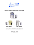
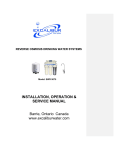
REVERSE OSMOSIS DRINKING WATER SYSTEMS
INSTALLATION, OPERATION & SERVICE MANUAL
220 Bayview Drive, Unit 18
Barrie, ON L4N 4Y8
www.excaliburwater.com
TABLE OF CONTENTS
INTRODUCTION
.
Page
1
PREPARATION
A. Major System Components
Installation Drawing
B. Tools Recommended for Installation
C. Site Selection For Major System Components
2
3
4
4
INSTALLATION STEPS
A. Faucet Installation
Faucet Drawing
B. Feed Water Ball Valve Installation
C. Drain Clamp Installation
D. Position the Drinking Water Holding Tank
and Make the Final Hose Connections
E. Start Up
5
6
7
8
9
9
OPERATION AND MAINTENANCE
A. Normal Operation
B. Changing Filters
C. Changing the In-Line Activated Carbon Post Filter
10
10
11
TECHNICAL DATA
A. Water Quality
11
TROUBLESHOOTING GUIDE
12/13
DRAWINGS Filter change
14
CAUTION:
The Centers for Disease Control and Prevention (CDC) and the Environmental Protection Agency (EPA) have issued guidance to people
with severely weakened immune systems who may want to take extra precautions to reduce the risk of infection with Cryptosporidium from
drinking water. This guidance pertains to people with HIV/AIDS, patients receiving treatment for cancer, recipients of organ or bone marrow
transplants, transplant patients taking immunosuppressive drugs, and persons who have congenital immunodeficiencies.
The EPA has stated that they do not know the importance of drinking water compared to other possible sources of Cryptosporidium to
determine how most people become infected. The CDC-EPA guidance suggest that immunosuppressed individuals discuss their risks with
their health care provider.
All individuals should take adequate precaution when changing the filter cartridges, including wearing protective gloves, to avoid direct
contact with the exhausted cartridges.
*For complete specifications, refer to the Performance Data Sheet.
The membrane is a specially constructed, Fully
aromatic polyamide film, and is classified as a
Thin Film Composite (T.F.C.).
The spiral wound construction of the Reverse
Osmosis Membrane provides maximum surface
area for water production and is less susceptible
to fouling by particulate matter, turbidity and
colloidal materials.
INTRODUCTION
Your new Reverse Osmosis Drinking Water
System uses a combination of filtration
technologies to reduce unwanted contaminants in
your water supply. The following steps combine to
give you the best in clear sparkling drinking water:
MECHANICAL FILTRATION - The Sediment
Pre-filter will remove the larger particles such as
silt, rust and scale. Its 5 micron (equal to 0.0002
inch) nominal rating helps to give maximum life
to the Reverse Osmosis Membrane.
IN-LINE ACTIVATED CARBON COCONUT
SHELL POST FILTER – The In-Line Activated
Carbon Post Filter is located after the Holding
Tank and reduces the tastes and odors that may
pass through the system. It adds a final polish to
the water.
CARBON BLOCK – The Carbon Block Pre-filter
contains carbon with a vast network of pores.
The tremendous surface area of these pores
(typically 800-1200 square meters per gram of
carbon) gives the carbon very good adsorptive
sites for substances that contribute to tastes and
odors. The carbon block in the Pre-filter will
remove any chlorine that may be present in the
feed water. This pretreatment is necessary for
membrane protection.
AUTOMATIC SHUTOFF VALVE – The ASO
Valve senses when the product water tank is full
and closes the feed water supply to prevent
excess reject water from going to drain when the
unit is not producing water.
REVERSE OSMOSIS MEMBRANE – The
Reverse Osmosis Membrane is the heart of the
filtration system. It is designed to reduce the
dissolved mineral content of the water. Minerals
picked up in the environment by the water are
measured as Total Dissolved Solids (TDS). In
the Reverse Osmosis process, dissolved
minerals are separated from the incoming water
(the Permeate). The excess minerals are rinsed
to drain (the Reject Water).
BOOSTER PUMP – The in line booster
pump will increase the incoming water
pressure after the pre sediment and
carbon filtration stages to 80psi for
maximum efficiency and production
quality through the TFC membrane
TDS removal process. Power standard
outlet plug 110V / 60 Hz is required.
IMPORTANT NOTICES:
This Reverse Osmosis system contains replaceable treatment components critical for effective performance. It
is the user's responsibility to, and the manufacturer strongly recommends that the user, periodically test the
product water to verify the system is performing satisfactorily.
This system is acceptable for treatment of influent concentrations of no more that 27 mg/l nitrate and 3 mg/l
nitrate in combination measured as N and is certified for nitrate/nitrite reduction only for water supplies with a
pressure of 40 psig (280 kPa) or greater.
DO NOT USE WITH WATER THAT IS MICROBIOLOGICALLY UNSAFE OR OF UNKNOWN QUALITY,
WITHOUT ADEQUATE DISINFECTION BEFORE OR AFTER THE SYSTEM. Systems certified for cyst
reduction may be used on disinfected water that may contain filterable cysts.
1
PREPARATION
A. Major System Components
The following components comprise the Reverse
Osmosis Drinking Water System. (Refer to Fig. 1,
below for general system layout.)
9. A Sediment Pre-filter, shrink wrapped.
6. A Drain Clamp.
10.An activated Carbon Pre-filter, shrink
wrapped.
11.An In-Line Activated Coconut Shell
Carbon Post Filter.
12.Other items necessary for installation may
include wood screws or machine screws
and nuts for mounting the manifold, or
concrete anchors for hanging on
basement wall. Additional tubing or tube
connectors. Plastic wire ties for
organizing tubing.
7. Plastic Tubing and tube connectors.
13. Installation Kit
1. A Reverse Osmosis Manifold assembly
2. Housings and Housing O-rings.
3. A Drinking Water Holding Tank.
4. A Dispensing Faucet.
5. A Feed Water Ball Valve.
8. A Reverse Osmosis Membrane sealed in a
plastic bag.
BALL
2
BALL
3
C. Site Selection for Major System Components
3
C. Site Selection for Major System Components
B. Tools Recommended for Installation
The Reverse Osmosis System was designed to fit
under a sink, however, because of space limitations
or other reasons, the system's flexible design allows
for other locations. When determining the location
remember that access to a cold water tap line, the
household drain, and ease of filter replacement are
important considerations.
The following tools will cover most of the
installation sites encountered:
1. 3/8" variable speed electric drill.
2. Extension work light with outlet.
3. Safety glasses.
4. 11/4" Greenlee hole punch and 1/8" and
½"metal drill bits for pilot hole.
All components and tubing should be located in an
area not exposed to freezing temperatures. If winter
temperatures are sever, the area should be above
the minimum temperature listed in Table B, page 2
for proper performance. Do not expose unit or
tubing to direct sunlight.
6. Center punch and hammer.
7. 11/4" wood bit.
8. Concrete drill bits.
9. Assorted wood and metal drill bits including
7/32" metal drill bit.
1. Drinking Faucet – The faucet should be placed
near the sink where drinking water is normally
obtained. Convenience of use (filling of water
pitchers and glasses), and an open area
beneath the faucet under the sink for attaching
product and drain tubing are considerations. A
2" diameter flat surface is required above and
below the installation site. The thickness of the
mounting surface should not exceed 1 ¼".
Watch for strengthening webbing on the
underside of cast iron sinks.
10. Phillips head and flat blade screwdrivers.
11. ½", 9/16" and 5/8" open end wrenches.
12. 10" Crescent wrench with jaws taped to
hold faucet.
13. Basin wrench or 10" pipe wrench.
14. Teflon tape.
15. Wide masking tape or duct tape.
16. Plastic tubing cutter.
17. Extra plastic tubing.
2. Drinking Water Holding Tank – The Holding
Tank may be placed where it is convenient
within 10 feet of the faucet; under the sink, in an
adjacent cabinet are the best choices or in a
basement within 20 feet of the faucet. If a longer
run of tubing is required, the tubing should be
the 3/8" diameter OD size to prevent a high
pressure drop. Remember, these tanks can
weigh up to 30 pounds when full of water; a firm,
level area is required.
18. Low range air pressure gauge.
19. Small bottle of liquid chlorine bleach.
20. Paper towels, wisk broom and assorted
clean up materials.
3. Reverse Osmosis Manifold Assembly – The
manifold can be installed on either the right or
left side of the under-sink area or a cabinet. The
right side is recommended because all the
tubing will be to the back of the cabinet and out
of the way. Installation in the basement is also
an option; one location is near the laundry/utility
sink where cold potable water and rain access
are handy. The mounting location should allow
adequate clearance and accessibility for
cartridge changes.
4
2b. Drilling a porcelain sink:
4. Feed Water Connection – The Feed
Water Ball Valve should be located as
close to the manifold assembly as
possible. USE A POTABLE COLD WATER
SUPPLY ONLY. Softened water is
preferred as it will extend the life of the
Reverse Osmosis Membrane.
It is best to use a special 1¼" diameter cutter
designed for porcelain. A carbide tipped
masonry bit is a second choice.
• Place a piece of tape over the area to be
drilled to help prevent chipping.
• Drill a pilot hole for the porcelain cutter. Use
the pilot drill supplied with the kit or a carbide
tipped drill.
• When drilling the 1¼" hole, drill slowly and
carefully; the porcelain chips easily.
• After drilling, clean the area well. Iron fillings,
if left in place, can cause rust stains.
5. Drain Connection – The waste water must
go to a drain connection with easy access.
Do NOT connect the system drain line to
the dishwasher drain or near the garbage
disposal.
INSTALLATION STEPS
All plumbing should be done in accordance
with state and local plumbing codes.
2c. Drilling a counter top:
NOTE: The counter top must be less than 1¼"
thick. Treat ceramic tiles as porcelain until the
tile is penetrated, then use the carbide tipped
metal cutter.
In restricted under-sink areas, it may be easier
to install the faucet first. Allow adequate
tubing lengths for any final component
position.
Formica counter tops may be drilled with a good
1 ¼" wood bit, drilling a 3/32" pilot hole will help
keep the bit going straight.
A. Faucet Installation
2a. Drilling a stainless steel sink:
• Center punch the hole to provide a
starting point for the drill.
• Start with a smaller drill as a pilot, and
then drill a ½" diameter hole to accept
the bolt of a 1¼ " Greenlee Hole Punch
(1¼" chassis punch).
• Clean away any chips.
• Install the punch and tighten the nut to
cut the hole.
• Deburr any sharp edges.
5
LONG REACH FAUCET
Figure 2A
6
B. Feed Water Ball Valve Installation
3. With the Feed Water Ball Valve closed,
open the sink faucet and the water supply
and allow the water to run for a few minutes
to flush any debris caused by the
installation.
Decide on location. Do NOT connect to a hot
water feed line. If you are not sure of the
supply, run the hot water and feel the supply
piping. Water over 100ºF may cause
permanent damage to the Reverse Osmosis
Membrane. (Refer to Fig. 3 page 8.)
1. Shut off the water supply and drain the line.
2. To install the Feed Water Ball Valve:
•
You will require 1 – ½" MIP fitting
(threaded on one end).
•
To begin, unscrew the copper pipe and
fitting which is located directly under the
sink.
•
Place some Teflon Tape on the threads
of the copper pipe as well as the threads
on the feed water ball valve.
•
Screw the copper pipe into the feed
water ball valve.
•
Screw the pipe with the FIP fitting onto
the opposite end of feed water ball valve.
•
Remove nut from the feed water ball
valve.
•
Slide the nut onto the ¼” reverse
osmosis tubing.
•
Place the ¼” tubing onto the exposed
threads of the feed water ball valve.
•
Screw the nut onto the feed water ball
valve.
•
Close the faucet and check the Feed
Water Ball Valve for leaks.
•
Once installation of Reverse Osmosis
unit is completed open feed water ball
valve to allow flow of water.
FEED WATER BALL VALVE
¼” R.O. tubing
nut
pipe
FIP
Teflon Tape
Ball Valve
Copper pipe with
threads
Figure 3
7
3. Locate the 3/8" Black Drain Tubing
connected to the Reverse Osmosis Unit.
Route to the tubing to the Drain Clamp and
trim to length.
C. Drain Clamp Installation
Choose the drain outlet location.
The following are instructions for discharging
in the sink drain pipe. (Refer to Fig. 1, page 3)
NOTE: When cutting the polytubing make
clean, square cuts, failing to do so could
result in poor connections and possible
leaks.
1. Position the Drain Clamp on the sink drain
pipe above the drain trap. Allow room for
drilling. Tighten securely.
CAUTION: The lowest point of the line
should be the point of connection to the
Drain Clamp. There should be no sag in the
line as this may cause excessive noise as
the reject water is flowing to drain.
2. Use a battery powered or properly
grounded drill. Using the Clamp port as a
drill guide, drill a 7/32" hole through the
wall of the drain pipe. Do NOT penetrate
the opposite side of the pipe.
• Refer to Fig. 4, below. To connect the
Drain Tubing, install the Compression Nut
and the Brass Insert.
• Insert the tubing into the Drain Clamp and
tighten the Compression Nut.
Figure 4
8
• Slowly open the Feed Water Ball Valve
(turning counter clockwise).
D. Position the Drinking Water Holding Tank
and Make the Final Hose Connections
• As soon as the water begins to come out of
the Dispensing Faucet, close the Faucet.
1. Check the tank pre-charge pressure. Make
sure it is between 5 to 7 psig. If not, use a
bicycle hand pump or other pump to bring
the pressure up to the 5 to 7 psig range.
• Let stand for 15 minutes.
NOTE: During this time, check the system
carefully for leaks.
2. Pull the cap/plug off the top of the tank
where the Tank Shut-Off should go. (Refer
to Fig. 1, page 2)
• At the end of 15 minutes, CLOSE the Feed
Water Ball Valve and open the Dispensing
Faucet.
3. Wrap Teflon tape three times around the
¼" male outlet thread. Wrap in the direction
of the threads (clockwise when looking
down on the Holding Tank). The tape will
act as a thread sealant. Screw on the
Holding Tank Shut-Off Valve.
• Allow the Holding Tank to completely drain.
Then remove the Activated Carbon Pre-filter
Housing, empty, and install the activated
Carbon Pre-filter. Firmly tighten the Housing
hand tight only.
4. Locate the 3/8" Tubing. Firmly press one
end into the Holding Tank Shut-Off Valve
and the other end into the tee. (Refer to
Fig. 1, page 2.) The fittings will grab the
tubing and seal it in place. Make sure the
tubing is pressed all the way in to create a
pressure tight connection.
2. Installing the Reverse Osmosis
Membrane:
• Remove the Reverse Osmosis Membrane
Housing, (the closest of the three to In/Out
ports), and empty.
• Insert the Membrane into the Membrane
Housing. (The O-rings should be up toward
the Membrane Housing cap.) Check the
Housing O-ring for proper position in its
groove, engage and firmly tighten the
Housing hand tight only.
E. Start Up
At time of start up and each time the filters
are changed the system should be sanitized.
1. Sanitizing the system and installing the
Sediment Pre-filter. Use a drip pan to aid
clean-up.
3. Rinsing the system:
• Slowly open the Feed Water Ball Valve fully
counter clockwise.
NOTE: The system should be sanitized
BEFORE installing the Activated Carbon Prefilter and the Reverse Osmosis Membrane.
• The Holding Tank Valve should be open.
The Reverse Osmosis System is now
making water.
• Use a good quality unscented liquid
chlorine household bleach.
• Open the Dispensing Faucet by lifting the
black handle and open the Holding Tank
Shut-Off Valve (the handle should be
parallel with the valve body).
• Remove the Housing on the side of the
manifold labeled "SEDIMENT". Pour one
capful of bleach (this is approximately 2
tsp. or 10 ml) into one of the white
Housings. Unwrap Sediment Pre-filter and
install pre-filter (press firmly into place).
Engage and firmly tighten the Housing
hand tight only.
• Remove all Housings add one capful of
bleach in each. Engage and firmly tighten
the Housings hand tight only.
• Do not use the first three full tanks of water.
CAUTION: The Reverse Osmosis
Membrane is shipped with a preservative in
it (0.5% sodium metabisulfite). This will be
rinsed out with the first water produced.
Allow the Holding Tank to fill (overnight) and
discard the first three full tanks of production.
When the Faucet is first opened, expect air
and carbon fines (very fine black powder)
from the In-Line Activated Carbon Post Filter
to be rinsed out. This is normal for the first
tank of water or after the In-line filter is
changed.
9
Use a drip pan to catch any water that may spill
when the Filter Housings are removed. Refer to
Fig. 1, page 3 for component location.
OPERATION & MAINTENANCE
A. Normal Operation
1. Reverse Osmosis systems produce
drinking water at relatively slow rates, it can
take up to 3 hours to fill the Holding Tank.
Normal operation is to let the Holding Tank
fill with water and then draw water as is
needed. When the pressure in the Holding
Tank falls to a given pressure (as the water
is being used) the Automatic Shut-Off
Valve (ASO Valve) will start water
production and the system will refill the
Holding Tank. When the Holding Tank is
full and no water is being used, the ASO
Valve will automatically shut off the feed
water to conserve water. The more water
that is used (up to the capacity of the
system) the better the Reverse Osmosis
system will function. Other uses for the
water are flowers, pets and rinsing
glassware.
1. Close the Feed Water Ball Valve by turning
fully clockwise and open the Dispensing
Faucet by lifting the handle. Allow the
Holding Tank to empty.
2. Loosen and remove the Sediment Pre-filter
and the Activated Carbon Pre-filter
Housings. Discard the filters.
3. Wash the inside of the Housings using a mild
detergent and a soft cloth. Do not use
abrasive cleaners or pads. Thoroughly rinse
all soap from the Housings before
reassembly.
4. To sanitize the system and replace the
filters:
NOTE: The system should be sanitized
before installing the Activated Carbon Prefilter.
• Use a good quality unscented liquid
chlorine household bleach.
With each use it is recommended that you
run the tap for at least 10 seconds prior to
using water. This is especially important if
the water tap has not been used daily.
After periods of non-use, such as a week
of vacation, it is better to empty the Holding
Tank and allow the system to produce
fresh water for use. If the system is not
used for 3-4 weeks or longer, it is a good
idea to re-sanitize the system and to
change the pre-filter and post filters.
• Add one capful of bleach (this is 2 tsp. or
10 ml) to the Sediment Pre-filter Housing
and install the Sediment Pre-filter. Check
the Housing O-ring for proper position in its
groove, engage and firmly tighten the
Housing hand tight only.
• Add one capful of bleach to the Activated
Carbon Pre-filter Housing. Install the
Housing without the Activated Carbon Prefilter.
B. Changing Filters
THIS REVERSE OSMOSIS SYSTEM
CONTAINS FILTERS WHICH MUST BE
REPLACED AT REGULAR INTERVALS TO
MAINTAIN PROPER PERFORMANCE. USE
ONLY FACTORY APPROVED FILTERS.
• The Dispensing Faucet should be open,
slowly open the Feed Water Ball Valve.
• As soon as the water begins to drip out of
the Dispensing Faucet, close the Faucet.
• Let the system stand for 15 minutes.
All individuals should take adequate
precautions when changing the filters,
including wearing protective gloves, to
avoid direct contact with the exhausted
filters.
• At the end of 15 minutes, in the following
order, close the Feed Water Ball Valve,
close the Holding Tank Valve and open the
Dispensing Faucet to release the pressure.
• Remove the Activated Carbon Pre-filter
Housing and empty. Remove the wrapping
and install the Activated Carbon Pre-filter.
Firmly tighten the Housing hand tight only.
The recommended interval for changing the
filters (not the Reverse Osmosis Membrane)
is every six (6) months. Typical T.F.C.
Membrane life expectancy is Five to ten
years with Water Softener prior to Reverse
Osmosis system. Local conditions may
dictate more frequent changes.
• Disconnect the tubing that runs from the
Holding Tank to the Tee (see Fig. 1, page
3). Put 50 drops of bleach (this is ½ tsp. or
10
3 ml) into the tubing and reconnect it to the
Tee.
5. Slowly open the Feed Water Ball Valve.
6. When water begins dripping out of the
Faucet, in the following order, close the
Faucet and open the Holding Tank
Valve. When the Faucet is first opened,
expect air and carbon fines (very fine
black powder), from the new Post Filter
to be rinsed out. This is normal for the
first tank of water.
NOTE: Now is the convenient time to
change the In-Line Activated Carbon Post
Filter.
• Slowly open the Feed Water Ball Valve.
When water begins dripping out of the
Dispensing Faucet, in the following order,
close the Faucet and then open the Holding
Tank Valve.
• Do not open the Faucet for at least 5 hours.
• Discard the first three full tanks of water
produced, they will contain chlorine.
TECHNICAL DATA
C. Changing the In-Line Activated Carbon
Post Filter
A. Water Quality
1. Close the Feed Water Ball Valve by turning
fully clockwise.
Water quality is normally measured with a
special meter that measures the water's
ability to conduct electricity. The more
dissolved solids in the water, the higher the
conductivity. The results are usually
reported in Parts per Million (ppm) or
Milligrams per Liter (mg/l) of Total
Dissolved Solids (TDS). (Although
technically they are not exactly equal, in
most discussions ppm = mg/l).
2. Close the Holding Tank Valve and then
open the Dispensing Faucet to release the
pressure.
3. Remove the In-Line Activated Carbon Post
Filter. Disconnect the used Post Filter by
pressing in the connector's collar and at the
same time pulling the tube out of the fitting.
Unscrew the fittings on the In-Line, reTeflon tape them and install them on the
new Post Filter. Do not over tighten the
fittings.
4. Firmly reconnect the polytubes to the new
Post Filter. (Refer to Fig. 5 below.)
IN-LINE COCONUT SHELL CARBON
POST FILTER ASSEMBLY
Reverse Osmosis Membranes are rated by
the amount of dissolved solids that are
rejected. This rating is a ration of the TDS in
the feed water to the TDS in the product
water and is reported as Percent
Rejection. If the feed water contained 100
ppm of TDS and the product water
contained 10 ppm of TDS, 90 ppm have
been rejected and the reject ration is 90%.
Percent Rejection =
Feed TDS – Product TDS
Feed TDS
OUT
EXAMPLE: Feed water is 500 ppm TDS
and the product water is 75 ppm TDS.
IN
From
tank
To Faucet
In-line Coconut Shell
Carbon Post Filter
Percent Rejection = 500 – 75 x 100%
500
Percent Rejection = 0.85 x 100% or 85%
Figure 5
11
TROUBLE SHOOTING GUIDE
Problem
Low quantity of Product Water
from Holding Tank
Possible Cause
Feed Water Ball Valve is plugged
or closed.
Clogged Sediment Pre-filter or
Activated Carbon Pre-filter.
Low water pressure.
Reverse Osmosis. Membrane is
fouled.
Plugged In-Line Activated Carbon
Post Filter.
Air pre-charge pressure in Holding
Tank is too high.
Air pre-charge is too low
Low pressure at the Dispensing
Faucet
Air Bladder in the Holding Tank is
ruptured.
Holding Tank Valve is closed.
No drain flow, the Drain Restrictor
is plugged.
The Check Valve is stuck.
The ASO Valve is malfunctioning.
In-Line Activated Carbon Post Filter
is plugged.
Air pre-charge in the Holding Tank
is too low.
Holding Tank Valve is partially
closed.
The dispensing Faucet is out of
adjustment or faulty.
Heavy water use, Holding Tank is
depleted.
Low Water Production.
High Total Dissolved Solids
(TDS) in the Product Water
Clogged Sediment Pre-filter or
Activated Carbon Pre-filter.
Low Water Pressure.
Reverse Osmosis Membrane Oring is crimped.
Reverse Osmosis Membrane brine
seal is not sealing up into the
manifold head.
Reverse Osmosis Membrane is
expended.
12
Solution
Open Valve or unclog.
Replace filters.
Feed Water pressure must be
above 40 psig.
See Feed Water operating limits.
Correct cause of fouling, replace
Membrane.
Replace Post Filter.
Empty water from Holding Tank,
and with the faucet open, adjust air
pressure to 5 – 7 psig (35–48 kPa)
range.
Replace tank.
Open Valve.
Clear or replace Drain Restrictor.
Free check.
Replace ASO Valve components.
Replace Post Filter.
Empty water from Holding Tank
and with the faucet open, adjust air
pressure to 5 – 7 psig (35-48 kPa)
range.
Check for leakage at the Air Valve
Stem.
Open Valve
Repair or replace Dispensing
Faucet.
Allow Holding Tank to refill (adding
a second Holding Tank will
increase storage capacity).
See Low Quantity of Product Water
from Holding Tank section above.
Replace Filters.
Feed Water Pressure must be
above 40 psig.
Check Feed Water Ball Valve.
Check O-ring.
Check the brine seal.
If Membrane life is unusually short,
find and correct the problem.
Replace Membrane.
Problem
High Total Dissolved Solids
(TDS) in the Product Water
(continued)
Possible Cause
The Product Water and Drain
Water lines are reversed.
No drain flow, Drain Restrictor is
clogged.
The ASO Valve is not closing.
New In-Line or Activated Carbon
Pre-filter not rinsed completely.
The Feed Water TDS has
increased.
Tastes and odors in the Product
Water
Drain Water overflows at the Air
Gap Faucet
Faucet leaks or drips
The In-Line or Activated Carbon
Pre-filter is exhausted.
There is foreign matter in the
Holding Tank.
The Product Water and Drain
Water lines are reversed.
Dissolved gassed in the Feed
Water.
Increase in Product Water TDS.
Drain tubing is clogged.
Drain clamp hole is misaligned.
Excessive drain flow rate.
Leaks from spout.
Leaks from base of the delivery
tube.
Leaks from beneath the handle.
Fitting leaks in general
Solution
Correct plumbing.
Clear or replace Drain Restrictor.
Repair or replace the ASO Valve
Components.
Flush with several full tanks of
Product Water.
An increase in Feed Water TDS will
give a corresponding increase in
Product Water TDS.
Replace Filters.
Clean, flush and sanitize the
system. Replace the filters.
Correct plumbing.
Pre-treat Feed Water to remove
dissolved gasses.
See high TDS in the Product Water
section.
Clear tubing.
Align with hole in the drain pipe.
Replace Drain Restrictor.
Adjust Faucet by turning the tee
bar just below the handle to provide
a small amount of free play in
handle when shut off.
O-rings are bad, repair or replace
faucet.
O-ring is bad, replace O-ring.
O-rings are bad. Repair or replace
the faucet.
Close the Feed Water Ball Valve and relieve pressure before
disconnecting any tubing or replacing any fitting. Before replacing a fitting,
re-cut the tubing and re-insert into the fitting to see if that solves the leak.
If pipe threads are leaking, remove and re-tape with Teflon tape.
13
14