1
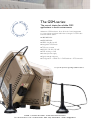
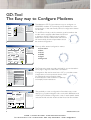
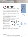
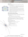
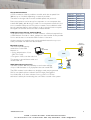
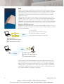
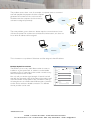
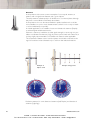
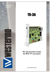
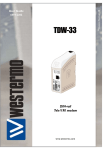
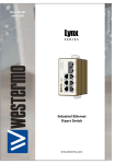
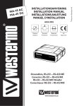
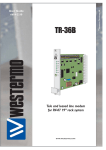
Reliable Data Communication
via GSM Networks
AUDIN - 8, avenue de la malle - 51370 Saint Brice Courcelles
Tel : 03.26.04.20.21 - Fax : 03.26.04.28.20 - Web : http: www.audin.fr - Email : [email protected]
Save Time and Money with Secured
Wireless Connections Worldwide
Produced by:
Westermo Teleindustri AB
Photo:
IStockphoto
BildN, Västerås, Sweden
Illustrations:
Visual Information Sweden AB
Eskilstuna, Sweden
Printed by:
Eskilstuna Offset AB
Sweden 2007
Specifications are subject to
change without notice due to
continuous product development and improvement.
The ability to create remote connections to equipment can provide companies
great savings both in time and money. Not only this, but improved customer
service can also be offered. It is possible to control, monitor, update software or
fault find, irrespective of where the equipment is located, by means of a simple
remote connection.
Being able to connect to a remote server whilst working from home or using a
laptop PC when travelling makes for much more efficient and flexible working
conditions for many support engineers.
Why use industrial products?
Westermo designs and develops products for use in industrial applications and
environments with high interference levels. With over 30 years of experience
we are fully conversant with the market’s need for reliability and functionality,
where a product is expected to work faultlessly for many years.
These are some of the factors that we consider when we develop a new
product to provide an optimal final cost.
AUDIN - 8, avenue de la malle - 51370 Saint Brice Courcelles
Tel : 03.26.04.20.21 - Fax : 03.26.04.28.20 - Web : http: www.audin.fr - Email : [email protected]
The GSM-series:
The natural choice for reliable GSM
applications in harsh environments
Westermo GSM-modems allow all kinds of serial equipment
to communicate anywhere within the coverage of a GSM radio
base transceiver station.
… 900/1800 MHz
… 850/1900 MHz
… GPRS, class B, class 10
… Integrated TCP/IP stack
… TCP auto connect
… RS-232 / RS-422 / RS-485
… DTR -dialling or SMS
… Isolated power supply
… Signal strength indicator
… Configuration: • GDW-Tool • DIP-Switches • AT-Commands
See specific product regarding available features.
AUDIN - 8, avenue de la malle - 51370 Saint Brice Courcelles
Tel : 03.26.04.20.21 - Fax : 03.26.04.28.20 - Web : http: www.audin.fr - Email : [email protected]
GD-Tool
The Easy way to Configure Modems
GD-Tool
File
Connection
Connection
Tool
Basic
Help
Serial
SMS
GPRS
Signal
Diagnostic
Connection Settings
COM Port
Search for a supported Westermo
modem on the selected COM port.
This make take several minutes.
Aut
Autoconnect
1
Baud rate
115200
Connects to a supported Westermo
modem, using current settings.
Reconnect
Parity
None
Connected
1
115200
8
None
1
GDW-11
Ok
Connection
Status:
Port:
Baud rate:
Data bits:
Paity:
Stop bits:
Modem:
SIM card:
Connected
1
115200
8
None
1
GDW-11
Ok
Closes the COM port, and disconnects
any connected modem.
Disconnect
Data bits
Opens the COM port with current
settings for the terminal window.
8
Open
Stop bits
Connection
Status:
Port:
Baud rate:
Data bits:
Paity:
Stop bits:
Modem:
SIM card:
1
Connected...
GD-Tool
File
Connection
Tool
Help
Basic
Connection
Serial
SMS
GPRS
Signal
Diagnostic
Security [+CPIN],[+CLCK] & [+CPWD]
Enter PIN
Factory Settings [&F]
Change PIN
Call
Enable PIN
Factory
Auto PIN [”WPIN]
Rings to auto-answer [S0]
OpenAT
PIN
000
Disable
Enabled
Reset [+WRST]
Enabled
Delay [hhh:mm]
Time to reset [hhh:mm]
[+CFUN=1]
Reset Now
Data
Bearer type - speed [+CBST]
Bearer type - ce [+CBST]
0 - Autobauding
1 - Non transparant only
Compression [%C]
Error Connection Mode [\n]
0 - No compression
Status led [”WSTATLED]
0 - No error correction
0 - No error correction
Set DTR Toogle Event [%D]
Select DTR Event
The Westermo GD-Tool provides two ways to configure our
GSM/GPRS modems. AT commands can be entered into a terminal window or the user friendly GD-tool configuration screens
can be used.
To use GD-tool firstly a serial connection must be made to the
modem with a standard cable. Next the GD-tool
is started on the PC. Options are provided to
either Auto-connect or Reconnect and the tool
will automatically download parameters about
the current configuration.
The tool offers several configuration menus:
……Connection
……Basic
……Serial
……GPRS
……Signal
……Diagnostic
Read
Activate
Deactivate
Write
Test
Connected...
GD-Tool
File
Connection
Tool
Basic
Connection
Help
Serial
SMS
GPRS
Information
Revision identification [ATI3]
Diagnostic
Signal
657c09gg.Q2406B 1956992 042407 11:29
Westermo Software revision [ATI9] SW version: 4100-9403, Jul 13 2007, 13:46:54
IMEI [+CGSN]
357832000022553
Network Registration [+CREG]
0,2
GPRS Network Reg. [+CGREG]
0,0
GPRS status [”WIPSTATUS]
IP stack state: DISCONNECTED
Current local IP: none
Modem Configuration [AT&V]
Q:0 V:1 S0:000 S2:043 S3:013 S4:010 S5:008
+CR:0 +CRC:1 +CMEE:1 +CBST:0,0,1
+SPEAKER:0 +ECHO:0,1 &C:1 &D:2 %C:0
+IPR:115200 +ICF:3,4 +IFC:2,2
GPRS Configuration [”WTCPV]
“WGPRSAPN: ”static. voafone.net”
“WGPRSUN: ””
“WGPRSPW: ””
Connection
Status:
Port:
Baud rate:
Data bits:
Paity:
Stop bits:
Modem:
SIM card:
Connected
1
115200
8
None
1
GDW-11
Ok
Connection
Status:
Port:
Baud rate:
Data bits:
Paity:
Stop bits:
Modem:
SIM card:
Connected
1
115200
8
None
1
GDW-11
Ok
The Diagnostics screen provides vital help for any service technician trying to diagnose a fault with a connection.
Configuration files can be saved onto a PC so once the correct
configuration is found a particular brand of PLC
for instance this can be saved and then
downloaded into other modems to speed up
and simplify future installations.
“WTCPSERV: ”255.255.255”
“WTCPCLIENTIP: ”0.0”
“WTCPPORT:
13618
”WTCPTXDELAY: 11829
“WTCPMODE: 0
”WTCPPINGSYNC: 20,0,0
Create Report
Reload
“WTCPCONNECT: 0
Connected...
GD-Tool
File
Connection
Tool
Help
New Profile
GPRS
SMS
Open Profile
Signal
Diagnostic
Save Profile
Close Profile
PRSAPN]
Auto connect [”WTCPCONNECT]
0 - Disabled
Write Profile to modem
Exit
Connection mode [”WTCPMODE]
0 - Client
Alt+F4
Password [”WGPRSPW]
Delay [”WTCPTXDELAY]
11829
IP Server [”WTCPSERV]
255 . 255 . 0 . 255
13618
TCP connect status information [”WTCPI]
0 - No status information
Autoconnect sync [”WTCPPINGSYNC]
Mode
Delay
Idle
On
0
Connect
Client IP [”WTCPCLIENTIP]
0
GPRS
The possibility to save a configuration file makes it very convenient for e.g. a system integrator who works with different brands
of PLC’s. Just make the configuration ones for each specific device
and save the file and then download the file to the next modem.
0 . 0 . 0 . 0
TCP
Ping
Start
Stop
GPRS attach/detach [+CGATT]
State
1 - Attached
Change
Read
Write
Connected...
4
www.westermo.com
AUDIN - 8, avenue de la malle - 51370 Saint Brice Courcelles
Tel : 03.26.04.20.21 - Fax : 03.26.04.28.20 - Web : http: www.audin.fr - Email : [email protected]
GSM
(Global System for Mobile communication)
Connection time between GSM modems is 4 – 8 seconds
(using the V.110 protocol).
GSM makes the wireless transfer of voice/text/images between different
types of equipment possible, but only within the coverage area of a network
operator's base transceiver station. It is possible to use GDW-11 / GD-01 on
different operators networks and between different countries (Roaming).
The number of users of GSM equipment has, after standardisation, increased
rapidly, primarily with voice services, but a major increase is now also occurring
within industrial applications, in particular M2M communication, (Machine to
Machine).
This can be to transfer data or alarms from a number of slave units to a master
system or the transfer of data from or between parking meters and other
similar equipment. The application and possibilities are endless.
Architecture of a GSM Network
ME (Mobile Equipment): Each ME unit has a unique identification IMEI-number, (International Mobile Equipment Identy). This makes it possible for the network operator
to block the use of a unit, e.g. when a ME unit has been stolen.
SIM (Subscriber Identity Module): The
SIM-card is furnished by the network
operator and holds data such as:
telephone number, PIN code, address
book etc.
BTS (Base Transceiver Station): Is a
base radio station, i.e. a transmitter
and receiver that makes it possible to
communicate with some form of ME.
MS
MS
BTS
BTS
PSTN
ISDN
...
MSC
BSC
MS
BCS (Base Station Controller): Is a
substation that communicates with
the base radio station. The substation
can communicate with a number of base stations.
BTS
BSC
MSC (Mobile Switching Centre): Makes forwarding to an analogue, PSTN (Public
Switched Telephone Network) or an ISDN (Integrated Services Digital Network) digital
network possible.
www.westermo.com
AUDIN - 8, avenue de la malle - 51370 Saint Brice Courcelles
Tel : 03.26.04.20.21 - Fax : 03.26.04.28.20 - Web : http: www.audin.fr - Email : [email protected]
5
Cell structures
E21
A1
D2
A1
C9
C19
C18
E21
B3
A1
C17
C16
C12
B5
C13
C15
E21
C11
B4
B6
D2
C10
B2
B7
A1
E21
C8
C14
A1
Base stations are positioned to give maximal coverage. The area covered by a
base station is called a cell.
The entire GSM network is organised with cells of varying sizes. A cell
can cover areas with a radius of 200 metre (656 ft) up to areas with a
radius of ~30 km (18.64 mi). This depends on where the base station is
D2
located and the surrounding environment.
A1
Other factors that affect the installation are, among others, the output
power and whether the base station is located in an environment that
E21
is problematic for radio traffic. The cell structure results in the reuse of
frequencies in the base stations. In the figure on the left shows that the
D2
frequency A1 can be reused in the third ring without the risk of crosstalk
between cells with the same frequency.
If you travel through an area it is necessary to switch between the cells through
which you pass. This is known as handover.
Radio transmissions between MS and BSS
In the eighties when the GSM specification was drawn up, the ITU (International
Telecommunication Union) reserved two frequency bands of 25 MHz for GSM
radio transmissions:
… 880–915 MHz “uplink” transfers from MS to BSS.
… 925–960 MHz “downlink” transfers from BSS to MS.
The development within mobile communication has resulted in the need to use
multiple frequencies to satisfy demand. Today there are five standardised
frequencies 400, 850, 900, 1800 as well as 1900 MHz. The latter frequency is
generally used in the USA and in some parts of Asia, while 900 and 1800 are
more globally used.
Services on the GSM network
There are a number of services available via GSM such as:
… Telephony.
… CSD (Circuit Switched Data, data transfer).
… SMS (Short Message Service).
… MMS (Multimedia Message Service).
… FAX.
… GPRS (General Packet Radio Service).
6
www.westermo.com
AUDIN - 8, avenue de la malle - 51370 Saint Brice Courcelles
Tel : 03.26.04.20.21 - Fax : 03.26.04.28.20 - Web : http: www.audin.fr - Email : [email protected]
Circuit Switched Data
A CSD connection makes it possible to transfer serial data at speeds from
300 bit/s up to 14.4 kbit/s depending on network providers.
The table on the right side shows the available speeds and protocols.
Data communication can be set up for transparent or non-transparent data
transfer. RLP (Radio Link Protocol) is used in non-transparent transfer; this is an
error corrected GSM protocol. This protocol creates a more reliable transfer,
but also generates delays in the transfer. In order to use this function requires
the support of both the service and the connected devices.
Speed
2400 bit/s
4800 bit/s
9600 bit/s
14400 bit/s
2400 bit/s
4800 bit/s
9600 bit/s
14400 bit/s
Protocol
V.22 bis
V.32
V.32
V.32 bis
V.110
V.110
V.110
V.110
CSD Connection (Circuit Switched Data)
To be able to make a connection to GSM modem is a SIM-card required from
a GSM Network Provider to obtain a telephone / data number. It’s the possible
from a remote site to connect the GSM-modem or vice versa.
As the connection is made through a circuit switched network are you constantly connected until the line is disconnected.
Telephone
004614112233
Network security
The most imported security
mechanisms on the GSM
Network is:
• Strong authentication of user
(SIM / Pin Code).
• Encryption of data over the radio link.
This ensures a secured data transfer and
unauthorised use.
SMS (Short Message Service)
ATD
004614112233
GSM
PSTN
MSC
The GSM modems offer the possibility to send a text message
BSC
of up to 160 characters to any equipment that can handle SMS.
The GSM modems has the feature to be able to send pre-programmed
SMS to one specific phone number if the DTR input are triggered.
It could be used as an alarm indicator from e.g. a PLC to a service
technician’s cellular phone indicating that some faults occured in the system.
BST
www.westermo.com
AUDIN - 8, avenue de la malle - 51370 Saint Brice Courcelles
Tel : 03.26.04.20.21 - Fax : 03.26.04.28.20 - Web : http: www.audin.fr - Email : [email protected]
7
GPRS
GPRS is an extension of GSM network where packet switching data traffic is
supported. With GPRS each channel that is not busy with call traffic is available
for packet switching data traffic. Packets from several different users can be
mixed within the same channel, which results in efficient sharing of available
network resources.
GPRS permits even higher transfer rates as it uses several time slots for the
transfer. In theory rates of up to 115.2 kbit/s can be achieved, however, transfer
rates of between 20 – 50 kbit/s are more common. Transfer rate is however
dependent on several factors and some of them are: operator, terminal, number
of users on the same cell, distance to the base radio station (re-transmissions).
Establish a GPRS Connection
Communication with GPRS uses another procedure. GPRS is based on IP communication and the connected unit must provide an IP address before a connection can be established.
This is done by:
… Connecting to the GPRS network.
… A dynamic address is assigned.
… The exchange of data can take place.
1
2
GPRS
3
1 GPRS attached
2 Dynamic IP addresses alloted
3 Transmitted/Received data
1
GPRS
ISP
Internet
2
3
1 GPRS attached
2 Dynamic IP addresses alloted
3 Transmitted/Received data
Not all operators can offer subscriptions with static address allocation. With
dynamic allocation, you do know from instance to instance which address has
been assigned to the opposing equipment. This is not a problem if the GPRS
modem initiate a connection to the master. The modem will get a dynamic IPaddress after a GPRS attached and can then connect to some equipment that
has a fixed IP-address, for example, a computer.
8
www.westermo.com
AUDIN - 8, avenue de la malle - 51370 Saint Brice Courcelles
Tel : 03.26.04.20.21 - Fax : 03.26.04.28.20 - Web : http: www.audin.fr - Email : [email protected]
The problem occurs when a unit, for example, a computer wants to communicate with peripheral equipment and the computer
generates the connections. No one knows the
IP-address that the computer should connect to,
GPRS
as these are assigned dynamically.
The same problem occurs when two devices need to communicate and none
of them are master. The modem cannot initiate IP-communication, as it does not
know which IP-address will be assigned.
?
GPRS
ISP
Internet
This is however not a problem if all devices could be assigned a fixed IP-address.
Reliable Radio Transmission
The GDW-Tool has a very useful feature when it comes to
installation of the system with an antenna to make reliable
connections. This is a test that can be carried out without any
SIM-card fitted into the modem.
Not only will you see the signal strength of several local cell
sites, but also the actual name of the network provider as well
as the ID-number of that specific radio connection. If the signal strengths are not sufficient then different types of antenna
can be used to achieve a reliable connection or a different
service provider can be used.
GD-Tool
File
Connection
Tool
Connection Basic
Help
Serial
SMS
GPRS
Signal
Diagnostic
Main cell
S COMVIQ
Cell ID: d76c
BER: 5 [3,2%<BER<6,4%]
RxLev: 30
Neighbour 1
S COMVIQ
Cell ID: 680a
RxLev: 22
Cell ID: 57ac
RxLev: 12
Cell ID: fddb
RxLev: 11
Cell ID: a74a
RxLev: 10
Cell ID: d69b
RxLev: 10
Neighbour 2
S COMVIQ
Connection
Status:
Port:
Baud rate:
Data bits:
Paity:
Stop bits:
Modem:
SIM card:
Connected
1
115200
8
None
1
GDW-11
Ok
Neighbour 3
S COMVIQ
Neighbour 4
S COMVIQ
Neighbour 5
S COMVIQ
Neighbour 6
S COMVIQ
Cell ID: d76a
Settings
If RxLev< 16
RED signal indicator
If RxLev> 28
GREEN signal indicator
RxLev: 18
Update interval: 1 seconds
Connected...
www.westermo.com
AUDIN - 8, avenue de la malle - 51370 Saint Brice Courcelles
Tel : 03.26.04.20.21 - Fax : 03.26.04.28.20 - Web : http: www.audin.fr - Email : [email protected]
9
Antennas
A whip antenna is the most common example of a monopole antenna, an
antenna with a single driven element and a ground plane.
The whip antenna radiate equally in all directions in a horizontal plane, although
they have a conical blind zone directly above them.
A whip antenna is not to be recommended in public installations. It could be
more suitable to mount a more discreet antenna, which is not so easy to break
or to be vandalised (Low profile).
In mobile applications is it suitable to have omni directional antennas (Dipole)
to achieve higher reliable transmission.
If there is a stationary installation and the signal strength is not enough is it possible to use directional antennas (Yagi). In point-to-point, fixed radio networks, it
is always highly recommended to use directional antennas when applicable.
This is because of better control over the system and closed construction; the
signal is forced and noise collected only to and from the relevant directions.
Example of Yagi aerial
Example of
Dipole aerial
0
–3
–6
–9
–12
–15
–18
–21
–24
–27
–30
0
–3
–6
–9
–12
–15
–18
–21
–24
–27
–30
Radiation patterns for omni directional antennas (left; Dipole) and directional
antennas (right; Yagi).
10
www.westermo.com
AUDIN - 8, avenue de la malle - 51370 Saint Brice Courcelles
Tel : 03.26.04.20.21 - Fax : 03.26.04.28.20 - Web : http: www.audin.fr - Email : [email protected]
GSM modem
GSM modem for US market
AUDIN - 8, avenue de la malle - 51370 Saint Brice Courcelles
Tel : 03.26.04.20.21 - Fax : 03.26.04.28.20 - Web : http: www.audin.fr - Email : [email protected]
…… GSM 900/1800 MHz
…… Extended temperature
range –25°C to +50°C
(–13 to –122°F)
…… GPRS, class B, class 10
…… DTR triggered
-dialling and SMS
…… Up to 11 data bits
…… 8 x LED indicators
…… Speed CSD up to
14.4 kbit/s, GPRS
up to 85.6 kbit/s
…… Speed serial: 300
to 115.2 kbit/s
…… Galvanic isolation
for power supply
…… TCP/IP Stack
GDW-11
GSM modem
The GDW-11 is a GSM/GPRS modem designed for industrial applications that
can be used on 900 and 1800 MHz GSM networks. The modem requires a SIM
card to provide connection to a network service provider.
The modem contains an enhanced TCP/IP stack to allow GPRS (General Packet
Radio Service) connections to be made seamlessly and reliably ensuring maximum availability of the GPRS connection. If the GPRS connection is broken the
modem can automatically re-establish the link.
Another enhanced feature in the modem includes the ability to make a CSD
connection or send an SMS message when the DTR signal is activated, allowing
the modem to be used in applications where the connected device has no intelligence to initiate a call using AT commands.
If a PIN number is used by the network, this can be stored in the modem to
ensure the availability of the modem after a power failure. The modem can also
periodically re-register with the network, this is required as some networks will
deregister a SIM that has not moved or been active for a period of time.
Intranet
Company LAN
GPRS
12
www.westermo.com
AUDIN - 8, avenue de la malle - 51370 Saint Brice Courcelles
Tel : 03.26.04.20.21 - Fax : 03.26.04.28.20 - Web : http: www.audin.fr - Email : [email protected]
GDW-11 485
GSM modem
The GDW-11 485 is a GSM/GPRS modem designed for industrial applications
that can be used on 900 and 1800 MHz GSM networks. The modem requires a
SIM card to provide connection to a network service provider.
As well as a standard RS-232 port the GDW-111 485 has an RS-422/485 interface allowing multidrop connections to many types of industrial equipment.
The modem contains an enhanced TCP/IP stack to allow GPRS (General Packet
Radio Service) connections to be made seamlessly and reliably ensuring maximum availability of the GPRS connection. If the GPRS connection is broken the
modem can automatically re-establish the link.
Another enhanced feature in the modem includes the ability to make a CSD
connection or send an SMS message when the DTR signal is activated, allowing
the modem to be used in applications where the connected device has no intelligence to initiate a call using AT commands.
If a PIN number is used by the network, this can be stored in the modem to
ensure the availability of the modem after a power failure. The modem can also
periodically re-register with the network, this is required as some networks will
deregister a SIM that has not moved or been active for a period of time.
…… GSM 900/1800 MHz
…… Extended temperature
range –25°C to +50°C
(–13 to –122°F)
…… GPRS, class B, class 10
…… DTR triggered
-dialling and SMS
…… Up to 11 data bits
…… 8 x LED indicators
…… Speed CSD up to
14.4 kbit/s, GPRS
up to 85.6 kbit/s
…… Speed serial: 300
to 115.2 kbit/s
…… Galvanic isolation
for power supply
…… TCP/IP Stack
…… RS-232 / RS-422 /
RS-485 interface
Intranet
Company LAN
GPRS
www.westermo.com
AUDIN - 8, avenue de la malle - 51370 Saint Brice Courcelles
Tel : 03.26.04.20.21 - Fax : 03.26.04.28.20 - Web : http: www.audin.fr - Email : [email protected]
13
…… GSM 850/1900 MHz
…… UL approved
…… Extended temperature range
…… –13 to –122°F
(–25°C to +50°C)
…… GPRS, class B, class 10
…… Built in TCP/IP
…… DTR-dialling
…… DTR-SMS
…… SMS-message up to
160 characters
…… Up to 11 data bits
…… Speed CSD up to
14.4 kbit/s, GPRS
…… up to 85.6 kbit/s
…… Speed serial: 300
to 115.2 kbit/s
…… Galvanic isolation
on power supply
14
GD-01US
Cellular/GSM-modem
GD-01 US is a Cellular/GSM modem designed for industrial applications and
can be used on GSM networks in 850 or 1900 MHz band.
Equipment with an RS-232 interface can be connected and data rates of up
to 14.4 kbit/s in CSD and 85.6 kbit/s in GPRS are possible. Wireless communication means immense flexibility and the possibility to control, monitor and
inspect equipment, when communications were not possible before for one
reason or another. One condition is, however, that it occurs within the coverage
area of a GSM network operator. SMS-messages of up to 160 characters can
also be sent.
A message can be sent to a pre-programmed number by activating the modem
using an external signal (DTR). This makes the modem ideal, for example, to
transmit a common alarm from an unmanned station. GD-01 US can communicate with other GSM modems, GSM wireless phones, traditional analogue
modems (TD-xx) as well as ISDN-adapters (ID-xx). The modem is configured
using AT-commands.
www.westermo.com
AUDIN - 8, avenue de la malle - 51370 Saint Brice Courcelles
Tel : 03.26.04.20.21 - Fax : 03.26.04.28.20 - Web : http: www.audin.fr - Email : [email protected]
Technical Data
Power
Rated voltage
12 to 36 VDC
Operating voltage
10.8 to 39.6 VDC
Rated current
GDW-11
350
150
75
GD-01 US
350
150
117
Rated frequency
DC: 0 Hz
AC: 48 to 62 Hz
Inrush current I2t
0.05 A2s
Startup current*
0.75 Apeak
Polarity
Reverse polarity protected / GDW-11 is polarity independent
mA
mA
mA
mA
mA
mA
@
@
@
@
@
@
12 VDC
24 VDC
48 VDC
12 VDC
24 VDC
36 VDC
Isolation to
All other ports 3 kVrms 50 Hz 1 min
Connection
Detachable screw terminal
Connector size
0.2 – 2.5 mm2 (AWG 24-12)
Shielded cable
Not required
* External supply current capability for proper startup
www.westermo.com
AUDIN - 8, avenue de la malle - 51370 Saint Brice Courcelles
Tel : 03.26.04.20.21 - Fax : 03.26.04.28.20 - Web : http: www.audin.fr - Email : [email protected]
15
RS-232
Electrical specification
EIA/TIA-232
Data rate
300 bit/s – 115.2 kbit/s
Data format
7 or 8 data bits, odd, even or none parity, 1 or 2 stop bits.
9–11 bit words
Protocol
Transparent
Re-timing
Yes
Transmission range
Cable length ≤ 15 m
Isolation to
Power port 3 kVrms 50 Hz 1 min
Connection
9-pin D-sub female (DCE) and Detachable screw terminal (DCE)
Connector size
0.2 – 2.5 mm2 (AWG 24 – 12)
Shielded cable
Not required*
Miscellaneous
GDW-11 485
Do not connect RS-232 and RS-422/485 simultaneously
RS-422/485 GDW-11 485
Electrical specification
EIA/TIA-485 ITU V.11
2-wire or 4-wire twisted pair
Data rate
1200 bit/s – 115.2 kbit/s
Data format
7 or 8 data bits, odd, even or none parity, 1 or 2 stop bits.
9–11 bit words
Protocol
Transparent
Re-timing
Yes
Turn around time
≤ 10 µs (half duplex)
Transmission range
≤ 1200 m, depending on data rate and cable type (EIA RS-485)
Settings
120 W termination and failsafe biasing 680 W
Isolation to
power port 3 kVrms 50 Hz 1 min
Protection
Installation Fault Tolerant (up to ±60 V)
Connection
Detachable screw terminal
Connector size
0.2 – 2.5 mm2 (AWG 24 – 12)
Shielded cable
Not required*
Miscellaneous
Do not connect RS-232 and RS-422/485 simultaneously
* Railway installation close to the rails.
For a cable located within 3 m and connected to this port, the use of shielded cable is recommended, this is to minimise the risk of interference. The cable shield should be properly connected (360°) to an earthing point within 1 m of this port. This earthing point should
have a low impedance connection to the conductive enclosure of the apparatus cabinet, or similar, where the unit is built-in. This conductive enclosure should be connected to the earthing system of an installation and may be directly connected to the protective earth.
16
www.westermo.com
AUDIN - 8, avenue de la malle - 51370 Saint Brice Courcelles
Tel : 03.26.04.20.21 - Fax : 03.26.04.28.20 - Web : http: www.audin.fr - Email : [email protected]
Type tests and environmental conditions
Electromagnetic Compatibility
Phenomena
Test
Description
Level
ESD
EN 61000-4-2
Enclosure contact
± 6 kV
Enclosure air
± 8 kV
RF field AM modulated
IEC 61000-4-3
Enclosure
10 V/m 80% AM (1 kHz), 80 – 1000 MHz
20 V/m 80% AM (1 kHz), 80 – 2000 MHz
RF field 900 MHz
ENV 50204
Enclosure
20 V/m pulse modulated 200 Hz, 900 ± 5 MHz
Fast transient
EN 61000-4-4
Signal ports
± 2 kV
Power ports
± 2 kV
Signal ports unbalanced
± 2 kV line to earth, ± 2 kV line to line
Signal ports balanced
± 2 kV line to earth, ± 1 kV line to line
Power ports
± 2 kV line to earth, ± 2 kV line to line
Signal ports
10 V 80% AM (1 kHz), 0.15 – 80 MHz
Power ports
10 V 80% AM (1 kHz), 0.15 – 80 MHz
Surge
EN 61000-4-5
RF conducted
EN 61000-4-6
Power frequency
magnetic field
EN 61000-4-8
Enclosure
100 A/m, 50 Hz, 16.7 Hz & 0 Hz
Pulse Magnetic field
EN 61000-4-9
Enclosure
300 A/m, 6.4 / 16 µs pulse
Voltage dips
and interruption
EN 61000-4-11
AC power ports
10 & 5 000 ms, interruption
10 & 500 ms, 30% reduction
100 & 1 000 ms, 60% reduction
Mains freq. 50 Hz
EN 61000-4-16
Signal ports
100 V 50 Hz line to earth
Mains freq. 50 Hz
SS 436 15 03
Signal ports
250 V 50 Hz line to line
Voltage dips
and interruption
EN 61000-4-29
DC power ports
10 & 100 ms, interruption
10 ms, 30% reduction
10 ms, 60% reduction
+20% above & –20% below rated voltage
Radiated emission
EN 55022
Enclosure
Class B
FCC part 15
Conducted emission
Dielectric strength
Class B
EN 55022
AC power ports
Class B
FCC part 15
AC power ports
Class B
EN 55022
DC power ports
Class B
EN 60950
Signal port to all other isolated ports
2 kVrms 50 Hz 1min
Power port to other isolated ports
3 kVrms 50 Hz 1min
2 kVrms 50 Hz 1min (@ rated power < 60V)
Operating
–25 to +50°C
Storage & Transport
GDW-11 –30 to +85°C GD-01 US –25 to +70°C
Operating
5 to 95% relative humidity non condensing
Storage & Transport
5 to 95% relative humidity non condensing
Operating
2 000 m / 70 kPa
Environmental
Temperature
Humidity
Altitude
Reliability prediction (MTBF)
MIL-HDBK- 217F
Service life
Operating
Operating
10 year
Vibration
IEC 60068-2-6
Operating
7.5 mm, 5 – 8 Hz
2 g, 8 – 500 Hz
Shock
IEC 60068-2-27
Operating
15 g, 11 ms
UL 94
PC / ABS
Flammability class V-1
Packaging
Enclosure
Dimension W x H x D
GDW-11 35 x 121 x 119 mm
GD-01 US 55 x 100 x 128 mm
Weight
GDW-11 0.2 kg GD-01 US 0.3 kg
GDW-11 IP 21 GD-01 US IP 20
Degree of protection
Cooling
Mounting
IEC 529
Enclosure
Convection
Horizontal on 35 mm DIN-rail
www.westermo.com
AUDIN - 8, avenue de la malle - 51370 Saint Brice Courcelles
Tel : 03.26.04.20.21 - Fax : 03.26.04.28.20 - Web : http: www.audin.fr - Email : [email protected]
17
Accessories
3615-0001
GDW-11
900 / 1 800 MHz, Data, Fax, SMS, TCP/IP, RS-232
3615-0030
GDW-11 / 485
900 / 1 800 MHz, Data, Fax, SMS, TCP/IP, RS-485
3196-0020
GD-01US
850 / 1 900 MHz, Data, Fax, SMS, TCP/IP, RS-232,
UL approved
3193-9048
Aerial EX07
Whip Aerial with Magnetic Mounting Foot,
2.5 metre cable, 900 / 1800 MHz
3195-9008
Aerial M70EXR
Low Profile Aerial, 2.5 m cable, 900 / 1800 MHz
3193-9041
Aerial CA930D
Dipole Aerial, Gain 4 dBi, 900 MHz
3193-9042
Aerial CA930Y
Yagi Aerial, Gain 6 dBi, 900 MHz
3193-9043
Aerial CA930Y+
Yagi Aerial, Gain 8 dBi, 900 MHz
3193-9044
Aerial CA930Y++
Yagi Aerial, Gain 10 dBi, 900 MHz
3195-9020
Cable, Extension
3 metre extension cable between modem
and Yagi / Dipole Aerial
3195-9021
Cable, Extension
5 metre extension cable between modem
and Yagi / Dipole Aerial
3195-9022
Cable, Extension
10 metre extension cable between modem
and Yagi / Dipole Aerial
3195-9010
Cable, Extension
3 metre extension cable between aerial
M70EXR / EX07 and modem
3195-9011
Cable, Extension
5 metre extension cable between aerial
M70EXR / EX07 and modem
3195-9012
Cable, Extension
10 metre extension cable between aerial
M70EXR / EX07 and modem
3129-0011
PS-12
Power Supply to GDW-11 and GD-01 US,
230 V AC to 12 VDC 800 mA
Note! The whip aerial EX07 is included in 3615-0001, 3615-0030 and 3196-0020.
18
www.westermo.com
AUDIN - 8, avenue de la malle - 51370 Saint Brice Courcelles
Tel : 03.26.04.20.21 - Fax : 03.26.04.28.20 - Web : http: www.audin.fr - Email : [email protected]
Westermo your only provider
of Industrial Data Communications!
Westermo offers a very wide product range, please visit our website
for more detailed information.
AUDIN - 8, avenue de la malle - 51370 Saint Brice Courcelles
Tel : 03.26.04.20.21 - Fax : 03.26.04.28.20 - Web : http: www.audin.fr - Email : [email protected]
H ead
O ffice
Sweden
Westermo Teleindustri AB
SE-640 40 Stora Sundby, Sweden
Phone: +46 (0)16 42 80 00
Fax: +46 (0)16 42 80 01
[email protected]
www.westermo.com
S ubsidiaries
Sweden
France
Westermo Data Communications AB
Svalgången 1, Vallbyinstitutet
SE-724 81 Västerås, Sweden
Phone: +46 (0)16 42 80 00
Fax: +46 (0)21 35 18 50
[email protected]
www.westermo.se
Westermo Data Communications S.A.R.L.
Bat. A, 9 Chemin de Chilly
FR-91160 Champlan. France
Tél : +33 1 69 10 21 00
Fax : +33 1 69 10 21 01
[email protected]
www.westermo.fr
United Kingdom
Norway
Westermo Data Communications Ltd
Talisman Business Centre
Duncan Road, Park Gate, Southampton. SO31 7GA
Phone: +44(0)1489 580 585
Fax: +44(0)1489 580 586
[email protected]
www.westermo.co.uk
Westermo OnTime AS
Gladsvei 20 0489 Oslo, Norway
Phone +47 220 903 03
Fax +47 220 903 10
E-mail: [email protected]
Germany
Westermo Data Communications GmbH
Goethe Strasse 67
DE-68753 Waghäusel. Germany
Tel: +49(0)7254 95400-0
Fax: +49(0)7254-95400-9
[email protected]
www.westermo.de
Singapore
Westermo Data Communications Pte Ltd
2 Soon Wing Road #08-05
Soon Wing Industrial Building
Singapore 347893
Phone +65 6743 9801
Fax +65 6745 0670
E-mail: [email protected]
www.westermo.com
REV 1.1-2007-10
AUDIN - 8, avenue de la malle - 51370 Saint Brice Courcelles
Tel : 03.26.04.20.21 - Fax : 03.26.04.28.20 - Web : http: www.audin.fr - Email : [email protected]