1
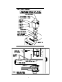
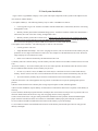
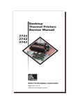
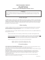
CROWN BOILER COMPANY
BWF SERIES BOILER
CATEGORY I VENT KIT
INSTALLATION AND OPERATING INSTRUCTIONS
WARNING
Improper installation, adjustment, alteration, service, or maintenance of this product can cause property damage,
injury, or loss of life. For assistance or additional information, consult a qualified installer, service agency, or the
gas supplier.
I Product Description
The BWF Category I vent kit is used to vent the BWF series boiler into a Category I (“Chimney”) vent system. This kit
consists of a special box-shaped adapter which is used to connect single wall smoke pipe or “B” vent to the fan discharge
of a BWF boiler. This adapter is equipped with a spill switch designed to shut down the burners and fan in the event of a
vent blockage. When connected to a properly sized and constructed vent system, all parts of the vent system, including
the adapter box, are under negative pressure.
II Before Installing
1) Read the installation instructions provided with the boiler. The instructions provided with the boiler cover all aspects
of the boiler installation except for venting. These instructions cover the installation of the Category I vent kit and
connection of the boiler to a Category I vent system.
2) Vent installation must be in accordance with the latest edition of the National Fuel Gas Code (NFPA54/ANSI Z223.1)
and all applicable local codes:
• Make sure that the boiler can be vented using a suitable chimney in accordance with all applicable codes.
• In the context of the National Fuel Gas Code, the BWF is classified as a Category I fan-assisted appliance only
when this kit is installed. When this kit is not installed, the BWF is classified as a Category III appliance and
must be vented using one of the stainless steel special vent systems shown in the installation manual.
• Make sure that you have the correct vent kit for the size boiler being installed:
BWF061 - BWF128: Crown #650140 (equipped with 5” collar)
BWF162 - BWF-229: Crown #650141 (equipped with 6” collar)
III Vent Kit Installation
1) Screw the four 10-32 studs supplied into the fan flange
2) Verify that the boiler model number marked on the outlet orifice matches that of the boiler being installed (see Fig. 1).
3) Slip a gasket, the outlet orifice, and the second gasket over the studs as shown in Figure 1.
4) Install the adapter box over the studs with the spill switch facing the right side of the boiler. Secure with the 10-32 nuts
and washers provided.
5) Route the wire harness from the spill switch into the boiler vestibule through knockout “A” shown in Figure 1.
6) Locate the 3/16 male/female quick-connect in the orange wire leading from the high limit. This quick-connect is
located near the right side of the vestibule where the conduit from the high limit enters the vestibule (Figure 2).
7) Unplug this quick connect.
8) Plug the spill switch harness into quick connects opened in Step 7 (also see connection and ladder diagrams).
9) Boiler is now ready to be connected to the vent system.
1
PN 980490 Rev. 0
2
IV Vent System Installation
Figure 3 shows a typical BWF Category I vent system. The major components of this system are the adapter box, the
vent connector, and the chimney.
1) Acceptable Chimneys - The following chimneys may be used to vent BWF series boilers:
•
Listed Type B or L gas vent - Install in accordance with the manufacturer’s instructions, the terms of its listing,
and applicable codes.
•
Masonry Chimney (lined with a listed metal lining system) - Install in accordance with the liner manufacturer’s
instructions, the terms of the liner’s listing, and applicable codes.
•
Masonry Chimney (lined with a ceramic liner) - In many cases, the National Fuel Gas Code does not permit
installation of fan assisted appliances such as the BWF into clay lined masonry chimneys. Consult the National Fuel
Gas Code before attempting to connect a BWF series boiler into a ceramic lined masonry chimney.
2) Acceptable Vent Connectors - The following may be used for vent connectors:
•
Listed type B or L Gas Vent
•
Single Wall Galvanized Pipe - Use 0.018” (26 gauge or heavier). The size and location of the chimney may not
permit the use of a single wall connector in some cases. See Chapter 10 of the National Fuel Gas Code. Do not use
single wall pipe for vent connectors in attics.
•
Other Vent Connectors Permitted by the National Fuel Gas Code.
3) Chimney and Vent Connector Sizing - Size the chimney and vent connector in accordance with the National Fuel Gas
Code.
4) Exterior Chimneys - An exterior chimney has one or more sides exposed to the outdoors below the roof line. There
are two conditions under which an exterior chimney may be used:
•
In some very restrictive cases, the BWF series boiler may be vented into an exterior ceramic lined masonry
chimney. See the National Fuel Gas Code for information on when exterior ceramic lined chimneys may be used.
•
An exterior masonry chimney may be used if it is lined with B vent or a listed chimney lining system.
5) Do not connect the vent of this appliance into any portion of a mechanical vent system operating under positive
pressure.
6) Do not connect the boiler into a chimney flue serving an open fireplace or other solid fuel appliance.
7) Prior to boiler installation, inspect chimney for obstructions or other defects and correct as required. Clean chimney as
necessary.
8) Vent connector should slope upward from the vent adapter box not less than 1/4 inch per foot. No portion of the vent
connector should run downward or have sags. All vent piping must be securely supported.
9) The vertical section of the vent pipe coming off the boiler should be as tall as possible, while still maintaining the
proper clearance from the horizontal vent connector to combustibles and the proper pitch called for in (9) above.
10) Vent connector should be installed above the bottom of the chimney to prevent blockage.
11) Vent connector must be inserted flush with inside face of the chimney liner and the space between vent pipe and
chimney sealed tight.
3
IV Removing an Existing Boiler from a Common Chimney
In some cases, when an existing boiler is removed from a common chimney, the common venting system may be too large
for the remaining appliances. At the time of removal of an existing boiler, the following steps shall be followed with each
appliance remaining connected to the common venting system placed in operation, while the other appliances remaining
connected to the common venting system are not in operation.
a) Seal any unused opening in the common venting system.
b) Visually inspect the venting system for proper size and horizontal pitch and determine there is no blockage or
restriction, leakage, corrosion and other deficiencies which could cause an unsafe condition.
c) Insofar as practical, close all building doors and windows and all doors between the space in which all the appliances
remaining connected to the common venting system are located and other spaces of the building. Turn on clothes
dryers and any appliance not connected to the common venting system. Turn on any exhaust fans, such as range
hoods and bathroom exhausts, so they will operate at maximum speed. Do not operate a summer exhaust fan. Close
fireplace dampers.
d) Place in operation the appliance being inspected. Follow the lighting instructions. Adjust thermostat so the
appliance will operate continuously.
e) Test for spillage at the draft hood relief opening after five (5) minutes of main burner operation. Use the flame of a
match or candle, or smoke from a cigarette, cigar, or pipe.
f) After it has been determined that each appliance remaining connected to the common venting system properly vents
when tested as outlined above, return doors, windows, exhaust fans, fireplace dampers and any other gas-burning
appliances to their previous condition of use.
g) Any improper operation of the common venting system should be corrected so the installation conforms with the
National Fuel Gas Code, ANSI Z223.1. When resizing any portion of the common venting system, the common
venting system should be resized to approach the minimum size as determined using the appropriate tables in Part 10
of the National Fuel Gas Code, ANSI Z223.1.
4
V Service and Maintenance
Perform all service and maintenance shown in the BWF installation manual. In addition, inspect the adapter box and
vent system for the following:
•
•
•
Blockages (including blockages in the blocked vent switch spillway)
Corrosion or other deterioration
Missing or loose supports
If the blocked vent switch opens, both the burners and fan will shut down. In order to restart the boiler, it will be
necessary to push the red reset button on the top of the spill switch.
WARNING
A shutdown of the boiler due to the blocked vent switch is an indication that there is a problem with the vent
system, such as a blockage
• Reset the switch only after a qualified heating technician has diagnosed and corrected the venting problem
that caused the switch to open.
• Do not replace the blocked vent switch with any other switch not specifically approved by Crown Boiler
Company for use on this vent kit.
5
VI Parts
(See Figure 1 for Illustrations)
DESCRIPTION
ADAPTER BOX (5" COLLAR)
ADAPTER BOX (6" COLLAR)
BLOCKED VENT SWITCH
B.V.S. HARNESS
CABLE CLAMP
#10 X 1/2 SHEET METAL SCREW
10-32 X 1" STUD
10-32 NUT
#10 FLAT WASHER
QTY. OR
CROWN P.N.
650145
650146
960650
960651
960655
90-212
900229
90-219A
90-057
6
KIT PART #
650140
USED WITH
BWF061 - BWF128
1 ea.
1 ea.
1 ea.
1 ea.
2 ea.
4 ea.
4 ea.
4 ea.
KIT PART #
650141
USED WITH
BWF162 - BWF229
1 ea.
1 ea.
1 ea.
1 ea.
2 ea.
4 ea.
4 ea.
4 ea.