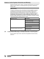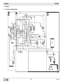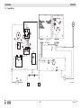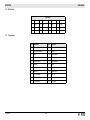
1
Operator’s Manual Portable Generator GPS 9700 EN 5200005190 5 2 0 0 01 0 0 0412 5 1 9 0 Copyright notice © Copyright 2012 by Wacker Neuson Production Americas LLC All rights, including copying and distribution rights, are reserved. This publication may be photocopied by the original purchaser of the machine. Any other type of reproduction is prohibited without express written permission from Wacker Neuson Production Americas LLC. Any type of reproduction or distribution not authorized by Wacker Neuson Production Americas LLC represents an infringement of valid copyrights. Violators will be prosecuted. Trademarks All trademarks referenced in this manual are the property of their respective owners. Manufacturer Wacker Neuson Production Americas LLC N92W15000 Anthony Avenue Menomonee Falls, WI 53051 U.S.A. Tel: (262) 255-0500 · Fax: (262) 255-0550 · Tel: (800) 770-0957 www.wackerneuson.com Original instructions This Operator’s Manual presents the original instructions. The original language of this Operator’s Manual is American English. GPS 9700 Foreword Foreword SAVE THESE INSTRUCTIONS—This manual contains important instructions for the machine models listed below. These instructions must be followed during installation and maintenance of the generator (and battery, if equipped). Machines covered in this manual Machine documentation Expectations for information in this manual Machine Item Number GPS 9700 5200005042 From this point forward in this documentation, Wacker Neuson Production Americas LLC will be referred to as Wacker Neuson. Keep a copy of the Operator’s Manual with the machine at all times. Use the separate Parts Book supplied with the machine to order replacement parts. Refer to the separate Repair Manual for detailed instructions on servicing and repairing the machine. If you are missing any of these documents, please contact Wacker Neuson to order a replacement or visit www.wackerneuson.com. When ordering parts or requesting service information, be prepared to provide the machine model number, item number, revision number, and serial number. This manual provides information and procedures to safely operate and maintain the above Wacker Neuson model(s). For your own safety and to reduce the risk of injury, carefully read, understand, and observe all instructions described in this manual. Wacker Neuson expressly reserves the right to make technical modifications, even without notice, which improve the performance or safety standards of its machines. The information contained in this manual is based on machines manufactured up until the time of publication. Wacker Neuson reserves the right to change any portion of this information without notice. CALIFORNIA Proposition 65 Warning Engine exhaust, some of its constituents, and certain vehicle components, contain or emit chemicals known to the State of California to cause cancer and birth defects or other reproductive harm. Laws pertaining to spark arresters NOTICE: State Health Safety Codes and Public Resources Codes specify that in certain locations spark arresters be used on internal combustion engines that use hydrocarbon fuels. A spark arrester is a device designed to prevent accidental discharge of sparks or flames from the engine exhaust. Spark arresters are qualified and rated by the United States Forest Service for this purpose. In order to comply with local laws regarding spark arresters, consult the engine distributor or the local Health and Safety Administrator. wc_tx003011gb.fm 3 Foreword GPS 9700 Manufacturer’s This manual contains references to approved parts, attachments, and modificaapproval tions. The following definitions apply: Approved parts or attachments are those either manufactured or provided by Wacker Neuson. Approved modifications are those performed by an authorized Wacker Neuson service center according to written instructions published by Wacker Neuson. Unapproved parts, attachments, and modifications are those that do not meet the approved criteria. Unapproved parts, attachments, or modifications may have the following consequences: Serious injury hazards to the operator and persons in the work area Permanent damage to the machine which will not be covered under warranty Contact your Wacker Neuson dealer immediately if you have questions about approved or unapproved parts, attachments, or modifications. 4 wc_tx003011gb.fm GPS 9700 1 Foreword 3 Safety Information 7 1.1 1.2 1.3 1.4 1.5 2 Signal Words Used in this Manual ....................................................... 7 Machine Description and Intended Use ............................................... 8 Operating Safety .................................................................................. 9 Operator Safety while Using Internal Combustion Engines ............... 12 Service Safety .................................................................................... 13 Labels 2.1 2.2 3 Table of Contents 15 Label Locations .................................................................................. 15 Label Meanings .................................................................................. 16 Operation 3.1 3.2 3.3 3.4 3.5 3.6 3.7 3.8 3.9 3.10 3.11 3.12 3.13 3.14 3.15 3.16 3.17 3.18 21 Lifting and Transporting ...................................................................... 22 Determining Power Requirements ..................................................... 23 Installation .......................................................................................... 24 Generator Derating ............................................................................. 25 Grounding the Generator ................................................................... 26 Use of Extension Cords ...................................................................... 27 Recommended Battery ....................................................................... 27 Control Panel ...................................................................................... 28 Main Circuit Breaker ........................................................................... 29 Ground Fault Interrupt (GFI / GFCI) ................................................... 29 Voltage Selector Switch ..................................................................... 30 240V Twist-Lock Receptacles ............................................................ 30 Engine Auto Idle ................................................................................. 31 Engine Speed ..................................................................................... 31 Before Starting ................................................................................... 32 Starting ............................................................................................... 33 Stopping ............................................................................................. 34 Emergency Shutdown Procedure ....................................................... 34 wc_bo5200005190_01TOC.fm 5 Table of Contents 4 Maintenance 4.1 4.2 4.3 4.4 4.5 4.6 4.7 4.8 4.9 4.10 4.11 5 Maintaining the Emission Control System ...........................................35 Periodic Maintenance Schedule ..........................................................35 Engine Oil ............................................................................................36 Oil Filter ...............................................................................................37 Servicing the Air Cleaner .....................................................................38 Spark Plug ...........................................................................................39 Fuel Filter ............................................................................................40 Carburetor Adjustment ........................................................................41 Long-Term Storage .............................................................................41 Transporting the Machine ....................................................................42 Troubleshooting ...................................................................................42 43 Generator ............................................................................................43 Engine .................................................................................................44 Emission Control Systems Information and Warranty 6.1 6.2 6.3 6.4 6.5 7 35 Technical Data 5.1 5.2 6 GPS 9700 Emission Control System Background Information .............................45 Limited Defect Warranty for Exhaust Emission Control System .........46 Limited Defect Warranty for Wacker Neuson Evaporative Emission Control Systems ..................................................................46 California Evaporative Emission Control Warranty Statement ............49 Limited Defect Warranty for Exhaust Emission Control System .........50 Schematics 7.1 7.2 7.3 7.4 7.5 7.6 45 52 Generator and Receptacle Wiring .......................................................52 Wire Colors ..........................................................................................53 Components ........................................................................................53 Engine Wiring ......................................................................................54 Wire Colors ..........................................................................................55 Components ........................................................................................55 6 wc_bo5200005190_01TOC.fm GPS 9700 1 1.1 Safety Information Safety Information Signal Words Used in this Manual This manual contains DANGER, WARNING, CAUTION, NOTICE, and NOTE signal words which must be followed to reduce the possibility of personal injury, damage to the equipment, or improper service. This is the safety alert symbol. It is used to alert you to potential personal hazards. f Obey all safety messages that follow this symbol. DANGER DANGER indicates a hazardous situation which, if not avoided, will result in death or serious injury. f To avoid death or serious injury from this type of hazard, obey all safety messages that follow this signal word. WARNING WARNING indicates a hazardous situation which, if not avoided, could result in death or serious injury. f To avoid possible death or serious injury from this type of hazard, obey all safety messages that follow this signal word. CAUTION CAUTION indicates a hazardous situation which, if not avoided, could result in minor or moderate injury. f To avoid possible minor or moderate injury from this type of hazard, obey all safety messages that follow this signal word. NOTICE: Used without the safety alert symbol, NOTICE indicates a situation which, if not avoided, could result in property damage. Note: A Note contains additional information important to a procedure. wc_si000671gb.fm 7 Safety Information 1.2 GPS 9700 Machine Description and Intended Use This machine is a portable electric power source. The Wacker Neuson Portable Generator consists of a tubular steel frame surrounding a fuel tank, a gasoline engine, a control panel, and an electric alternator. The control panel includes controls and receptacles. As the engine runs, the generator converts mechanical energy into electric power. The operator connects loads to the electric power receptacles. This machine is intended for the purpose of supplying electrical power to connected loads. Refer to the product specifications for the output voltage and frequency of this generator, and the maximum output power limit of this generator. This machine has been designed and built strictly for the intended use described above. Using the machine for any other purpose could permanently damage the machine or seriously injure the operator or other persons in the area. Machine damage caused by misuse is not covered under warranty. The following are some examples of misuse: Connecting a load that has voltage and frequency requirements that are incompatible with the generator output Overloading the generator with a load that draws excessive power during either continuous running or start-up Operating the generator in a manner that is inconsistent with all federal, state and local codes and regulations Using the machine as a ladder, support, or work surface Using the machine to carry or transport passengers or equipment Operating the machine outside of factory specifications Operating the machine in a manner inconsistent with all warnings found on the machine and in the Operator’s Manual. This machine has been designed and built in accordance with the latest global safety standards. It has been carefully engineered to eliminate hazards as far as practicable and to increase operator safety through protective guards and labeling. However, some risks may remain even after protective measures have been taken. They are called residual risks. On this machine, they may include exposure to: Heat, noise, exhaust, and carbon monoxide from the engine Fire hazards from improper refueling techniques Fuel and its fumes Electric shock and arc flash Personal injury from improper lifting techniques To protect yourself and others, make sure you thoroughly read and understand the safety information presented in this manual before operating the machine. 8 wc_si000671gb.fm GPS 9700 1.3 Safety Information Operating Safety DANGER Carbon monoxide. Using a generator indoors CAN KILL YOU IN MINUTES. Generator exhaust contains carbon monoxide (CO). This is a poison you cannot see or smell. If you can smell the generator exhaust, you are breathing CO. But even if you cannot smell the exhaust, you could be breathing CO. f NEVER use a generator inside homes, garages, crawlspaces, or other partly enclosed areas. Deadly levels of carbon monoxide can build up in these areas. Using a fan or opening windows and doors does NOT supply enough fresh air. f ONLY use a generator outside and far away from windows, doors, and vents. These openings can pull in generator exhaust. f Even when you use a generator correctly, CO may leak into the home. ALWAYS use a battery-powered or battery-backup CO alarm in the home. f If you start to feel sick, dizzy, or weak after the generator has been running, move to fresh air RIGHT AWAY. See a doctor. You could have carbon monoxide poison. Operator training Before operating the machine: Read and understand the operating instructions contained in all manuals delivered with the machine. Familiarize yourself with the location and proper use of all controls and safety devices. Contact Wacker Neuson for additional training if necessary. When operating this machine: Do not allow improperly trained people to operate the machine. People operating the machine must be familiar with the potential risks and hazards associated with it. Operator qualifications Only trained personnel are permitted to start, operate, and shut down the machine. They also must meet the following qualifications: have received instruction on how to properly use the machine are familiar with required safety devices The machine must not be accessed or operated by: children people impaired by alcohol or drugs Application area Be aware of the application area. Keep unauthorized personnel, children, and pets away from the machine. Remain aware of changing positions and the movement of other equipment and personnel in the application area/job site. Be aware of the application area. Do not operate the machine in areas that contain flammable objects, fuels, or products that produce flammable vapors. wc_si000671gb.fm 9 Safety Information Safety devices, controls, and attachments GPS 9700 Only operate the machine when: All safety devices and guards are in place and in working order. All controls operate correctly. The machine is set up correctly according to the instructions in the Operator’s Manual. The machine is clean. The machine’s labels are legible. To ensure safe operation of the machine: Do not operate the machine if any safety devices or guards are missing or inoperative. Do not modify or defeat the safety devices. Only use accessories or attachments that are approved by Wacker Neuson. Safe operating practices When operating this machine: Remain aware of the machine’s moving parts. Keep hands, feet, and loose clothing away from the machine’s moving parts. When operating this machine: Do not operate a machine in need of repair. Personal Protective Equipment (PPE) Wear the following Personal Protective Equipment (PPE) while operating this machine: Close-fitting work clothes that do not hinder movement Safety glasses with side shields Hearing protection Safety-toed footwear Installing as Special hazards exist when installing this machine as a backup power supply. backup power Improper connection of generator to a building’s electrical system can allow electrical current from the generator to backfeed into utility lines. This may result in electrocution of utility workers, fire, or explosion. WARNING Backfeed from the generator into the public power distribution system can cause serious injury or death to utility workers! f Connections to a building’s electrical system must be made by a qualified electrician and comply with all applicable laws and electrical codes. If connected to a building’s electrical system, the generator must meet the power, voltage, and frequency requirements of the equipment in the building. Differences in power, voltage, and frequency requirements may exist and improper connection may lead to equipment damage, fire, and personal injury or death. 10 wc_si000671gb.fm GPS 9700 Transporting and installing the machine Safety Information General Safety Generator vibration After use = Cleaning Never allow untrained personnel to operate or service the generator. The generator set should be set up by a certified electrician. Do not stand under the machine while it is being hoisted or moved. Do not attach equipment to the machine when it is suspended. Always transport the generator in an upright position. Always position and operate the generator on a firm, noncombustible, level surface. Always make certain the machine is well-grounded and securely fastened to a good earthen ground per national and local regulations. Always remove all tools, cords, and other loose items from the generator before starting it. Do not operate the generator when open containers of fuel, paint, or other flammable liquids are near. Do not operate the generator, or tools attached to the generator, with wet hands. Do not run the electrical cords under the generator, or over vibrating or hot parts. Do not enclose or cover the generator when it is in use or when it is hot. Do not overload the generator. The total amperage of the tools and equipment attached to the generator must not exceed the load rating of the generator. Do not operate the machine in snow, rain, or standing water. Do not stand on the machine. Generators vibrate in normal use. During and after the use of the generator, inspect the generator as well as extension cords and power supply cords connected to it for damage from vibration. Have damaged items repaired or replaced as necessary. Do not use plugs or or cords that show signs of damage such as broken or cracked insulation or damaged blades. Store the machine properly when it is not being used. The machine should be stored in a clean, dry location out of the reach of children. When cleaning and servicing the machine: Keep the machine clean and free of debris such as leaves, paper, cartons, etc. Keep the labels legible. When cleaning the machine: Do not clean the machine while it is running. Never use gasoline or other types of fuels or flammable solvents to clean the machine. Fumes from fuels and solvents can become explosive. wc_si000671gb.fm 11 Safety Information 1.4 GPS 9700 Operator Safety while Using Internal Combustion Engines WARNING Internal combustion engines present special hazards during operation and fueling. Failure to follow the warnings and safety standards could result in severe injury or death. f Read and follow the warning instructions in the engine owner’s manual and the safety guidelines below. DANGER f Carbon monoxide. Using a generator indoors CAN KILL YOU IN MINUTES. Generator exhaust contains carbon monoxide (CO). This is a poison you cannot see or smell. If you can smell the generator exhaust, you are breathing CO. But even if you cannot smell the exhaust, you could be breathing CO. Refueling safety When refueling the engine: Do not smoke. Do not refuel if the generator is sitting in a truck fitted with a plastic bed liner. Static electricity can ignite the fuel or fuel vapors. Do not refuel a hot or running engine. Do not refuel the engine near an open flame. When refueling the engine, always: Refill the fuel tank in a well-ventilated area. Replace the fuel tank cap after refueling. Operating safety When operating the generator: Check the fuel lines and the fuel tank for leaks and cracks before starting the engine. Do not run the machine if fuel leaks are present or the fuel lines are loose. Do not run the engine near open flames. Do not start the engine if fuel has spilled or a fuel odor is present. Move the generator away from the spill and wipe the generator dry before starting. Do not smoke while operating the machine. 12 wc_si000671gb.fm GPS 9700 1.5 Safety Information Service Safety Service training Before servicing or maintaining the machine: Read and understand the instructions contained in all manuals delivered with the machine. Familiarize yourself with the location and proper use of all controls and safety devices. Only trained personnel shall troubleshoot or repair problems occurring with the machine. Contact Wacker Neuson for additional training if necessary. When servicing or maintaining this machine: Do not allow improperly trained people to service or maintain the machine. Personnel servicing or maintaining the machine must be familiar with the associated potential risks and hazards. Precautions Follow the precautions below when servicing or maintaining the machine. Read and understand the service procedures before performing any service to the machine. All adjustments and repairs must be completed before operating the machine. Do not operate the machine with a known problem or deficiency. All repairs and adjustments shall be completed by a qualified technician. Turn off the machine before performing maintenance or making repairs. Remain aware of the machine’s moving parts. Keep hands, feet, and loose clothing away from the machine’s moving parts. Reinstall the safety devices and guards after repair and maintenance procedures are complete. Machine modifications When servicing or maintaining the machine: Use only accessories/attachments that are approved by Wacker Neuson. When servicing or maintaining the machine: Do not defeat safety devices. Do not modify the machine without the express written approval of Wacker Neuson. Replacing parts and labels wc_si000671gb.fm Replace worn or damaged components. Replace all missing and hard-to-read labels. When replacing electrical components, use components that are identical in rating and performance to the original components. When replacement parts are required for this machine, use only Wacker Neuson replacement parts or those parts equivalent to the original in all types of specifications, such as physical dimensions, type, strength, and material. 13 Safety Information Cleaning GPS 9700 When cleaning and servicing the machine: Keep the machine clean and free of debris such as leaves, paper, cartons, etc. Keep the labels legible. When cleaning the machine: Do not clean the machine while it is running. Never use gasoline or other types of fuels or flammable solvents to clean the machine. Fumes from fuels and solvents can become explosive. Personal Protective Equipment (PPE) Wear the following Personal Protective Equipment (PPE) while servicing or maintaining this machine: Close-fitting work clothes that do not hinder movement Safety glasses with side shields Hearing protection Safety-toed footwear In addition, before servicing or maintaining the machine: Tie back long hair. Remove all jewelry (including rings). Precautions Do not allow water to accumulate around the base of the machine. If water is present, move the machine and allow the machine to dry before servicing. Do not service the machine if your clothing or skin is wet. Always turn the engine off before servicing the machine. If the engine has electric start, disconnect the negative terminal on the battery before servicing the machine. Always let the engine cool before transporting or servicing the machine. 14 wc_si000671gb.fm GPS 9700 2 2.1 Labels Labels Label Locations H C Q J A,B G L O D M P F E K wc_si000672gb.fm 15 Labels 2.2 GPS 9700 Label Meanings Wacker Neuson machines use international pictorial labels where needed. These labels are described below. WARNING! Hot surface B CAUTION! Read and understand the supplied Operator’s Manual before operating this machine. Failure to do so increases the risk of injury to yourself and others. C NOTICE Lifting point. D Electrical ground GND 88897 A E Neutral bonded to frame. F Key switch: off on start 16 wc_si000672gb.fm GPS 9700 G Labels 1 2 3 4 6 7 5A 5B 1 2 3 Open main circuit breaker. Open the fuel flow valve. Open the choke. Turn engine key switch to “ON” position. Pull rewind starter or turn engine key switch to crank starter. Close main circuit breaker. wc_si000672gb.fm 17 Labels GPS 9700 — Close the fuel flow valve. Close the choke. Turn engine key switch to “OFF” position. H, J DANGER Using a generator indoors CAN KILL YOU IN MINUTES. Generator exhaust contains carbon monoxide. This is a poison you cannot see or smell. — NEVER use inside a home or garage, EVEN IF doors and windows are open. — Only use OUTSIDE and far away from windows, doors, and vents. K IMPORTANT EMISSIONS INFORMATION THIS EQUIPMENT MEETS XXXX CALIFORNIA EVP EMISSION REGULATIONS FOR SMALL OFF-ROAD ENGINES. YOM: XXXX Important Emissions Information This equipment meets California EVP emission regulations for small off-road engines. J F M A M J J A S O N D 18 wc_si000672gb.fm GPS 9700 Labels L Improper connection of generator to a building’s electrical system can allow electrical current from the generator to backfeed into utility lines. This may result in electrocution of utility workers, fire, or explosion. Connections to a building’s electrical system must be made by a qualified electrician and comply with all applicable laws and electrical codes. Do not run the engine near open flames. M Emission Control Information This equipment meets U.S. EPA EVAP standards. Evaporative Family: CWIXNHEQCL2 Exempt from tank permeation standards under 40 CFR 1054.145. CWIXNHEQCL2 5200003299 O A nameplate listing the model number, item number, revision number, and serial number is attached to each unit. Please record the information found on this nameplate so it will be available should the nameplate become lost or damaged. When ordering parts or requesting service information, you will always be asked to specify the model number, item number, revision number, and serial number of the unit. P GFCI TEST INSTRUCTIONS - TEST BEFORE EACH USE Normal operating state - sensing device green LED is "ON" and circuit breaker is at "ON" position. Step 1: Press "TEST" button. Green LED should go "OUT" and red LED should come "ON" and circuit breaker should trigger to "OFF" position. Step 2: If sensing device LED or breaker does not trip or change state, "DO NOT USE". Consult an electrician for assistance. Step 3: Press "RESET" button. Red LED should turn "OFF" and green LED should turn "ON". Step 4: Manually reset (switch) circuit breaker to "ON" position to restore circuit power. wc_si000672gb.fm 19 Labels GFCI TEST INSTRUCTIONS - TEST BEFORE EACH USE DANGER PELIGRO STOP 5200005862 Q GPS 9700 DANGER DANGER! Read the Operator’s Manual. No sparks, flames, or burning objects near the machine. Stop the engine before refueling. GFCI TEST INSTRUCTIONS - TEST BEFORE EACH USE Normal operating state - sensing device green LED is "ON" and circuit breaker is at "ON" position. Step 1: Press "TEST" button. Green LED should go "OUT" and red LED should come "ON" and circuit breaker should trigger to "OFF" position. Step 2: If sensing device LED or breaker does not trip or change state, "DO NOT USE". Consult an electrician for assistance. Step 3: Press "RESET" button. Red LED should turn "OFF" and green LED should turn "ON". Step 4: Manually reset (switch) circuit breaker to "ON" position to restore circuit power. 20 wc_si000672gb.fm GPS 9700 3 Operation Operation DANGER Carbon monoxide. Using a generator indoors CAN KILL YOU IN MINUTES. Generator exhaust contains carbon monoxide (CO). This is a poison you cannot see or smell. If you can smell the generator exhaust, you are breathing CO. But even if you cannot smell the exhaust, you could be breathing CO. f NEVER use a generator inside homes, garages, crawlspaces, or other partly enclosed areas. Deadly levels of carbon monoxide can build up in these areas. Using a fan or opening windows and doors does NOT supply enough fresh air. f ONLY use a generator outside and far away from windows, doors, and vents. These openings can pull in generator exhaust. f Even when you use a generator correctly, CO may leak into the home. ALWAYS use a battery-powered or battery-backup CO alarm in the home. f If you start to feel sick, dizzy, or weak after the generator has been running, move to fresh air RIGHT AWAY. See a doctor. You could have carbon monoxide poison. Preparing for first use To prepare your machine for first use: wc_tx000954gb.fm 3.0.1 Make sure all loose packaging materials have been removed from the machine. 3.0.2 Check the machine and its components for damage. If there is visible damage, do not operate the machine! Contact your Wacker Neuson dealer immediately for assistance. 3.0.3 Take inventory of all items included with the machine and verify that all loose components and fasteners are accounted for. 3.0.4 Attach component parts not already attached. 3.0.5 Add fluids as needed and applicable, including fuel, engine oil, and battery acid. 3.0.6 Move the machine to its operating location. 21 Operation 3.1 GPS 9700 Lifting and Transporting Lifting the Machine This generator, while compact, is heavy enough to cause injury if proper lifting techniques are not used. Observe the following guidelines when lifting the generator. • Do not attempt to lift and carry the generator unassisted. Use appropriate lifting equipment such as slings, chains, hooks, ramps, or jacks. • Make sure lifting equipment is attached securely and has enough weight-bearing capacity to lift or hold the generator safely. • Remain aware of the location of other people nearby when lifting the generator. Transporting the Machine Observe the following guidelines when transporting the generator to and from the job site. • Allow the engine to cool before transporting the generator. • Drain the fuel tank. • Close the fuel valve. • Ensure that the generator is securely strapped down in the transport vehicle to prevent it from sliding or tipping. • Do not refuel the generator in or on the transport vehicle. Move the generator to its operating location and then fill the fuel tank. 22 wc_tx000954gb.fm GPS 9700 3.2 Operation Determining Power Requirements This generator is designed to operate single-phase, 60 Hz appliances running at 120 and 240 VAC. NOTICE: Do not exceed the continuous rated output of the generator. Damage to tools or generator will occur. See Technical Data. Check the nameplate or label provided on tools and appliances to make sure their power requirements are met by the power output of the generator. If the wattage is not given for a particular tool or appliance, contact the tool manufacturer for wattage requirements. Some appliances and tools require a surge of current when starting. This means that the amount of power needed to initially start the equipment is larger than the power required to keep it running. The generator must be capable of supplying this "surge" current. Other types of appliances require more power than is actually stated on their nameplate. The information in “Approximate Starting Power Requirements” is offered only as a general guideline to help you determine power requirements for different types of equipment. Check with your nearest Wacker dealer, or contact the manufacturer or dealer of the tool or appliance, if you have questions regarding power requirements. Approximate Starting Power Requirements • Incandescent lights and appliances such as irons and hot plates, which use a resistive-type heating element, require the same wattage to start and run as is stated on their nameplates. • Fluorescent and mercury lamps require 1.2–2 times their stated wattage to start. • Electrical motors and many types of electrical tools often require a large starting current. The amount of starting current depends on the type of motor and its use. • Most electrical tools require 1.2–3 times their stated wattage for starting. • Loads such as submersible pumps and air compressors require a very large force to start. They need as much as 3–5 times the wattage stated on the nameplate in order to start. If the wattage is not given for a particular tool or appliance, it can be calculated by multiplying its voltage and amperage requirements: Single Phase: VOLTS x AMPS = WATTS Three Phase: VOLTS x AMPS x 1.732 x 0.8 = WATTS wc_tx000954gb.fm 23 Operation 3.3 GPS 9700 Installation Place the generator in an area where it will not be exposed to rain, snow, or direct sunlight. Make sure it is positioned on firm, level ground, so it will not slide or shift. Position the engine exhaust away from areas where people may be present. The surrounding area must be free from water and moisture. All components must be protected from excessive moisture. 24 wc_tx000954gb.fm GPS 9700 3.4 Operation Generator Derating All generators are subject to derating for altitude and temperature. Internal combustion engines, unless modified, run less efficiently at higher altitudes due to the reduction of air pressure. This translates into a lack of power and thus reduction in generator output. Temperature affects both engine and generator performance. As temperature increases, an engine will run less efficiently and more resistance will be found in electrical components. Therefore, as the temperature increases, the output of the generator decreases. Altitude also affects the cooling capacity of air—the higher the altitude the less dense the air is and thus the lower its ability to transfer heat. For every increase in altitude of 500 m (1650 ft.) above 1000 m (3300 ft.), the output of the generator will be reduced by 3%. For every increase of 5° C (9° F) in ambient temperature above 40° C (104° F), the output of the generator will be reduced by 3%. Use the tables shown for altitude and temperature deration factors. It may be necessary to consider both altitude and ambient temperature deration factors to determine true generator output. wc_tx000954gb.fm Ambient Temp. °C (°F) Derate Factor 45 (113) 3% 0.97 50 (122) 6% 0.94 55 (131) 9% 0.91 60 (140) 12 % 0.88 Altitude m (ft.) Derate Factor 1500 (4900) 3% 0.97 2000 (6600) 6% 0.94 2500 (8200) 9% 0.91 3000 (9900) 12 % 0.88 3500 (11500) 15 % 0.85 4000 (13100) 18 % 0.82 25 Operation 3.5 GPS 9700 Grounding the Generator Location A ground connection (a) is located on the generator frame. wc_gr000544 Function This ground connection is used for electrically grounding the generator when necessary to comply with the National Electrical Code and other federal, state, and local regulations. For grounding requirements in your area, consult with a qualified electrician, electrical inspector, or local agency having jurisdiction over electrical compliance. • If the generator is used at a construction site, there may be additional regulations which must be observed. • In some areas, generators are required to be registered with local utility companies. • There is a conductor between the generator (stator neutral winding) and the frame. 26 wc_tx000954gb.fm GPS 9700 3.6 Operation Use of Extension Cords WARNING Current When a long extension cord is used to connect an appliance or tool to the generator, a voltage loss occurs—the longer the cord, the greater the voltage loss. This results in less voltage being supplied to the appliance or tool and increases the amount of current draw or reduces performance. A heavier cord with a larger wire size will reduce the voltage loss. Damaged extension cords can cause electrical shock, resulting in serious injury or death. DO NOT use worn, bare, or frayed cords. Replace damaged cords immediately. Use the chart below as a guide for selecting proper cable size. Load in Watts Maximum Cable Length in Feet (Amps) 120V 240V #10 #12 #14 #16 2.5 300 600 1000. 600 375 250 5 600 1200 500 300 200 125 7.5 900 1800 350 200 125 100 10 1200 2400 250 150 100 - 15 1800 3600 150 100 65 - 20 2400 4800 125 75 50 - Use only extension cords rated for outdoor use and equipped with a third-wire ground. NOTICE: Operating equipment at low voltage can cause it to overheat. 3.7 Recommended Battery This generator is shipped without a battery. The recommended battery to be used is: wc_tx000954gb.fm Battery Type 22NF Voltage 12V Capacity 225 Cold Cranking Amps 27 Operation 3.8 GPS 9700 Control Panel Ref. Description Ref. a Auto Idle Switch h Voltage Selector Switch b Main Circuit Breaker j 120V 30A Twist-lock Receptacle c 240V 20A Overcurrent Circuit Breaker k 120/240 30A Twist-lock Receptacle d 120/240V 30A Overcurrent Circuit Breaker m 240V 20A Twist-lock Receptacle e Hour meter n 120/240V Twist-lock Receptacle f 120V Duplex Receptacle o GFI Test / Reset g Thermal Overload — — c d a Description e o1 o o2 j b g h g g f f m k wc_gr008311 28 wc_tx000954gb.fm GPS 9700 3.9 Operation Main Circuit Breaker The generator is protected by a main breaker (b) located on the control panel. The circuit breaker protects the generator from severe overloads or short circuits. If the circuit breaker opens, turn the engine off immediately and determine the cause before restarting. Check the appliances and tools attached to the generator for defects and make sure their power requirements do not exceed the power rating of the generator or the current limit of the receptacles. When the circuit breaker opens (O), the breaker lever will snap down. To reset circuit breaker, lift lever up (l). 3.10 Ground Fault Interrupt (GFI / GFCI) The receptacles on this machine are protected by both a ground fault interrupt (GFI) and thermal overloads. The GFI shuts off power to the circuit when a ground fault occurs in the generator or a piece of equipment attached to the generator. The thermal overload (g) will trip (pop out) if too much current is drawn through the receptacles, as in a short to ground. The GFI should be tested for proper operation every time the generator is used. To test GFI: Start generator. Place main circuit breaker in closed position. Turn auto idle “OFF” (O). Push TEST button (o1) on receptacle in. The RESET button (o2) will pop out. Power is now off at the receptacles. If the RESET button does not pop out, the GFI is not working. Do not run generator until the problem can be corrected. To restore power to receptacles, push the RESET button in. If the RESET button pops out during operation, stop the generator and check generator and equipment for defects. wc_tx000954gb.fm 29 Operation 3.11 GPS 9700 Voltage Selector Switch The voltage selector switch (h) allows the generator to operate in either single (120V) or dual voltage (120/240V) mode. In single voltage mode only the 120V twist lock and 120V duplex receptacles are powered. The full rated power of the generator is shared between the four receptacles. In dual voltage mode both the 120V and 240V receptacles are powered; however, only half the rated power is available at the 120V GFI receptacles and half at the 120V twist lock receptacle. Full power is available at the 240V twist lock receptacle. NOTICE: NEVER switch the voltage selector switch with the main breaker on! This can cause arcing and can damage the generator. Turn all tools and appliances off and place main breaker in the “OFF” (open) position (O) before changing the voltage switch position. 3.12 240V Twist-Lock Receptacles 240 volt power is available at twist-lock receptacles (m) and (n). 120 volt power is also available at twist-lock receptacle (n) and at receptacles (j) and (k). The thermal overloads for (j) and (k) perform as described for (g) in GFI. However, protection for the 240V receptacles is provided by overcurrent circuit breakers, (c) for (m) and (d) for (n). If too much current were to be drawn through either overcurrent circuit breaker, the breaker would trip open. Correct the source of the overcurrent before resetting the breaker. To attach a power cord to a twist-lock receptacle, insert plug into receptacle and turn it clockwise to lock it in place. 30 wc_tx000954gb.fm GPS 9700 3.13 Operation Engine Auto Idle The auto idle switch (a) automatically reduces engine speed 5 seconds after all appliances or tools attached to the generator have been turned off. Engine automatically returns to full speed when a tool or appliance is turned back on. To turn auto idle feature on, push auto idle switch to ON (I). This position is recommended while the generator is running to minimize fuel consumption. To avoid extended engine warm-up periods, keep switch OFF (O) when starting the engine and until engine reaches operating temperature. 3.14 Engine Speed Generators require a fixed engine speed to maintain the correct voltage. Engine speed is controlled by a governor which automatically adjusts to varying loads on the engine to maintain a constant speed of 3600 rpm. There is no throttle control. Use the Auto Idle switch on the generator to control engine speed. Note: The battery must have the appropriate charge (nine volts minimum) for the generator governor to perform properly. If the generator starts but will not run at speed, check battery charge. wc_tx000954gb.fm 31 Operation 3.15 GPS 9700 Before Starting DANGER f Carbon monoxide. Using a generator indoors CAN KILL YOU IN MINUTES. Generator exhaust contains carbon monoxide (CO). This is a poison you cannot see or smell. If you can smell the generator exhaust, you are breathing CO. But even if you cannot smell the exhaust, you could be breathing CO. 3.15.1 Read and understand safety and operating instructions at beginning of this manual. 3.15.2 Read and understand the meanings of all warning and operating labels. 3.15.3 Make sure that a battery has been installed. See Technical Data. 3.15.4 The generator is shipped and delivered dry (without battery acid). If the generator is being run for the first time, fill the battery cells with acid. 3.15.5 Check: • oil level in engine • fuel level • condition of air cleaner • tightness of external fasteners • condition of fuel lines • battery acid level—add distilled water if necessary 3.15.6 Fill the fuel tank with fresh, regular, unleaded grade gasoline. DO NOT use an oil/gas mixture. The use of gasohol or any fuel containing more than 10% ethanol is not recommended. Consult the engine owner's manual for complete fuel specifications. NOTICE: Fill the tank after placing the machine on level ground. 32 wc_tx000954gb.fm GPS 9700 3.16 Operation Starting Follow instructions below and read starting and stopping instuctions found in Engine Owner’s Manual. 3.16.1 Ensure that the generator is properly installed in an outdoor location. See Sections Installation and Operator Safety while using Internal Combustion Engines for installation warnings and safety guidelines. 3.16.2 Disconnect all loads from the generator and place the main circuit breaker in the open (O) position. Place auto idle switch to OFF (O) position. 3.16.3 Open fuel valve (b1). 3.16.4 If engine is cold, pull choke control out (a1). If engine is hot, push choke control in (a2). 3.16.5 Turn key switch to the start position (d3) and hold until engine starts. NOTICE: Do not crank engine longer than 15 seconds at a time. Extended cranking can damage starter motor. To start engine using manual start: Turn key switch to the run position (d2). Pull starter rope (c) rapidly to start engine. Leave key in run position (d2) while engine is running. Note: Turn the keyswitch to the OFF position when the engine is not running. Leaving the key in the RUN position with the engine off will drain the battery. Note: Although the engine will start manually and will run without a battery, it will only idle and the generator will not load, as the governor requires that a battery be connected. See “Recommended Battery.” Note: The engine is equipped with a low oil protection system. If the oil level is low, the engine will not start. Check engine oil level if engine does not start. wc_tx000954gb.fm 3.16.6 Push choke in as engine warms (a2). 3.16.7 Place main circuit breaker in closed (l) position and place auto idle switch in ON (l) position. Allow engine to warm up and check function of GFI circuit breakers before attaching loads to generator (see Ground Fault Circuit Interrupt). 33 Operation 3.17 GPS 9700 Stopping 3.17.1 Disconnect all loads from generator and place main circuit breaker in open position. 3.17.2 Turn engine switch to the stop position (d1). 3.17.3 Close fuel valve (b2). 3.18 Emergency Shutdown Procedure Procedure If a breakdown or accident occurs while the machine is operating, follow the procedure below: 3.18.1 Stop the engine. 3.18.2 Turn off the fuel supply. 3.18.3 Disconnect tools from the machine. 3.18.4 Allow the machine to cool. 3.18.5 Contact the rental yard or machine owner for further instructions. 34 wc_tx000954gb.fm GPS 9700 4 Maintenance Maintenance 4.1 Maintaining the Emission Control System Normal maintenance, replacement, or repair of emission control devices and systems may be performed by any repair establishment or individual; however, warranty repairs must be performed by a dealer/service center authorized by Wacker Neuson. The use of service parts that are not equivalent in performance and durability to authorized parts may impair the effectiveness of the emission control system and may have a bearing on the outcome of a warranty claim. 4.2 Periodic Maintenance Schedule The table below lists basic machine and engine maintenance. Tasks designated with check marks may be performed by the operator. Tasks designated with square bullet points require special training and equipment. Refer to the engine owner’s manual for additional information. Daily before starting Check fuel level. 3 Check engine oil level. 3 Inspect fuel lines. 3 Inspect air filter. Clean as needed. 3 Check external hardware. 3 Change engine oil.* After first 5 hrs. Every 50 hrs. Check shockmounts. Replace when necessary. Every 100 hrs. Every year Replace oil filter.* Check and clean spark plug. Replace air cleaner.* Check and adjust valve clearances.* Replace in-line fuel filter.* * Service more frequently in dusty conditions wc_tx000955gb.fm 35 Maintenance 4.3 GPS 9700 Engine Oil Check engine oil level daily, before starting engine. Add oil as required. To check oil level: 4.3.1 Place generator on a level surface. Clean area around oil fill and remove dipstick. 4.3.2 Pour oil (a) slowly, checking oil level occasionally with dipstick. 4.3.3 Fill to full mark on dipstick (c). DO NOT overfill. When measuring oil level, screw dipstick firmly in place until cap bottoms on tube (b). 36 wc_tx000955gb.fm GPS 9700 4.4 Maintenance Oil Filter Replace oil filter every 100 hours of operation. 4.4.1 Drain engine oil and replace with fresh oil before removing used oil filter. Note: In the interests of environmental protection, place a plastic sheet and a container under the machine to collect any liquid which drains off. Dispose of this liquid in accordance with environmental protection legislation. 4.4.2 Remove used filter, and before installing new filter, lightly oil filter gasket with fresh, clean engine oil. 4.4.3 Screw filter (a) on by hand until gasket makes contact, then tighten an additional 1/2 to 3/4 turn. 4.4.4 Start and run engine to check for leaks. 4.4.5 Stop engine. Recheck oil level and add oil if required (see Engine Oil). WARNING Most used oil contains small amounts of materials that can cause cancer and other health problems if inhaled, ingested, or left in contact with skin for prolonged periods of time. f Take steps to avoid inhaling or ingesting used engine oil. f Wash skin thoroughly after exposure to used engine oil. wc_tx000955gb.fm 37 Maintenance 4.5 GPS 9700 Servicing the Air Cleaner Service air cleaner frequently to prevent carburetor malfunction. NOTICE: NEVER run engine without air cleaner. Severe engine damage will occur. NEVER use gasoline or other types of low flash point solvents for cleaning the air cleaner. A fire or explosion could result. WARNING The engine is equipped with a dual element air cleaner. To service air cleaner: 4.5.1 Remove cover (a), knob (b), and retaining plate (c). 4.5.2 Remove foam precleaner (d) from filter cartridge (e). 4.5.3 Wash precleaner in liquid detergent and water. Squeeze dry in a clean cloth. Saturate precleaner in engine oil; squeeze out excess oil. Replace precleaner if it is damaged or heavily soiled. 4.5.4 To clean cartridge, remove and tap lightly on a flat surface. Replace cartridge if it is damaged or heavily soiled. Note: Do not use petroleum solvents to clean precleaner or cartridge. Petroleum type solvents will damage them. Do not use pressurized air to clean cartridge. Pressurized air can also damage the cartridge. 38 wc_tx000955gb.fm GPS 9700 4.6 Maintenance Spark Plug Clean or replace the spark plug as needed to ensure proper operation. Refer to your engine operator’s manual. The muffler becomes very hot during operation and remains hot for a while after stopping the engine. Do not touch the muffler while it is hot. WARNING Note: Refer to section “Technical Data” for the recommended spark plug type and the electrode gap setting. 4.6.1 Remove the spark plug and inspect it. 4.6.2 Replace the spark plug if the insulator is cracked or chipped. 4.6.3 Clean the spark plug electrodes with a wire brush. 4.6.4 Set the electrode gap (a). 4.6.5 Tighten the spark plug securely. NOTICE: A loose spark plug can become very hot and may cause engine damage. wc_tx000955gb.fm 39 Maintenance 4.7 GPS 9700 Fuel Filter Check fuel lines and fittings daily for cracks or leaks. Replace as needed. Change in-line fuel filter (a) once a year. Allow engine to cool, and close fuel valve before replacing fuel filter. WARNING a 40 wc_tx000955gb.fm GPS 9700 4.8 Maintenance Carburetor Adjustment Note: Air cleaner must be in place and engine warm when making adjustments to carburetor. Only minor adjustments to carburetor are possible. Adjust mixture screw (b) between limits to obtain best acceleration from idle to full speed. Adjust idle speed screw (a) with engine running and auto idle switch on. Adjust auto idle speed to 2200 rpm. Note: To avoid excessive vibration and to maintain adequate cooling ability, do not set the engine auto idle speed lower than 2200 rpm. 4.9 Long-Term Storage Before storing generator for a long period of time: 4.9.1 Change the engine oil. 4.9.2 Disconnect the fuel line from the carburetor. Place open end of fuel line into a suitable container and open fuel valve to drain fuel from tank. Gasoline is extremely flammable. Drain fuel tank in a well-ventilated area. DO NOT drain tank in an area with flames or sparks. WARNING wc_tx000955gb.fm 4.9.3 Loosen the drain screw on the carburetor and drain any remaining fuel from carburetor. 4.9.4 Remove the spark plug and pour approximately 1 ounce (30 ml) of clean engine oil into the cylinder. Crank the engine a few turns to distribute the oil to the inside of the cylinder walls. 4.9.5 Pull the starter rope slowly until resistance is felt and leave handle in this position. This ensures that the intake and exhaust valves are closed. 4.9.6 Store generator in a clean, dry area. See engine owner's manual. 41 Maintenance 4.10 GPS 9700 Transporting the Machine Let the engine cool before transporting the generator or storing it indoors, to avoid burns or fire hazards. WARNING When transporting the generator: 4.10.1 Turn the engine fuel valve to the OFF position. 4.10.2 Position the generator level to prevent fuel from spilling. 4.10.3 Secure the generator by tying it down with a suitable rope. WARNING 4.11 When transporting the machine by hand, be sure to employ manpower commensurate with the weight of the machine. To avoid back injury when lifting the machine, bend the knees to pick it up rather than bending your back only. Troubleshooting Before ordering repairs, carefully read through this manual, then repeat the inspection. If the problem remains, contact your nearest dealer or Wacker Neuson representative. Problem / Symptom Reason / Remedy If engine doesn't start, check that: • Engine switch is on "Start". • Fuel valves under fuel tank and on engine are open. • Fuel tank has fuel. • Choke lever is in correct position. Choke should be closed when starting a cold engine. • All loads are disconnected from generator. • Spark plug is in good condition. • Spark plug cap is tight. • Engine oil level is adequate. • Battery is charged and connected properly. If engine starts but there is no power at receptacles, check that: • Circuit breaker is closed. • Connector from generator to control panel is tight. • Battery is charged and connected properly. 42 wc_tx000955gb.fm GPS 9700 5 Technical Data Technical Data 5.1 Generator Item No. GPS 9700 Generator Maximum Output kW 9700 Continuous Output kW 9300 Type AC Voltages Available Frequency Dual voltage, single phase, brush-type system volts phase Hz Power Factor 120 / 240 1ø 60 1.0 AC receptacles: 120V duplex 120V duplex 120V twist lock 120V twist lock 240V twist lock 120/240V twist lock amp Continuous Current at 120V amp 20 20 20 30 20 30 77.5 / 38.75 LxWxH mm (in.) 800 x 638 x 603 (31.5 x 25.125 x 23.75) Weight (dry) Kg (lbs.) 100 (221) wc_td000509gb.fm 43 Technical Data 5.2 GPS 9700 Engine Engine power rating Gross power rating per SAE J1940. Actual power output may vary due to conditions of specific use. Item No. GPS 9700 Engine Engine type 2 cylinder, 4-cycle, air-cooled, gasoline engine Engine make Briggs and Stratton Engine model Vanguard 356447 Max. rated power @ rated speed kW (Hp) 13.4 (18) @ 3600 rpm Displacement cm3 (in3) 570 (34.75) Spark plug Champion RC12YC Electrode gap mm (in.) 0.76 (0.030) Starter type / V Electric / 12 Alternator amp 16 Engine speed - operating rpm 3600 Auto idle speed rpm 2200 Valve clearance (cold) Air cleaner Battery Engine lubrication Engine oil capacity Fuel 0.10–0.16 (0.004–0.006) mm (in.) Dual element type 12 / 22NF / 225 V/size/CCA SAE 10W30 SJ or higher oil grade service class 1.65 (1.75) l (qts.) Regular unleaded gasoline type Fuel tank capacity l (gal.) Fuel consumption l (gal.)/hr. 28 (7.4) 6.21 (1.64) 44 wc_td000509gb.fm Emission Control Systems Information and Warranty 6 Emission Control Systems Information and Warranty The Emission Control Warranty and associated information is valid only for the U.S.A., its territories, and Canada. 6.1 Emission Control System Background Information Introduction Wacker Neuson spark-ignited engines/equipment must conform with applicable Environmental Protection Agency (EPA) and the State of California emissions regulations. There are two types of emissions that fall under these regulations: 1) exhaust, and 2) evaporative. These regulations require that manufacturers warrant the emission control systems for defects in materials and workmanship. Furthermore, EPA and California regulations require all manufacturers to furnish written instructions describing how to operate and maintain the engines/equipment including the emission control systems. This information is provided with all Wacker Neuson engines/equipment at the time of purchase. Exhaust Emissions The combustion process produces carbon monoxide, oxides of nitrogen, and hydrocarbons. Control of hydrocarbons and oxides of nitrogen is very important because, under certain conditions, they react to form photochemical smog when subjected to sunlight. Carbon monoxide does not react in the same way, but it is toxic. Wacker Neuson utilizes lean carburetor settings and other systems to reduce the emissions of carbon monoxide, oxides of nitrogen, and hydrocarbons. Evaporative Emissions Evaporative emissions are fuel emissions and generally include emissions that result from permeation of fuel through the fuel-system materials or from ventilation of the fuel system. Wacker Neuson utilizes low-permeation fuel lines and fuel tanks where applicable to reduce evaporative emissions. Problems that may affect Emissions If any of the following symptoms arise, have the engine/equipment inspected and repaired by a Wacker Neuson dealer/service center. Hard starting or stalling after starting Rough idling Misfiring or backfiring under load Afterburning (backfiring) Presence of black exhaust smoke during operation High fuel consumption wc_tx001772gb.fm 45 Emission Control Systems Information and Warranty Tampering and Altering Tampering with or altering the emission control system may increase emissions beyond the legal limit. If evidence of tampering is found, Wacker Neuson may deny a warranty claim. Among those acts that constitute tampering are: Removing or altering of any part of the air intake, fuel, or exhaust systems. Altering or defeating the speed-adjusting mechanism causing the engine to operate outside its design parameters. 6.2 Limited Defect Warranty for Exhaust Emission Control System See the supplied engine owner’s manual for the applicable emission warranty statement. 6.3 Limited Defect Warranty for Wacker Neuson Evaporative Emission Control Systems The Emission Control Warranty is valid only for the U.S.A., its territories, and Canada. Wacker Neuson Sales Americas, LLC, N92 W15000 Anthony Avenue, Menomonee Falls, WI 53051, (hereinafter “Wacker Neuson”) warrants to the initial retail purchaser and each subsequent owner, that this engine/equipment, including all parts of its evaporative emission control system, have been designed, built, and equipped to conform at the time of initial sale to all applicable evaporative emission regulations of the U.S. Environmental Protection Agency (EPA), and that the engine/equipment is free of defects in materials and workmanship which would cause this engine/equipment to fail to conform to EPA regulations during its warranty period. Wacker Neuson is also liable for damages to other engine/equipment components caused by a failure of any warranted parts during the warranty period. Limited Defect Warranty Period for Wacker Neuson Evaporative Emission Control Systems The warranty period for this engine/equipment begins on the date of sale to the initial purchaser and continues for a minimum of two (2) years. For the warranty terms for your specific engine/equipment, visit wackerneuson.com. Any implied warranties are limited to the duration of this written warranty. What is covered Wacker Neuson recommends the use of genuine Wacker Neuson parts, or the equivalent, whenever maintenance is performed. The use of replacement parts not equivalent to the original parts may impair the effectiveness of the engine/ equipment emission controls systems. If such a replacement part is used in the repair or maintenance of the engine/equipment, assure yourself that such part is warranted by its manufacturer to be equivalent to the parts offered by Wacker Neuson in performance and durability. Furthermore, if such a replacement part is used in the repair or maintenance of the engine/equipment, and an authorized Wacker Neuson dealer/service center determines it is defective or causes a failure of a warranted part, the claim for repair of the engine/equipment may be denied. If 46 wc_tx001772gb.fm Emission Control Systems Information and Warranty the part in question is not related to the reason the engine/equipment requires repair, the claim will not be denied. For the components listed in the following table, an authorized Wacker Neuson dealer/service center will, at no cost to you, make the necessary diagnosis, repair, or replacement necessary to ensure that the engine/equipment complies with the applicable EPA regulations. All defective parts replaced under this warranty become property of Wacker Neuson. System Covered Components Evaporative emissions Fuel tank (if applicable) Fuel tank cap (if applicable) Fuel line (if applicable) Fuel line fittings (if applicable) Clamps (if applicable) Carbon canister (if applicable) Purge port connector (if applicable) Miscellaneous parts associated with the evaporative emission control system Clamps Gaskets Mounting brackets What is not covered Failures other than those resulting from defects in material or workmanship. Any systems or parts which are affected or damaged by owner abuse, tampering, neglect, improper maintenance, misuse, improper fueling, improper storage, accident and/or collision; the incorporation of, or any use of, add-on or modified parts, or unsuitable attachments, or the alteration of any part. Replacement of expendable maintenance items made in connection with required maintenance services after the item’s first scheduled replacement as listed in the maintenance section of the engine/equipment operator’s manual, such as spark plugs and filters. Incidental or consequential damages such as loss of time or the use of the engine/equipment, or any commercial loss due to the failure of the engine/ equipment. Diagnosis and inspection charges that do not result in warranty-eligible service being performed. Any non-authorized replacement part, or malfunction of authorized parts due to use of-non authorized parts. Owner’s Warranty Responsibility The engine/equipment owner, is responsible for the performance of the required maintenance listed in the Wacker Neuson engine/equipment operator’s manual. Wacker Neuson recommends that all receipts covering maintenance on the engine/equipment be retained, but Wacker Neuson cannot deny warranty wc_tx001772gb.fm 47 Emission Control Systems Information and Warranty coverage solely for the lack of receipts or for the failure to ensure the performance of all scheduled maintenance. Normal maintenance, replacement, or repair of emission control devices and systems may be performed by any repair establishment or individual; however, warranty repairs must be performed by an authorized Wacker Neuson dealer/ service center. The engine/equipment must be presented to an authorized Wacker Neuson dealer/ service center as soon as a problem exists. Contact Wacker Neuson Product Support Department (1-800-770-0957) or visit wackerneuson.com to find a dealer/ service center in your area, or to answer questions regarding warranty rights and responsibilities. How to Make a Claim In the event that any emission-related part is found to be defective during the warranty period, you shall notify Wacker Neuson Product Support Department (1800-770-0957), and you will be advised of the appropriate dealer/service center where warranty repair can be performed. All repairs qualifying under this limited warranty must be performed by an authorized Wacker Neuson dealer/service center. You must take your Wacker Neuson engine/equipment along with proof of original purchase date, at your expense, to the authorized Wacker Neuson dealer/service center during their normal business hours. For owners located more than 100 miles from an authorized dealer/service center (excluding the states with high-altitude areas as identified in 40 CFR Part 1068, Appendix III), Wacker Neuson will pay for pre-approved shipping costs to and from an authorized Wacker Neuson dealer/service center. Claims for repair or adjustment found to be caused solely by defects in material or workmanship will not be denied because the engine/equipment was not properly maintained and used. The warranty repairs should be completed in a reasonable amount of time, not to exceed 30 days. 48 wc_tx001772gb.fm Emission Control Systems Information and Warranty 6.4 California Evaporative Emission Control Warranty Statement Your Warranty Rights and Obligations The California Air Resources Board and Wacker Neuson Sales Americas, LLC, N92 W15000 Anthony Avenue, Menomonee Falls, WI 53051, (hereinafter “Wacker Neuson”), are pleased to explain the evaporative emission control system (EECS) warranty on your model year 2008 and later portable generator. In California, new portable generators must be designed, built and equipped to meet the State’s stringent anti-smog standards. Wacker Neuson must warrant the EECS on your portable generator for the period of time listed below, provided there has been no abuse, neglect or improper maintenance of your portable generator. Your EECS on your model year 2008 and later portable generator includes the fuel and vent line, fuel and vent line clamps, fuel and vent line fittings, carbon canister, fuel tank and fuel tank cap, purge port connector, gaskets, and mounting brackets. Where a warrantable condition exists, Wacker Neuson will repair your portable generator at no cost to you including diagnosis, parts and labor. Manufacturer’s Warranty Coverage This EECS is warranted for two years from the initial date of purchase. If any evaporative emission-related part on your equipment is defective, the part will be repaired or replaced by Wacker Neuson at no charge to you. The owner shall not be charged for diagnostic labor that leads to determination that a warranted part is in fact defective, provided that such diagnostic work is performed at a Wacker Neuson authorized service center. Warranty Period Any warranted part that is not scheduled for replacement as required maintenance, or which is scheduled only for regular inspection to the effect of “repair or replace as necessary”, shall be warranted for two years. Any warranted part that is scheduled for replacement as required maintenance shall be warranted for a time not less than the remaining warranty period. Owner’s Warranty Responsibilities As the portable generator owner, you are responsible for performance of the required maintenance listed in your Operator’s Manual. Wacker Neuson recommends that you retain all receipts covering maintenance on your portable generator, but Wacker Neuson cannot deny warranty solely for the lack of receipts. As the portable generator owner, you should however be aware that Wacker Neuson may deny you warranty coverage if your portable generator or a part has failed due to abuse, neglect, or improper maintenance or unapproved modifications. You are responsible for presenting your portable generator to a Wacker Neuson authorized service center as soon as the problem exists. The warranty repairs should be completed in a reasonable amount of time, not to exceed 30 days. If you have a question regarding your warranty coverage, you should contact your nearest authorized Wacker Neuson service center or call 1-800-770-0957. What is not Covered wc_tx001772gb.fm 49 Emission Control Systems Information and Warranty All failures caused by abuse, neglect, or improper maintenance are not covered. In addition, the use of add-on or modified parts will be grounds for disallowing a warranty claim. What is covered The repair or replacement of any warranted part otherwise eligible for warranty coverage may be excluded from such warranty coverage if Wacker Neuson demonstrates that the portable generator has been abused, neglected, or improperly maintained, and that such abuse, neglect, or improper maintenance was the direct cause of the need for repair or replacement of the part. That notwithstanding, any adjustment of a component that has a factory installed, and properly operating, adjustment limiting device is still eligible for warranty coverage. The following emission warranty parts are covered: Systems Covered Components Evaporative control system Fuel and vent line Fuel and vent line clamps Fuel and vent line fittings Carbon canister Fuel tank Fuel tank cap Purge port connector Miscellaneous parts associated with the evaporative emission control system 6.5 Gaskets Mounting brackets Limited Defect Warranty for Exhaust Emission Control System See the supplied engine owner’s manual for the applicable emission warranty statement. 50 wc_tx001772gb.fm GPS 9700 Notes wc_tx001804gb.fm 51 Schematics Generator and Receptacle Wiring 46-W 16 AWG 3 12-W W 18 AWG 3 4 1 4 27-W 28-W 29-W 12 AWG 12 AWG 9 10 10 10-W 11-W 1 Y 18 AWG 15-L R 20 1 5-R 8 6 33-B 12 AWG 35-B 12 AWG 20A 30A 20A 36-B 34-B 18-B 120VAC 20A (2) L2 OR 18 AWG STAB. BR 120V 17-L BR 12 AWG 12 LINE G/Y 17 LOAD 4 6 23-W 7 45-R 14 AWG L 24-G/Y 9 L F2 120VAC 30A 42-G/Y 10 B 18 AWG B 41-G/Y 12 AWG 120/240V 4-R F2 F1 20A (1) 22-W / BR CT W F1 7 2 R L1 R 6 5 W OR TERMINAL CLOSEST TO BEARING 8 B 18 AWG Y 19-B 7 5 13-L 7.1 Schematics 21-W / BR 7 GPS 9700 8 6-R 26-G/Y 22 47-G/Y 14 AWG 8-R 1-Y 3 16-L 2 9-RD 12 AWG 1A-Y 2-Y 38-RD 7-R 3 4 SLIP RING & BRUSH CLOSEST TO BEARING 14-L 12 AWG 8 OFF W 12 AWG 37-B 3-Y 30-B 21 120/240VAC 30A 240VAC 20A 25-G/Y 40-G/Y 12 AWG 20-B ON 39-G/Y R L OR W Z1 45-R 14 AWG 9 D B 16 AWG G Z2 Z1 10 Z3 Z2 Z3 wc_gr009187 52 wc_tx001804gb.fm GPS 9700 7.2 Schematics Wire Colors Wire Colors 7.3 B Black R Red Y Yellow Or Orange G Green T Tan Br Brown Pr Purple L Blue V Violet Cl Clear Sh Shield P Pink W White Gr Gray LL Light blue Ref. Description Components A Generator D Electric start models Ref. wc_tx001804gb.fm Ref. Description Ref. B Control box C Description Ref. Description Engine Description 1 Main stator winding 12 Engine module 2 Transformer 13 Oil level switch 3 Auto Voltage Regulator (AVR) 14 Coil 4 Resistor 15 Starter 5 Rotor winding 16 Battery 6 GFCI circuit breaker 17 Voltage selector switch (VSS) 7 Auto idle unit 18 Terminal block A 8 Auto idle switch 19 Terminal block B 9 Auxiliary stator winding 20 Terminal block C 10 Choke 21 20 Amp circuit breaker 11 Hour meter 22 30 Amp circuit breaker 53 Schematics 7.4 GPS 9700 Engine Wiring 1 J1 Pin in # #4 – Gro Ground B B#5 – AC ACT T+ #8 – AC ACT T– #9 – Fu Fused sed B B+ #10 – RP #1 RPM + ((Mag ag) W B B W A NC 87A J2 Pin in # #7 Switc witch 1 (Idle (Id le D Down) wn) C 3 30 87 NO 19 86 85 Br Y J1 3 J2 Y R L B Or Or 4 R R B W L B R W R R R W W 6 R B 2 Gr W B B B 21 B R L R 5 B 7 20 B B B 22 R L W wc_gr008382 7 54 wc_tx001804gb.fm GPS 9700 7.5 Schematics Wire Colors Wire Colors 7.6 B Black R Red Y Yellow Or Orange G Green T Tan Br Brown Pr Purple L Blue V Violet Cl Clear Sh Shield P Pink W White Gr Gray LL Light blue Ref. Description Ref. Description Components wc_tx001804gb.fm 1 Electronic speed controller 12 Key switch 2 Stop switch terminal 13 Solenoid 3 Relay 14 Battery terminal 4 Ground (intake manifold) 15 Solenoid tab terminal 5 Idle down switch 16 Starter terminal 6 Actuator 17 Battery 7 Ignition coil 18 Starter motor 8 Alternator 19 Current sensor 9 AC output wires 20 Fuse, 10A 10 Regulator rectifier 21 Oil pressure switch 11 DC output wire 22 Case ground 55 Wacker Neuson Produktion GmbH & Co. KG, Preußenstraße 41, D-80809 München, Tel.: +49-(0)89-3 54 02-0 Fax: +49 - (0)89-3 54 02-390 Wacker Neuson Production Americas LLC, N92W15000 Anthony Ave., Menomonee Falls, WI 53051 Tel. : (262) 255-0500 Fax: (262) 255-0550 Tel.: (800) 770-0957 Wacker Neuson Limited - Room 1701–03 & 1717–20, 17/F. Tower 1, Grand Century Place, 193 Prince Edward Road West, Mongkok, Kowloon, Hongkong. Tel: (852) 3605 5360, Fax: (852) 2758 0032