1
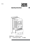
SMVector - Frequency Inverter
Operating Instructions
Contents
1
Safety Information..................................................................................................... 3
2
Technical Data........................................................................................................... 6
2.1
2.2
2.3
3
Installation............................................................................................................... 11
3.1
3.2
4
Dimensions and Mounting....................................................................................................11
3.1.1
NEMA 1 (IP31) Models < 30HP (22kW)................................................................11
3.1.2
NEMA 1 (IP31) Models > 30HP (22kW)................................................................12
3.1.3
NEMA 4X (IP65) Models.......................................................................................13
3.1.4
NEMA 4X (IP65) Models with Disconnect Switch.................................................14
Electrical Installation.............................................................................................................15
3.2.1
Power Connections...............................................................................................15
3.2.1.1 Mains Connection to 120VAC Single-Phase Supply............................15
3.2.1.2 Mains Connection to 240VAC Single-Phase Supply............................16
3.2.1.3 Mains Connection to Three-Phase Supply...........................................16
3.2.1.4 Motor Connection.................................................................................16
3.2.1.5 Installation Recommendations for EMC Compliance...........................17
3.2.1.6 NEMA 4X (IP65) Input Terminal Block..................................................17
3.2.1.7 Dynamic Brake Connections................................................................18
3.2.2
Fuses/Cable Cross-Sections................................................................................19
3.2.3
Control Terminals..................................................................................................20
Commissioning....................................................................................................... 22
4.1
4.2
4.3
4.4
4.5
5
Standards and Application Conditions...................................................................................6
SMV Type Number Designation.............................................................................................7
Ratings....................................................................................................................................8
Local Keypad & Display.......................................................................................................22
Drive Display and Modes of Operation................................................................................24
Parameter Setting.................................................................................................................25
Electronic Programming Module (EPM)...............................................................................25
Parameter Menu...................................................................................................................26
4.5.1
Basic Setup Parameters.......................................................................................26
4.5.2
I/O Setup Parameters...........................................................................................30
4.5.3
Advanced Setup Parameters...............................................................................34
4.5.4
PID Parameters.....................................................................................................38
4.5.5
Vector Parameters................................................................................................40
4.5.6
Network Parameters.............................................................................................42
4.5.7
Diagnostic Parameters.........................................................................................43
4.5.7.1 Terminal & Protection Status Display.......................................................44
4.5.7.2 Keypad Status Display.............................................................................44
4.5.8
Onboard Communications Parameters 15-60HP (11-45kW)...............................45
4.5.9
Sequencer Parameters.........................................................................................46
4.5.9.1 Sequencer Flow Diagram Left..............................................................52
4.5.9.2 Sequencer Flow Diagram Right...........................................................53
4.5.9.3 Sequencer Status.................................................................................54
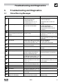
Troubleshooting and Diagnostics......................................................................... 55
5.1
5.2
5.3
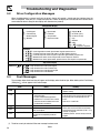
Status/Warning Messages....................................................................................................55
Drive Configuration Messages.............................................................................................56
Fault Messages.....................................................................................................................56
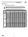
Appendix A........................................................................................................................ 59
A.1
Permissable Cable Lengths..................................................................................................59
SV01L
1
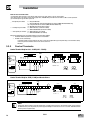
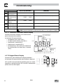
About These Instructions
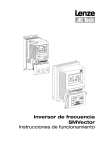
This documentation applies to the SMV frequency inverter and contains important technical data regarding the
installation, operation, and commissioning of the inverter.
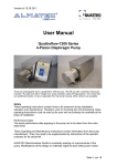
These instructions are only valid for SMV frequency inverters with software revision 4.0 or higher
(refer to drive nameplate, an example is shown below).
Please read these instructions in their entirety before commissioning the drive.
A
B
C
D
INPUT: 3 (3/PE)
400/480 V
2.9/2.5 A
50-60 HZ
OUTPUT: 3 (3/PE)
0 - 400/460 V
2.4/2.1 A
0.75 KW/1HP
0 - 500 HZ
TYPE-4X INDOOR USE ONLY
Type:
ESV751N 0 4TXB
Id-No: 00000000
E F
For detailed information
refer to instruction
Manual: SV01
000000000000000000
ESV751N0 4TXB000XX ## ##
A
B
C
D
E
F
Certifications
Type
Input Ratings
Output Ratings
Hardware Version
Software Version
Scope of delivery
Important
• 1 SMV Inverter
with EPM installed (see Section 4.4)
• 1 Operating Instructions manual
After receipt of the delivery, check immediately whether the items delivered match
the accompanying papers. Lenze AC Tech does not accept any liability for deficiencies
claimed subsequently.
Claim:
• visible transport damage immediately to the forwarder.
• visible deficiencies /incompleteness immediately to your Lenze AC Tech
representative
Copyright © 2006 Lenze AC Tech Corporation
All rights reserved. No part of this manual may be reproduced or transmitted in any form without written permission from Lenze AC Tech
Corporation. The information and technical data in this manual are subject to change without notice. Lenze AC Tech Corporation makes no
warranty of any kind with respect to this material, including, but not limited to, the implied warranties of its merchantability and fitness for a
given purpose. Lenze AC Tech Corporation assumes no responsibility for any errors that may appear in this manual.
All information given in this documentation has been carefully selected and tested for compliance with the hardware and software described.
Nevertheless, discrepancies cannot be ruled out. Lenze AC Tech does not accept any responsibility nor liability for damages that may occur.
Any necessary corrections will be implemented in subsequent editions. This document is printed in the United States
2
SV01L
Safety Information
1
Safety Information
General
Some parts of Lenze AC Tech controllers can be electrically live and some surfaces can be hot. Non-authorized removal
of the required cover, inappropriate use, and incorrect installation or operation creates the risk of severe injury to
personnel and/or damage to equipment.
All operations concerning transport, installation, and commissioning as well as maintenance must be carried out by
qualified, skilled personnel who are familiar with the installation, assembly, commissioning, and operation of variable
frequency drives and the application for which it is being used.
Installation
Ensure proper handling and avoid excessive mechanical stress. Do not bend any components and do not change any
insulation distances during transport, handling, installation or maintenance. Do not touch any electronic components
or contacts. This drive contains electrostatically sensitive components, which can easily be damaged by inappropriate
handling. Static control precautions must be adhered to during installation, testing, servicing and repairing of this drive
and associated options. Component damage may result if proper procedures are not followed.
To ensure proper operation, do not install the drive where it is subjected to adverse environmental conditions such as
combustible, oily, or hazardous vapors; corrosive chemicals; excessive dust, moisture or vibration; direct sunlight or
extreme temperatures.
This drive has been tested by Underwriters Laboratory (UL) and is UL Listed in compliance with the UL508C Safety
Standard. This drive must be installed and configured in accordance with both national and international standards.
Local codes and regulations take precedence over recommendations provided in this and other Lenze AC Tech
documentation.
The SMVector drive is considered a component for integration into a machine or process. It is neither a machine nor
a device ready for use in accordance with European directives (reference machinery directive and electromagnetic
compatibility directive). It is the responsibility of the end user to ensure that the machine meets the applicable
standards.
Electrical Connection
When working on live drive controllers, applicable national safety regulations must be observed. The electrical
installation must be carried out according to the appropriate regulations (e.g. cable cross-sections, fuses, protective
earth [PE] connection). While this document does make recommendations in regards to these items, national and local
codes must be adhered to.
The documentation contains information about installation in compliance with EMC (shielding, grounding, filters and
cables). These notes must also be observed for CE-marked controllers. The manufacturer of the system or machine is
responsible for compliance with the required limit values demanded by EMC legislation.
Application
The drive must not be used as a safety device for machines where there is a risk of personal injury or material damage.
Emergency Stops, over-speed protection, acceleration and deceleration limits, etc must be made by other devices to
ensure operation under all conditions.
The drive does feature many protection devices that work to protect the drive and the driven equipment by generating
a fault and shutting the drive and motor down. Mains power variances can also result in shutdown of the drive. When
the fault condition disappears or is cleared, the drive can be configured to automatically restart, it is the responsibility
of the user, OEM and/or integrator to ensure that the drive is configured for safe operation.
SV01L
3
Safety Information
Explosion Proof Applications
Explosion proof motors that are not rated for inverter use lose their certification when used for variable speed. Due to
the many areas of liability that may be encountered when dealing with these applications, the following statement of
policy applies:
Lenze AC Tech Corporation inverter products are sold with no warranty of fitness for a particular purpose or warranty
of suitability for use with explosion proof motors. Lenze AC Tech Corporation accepts no responsibility for any direct,
incidental or consequential loss, cost or damage that may arise through the use of AC inverter products in these
applications. The purchaser expressly agrees to assume all risk of any loss, cost or damage that may arise from such
application.
Operation
Systems including controllers must be equipped with additional monitoring and protection devices according to the
corresponding standards (e.g. technical equipment, regulations for prevention of accidents, etc.). The controller may be
adapted to your application as described in this documentation.
DANGER!
• After the controller has been disconnected from the supply voltage, live components and power connection
must not be touched immediately, since capacitors could be charged. Please observe the corresponding notes
on the controller.
• Close all protective covers and doors prior to and during operation.
• Do not cycle input power to the controller more than once every two minutes.
• For SMVector models that are equipped with a Disconnect Switch (11th character in model number is L or M),
the Disconnect Switch is intended as a motor service disconnect and does not provide branch circuit protection
to the inverter or motor. When servicing the motor, it is necessary to wait 3 minutes after turning this switch
to the off position before working on motor power wiring as the inverter stores electrical power. To service the
inverter, it is necessary to remove mains ahead of the drive and wait 3 minutes.
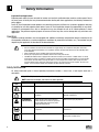
Safety Notifications
All safety information given in these Operating Instructions includes a visual icon, a bold signal word and a
description.
Signal Word! (characterizes the severity of the danger)
NOTE (describes the danger and informs on how to proceed)
Icon
4
Signal Word
Meaning
Consequences if ignored
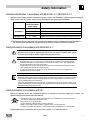
DANGER!
Warns of hazardous electrical voltage.
Death or severe injuries.
WARNING!
Warns of potential, very hazardous
situations.
Risk of severe injury to personnel and/or
damage to equipment.
WARNING!
Hot Surface
Warns of hot surface and risk of burns.
Labels may be on or inside the equipment
to alert people that surfaces may reach
dangerous temperatures.
Risk of severe injury to personnel.
STOP!
Warns of potential damage to material and
equipment.
Damage to the controller/drive or its
environment.
NOTE
Designates a general, useful note.
None. If observed, then using the controller/
drive system is made easier.
SV01L
Safety Information
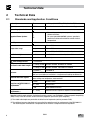
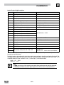
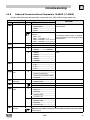
Harmonics Notification in accordance with EN 61000-3-2, EN 61000-3-12:
Operation in public supply networks (Limitation of harmonic currents i.a.w. EN 61000-3-2, Electromagnetic Compatibility
(EMC) Limits). Limits for harmonic current emissions (equipment input current up to 16A/phase).
Directive
Total Power
connected to Mains
(public supply)
Additional Measures Required for Compliance (2)
< 0.5kW
with mains choke
EN 61000-3-2
0.5 ... 1kW
with active filter
> 1kW
complies without additional measures
16 ... 75amp
Additional measures are required for compliance with the standard
EN 61000-3-12
(1) For compliance with EMC regulations, the permissable cable lengths may change.
(2) The additional measures described only ensure that the controller meets the requirements of the EN 61000-3-2.
The machine/system manufacturer is responsible for the machine’s compliance with the regulations.
Safety Information in accordance with EN 61800-5-1:
DANGER! Hazard of Electrical Shock
Capacitors retain charge for approximately 180 seconds after power is removed. Allow at least
3 minutes for discharge of residual charge before touching the drive.
WARNING!
• This product can cause a d.c. current in the PE conductor. Where a residual current-operated (RCD) or
monitoring (RCM) device is used for protection in case of direct or indirect contact, only an RCD or RCM
Type B is allowed on the supply side of this product.
• Leakage Current may exceed 3.5mA AC. The minimum size of the PE conductor shall comply with local
safety regulations for high leakage current equipment.
• In a domestic environment, this product may cause radio interference in which case supplementary
mitigation measures may be required.
NOTE
Control and communications terminals provide reinforced insulation when the drive is connected to a power
system rated up to 300V rms between phase to ground (PE) and the applied voltage on Terminals 16 and 17 is
less than 150VAC between phase and ground.
Control and communications terminals provide basic insulation when the drive is connected to a power system
rated up to 300V between phase to ground (PE) and the applied voltage on terminals 16 and 17 is less than 250
VAC between phase phase and ground (PE).
Safety Information in accordance with UL:
Note for UL approved system with integrated controllers: UL warnings are notes which apply to UL systems. The
documentation contains special information about UL.
Warnings!
•Suitable for use on a circuit capable of delivering not more than 200,000 rms symmetrical amperes, at
the maximum voltage rating marked on the drive.
•Use minimum 75 °C copper wire only.
•Shall be installed in a pollution degree 2 macro-environment.
•NEMA 1 (IP31) models shall be installed in a pollution degree 2 macro-environment.
•All models are suitable for installation in a compartment handling Conditioned Air (i.e., plenum rated).
Torque Requirements (in accordance with UL) are listed in section 3.2.1, Power Connections.
SV01L
5
Technical Data
2
Technical Data
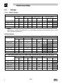
2.1
Standards and Application Conditions
Conformity
CE
Low Voltage (2006/95/EC) & EMC (2004/108/EC) Directives
Approvals
UL508C
Underwriters Laboratories -Power Conversion Equipment
Input voltage phase imbalance
< 2%
−− For central grounded systems, operation is permitted
without restrictions.
−− For corner grounded 400/500V systems, operation is
possible but reinforced insulation to control circuits is
compromised.
Supported Power Systems
TT
TN
Humidity
< 95% non-condensing
Temperature range
Transport
-25 … +70°C
Storage
-20 … +70°C
Operation
-10 … +55°C (with 2.5%/°C current derating above +40°C)
Installation height
0 - 4000m a.m.s.l. (with 5%/1000 m current derating above 1000m a.m.s.l.)
Vibration resistance
acceleration resistant up to 1.0g
Earth leakage current
Max Permissable Cable Length (1)
> 3.5 mA to PE
<= 4.0 Hp (3.0 kW) 30 meters shielded, 60 meters un-shielded
=> 5.0 Hp (3.7 kW) 50 meters shielded, 100 meters un-shielded.
IP31/NEMA 1
Enclosure
Protection measures against
Compliance with EN 61000-3-2
Requirements (2)
IP65/NEMA 4X
NEMA 1 and NEMA 4X model enclosures are plenun rated in accordance with UL
508C and are suitable for installation in a compartment handling conditioned air.
short circuit, earth fault, phase loss, over voltage, under voltage,
motor stalling, over temperature, motor overload
< 0.5kW
with mains choke
0.5 ... 1kW
with active filter
> 1kW
without additional measures
Compliance with EN 61000-3-12
16 ... 75amp
Requirements (2)
Additional measures required for compliance with EN 61000-3-12
Operation in public supply networks (Limitation of harmonic currents i.a.w. EN 61000-3-2, Electromagnetic Compatibility
(EMC) Limits). Limits for harmonic current emissions (equipment input current up to 16A/phase).
(1) The stated cable lengths are permissible at default carrier frequencies (refer to parameter P166).
(2) The additional measures described only ensure that the controller meets the requirements of the EN 61000-3-2.
The machine/system manufacturer is responsible for the machine’s compliance with the regulations.
6
SV01L
Technical Data
2.2
SMV Type Number Designation
The table herein describes the Type numbering designation for the SMVector Inverter models.
ESV
152
N0
2
T
X
B
Electrical Products in the SMVector Series
Power Rating in kW:
251 = 0.25kW (0.33HP)
371 = 0.37kW (0.5HP)
751 = 0.75kW (1HP)
112 = 1.1kW (1.5HP)
152 = 1.5kW (2HP)
222 = 2.2kW (3HP)
302 = 3.0kW (4HP)
402 = 4.0kW (5HP)
113 = 11.0kW (15HP)
153 = 15.0kW (20HP)
183 = 18.5kW (25HP)
223 = 22.0kW (30HP)
303 = 30.0kW (40HP)
373 = 37.5kW (50HP)
453 = 45.0kW (60HP)
552 = 5.5kW (7.5HP)
752 = 7.5kW (10HP)
Installed I/O & Communication Module(s):
C_ = CANopen (Available all models)
D_ = DeviceNet (Available all models)
E_ = Ethernet/IP, ModBus TCP/IP (Avail all models)
R_ = RS-485 / ModBus /Lecom (Avail all models)
P_ = ProfiBus-DP (Available all models)
N_ = No Communications installed
The “_” blank can be:
0 = Standard Keypad
Input Voltage:
1 = 120 VAC (doubler output) or 240 VAC
2 = 240 VAC
4 = 400/480 VAC
6 = 600 VAC
Input Phase:
S = Single Phase Input only
Y = Single or Three Phase Input
T = Three Phase Input only
Input Line Filter
F = Integral EMC Filter
L = Integral EMC Filter and Integrated Disconnect Switch (NEMA 4X/IP65 Models only)
M = Integrated Disconnect Switch (NEMA 4X/IP65 Models only)
X = No EMC Filter/ No Disconnect Switch
Enclosure:
B = NEMA 1/IP31; Indoor only
C = NEMA 4X/IP65; Indoor only; Convection cooled
D = NEMA 4X/IP65; Indoor only; Fan cooled
E = NEMA 4X/IP65; Indoor/Outdoor; Convection cooled
F = NEMA 4X/IP65; Indoor/Outdoor; Fan cooled
NOTE
Prior to installation make sure the enclosure is suitable for the end-use environment
Variables that influence enclosure suitability include (but are not limited to) temperature, airborne
contaminates, chemical concentration, mechanical stress and duration of exposure (sunlight,
wind, precipitation).
SV01L
7
Technical Data
2.3
Ratings
120V / 240VAC Models
Mains = 120V Single Phase (1/N/PE) (90...132V), 240V Single Phase (2/PE) (170...264V); 48...62Hz
Type
Power
Mains Current
Output Current
Heat Loss (Watts)
Hp
kW
120V
A
240V
A
Cont (In)
A
Max I
%
N1/IP31
N4X/IP65 N4X/IP65
No filter
W/ filter
ESV251--1S--
0.33
0.25
6.8
3.4
1.7
200
24
ESV371--1S--
0.5
0.37
9.2
4.6
2.4
200
32
32
ESV751--1S--
1
0.75
16.6
8.3
4.2
200
52
41
ESV112--1S--
1.5
1.1
20
10.0
6.0
200
74
74
NOTES:
Output Current: The Output Current Maximum (%) is a percentage of the Output Current Continuous Amps (In) rating
and is adjustable in parameter P171.
240VAC Models
Mains = 240V Single Phase (2/PE) (170...264V); 48...62Hz
Type
Power
Mains Current
Output Current
Heat Loss (Watts)
Cont (In)
A
Max I
%
N1/IP31
20
N4X/IP65 N4X/IP65
No filter
W/ filter
Hp
kW
240V
A
ESV251--2S--
0.33
0.25
3.4
1.7
200
ESV371--2S--
0.5
0.37
5.1
2.4
200
30
ESV751--2S--
1
0.75
8.8
4.2
200
42
ESV112--2S--
1.5
1.1
12.0
6.0
200
63
ESV152--2S--
2
1.5
13.3
7.0
200
73
ESV222--2S--
3
2.2
17.1
9.6
200
97
240V Single Phase (2/PE) (170...264V), 240V Three Phase (3/PE) (170...264V); 48...62Hz
Type
8
Power
Mains Current
Output Current
Heat Loss (Watts)
Hp
kW
A
A
Cont (In)
A
ESV371--2Y--
0.5
0.37
5.1
2.9
2.4
200
27
26
ESV751--2Y--
1
0.75
8.8
5.0
4.2
200
41
38
ESV112--2Y--
1.5
1.1
12.0
6.9
6.0
200
64
59
ESV152--2Y--
2
1.5
13.3
8.1
7.0
200
75
69
ESV222--2Y--
3
2.2
17.1
10.8
9.6
200
103
93
1~ (2/PE)
3~ (3/PE)
SV01L
Max I
%
N1/IP31
N4X/IP65 N4X/IP65
No filter
W/ filter
Technical Data
240V Three Phase (3/PE) (170...264V); 48...62Hz
Type
Power
Mains Current
Output Current
Heat Loss (Watts)
Cont (In)
A
Max I
%
N1/IP31
64
Hp
kW
240V
A
ESV112--2T--
1.5
1.1
6.9
6
200
ESV152--2T--
2
1.5
8.1
7
200
75
ESV222--2T--
3
2.2
10.8
9.6
200
103
N4X/IP65 N4X/IP65
No filter
W/ filter
ESV402--2T--
5
4.0
18.6
16.5
200
154
139
ESV552--2T--
7.5
5.5
26
23
200
225
167
ESV752--2T--
10
7.5
33
29
200
274
242
ESV113--2T--
15
11
48
42
180
485
468
ESV153--2T--
20
15
59
54
180
614
591
NOTES:
Output Current: The Output Current Maximum (%) is a percentage of the Output Current Continuous Amps (In) rating
and is adjustable in parameter P171.
400...480VAC Models
400 ... 480V Three Phase (3/PE) (400V: 340...440V), (480V: 340...528V); 48...62Hz
Type
Power
Mains Current
480V
A
Output Current
Cont (In)
A
Heat Loss (Watts)
Hp
kW
400V
A
400V
480V
400V
480V
ESV371--4T--
0.5
0.37
1.7
1.5
1.3
1.1
175
200
23
21
25
ESV751--4T--
1
0.75
2.9
2.5
2.4
2.1
175
200
37
33
37
ESV112--4T--
1.5
1.1
4.2
3.6
3.5
3.0
175
200
48
42
46
ESV152--4T--
2
1.5
4.7
4.1
4.0
3.5
175
200
57
50
54
ESV222--4T--
3
2.2
6.1
5.4
5.5
4.8
175
200
87
78
82
ESV302--4T--
4
3.0
8.3
7.0
7.6
6.3
175
200
ESV402--4T--
5
4.0
10.6
9.3
9.4
8.2
175
200
128
103
111
ESV552--4T--
7.5
5.5
14.2
12.4
12.6 11.0 175
200
178
157
165
ESV752--4T--
10
7.5
18.1
15.8
16.1 14.0 175
200
208
190
198
ESV113--4T--
15
11
27
24
24
21
155
180
418
388
398
ESV153--4T--
20
15
35
31
31
27
155
180
493
449
459
ESV183--4T--
25
18.5
44
38
39
34
155
180
645
589
600
ESV223--4T--
30
22
52
45
46
40
155
180
709
637
647
ESV303--4T--
40
30
68
59
60
52
155
180
1020
ESV373--4T--
50
37.5
85
74
75
65
155
180
1275
ESV453--4T--
60
45
100
87
88
77
155
180
1530
Max I
%
N1/IP31
N4X/IP65 N4X/IP65
No filter
W/ filter
95
NOTES:
Output Current: The Output Current Maximum (%) is a percentage of the Output Current Continuous Amps (In) rating
and is adjustable in parameter P171.
For 400...480 VAC models, the output current maximum (%) in the 400V column is used when P107 = 0
For 400...480 VAC models, the output current maximum (%) in the 480V column is used when P107 = 1
SV01L
9
Technical Data
600VAC Models
600V Three Phase (3/PE) (425...660V); 48...62Hz
Type
Power
Mains Current
Output Current
Heat Loss (Watts)
Max I
%
N1/IP31
A
Cont (In)
A
N4X/IP65 N4X/IP65
No filter
W/ filter
Hp
kW
ESV751--6T--
1
0.75
2
1.7
200
37
31
ESV152--6T--
2
1.5
3.2
2.7
200
51
43
ESV222--6T--
3
2.2
4.4
3.9
200
68
57
ESV402--6T--
5
4
6.8
6.1
200
101
67
ESV552--6T--
7.5
5.5
10.2
9
200
148
116
ESV752--6T--
10
7.5
12.4
11
200
172
152
ESV113--6T--
15
11
19.7
17
180
380
356
ESV153--6T--
20
15
25
22
180
463
431
ESV183--6T--
25
18.5
31
27
180
560
519
ESV223--6T--
30
22
36
32
180
640
592
ESV303--6T--
40
30
47
41
180
930
ESV373--6T--
50
37.5
59
52
180
1163
ESV453--6T--
60
45
71
62
180
1395
NOTES:
Output Current: The Output Current Maximum (%) is a percentage of the Output Current Continuous Amps (In) rating
and is adjustable in parameter P171.
STOP!
• For installations above 1000m a.m.s.l., derate In by 5% per 1000m, do not
exceed 4000m a.m.s.l.
• Operation above 40°C, derate In by 2.5% per °C, do not exceed 55°C.
Output Current (In) derating for Carrier Frequency (P166) for NEMA 1 (IP31) Models:
- If P166=2 (8 kHz), derate In to 92% of drive rating
- If P166=3 (10 kHz), derate In to 84% of drive rating
Output Current (In) derating for Carrier Frequency (P166) for NEMA 4X (IP65) Models:
- If P166=1 (6 kHz), derate In to 92% of drive rating
- If P166=2 (8 kHz), derate In to 84% of drive rating
- If P166=3 (10 kHz), derate In to 76% of drive rating
10
SV01L
Installation
3
Installation
3.1
Dimensions and Mounting
WARNING!
Drives must not be installed where subjected to adverse environmental conditions such as: combustible, oily, or
hazardous vapors; corrosive chemicals; excessive dust, moisture or vibration; direct sunlight or extreme temperatures.
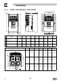
3.1.1
NEMA 1 (IP31) Models < 30HP (22kW)
b2
s2
c
Mounting Screws
4 x #10
18 lb-in
4 x M5
20 Nm
(
)
b1
b
s1
a1
s1
s2
a
Type
a
in (mm)
a1
in (mm)
b
in (mm)
b1
in (mm)
b2
in (mm)
c
in (mm)
s1
in (mm)
s2
in (mm)
m
lb (kg)
ESV251~~~~~B; ESV371~~~~~B
ESV751~~~~~B
3.90 (99)
3.12 (79)
7.48 (190)
7.00 (178)
0.24 (6)
4.35 (111)
0.6 (15)
2.0 (50)
2.0 (0.9)
ESV112~~~~~B; ESV152~~~~~B
G2
ESV222~~~~~B
3.90 (99)
3.12 (79)
7.52 (191)
7.00 (178)
0.26 (7)
5.45 (138)
0.6 (15)
2.0 (50)
2.8 (1.3)
G3 ESV402~~~~~B
3.90 (99)
3.12 (79)
7.52 (191)
7.00 (178)
0.30 (8)
5.80 (147)
0.6 (15)
2.0 (50)
3.2 (1.5)
H1 ESV552~~~~~B; ESV752~~~~~B 5.12 (130)
4.25 (108)
9.83 (250)
9.30 (236)
0.26 (7)
6.30 (160)
0.6 (15)
2.0 (50)
6.0 (2.0)
ESV113~~~~~B; ESV153~~~~~B
6.92 (176)
ESV183~~~~~B; ESV223~~~~~B
5.75 (146)
12.50 (318)
11.88 (302)
0.31 (8)
8.09 (205)
0.6 (15)
2.0 (50)
13.55 (6.15)
Type
N
in (mm)
P
in (mm)
P1
in (mm)
Q
in (mm)
S
in (mm)
G1
1.84 (47)
1.93 (49)
.70 (18)
1.00 (25)
.88 (22)
G2
1.84 (47)
3.03 (77)
.70 (18)
1.00 (25)
.88 (22)
G3
1.84 (47)
3.38 (86)
.70 (18)
1.00 (25)
G1
J1
Conduit Hole Dimensions
Q
P1
Q
S
H1
P
J1
2.46 (62)
3.32 (84)
N
SV01L
3.55 (90)
4.62 (117)
.13 (3)
.73 (19)
1.38 (35)
1.40 (36)
.88 (22)
1.13 (29)
.88 (22)
1.31 (33)
.88 (22)
11
Installation
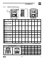
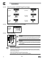
3.1.2
NEMA 1 (IP31) Models > 30HP (22kW)
c
b2
b1
s2
b
s1
s1
SMV
SMV
s2
a1
a
Type
a
in (mm)
a1
in (mm)
b
in (mm)
b1
in (mm)
b2
in (mm)
c
in (mm)
s1
in (mm)
s2
in (mm)
m
lb (kg)
K1
ESV303~~4~~B;
ESV303~~6~~B
8.72 (221)
7.50 (190)
14.19 (360)
13.30 (338)
0.45 (11.4)
10.07 (256)
0.6 (15)
2.0 (50)
24 (10.9)
K2
ESV373~~4~~B;
ESV373~~6~~B
8.72 (221)
7.50 (190)
17.19 (436)
16.30 (414)
0.45 (11.4)
10.07 (256)
0.6 (15)
2.0 (50)
31 (14.1)
K3
ESV453~~4~~B
ESV453~~6~~b
8.72 (221)
7.50 (190)
20.19 (513)
19.30 (490)
0.45 (11.4)
10.07 (256)
0.6 (15)
2.0 (50)
35 (15.9)
Conduit Hole Dimensions
Type
N
in (mm)
P
in (mm)
P1
in (mm)
Q
in (mm)
S
in (mm)
S1
in (mm)
K1
3.75 (95)
5.42 (137)
1.50 (38.1)
1.75 (44.4)
1.75 (44.4)
0.875 (22.2)
K2
3.75 (95)
5.42 (137)
1.50 (38.1)
1.75 (44.4)
1.75 (44.4)
0.875 (22.2)
K3
3.75 (95)
5.42 (137)
1.50 (38.1)
1.75 (44.4)
1.75 (44.4)
0.875 (22.2)
S1
S
P1
C
P
Q
N
12
Q
N
SV01L
Installation
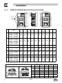
3.1.3
NEMA 4X (IP65) Models
b2
c
s2
Mounting Screws
4 x #8 32
10 lb in
4 x M4
1 2 Nm
(
)
b1
b
s1
s1
s2
a1
a
Type
a
in (mm)
a1
in (mm)
b
in (mm)
b1
in (mm)
b2
in (mm)
c
in (mm)
s1
in (mm)
s2
in (mm)
m
lb (kg)
ESV371N01SX_; ESV751N01SX_;
ESV371N02YX_; ESV751N02YX_;
ESV371N04TX_; ESV751N04TX_;
ESV751N06TX_; ESV371N02SF_;
ESV751N02SF_; ESV371N04TF_;
ESV751N04TF_;
6.28 (160)
5.90 (150)
8.00 (203)
6.56 (167)
0.66 (17)
4.47 (114)
2.00 (51)
2.00 (51)
3.6 (1.63)
ESV112N01SX_; ESV112N02YX_;
ESV152N02YX_; ESV112N04TX_;
ESV152N04TX_; ESV222N04TX_;
R2 ESV152N06TX_; ESV222N06TX_;
ESV112N02SF_; ESV152N02SF_;
ESV112N04TF_; ESV152N04TF_;
ESV222N04TF_; ESV302N04TF_;
6.28 (160)
5.90 (150)
8.00 (203)
6.56 (167)
0.66 (17)
6.31 (160)
2.00 (51)
2.00 (51)
5.9 (2.68)
S1 ESV222N02YX_; ESV222N02SF_
7.12 (181)
6.74 (171)
8.00 (203)
6.56 (167)
0.66 (17)
6.77 (172)
2.00 (51)
2.00 (51)
7.1 (3.24)
ESV552N02TX~; ESV752N02TX~
T1 ESV752N04TX~; ESV752N06TX~;
ESV752N04TF~
8.04 (204)
7.56 (192)
10.00 (254)
8.04 (204)
0.92 (23)
8.00 (203)
4.00 (102)
4.00 (102)
10.98 (4.98)
ESV402N02TX_; ESV402N04TX_;
ESV552N04TX_; ESV402N06TX_
V1
ESV552N06TX_; ESV402N04TF_;
ESV552N04TF_
8.96 (228)
8.48 (215)
10.00 (254)
8.04 (204)
0.92 (23)
8.00 (203)
4.00 (102)
4.00 (102)
11.58 (5.25)
W1
ESV113N02TX~; ESV153N02TX~
ESV113N04TX~; ESV153N04TX~
ESV113N04TF~; ESV153N04TF~
ESV113N06TX~; ESV153N06TX~
ESV183N04TX~; ESV183N04TF~
ESV183N06TX~
9.42 (240)
8.94 (228)
14.50 (368)
12.54 (319)
0.92 (24)
9.45 (241)
4.00 (102)
4.00 (102)
22.0 (10.0)
X1
ESV223N04TX~; ESV223N04TF~
ESV223N06TX~
9.42 (240)
8.94 (228)
18.5 (470)
16.54 (420)
0.92 (24)
9.45 (241)
4.00 (102)
4.00 (102)
25.5 (11.6)
R1
_ = Last digit of part number:
C = N4X Indoor (convection cooled)
~ = Last digit of part number: D = N4X Indoor (fan cooled)
E = N4X In/Outdoor (convection cooled)
F = N4X In/Outdoor (fan cooled)
Conduit Hole Dimensions
Q
Type
Q
Q
Q
S
S
P
S1
P
N
N
N
in (mm)
P
in (mm)
Q
in (mm)
S
in (mm)
S1
in (mm)
R1
3.14 (80)
2.33 (59)
1.50 (38)
.88 (22)
n/a
R2
3.14 (80)
4.18 (106)
1.50 (38)
.88 (22)
n/a
S1
3.56 (90)
4.63 (118)
1.50 (38)
.88 (22)
n/a
T1
4.02 (102)
5.00 (127)
1.85 (47)
1.06 (27)
n/a
V1
4.48 (114)
5.00 (127)
1.85 (47)
1.06 (27)
n/a
W1
4.71 (120)
5.70 (145)
2.00 (51)
1.375 (35)
1.125 (28)
X1
4.71 (120)
5.70 (145)
2.00 (51)
1.375 (35)
1.125 (28)
SV01L
13
Installation
3.1.4
NEMA 4X (IP65) Models with Disconnect Switch
b2
c1
c
s2
Mounting Screws
4 x #8 32
10 lb in
4 x M4
1 2 Nm
(
)
b1
s1
s1
b
s2
a1
a
a
in
(mm)
a1
in
(mm)
b
in
(mm)
b1
in
(mm)
b2
in
(mm)
c
in
(mm)
c1
in
(mm)
s1
in
(mm)
s2
in
(mm)
m
lb
(kg)
6.28
(160)
5.90
(150)
10.99
(279)
9.54
(242)
0.66
(17)
4.47
(114)
.86
(22)
2.00
(51)
2.00
(51)
4.7
(2.13)
6.28
(160)
5.90
(150)
10.99
(279)
9.54
(242)
0.66
(17)
6.31
(160)
.86
(22)
2.00
(51)
2.00
(51)
7.9
(3.58)
AD1 ESV222N02SL_; ESV222N02YM_;
7.12
(181)
6.74
(171)
10.99
(279)
9.54
(242)
0.66
(17)
6.77
(172)
.86
(22)
2.00
(51)
2.00
(51)
9.0
(4.08)
ESV552N02TM~; ESV752N02TM~
AB1 ESV752N04TM~; ESV752N06TM~;
ESV752N04TL~
8.04
(204)
7.56
(192)
13.00
(330)
11.04
(280)
0.92
(23)
8.00
(203)
.86
(22)
4.00
(102)
4.00
(102)
13.9
(6.32)
AC1
ESV402N02TM_; ESV402N04TM_;
ESV552N04TM_; ESV402N06TM_;
ESV552N06TM_; ESV402N04TL_;
ESV552N04TL_
8.96
(228)
8.48
(215)
13.00
(330)
11.04
(280)
0.92
(23)
8.04
204)
.86
(22)
4.00
(102)
4.00
(102)
14.7
(6.66)
AE1
ESV113N04TM~; ESV153N04TM~,
ESV113N06TM~; ESV153N06TM~
9.42
(240)
8.94
(228)
14.50
(368)
12.54
(319)
0.92
(24)
9.45
(241)
0.73
(19)
4.00
(102)
4.00
(102)
23.0
(10.4)
ESV113N02TM~; ESV153N02TM~
ESV113N04TL~; ESV153N04TL~
AF1 ESV183N04TL~; ESV223N04TL~
ESV183N04TM~; ESV223N04TM~
ESV183N06TM~; ESV223N06TM~
9.42
(240)
8.94
(228)
18.5
(470)
16.54
(420)
0.92
(24)
9.45
(241)
0.73
(19)
4.00
(102)
4.00
(102)
28.5
(12.9)
Type
ESV371N01SM_; ESV371N02YM_;
ESV371N02SL_; ESV371N04TM_;
ESV371N04TL_; ESV371N06TM_;
AA1
ESV751N01SM_; ESV751N02YM_;
ESV751N02SL_; ESV751N04TM_;
ESV751N04TL_; ESV751N06TM_;
ESV112N01SM_; ESV112N02YM_;
ESV112N02SL_; ESV112N04TM_;
ESV112N04TL_; ESV152N02YM_;
AA2 ESV152N02SL_; ESV152N04TM_;
ESV152N04TL_; ESV152N06TM_;
ESV222N04TM_; ESV222N04TL_;
ESV222N06TM_; ESV302N04TL_;
_ = Last digit of part number:
C = N4X Indoor (convection cooled)
Conduit Hole Dimensions
Q
Q
Q
~ = Last digit of part number: D = N4X Indoor (fan cooled)
Type
N
in (mm)
AA1
3.14 (80)
2.33 (59)
1.50 (38)
.88 (22)
n/a
AA2
3.14 (80)
4.18 (106)
1.50 (38)
.88 (22)
n/a
Q
S
S
P
N
14
S1
P
N
SV01L
P
in (mm)
Q
in (mm)
S
in (mm)
S1
in (mm)
AD1
3.56 (90)
4.63 (118)
1.50 (38)
.88 (22)
n/a
AB1
4.02 (102)
5.00 (127)
1.85 (47)
1.06 (27)
n/a
AC1
4.48 (114)
5.00 (127)
1.85 (47)
1.06 (27)
n/a
AE1
4.71 (120)
5.70 (145)
2.00 (51)
1.375 (35)
1.125 (28)
AF1
4.71 (120)
5.70 (145)
2.00 (51)
1.375 (35)
1.125 (28)
Installation
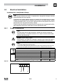
3.2
Electrical Installation
Installation After a Long Period of Storage
STOP!
Severe damage to the drive can result if it is operated after a long period of storage or inactivity
without reforming the DC bus capacitors.
If input power has not been applied to the drive for a period of time exceeding three years (due to
storage, etc), the electrolytic DC bus capacitors within the drive can change internally, resulting
in excessive leakage current. This can result in premature failure of the capacitors if the drive is
operated after such a long period of inactivity or storage.
In order to reform the capacitors and prepare the drive for operation after a long period of inactivity,
apply input power to the drive for 8 hours prior to actually operating the motor.
3.2.1
Power Connections
STOP!
If the kVA rating of the AC supply transformer is greater than 10 times the input kVA
rating of the drive(s), an isolation transformer or 2-3% input line reactor must be added
to the line side of the drive(s).
DANGER! Hazard of electrical shock!
Circuit potentials up to 600 VAC are possible. Capacitors retain charge after power is
removed. Disconnect power and wait at least three minutes before servicing the drive.
STOP!
• Verify mains voltage before connecting to drive.
• Do not connect mains power to the output terminals (U,V,W)! Severe damage to the drive will result.
• Do not cycle mains power more than once every two minutes. Damage to the drive may result.
Mains and Motor Terminations
Type
Torque
Strip Length
<5HP
12 lb-in (1.3 Nm)
0.25 in (6mm)
ESV552xx2T, ESV752xx2T, ESV113xx4/6, ESV153xx4/6, ESV183xx6, ESV223xx6
16 lb-in (1.8 Nm)
0.25 in (6mm)
ESV552xx4Txx, ESV752xx4Txx, ESV552xx6Txx, ESV752xx6Txx
12 lb-in (1.3Nm)
0.25 in (6mm)
ESV113xx2xxx, ESV153xx2xxx, ESV183xx4xxx, ESV223xx4xxx
24 lb-in (2.7 Nm)
0.25 in (6mm)
6-7 lb-in (0.67-0.79 Nm)
0.25 in (6mm)
Torque: N4X/IP65 Door Screws
N4X/IP65
3.2.1.1
Mains Connection to 120VAC Single-Phase Supply
ESV...N01S...
PE L1 L2 N
PE
L1
N
SV01L
15
Installation
3.2.1.2
Mains Connection to 240VAC Single-Phase Supply
PE L1 L2 N
PE L1 L2 N
ESV...N01S...
ESV...N01S...
PE
L1
L2
PE
PE L1 L2 L3
ESV...N02Y...
(1/N/PE AC)
PE
L1
L2
PE
PE L1 L2
L1
N
PE L1 L2
ESV...N02S...
(2/PE AC)
ESV...N02S...
(1/N/PE AC)
PE
L1
L2
PE
L1
N
Mains Connection to Three-Phase Supply
ESV...N02Y...
ESV...N02T...
ESV...N04T...
ESV...N06T...
(3/PE AC)
PE L1 L2 L3
PE
3.2.1.4
N
PE L1 L2 L3
ESV...N02Y...
(2/PE AC)
3.2.1.3
L1
L1
L2
L3
Motor Connection
U/T1 V/T2 W/T3 PE
WARNING!
PES
PES
PE
PES
If the cable connection between the drive and the motor has an in-line contactor or
circuit breaker then the drive must be stopped prior to opening/closing the contacts.
Failure to do so may result in 0vercurrent trips and/or damage to the inverter.
PES
PES
WARNING!
M
3~
PE
Leakage current may exceed 3.5 mA AC. The minimum size of the protective
earth (PE) conductor shall comply with local safety regulations for high leakage
current equipment.
PES = Protective Earth Shielding
STOP!
In the case of a Spinning Motor:
To bring free-wheeling loads such as fans to a rest before starting the drive, use the DC injection
braking function. Starting a drive into a freewheeling motor creates a direct short-circuit and may
result in damage to the drive.
Confirm motor suitability for use with DC injection braking.
Consult parameter P110 for starting / restarting into spinning motors.
16
SV01L
Installation
3.2.1.5
Installation Recommendations for EMC Compliance
For compliance with EN 61800-3 or other EMC standards, motor cables, line cables and control or communications
cables must be shielded with each shield/screen clamped to the drive chassis. This clamp is typically located at the
conduit mounting plate.
The EMC requirements apply to the final installation in its entirety, not to the individual components used. Because
every installation is different, the recommended installation should follow these guidelines as a minimum. Additional
equipment (such as ferrite core absorbers on power conductors) or alternative practices may be required to meet
conformance in some installations.
Motor cable should be low
capacitance (core/core <75pF/m,
core/shield <150pF/m). Filtered
drives can meet the class A limits
of EN 55011 and EN 61800-3
Category 2 with this type of motor
cable up to 10 meters.
NOTE: Refer to Appendix A for
recommended cable lengths. Any
external line filter should have its
chassis connected to the drive
chassis by mounting hardware
or with the shortest possible wire
or braid.
3.2.1.6
Enclosure / Backplate
External
Control
Circuits
Control and signal cabling
should be separated from
power cables by
a minimum of 300mm
From
AC Supply
360° shield termination to
backplate using saddle clamp
Screened motor cable
core/core <75pF/M
core/shield <150pF/M
From
Motor
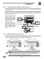
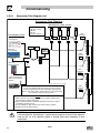
NEMA 4X (IP65) Input Terminal Block
For NEMA 4X (IP65) models with integrated EMC filter and/or integrated line disconnect, the input terminal block is
located on the right-hand side of the SMV inverter in the NEMA 4 X (IP65) enclosure. The single and three phase models
are illustrated herein. Refer to paragraph 3.2.3 Control Terminals for pin out information.
L1
L1
L2
U
V
W
PE
U
L2
Single Phase (2/PE)
With Filter and/or integrated line disconnect
V
W
PE
L3
Three Phase (3/PE)
With Filter and/or integrated line disconnect
WARNING
Power remains present for up to 3 minutes on power input terminals (L1, L2 and L3) and output
terminals (U, V and W) even when the disconnect switch is in the OFF position. Remove input power
ahead of the drive and wait 3 minutes before removing the terminal cover.
SV01L
17
Installation
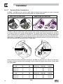
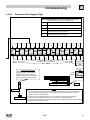
3.2.1.7
Dynamic Brake Connections
For NEMA 1 and NEMA 4X Drives rated up to 30HP (22kW) the Dynamic Brake connections are made as illustrated
herein. Refer to the SMV Dynamic Brake Instructions (DBV01) for complete information.
NEMA 1 (IP31) up to 30HP (22kW)
NEMA 4X (IP65) up to 30HP (22kW)
+
-
The SMV 40...60Hp (30...45kW) models include a dynamic brake transistor as standard and only require the connection
of an external resistor kit for dynamic braking operation. The dynamic brake resistor connections for 40...60 Hp
(30.0...45.0 kW) drives are standard built-in connections as illustrated in the diagram below. In the 40Hp (30kW) model
drives, the dynamic brake connector is on the right-hand side of the drive and the terminals from top to bottom are B-,
BRAKE and B+. In the 50/60HP (37.5/45 kW) model drives, the dynamic brake connector is on the left-hand side of the
drive and the terminals from top to bottom are B+, BRAKE and B-.
B
BRAKE
B+
B+
BRAKE
B
50/60HP
40HP
External resistor kits must be connected to terminals B+ and BRAKE (no connection to B-). Refer to the table herein
for external resistor kit selection. Refer to parameter P189 for enabling the dynamic brake function in the 40...60Hp
(30...45kW) models.
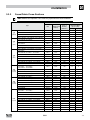
Type
18
400/480 VAC SMV Inverter
Hp
kW
Resistance (W)
Resistor Kit
Power (W)
Catalog #
ESV303**4T**
40
30
23.5
1020
841-013
ESV373**4T**
50
37
17
1400
841-015
841-015
Catalog #
ESV453**4T**
60
600 VAC SMV Inverter
Type
Hp
45
17
kW
Resistance (W)
1400
Resistor Kit
Power (W)
ESV303**6T**
40
30
35
1070
841-014
ESV373**6T**
50
37
24
1560
841-016
ESV453**6T**
60
45
24
1560
841-016
SV01L
Installation
3.2.2
Fuses/Cable Cross-Sections
NOTE: Observe local regulations. Local codes may supersede these recommendations
Recommendations
120V
1~
(1/N/PE)
240V
1~
(2/PE)
240V
3~
(3/PE)
400V
or 480V
3~(3/PE)
400V
or 480V
3~(3/PE)
600V
3~(3/PE)
Input Power Wiring
(L1, L2, L3, PE)
Fuse
Miniature circuit
breaker(1)
Fuse (2) or
Breaker(3)
(N. America)
ESV251N01SXB
M10 A
C10 A
10 A
1.5
14
ESV371N01SXB, ESV371N01SX*
M16 A
C16 A
15 A
2.5
14
10
Type
[mm²]
[AWG]
ESV751N01SXB, ESV751N01SX*
M25 A
C25 A
25 A
4
ESV112N01SXB, ESV112N01SX*
ESV251N01SXB, ESV251N02SXB, ESV371N01SXB,
ESV371N02YXB, ESV371N02SF*
ESV751N01SXB, ESV751N02YXB, ESV751N02SF*
ESV112N02YXB, ESV112N02SFC, ESV112N01SXB
ESV112N01SX*
ESV152N02YXB, ESV152N02SF*
M32 A
C32 A
30A
4
10
M10 A
C10 A
10 A
1.5
14
ESV222N02YXB, ESV222N02SF*
ESV371N02YXB, ESV751N02YXB, ESV371N02Y_*,
ESV751N02Y_*
ESV112N02YXB, ESV152N02YXB, ESV112N02TXB,
ESV152N02TXB, ESV112N02Y *, ESV152N02Y *
ESV222N02YXB, ESV222N02TXB, ESV222N02YX*
M16 A
C16 A
15 A
2.5
14
M20 A
C20 A
20 A
2.5
12
12
M25 A
C25 A
25 A
2.5
M32 A
C32A
30 A
4
10
M10 A
C10 A
10 A
1.5
14
M16 A
C16 A
12 A
1.5
14
M20 A
C20 A
20 A
2.5
12
10
ESV402N02TXB, ESV402N02T_*
M32 A
C32 A
30 A
4.0
ESV552N02TXB, ESV552N02T_~
M40 A
C40 A
35 A
6.0
8
ESV752N02TXB, ESV752N02T_~
M50 A
C50 A
45 A
10
8
ESV113N02TXB, ESV113N02TX~, ESV113N02TM~
M80 A
C80 A
80 A
16
6
ESV153N02TXB, ESV153N02TX~, ESV153N02TM~
ESV371N04TXB ...ESV222N04TXB
ESV371N04T_* ...ESV222N04T_*
ESV371N04TF* ...ESV222N04TF*
ESV302N04T_*
M100 A
C100 A
90 A
16
4
M10 A
C10 A
10 A
1.5
14
M16 A
C16 A
15 A
2.5
14
ESV402N04TXB, ESV402N04T_*
M16 A
C16 A
20 A
2.5
14
ESV552N04TXB, ESV552N04T_*
M20 A
C20 A
20 A
2.5
14
10
ESV752N04TXB, ESV752N04T_~
M25 A
C25 A
25 A
4.0
ESV113N04TXB, ESV113N04T_~
M40 A
C40 A
40 A
4
8
ESV153N04TXB, ESV153N04T_~
M50 A
C50 A
50 A
10
8
ESV183N04TXB, ESV183N04T_~
M63 A
C63A
70 A
10
6
ESV223N04TXB, ESV223N04T_~
M80 A
C80 A
80 A
16
6
ESV303N04TXB
M100 A
C100 A
100 A
25
4
ESV373N04TXB
M125 A
C125 A
125 A
35
2
ESV453N04TXB
ESV751N06TXB ...ESV222N06TXB
ESV751N06T * ...ESV222N06T *
ESV402N06TXB, ESV402N06T_*
M160 A
C160 A
150 A
35
1
M10 A
C10 A
10 A
1.5
14
M16 A
C16 A
12 A
1.5
14
ESV552N06TXB, ESV552N06T_*
M16 A
C16 A
15 A
2.5
14
ESV752N06TXB, ESV752N06T_~
M20 A
C20 A
20 A
2.5
12
ESV113N06TXB, ESV113N06TX~, ESV113N06TM~
M32 A
C32 A
30 A
4
10
ESV153N06TXB, ESV153N06TX~, ESV153N06TM~
M40 A
C40 A
40 A
4
8
ESV183N06TXB, ESV183N06TX~, ESV183N06TM~
M50 A
C50 A
50 A
6
8
ESV223N06TXB, ESV223N06TX~, ESV223N06TM~
M63 A
C63 A
60 A
10
8
ESV303N06TXB
M80 A
C80 A
70 A
16
6
ESV373N06TXB
M100 A
C100 A
90 A
16
4
ESV453N06TXB
M125 A
C125 A
110 A
25
2
SV01L
19
Installation
Notes for Fuse and Cable Table:
(1) Installations with high fault current due to large supply mains may require a type D circuit breaker.
(2) UL Class CC or T fast-acting current-limiting type fuses, 200,000 AIC, preferred. Bussman KTK-R, JJN or JJS or equivalent.
(3) Thermomagnetic type breakers preferred.
_ 11th digit of part number:
* = Last digit of part number:
~ = Last digit of part number:
F = Integral EMC Filter
L = Integral EMC Filter and Integrated Disconnect Switch (NEMA 4X/IP65 Models only)
M = Integrated Disconnect Switch (NEMA 4X/IP65 Models only)
X = No EMC Filter/ No Disconnect Switch
C = N4X Indoor only (convection cooled)
E = N4X Indoor/Outdoor (convection cooled)
D = N4X Indoor only (fan cooled)
F = N4X Indoor/Outdoor (fan cooled)
Observe the following when using Ground Fault Circuit Interrupters (GFCIs):
• Installation of GFCI only between supplying mains and controller.
• The GFCI can be activated by:
- capacitive leakage currents between the cable screens during operation (especially with long, screened motor cables)
- connecting several controllers to the mains at the same time
- RFI filters
3.2.3
Control Terminals
Control Terminal Strip for 0.33 - 10 HP (0.25 - 7.5 kW):
ALsw
COM
1 2
4
13A 13B 13C
1 2
4
AOUT
DIGOUT
2k … 10k
AWG 26…16
(<1mm²)
13A 13B 13C
COM
PNP
1 2 5 6 25 4 11 13A 13B 13C 14 30 16 17
0.25 in (6 mm)
ALsw
+15V
AIN
+10 V
AIN
4.5 lb-in
(0.5 Nm)
COM
ALsw
NPN
+12 VDC - 0 %
...
+30 VDC + 0 %
2 5
2 25
0 … 10 V
4 … 20 mA
Control Terminal Strip for 15HP (11 kW) and Greater Drives:
2k … 10k
AOUT
1 2 5 6 25 4 11 13A 13B 13C 13D 14 30 2 TXA TXB 16 17
AWG 26 16
(<1mm²)
ALsw
ALsw
+12 V
AIN
+10 V
COM
DIGOUT
0 25 in (6 mm)
AIN
4 5 lb in
(0 5 Nm)
COM
ALsw
1
2
4
13A 13B 13C 13D
1
2
+15V
4
13A 13B 13C 13D
COM
+12 VDC 0 %
+30 VDC + 0 %
2 5
2 25
0 … 10 V
4 … 20 mA
NOTE
Control and communications terminals provide basic insulation when the drive is connected to a power system rated up
to 300V between phase to ground (PE) and the applied voltage on terminals 16 and 17 is less than 250 VAC between
phase to phase and ground (PE).
20
SV01L
Installation
Control Terminal Strip Descriptions
Terminal Description
Important
1
Digital Input: Start/Stop
2
Analog Common
5
Analog Input: 0...10 VDC
input resistance: >50 kΩ
6
Internal DC supply for speed pot
+10 VDC, max. 10 mA
25
Analog Input: 4...20 mA
input resistance: 250Ω
input resistance = 4.3kΩ
4
Digital Reference/Common
+15 VDC / 0 VDC, depending on assertion level
11
Internal DC supply for external devices
+12 VDC, max. 50 mA
13A
Digital Input: Configurable with P121
13B
Digital Input: Configurable with P122
13C
Digital Input: Configurable with P123
13D*
Digital Input: Configurable with P124
input resistance = 4.3kΩ
14
Digital Output: Configurable with P142, P144
DC 24 V / 50 mA; NPN
30
Analog Output: Configurable with P150…P155
0…10 VDC, max. 20 mA
2*
Analog Common
TXA*
RS485 TxA
TXB*
RS485 TxB
16
17
Relay output: Configurable with P140, P144
AC 250 V / 3 A
DC 24 V / 2 A … 240 V / 0.22 A, non-inductive
* = Terminal is part of the terminal strip for the 15HP (11kW) and higher models only.
Assertion level of digital inputs
The digital inputs can be configured for active-high or active-low by setting the Assertion Level Switch (ALsw) and P120.
If wiring to the drive inputs with dry contacts or with PNP solid state switches, set the switch and P120 to “High” (+). If
using NPN devices for inputs, set both to “Low” (-). Active-high (+) is the default setting.
HIGH = +12 … +30 V
LOW = 0 … +3 V
NOTE
An F L fault will occur if the Assertion Level switch (ALsw) position does not match the parameter
P120 setting and P100 or any of the digital inputs (P121...P124) is set to a value other than 0.
SV01L
21
Commissioning
4
Commissioning
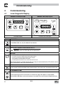
4.1
Local Keypad & Display
SMV Models: 0.33-10HP (0.25-7.5kW)
AUTO
SMV Models: 15HP (11kW) and greater
FWD
REMOTE
LOCAL
CTRL
MAN
AUTO
RPM
Hz
%
AMPS
/UNITS
REV
RUN
AUTO
FWD
REV
RUN
STOP
STOP
4-Character Display
Display
4-Character plus CTRL Display
START BUTTON
In Local Mode (P100 = 0, 4, 6), this button will start the drive.
RUN
STOP BUTTON
Stops the drive, regardless of which mode the drive is in.
WARNING!
When JOG is active, the STOP button will not stop the drive!
STOP
ROTATION
In Local Mode (P100 = 0, 4, 6), this selects the motor rotation direction:
- The LED for the present rotation direction (FWD or REV) will be on
- Press R/F; the LED for the opposite rotation direction will blink
- Press M within 4 seconds to confirm the change
- The blinking direction LED will turn on, and the other LED will turn off
When rotation direction is changed while the drive is running, the commanded direction LED will blink until the
drive is controlling the motor in the selected direction.
MODE
Used to enter/exit the Parameter Menu when programming the drive and to enter a changed parameter value.
UP AND DOWN BUTTONS
Used for programming and can also be used as a reference for speed, PID setpoint, or torque setpoint.
When the s and t buttons are the active reference, the middle LED on the left side of the display will be on.
22
SV01L
Commissioning
Display
INDICATING LEDs (on 4-character display)
FWD
FWD LED: Indicate the present rotation direction is forward. Refer to ROTATION description above.
REV LED: Indicate the present rotation direction is reverse. Refer to ROTATION description above.
REV
AUTO LED: Indicates that the drive has been put into Auto mode from one of the TB13 inputs (P121…P124 set
to 1…7). Indicates that PID mode is active (if PID mode is enabled). Indicates that sequencer mode is active (if
sequencer mode is enabled).
AUTO
RUN LED: Indicates that the drive is running.
RUN
s t LED: Indicates that the s t are the active reference.
NOTE
If the keypad is selected as the auto reference (P121…P124 is 6) and the corresponding
TB-13 input is closed, the AUTO LED and s t LEDs will both be on.
FUNCTIONS THAT FOLLOW ARE APPLICABLE TO SMV DRIVES 15HP (11kW) AND HIGHER
CTRL
CTRL
The CTRL pushbutton selects the start and speed reference control sources for the drive.
Press [
] mode button to accept the new control mode selection.
CTRL LEDs
REMOTE
LOCAL
REMOTE
LOCAL
REMOTE
LOCAL
REMOTE
LOCAL
MAN
AUTO
MAN
AUTO
MAN
AUTO
MAN
AUTO
START CONTROL
REFERENCE CONTROL
[LOCAL] [MAN]
Keypad
P101 Settings
[LOCAL] [AUTO]
Keypad
Terminal 13x Settings
[REMOTE] [MAN]
Terminal Strip
P101 Settings
[REMOTE] [AUTO]
Terminal Strip
Terminal 13x Settings
If P100 = 6 the CTRL button is used to toggle
start control between the terminal strip [REMOTE]
and the keypad [LOCAL]
- REM/LOC LED indicating the present start control source is ON
- Press [CTRL]; the LED for other start control source will blink
- Press [M] within 4 sec to confirm the change
- Blinking LED will turn ON (the other LED will turn OFF)
If P113 = 1 the CTRL button is used to toggle
reference control between the TB-13x setup
[AUTO] and P101 [MANUAL]
- AUT/MAN LED indicating present reference control is ON
- Press [CTRL]; the other reference control will blink
- Press [M] within 4 sec to confirm change
- Blinking LED will turn ON (the other LED will turn OFF)
If P100 = 6 and P113 = 1, it is possible to
change the start and reference control sources at
the same time
SV01L
23
Commissioning
Display
START CONTROL
The REMOTE/LOCAL LEDs indicate the current start control source. If the start control source is a remote keypad
or the network, then both LEDs will be OFF.
REFERENCE CONTROL
The AUTO/MANUAL LEDs indicate the current reference control source.
IF P113 = 0 or 2, the AUTO/MANUAL LEDs will match the AUTO LED on the 4-character display. IF P113 = 0
and no AUTO reference has been setup on the terminal strip, the MANUAL LED will turn ON and the AUTO LED
will turn OFF.
IF P113 = 1, the AUTO/MANUAL LEDS show the commanded reference control source as selected by the [CTRL]
button. If the [CTRL] button is used to set the reference control source to AUTO but no AUTO reference has been
setup on the terminal strip, reference control will follow P101 but the AUTO LED will remain ON.
UNITS LEDs
HZ: current display value is in Hz
In Speed mode, if P178 = 0 then HZ LED will be ON. If
P178 > 0, the Units LEDs follow the setting of P177 when
the drive is in run (non-programming) mode.
RPM: current display value is in RPM
In Torque mode, the HZ LED will be ON when the drive is
AMPS: current display value is in Amps
in run (non-programming) mode.
/UNITS current display value is a per unit (i.e./sec, In Pid mode, the Units LEDs follow the setting of P203
/min, /hr, etc.)
when the drive is in run (non-programming) mode.
If P179 > 0, the Units LEDs will show the unit of the
diagnostic parameter that is being displayed.
%: current display value is in %
4.2
Drive Display and Modes of Operation
Speed Mode Display
In the standard mode of operation, the drive frequency output is set directly by the selected reference (keypad, analog
reference, etc.). In this mode, the drive display will show the drive’s output frequency.
PID Mode Display
When the PID mode is enabled and active, the normal run display shows the actual PID setpoint. When PID mode is not
active, the display returns to showing the drive’s output frequency.
Torque Mode Display
When the drive is operating in Vector Torque mode, the normal run display shows the drive’s output frequency.
Alternate (Run-Screen) Display
When P179 (Run Screen Display) is set to a value other than 0, one of the diagnostic parameters (P501…P599) is
displayed. Example: if P179 is set to 1, then diagnostic parameter P501 (Software version) is displayed. If P179 =2,
then P502 (Drive ID) is displayed.
24
SV01L
Commissioning
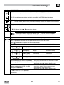
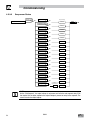
4.3
Parameter Setting
Status/Fault messages
StoP
60.0
Change Parameters
P194 = 0000
M
PASS
M
CL
Err
p100
p104
0225
M
F.AF
F.UF
4.4
p541
15 s
20.0
12.0
M
60 s
V0106
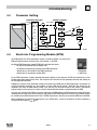
Electronic Programming Module (EPM)
The EPM contains the drives operational memory. Parameter settings are stored in the
EPM and setting changes are made to the “User settings” in the EPM.
An optional EPM Programmer (model EEPM1RA) is available that allows:
• An EPM to be copied directly to another EPM.
• An EPM to be copied to the memory of the EPM Programmer.
• Stored files can be modified in the EPM Programmer.
• Stored files can be copied to another EPM.
EPM Module
in SMV Drive
As the EPM Programmer is battery operated, parameter settings can be copied to an EPM and inserted into a drive
without power being applied to the drive. This means that the drive will be fully operational with the new settings on
the next application of power.
Additionally, when the drives parameter settings are burned into an EPM with the EPM Programmer, the settings are
saved in two distinct locations; the “User settings” and the “OEM default settings”. While the User settings can be
modified in the drive, the OEM settings cannot. Thus, the drive can be reset not only to the “factory” drive default
settings (shown in this manual), but can be set to the Original Machine settings as programmed by the OEM.
The user area contents of the EPM are what are copied into the OEM space by the EPM programmer. When parameter
modifications are made to the drive and then a copy made via the EPM Programmer, these are the settings that will
be available by the OEM selections from P199. The EPM Programmer is the only way to load the OEM area of the EPM.
While the EPM can be removed for copying or to use in another drive, it must be installed for the drive to operate (a
missing EPM will trigger an
1 fault)
SV01L
25
Commissioning
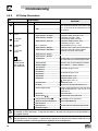
4.5
Parameter Menu
4.5.1
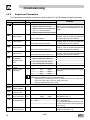
Basic Setup Parameters
Code
No.
Possible Settings
Name
Default Selection
Start Control Source
0
0 Local Keypad
1 Terminal Strip
IMPORTANT
2 Remote Keypad Only
3 Network Only
4 Terminal Strip or Local Keypad
5 Terminal Strip or Remote Keypad
6 CTRL button select
Use RUN button on front of drive to start
Use start/stop circuit wired into the terminal strip.
Refer to section 3.2.3
Use RUN button on optional Remote Keypad to start
• Start command must come from network
(Modbus, CANopen, etc)
• Requires optional communication module (refer
to the network module documentation).
• Must also set one of the TB-13 inputs to 9
(Network Enable); see P121...P124
Allows start control to be switched between
terminal strip and local keypad using one of the
TB-13 inputs. See note below.
Allows start control to be switched between
terminal strip and optional remote keypad using
one of the TB-13 inputs. See Note below
Allows start control to be switched between
terminal strip and local keypad using the CTRL
button.
NOTE: P100 Selection 6 is applicable to SMV 15HP
(11kW) and higher models only.
WARNING!
P100 = 0 disables TB-1 as a STOP input! STOP circuitry may be disabled if parameters are
reset back to defaults (see P199)
NOTE
• P100 = 4, 5: To switch between control sources, one of the TB-13 inputs (P121...P124)
must be set to 08 (Control Select);
TB-13x OPEN (or not configured): Terminal strip control
TB-13x CLOSED: Local (P100 = 4) or Remote (P100 = 5) keypad
• P100 = 0, 1, 4, 6: Network can take control if P121...P124 = 9 and the corresponding
TB-13x input is CLOSED.
• The STOP button on the front of the drive is always active except in JOG mode.
• TB-1 is an active STOP input if P100 is set to a value other than 0.
• An
fault will occur if the Assertion Level switch (ALsw) position does not match
the P120 setting and P100 is set to a value other than 0.
Standard Reference
Source
0 Keypad (Local or Remote)
1 0-10 VDC
2 4-20 mA
3 Preset #1
4 Preset #2
5 Preset #3
6 Network
7 Preset Sequence Segment #1
8 Preset Sequence Segment #2
9 Preset Sequence Segment #3
(1) Any changes to this parameter will not take effect until the drive is stopped
26
0
SV01L
Selects the default speed or torque reference
when no Auto Reference is selected using the
TB-13 inputs.
Selections 7, 8 & 9 are not valid for PID setpoint
or torque reference.
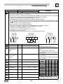
Commissioning
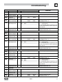
Code
No.
0
Possible Settings
Name
Default Selection
Minimum Frequency
0.0
0.0
{Hz}
P103
Maximum Frequency
{Hz}
500
60.0
7.5
IMPORTANT
• P102, P103 are active for all speed references
• When using an analog speed reference, also
see P160, P161
NOTE
• P103 cannot be set below Minimum Frequency (P102)
• To set P103 above 120 Hz:
- Scroll up to 120 Hz; display shows
(flashing).
- Release s button and wait one second.
- Press s button again to continue increasing P103.
0
WARNING!
Consult motor/machine manufacturer before operating above rated frequency. Overspeeding the motor/machine may cause
damage to equipment and injury to personnel!
Acceleration Time 1
20.0 0.0
{s}
3600
• P104 = time of frequency change from 0 Hz to
P167 (base frequency)
• P105 = time of frequency change from P167 to
Deceleration Time 1
20.0 0.0
{s}
3600
0 Hz
• For S-ramp accel/decel, adjust P106
EXAMPLE: IF P103 = 120 Hz, P104 = 20.0 s and P167 (base frequency) = 60 Hz; then the rate of frequency change from 0
Hz to 120 Hz = 40.0 s
S-Ramp Integration
Time
0.0
0.0
{s}
50.0
7(1) Line Voltage Selection
1*
0 Low (120, 200, 400, 480VAC)
1 High (120, 240, 480, 600VAC)
Motor Overload
100
30
{%}
100
• P106 = 0.0: Linear accel/decel ramp
• P106 > 0.0: Adjusts S-ramp curve for smoother
ramp
* The default setting is 1 for all drives except when
using “reset 50” (Parameter P199, selection
4) with 480V models. In this case, the default
setting is 0.
P108 = motor current rating x 100
SMV output rating
Example: if motor = 3amps and SMV = 4amps,
then P108 = 75%
NOTE
Do not set above rated motor current as listed on the motor dataplate. The motor thermal
overload function of the SMV is UL approved as a motor protection device. Cycling power after
an overload fault could result in significantly reducing the motor life.
Motor Overload Type
0
0 Speed Compensation
Ir
100%
1
0
60%
1 No Speed Compensation
30
SV01L
f
V0108
27
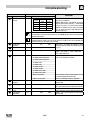
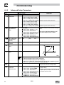
Commissioning
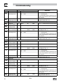
Code
No.
1
Name
Start Method
Possible Settings
Default Selection
0
0 Normal
1 Start on Power-up
2 Start with DC Brake
3 Auto Restart
4 Auto Restart with DC Brake
5 Flying Start/Restart #1
6 Flying Start/Restart #2
IMPORTANT
Drive will automatically start when power is
applied.
When start command is applied, drive will apply
DC braking according to P174, P175 prior to
starting the motor
Drive will automatically restart after faults, or when
power is applied.
Combines settings 2 and 3
• Drive will automatically restart after faults, or
when power is applied.
• After 3 failed attempts, drive will Auto Restart
with DC brake.
• P110 = 5: Performs speed search, starting at
Max Frequency (P103)
• P110 = 6: Performs speed search, starting at the
last output frequency prior to faulting or power
loss
• If P111 = 0, a flying START is performed when
a start command is applied.
NOTE
• P110 = 0, 2: Start command must be applied at least 2 seconds after power-up;
fault will occur if start command is applied too soon.
• P110 = 1, 3…6: For automatic start/restart, the start source must be the terminal strip
and the start command must be present.
• P110 = 2, 4…6: If P175=999.9, dc braking will be applied for 15s.
• P110 = 3…6: Drive will attempt 5 restarts; if all restart attempts fail, drive displays
(fault lockout) and requires manual reset.
• P110 = 5, 6: If drive cannot catch the spinning motor, drive will trip into . fault.
WARNING!
Automatic starting/restarting may cause damage to equipment and/or injury to personnel! Automatic starting/restarting should
only be used on equipment that is inaccessible to personnel.
1
Stop Method
0
0 Coast
1 Coast with DC Brake
2 Ramp
3 Ramp with DC Brake
1
28
Rotation
0
0 Forward Only
1 Forward and Reverse
SV01L
Drive’s output will shut off immediately upon a stop
command, allowing the motor to coast to a stop
The drive’s output will shut off and then the DC
Brake will activate (refer to P174, P175)
The drive will ramp the motor to a stop according
to P105 or P126.
The drive will ramp the motor to 0 Hz and then
the DC Brake will activate (refer to P174, P175)
If PID mode is enabled, reverse direction is disabled
(except for Jog).
Commissioning
Code
No.
1
Possible Settings
Name
Default Selection
Auto/Manual Control
0
0 Terminal Strip Control
1 Auto/Manual (CTRL button select)
2 Manual Control Only
IMPORTANT
The reference is dictated by the settings and state
of the TB-13x terminals. If no AUTO reference has
been setup on the terminal strip then reference
control is dictated by P101.
Allows the reference to be switched between auto
and manual using the CTRL pushbutton on the
drive keypad. If the CTRL pushbutton has selected
AUTO reference but no AUTO reference has been
setup on the terminal strip, then reference control
is dictated by P101.
Reference is dictated by P101 regardless of any
AUTO source that may be selected by the TB-13x
terminals.
NOTE
P113 is applicable to SMV 15HP (11kW) and higher models only.
1
MOP Speed
Initialization at
Power-Up
0
0 Set to last MOP speed at power up
1 Set to 0.0Hz at power up
2 Set to Preset #3 at power up
SV01L
29
Commissioning
4.5.2
Code
No.
I/O Setup Parameters
Name
Assertion Level
Possible Settings
Default Selection
2
1 Low
IMPORTANT
P120 and the Assertion Level switch must both
match the desired assertion level unless P100,
P121…P124 are all set to 0. Otherwise an F.AL
fault will occur.
2 High
TB-13A Input
Function
2
TB-13B Input
Function
2
TB-13C Input
Function
2
TB-13D* Input
Function
NOTE: P124 is
applicable to SMV
15HP (11kW) and
higher models only
0
0 None
1 AUTO Reference: 0-10 VDC
2 AUTO Reference: 4-20 mA
3 AUTO Reference: Preset #1
* 13D: 3 = Reserved
4 AUTO Reference: MOP Up
5 AUTO Reference: MOP Down
6 AUTO Reference: Keypad
7 AUTO Reference: Network
8 Control Select
9 Network Enable
10 Reverse Rotation
11 Start Forward
12 Start Reverse
13 Run Forward
14 Run Reverse
15 Jog Forward
16 Jog Reverse
Disables input
For frequency mode, see P160...P161,
For PID mode, see P204…P205,
For vector torque mode, see P330
For frequency mode see P131...P137,
For PID mode, see P231…P233,
For torque mode see, P331…P333
• Normally open: Close input to increase or
decrease speed, PID or torque setpoint.
• MOP Up is not active while in STOP
Use when P100 = 4, 5 to switch between terminal
strip control and local or remote keypad control.
Required to start the drive through the network.
Open = Forward
Closed = Reverse
Refer to Note for typical circuit
Refer to Note for typical circuit
17 Accel/Decel #2
18 DC Brake
19 Auxiliary Ramp to Stop
20 Clear Fault
21 External Fault .
22 Inverse External Fault .
23 AUTO Ref: Sequence Segment #1
24 Start Sequence
25 Step Sequence
26 Suspend Sequence
Jog Forward speed = P134
Jog Reverse speed = P135
Active even if P112 = 0
Refer to P125, P126
Refer to P174; close input to override P175
Normally closed: Opening input will ramp drive
to STOP according to P127, even if P111 is set
to Coast (0 or 1).
Close to reset fault
Normally closed circuit; open to trip
Normally open circuit; close to trip
Works in Speed Mode only
Transition from non-asserted to asserted state
WARNING
Jog overrides all STOP commands! To stop the drive while in Jog mode, the Jog input must be deactivated or a
fault condition induced.
WARNING
If the input defined to “Start Sequence” is opened during a sequence, the drive will exit sequencer mode and will run
at the specified standard or alternate speed source (dependent on drive configuration).
30
SV01L
Commissioning
Code
No.
Possible Settings
IMPORTANT
Name
Default Selection
NOTE
• When input is activated, settings 1...7 override P101
• When TB-13A...TB-13D are configured for Auto References other than MOP, TB-13D overrides TB-13C, TB-13C overrides
TB-13B and TB-13B overrides TB-13A. Any other Auto Reference will have priority over MOP.
• Settings 10...14 are only valid in Terminal Strip mode (P100 = 1, 4, 5, 6)
• If Start/Run/Jog Forward and Start/Run/Jog Reverse are both activated, drive will STOP
• If Jog input is activated while drive is running, the drive will enter Jog mode; when Jog input is deactivated, drive will STOP
• An
fault will occur if the Assertion Level switch (ALsw) position does not match the P120 setting and any of the digital
inputs (P121...P124) are set to a value other than 0.
fault will occur under the following conditions:
• An
- TB-13A...TB-13D settings are duplicated (each setting, except 0 and 3, can only be used once)
- One input is set to “MOP Up” and another is not set to “MOP Down”, or vice-versa.
- One input is set to 10 and another input is set to 11…14.
- One input is set to 11 or 12 and another input is set for 13 or 14.
• Typical control circuits are shown below:
- If any input is set to 10, 12 or 14, P112 must be set to 1 for Reverse action to function.
Run / Stop
with Direction
P121 = 10
1
Start Forward /
Start Reverse
P121 = 11, P122 = 12
1
13A
4
STOP
FWD
RUN
REV
4
Run Forward /
Run Reverse
P121 = 13, P122 = 14
13A 13B
1
RUN
FWD
FWD
STOP
13A 13B
4
RUN
REV
REV
Acceleration Time 2
20.0
0.0
{s}
3600
P 26 Deceleration Time 2
20.0
0.0
{s}
3600
7 Deceleration Time
20.0
0.0
{s}
3600
Automatic Accel/
Decel rate switch
threshold
0.0
0.0
{Hz}
1000
Preset Speed #1
0.0
0.0
{Hz}
500
Preset Speed #2
0.0
0.0
{Hz}
500
Preset Speed #3
0.0
0.0
{Hz}
500
Preset Speed #4
0.0
0.0
{Hz}
500
Preset Speed #5
0.0
0.0
{Hz}
500
Preset Speed #6
0.0
0.0
{Hz}
500
7 Preset Speed #7
0.0
0.0
{Hz}
500
Preset Speed #8
0.0
0.0
{Hz}
500
for Auxiliary Ramp
to Stop
SV01L
• Selected using TB-13A...TB-13D (P121...P124
= 17)
• For S-ramp accel/decel, adjust P106
• Selected using TB-13A...TB-13D (P121...P124
= 19).
• For S-ramp accel/decel, adjust P106
• Once executed, this ramp time has priority over
P105 and P126.
If Actual Frequency < P129 Use Accel/decel time
#2 (P125/P126)
If Actual Frequency > P129 Use Accel/decel time
#1 (P104/P105)
PRESET
SPEED
1
2
3
4
4 (alternate)
5
6
7
8 (alternate)
8 (alternate
13A
13B
13C
13D
X
--X
-X
-X
---
-X
-X
--X
X
X
--
--X
--X
X
X
-X
----X
---X
X
• Speed setting is used by P158
• 13D available on 15HP (11kW) & higher drives.
31
Commissioning
Code
No.
Name
Relay Output
TB-16, 17
Possible Settings
Default Selection
0
0 None
1 Run
2 Reverse
3 Fault
IMPORTANT
4 Inverse Fault
5 Fault Lockout
6 At Speed
7 Above Preset Speed #6
8 Current Limit
9 Follower Loss (4-20 mA)
10 Loss of Load
11 Local Keypad Control Active
12 Terminal Strip Control Active
13 Remote Keypad Control Active
14 Network Control Active
15 Standard Reference Active
16 Auto Reference Active
17 Sleep Mode Active
18 PID Feedback < Min. Alarm
19 Inverse PID Feedback < Min. Alarm
20 PID Feedback > Max Alarm
21 Inverse PID Feedback > Max Alarm
22 PID Feedback within
Min/Max Alarm range
23 PID Feedback outside
Min/Max Alarm range
24 Reserved
25 Network Controlled
TB-14 Output
32
0
26 Loss of 0-10V Input
27 Sequencer Controlled
28 Sequencer Active
29 Sequencer Suspended
30 Sequence Done
31 Actual Speed = 0.0Hz
0...23 (same as P140)
24 Dynamic Braking
25...31 (same as P140)
SV01L
Disables the output
Energizes when the drive is running
Energizes when reverse rotation is active
De-energizes when the drive trips, or power is
removed
Energizes when the drive trips
P110 = 3...6: De-energizes if all restart attempts
fail
Energizes when output frequency = commanded
frequency
Energizes when output frequency > P136
Energizes when motor current = P171
Energizes when 4-20 mA signal falls below 2 mA
Energizes when motor load drops below P145;
Refer to P146 also
Energizes when the selected source is active for
start control
Energizes when P101 reference is active
Energizes when Auto Reference is activated using
TB-13 input; refer to P121...P124
Refer to P240...P242
Energizes when PID feedback signal < P214
De-energizes when PID feedback signal < P214
Energizes when PID feedback signal > P215
De-energizes when PID feedback signal > P215
Energizes when PID feedback signal is within the
Min/Max Alarm range; refer to P214, P215
Energizes when PID feedback signal is outside the
Min/Max Alarm range; refer to P214, P215
Requires optional communication module (refer to
the network module documentation).
State set in individual sequencer segments
End Sequence
For use with Dynamic Braking option
Commissioning
Code
No.
Name
Digital Output
Inversion
Possible Settings
Default Selection
P144
0
1
2
3
IMPORTANT
Invert
P142
NO
NO
YES
YES
Invert
P140
NO
YES
NO
YES
Used to invert the selections for P140 (Relay Output)
and P142 (TB-14 Output).
EXAMPLE: When P140 = 6 (AT SPEED), the relay is
energized when output frequency = commanded
frequency. IF P144=1 or 3, then P140 is inverted
(INVERSE AT SPEED) and the relay is energized
when the output frequency does not equal the
command frequency.
Loss of Load
Threshold
Loss of Load Delay
0.0
NOTE
Inverting P140 or P142 when the parameter is set to NONE (0) will result in the output being
energized continuously.
NOTE
For SMVector drives rated at 0.33 to 10 HP (0.25 to 7.5 kW), P144 is only available with
software versions 3.0 and higher (refer to P501).
0
{%}
200
P140, P142 = 10: Output will energize if motor
load falls below the P145 value longer than the
P146 time
0.0
{s}
240.0
Analog Offset
0.0
0
{%}
TB-30 Output
0
0
1
2
3
4
5
6
7
8
9
None
0-10 VDC Output Frequency
2-10 VDC Output Frequency
0-10 VDC Load
2-10 VDC Load
0-10 VDC Torque
2-10 VDC Torque
0-10 VDC Power (kW)
2-10 VDC Power (kW)
Network Controlled
0
100
TB-30 Scaling:
Frequency
TB-30 Scaling: Load
60.0
10 Sequencer Controlled
3.0
{Hz}
2000
200
10
{%}
500
TB-30 Scaling:
Torque
TB-30 Scaling:
Power (kW)
100
10
{%}
1000
1.0
0.1
{kW}
200.0
SV01L
Scaled value. Example: P149 = 10%, Scaled
variable = freq, P150 = 1, P152 = 60Hz; then
TB30 = 0VDC below 6Hz
2-10 VDC signal can be converted to 4-20 mA with
a total circuit impedance of 500 W
Requires optional communication module (refer to
the network module documentation).
Value set in individual sequencer segments
If P150 = 1 or 2, sets the frequency at which output
equals 10 VDC
If P150 = 3 or 4, sets the Load (as a percent of
drive current rating) at which output equals 10 VDC.
If P150 = 5 or 6, sets the Torque (as a percent of
motor rated torque) at which output equals 10 VDC
If P150 = 7 or 8, sets the power at which output
equals 10 VDC
33
Commissioning
4.5.3
Code
No.
Advanced Setup Parameters
Name
Analog Inputs
Configuration
7 TB5 (0-10V) Analog
Input Monitoring
Action
P
P1
Possible Settings
IMPORTANT
Default Selection
0 TB5: (0-10 VDC); TB25: (4-20mA)
1 TB5: (0 - 5 VDC); TB25: (4-20mA)
2 TB5: (2 - 10 VDC); TB25: (4-20mA)
3 TB5: (-10 - +10 VDC); TB25: (4-20mA) Available on special option module only
4 TB5: (0-10 VDC); TB25: (0-20mA)
5 TB5: (0 - 5 VDC); TB25: (0-20mA)
6 TB5: (2 - 10 VDC); TB25: (0-20mA)
7 TB5: (-10 - +10 VDC); TB25: (0-20mA) Available on special option module only
0 No Action
Selects the reaction to a loss of the 0-10V signal
at TB5
1 P157 < P158 - Trip Fault F.FAU
TB5 (0-10V) Analog
Input Monitoring
Level (ML)
0-10V Analog Input
Deadband
Speed at Minimum
Signal
0.0
2 P157 < P158 - Run Preset #8
Minimum time above/below Monitoring Level
3 P157 < P158 - Run Preset Seq. #16 (P158) before triggering action is 500ms.
4 P157 > P158 - Trip Fault F.FAU
5 P157 > P158 - Run Preset #8
6 P157 > P158 - Run Preset Seq. #16
-10.0
{VDC}
10.0
0.0
0
{VDC}
10.0
0.0
-999.0
{Hz}
1000
Speed at Maximum
Signal
60.0
-999.0
{Hz}
1000
Not active if [-10 to +10 VDC] option is selected.
f
P161
0V
(4mA)
10V
(20mA)
ref
P160
V0111
p1
34
Analog Input Filter
0.01
TB-25 (4-20mA)
Analog Input
Monitoring Action
0
NOTE
• P160 sets the output frequency at 0% analog input
• P161 sets the output frequency at 100% analog input
• P160 or P161 < 0.0 Hz: For scaling purposes only; does not indicate opposite direction!
• P160 > P161: Drive will react inversely to analog input signal
0.00
{s}
10.00
Adjusts the filter on the analog inputs (TB-5 and
TB-25) to reduce the effect of signal noise
0 No Action
• Selects the reaction to a loss of the 4-20 mA
signal at TB-25.
1 P163 < P164 - Trip Fault
• Signal is considered lost if it falls below 2 mA
2 P163 < P164 - Run Preset #7
• Digital outputs can also indicate a loss of 4-20
3 P163 < P164 - Run Preset Seq. #15
mA signal; see P140, P142
4 P163 > P164 - Trip Fault
5 P163 > P164 - Run Preset #7
6 P163 > P164 - Run Preset Seq. #15
SV01L
Commissioning
Code
No.
Name
TB-25 (4-20mA)
Analog Input
Monitoring Level
Base Voltage
P1
P1
p
(1)
p
Possible Settings
Default Selection
2.0
0.0
15
IMPORTANT
{mA}
20.0
{V}
1000
4 kHz
6 kHz
8 kHz
10 kHz
Valid for V/Hz mode only.
Set voltage for bus compensation in V/Hz mode
• As carrier frequency is increased, motor noise
is decreased
• Observe derating in section 2.3
• Automatic shift to 4 kHz at 120% load
• NEMA 4X (IP65) Models: Default = 0 (4kHz)
• NEMA 1 (IP31) Models: Default = 1 (6kHz)
Carrier Frequency
See
Notes
0
1
2
3
Base Frequency
60.0
25.0
{Hz}
1500
Fixed Boost
0.0
{%}
40.0
Accel Boost
0.0
NOTE
• P167 = rated motor frequency for standard applications
• P165, P168 = default setting depends on drive rating
0.0
{%}
20.0
Accel Boost is only active during acceleration
Slip Compensation
0.0
0.0
{%}
40.0
{%}
50.0
V0112
P 7
(1)
7
P17
Decel Override Time
2.0
Increase P170 until the motor speed no longer
changes between no load and full load conditions.
30
{%}
Max I
• When the limit is reached, the drive displays
(Current Limit), and either the acceleration
time increases or the output frequency
decreases.
• Digital outputs can also indicate when the limit
is reached; see P140, P142.
• Refer to section 2.3 for the maximum output
current Max I (%)
0 Current Limit Reduction Active - In field weakening, the Current Limit is inversely
Normal response
proportional to the speed.
1 Current Limit Reduction Active - Fast
response
2 Current Limit Reduction Disabled Normal response
3 Current Limit Reduction Disabled Fast response
0.0
{s}
60.0
Maximum time before drive trips into HF fault.
DC Brake Voltage
0.0
0.0
Current Limit
Max I
Current Limit
Reduction
0
Setting is a percent of the nominal DC bus voltage.
(1) Any changes to this parameter will not take effect until the drive is stopped
SV01L
35
Commissioning
Code
No.
Name
DC Brake Time
p17
p
77
)
Keypad Setpoint
Single Press
Increment
Speed Units
Possible Settings
IMPORTANT
Default Selection
0.0
0.0
{s}
999.9
NOTE: CONFIRM MOTOR SUITABILITY FOR USE WITH DC BRAKING
DC Brake voltage (P174) is applied for the time specified by P175 with the following exceptions:
• If P111=1, 3 and P175=999.9 the brake voltage will be applied continuously until a run
or fault condition occurs.
• If P110=2, 4…6 and P175=999.9, brake voltage will be applied for 15s
• If P121…P124=18 and the corresponding TB-13 input is CLOSED, brake voltage will be
applied until the TB-13 input is OPENED or a fault condition occurs.
0.1
0.1
100.0
Used for run screen setpoint editing only.
If P176 >0.1 then scrolling of keypad setpoint
is disabled.
0
0 Hz
Select the UNITS LED that will be illuminated when
the drive is running in speed control mode. For this
1 RPM
parameter to be used, P178 must be set to a value
2 %
other than 0. IF P178 is set to 0, the Hz LED will
3 /UNITS
be illuminated regardless of the value set in P177.
4 NONE
0.00 0.00
650.00
• Allows frequency display to be scaled
• P178 = 0.00: Scaling disabled
• P178 > 0.00: Display = Actual Frequency X
P178
EXAMPLE
If P178 = 29.17 and actual frequency = 60 Hz, then Drive displays 1750 (rpm)
p17
Display Frequency
Multiplier
p
Run Screen Display
0
0
0
0
80
p
Oscillation Damping
Control
Skip frequency 1
0.0
0.0
{Hz}
500
Skip frequency 2
0.0
0.0
{Hz}
500
Skip frequency
bandwidth
0.0
0.0
{Hz}
10.0
Voltage Midpoint
V/Hz characteristic
Frequency Midpoint
V/Hz characteristic
Integrated Dynamic
Brake
0
0.0
{Parameter Number}
599
NOTE
Bandwidth (Hz) = fs (Hz) + P184 (Hz)
fs = P181 or P182
EXAMPLE: P181 = 18 Hz and P184 = 4 Hz; skip range is from 18 to 22 Hz
0.0
{V}
P165
Valid only when P300 = 0 or 2.
Use with P187 to define midpoint on V/Hz curve.
0.0
{Hz}
P167
Valid only when P300 = 0 or 2.
Use with P185 to define midpoint on V/Hz curve.
0 Disabled
1 Enabled
(2) Parameter applicable to SMV models 15HP (11kW) and higher.
(3) Parameter applicable to SMV models 40HP (30kW) and higher.
36
• 0 = Normal Run Screen, this display depends
on mode of operation. Refer to section 4.2.
• Other selections choose a diagnostic parameter
to display (P501…P599).
• Parameters P560 - P564 are selectable if
the sequencer is enabled (P700 is not 0).
P560-P564 are not visible until P700 is enabled.
0 = Damping disabled
Compensation for resonances within drive
• Drive will not run in the defined skip range; used
to skip over frequencies that cause mechanical
vibration
• P181 and P182 define the start of the skip
ranges
• P184 > 0 defines the bandwidth of both ranges.
SV01L
Commissioning
Code
No.
Name
Motor Braking
Motor Brake Level
9
P1
Motor Braking
Deceleration
Reduction Level
Possible Settings
Default Selection
0 Disabled
1 Braking with BUS threshold
2 Braking always on with deceleration
3 Braking with bus regulator
4 Special (Consult factory before using)
0
0
{%}
75
(flux
braking
disabled)
0.0
Password
0
Clear Fault History
0
Program Selection
IMPORTANT
Active when P190 > 0 and drive is in deceleration
mode. Use to reduce deceleration time on high
inertia loads.
NOTE: Over usage of P190 can cause frequent
‘overload’ trips “F.PF”
Not active for P300 = 5 (Torque mode)
0
P167
Active when P190 > 0 and P192 > 0.0, Drive is
(base freq) in deceleration mode. Use to reduce deceleration
time on high inertia loads.
Raising the value of P191 reduces the NOTE: Usage of P192 can cause the drive to
drive deceleration rate during flux braking. decelerate faster than settings in P105/P127.
Not active for P300 = 5 (Torque mode)
0000
9999
• Must enter password to access parameters
• P194 = 0000: Disables password
0 No Action
1 Clear Fault History
0 Operate from User settings
1 Operate from OEM settings
Refer to Notes 1, 2 and 3
2 Reset to OEM default settings
Refer to Note 1
3 Reset to 60 Hz default settings
• Refer to Note 4
• Parameters are reset to the defaults listed in
this manual.
• For P199=4, the following exceptions apply:
- P103, P152, P161, P167 = 50.0 Hz
4 Reset to 50 Hz default settings
- P304 = 50 Hz;
- P305 = 1450 RPM
- P107 = 0 (480 V drives only)
5 Translate
Refer to Note 5
WARNING!
Modification of P199 can affect drive functionality! STOP and EXTERNAL FAULT circuitry may
be disabled! Check P100 and P121...P124
NOTE 1
If the EPM does not contain valid OEM settings, a flashing GF will be displayed when P199
is set to 1 or 2.
NOTE 2
When P199 is set to 1, the drive operates from the OEM settings stored in the EPM Module
and no other parameters can be changed ( will be displayed if attempted).
NOTE 3
Auto Calibration is not possible when operating from OEM Settings.
NOTE 4
Reset 60 and Reset 50 will set the Assertion Level (P120) to “2” (High). P120 may need to
be reset for the digital input devices being used. An
fault may occur if P120 and the
Assertion switch are not set identically.
NOTE 5 - on next page.
SV01L
37
Commissioning
Code
No.
p1
4.5.4
Code
No.
P
Name
Program Selection
Possible Settings
IMPORTANT
Default Selection
NOTE 5
If an EPM that contains data from a previous compatible software version is installed:
• The drive will operate according to the previous data, but parameters cannot be changed
( will be displayed if attempted)
• To update the EPM to the current software version, set P199 = 5. The parameters can now
be changed but the EPM is incompatible with previous software revisions.
PID Parameters
Name
PID Mode
Possible Settings
Default Selection
0
0 Disabled
IMPORTANT
1 Normal-acting
2 Reverse-acting
3 Normal-acting, Bi-directional
4 Reverse-acting, Bi-directional
p
PID Feedback Source
0
p
PID Decimal Point
1
PID Units
0
3
Feedback at
Minimum Signal
Feedback at
Maximum Signal
p
p
0.0
100.0
NOTE
To activate PID mode, one of the TB-13 inputs (P121...P124) must be used to select the
Auto Reference that matches the desired PID setpoint reference. If the selected PID setpoint
reference uses the same analog signal as the PID feedback (P201), an I fault will occur.
Example: The desired PID setpoint reference is the keypad (s and t). Set TB-13x = 6
(Auto Reference: Keypad):
• TB-13x = closed: PID mode is active
• TB-13x = open: PID mode is disabled and the drive speed will be controlled by the reference
selected in P101.
0 4-20 mA (TB-25)
Must be set to match the PID feedback signal
1 0-10 VDC (TB-5)
2 Drive Load (P507)
3 Feedback from Network
0 PID Display = XXXX
Applies to P204, P205, P214, P215, P231...P233,
P242, P522, P523
1 PID Display = XXX.X
2 PID Display = XX.XX
3 PID Display = X.XXX
4 PID Display = .XXXX
0 %
Select the UNITS LED that will be illuminated when
the drive is running in PID control mode
1 /UNITS
2 AMPS
3 NONE
-99.9
3100.0
Set to match the range of the feedback signal
being used
Example: Feedback signal is 0 - 300 PSI; P204 =
-99.9
3100.0
0.0, P205 = 300.0
(2) Parameter applicable to SMV models 15HP (11kW) and higher.
38
• Normal-acting: As feedback increases, motor
speed decreases
• Reverse-acting: As feedback increases, motor
speed increases
• PID mode is disabled in Vector Torque mode
(P300 = 5)
• Selections 3, 4: If P112=1, PID controller output
sets the speed, (range -max freq to +max freq)
SV01L
Commissioning
Code
No.
Possible Settings
Default Selection
5.0
0.0
IMPORTANT
p
Name
Proportional Gain
{%}
1000.0
p
Integral Gain
0.0
0.0
{s}
20.0
Derivative Gain
0.0
0.0
{s}
20.0
Used to tune the PID loop:
• Increase P207 until system becomes unstable,
then decrease P207 by 10-15%
• Next, increase P208 until feedback matches
setpoint
• If required, increase P209 to compensate for
sudden changes in feedback
NOTE
• Derivative Gain is very sensitive to noise on the feedback signal. Use with care.
• Derivative Gain is not normally required in pump and fan applications
0.0
{s}
100.0
• time of setpoint change from P204 to P205 or
vice versa.
• Used to smooth the transition from one PID
setpoint to another, such as when using the
Preset PID Setpoints (P231...P233)
P204
P205
Use with P140, P142 = 18...23
PID Setpoint Ramp
20.0
p
Minimum Alarm
0.0
P
Maximum Alarm
0.0
P204
P205
Preset PID Setpoint #1
0.0
P204
P205
TB-13A activated; P121 = 3 and P200 = 1 or 2
Preset PID Setpoint #2
0.0
P204
P205
TB-13B activated; P122 = 3 and P200 = 1 or 2
Preset PID Setpoint #3
0.0
P204
P205
TB-13C activated; P123 = 3 and P200 = 1 or 2
Preset PID Setpoint #4
0.0
P204
P205
TB-13D activated; P124 = 3 and P200 = 1 or 2
Sleep Threshold
0.0
0.0
{Hz}
500.0
Sleep Delay
30.0
0.0
{s}
300.0
Sleep Bandwidth
0.0
• If drive speed < P240 for longer than P241,
output frequency = 0.0 Hz; drive display =
• P240 = 0.0: Sleep mode is disabled.
• P200 = 0…2: Drive will start again when speed
command is above P240
• P242 > 0.0: Drive will restart when the PID
feedback differs from the setpoint by more than
the value of P242 or when the PID loop requires
a speed above P240.
Active only when P244 = 1 or 2
P
P
P
0.0
Bmax
Where: Bmax = |(P205 - P204)|
Feedback Sleep
Entry Threshold
Sleep Entry Mode
0.0
45
Sleep Entry Stop
Type
0
4
Feedback Recovery
from Sleep Threshold
Sleep Recovery
Mode
43
44
47
0
0.0
0
P204
P205
0 Enter SLEEP if Drive Speed <P240
1 Enter SLEEP if Feedback >P243
2 Enter SLEEP if Feedback <P243
0 Coast to Stop
1 Ramp to Stop
2 Stop with P111 settings
P204
P205
For time longer than P241
For time longer than P241 or same as Sel 0
For time longer than P241 or same as Sel 0
Active only when P247 = 1 or 2
0 Recovery if Speed Setpoint > P240
or if PID feedback differs from setpoint
by more than P242
1 Recovery only if Feedback < P246
2 Recovery only if Feedback > P246
(2) Parameter applicable to SMV models 15HP (11kW) and higher.
SV01L
39
Commissioning
Code
No.
Possible Settings
Default Selection
0
0 Disabled
1 Enabled
Time Delay between
30.0 0.0
Auto Rinses
Auto Rinse Speed
0.0
-500.0
IMPORTANT
Name
Auto Rinse in Sleep
Mode
5
Auto Rinse Time
0.0
{min}
6553.5
Time delay reset by re/entering sleep mode
{Hz}
500.0
If P112 = 1, negative sign = reverse direction
0.0
{sec}
6553.5
Does not include time to decel back to speed
Auto Pump Rinse Setup:
Pump Rinse Speed
P250=1 (Enabled)
P252
P251=# minutes between each
P104/
P105/
P125
P126
PumpRinse
De ay Time
between each
P252=Hz speed of Pump Rinse
Pump Rinse Time
Pump Rinse
P251
P253
P253=# seconds Pump Rinse duration
Output Frequency
53
Activated in sleep mode only.
Sleep Recovery cancels Auto Rinse
Time
4.5.5
Code
No.
3
(1)
Vector Parameters
Name
Drive Mode
Possible Settings
Default Selection
0
0 Constant V/Hz
1 Variable V/Hz
IMPORTANT
2 Enhanced Constant V/Hz
3 Enhanced Variable V/Hz
4 Vector Speed
5 Vector Torque
3
3 3
(1)
Motor Rated Voltage
(1)
Motor Rated Current
Constant torque V/Hz control for general applications
Variable torque V/Hz control for centrifugal pump
and fan applications
For single or multiple motor applications that require
better performance than settings 0 or 1, but cannot
use Vector mode, due to:
• Missing required motor data
• Vector mode causing unstable motor operation
For single-motor applications requiring higher
starting torque and speed regulation
For single-motor applications requiring torque control
independent of speed
NOTE
To configure the drive for either Vector mode or Enhanced V/Hz mode:
• P300 = 4, 5:
- Set P302...P306 according to motor nameplate
- Set P399 = 1 or 2 (if option 1 failed or in case of non-standard motor)
- Make sure motor is cold (20° - 25° C) and apply a Start command
- Display will indicate
for about 40 seconds
- Once the calibration is complete, the display will indicate
; apply another Start
command to actually start the motor
- If an attempt is made to start the drive in Vector or Enhanced V/Hz mode before
performing the Motor Calibration, the drive will display
and will not operate
• P300 = 2, 3: Same as above but only need to set P302…P304
0
{V}
600
• Default setting = drive rating
0.1
{A}
500.0 • Set to motor nameplate data
(1) Any changes to this parameter will not take effect until the drive is stopped
40
SV01L
Commissioning
Code
No.
Name
Motor Rated
Frequency
Motor Rated Speed
3 4
(1)
3 5
3
(1)
(1)
Motor Cosine Phi
3
(1)
3
(1)
Motor Stator
Resistance
Motor Stator
Inductance
Dead Time
Compensation Factor
Torque Limit
1
3 3
{RPM}
65000
Set to motor nameplate data
300
100
0.40
0.99
NOTE If motor cosine phi is not known, use one of the following formulas:
cos phi = motor Watts / (motor efficiency X P302 X P303 X 1.732)
cos phi = cos [ sin 1 (magnetizing current / motor current) ]
0.00
{W}
64.00 • P310, 311 default setting depends on drive rating
• Will be automatically programmed by P399
• Changing these settings can adversely affect
0.0
{mH}
2000
performance. Contact factory technical support
prior to changing
-50.0
{%}
+50.0 • Adjust dead time correction from internal default
• Takes effect when P399 = 3.
0
{%}
400
When P300 = 5, sets the maximum output torque.
100
0
{%}
400
TB-13A activated; P121 = 3 and P300 = 5
100
0
{%}
400
TB-13B activated; P122 = 3 and P300 = 5
100
0
{%}
400
TB-13C activated; P123 = 3 and P300 = 5
100
0
{%}
400
TB-13D activated; P124 = 3 and P300 = 5
Changing these settings can adversely affect
performance. Contact factory technical support
prior to changing.
0.0
0.25
Current Loop I Gain
65
(1)
Speed Loop Adjust
Slip Compensation
Response Filter
Motor Autocalibration
0
(1)
1000
0.80
(1)
(2)
IMPORTANT
{Hz}
1750
Preset Torque
Setpoint #1
Preset Torque
Setpoint #2
Preset Torque
Setpoint #3
Preset Torque
Setpoint #4
Current Loop P Gain
1
3
Possible Settings
Default Selection
60
0
0.00
16.0
12
{ms}
9990
0.0
0.0
{%}
20.0
99
90
{ms}
9999
Low pass filter time constant for varying the slip
compensation response to changes in the motor
current.
0 Calibration Not Done
• If P300 = 4 or 5, motor calibration must be
performed if P399 is not set to 3 (bypass
1 Standard Calibration Enabled
calibration).
2 Advanced Calibration Enabled
• If P300=2 or 3, motor calibration is
3 Bypass Calibration, enable
recommended.
operation in vector mode w/o Auto
• Use option 2 if option 1 failed or in case of nonCalibration
standard motors
4 Standard Calibration Complete
• An alternating
/
will occur if:
5 Advanced Calibration Complete
- attempt motor calibration with P300 = 0 or 1
- motor calibration is attempted before
programming motor data
NOTE: To run the Auto Calibration:
−− Set P302...P306 according to motor nameplate
−− Set P399 = 1 or 2 (if option 1 failed or in case of non-standard motor)
−− Make sure motor is cold (20° - 25° C)
−− Apply a Start command
−− Display will indicate
for about 40 seconds
−− Once the calibration is complete, the display will indicate
; apply another
Start command to actually start the motor
−− Parameter P399 will now be set to 4 or 5.
(1) Any changes to this parameter will not take effect until the drive is stopped
(2) Parameter applicable to SMV models 15HP (11kW) and higher.
SV01L
41
Commissioning
4.5.6
Code
No.
Network Parameters
Possible Settings
Default Selection
0 Not Active
1 Remote Keypad
2 Modbus RTU
3 CANopen
4 DeviceNet
5 Ethernet
6 Profibus
7 Lecom-B
8 I/O Module
Module Type Installed
0
0 No Module Installed
1 Basic I/O (0x0100, 1.0.0)
2 RS485/Rem. Keypad (0x0200, 2.0.0)
3 CANopen (0x0300, 3.0.0)
11 PROFIBUS (0x1100, 11.0.0)
12 Ethernet (0x1200, 12.0.0)
Module Status
0
0 Not Initialized
1 Initialization: Module to EPM
2 Initialization: EPM to Module
3 Online
4 Failed Initialization Error
5 Time-out Error
6 Initialization Failed
7 Initialization Error
Module Reset
0
0 No Action
1 Reset parameters to default values
Module Timeout Action
0
0 No Fault
1 STOP (see P111)
2 Quick Stop
3 Fault (F_ntF)
Current Network Fault
0 No Fault
1 F.nF1
2 F.nF2
3 F.nF3
4 F.nF4
5 F.nF5
6 F.nF6
7 F.nF7
Proprietary
Name
Network Protocol
7…
42
Module Specific Parameters
SV01L
IMPORTANT
This parameter setting is based upon the network
or I/O module that is installed.
Module type format: 0xAABC; Drive Display:
AA.B.C
AA = Module Type
B = Major revision
C = minor revision
Module type mismatch P401
Protocol selection mismatch P400
Returns module parameters 401…499 to the
default values shown in the manual
Action to be taken in the event of a Module/
Drive Time-out.
Time is fixed at 200ms
STOP is by the method selected in P111.
NetIdle Mode
Loss of Ethernet I/O connection
Network Fault
Explicit Message Timeout
Overall Network Timeout
Overall Explicit Timeout
Overall I/O Message Timeout
Manufacturer specific
Refer to the Communications Reference Guide
specific to the network or I/O module installed.
Commissioning
4.5.7
Code
No.
Diagnostic Parameters
Display Range (READ ONLY)
Name
Fault History
• Displays the last 8 faults
• Format: n.xxx where: n = 1..8,
1 is the newest fault; xxx = fault message (w/o the .)
• Refer to section 5.3
Format: x.yz
Software Version
Drive ID
P
P
P
P
P
IMPORTANT
A flashing display indicates that the Drive ID stored in the EPM
does not match the drive model it is plugged into.
Alternating Display: xxx-; -yy
Internal Code
DC Bus Voltage
0
{VDC}
1500
Motor Voltage
0
{VAC}
1000
Load
0
{%}
255
Motor Current
0.0
{A}
1000
Motor load as % of drive’s output current rating.
Refer to section 2.3.
Actual motor current
Torque
0
{%}
500
Torque as % of motor rated torque (vector mode only)
Output Power kW
0.00
{kW}
650.0
Total kWh
0.0
{kWh}
Heatsink Temp
0
{°C}
150
Heatsink temperature
0-10 VDC Input
0.0
{VDC}
10.0
Actual value of signal at TB-5
4-20 mA Input
0.0
{mA}
20.0
Actual value of signal at TB-25
TB-5 Feedback
P204
P205
TB-5 signal value scaled to PID feedback units
TB-25 Feedback
P204
P205
TB-25 signal value scaled to PID feedback units
Network Feedback
P204
P205
Network signal value scaled to PID feedback units
Analog Output
0
{VDC}
10.0
Refer to P150…P155
Actual Output
Frequency
Network Speed
Command
Terminal and
Protection Status
Keypad Status
0
{Hz}
500.0
0
{Hz}
500.0
Total Run Time
0
{h}
9999999
Total Power On Time 0
{h}
9999999
Fault History
1
Fault History Time
0
{h}
Fault History Counter 0
9999999
8
999999
255
SV01L
Alternating display: xxx-; yyyy when value exceeds 9999
Command speed if (Auto: Network) is selected as the speed
source
Indicates terminal status using segments of the LED display.
(Refer to section 4.5.7.1)
Indicates keypad button status using segments of the LED
display. (Refer to section 4.5.7.2)
Alternating display: xxx-; yyyy when value exceeds 9999
• Displays the last 8 faults
• Format: n.xxx where: n = 1..8,
1 is the newest fault; xxx = fault message (w/o the .)
• Refer to section 5.3
Display: “n.hh-” “hhhh” “mm.ss” = fault #, hours, seconds
The “hhhh” screen is displayed after hours exceed 999.
Number of sequential occurrences of a fault.
For example: 3 external faults occur over a period of time
with no other errors occurring. Then P552 will indicate 3,
P550 will indicate the error EF and P551 will indicate the
time of the first fault occurrence.
43
Commissioning
Code
No.
Name
Sequencer: Currently
Active Segment
Sequencer: Time
since Start of Active
Segment
Sequencer: Time
Remaining in Active
Segment
Sequencer: Number
of cycles since start
Sequencer: Number
of cycles remaining
Display Range (READ ONLY)
IMPORTANT
0
17
0.0
0
{P708}
{P708}
6553.5
65535
Unit depends on P708 (0.1sec, sec or minutes)
0.0
0
{P708}
{P708}
6553.5
65535
Unit depends on P708 (0.1sec, sec or minutes)
0
65535
0
65535
NOTE: Parameters P560-P564 are visible only when P700 > 0 (i.e. the sequencer is enabled)
4.5.7.1 Terminal & Protection Status Display
Parameter P530 allows monitoring of the control terminal
points and common drive conditions:
An illuminated LED segment indicates:
• the protective circuit is active (LED 1)
• the Logic Assertion Switch is set to High (+)
• input terminal is asserted (LED 2)
• output terminal is energized (LED 4)
• the Charge Relay is not a terminal, this segment will
be illuminated when the Charge Relay is energized
(LED 4).
1
LED #
2
Current Limit Diagnostic
Logic Assertion Switch
Input 1
Input 13B
Relay
Output 14
Input 13D*
3
4
Charge
Relay
Additional I/O Module only
Input 13C
Input 13A
Factory Reserved
Protective Diagnostic
Auxiliary Relay
Input 13F
Input 13E
* Input 13D available on 15-30HP (11-22kW) models only
4.5.7.2 Keypad Status Display
CTRL
Parameter P531 allows monitoring of the keypad pushbuttons:
An illuminated LED segment indicates when the button is depressed.
LED 1 and LED 2 are used to indicate pushbutton presses on a remote
keypad that is attached to the drive. LED 3 and LED 4 indicate button
presses on the local drive keypad.
44
SV01L
Commissioning
4.5.8
Onboard Communications Parameters 15-60HP (11-45kW)
The P6xx Onboard Communication parameters are applicable to the 15HP (11kW) and higher models only.
Code
No.
Possible Settings
IMPORTANT
Default Selection
0 Disabled
This parameter enables the onboard network
communications.
1 Remote Keypad
2 Modbus
7 Lecom
NOTE: Onboard Communications will be
disabled if:
If the onboard communications are disabled,
- P600 = 0, or
the user will not have access to any of the other
- P600 = 1 and P400 = 1, or
P6xx parameters.
- P600 = 2 and P400 = 2, 3, 4, 5, 6 or 7
- P600 = 7 and P400 = 2, 3, 4, 5, 6 or 7
Network Address
1 - 247
Modbus
1 - 99
Lecom
Network Baud Rate
0 2400 bps
2 9600 bps
Modbus
3 19200 bps
1 4800 bps
0 9600 bps
Lecom
1 4800 bps
2 2400 bps
3 1200 bps
4 19200 bps
Network Data Format
0 8, N, 2
Modbus Only
1 8, N, 1
2 8, E, 1
3 8, O, 1
Network Control
0 Monitor Only
Lecom Only
Level
1 Parameter Programming
2 Programming and Setpoint Control
3 Full Control
Network Powerup
0
0 Quick Stop
Lecom Only
Start Status
1 Controller Inhibit
Network Timeout
0.0 - 300.0 seconds
Modbus
0 - 65000 milliseconds
Lecom
Network Timeout
4
0 No action
Modbus
Action
1 Stop (P111)
2 Quick Stop
3 Controller Inhibit
4 Trip Fault, F.nF1
0
0 No action
Lecom
1 Controller Inhibit
2 Quick Stop
3 Trip Fault, F.nF1
Network Messages
Read-Only: 0 - 9999
Valid network messages received
Received
NOTE: When the number of messages exceeds 9999, the counter resets and resumes
counting from 0.
p
Name
0 Network Enable
P
0
P
1
P
2
P
0
P
P
7
SV01L
45
Commissioning
4.5.9
Sequencer Parameters
The P700 Sequencer parameters are listed herein. Refer to section 4.5.7 for P56x Sequencer Diagnostic Parameters.
Code
No.
Name
Sequencer Mode
0
Sequencer: TB13A
Trigger Segment
7
Possible Settings
Default Selection
0
0 Disabled
1 Enabled: transition on timer only
2 Enabled: transition on rising edge (P121,
122, 123 = 25 step sequence)
3 Enabled: transition on timer or rising edge
1
1 - 16
7
Sequencer: TB13B
Trigger Segment
1
TB13A = lowest priority
1 - 16
7
Sequencer: TB13C
Trigger Segment
1
TB13B: higher priority than TB13A
1 - 16
Sequencer: TB13D
Trigger Segment
1
TB13C: higher priority thanTB13B, A
1 - 16
Sequencer: Action
after Stop/Start
transition or Fault
Restart
0
Sequencer: Number
of cycles
Sequencer: Time
units/scaling
1
7
7
P7
7
(2)
0
TB13D: higher priority than TB13C, B, A
0 Restart at beginning of sequence
1 Restart at beginning of current seg
2 Start at beginning of prior segment
3 Start at beginning of next segment
1
65535
IMPORTANT
If P700 = 0 and no reference (P121, P101)
points to any of the sequence segments, then
P701-P799 will not be displayed on the local
keypad.
Asserting TB13A with selection #24 (Start
Sequence), starts the sequence operation from
the segment specified in this parameter.
Asserting TB13B with selection #24 (Start
Sequence), starts the sequence operation from
the segment specified in this parameter.
Asserting TB13C with selection #24 (Start
Sequence), starts the sequence operation from
the segment specified in this parameter.
Asserting TB13D with selection #24 (Start
Sequence), starts the sequence operation from
the segment specified in this parameter.
Pointed by TB13x
1 = single scan; 65535 = continuous loop
0 0.1
{sec}
6553.5
Setup units/scaling for all sequencer time related
parameters
1 1
{sec}
65535
{min}
65535
2 1
NOTE:
P708 rescales the following sequencer related parameters:
- Segment Times in current step: P712, P717, P722, P727, P732, P737, P742, P747,
P752, P757, P762, P767, P772, P777, P782, P787, P792
- Sequence diagnostic/status: P561, P562
Segment #1
7
P7
7
7
7
Segment #1
Frequency Setpoint
Segment #1
Accel/Decel Time
Segment #1
Time in current step
Segment #1
Digital Output State
Segment #1 TB30
Analog Output Value
0.0
-500.0
{Hz}
500.0
20.0
0.0
{sec}
3600.0
0.0
0
0
0.0
0
Bit0
{P708}
{P708}
6553.5
65535
Relay
Bit1
TB14
{VDC}
10.00
0.00
0.00
(2) Parameter applicable to SMV models 15HP (11kW) and higher.
46
SV01L
If P112 = 1, negative sign forces reverse direction
Scaling/units depend on P708
Skip segment if time = 0
bit = 0: OFF (De-energized)
bit = 1: ON (Energized)
The corresponding digital output/relay must
be set to accept value the from the sequencer:
P140, P142=27
TB30 configuration parameter must be set to
accept this value: P150 = 10
Commissioning
Code
No.
Name
Possible Settings
Default Selection
IMPORTANT
Segment #2
7
7
71
7
7
Segment #2
Frequency Setpoint
Segment #2
Accel/Decel Time
Segment #2
Time in current step
Segment #2
Digital Output State
Segment #2 TB30
Analog Output Value
0.0
-500.0
{Hz}
500.0
20.0
0.0
{sec}
3600.0
0.0
0
0
0.0
0
Bit0
Bit1
{P708}
{P708}
6553.5
65535
0.00
0.00
{VDC}
10.00
0.0
-500.0
{Hz}
500.0
20.0
0.0
{sec}
3600.0
0.0
0
0
0.0
0
Bit0
Bit1
{P708}
{P708}
6553.5
65535
0.00
0.00
{VDC}
10.00
0.0
-500.0
{Hz}
500.0
20.0
0.0
{sec}
3600.0
0.0
0
0
0.0
0
Bit0
Bit1
{P708}
{P708}
6553.5
65535
0.00
0.00
{VDC}
10.00
0.0
-500.0
{Hz}
500.0
20.0
0.0
{sec}
3600.0
0.0
0
0.0
0
{P708}
{P708}
6553.5
65535
Relay
TB14
If P112 = 1, negative sign forces reverse direction
Scaling/units depend on P708
Skip segment if time = 0
bit = 0: OFF (De-energized)
bit = 1: ON (Energized)
The corresponding digital output/relay must
be set to accept value the from the sequencer:
P140, P142=27
TB30 configuration parameter must be set to
accept this value: P150 = 10
Segment #3
7
P7
7
7
7
Segment #3
Frequency Setpoint
Segment #3
Accel/Decel Time
Segment #3
Time in current step
Segment #3
Digital Output State
Segment #3 TB30
Analog Output Value
Relay
TB14
If P112 = 1, negative sign forces reverse direction
Scaling/units depend on P708
Skip segment if time = 0
bit = 0: OFF (De-energized)
bit = 1: ON (Energized)
The corresponding digital output/relay must
be set to accept value the from the sequencer:
P140, P142=27
TB30 configuration parameter must be set to
accept this value: P150 = 10
Segment #4
P7 5
7
7
7
7
Segment #4
Frequency Setpoint
Segment #4
Accel/Decel Time
Segment #4
Time in current step
Segment #4
Digital Output State
Segment #4 TB30
Analog Output Value
Relay
TB14
If P112 = 1, negative sign forces reverse direction
Scaling/units depend on P708
Skip segment if time = 0
bit = 0: OFF (De-energized)
bit = 1: ON (Energized)
The corresponding digital output/relay must
be set to accept value the from the sequencer:
P140, P142=27
TB30 configuration parameter must be set to
accept this value: P150 = 10
Segment #5
7
7
7
Segment #5
Frequency Setpoint
Segment #5
Accel/Decel Time
Segment #5
Time in current step
SV01L
If P112 = 1, negative sign forces reverse direction
Scaling/units depend on P708
Skip segment if time = 0
47
Commissioning
Code
No.
7
Name
Segment #5
Digital Output State
7
Segment #5 TB30
Analog Output Value
Possible Settings
Default Selection
0
Bit0 Relay
Bit1 TB14
IMPORTANT
0.00
0.00
{VDC}
10.00
0.0
-500.0
{Hz}
500.0
20.0
0.0
{sec}
3600.0
0.0
0
0
0.0
0
Bit0
Bit1
{P708}
{P708}
6553.5
65535
0.00
0.00
{VDC}
10.00
0.0
-500.0
{Hz}
500.0
20.0
0.0
{sec}
3600.0
0.0
0
0
0.0
0
Bit0
Bit1
{P708}
{P708}
6553.5
65535
0.00
0.00
{VDC}
10.00
0.0
-500.0
{Hz}
500.0
20.0
0.0
{sec}
3600.0
0.0
0
0
0.0
0
Bit0
Bit1
{P708}
{P708}
6553.5
65535
0.00
0.00
{VDC}
10.00
bit = 0: OFF (De-energized)
bit = 1: ON (Energized)
The corresponding digital output/relay must
be set to accept value the from the sequencer:
P140, P142=27
TB30 configuration parameter must be set to
accept this value: P150 = 10
Segment #6
7
7
7
7
7
Segment #6
Frequency Setpoint
Segment #6
Accel/Decel Time
Segment #6
Time in current step
Segment #6
Digital Output State
Segment #6 TB30
Analog Output Value
Relay
TB14
If P112 = 1, negative sign forces reverse direction
Scaling/units depend on P708
Skip segment if time = 0
bit = 0: OFF (De-energized)
bit = 1: ON (Energized)
The corresponding digital output/relay must
be set to accept value the from the sequencer:
P140, P142=27
TB30 configuration parameter must be set to
accept this value: P150 = 10
Segment #7
7
7
7
7
P7
Segment #7
Frequency Setpoint
Segment #7
Accel/Decel Time
Segment #7
Time in current step
Segment #7
Digital Output State
Segment #7 TB30
Analog Output Value
Relay
TB14
If P112 = 1, negative sign forces reverse direction
Scaling/units depend on P708
Skip segment if time = 0
bit = 0: OFF (De-energized)
bit = 1: ON (Energized)
The corresponding digital output/relay must
be set to accept value the from the sequencer:
P140, P142=27
TB30 configuration parameter must be set to
accept this value: P150 = 10
Segment #8
7
7
7
7
7
48
Segment #8
Frequency Setpoint
Segment #8
Accel/Decel Time
Segment #8
Time in current step
Segment #8
Digital Output State
Segment #8 TB30
Analog Output Value
Relay
TB14
SV01L
If P112 = 1, negative sign forces reverse direction
Scaling/units depend on P708
Skip segment if time = 0
bit = 0: OFF (De-energized)
bit = 1: ON (Energized)
The corresponding digital output/relay must
be set to accept value the from the sequencer:
P140, P142=27
TB30 configuration parameter must be set to
accept this value: P150 = 10
Commissioning
Code
No.
Name
Possible Settings
Default Selection
IMPORTANT
Segment #9
7
7
7
7
7
Segment #9
Frequency Setpoint
Segment #9
Accel/Decel Time
Segment #9
Time in current step
Segment #9
Digital Output State
Segment #9 TB30
Analog Output Value
0.0
-500.0
{Hz}
500.0
20.0
0.0
{sec}
3600.0
0.0
0
0
0.0
0
Bit0
Bit1
{P708}
{P708}
6553.5
65535
0.00
0.00
{VDC}
10.00
0.0
-500.0
{Hz}
500.0
20.0
0.0
{sec}
3600.0
0.0
0
0
0.0
0
Bit0
Bit1
{P708}
{P708}
6553.5
65535
0.00
0.00
{VDC}
10.00
0.0
-500.0
{Hz}
500.0
20.0
0.0
{sec}
3600.0
0.0
0
0
0.0
0
Bit0
Bit1
{P708}
{P708}
6553.5
65535
0.00
0.00
{VDC}
10.00
0.0
-500.0
{Hz}
500.0
20.0
0.0
{sec}
3600.0
0.0
0
0.0
0
{P708}
{P708}
6553.5
65535
Relay
TB14
If P112 = 1, negative sign forces reverse direction
Scaling/units depend on P708
Skip segment if time = 0
bit = 0: OFF (De-energized)
bit = 1: ON (Energized)
The corresponding digital output/relay must
be set to accept value the from the sequencer:
P140, P142=27
TB30 configuration parameter must be set to
accept this value: P150 = 10
Segment #10
7
P756
7
7
7
Segment #10
Frequency Setpoint
Segment #10
Accel/Decel Time
Segment #10
Time in current step
Segment #10
Digital Output State
Segment #10 TB30
Analog Output Value
Relay
TB14
If P112 = 1, negative sign forces reverse direction
Scaling/units depend on P708
Skip segment if time = 0
bit = 0: OFF (De-energized)
bit = 1: ON (Energized)
The corresponding digital output/relay must
be set to accept value the from the sequencer:
P140, P142=27
TB30 configuration parameter must be set to
accept this value: P150 = 10
Segment #11
P7
7
7
7
7
Segment #11
Frequency Setpoint
Segment #11
Accel/Decel Time
Segment #11
Time in current step
Segment #11
Digital Output State
Segment #11 TB30
Analog Output Value
Relay
TB14
If P112 = 1, negative sign forces reverse direction
Scaling/units depend on P708
Skip segment if time = 0
bit = 0: OFF (De-energized)
bit = 1: ON (Energized)
The corresponding digital output/relay must
be set to accept value the from the sequencer:
P140, P142=27
TB30 configuration parameter must be set to
accept this value: P150 = 10
Segment #12
7
7
7
Segment #12
Frequency Setpoint
Segment #12
Accel/Decel Time
Segment #12
Time in current step
SV01L
If P112 = 1, negative sign forces reverse direction
Scaling/units depend on P708
Skip segment if time = 0
49
Commissioning
Code
No.
7
Name
Segment #12
Digital Output State
7
Segment #12 TB30
Analog Output Value
Possible Settings
Default Selection
0
Bit0 Relay
Bit1 TB14
IMPORTANT
0.00
0.00
{VDC}
10.00
0.0
-500.0
{Hz}
500.0
20.0
0.0
{sec}
3600.0
0.0
0
0
0.0
0
Bit0
Bit1
{P708}
{P708}
6553.5
65535
0.00
0.00
{VDC}
10.00
0.0
-500.0
{Hz}
500.0
20.0
0.0
{sec}
3600.0
0.0
0
0
0.0
0
Bit0
Bit1
{P708}
{P708}
6553.5
65535
0.00
0.00
{VDC}
10.00
0.0
-500.0
{Hz}
500.0
20.0
0.0
{sec}
3600.0
0.0
0
0
0.0
0
Bit0
Bit1
{P708}
{P708}
6553.5
65535
0.00
0.00
{VDC}
10.00
bit = 0: OFF (De-energized)
bit = 1: ON (Energized)
The corresponding digital output/relay must
be set to accept value the from the sequencer:
P140, P142=27
TB30 configuration parameter must be set to
accept this value: P150 = 10
Segment #13
77
77
77
77
77
Segment #13
Frequency Setpoint
Segment #13
Accel/Decel Time
Segment #13
Time in current step
Segment #13
Digital Output State
Segment #13 TB30
Analog Output Value
Relay
TB14
If P112 = 1, negative sign forces reverse direction
Scaling/units depend on P708
Skip segment if time = 0
bit = 0: OFF (De-energized)
bit = 1: ON (Energized)
The corresponding digital output/relay must
be set to accept value the from the sequencer:
P140, P142=27
TB30 configuration parameter must be set to
accept this value: P150 = 10
Segment #14
77
77
77
77
P77
Segment #14
Frequency Setpoint
Segment #14
Accel/Decel Time
Segment #14
Time in current step
Segment #14
Digital Output State
Segment #14 TB30
Analog Output Value
Relay
TB14
If P112 = 1, negative sign forces reverse direction
Scaling/units depend on P708
Skip segment if time = 0
bit = 0: OFF (De-energized)
bit = 1: ON (Energized)
The corresponding digital output/relay must
be set to accept value the from the sequencer:
P140, P142=27
TB30 configuration parameter must be set to
accept this value: P150 = 10
Segment #15
7
7
7
7
7
50
Segment #15
Frequency Setpoint
Segment #15
Accel/Decel Time
Segment #15
Time in current step
Segment #15
Digital Output State
Segment #15 TB30
Analog Output Value
Relay
TB14
SV01L
If P112 = 1, negative sign forces reverse direction
Scaling/units depend on P708
Skip segment if time = 0
bit = 0: OFF (De-energized)
bit = 1: ON (Energized)
The corresponding digital output/relay must
be set to accept value the from the sequencer:
P140, P142=27
TB30 configuration parameter must be set to
accept this value: P150 = 10
Commissioning
Code
No.
Possible Settings
Default Selection
Name
IMPORTANT
Segment #16
7
7
7
7
7
Segment #16
Frequency Setpoint
Segment #16
Accel/Decel Time
Segment #16
Time in current step
Segment #16
Digital Output State
0.0
-500.0
{Hz}
500.0
20.0
0.0
{sec}
3600.0
0.0
0
0
0.0
0
Bit0
Bit1
{P708}
{P708}
6553.5
65535
0.00
0.00
{VDC}
10.00
End Segment:
Frequency Setpoint
End Segment:
Accel/Decel Time
End Segment: Delay
before P793, 794 &
795 activation
End Segment:
Digital Output State
0.0
-500.0
{Hz}
500.0
5.0
0.0
{sec}
3600.0
0.0
0
{P708}
{P708}
6553.5
65535
End Segment: TB30
Analog Output Value
End Segment:
Drive Action
0.00
Segment #16 TB30
Analog Output Value
Relay
TB14
If P112 = 1, negative sign forces reverse direction
Scaling/units depend on P708
Skip segment if time = 0
bit = 0: OFF (De-energized)
bit = 1: ON (Energized)
The corresponding digital output/relay must
be set to accept value the from the sequencer:
P140, P142=27
TB30 configuration parameter must be set to
accept this value: P150 = 10
End Segment
7
P7
7
7
7
7
Bit0
Bit1
0
0.00
Relay
TB14
{VDC}
10.00
If P112 = 1, negative sign forces reverse direction
Scaling/units depend on P708
bit = 0: OFF (De-energized)
bit = 1: ON (Energized)
The corresponding digital output/relay must
be set to accept value the from the sequencer:
P140, P142=27
TB30 configuration parameter must be set to
accept this value: P150 = 10
Recovery: Toggling the START SEQUENCE will
start the cycle from ‘end segment Stop’ or ‘end
segment DC Brake’.
0 Keep Running
1 Stop (based on P111)
2 Coast to Stop
3 Quick Stop
4 Coast with DC Brake
5 Ramp with DC Brake
WARNING!
If P795 = 0 then toggling the start sequence input will also restart the sequencer cycle but
in the interim where TB13X is open the drive will ramp to the standard or specified alternate
speed source depending on the drive configuration.
WARNING
If the input defined to “Start Sequence” is opened during a sequence, the drive will exit sequencer
mode and will run at the specified standard or alternate speed source (dependent on drive
configuration).
SV01L
51
Commissioning
4.5.9.1
Sequencer Flow Diagram Left
Sequencer Flow Diagram
“Start Segment” number selection
(2)
Start from
Terminal Strip
P100
P700
24
Start
Segment
P701
24
Start
Segment
P702
0
1
2
3
2
Start from
Remote Keypad
24
P124
Sequencer
mode
disabled
0
1
P123
TB-13D
P122
24
TB-13C
P121
Start from
Local Keypad
TB-13B
Drive Stop/Start Control
TB-13A
Digital Input priority:
TB-13A - Lowest
TB-13B
TB-13C
(3)
TB-13D - Highest
Start from Network
(SMV communications
module)
WARNING
If none of the digital inputs (TB-13A,B,C or D) are asserted
but a start signal is given from the Start/Stop source (P100)
then the drive will run at the output frequency value governed by
the frequency reference source (P101).
(1)
Start
Segment
P704
Notes
Refer to relevant communications module user guide for starting from a
communications network, RS485 etc..
(2)
Refer to P100 description in the SMV Operating instructions for further
combinations of start sources.
(3)
TB-13D available on SMV models rated 15HP (11kW) or greater.
> Selections shown as default values
WARNING
If the input defined to “Start Sequence” is opened during a sequence, the drive will exit sequencer
mode and will run at the specified standard or alternate speed source (dependent on drive
configuration).
52
1
2
3
4
5
6
7
8
9
10
11
12
13
14
15
16
3
Start
Segment
P703
(1)
1
2
3
4
5
6
7
8
9
10
11
12
13
14
15
16
SV01L
1
2
3
4
5
6
7
8
9
10
11
12
13
14
15
16
1
2
3
4
5
6
7
8
9
10
11
12
13
14
15
16
Commissioning
4.5.9.2
Sequencer Flow Diagram Right
Action after Stop/Start (P100) transition/digital input (if setup for
sequencer mode) transition or restart after trip.
Start at beginning of next segment
P742
P747
P752
P757
P762
14
13
P765
P767
P780
P775
P772
P777
P785
P782
Number of repeat Cycles P707
No
SUSPEND SEQUENCE
Asserting input will suspend
sequencer in the currently active
segment, and when un-asserted
sequencer will continue to complete
the time remaining in the segment
16
15
P770
P7
81
P755
12
71
P760
P7
11
10
P750
P74 P745 751
6
P
P7
61
9
86
P7
21
3
76
P7
Start at beginning of prior segment
P7
P735
P737
Restart at beginning of current segment
2
66
P7
P732
1
6
P727
Restart at beginning of sequence (pointed by TB13x)
5
P7
P725
Action
0
8
P740
36
P711
7
P730
P7
P722
P717
6
5
6
P715
2
P7
16
P7
P712
4
P720
P7
41
3
1
2
P710
P7
3
1
P706
P787
Number of
cycles set
in P707
completed
?
Yes
(4)
End
Segment
Ramp with DC Brake (See P174/P175)
Coast with DC Brake (See P174/P175)
Quick Stop (based on P128)
Coast to Stop
TB-13x
Stop (based on P111)
Keep running (based on P790)
5
4
3
2
1
0
P791
P790
P792
P795
Notes
P121/2/3/4
(4)
26
Suspend Sequencer
The end segment is entered once the highest number segment with a non-zero value in the
“time in current segment” (P712/P711 etc..) parameter has completed and the number of
repeat cycles P707 has completed.
> A value of “0” in the segment time (P712 etc.) will result in the segment being skipped.
> Segment time and Accel/Decel (P712/P711 etc.) scaling is seconds as default.
> The sequencer will start from the segment pointed to by the digital input with the highest priority.
> Selections shown as default values.
SV01L
53
Commissioning
4.5.9.3
Sequencer Status
P150 = 10
Segment 1 active
Output Voltage
Segment 2 active
Output Voltage
Segment 3 active
Output Voltage
Segment 4 active
Output Voltage
Segment 5 active
Output Voltage
Segment 6 active
Output Voltage
Segment 7 active
Output Voltage
Segment 8 active
Output Voltage
Segment 9 active
Output Voltage
Segment 10 active
Output Voltage
Segment 11 active
Output Voltage
Segment 12 active
Output Voltage
Segment 13 active
Output Voltage
Segment 14 active
Output Voltage
Segment 15 active
Output Voltage
Segment 16 active
Output Voltage
Internal 0-10V reference
P714
TB30
P719
P724
P729
P734
P739
P744
P749
P754
P759
P764
P769
P774
P779
P784
End Segment active
P789
End
Segment Delay
Output Voltage
P792
P794
NOTE
On the “End Segment”, the output voltage is not present until after the end segment delay P792
has expired. On the other segments the output voltage is present on entry to the segment. The
same is true for the digital outputs.
54
SV01L
Troubleshooting and Diagnostics
5
Troubleshooting and Diagnostics
5.1
Status/Warning Messages
Status / Warning
DC-injection brake active
Drive ID warning
L Motor Auto-calibration active
Cause
DC-injection brake activated
• activation of digital input
(P121...P124 = 18)
• automatically (P110 = 2, 4...6)
• automatically (P111 = 1, 3)
The Drive ID (P502) stored on the EPM
does not match the drive model.
Refer to P300, P399
An EPM that contains valid data from An attempt was made to change
a previous software version has been parameter settings
installed
Current Limit (P171) reached
Motor overload
Decel Override
Error
L Fast Current Limit
Flying Restart Attempt after Fault
OEM Settings Operation warning
Parameter settings can only be changed after
the EPM data is converted to the current
version (P199 = 5)
• Increase P171
• Verify drive/motor are proper size for
application
The drive has stopped decelerating If drive trips into
fault:
to avoid tripping into
fault, due to • Increase P105, P126
excessive motor regen (2 sec max).
• Install Dynamic Braking option
Invalid data was entered, or an invalid
command was attempted
Overload
Verify drive/motor are proper size for
application
P110 = 5,6
PID Mode Active
Sleep Mode is active
Refer to P240...P242
Start Pending
The drive has tripped into a fault and To disable Auto-Restart, set P110 = 0...2
will automatically restart (P110 = 3...6)
Drive has been taken out of PID Mode.
Refer to P200.
Stop has been commanded from the Apply Start command (Start Control source
keypad, terminal strip, or network
depends on P100)
Fault Lockout
PID Deceleration Status
p
• automatically after P175 time has
expired
• Verify motor data (P302…P306) and
perform Auto Calibration.
• Set drive mode (P300) to 0 or 1
• Reset the drive (P199 to 3 or 4) and
reprogram.
Motor Auto-calibration is being performed
An attempt was made to change
parameter settings while the drive is
operating in OEM Settings mode.
An attempt was made to use (or reset to)
the OEM default settings (P199 = 1 or 2)
using an EPM without valid OEM data.
The drive attempted 5 restarts after a
fault but all attempts were unsuccessful
(P110 = 3...6)
PID setpoint has finished its ramp but
the drive is still decelerating to a stop.
Drive has been put into PID Mode.
OEM Defaults data warning
L
Remedy
Deactivate DC-injection brake
• deactivate digital input
PID Mode disabled.
Output frequency = 0 Hz
(outputs U, V, W inhibited)
SV01L
In OEM Settings mode (P199 = 1), making
changes to parameters is not permitted.
Install an EPM containing valid OEM Defaults
data
• Drive requires manual reset
• Check Fault History (P500) and correct
fault condition
Refer to P200
55
Troubleshooting and Diagnostics
5.2
Drive Configuration Messages
When the Mode button is pressed and held, the drive’s display will provide a 4-digit code that indicates how the
drive is configured. If the drive is in a Stop state when this is done, the display will also indicate which control source
commanded the drive to Stop (the two displays will alternate every second).
Configuration Display
Format = x.y.zz
x = Control Source:
y = Mode:
zz = Reference:
= Local Keypad
t = Terminal Strip
= Remote Keypad
n = Network
= Speed mode
P = PID mode
= Torque mode
= Sequencer mode
P = Keypad s t
EU = 0-10 VDC (TB-5)
1 = 4-20 mA (TB-25)
Example:
• L
•
•
1
•
p
•
0
= Jog
= Network
P = MOP
P1
7 = Preset 1...7
1
= Sequencer Segment
= Local Keypad Start control, Speed mode, Keypad speed reference
= Terminal Strip Start control, PID mode, 0-10 VDC setpoint reference
= Terminal Strip Start control, Sequencer Operation (Speed mode), Segment #12
= Network Start control, Vector Torque mode, Preset Torque #2 reference
= Network Start control, Speed mode, Speed reference from Sequencer segment #03
Stop Source Display
p = Stop command came from Local Keypad
Format = x
= Stop command came from Terminal Strip
p = Stop command came from Remote Keypad
s p = Stop command came from Network
5.3
Fault Messages
The messages below show how they will appear on the display when the drive trips. When looking at the Fault History
(P500), the F_ will not appear in the fault message.
Fault
A
L
Cause
High Temperature fault
Drive is too hot inside
Assertion Level fault
• Assertion Level switch is changed
during operation
• P120 is changed during operation
• P100 or P121...P124 are set to a value
other than 0 and P120 does not match
the Assertion Level Switch.
Drive Hardware
b
Personality fault
C
Control fault
Incompatible EPM fault
An EPM has been installed that is either
blank or corrupted
An EPM has been installed that contains
data from an incompatible parameter
version
(1) The drive can only be restarted if the error message has been reset.
56
SV01L
Remedy (1)
• Reduce drive load
• Improve cooling
• Make sure the Assertion Level switch and
P120 are both set for the type of input devices
being used, prior to setting P100 or P121...
P124.
Refer to 3.2.3 and P120.
• Cycle Power
• Power down and install EPM with valid data
• Reset the drive back to defaults (P199 = 3, 4)
and then re-program
• If problem persists, contact factory technical
support
Troubleshooting and Diagnostics
Fault
Dynamic Braking fault
External fault
1
F
EPM fault
Cause
Remedy (1)
Dynamic braking resistors are overheating • Increase active decel time
(P105, P126, P127).
• Check mains voltage and P107
• P121…P124 = 21 and that digital input • Correct the external fault condition
has been opened.
• Make sure digital input is set properly for NC
• P121…P124 = 22 and that digital input
or NO circuit
has been closed.
EPM missing or defective
Power down and replace EPM
Internal faults
Contact factory technical support
1
Control Configuration Fault The drive is setup for REMOTE KEYPAD
control (P100=2 or 5) but is not setup to
communicate with a remote keypad
The drive is setup for NETWORK ONLY
control (P100=3) but is not setup for
network communications
4-20 mA signal (at TB-25) is below 2 mA
L Loss of 4-20 mA signal
fault
(P163 = 1)
OEM Defaults data fault
Drive is powered up with P199 =1 and
G
OEM settings in the EPM are not valid.
f HF High DC Bus Voltage fault Mains voltage is too high
Decel time is too short, or too much regen
from motor
1
J
1
Set P400 = 1, or P600 = 1
Set P400 or P600 to a valid network
communications protocol selection
Check signal/signal wire
Install an EPM containing valid OEM Defaults
data or change P199 to 0.
Check mains voltage and P107
Increase active decel time
(P105, P126, P127) or install Dynamic Braking
option
Digital Input
More than one digital input set for the same Each setting can only be used once (except
Configuration fault (P121... function
settings 0 and 3)
P124)
Only one digital input configured for MOP One input must be set to MOP Up, another must
function (Up, Down)
be set to MOP Down
PID mode is entered with setpoint
Change PID setpoint reference (P121…P124) or
reference and feedback source set to the
feedback source (P201).
same analog signal
One of the digital inputs (P121…P124) is
set to 10 and another is set to 11…14.
Reconfigure digital inputs
One of the digital inputs (P121…P124)
is set to 11 or 12 and another is set to
13 or 14.
PID enabled in Vector Torque mode (P200
PID cannot be used in Vector Torque mode
= 1 or 2 and P300 = 5)
Remote keypad fault
Remote keypad disconnected
Check remote keypad connections
Low DC Bus Voltage fault
Mains voltage too low
Check mains voltage
No Motor ID fault
An attempt was made to start the drive
in Vector or Enhanced V/Hz mode prior to
performing the Motor Auto-calibration
Communication failure between drive and
Network Module.
Refer to the module documentation. for
Causes and Remedies.
See P300…P399 for Drive Mode setup and
calibration.
Module communication
fault
Network Faults
Check module connections
(1) The drive can only be restarted if the error message has been reset.
SV01L
57
Troubleshooting and Diagnostics
Fault
O
P
Output fault:
Transistor fault
Acceleration time too short
Increase P104, P125
Severe motor overload, due to:
• Mechanical problem
• Drive/motor too small for application
Boost values too high
• Check machine / system
• Verify drive/motor are proper size for
application
Decrease P168, P169
Excessive capacitive charging current of
the motor cable
Failed output transistor
Output fault: Ground fault
Grounded motor phase
Check motor and motor cable
Motor Overload fault
Excessive capacitive charging current of
the motor cable
Excessive motor load for too long
Use shorter motor cables with lower charging
current
• Verify proper setting of P108
• Verify drive and motor are proper size for
application
Check motor / load
Single-Phase fault
Start fault
Controller was unable to synchronize with
the motor during restart attempt; (P110
= 5 or 6)
A mains phase has been lost
Start command was present when power
was applied (P110 = 0 or 2).
(1) The drive can only be restarted if the error message has been reset.
58
Remedy (1)
Check motor/motor cable
• Use shorter motor cables with lower charging
current
• Use low capacitance motor cables
• Install reactor between motor and drive.
Contact factory technical support
Flying Restart fault
U
Cause
Output short circuit
SV01L
Check mains voltage
• Must wait at least 2 seconds after power-up
to apply Start command
• Consider alternate starting method (P110).
Appendix
Appendix A
A.1
Permissable Cable Lengths
The table herein lists the permissable cable lengths for use with an SMV inverter with an internal EMC filter.
NOTE
This table is intended as a reference guideline only; application results may vary. The values in this
table are based on testing with commonly available low-capacitance shielded cable and commonly
available AC induction motors. Testing is conducted at worst case speeds and loads.
Maximum Permissible Cable Lengths (Meters) for SMV Model with Internal EMC Filters
400/480 V,3-phase
(3/PE)
240 V, 1-phase
(2/PE)
Mains
Model
4 kHz Carrier
(P166 = 0)
6 kHz Carrier
(P166 = 1)
8 kHz Carrier
(P166 = 2)
10 kHz Carrier
(P166 = 3)
Class A
Class B
Class A
Class B
Class A
Class B
Class A
Class B
ESV251GG2SFG
38
12
35
10
33
5
30
N/A
ESV371GG2SFG
38
12
35
10
33
5
30
N/A
ESV751GG2SFG
38
12
35
10
33
5
30
N/A
ESV112GG2SFG
38
12
35
10
33
5
30
N/A
ESV152GG2SFG
38
12
35
10
33
5
30
N/A
ESV222GG2SFG
38
12
35
10
33
5
30
N/A
ESV371GG4TFG
30
4
25
2
20
N/A
10
N/A
ESV751GG4TFG
30
4
25
2
20
N/A
10
N/A
ESV112GG4TFG
30
4
25
2
20
N/A
10
N/A
ESV152GG4TFG
30
4
25
2
20
N/A
10
N/A
ESV222GG4TFG
30
4
25
2
20
N/A
10
N/A
ESV302GG4TFG
30
4
25
2
20
N/A
10
N/A
ESV402GG4TFG
54
5
48
3
42
2
N/A
N/A
ESV552GG4TFG
54
5
48
3
42
2
N/A
N/A
ESV752GG4TFG
54
5
48
3
42
2
N/A
N/A
NOTE: The “GG” and “G” symbols are place holders in the Model part number that contain different information depending on
the specific configuration of the model. Refer to the SMV Type Number Designation table in section 2.2 for more information.
SV01L
59
Lenze AC Tech Corporation
630 Douglas Street • Uxbridge, MA 01569 • USA
Sales: 800 217-9100 • Service: 508 278-9100
www.lenzeamericas.com
(SV01L-e1)