1
Customer:
Location:
Account #:
Installer:
Date:
AMAX panel 2000 / AMAX panel 2000 EN
F.01U.241.128
en
Quick Reference Guide
F.01U.241.128
3
1
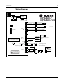
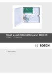
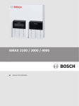
Wiring Diagram
3671
5 5
7
ICP-AMAX-P
ICP-AMAX-P-EN
7
:((3RUW
7DPSHU
6ZLWFK3RUW
3
Z8
1
3
COM
Z7
3
Z6
,QVWDOODWLRQ&RGH5HVWRUH
2
1 Tamper Switch
2 Zone Switch
3 EOL 2,2 k
2
COM
Z5
=RQH
,&3(=3.
3URJUDP.H\3RUW
3
Z4
2
COM
Z3
Z2
COM
Z1
,&3$0$;/&'
,&3$0$;/('
Y
)DVW᧶'LDOOLQJLQGLFDWLRQDQGSRZHU
RQWRUHVWRUHLQVWDOODWLRQFRGH
6ORZ1RUPDORSHUDWLRQLQGLFDWLRQ
%RVFK
%XV
OC32XWSXW
OC+3RUW
PD[LPXPRXWSXWFXUUHQW
2&9'&#P$
GND
+12V
)RURSHUDWLRQVDIHW\
WKHJURXQGWHUPLQDOV
PXVWEHFRQQHFWHG
_
OC1
_
OC+
+
+
%DWWHU\
AC
AC
Robert Bosch Engineering and Business Solutions Limited
9$	$
+
PD[LPXPRXWSXWFXUUHQW᧶
2&9'&#P$
2&9'&#P$
9$K
7UDQVIRUPHU
3RZHU
';
PD[RXWSXW
FXUUHQWP$
OC2
-
5HIHUWRUHODWHG8VHU0DQXDOIRU
';%,76';*
';
';%
,76';*
B
R
$X[
3RZHU
/('
G
Keypad 1
Keypad 2
1
1
/
/
5LVNRIVKRFNLI1/
RULVFRQQHFWHG
LQFRUUHFWO\
Fuse 500 mA
9a+]
P$
F.01U.241.128 | V2 | 2011.11
4
F.01U.241.128 | V2 | 2011.11
F.01U.241.128
Robert Bosch Engineering and Business Solutions Limited
AMAX panel 2000 / AMAX panel 2000 EN
Table of Contents | en
5
Table of Contents
1
Summary
7
1.1
Introduction
7
1.2
Installation
7
1.3
Programming
7
1.4
Quick start
7
1.5
Using the keyboard for programming
8
1.6
Setting date and time
9
1.7
System installer password reset
9
2
User and Installer Code Functions
10
3
Fault and Tamper Description
11
4
Programming sheets
13
4.1
Receiver programming
13
4.1.1
Receiver parameters
13
4.1.2
Domestic programming
14
4.2
System Report Options Programming
14
4.2.1
Report Options
14
4.2.2
Test Report Time Interval Setting
15
4.3
System Functions Programming
15
4.3.1
Ring Count
15
4.3.2
Remote Programming/Control
15
4.3.3
Call back Telephone Number
15
4.3.4
Exit Time
15
4.3.5
Entry Time
15
4.3.6
Keypad Lockout
16
4.3.7
Single Button STAY/AWAY ARM
16
4.3.8
Remote Arm by Software/Telephone
16
4.3.9
Arm by Keyfob
16
4.3.10
Force Arm as system is in trouble
16
4.3.11
Quick Emergency Alarm
16
4.3.12
Event Recall
16
4.3.13
OC1/Warning Device 1 Monitor
16
4.3.14
OC2/Warning Device 2 Monitor
16
4.3.15
Phone line Monitor
16
4.3.16
AC Fault Detect time
17
4.3.17
Battery Detect time
17
4.3.18
Event Record Count Per Set/Unset Period
17
4.3.19
Beep for Warning Devices
17
4.4
Zone Programming
17
4.5
Output Programming
20
4.5.1
Keypad Buzzer
20
4.5.2
Warning Device 1/ OC1 Output
20
4.5.3
Warning Device 2 / OC2 Output
20
4.5.4
Optional Relay Output / OC3
20
Robert Bosch Engineering and Business Solutions LimitedQuick Reference Guide
F.01U.241.128 | V2 | 2011.11
6
en | Table of Contents
AMAX panel 2000 / AMAX panel 2000 EN
4.5.5
DX3010 Output
20
4.6
Installer/User Code Programming
22
4.6.1
Installer code #0
22
4.6.2
User Codes
22
5
Specification
24
6
FAQs
26
Glossary
28
Index
29
F.01U.241.128 | V2 | 2011.11
Quick Reference Guide
Robert Bosch Engineering and Business Solutions
AMAX panel 2000 / AMAX panel 2000 EN
1
Summary
1.1
Introduction
Summary | en
7
Thank you for choosing the AMAX Panel 2000/ AMAX Panel 2000 EN alarm host. This is a
flexible, reliable, convenien, and easy-to-use alarm system. This Quick reference guide is
provided with the system to give basic information about the basic system wiring,
components, and programming. As the system includes a large number of programmable
functions and options, we suggest reading the complete installation instructions. The
instructions introduce the system options, functions, and programming methods in detail.
1.2
Installation
This system must be installed by a qualified installer (please refer to installation
instructions).
During installation and wiring, the alarm host power source must be switched-off to prevent
equipment damage.After the alarm host wiring is completed, connect the AC power and
backup batteries (*backup batteries must be connected).The power light on the keyboard will
flash to show that the AC power is connected.
1.3
Programming
The programming and selections of this system are stored in non-volatile memory. Even when
the electricity is totally disconnected, this memory retains all information, and this
information can be modified many times if required.
1.4
Quick start
The following steps allow you to use the AMAX Panel 2000/AMAX Panel 2000 EN with factory
default values. To become familiar with programming AMAX Panel 2000/AMAX Panel 2000 EN,
read the information in.
1.
2.
Connect auxiliary equipment
After all wiring is complete, connect the AC plug pack and backup battery to the control
panel. The MAINS indicator lights signify AC mains supply is connected.
If any zone is unsealed when you power up the system, the corresponding zone indicator
is lit constantly.
Once you power up the panel, Date and Time has to be set.
All Faults and Tamper conditions have to be reset.
3.
Enter the default user code (2580) + (98) and press [#] to enable the installer’s access.
4.
Enter Date and Time. Refer to Section 1.6 Setting date and time on Page 9.
5.
Enter the default Installer Code (1234) + (958) and press [#]. Two beeps sound and the
STAY and AWAY indicators flash simultaneously to indicate that you have entered into
installer’s programming mode. Once you enter the installer’s programming mode, you are
automatically positioned at location 000, the first digit of IP address / Primary telephone
number for Receiver 1.
6.
Enter the IP address/Primary telephone number for Receiver 1 and then the port.
Programming a 15 in the telephone number indicates the end of the dialing sequence.
7.
8.
Program any other required changes. Otherwise, factory default settings are used.
Enter command [9 6 0] and press [#] to store the programming data and exit from
installer’s programming mode, a beep sounds and the STAY and AWAY indicators are
deactivated. The system is returned to the disarmed state and is ready for use.
Robert Bosch Engineering and Business Solutions LimitedQuick Reference Guide
F.01U.241.128 | V2 | 2011.11
8
en | Summary
AMAX panel 2000 / AMAX panel 2000 EN
9.
1.5
Enter the default user code (2580) and (6) and press [#] to reset the panel.
Using the keyboard for programming
The system must be disarmed (no alarms) for programming. If there are alarms or the system
is armed, please enter the user code for user code 1 (confirmation 2580), then press the [#]
key (user code 1 is the factory preset user).
To enter installation and programming mode, please enter the installer password
(confirmation 1234), then press the [#] key. It will beep twice, and the "STAY" and "AWAY"
lights will flash simultaneously. This shows that programming mode has been activated. The
keyboard indicator shows the programming data at address 000 (main telephone initial
location).
To move to another programming location, please enter the address number, and press the
[#] key. The data in the new address will be shown on the keyboard indicator (for example, if
you enter [17#], the system will move to address 017, and this is the starting location of the
receiver 1 subscriber identity).
To move to the next address, please press the [#] key. This will take you to the next location.
The data in the next address will be shown on the keyboard indicator (for example, if your
present location is 017, press the [#] key to take you to the next address, 018).
To go back one address, please press the [*] key (for example, if your present location is
location 018, pressing the [*] key will take you back to address 017).
To change the data in the current address, please enter the new value (0–15), then press the
[*] key. This will store the new data to this address (for example, if you enter the value [14*],
the defense area 4 indicator and "power" indicator will illuminate showing that the new data
value is 14).
To move to the next address, please press the [#] key. The data in the next address will be
shown.
To save system programming data and leave installation mode, please enter [960#].The
"STAY" and "AWAY" lights will go out. Save system programming data and returns to disarmed
mode.
To return to installation mode without saving system programming data, please enter
[959#].It will beep twice, the "STAY" and "AWAY" lights will go out. System programming data
is not saved and return to disarmed mode.
Quick programming instructions are shown in the following Table:
Tasks
Keyboard input
Enter installation mode
[1 2 3 4 #]
Enter next address
[#]
Return to previous address
[*]
Set new data in address
[Data][*]
(Data range:0–15)
Jump to other address
[Address
number][#]
* Return to installation programming mode without saving system data [9 5 9 #]
* Save system data and return to installation programming mode
Table 1.1
F.01U.241.128 | V2 | 2011.11
[9 6 0 #]
Quick Programming Instructions
Quick Reference Guide
Robert Bosch Engineering and Business Solutions
AMAX panel 2000 / AMAX panel 2000 EN
Summary | en
9
Keyboard indicator light
Date
Area 1
Area 2
Area 3
Area 4
Area 5
Area 6
Area 7
Area 8
Power
Value indicat
indicat
indicat
indicat
indicat
indicat
indicat
indicat
source
or light
or light
or light
or light
or light
or light
or light
or light
indicator
light
0
1
X
2
X
3
X
4
X
5
X
6
X
7
X
8
9
X
X
X
10
11
X
X
12
X
X
13
X
X
14
X
X
15
1.6
X
X
X
Setting date and time
This function allows the installer code holder to set or view the date and time
1.
Enter your installer code +955 and press [#]. Two beeps sound, the STAY and AWAY
indicators flash and date + time is shown in the format YYMMDD HHMM.
2.
Enter the year, month, day, hour and minute in YY, MM, DD, HH, MM format and press [#].
Use 24:00 hour format when programming the hour of the day. Beep sound and the
STAYand AWAY indicators are deactivated. If a long beep sounds, it indicates an
erroneous entry of date and time.
3.
If operation is not carried out within 240 seconds after entering the date and time
setting interface, the system will automatically exit from the setting.
Example
To set the date and time for the 25th of December 2010 at 10:30PM, enter:
[Installer code + 955][#] break until time is shown [1 0 1 2 2 5 2 2 3 0][#]
1.7
System installer password reset
This system can restore the password to factory settings using the password reset:
1.
2.
Disconnect the AC power and backup battery from the alarm host.
Short circuit reset key (reset key is on the upper right corner next to the programmer
key).
3.
Connect the AC power to the alarm host.
4.
Wait until the LED light on the host PCB flashes rapidly, then release the reset key.
5.
The alarm host installer password has now been reset to the factory settings. Other
programming parameters have not changed.
Robert Bosch Engineering and Business Solutions LimitedQuick Reference Guide
F.01U.241.128 | V2 | 2011.11
10
2
en | User and Installer Code Functions
AMAX panel 2000 / AMAX panel 2000 EN
User and Installer Code Functions
User
Install
Code
er
Function
Description
Code
•
•
0
#
Duress alarm
•
•
1
#
Siren test
•
•
2
#
Fault and Tamper analysis
•
•
3
#
View date and time
•
•
4
#
Walk test
•
•
5
#
Event memory recall
•
•
6
#
Reset panel/clear siren
•
•
7
#
Initiate a modem call
•
•
8
#
Send Test report
•
•
9
#
Bypass (inhibit)
•
•
96
#
Show Zone type
•
97
#
Overide all faults
•
98
#
Enable=# / Disable=* installer code user's access
*
•
•
99
#
Change individual code
•
955
#
Change/View date and time
•
956
#
Add/delete a level 2 user
•
956
#
Add/delete Remote Radio User Codes
•
957
#
Change domestic phone numbers
•
958
#
Enter Programming Mode
•
959
#
Exits from installer’s programming mode without saving
the programmed data.
•
960
#
Exits from installer’s programming mode with saving the
programmed data.
•
961
#
Resets the control panel to factory defaults.
•
962
#
Copies the control panel memory to the programming key.
•
963
#
Copies the programming key data to the control panel
memory.
•
999
#
Displays the software version number or control panel
type.
Default Pads on PCB
Default the control panel with the hardware
NOTICE!
Installer code is only active when enabled from user.
F.01U.241.128 | V2 | 2011.11
Quick Reference Guide
Robert Bosch Engineering and Business Solutions
AMAX panel 2000 / AMAX panel 2000 EN
3
Fault and Tamper Description | en
11
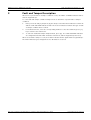
Fault and Tamper Description
Whenever a system fault or a tamper condition occurs, the FAULT or MAINS indicator flashes
and the keypad beeps.
To enter fault and tamper condition analysis mode to determine a system fault or tamper
condition:
1.
Enter your Code and [2] and press [#] two beeps sound.The FAULT indicator remains lit
and the STAY and AWAY indicators flash. The lit zone indicators indicate the type of fault
or tamper condition that occurred.
2.
For multi-level menu, enter the corresponding number to enter the submenu, press [ 0 ]
key to return to the main menu.
3.
To exit from Fault and Tamper Analysis Mode, press [#] . The STAY and AWAY indicators
are extinguished and the FAULT indicator remains lit, and the keypad stops the beep.
When a new fault or tamper occurs, the FAULT indicator flashes again and the keypad beeps.
The FAULT indicator gets extinguished once all faults are restored.
Robert Bosch Engineering and Business Solutions LimitedQuick Reference Guide
F.01U.241.128 | V2 | 2011.11
12
en | Fault and Tamper Description
AMAX panel 2000 / AMAX panel 2000 EN
Zone Indicator
1
2
3
Accessory Modules Fail
1
Keypad 1 fail
2
Keypad 2 fail
3
DX 3010 Fail
4
B420/DX 4020 /-G Fail
Power Faults
1
AC Fault
2
Fault Battery
3
Aux Power Supply Fault
4
Bosch Option Bus Power Fault
5
RF Power Fault
Warning Device Failure List
1
Warning Device 1 Disconnected
2
Warning Device 1 Short
3
Warning Device 2 Disconnected
4
Warning Device 2 Short
4
Telephone Line Fail
5
Date and Time Fail
6
Communications failure
7
8
F.01U.241.128 | V2 | 2011.11
1
Communication Failure 1
2
Communication Failure 2
3
Communication Failure 3
4
Communication Failure 4
Tamper
1
On board Tamper
2
Keypad 1 Tamper
3
Keypad 2 Tamper
4
Keypad Lock out
5
Sensor Tamper (Zone 1-8)
6
Tamper Zone (Zone 1-8)
External Fault
Quick Reference Guide
Robert Bosch Engineering and Business Solutions
AMAX panel 2000 / AMAX panel 2000 EN
4
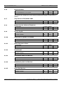
Programming sheets
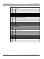
4.1
Receiver programming
4.1.1
Receiver parameters
Programming sheets | en
Report Options
Location Default
Telephone Number/IP Address and Port for Receiver 1
000-016
15
Subscriber ID Number for Receiver 1
017-022
000000
Transmission Format for Receiver 1(0=Not used, 1=Contact
023
1 EN=1
024
1
Acknowledge Wait Time for Receiver 1 (05 – 99 seconds)
025-026
05
Pulse Interval Time for Receiver 1(001 – 999 Minutes)
027-029
001
Telephone Number/IP Address and Port for Receiver 2
030-046
15
Subscriber ID Number for Receiver 2
047-052
000000
Transmission Format for Receiver 2(0=Not used, 1=Contact
053
1
054
1
Acknowledge Wait Time for Receiver 2 (05 – 99 seconds)
055-056
05
Pulse Interval Time for Receiver 2(001 – 999 Minutes)
057-059
001
Telephone Number/IP Address and Port for Receiver 3
060-076
15
Subscriber ID Number for Receiver 3
077-082
000000
Transmission Format for Receiver 3
083
1
084
1
Acknowledge Wait Time for Receiver 3 (05 – 99 seconds)
085-086
05
Pulse Interval Time for Receiver 3 (001 – 999 Minutes)
087-089
001
Telephone Number/IP Address and Port for Receiver 4
090-106
15
Subscriber ID Number for Receiver 4
107-112
000000
Transmission Format for Receiver 4
113
1
114
1
Acknowledge Wait Time for Receiver 4 (05 – 99 seconds)
115-116
05
Pulse Interval Time for Receiver 4
117-119
001
13
ID, 2=CFSK, 3=Bosch Network)
Anti-replay for Receiver 1
0=Disable,1=Enable
ID, 2=CFSK, 3=Bosch Network)
Anti-replay for Receiver 2
0=Disable, 1=Enable
(0=Not used, 1=Contact ID, 2=CFSK, 3=Bosch Network)
Anti-replay for Receiver 3
0=Disable, 1=Enable
(0=Not used, 1=Contact ID, 2=CFSK, 3=Bosch Network)
Anti-replay for Receiver 4
0=Disable, 1=Enable
(001 – 999 Minutes)
–
IP address is programmed as 17 digits data code. Digit 1-12 is for receiver IP address,
digit 13~17 is for communication port.
The dot does not need to be programmed. The IP address is combined by 4 units, each unit
has 3 digits. If any unit is less than 3 digits, use 0 to fulfill the data in the higher bits. If the
port number is less than 5 digits, use 0 to fulfill the data in the higher bits.
Robert Bosch Engineering and Business Solutions LimitedQuick Reference Guide
F.01U.241.128 | V2 | 2011.11
14
en | Programming sheets
AMAX panel 2000 / AMAX panel 2000 EN
Example: For IP Address for receiver 128.73.168.7, communication port 7700, program as:
128 073 168 007 07700
NOTICE!
Programming option anti-replay, acknowledge wait time and pulse interval time are only used
in Bosch network format.
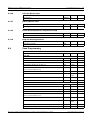
4.1.2
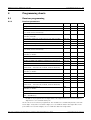
4.2
Domestic programming
Address
120–135
Preset values
15 (if the first digit input is 15 this function is prohibited)
Digit
Program input keys
Digit
Program input keys
0
0
8
8
1
1
9
9
2
2
*
11
3
3
#
12
4
4
Wait 4 seconds
13
5
5
15
15
6
6
7
7
System Report Options Programming
System sends reports to Receiver 1-4 according to system status report options. The
locations for the reports are 137-144.
4.2.1
Report Options
Location 137-144
Location Default
Zone Restore Report Options (Alarm restore, fault restore,
137
0
Arm/Disarm report option in AWAY Mode
138
6
Arm/Disarm report option in STAY Mode
139
6
System Status Report Options (Zone fail, comm. fail,
140
6 EN=1/
bypass restore)
telephone line fail, AC fail, low battery...etc.)
5/6/7
Keypad panic report
141
0
Keypad fire report
142
0
Keypad medical report
143
0
Test report options
144
6 EN=1/
5/6/7
Zone Status Reporting Options
0
No zone status report allowed
1
Report to Receiver 1
2
Report to Receiver 2
3
Report to Receiver 3
4
Report to Receiver 4
F.01U.241.128 | V2 | 2011.11
Quick Reference Guide
Robert Bosch Engineering and Business Solutions
AMAX panel 2000 / AMAX panel 2000 EN
Programming sheets | en
15
Zone Status Reporting Options
5
Report to Receiver 1,2,3,4
6
Report to destination 1 (2,3,4 backup)
7
Report to destination 1 (2 backup) and destination 3 (4 backup)
NOTICE!
The system sends no report when programmed to report to the receiver as Option 0.
4.2.2
Test Report Time Interval Setting
Location 145-150
Default
145-146=timer test report(1-99 hours)0=don’t send timer
24 EN=1-24
test report
147-148=Report time: Hours=0-23(else=don’t send real time
99
test report)
149-150=Report time: minutes=0~59(else=don’t send real
99
time test report)
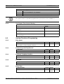
4.3
System Functions Programming
4.3.1
Ring Count
Location 152
Location Default
0=Panel does not answer
152
0
1–15= Number of rings until panel answers
4.3.2
4.3.3
4.3.4
4.3.5
Remote Programming/Control
Location 153
Location Default
0=Disable 1=Enable
153
1
Call back Telephone Number
Location 154-169
Location Default
15 = telephone termination
154-169
15
Exit Time
Location 170-172
Location Default
000-255 seconds
170-172
045
Entry Time
Location 173-175
Location Default
000-255 seconds
173-175
045
EN=45
Robert Bosch Engineering and Business Solutions LimitedQuick Reference Guide
F.01U.241.128 | V2 | 2011.11
16
en | Programming sheets
4.3.6
AMAX panel 2000 / AMAX panel 2000 EN
Keypad Lockout
Location 179
Location Default
1 - 15= attempt times 0=no lockout
179
6 EN=10
If an invalid code attempts more times than programmed, the keypad is locked out for 3
minutes.
4.3.7
4.3.8
4.3.9
4.3.10
4.3.11
4.3.12
4.3.13
4.3.14
4.3.15
Single Button STAY/AWAY ARM
Location 180
Location Default
0=Disable 1=Enable
180
1 EN=0
Remote Arm by Software/Telephone
Location 181
Location Default
0=Disable 1=Enable
181
1 EN=0
Arm by Keyfob
Location 182
Location Default
0=Disable 1=Enable
182
1 EN=0
Force Arm as system is in trouble
Location 183
Location Default
0=Disable 1=Enable
183
1 EN=0
Quick Emergency Alarm
Location 184
Location Default
0=Disable 1=Enable
184
1
Event Recall
Location 182
Location Default
0=Disable 1=Enable
185
1
OC1/Warning Device 1 Monitor
Location 186
Location Default
0=Disable 1=Enable
186
0 EN=1
OC2/Warning Device 2 Monitor
Location 187
Location Default
0=Disable 1=Enable
187
0 EN=1
Phone line Monitor
Location 188
Location Default
0=Disable 1=Enable
188
F.01U.241.128 | V2 | 2011.11
Quick Reference Guide
0 EN=1
Robert Bosch Engineering and Business Solutions
AMAX panel 2000 / AMAX panel 2000 EN
4.3.16
4.3.17
4.3.18
4.3.19
4.4
Programming sheets | en
17
AC Fault Detect time
Location 189-190
Location Default
0-60 Minutes
189-190
10
Battery Detect time
Location 191
Location Default
1-15 min
191
1 EN=15
Event Record Count Per Set/Unset Period
Location 192
Location Default
3-10
192
3
Beep for Warning Devices
Location 193
Location Default
0=Disable 1=Enable
193
0
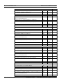
Zone Programming
Location 210-289
Zone
Location Default
Zone #01
Zone Type (Refer to zone type option)
210
3
Zone Bypass (Disable=0, Enable=1)
211
1
Forced Arming (Disable=0, Enable=1)
212
1 EN=0
Silent Alarm (Enable=1, Disable=0)
213
0 EN=0
Zone alarm lock out time (Disable=0, 1 times=1, 3 times=2, 6
214
0
Support Detector Tamper (Disable=0, Enable=1)
215
1
Zone alarm report (Refer to zone report option)
216
6 EN=1/
times=3, alarm duration=4)
5/6/7
Zone Chime Mode (Enable=1, Disable=0)
217
0
Reserved
218-219
0
Zone Type (Refer to zone type option)
220
1
Zone Bypass (Disable=0, Enable=1)
221
1
Zone #02
Forced Arming (Disable=0, Enable=1)
222
1 EN=0
Silent Alarm (Enable=1, Disable=0)
223
0 EN=0
Zone alarm lock out time (disable=0, 1 times=1, 3 times=2, 6
224
0
Support Detector Tamper (Disable=0, Enable=1)
225
1
Zone alarm report (Refer to zone report option)
226
times=3, alarm duration=3)
6 EN=1/
5/6/7
Zone Chime Mode (Enable=1, Disable=0)
227
0
Reserved
228-229
0
Robert Bosch Engineering and Business Solutions LimitedQuick Reference Guide
F.01U.241.128 | V2 | 2011.11
18
en | Programming sheets
AMAX panel 2000 / AMAX panel 2000 EN
Zone #03
Zone Type (Refer to zone type option)
230
1
Zone Bypass (Disable=0, Enable=1)
231
1
Forced Arming (Disable=0, Enable=1)
232
1 EN=0
Silent Alarm (Enable=1, Disable=0)
233
0 EN=0
Zone alarm lock out time (disable=0, 1 times=1, 3 times=2, 6
234
0 EN=4
Support Detector Tamper (Disable=0, Enable=1)
235
1
Zone alarm report (Refer to zone report option)
236
6 EN=1/
times=3, alarm duration=4)
5/6/7
Zone Chime Mode (Enable=1, Disable=0)
237
0
Reserved
238-239
0
Zone Type (Refer to zone type option)
240
1
Zone Bypass (Disable=0, Enable=1)
241
1
Forced Arming (Disable=0, Enable=1)
242
1 EN=0
Silent Alarm (Enable=1, Disable=0)
243
0 EN=0
Zone alarm lock out time (disable=0, 1 times=1, 3 times=2, 6
244
0
Support Detector Tamper (Disable=0, Enable=1)
245
1
Zone alarm report (Refer to zone report option)
246
6 EN=1/
Zone #04
times=3, alarm duration=4)
5/6/7
Zone Chime Mode (Enable=1, Disable=0)
247
0
Reserved
248-249
0
Zone Type (Refer to zone type option)
250
1
Zone Bypass (Disable=0, Enable=1)
251
1
Forced Arming (Disable=0, Enable=1)
252
1 EN=0
Silent Alarm (Enable=1, Disable=0)
253
0 EN=0
Zone alarm lock out time (disable=0, 1 times=1, 3 times=2, 6
254
0
Support Detector Tamper (Disable=0, Enable=1)
255
1
Zone alarm report (Refer to zone report option)
256
6 EN=1/
Zone #05
times=3, alarm duration=4)
5/6/7
Zone Chime Mode (Enable=1, Disable=0)
257
0
Reserved
258-259
0
Zone Type (Refer to zone type option)
260
1
Zone Bypass (Disable=0, Enable=1))
261
1
Forced Arming (Disable=0, Enable=1)
262
1 EN=0
Silent Alarm (Enable=1, Disable=0)
263
0 EN=0
Zone alarm lock out time (disable=0, 1 times=1, 3 times=2, 6
264
0
265
1
Zone #06
times=3, alarm duration=4)
Support Detector Tamper (Disable=0, Enable=1)
F.01U.241.128 | V2 | 2011.11
Quick Reference Guide
Robert Bosch Engineering and Business Solutions
AMAX panel 2000 / AMAX panel 2000 EN
Programming sheets | en
Zone alarm report (Refer to zone report option)
266
19
6 EN=1/
5/6/7
Zone Chime Mode (Enable=1, Disable=0)
267
0
Reserved
268-269
0
Zone Type (Refer to zone type option)
270
1
Zone Bypass (Disable=0, Enable=1)
271
1
Forced Arming (Disable=0, Eanble=1)
272
1 EN=0
Silent Alarm (Enable=1, Disable=0)
273
0 EN=0
Zone alarm lock out time (disable=0, 1 times=1, 3 times=2, 6
274
0
Support Detector Tamper (Disable=0, Enable=1)
275
1
Zone alarm report(Refer to zone report option)
276
6 EN=1/
Zone #07
times=3, alarm duration=4)
5/6/7
Zone Chime Mode (Enable=1, Disable=0)
277
0
Reserved
278-279
0
Zone Type (Refer to zone type option)
280
1
Zone Bypass (Disable=0, Enable=1)
281
1
Forced Arming (Disable=0, Enable=1)
282
1 EN=0
Silent Alarm (Enable=1, Disable=0)
283
0 EN=0
Zone alarm lock out time (Disable=0, 1 times=1, 3 times=2, 6
284
0
Support Detector Tamper (Disable=0, Enable=1)
285
1
Zone alarm report(Refer to zone report option)
286
Zone #08
times=3, alarm duration=4)
6 EN=1/
5/6/7
Zone Chime Mode (Enable=1, Disable=0)
287
0
Reserved
288-289
0
Zone Types
Zone Type
Description
0
Zone not used
1
Instant
2
Interior Instant
3
Delay
4
Interior Delay
5
Follower
6
Interior Follower
7
24-Hour
8
Tamper
9
Fire
10
External Fault
11
Bolt Contact
Robert Bosch Engineering and Business Solutions LimitedQuick Reference Guide
F.01U.241.128 | V2 | 2011.11
20
en | Programming sheets
AMAX panel 2000 / AMAX panel 2000 EN
Zone Type
Description
12
Key Switch Toggle
13
Key Switch on/off
4.5
Output Programming
4.5.1
Keypad Buzzer
4.5.2
Location 370
Location Default
Keypad beeps when siren on 1=Disable, 1=Enable
370
0
Warning Device 1/ OC1 Output
Output 1
Location Default
Event Type (fixed value)
3 EN
Polarity Mode (0=Steady, 1=Pulse)
371
0 EN=0
Output Duration (001-999sec/000=on)
372-374
000
EN=180
NOTICE!
When the triggered zone is programmed as silent zone, keypad output and OC1 output do not
response. Other outputs are as normal.
4.5.3
Warning Device 2 / OC2 Output
Output 2
Location Default
Event Type (Refer to output events option)
375
3 EN=3
Polarity Mode (0=Steady, 1=Pulse)
376
0 EN=0
Output Duration (001-999sec/000=on)
377-379
000
EN=180
4.5.4
Optional Relay Output / OC3
Optional Relay Output
4.5.5
Event Type (Refer to output events option)
380
0
Polarity Mode (0=Steady, 1=Pulse)
381
0
Output Duration (001-999sec/000=on)
382-384
030
DX3010 Output
Location
Location Default
Relay Output 1
Event Type (Refer to output events option)
385
0
Polarity Mode (0=Steady, 1=Pulse)
386
0
Output Duration (001-999sec/000=on)
387-389
030
Event Type (Refer to output events option)
390
0
Polarity Mode (0=Steady, 1=Pulse)
391
0
Output Duration (001-999sec/000=on)
392-394
030
Relay Output 2
F.01U.241.128 | V2 | 2011.11
Quick Reference Guide
Robert Bosch Engineering and Business Solutions
AMAX panel 2000 / AMAX panel 2000 EN
Programming sheets | en
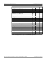
21
Relay Output 3
Event Type (Refer to output events option)
395
0
Polarity Mode (0=Steady, 1=Pulse)
396
0
Output Duration (001-999sec/000=on)
397-399
030
Event Type (Refer to output events option)
400
0
Polarity Mode (0=Steady, 1=Pulse)
401
0
Output Duration (001-999sec/000=on)
402-404
030
Event Type (Refer to output events option)
405
0
Polarity Mode (0=Steady, 1=Pulse)
406
0
Output Duration (001-999sec/000=on)
407-409
030
Event Type (Refer to output events option)
410
0
Polarity Mode (0=Steady, 1=Pulse)
411
0
Output Duration (001-999sec/000=on)
412-414
030
Event Type (Refer to output events option)
415
0
Polarity Mode (0=Steady, 1=Pulse)
416
0
Output Duration (001-999sec/000=on)
417-419
030
Event Type (Refer to output events option)
420
0
Polarity Mode (0=Steady, 1=Pulse)
421
0
Output Duration (001-999sec/000=on)
422-424
030
Relay Output 4
Relay Output 5
Relay Output 6
Relay Output 7
Relay Output 8
Set all 8 event type options to 0 if you do not use DX3010 relay module.
Robert Bosch Engineering and Business Solutions LimitedQuick Reference Guide
F.01U.241.128 | V2 | 2011.11
22
en | Programming sheets
Event Type
Description
0
No output activate for the events
1
System Disarmed
2
System Armed
3
System Alarm
4
Entry/Exit Delay Warning
5
Telephone Line Fail
6
AC Lost
7
Battery Low
8
RF Power Fault
9
TAMPER
10
External Fault
11
All Faults
12
Away armed
13
Stay armed
14
Reset
15
24h Alarm
Table 4.1
4.6
AMAX panel 2000 / AMAX panel 2000 EN
Output Events Option
Installer/User Code Programming
Each installer/user code unit contains up to 4 digits. Each digit range is 0-9. Default first digit
as data 15 means Not Used. Other data are not permitted.
4.6.1
Installer code #0
Location 425-428
Location Default
425
1
426
2
427
3
428
4
Installer Code is used to program the system.
F.01U.241.128 | V2 | 2011.11
Quick Reference Guide
Robert Bosch Engineering and Business Solutions
AMAX panel 2000 / AMAX panel 2000 EN
4.6.2
Programming sheets | en
23
User Codes
Location 430-509
Location Default
User Code #01
430
2
431
5
432
8
433
0
User #02
435-438
15
User #03
440-444
15
User #04
445-449
15
User #05
450-454
15
User #06
455-459
15
User #07
460-464
15
User #08
465-469
15
RF User #09
470-474
15
EN=15
RF User #10
475-479
15
EN=15
RF User #11
480-484
15
EN=15
RF User #12
485-489
15
EN=15
RF User #13
490-494
15
EN=15
RF User #14
495-499
15
EN=15
RF User #15
500-504
15
EN=15
RF User #16
505-509
15
EN=15
Robert Bosch Engineering and Business Solutions LimitedQuick Reference Guide
F.01U.241.128 | V2 | 2011.11
24
5
en | Specification
AMAX panel 2000 / AMAX panel 2000 EN
Specification
Panel
Enclosure :
Dimensions (HxWxD):
–
Weight:
–
260mm x 280mm x 83,5mm
1950g
Environmental Considerations:
Relative Humidity:
–
10%-95%
Operating Temperature:
–
-10°C - +55°C
Supervised Zones:
Onboard:
Z1 - Z8 COM
–
8 Single or dual end-of-line (EOL 2,2KΩ) tamper point
support
P8 Tamper
–
Enclosure tamper input (does not reduce point capacity)
Programmable Outputs (PO):
Onboard:
OC 1
–
supervised output max 500mA
OC 2
–
supervised output max 500mA
P7 Relay output
–
max 100mA
Relay 1-8
–
Contacts rated 5A at 28VDC
Cable requirements:
–
Unshielded and shielded 0,6-0,8mm
Users:
–
16 (8 + 8Keyfob)
Key Fobs:
–
8
Events:
–
254 history events, stamped with time and date
–
254 EN history events, stamped with time and date
Pin Code variations
–
10000
DX 3010:
–
1
B 420 or DX 4020 or DX
–
1
–
2
Power Supply Type:
–
A
Transformer:
–
230V Input/18VAC 20VA Fuse=500mA
AC Input:
–
AC Input Voltage: 195 VAC to 253 VAC
–
Line Voltage Frequency: 50 Hz
–
maximum current for all components 1100mA
–
maximum current for all components 550mA (recharge Batt
Auxiliary module
(DX3010):
Number of...
40206
Keypads:
Power:
DC Output:
80% in 72h)
Aux (+12V/GND) Output:
–
Nominal Output Voltage under AC line input: 13,5 VDC +3%
/ -5%
F.01U.241.128 | V2 | 2011.11
Quick Reference Guide
Robert Bosch Engineering and Business Solutions
AMAX panel 2000 / AMAX panel 2000 EN
Specification | en
–
25
Output Voltage Range under AC line input: 12,82 VDC to
13,9 VDC
Option Bus:
–
500mA maximum
–
Vpp (max) 675mV
–
Nominal Output Voltage under AC line input: 13,5 VDC +3%
/ -5%
–
Output Voltage Range under AC line input: 12,82 VDC to
13,9 VDC
–
500mA maximum
RF Power Output
–
5VDC / 100mA maximum
Panel PCB
–
Quiescent current maximum 100mA
Battery:
–
D126 (12V/7 Ah) sealed, lead acid rechargeable
–
Low battery condition is below 11,8 VDC
–
Minimum battery condition is 10,8VDC
–
Maximum auxiliary current to recharge standby battery to
80% within 72h:
Certification:
–
12 V/7 Ah Battery: 550 mA
–
EN 50131-3 Grade-2 Env-II
Keypads:
IUI-AMAX-LED8 (8Zone LED Keypad)
Relative Humidity:
–
10%-95%
Operating Temperature:
–
-10°C - +55°C
Input Voltage range:
–
10VDC - 14VDC
Current Consumption
–
standby 24mA
–
Cable requirements:
EN type:
maximum 50mA
–
four wire, unshielded and shielded 0,6-0,8mm
–
maximum length 150m
–
B
IUI-AMAX-LCD8 (8Zone LCD Keypad)
Relative Humidity:
–
10%-95%
Operating Temperature:
–
-10°C - +55°C
Input Voltage range:
–
10VDC - 14VDC
Current Consumption
–
standby 18mA
–
Cable requirements:
EN type:
maximum 60mA
–
four wire, unshielded and shielded 0,6-0,8mm
–
maximum length 150m
–
B
Robert Bosch Engineering and Business Solutions LimitedQuick Reference Guide
F.01U.241.128 | V2 | 2011.11
26
6
en | FAQs
AMAX panel 2000 / AMAX panel 2000 EN
FAQs
Issues
Causes and solutions
After turning on the
–
In order to ensure regular operation, after power is turned on,
the system needs to stabilize for one minute
unit, there is no
response for a defense
zone monitor for a
short time.
After turning the unit
–
Check whether the AC power supply and battery fuse are
working correctly
on, the keyboard does
not show.
–
Check the keyboard main cable RBGY connection
Keyboard operation
–
Check the keyboard main cable RBGY connection
does not work
–
After many password input errors, the keyboard locks. Wait for
three minutes, and then try the operation again
(pressing any key
produces an error
–
If two keyboards are used, there is a jump error
sound).
–
If two keyboards are used, it is necessary to wait for 30
seconds before operating the other keyboard
After turning the unit
–
programming mode.
The system is in alarm status. If: the disarm switch and 24
hour defense zone are not ready
on, cannot enter
–
The system is alarmed. Programming mode must be set while
disarmed
Host LED status light
–
does not display.
If AC power source and backup batteries are not working
correctly; please check the power source
–
Motherboard is damaged. Please replace the motherboard
Defense zone light
–
Check whether the defense zone cable is correctly connected
stays illuminated.
–
Check whether the detector functions normally
–
The end of the defense zone line should be correctly
connected to the detector terminal
Error light stays lit/
–
Date and time are not set
flashes.
–
Battery is not connected or backup battery power is below 12
V
–
No alarm signal received. If the user does not connect the
alarm signal, a 1K resistance can be substituted
–
Telephone number is not set correctly
–
Telephone network is not connected
–
Disarm switch is not connected. If the user does not use the
disarm switch, it is necessary to connect the short circuit wire
–
Programming should be carried out using an external module,
in fact the external module is not connected, for example:
DX3010 CHI, DX4020 or DX4020G.For specific situations
consult the programming handbook
AC power fuse is burnt
–
Check the transfer 18 V connector is working normally
out.
Auxiliary power source
–
overcurrent protection.
Check the 12 V auxiliary power source connection is running
normally
–
Check that the auxiliary power supply equipment is not
exceeding the 900 mA motherboard maximum. If the maximum
is exceeded, peripheral equipment must use external power
F.01U.241.128 | V2 | 2011.11
Quick Reference Guide
Robert Bosch Engineering and Business Solutions
AMAX panel 2000 / AMAX panel 2000 EN
After an auxiliary
FAQs | en
–
27
Restart the AC power supply and battery
power source short
circuit, system cannot
be restored.
After changing the
–
is cleared
still shows.
When there is an
When the system is armed or every 4 hours, it checks the
battery, so it may be necessary to wait before the battery error
battery, a battery error
–
New batteries may require charging before they reach 12 V
–
Check whether the communications were programmed to
alarm, the system does
disable the dial function (telephone number and
not dial.
communication format must be programmed)
Cannot remotely alarm. –
Check whether this function has been programmed (address
152 cannot be 0)
Central software
–
Check whether this function has been programmed (address
152 and 153 cannot be 0)
cannot be remotely
programmed and
controlled.
Using PSTN/personal
–
telephone alarm the
communication is
occasionally incorrect.
The telephone network uses an extension system; it is
necessary to add a delayed dial
–
The telephone network also supports ADSL; system must be
connected after the ADSL wave filter
Robert Bosch Engineering and Business Solutions LimitedQuick Reference Guide
F.01U.241.128 | V2 | 2011.11
28
en | Glossary
AMAX panel 2000 / AMAX panel 2000 EN
Glossary
A
Alarm
Event that is configured as an alarm. This is a particular situation (motion detected, doorbell
rung, signal lost, etc.) that requires immediate attention. An alarm can include live video,
playback video, an action plan, or a map.
F.01U.241.128 | V2 | 2011.11
Quick Reference Guide
Robert Bosch Engineering and Business Solutions
AMAX panel 2000 / AMAX panel 2000 EN
Index | en
29
Index
Robert Bosch Engineering and Business Solutions LimitedQuick Reference Guide
F.01U.241.128 | V2 | 2011.11
30
en | Index
F.01U.241.128 | V2 | 2011.11
AMAX panel 2000 / AMAX panel 2000 EN
Quick Reference Guide
Robert Bosch Engineering and Business Solutions
Robert Bosch Engineering and Business Solutions Limited
123, Industrial Layout, Hosur Road
560095 Banglore
India
www.bosch.com
© Robert Bosch Engineering and Business Solutions Limited, 2011