1
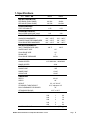
Rev.2.01B
www.cmadishmachines.com
Table of Contents
EST-44
1.
SPECIFICATIONS................................................................................................. 2
1.1.
2.
EST- 44........................................................................................................................................... 2
GETTING STARTED ............................................................................................ 3
2.1.
Introduction to EST -44.................................................................................................................. 3
2.2.
Receiving and Installation .............................................................................................................. 4
2.2.1.
Electrical ................................................................................................................................ 5
2.2.2.
Plumbing*............................................................................................................................... 5
2.2.3.
Installation Notes.................................................................................................................... 5
2.2.4.
Optional Table Limit Switch................................................................................................... 7
2.2.5.
Scrap Tray Assembly Installation ........................................................................................... 8
2.2.6.
Pump Impeller Note................................................................................................................ 9
2.2.7.
Optional Hood Adapter (Set of Two).................................................................................... 10
2.2.8.
Field Installed Accessories ................................................................................................... 11
2.2.8.1.
Chemical Dispensers .................................................................................................... 11
2.2.8.2.
Hood Fan Motor ........................................................................................................... 11
2.2.9.
EST-44 Heaters..................................................................................................................... 11
2.3. Safety Tips for the EST-44 ........................................................................................................... 13
3.
OPERATION ........................................................................................................ 14
3.1.
Initial Setup .................................................................................................................................. 14
3.1.1.
Rinse Pressure Regulator ..................................................................................................... 14
3.1.2.
Wash and Rinse Temperatures ............................................................................................. 14
3.2. Beginning Operation..................................................................................................................... 15
3.2.1.
Chemical Dispensing ............................................................................................................ 16
3.2.1.1.
Low Temperature Applications .................................................................................... 17
3.3. Regular Service and Maintenance Checklist ................................................................................ 17
3.4.
Trouble Shooting .......................................................................................................................... 19
4.
EST-44 CUSTOMER NOTICE .............................................................................. 20
5.
ELECTRICAL DIAGRAM FOR 230V EST-44................................................ 22
6.
ELECTRICAL DIAGRAM FOR E-TEMP HEATER ONLY......................... 23
7.
ELECTRICAL DIAGRAM FOR 480V EST-44................................................ 24
www.cmadishmachines.com
1. Specifications
1.1. EST- 44
EST-44
L.T.
WATER CONSUMPTION
EST-44
H.T.
PER RACK (FINAL RINSE)
.49 GAL.
.49GAL.
PER HOUR (FINAL RINSE)
119 GAL.
119 GAL.
6.75
6.75
243
243
WASH RECOMMENDED
140° - 150° F
150° - 160° F
PUMPED RINSE RECOMMENDED
140° - 150° F
150° - 160° F
FINAL RINSE RECOMMENDED
140° - 150° F
180° - 195° F
140° F
180° F
CONVEYOR SPEED
FEET PER MINUTE
OPERATING CAPACITY
RACKS PER HOUR (NSF rated)
OPERATING TEMPERATURE
WATER REQUIREMENTS
INLET TEMPERATURE (MIN)
WATER INLET SIZE
1/2”
FINAL RINSE SIZE
1/2”
DRAIN SIZE
2”
FINAL RINSE PRESSURE
20 PSI
HEATERS
WASH HEATER
12.75 KW/240V, 10KW/208V
RINSE HEATER
3KW
MOTORS
WASH PUMP
1 HP
RINSE PUMP
1/3 HP
CONVEYOR
1/8 HP
DIMENSIONS
DEPTH
25-1/8”
WIDTH
44”
HEIGHT
55 -1/2”-56-1/2”
STANDARD TABLE HEIGHT
32 ½” adjusts to 34”
MAX CLEARANCE FOR DISHES
19”
STRANDARD RACKS
ELECTRICAL RATING
19 ¾” x 19 ¾”
VOLTS
PHASE
AMPS
208
1
69
240
1
76
208
3
46
240
3
51
480
3
24
SHIPPING WEIGHT
MODEL EST-44 Installation and Operation Manual Rev. 2 .01B
662#
(300kg)
Page
2
Getting Started
2. Getting Started
2.1.
Introduction to EST -44
The EST is designed to give maximum cleaning in 44 inches. It represents the cleaning power of
machines twice its length. The curtains incorporated in the machine minimize transfer from tank
to tank during the wash and sanitizing procedures.
Energy costs for running the EST-44 have been greatly reduced by the introduction of stage
washing. EST (energy star) models lower gal/rack ratings are related to new washing stages
being introduced: wash/recirculating rinse/final rinse. EST models have one tank for wash water
and one tank for pumped rinse water, followed by a final rinse sanitizing rinse.
The supply water to the EST-44L must be a minimum of 140°F, while the EST-44H requires two
supply lines; one at a minimum water temperature of 180°F (for RINSE), and the other at a
minimum temperature of 140° F (for FILL).
The EST-44 features a scrap tray that may be emptied on a periodic basis without interruption of
the flow of work and the manner in which the tank is filled ensures that the dishes are always
rinsed with fresh water instead of re-circulated water. The EST machine is designed to deliver
0.49 gallons of fresh rinse water for each rack. This water flows from the rinse and pre-rinse tank
into the wash tank and then overflows into the scrap tray carrying debris with it, thereby providing
a much cleaner environment for the wash and rinse cycles.
There are also enhancements that can be chosen when desired such as optional Vent Hood
Adaptors and other machine accessories such as stainless steel dish tables.
MODEL EST-44 Installation and Operation Manual Rev. 2 .01B
Page 3
Getting Started
2.2.
Receiving and Installation
When you receive your new EST-44, complete the assembly by installing the scrap tray assembly
with its overflow chute, the two wrapper shields and the curtain rods, which are shipped inside the
machine. After the box has been removed from the machine, remove the left and right stainless
steel wrapper shields and bolt them in place with the nuts and bolts provided. The wrapper shield
with the extra curtain clamps mounts onto the dirty end of the machine. Next, mount the scrap
tray assembly and overflow chute into position (see section 2.2.5 Scrap Tray Assembly ).
All of the spray arms should be inserted and in place over the wash tank compartments.
There are a total of three curtains used in the EST-44; two are long- narrow, one is short- wide.
The two long-narrow curtains have shorter rods than the other two curtains. The short rods hold
the curtains at the entrance and exit of the machine.
The sketch below lists curtain positions 1 through 3.
EST-44
2
3
1
SHORTWIDE
CURTAINS
LONG-NARROW
CURTAIN
LONG-NARROW
CURTAIN
DISH FLOW
DISHMACHINE FRONT VIEW
MODEL EST-44 Installation and Operation Manual Rev. 2 .01B
Page
4
Getting Started
2.2.1. Electrical *
A 3-phase 208-240 volt AC, 60 Hz dedicated circuit should be used to supply electrical energy to
the EST-44 dishwasher (see specification sheet page 2). Connect the wire that has the
highest voltage (stinger lead) to the main contactor’s power terminal L2. Power lead wires
(L1, L2 and L3) used for the EST-44 at installation must comply with all local and State electrical
codes.
2.2.2. Plumbing*
The water supply connection is made with a ½” hot water line to the water supply inlet on the top
of the machine. The water supplied to the machine must be a minimum of 140° F for the EST44L and a minimum of 180° F for the EST-44H.
NOTES:
1. The Low Temp machine (EST-44L) can be supplied with single point water inlet kit with
braided hose included for fill and final rinse inlets connection.
2. The High Temp machine (EST-44H) comes with two water supply line connections. One
for the final rinse at 180° F and the second line is to fill the wash tank with 140° F —the
water will be heated to the appropriate temperature by the wash tank heater. (See
specification sheet on page 2).
There are two 2” drain connections to be made. One connection is made at either end of the
horizontal drainpipe coming from the wash tank and the other connection is made at the scrap
tray drain. (Instructions for installing the scrap tray assembly are provided in section 2.2.5 Scrap
Tray Assembly .) One of the ends of the horizontal drainpipe has a cap on it – simply move the
cap to the other end if it’s currently on the end needed for the drain connection.
2.2.3. Installation Notes
1. Tables must slant into the machine for proper drainage (for each 28" of table length
a drop of at least ¾” in table height is recommended). See Figure 2.2.3a.
FRESH WATER
TABLE SLANT
WASH
PRE-RINSE/RINSE
TO SCRAP
ACCUMULATOR
DISH FLOW
Figure 2.2.3a
See also installation instructions on EST-44 conveyor (Section 4. Customer Notice)
2. The scrap tray assembly is placed inside the machine for shipping. Follow the
instructions provided in section 2.2.5 Scrap Tray Assembly to properly attach the
scrap tray assembly to the dishmachine.
3. Figure 2.2.3b shows the different settings available on the conveyor cam.
*
Electrical and plumbing connections must be made by a qualified person who will comply with all
available Federal, State, and Local Health, Electrical, Plumbing and Safety codes
MODEL EST-44 Installation and Operation Manual Rev. 2 .01B
Page
5
Getting Started
P/N 13505.14
205 RACKS/HOUR
243 RACKS/HOUR
Figure 2.2.3b
4. On a 3-phase machine the water pump motors are also 3-phase and, depending on
which terminal each phase is connected to, the motor can rotate in either direction.
Check the direction of rotation by removing the dust cap on the back of the motor.
The motors must turn clockwise looking at the shaft from the back of each motor.
To change the direction of rotation, switch any two power lead wires at the motor.
5. The machine must be running to set the pressure regulator. While the machine is in
the FINAL RINSE CYCLE, adjust the pressure regulator to 20 PSI. See section
3.1.1 Rinse Pressure Regulator for detailed instructions.
MODEL EST-44 Installation and Operation Manual Rev. 2 .01B
Page
6
Getting Started
2.2.4. Optional Table Limit Switch
(Please see section 5 for Installation Instructions)
MODEL EST-44 Installation and Operation Manual Rev. 2 .01B
Page
7
Getting Started
2.2.5. Scrap Tray Assembly Installation
The scrap tray assembly and overflow chute, which came packaged inside the
machine, can easily be installed by executing the following steps: Figure 2.2.5 below
illustrates the assembly as it would appear for a Left-to-Right machine – a Right-toLeft machine would simply be the mirror image.
Caution: 1.For proper spacing, the SS flat washer
(item 5) must not be located between the head of
the truss head bolt and the inside of the machine.
2. The Illustration below shows the correct
placements of the scrap trap holder. Don’t
install upside down, otherwise water deflection
takes place.
Figure 2.2.4
ITEM NO.
NO. REQ’D
1
1
P/N
01577.20
DESCRIPTION
Scrap Trap Drawer Molded
ITEM NO.
NO. REQ’D
4
11
P/N
00912.00
DESCRIPTION
¼-20 Nylon Lock Nut
2
1
01577.10
Scrap Trap Body Molded
5
11
00924.00
¼” SS Flat Washer
3
1
17579.00
Scrap Trap Holder
6
4
00906.00
¼-20 X ½” Hex Head Bolt
1. Remove the items from their packing and verify that all the pieces are present.
2. Secure the scrap trap holder to the dishmachine using the four ¼-20 X ½” Hex Head Bolts,
¼” SS Flat Washers, and ¼-20 Nylon Lock Nuts provided.
3. Set the scrap trap body—with the scrap trap drawer inserted—into position on the scrap trap
holder.
4. Attach the drain as specified in section 2.2.2 Plumbing.
MODEL EST-44 Installation and Operation Manual Rev. 2 .01B
Page
8
Getting Started
2.2.6. Pump Impeller Note
Figure 2.2.5
Installation:
When installing the water pump impeller the Nylon Lock Nut indicated by the arrow
in Figure 2.2.5 must be in place to prevent the impeller from spinning off of the shaft
and damaging the motor.
Removal:
The Nylon Lock Nut indicated by the arrow in Figure 2.2.5 must be removed before
attempting to remove the water pump impeller.
MODEL EST-44 Installation and Operation Manual Rev. 2 .01B
Page
9
Getting Started
2.2.7. Optional Hood Adapter (Set of Two)
An optional Hood Adapter set (P/N 13901.82) is available. The dimensions for
proper installation are given below.
Caution: open the damper just slightly to prevent heat loss .
Warning: CMA vent hood adapters have been engineered to
retain the temperature within the dishmachine. CMA's vent
hood adapters are designed to draw steam beyond the outside
end curtains. Do not adapt the facilities existing vent hood
system to draw the steam between the end curtains and wash
chamber, otherwise the wash and power rinse tank will have
difficulty maintaining proper temperatures.
MODEL EST-44 Installation and Operation Manual Rev. 2 .01B
Page
10
Getting Started
2.2.8. Field Installed Accessories
Qualified personnel must perform installation of the accessory chemical pumps.
2.2.8.1. Chemical Dispensers
1. Check valves should be installed directly at the mixing chamber coupling.
There are two 1/8” FPT mounting holes provided, which will position the check
valves parallel to the machine avoiding any chemicals from dripping onto the
stainless steel should a leak develop. Simply remove the plug from the
mounting hole and install the check valve—be sure to use a proper sealing
compound or Teflon tape on the threads * .
NOTE: There are two mounting holes provided on the mixing chamber coupling,
one for rinse chemical and one for sanitizer chemical, but only one is
needed with the EST-44H—for rinse chemical only.
2. Connect only to the primary side of the Listed Class 2 Transformer, 208-230
VAC, 60 Hz, 100 VA maximum load.
2.2.8.2. Hood Fan Motor
TERMINAL BLOCK
REMOVE AND DISCARD LOOP.
CONNECT 2 WIRES FROM TABLE
LIMIT SWITCH
DETERGENT SIGNAL
T2
L2
FAN CONTACTOR P/N 404.81
WIRES FROM THE
POWER SOURCE *
T1
L1
WIRES TO THE FAN
* 220 VAC OR 110 VAC
SUPPLIED BY ELECTRICIAN
2.2.9. EST-44 Heaters
Power switch needs to be activated when the machine is ready for operation.
The 10kW heater is located in the wash tank and 3KW heater is located in the rinse tank will
come on as soon as the floats sense adequate water level (when the door closed), the same
floats will shut the heaters off in the tank that is low. The heater will remain off until the tank is
filled to the correct level.
* *
Electrical and plumbing connections must be made by a qualified person who will comply with all
available Federal, State, and Local Health, Electrical, Plumbing and Safety codes
MODEL EST-44 Installation and Operation Manual Rev. 2 .01B
Page
11
Getting Started
MODEL EST-44 Installation and Operation Manual Rev. 2 .01B
Page
12
Getting Started
2.3.
Safety Tips for the EST-44
DANGER: Always turn off the circuit breaker at the wall when working on this
dishmachine. Even with the machine’s power switch off there is a live
connection coming to the switch, so turn off the circuit breaker as well.
CAUTION: Do not get in the path of the conveyor rocker arm or the conveyor’s moving
bar. Do not reach into the rocker arm area without first making sure the
dishmachine is turned off at the circuit breaker.
CAUTION: Do not open the front door when the machine is in operation.
CAUTION: Avoid spraying water on or around the electrical control box on the top of the
machine. When cleaning, do not spray water directly on the motors.
CAUTION: When removing the final rinse arms for cleaning, exercise caution. The final
rinse arms may be filled with chemicals and/or under pressure.
MODEL EST-44 Installation and Operation Manual Rev. 2 .01B
Page
13
Operation
3. Operation
3.1.
Initial Setup
3.1.1. Rinse Pressure Regulator
The CMA-44 requires a supply water pressure of 24 PSI minimum. The supply
water regulator then reduces the pressure. Use the following procedure to adjust
the rinse pressure to 20 PSI:
1. Close the door on the machine.
2. Turn the Power switch to the "ON" position.
3. Using a rod or something long to avoid contact with the rinse water, actuate
the final rinse trip switch—this activates the water solenoid. With the rinse
water flowing adjust the pressure regulator until the gauge reads 20 PSI.
Adjustment tip: Always adjust “down” when setting this pressure regulator. In
other words—intentionally raise the pressure above the desired set point and
then carefully bring it down to the correct pressure.
3.1.2. Wash and Rinse Temperatures
The wash and rinse temperatures for the EST-44 are set at the factory. Should you
ever find a need to adjust it—after replacement of the thermostat for example—
simply perform steps 1 through 4 in section 3.2 Beginning Operation.
MODEL EST-44 Installation and Operation Manual Rev. 2 .01B
Page 14
Operation
3.2.
Beginning Operation
To run the dishmachine, perform the following steps:
1. Close both drains (valve handles in vertical position).
CLOSE
CLOSE
2. Turn on the power to the dishmachine. The machine will automatically fill
itself. The float when sensing adequate water level energizes an ice cube
relay, which will allow power to go to the heaters while the door is closed and
the water temperature is below the thermostat setting.
3. The temperature of the water in the tank should be 140°F – 150°F. The
Tank heater will maintain a minimum temperature of 140° F if the final rinse
is providing 140°F – 150°F at all times (EST-44L). 150°F minimum will be
maintained if the final rinse is 180°F – 195°F (EST-44H).
If the thermostats (located behind the stainless steel covers) should need
adjustment—there is a thermostat adjustment access hole located on the
covers.
Tip: If you are having difficulty maintaining wash tank temperature, minimize
the vent hood openings by closing off the dampers.
4. Be sure to place the dishes correctly. If they become dislodged, they could
interfere with the trip switch lever and interrupt the operation of the machine.
RACK TRAVEL
MODEL EST-44 Installation and Operation Manual Rev. 2 .01B
Page
15
Operation
5. At the end of the shift and after heavy periods of accumulation, clean the
three strainer trays inside the machine.
STRAINER TRAY
Also, at the end of each shift, remove and clean the six spray arms. Then
reinstall them into the machine.
SPRAY ARM
Also, when water becomes heavily soiled, drain the tanks and refill the
machine.
6. Check chemical buckets. Make sure there is an adequate supply of
detergent, rinse aid and (EST-44 only) sanitizer. Also, verify that the pickup
line is inserted into the correct bucket.
7. Slide in a dish rack to activate the cycle start trip switch on the pre-wash end
of the machine. The 60-second time-delay-off relay will hold the machine in
the run mode for 60 seconds after a rack releases the cycle start switch and
then shut off. This time-delay relay prevents the machine from continuing to
run when a dish rack is not in the machine.
3.2.1. Chemical Dispensing
This machine must be operated with an automatic detergent feeder and automatic chemical
sanitizer feeder, including a visual means to verify that detergents and sanitizers are delivered or
a visual or audible alarm to signal if detergents and sanitizers are not available for delivery to the
respective washing and sanitizing systems. Please see instructions for electrical and plumbing
connections located in this manual and in the feeder equipment manual.
The rinse and sanitizing agents are not injected during the initial fill stage. They are injected into
the final rinse make-up water when the final rinse trip switch is activated in the final rinse tank.
MODEL EST-44 Installation and Operation Manual Rev. 2 .01B
Page
16
Operation
3.2.1.1. Low Temperature Applications
See dispenser manufacturing operational
adjustments for Low Temp applications.
instructions
for
sanitizer
The sanitizing pump operates when the fresh water enters the machine
during final rinse. The water is treated at 50 PPM (parts per million). The
pressure regulator is adjusted to 20-PSI. This allows 0.49 gallons of water to
enter the machine each time a rack is washed.
It is recommended that the 5-1/4% chemical solution be standardized to
allow uniform dispensing of the sanitizing solution into the flow of rinse water
as the machine operates. At this level, maximum shelf life is available.
Inside the control box is a labeled power block for the sanitizer and rinse aid,
which is powered when the final rinse trip switch is activated. The detergent
power block is also labeled and provides power when the conveyor and
pump motors are operational.
3.3.
Regular Service and Maintenance Checklist
1. Upon entering the facility, make a preliminary check of the flatware and
glasses, especially the stemware. This will give you a quick indication of how
the machine is functioning.
2. With the circuit breaker providing power to the machine turned off, open the
door and check the interior condition of the machine.
a. The stainless steel on the inside of the machine should be clean and
shiny, no dull look or buildup of white lime scale.
b. Check the condition of the strainer trays for excessive garbage. The
machine operator should be cleaning the machine—explain proper
cleaning procedures.
c. Open the drains and check to make sure they are all working properly.
d. Check float chambers for debris.
3. Once the machine has drained, remove both end curtains and remove all the
strainer trays from the machine.
a. Check all spray arms and jets - clean as necessary. Explain cleaning
procedures to the operators.
b. Check the drain openings making sure they are free and clear of
debris.
4. Close the drains, turn the power on and fill the machine.
a. Check the fill vacuum breaker for leaks.
b. This is the time to check the water hardness. Check the water at the
fill while it is coming into the machine.
c. Using a rod or something long to avoid contact with the rinse water,
actuate the final rinse trip switch and observe the spray pattern on the
final rinse jets. (It is easier to see while the pressure is lower.) If you
have any clogged rinse jets, clean them using a paper clip or similar
wire.
5. Verify that the heater is working. If the temperature is below 140° check the
thermostat setting. Also, check that the heater contactor has activated
(toggle the heater switch and listen for the contactor pulling in and dropping
MODEL EST-44 Installation and Operation Manual Rev. 2 .01B
Page
17
Operation
out). Check that the float switch is working properly (this will also cause the
heater contactor to pull in and drop out when actuated).
6. Replace all the strainer trays into their proper position and fill the machine.
7. Place a rack into the machine and observe the spray pattern of the pre-wash,
the wash, and the final rinse.
a. Check the titration of the wash tank at this point.
b. While the rack is in the final rinse, check for 50PPM residual chlorine in
the final rinse.
c. Observe the final rinse vacuum breaker for leaks.
8. Run a stemware or glass rack through the machine and check the results on
the glassware.
a. Observe the check valves for the rinse and sanitizer. Make sure they
are not leaking or building up chlorine crystals. If they are clean, leave
them alone.
b. Check the condition of the chemical tubing from the peri-pump to the
check valves.
c. Check the peri-pump squeeze tubes to make sure they are tight,
pumping product properly and not leaking within the peri-pump. There
should be no moisture within the peri-pump itself.
d. Observe the final rinse pressure at 20 PSI. Adjust if necessary.
9. Check the condition of the chemical tubing coming from the detergent rinse
and sani buckets, up to the machine.
10. With the machine stopped, check the roller cam bearing on the conveyor.
You should be able to move the outer cover of that roller cam bearing with
your finger. Also, keep it well greased so that the outer covering does not
freeze up.
11. Check the conveyor system. Make sure the complete system is running
smoothly.
12. Send two or three racks through the machine. Check the scrap overflow.
While the racks are running through the machine, look under the machine for
any drips or leaks coming from the machine or pump seals.
13. Send a rack through the machine and check if the 60-second off delay is
operating properly. If the relay is working properly the machine will shut off
approximately 60 seconds after the cycle start trip switch is de-activated.
14. Send a rack through and check if the cycle start trip switch is operating
properly. Sliding a dish rack into the machine activates the trip switch.
15. Using an all-purpose cleaner or stainless steel polish, clean up the outside of
the machine to keep it looking nice.
MODEL EST-44 Installation and Operation Manual Rev. 2 .01B
Page
18
Operation
3.4.
Trouble Shooting
PROBLEM
LIKELY CAUSE
SOLUTION
Pre-wash/power wash
Bad motor or capacitor
Replace defective motor
motor inoperative
Faulty contactor
Replace contactor
Machine inoperative
Fuse is burned out
Replace fuse
Table limit switch
Remove dish rack at switch
Defective door reed switch
Replace reed switch
Defective start reed switch
Replace reed switch
Defective auto/manual switch
Replace switch
Machine runs continuously
Heater (no heat)
Racks stuck
Low wash tank
temperature
Low rinse water pressure
or no rinse
Machine using too much
chemical
Machine loosing water
Low spray arm pressure
Defective 60 Sec. Timer
Replace timer
Defective 60 Sec. Timer or settings
Replace timer or change settings
Contactor stuck
Replace contactor
Float switch
Check movement-replace it
Defective thermostat or setting
Replace thermostat or adjust
Defective heater contactor
Replace heater contactor
Defective heater
Replace heater
Defective heater switch
Replace switch
Wire connections
Check and correct
Broken rack
Replace rack
Tray track alignment
Adjust properly
Low incoming water supply
Check hot water supply
(150°F-low temp, 180 °F- high temp)
Thermostat setting
Adjust thermostat
Vent hoods
Close vents as much as possible
Defective heater
Replace heater
Plugged rinse jets
Remove and clean
Pressure regulator out of adjustment
Adjust pressure regulator
Water sol. valve coil or diaphragm
Replace or clean
Dirty rinse jets
Remove and clean jets
Defective rinse reed switch
Replace reed switch
Dispenser or settings
Check dispenser troubleshooting guide
Rinse pressure
Set 20 psi.
Soil
Check scrap basket sand float function
Quick drain on pre-wash end
Plumb quick drain back into pre-wash
tank above water line
Sheet pans
Use CMA sheet pan rack
Drain valves open
Close completely
Tank water level low
Check rinse pressure, drain valve open
Clogged jets
Clean jets
Motors connected wrong
Connect motors to reverse impeller
direction
MODEL EST-44 Installation and Operation Manual Rev. 2 .01B
Page
19
Operation
4. EST-44 Customer Notice
MODEL EST-44 Installation and Operation Manual Rev. 2 .01B
Page 20
Operation
TIPS TO SAVE A SERVICE CHARGE
If the Lessee of this equipment initiates a service call and it is subsequently determined that the
problem does not relate to part failure or out of chemicals, there will be a minimum service charge
for a service person to respond.
It is recommended that you check the following items before initiating a service call:
Circuit breaker position. Should be “ON”.
Clogged drains (at any point in drain line).
Lack of soft water (check salt level in brine tank).
Lack of hot water due to valves shut off or incorrect thermostat settings.
Failure of equipment unrelated to the machine.
Abuse to equipment or failure to perform minimum cleaning requirements as outlined at
time of installation.
a. Rinse and wash arm tips clean and free of debris.
b. Strainer trays clean and free of debris.
c.
Water tank drains clean and free of debris.
Trip switch blocked or held from free movement due to a lodged utensil or dish.
Lines to chemical buckets found in wrong containers or empty. (Lines to the buckets are
color-coded.)
Lessee’s service responsibility shall be limited to its initial orientation, delivery of chemicals,
adjustment of chemical injection system, and replacement of parts found to be worn or defective.
MODEL EST-44 Installation and Operation Manual Rev. 2 .01B
Page
21
Operation
5. Electrical Diagram For 230V EST-44
MODEL EST-44 Installation and Operation Manual Rev. 2 .01B
Page
22
ROCKER
SWITCH
MODEL EST-44 Installation and Operation Manual Rev. 2 .01B
BOOSTER
HEATER
CONTACTOR
T1
L1
L2
TOP
3-PHASE
L3
L-
1
L2
TOP
1-PHASE
12kW HEATER WIRING OPTIONS
L1
T2
T3
L1
2
L2
3
L2
L3
Use two 10 kW
heating elements for
70°F rise.
Use one 12 kW
heating element for
40°F rise.
24 KW BOOSTER
HEATER
ADJ.
THERMOSTAT
HI LIMIT
SWITCH
WIRE DIAGRAM FOR E-TEMP HEATER
Operation
6. Electrical Diagram For E-Temp Heater Only
8
Page
23
POWER
Operation
7. Electrical Diagram For 480V EST-44
MODEL EST-44 Installation and Operation Manual Rev. 2 .01B
Page
24