1
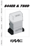
844 Slide Gate Operator FAAC International Inc. Headquarter & East Coast Operations 5151 Sunbeam Road Suites 9-11 Jacksonville, FL 32257 Tel. 866 925 3222 www.faacusa.com FAAC International Inc. West Coast Operations 357 South Acacia Avenue Unit 357 Fullerton, CA 92831 Tel. 800 221 8278 CONTENTS IMPORTANT SAFETY INFORMATION Important Safety Instructions Important Installation Instructions General Safety Precautions UL325 Gate Operator Classifications Installing the Warning Signs 1. DESCRIPTION & SPECIFICATIONS 1.1. 1.2 MAXIMUM USE CURVE TECHNICAL SPECIFICATIONS 4 4 4 5 6 6 7 7 8 2.DIMENSIONS 8 3. ELECTRIC EQUIPMENT (STANDARD) 8 4. INSTALLING THE SYSTEM 9 4.1. 4.2. 4.5. 5. PRELIMINARY CHECKS FOUNDATION PLATE INSTALLATION INSTALLATION OF CHAIN PINIONS CONTROL BOARD 780D 5.1.WARNINGS 5.2. 780D TECHNICAL SPECIFICATIONS 5.3. LAYOUT AND COMPONENTS 5.4. ELECTRIC CONNECTIONS 5.5.PROGRAMMING 6.START-UP 6.1. 6.2. 6.3. 6.4. 6.5. 6.6. 6.7. 6.8. ELECTRIC CONNECTIONS DEFINITION OF OPENING DIRECTION AND OPERATION OF LIMIT-SWITCH LEDS DETERMINING STOP POINTS AT TRAVEL LIMIT CHECK OF INPUTS CHECK OF MOTOR CONNECTION MECHANICAL CLUTCH ADJUSTMENT CHECK OF STOP POINTS SAFETY DEVICES AND ACCESSORIES CHECK 9 9 11 12 12 12 12 13 16 19 19 19 19 20 20 20 20 20 7. FINAL OPERATIONS 20 8. MANUAL OPERATION 21 9. RESTORING NORMAL OPERATION 21 10.MAINTENANCE 11.1. 11.2. DISASSEMBLING THE TRANSFORMER-BOARD UNIT OIL TOP-OFFS 21 21 21 12.REPAIRS 21 13. 24 844 SPARES DIAGRAM 14.TROUBLESHOOTING FAA C MODEL 84 4 Slide G at e O per at or 26 2 LIMITED WARRANTY 27 Read this instruction manual before you begin installing the product. = Information regarding personal safety and proper maintanence of the product. FAAC Model 844 - Rev: 01 - December 2010 3 FA A C M O D E L 8 4 4 S l i d e G a t e Ope r a t or IMPORTANT SAFETY INFORMATION Important Safety Instructions WARNING: TO REDUCE THE RISK OF SEVERE INJURY OR DEATH: • READ AND FOLLOW ALL INSTRUCTIONS. • Never let children operate or play with the gate controls. Keep remote controls away from children. • Always keep people and objects away from the gate. NO ONE SHOULD CROSS THE PATH OF A MOVING GATE. • Test the gate operator monthly. The gate MUST reverse on contact with a rigid object or when an object activates a non-contact sensor. If necessary, adjust the force or the limit of travel and then retest the gate operator. Failure to properly adjust and retest the gate operator can increase the risk of injury or death. • Use the manual release mechanism only when the gate is not moving. • KEEP GATE PROPERLY MAINTAINED. Have a qualified service person make repairs to gate hardware. • The entrance is for vehicles only. Pedestrians must use a separate entrance. • SAVE THESE INSTRUCTIONS. Important Installation Instructions 1. Install the gate operator only when the following conditions have been met: • The operator is appropriate for the type and usage class of the gate. • All openings of a horizontal slide gate have been guarded or screened from the bottom of the gate to a minimum of 4 feet (1.25 m) above the ground to prevent a 2.25 inch (55 mm) diameter sphere from passing through openings anywhere in the gate or through that portion of the adjacent fence that the gate covers when in the open position. • All exposed pinch points are eliminated or guarded. • Guarding is supplied for exposed rollers. 2. The operator is intended for installation on gates used by vehicles only. Pedestrians must be provided with a separate access opening. 3. To reduce the risk of entrapment when opening and closing, the gate must be installed in a location that allows adequate clearance between the gate and adjacent structures. Swinging gates shall not open outward into public access areas. 4. Before installing the gate operator, ensure that the gate has been properly installed and that it swings freely in both directions. Do not over-tighten the operator clutch or pressure relief valve to compensate for a damaged gate. 5. User controls must be installed at least 6 feet (1.83 m) away from any moving part of the gate and located where the user is prevented from reaching over, under, around or through the gate to operate the controls. Controls located outdoors or those that are easily accessible shall have security features to prevent unauthorized use. 6. The Stop and/or Reset buttons must be located within line-of-sight of the gate. Activation of the reset control shall not cause the operator to start. 7. All warning signs and placards must be installed and easily seen within visible proximity of the gate. A minimum of one warning sign shall be installed on each side of the gate. 8. For gate operators that utilize a non-contact sensor (photo beam or the like): FAA C MODEL 84 4 Slide G at e O per at or • See instructions on the placement of non-contact sensors for each type of application. • Exercise care to reduce the risk of nuisance tripping, such as when a vehicle trips the sensor while the gate is still moving. • Locate one or more non-contact sensors where the risk of entrapment or obstruction exists, such as at the reachable perimeter of a moving gate or barrier. • Use only FAAC “Photobeam” photoelectric eyes to comply with UL325. 4 General Safety Precautions Important Installation Instructions (continued) 9. For gate operators that utilize a contact sensor (edge sensor or similar): • Gate Construction Locate one or more contact sensors where the risk of entrapment or obstruction exists, such as at the leading edge, trailing edge, and post mounted both inside and outside of a vehicular horizontal slide gate Vehicular gates should be constructed and installed in accordance with ASTM F2200: Standard Specification for Automated Vehicular Gate Construction. • Locate one or more contact sensors at the bottom edge of a vehicular vertical lift gate. Installation • Locate one or more contact sensors at the bottom edge of a vertical barrier (arm). • For more information, contact ASTM at: www.astm.org • If you have any questions or concerns regarding the safety of the gate operating system, do not install the operator and consult the manufacturer. Locate one or more contact sensors at the pinch point of a vehicular vertical pivot gate. • The condition of the gate structure itself directly affects the reliability and safety of the gate operator. • Locate hard-wired contact sensors and wiring so that communication between sensor and gate operator is not subjected to mechanical damage. • • Locate wireless contact sensors, such as those that transmit radio frequency (RF) signals, where the transmission of signals are not obstructed or impeded by building structures, natural landscaping or similar hindrances. Wireless contact sensors shall function under their intended end-use conditions. Only qualified personnel should install this equipment. Failure to meet this requirement could cause severe injury and/or death, for which the manufacturer cannot be held responsible. • The installer must provide a main power switch that meets all applicable safety regulations. • It is extremely unsafe to compensate for a damaged gate by increasing hydraulic pressure. • Install devices such as reversing edges and photo beams to provide better protection for personal property and pedestrians. Install reversing devices that are appropriate to the gate design and application. • Before applying electrical power, ensure that voltage requirements of the equipment correspond to the supply voltage. Refer to the label on your gate operator system. • Use only FAAC MSE MO, CN60 or M60 edge sensors. Usage 5 • Use this equipment only in the capacity for which it was designed. Any use other than that stated should be considered improper and therefore dangerous. • The manufacturer cannot be held responsible for damage caused by improper, erroneous or unreasonable use. • If a gate system component malfunctions, disconnect the main power before attempting to repair it. • Do not impede the movement of the gate, you may injure yourself or damage the gate system as a result. • This equipment may reach high thermal temperatures during normal operation, therefore use caution when touching the external housing of the gate operator. • Use the manual release mechanism according to the procedures presented in this manual. • Before performing any cleaning or maintenance operations, disconnect power to the equipment. • All cleaning, maintenance or repair work must performed by qualified personnel. FA A C M O D E L 8 4 4 S l i d e G a t e Ope r a t or UL325 Gate Operator Classifications RESIDENTIAL VEHICULAR GATE OPERATOR CLASS I A vehicular gate operator system intended for use in a single family dwelling, garage or associated parking area. COMMERCIAL / GENERAL ACCESS VEHICULAR GATE OPERATOR CLASS II A vehicular gate operator system intended for use in commercial locations or buildings such as multi-family housing units (five or more single family units), hotels, parking garages, retail stores or other buildings that service the general public. INDUSTRIAL / LIMITED ACCESS VEHICULAR GATE OPERATOR CLASS III A vehicular gate operator system intended for use in industrial locations or buildings such as factories, loading docks or other locations not intended to service the general public. RESTRICTED ACCESS VEHICULAR GATE OPERATOR CLASS IV A vehicular gate operator system intended for use in guarded industrial locations or buildings such as airport security areas or other restricted access locations that do not service the general public, and in which unauthorized access is prevented via supervision by security personnel. Installing the Warning Signs This FAAC swing gate operator is supplied with two warning signs to alert people that a possible hazard exists and that appropriate actions should be taken to avoid the hazard or to reduce exposure to it. Permanently install one warning sign on each side of the gate so they are fully visible to traffic and pedestrians. Use appropriate hardware such as metal screws (not supplied) to permanently install each warning sign. FAA C MODEL 84 4 Slide G at e O per at or 6 MODEL 844 OPERATOR 1. DESCRIPTION & SPECIFICATIONS These instructions apply to the following models: 844 ER Z16 CR, 844 R, 844 R CAT, 844 R RF The FAAC Model 844 automated system for sliding gates is an electro-mechanical operator transmitting motion to the sliding leaf via a rack or chain pinion appropriately coupled to the gate. The non-reversing system ensures the gate is mechanically locked when the motor is not operating and, therefore, no lock needs to be installed. The gearmotor is equipped with a mechanical clutch which, combined with an electronic device, offers the necessary adjustable anti-crushing safety and guarantees stopping or reversing the gate movement. A handy manual release makes it possible to move the gate in the event of a power cut or malfunction. The control board, if supplied with the gearmotor, it is placed inside the operator. The 844 automated system was designed and manufactured to control access of vehicles. Avoid any other use whatever. Fig. 1 1.1. MAXIMUM USE CURVE The curve makes it possible to establish maximum work time (T) according to use frequency (F). The 844 gearmotor can operate non-stop at 70% use frequency. To ensure efficient operation, operate in the work range below the curve. Important: The curve is obtained at a temperature of 75°F. Exposure to direct sunlight can reduce use frequency down to 20%. Calculating Use Frequency The percentage of effective work time (opening + closing) compared to total time of cycle (opening + closing + pause times). Calculation Formula Ta + Tc Ta + Tc + Tp + Ti %F = X 100 Where: Ta = opening time Tc = closing time Tp = pause time Ti = time of interval (between 2 complete cycles) Us e Fre que nc y G ra ph % Freq. Used % Duty Cycle 100 90 80 70 60 50 1 Mounting Brackets 2Pinion 3 Limit Sensor Switch 4 Operator Cover 5 780 D Control Board 6 Adjustment Screw for Anti-crushing Clutch 7 Oil Filling Plug 8 Operator Grounding 9 Lever Operated Release System 10Protective Side Co 11Cover for 780D Control Board 40 30 20 10 0 1 2 3 4 5 6 7 8 9 10 11 12 Time (h) 7 FA A C M O D E L 8 4 4 S l i d e G a t e Ope r a t or 1.2 TECHNICAL SPECIFICATIONS TABLE 1: SPECIFICATIONS FOR 844 OPERATOR MODEL 844 Power Supply (VAC +6% -10% 60Hz) 115 or 230 Absorbed Power (W) 650 Reduction Ratio 1 : 30 Type of Pinion Z16 - Z20 Rack Module 4 - step 12.566 Max. Thrust (lbF) 250 (Z16) - 180 (Z20) Max. Torque (lbF/ft) 26 Winding Thermal Protection (°F) 248 Use Frequency 70% (see graph) Oil Quantity (Gallons) 0.5 Type of Oil FAAC XD 220 Ambient Operating Temperature (°F) -4 to +131 Weight (lbs) 32 Protection Class IP 44 Gate Max. Weight (lbs) 3950 (Z16) - 2200 (Z20) Gate Speed (feet/min) 32 (Z16) - 40 (Z20) Gate Max. Length (feet) 132 (Z16) - 164 (Z20) Clutch twin-disk in oil bath Protective Treatment cataphoresis Control Board 780D Limit-Switch magnetic or inductive Overall Dimensions LxHxD (inches) See Fig. 2 2.DIMENSIONS Fig. 2 6 8¾ 15 ¼ 7½ 10 ¾ - Measurements in Inches 3. ELECTRIC EQUIPMENT (STANDARD) Fig. 3 VAC ~ 15 AWG Electric Motor Technical Specifications RPM 1700 Power (W) 650 Absorbed Current (A) 3.5 (230V) ; 7 (115V) Starting Capacitor (µF) 35 (230V) ; 70 (115V) Power Supply (VAC +6% -10%; 60Hz) 115 or 230 20 G AW 20 G AW WG G A G AW 20 15 0 AW 2 Operator 844 with 780D equipment Photocells Key-operated push-button Flashing lamp Radio receiver FAA C MODEL 84 4 Slide G at e O per at or 8 4. 4.1. INSTALLING THE SYSTEM PRELIMINARY CHECKS To ensure safety and an efficiently operating automated system, make sure the following conditions are observed: 2 • The gate structure must be suitable for automation. For example, wheel diameter must be in proportion to the weight of the gate to be automated, an upper guide must be provided, mechanical stop limits to prevent the gate derailing must be installed. • The soil must permit sufficient stability for the concrete pad. 8¾ - Measurements in Inches • There must be no pipes or electric cables in the pad excavation area. Fig. 5 • If the operator is exposed to passing vehicles, install, if possible, adequate means of protection against accidental impact. Fig. 6 0 to 2 • Check if an efficient grounding is available for connection to the gearmotor. FOUNDATION PLATE INSTALLATION 2 4.2. 1. Assemble the foundation plate as shown in Fig 4. The foundation plate must be located as shown in Fig 5 (right closing) or Fig 6 (left closing) to ensure that the rack and pinion mesh correctly. 2. Prepare a concrete pad as shown in Fig.7, following the suggested dimensions. It’s recommended to have the pad a minimum of 4” above level grade to avoid any flooding of the operator. The underground depth of the concrete pad is determined by the soil condition and the local building codes. Make sure the concrete pad is leveled. - Measurements in Inches Fig. 7 3 .5 11 1. 75 3 2⅜ 25 2⅜ 1. 75 4 4. After the concrete is poured in the forms and before it has a chance to set, insert the foundation plate into the cement and position it flush with the top of the concrete and aligned with the top of the lower gate frame. Use the dimensions shown in Figs 5 or 6 to align your foundation plate. Allow the concrete to set for a minimum of two days before installing the operator. 6. 0.25 3. Provide one or more conduit pathways for all power and accessory connections. Extend the conduit about of 1/2” above the level of the concrete pad. 7 5. Route the wires in the conduits. To facilitate the connections allow for about 15” of extra length of cables out of the conduit. Separate the high and low voltage wires in different conduits. .25 12 - Measurements in Inches 4.3. Fig. 4 6 0 to 2 MECHANICAL INSTALLATION 1. Assemble the mounting brackets and anti-vibration spacers on the operator as shown in Fig. 8. 2. Open the cover, remove the securing screws. 3. Attach the operator to the plate, using the supplied washers and nuts as shown in Fig. 9. 2.5 4. During this operation, route cables through the opening inside the lower half-casing of the operator (Fig.10 - Ref. A). 9 To access the electronic equipment, route the cables through the appropriate hole, using the supplied rubber cable-clamp. Make sure to strip the jacket on all cables so that the clamp holds single cables only (Fig.10 - Ref. B). - Measurements in Inches FA A C M O D E L 8 4 4 S l i d e G a t e Ope r a t or 5. Secure the operator to the foundation plate, tighten nuts as shown in Fig. 12. 6. Prepare the operator for manual operating mode as described in Section 8. Fig. 12 Fig. 8 4.4. INSTALLING THE RACK 4.4.1. STEEL RACK TO WELD (Fig. 13) 1. Place the three threaded dowel nuts on the rack element, positioning them at the top of the slot. In this way, the slot play will allow any adjustments to be made. 2. Manually move the leaf to its closed position. 3. Lay the first piece of rack level on the pinion and weld the threaded dowel nut to the gate as shown in Fig. 15. 4. Move the gate manually, checking that the rack is resting on the pinion, then weld the second and third dowel nut. 5. Place another rack element next to the previous one, use a third piece of rack (as shown in Fig. 16) to synchronize the teeth of the first two elements. 6. Move the gate manually and weld the three threaded dowel nuts. Proceed as described until the gate is fully covered. 15 ¾ Fig. 9 4.4.2. Manually move the leaf to its closing position. 2. Lay the first piece of rack level on the pinion and place the spacer between the rack and the gate, positioning it at the top of the slot. 3. Mark the drilling point on the gate. Drill a Ø ¼ inch hole and apply thread with a Ø 5/16 inch male tap. Screw in the bolt. 4. Move the gate manually, checking that the rack is resting on the pinion. Repeat step 3. 5. Place another rack element next to the previous one, use a third piece of rack (as shown in Fig. 16) to synchronize the teeth of the first two elements. 6. Move the gate manually and secure the first element. Proceed as previously described until the gate is fully covered. ⅝ to 1 ¼ 2½ 4 ⅜ (Z16) 4 ¾ (Z20) Fig. 10B 2 - Measurements in Inches Fig. 11 FAA C MODEL 84 4 Slide G at e O per at or STEEL RACK TO SCREW (Fig. 14) 1. - Measurements in Inches Fig. 10A Fig. 13 Fig. 14 Fig. 15 10 4.5.2. MODEL 844 ER RF (Figs. 20 & 21) 1. Insert the pin g on the shaft, using a hammer. 2. Fit the idle transmissions bracket on the operator flange, using the four screws a (M5 x 12) and the appropriate washers b, in the kit as shown in Fig. 20. 3. Fit the chain pinion on the shaft, making the channel coincide with the pin and tighten the screw d and the appropriate washers e and f. Fig. 16 Notes on Rack Installation • Make sure that, during gate travel, no rack elements derail from the pinion. • Do not, for any reason, weld the rack elements either to the spacers or to each other. 4. Pass the chain as shown in Fig. 21A and install the cover with screw a and washer c as in Fig. 20. 4.5.3. LIMIT SWITCHES In case of operators with magnetic limit switches, you have to provide a bracket to mount them on the gate, following the proper distances showed in Fig. 21B. Fig. 20 g • When the rack has been installed, to ensure that it meshes correctly with the pinion, lower the gearmotor position by about 1/16 inch (Fig. 17). 16 inch a c 1 • Manually check that the gate regularly reaches the mechanical stop limits and make sure there is no friction during gate travel. b a f e Fig. 17 d • Do not use grease or other lubricants between rack and pinion. 4.5. INSTALLATION OF CHAIN PINIONS Fig. 21A The operators for chain and idle transmissions require the installation of a Z16 or Z20 chain pinion. 4.5.1. MODEL 844 ER CAT (Figs. 18 & 19) 1. Insert the pin on the shaft, using a hammer. 2. Fit the chain pinion on the shaft, making the channel coincide with the pin. Tighten the screw and the appropriate washers. Fig. 18 ⅛ to ½ 0 to ⅜ Fig. 21B Fig. 19 - Measurements in Inches 11 FA A C M O D E L 8 4 4 S l i d e G a t e Ope r a t or 5. 780D Technical Specifications (continued) CONTROL BOARD 780D 5.1.WARNINGS Important: Before attempting any work on the control board (connections, maintenance), always turn off power. • Check local wiring codes in all cases and follow all local building codes. Wiring and hookup should be performed by qualified electricians/installers only. • AC power should be supplied from a circuit breaker panel and must have its own dedicated circuit breaker. This supply must include a green ground conductor. Absorbed Power (W) 10 Motor Max. Load (W) 1000 Accessories Max. Load (A) 0.5 Operating Ambient Temperature -4°F to +131°F Protection Fuses 2 (see Fig. 22 and Section 5.3) Function Logics Automatic / “Stepped” automatic / Semi-automatic / Safety devices / Semi-automatic B / Dead-man C / “Stepped” semi-automatic / Mixed B/C logic 5-pin card connection for RP receivers Programming 3 keys (+, -, F) and display, "basic" or "advanced" mode LAYOUT AND COMPONENTS SIGNALLING AND PROGRAMMING DISPLAY Led INPUTS STATUS CONTROL LED 780D TECHNICAL SPECIFICATIONS 115 or 230 Rapid Connector DL • Always separate power cables from control and safety cables (push-button, receiver, photocells, etc.). Power Supply V~ (+6% -10%) Flashing lamp - Motor - 24 VDC accessories power supply- 24 VDC indicator-light / Timed output / Electric lock command - 'traffic lights' - Failsafe 5.3. • Properly ground the gate operator to minimize or prevent damage from power surges and/or lightning. Use a grounding rod if necessary. Connect the ground cable to the PE terminal on J7 (Fig. 22), and to the ground lug on the operator (Fig. 40). A surge suppressor is recommended for additional protection. 5.2. Terminal Board Outputs J1 LOW VOLTAGE TERMINAL BLOCK J2 CONNECTOR FOR RP RECEIVER J5 CONNECTOR FOR MOTOR STARTING CAPACITOR J6 MOTOR AND FLASHING LAMP CONNECTION TERMINAL BLOCK J7 VAC POWER SUPPLY TERMINAL BLOCK J8 DOUBLE CONNECTOR - RAPID CONNECTION TO LIMIT-SWITCH F1 MOTOR AND TRANSFORMER PRIMARY WINDING FUSE (F 5A - 230V; F 10A - 115V) F2 LOW VOLTAGE AND ACCESSORIES FUSE (T 800mA) F "F" PROGRAMMING PUSH-BUTTON – "–" PROGRAMMING PUSH-BUTTON + "+" PROGRAMMING PUSH-BUTTON J1 CONNECTOR Work Time Programmable (from 0 to 4.1 min.) Pause Time Programmable (from 0 to 4.1 min.) Thrust Force Adjustable over 50 levels Terminal Board Inputs Open - Partial Open - Opening safety devices - Closing safety devices - Stop - Edge - Power supply+ground On-Connector Inputs Opening and closing limit-switch Motor capacitor 1 OPEN A (total opening) 2 OPEN B (partial opening) 3 FSW-OP (opening safety devices) 4 FSW-CL (closing safety devices) 5STOP 6 SAFE (“edge” safety devices) 7 - (negative for power supply to accessories) 8 - (negative for power supply to accessories) 9 +24V (supply to accessories) 10 +24V (supply to accessories) 11 FSW-TX (negative for emitting photocells - FAILSAFE) 12 AA (negative for Audio Alarm) + J7 J8 – F J1 J5 J6 DL F1 Led J2 Led F2 Fig. 22 FAA C MODEL 84 4 Slide G at e O per at or 12 5.4. ELECTRIC CONNECTIONS ~ VAC BLUE VAC (Max. 60W) Capacitor J5 LIMIT-SWITCH J1 Closing Safety Devices: Tripped when an obstacle is detected only during gate closing movement. They cause reversing, either immediate or on release (see programming in Section 5.5.2.) Opening/Closing Safety Devices: Tripped during the gate opening and closing movements. They cause stopping and restart motion on release. "Edge" Safety Devices: Tripped during the gate opening and closing movements. They cause immediate reversal of motion and stopping after two seconds. Encoder: Monitors for an obstacle during gate opening and closing movements. It causes immediate reversal of motion and stopping after two seconds. N.B: If two or more safety devices have the same function (opening, closing, opening and closing, edge), the contacts must be connected to each other in series (Fig. 25). AA SAFE CL OP OPEN A OPEN B + + Opening Safety Devices: Tripped when an obstacle is detected only during gate opening movement. They cause immediate reversing and resumption of the opening motion on release (see programming in Section 5.5.2.) N.C. contacts must be used. N.B: If safety devices are not used, jumper the terminals as shown in Fig. 26. Audio Alarm 24 Vcc max. 125mA For connection of the photocells and safety devices, see Section 5.4.1. PARTIAL OPEN TOTAL OPEN The most common photocell and safety device lay-outs are shown below (from Fig. 27 to Fig. 34). Connection of two N.C. contacts in series (e.g. Photocells, Stop, Edge, etc.) Fig. 25 STOP + + OP CL SAFE A OPEN B OPEN A Connection of no safety device Fig. 23 Fig. 26 Closing photocells + + SAFE CL OP Connection of a closing safety device and an opening safety device OPEN B Before connecting safety devices and photocells, it is advisable to select the type of operation according to the area they have to protect (see Fig. 24 for example). OPEN A 5.4.1. Connection of Photocells and Safety Devices Opening or opening/ closing photocells Fig. 27 + + SAFE CL OP "Edge" safety devices Closing photocells OPEN B OPEN A Connection of an "edge" safety device Fig. 24 Fig. 28 13 FA A C M O D E L 8 4 4 S l i d e G a t e Ope r a t or + + SAFE OP CL OPEN A + + SAFE OP CL OPEN B OPEN A OPEN B Connection of two pairs of closing photocells and two edge safety devices Connection of a pair of opening photocells Fig. 29 + + SAFE OP CL OPEN B OPEN A Connection of a pair of closing photocells Fig. 32 + + SAFE CL OP OPEN B OPEN A Connection of a pair of closing photocells, a pair of opening photocells and a pair of opening/closing photocells Fig. 30 + + SAFE CL OP OPEN B OPEN A Connection of a pair of opening photocells, a pair of closing photocell and an edge safety device TX OP/CL TX OP RX OP RX OP Fig. 31 FAA C MODEL 84 4 Slide G at e O per at or RX OP/CL TX OP Fig. 33 14 + + SAFE OP CL OPEN B OPEN A Connection of a pair of closing photocells and a pair of opening/closing photocells FSW OP - Opening Safety Devices Contact (Terminal 3): The purpose of the opening safety devices is to protect the leaf movement area during opening. During opening, in the A-AP-S-E-EP logics the safety devices reverse the movement of the gate, or stop and restart the movement when it is released (see advanced programming in Section 5.5.2). During the opening cycle in logicsthe B, C and B/C, they interrupt movement. They never operate during the closing cycle. If the Opening safety devices are engaged when the gate is closed, they prevent the opening movement. To install several safety devices, connect the N.C. contacts in series (Fig.25). TX OP/CL RX OP/CL Fig. 34 Connection of two N.O. contacts in parallel (e.g. Open A, Open B) Fig. 35 5.4.2. J7 Terminal Block - Power Supply (Fig. 23) POWER SUPPLY (Terminals PE-N-L): PE: Ground connection N: AC Power ( Neutral ) L : AC Power ( Line ) 5.4.3. J6 Terminal Block - Motors / Flashing Lamp (Fig. 23) MOTOR - (Terminals MOT-C, MOT-1, MOT-2): Motor connection (see Section 6.5). LAMP - (Terminals LAMP L, LAMP N): Flashing lamp output same VAC as input; max 60W. 5.4.4. J1 Terminal Block - Accessories (Fig. 23) Consult the relevant tables for a detailed description of operation in the different logics OPEN A - “Total Opening” Command (Terminal 1): any pulse generator (push-button, detector, etc.) which, by closing a contact, commands total opening and/or closing of the gate leaf. To install several total opening pulse generators, connect the N.O. contacts in parallel (Fig. 35). OPEN B - “Partial Opening” or “Closing” Command (Terminal 2): any pulse generator (push-button, detector, etc.) which, by closing a contact, commands partial opening and/or closing of the gate leaf. In the B, C and B/C logics, it always commands gate closure. NB: If no opening safety devices are connected, jumper inputs FSW OP and -TX FSW (Fig. 26). FSW CL - Closing Safety Devices Contact (Terminal 4): The purpose of the closing safety devices is to protect the gate movement area during closing. During closing, in the A-AP-S-E-EP logics, the safety devices reverse the movement of the gate, or stop and reverse the movement when it is released (see advanced programming in Section 5.5.2). During the closing cycle in logics B, C and B/C, they interrupt movement. They never operate during the opening cycle. If the Closing safety devices are engaged when the gate is open, they prevent the closing movement. To install several safety devices, connect the N.C. contacts in series (Fig.25). NB: If no closing safety devices are connected, jumper terminals FSW CL and -TX FSW (Fig. 26). STOP - STOP Contact (Terminal 5): Any device (e.g. a push-button) which, by opening a contact, stops gate movement. To install several STOP devices, connect the N.C. contacts in series (Fig. 25). NB: If STOP devices are not connected, jumper the STOP and - terminals. SAFE - EDGE Safety Device Contact (Terminal 6): The purpose of the "edge" safety device is to protect the leaf movement area during opening/closing. In all logics, during opening and closing, the safety device reverses gate movement for 2 seconds. If the safety devices operate again during the 2-seconds reversing time, it stops movement (STOP) without any reversing. If the Edge safety device is engaged while the gate is closed or open, it prevents movement. To install several safety devices, connect the N.C. contacts in series (Fig.25). NB: If edge safety devices are not connected, jumper the SAFE and - inputs (Fig. 26). – Negative for power supply to accessories (Terminals 7 and 8) + 24 VDC - Positive for power supply to accessories (Terminals 9 and 10) Important: Accessories max. load is 500 mA. To calculate the load, refer to the instructions for the individual accessories. To install several partial opening pulse generators, connect the N.O. contacts in parallel (Fig. 35). 15 FA A C M O D E L 8 4 4 S l i d e G a t e Ope r a t or TX -FSW - Negative for Power Supply to Photocell Transmitters (Terminal 11) If you use this terminal to connect the negative transmitters of the photocell power, you may, if necessary, also use the FAIL SAFE function (see advanced programming in Section 5.5.2). If this function is enabled, the equipment checks operation of the photocells before every opening or closing cycle. 5.5.PROGRAMMING To program operation of the automated system, access the "PROGRAMMING" mode with keys F,+ and - on the cover. Attention: before attempting to power up the system, re-position the board's cover to avoid contact with high voltage parts and to access the push-button keys on the cover (Fig. 39). + A.A. - Power Supply to Audio Alarm (Terminal 12) - F Connect a 24 VDC - 125mA max audio alarm compliant with UL325. 31.1.4. The alarm will sound upon two sequential activations of an entrapment protection device, continuosly until the activation of a STOP command. To comply with UL325 the STOP input must be connected to a wired control located in the line-of-sight of the gate. 5.4.5. J2 Connector - Rapid Connection to RP This is used for rapid connection of RP receivers (see Fig. 38). Fit the accessory with the components side toward connector J1. Insert and remove after cutting power. 5.4.6. Quick-fit connector for connecting the motor starting capacitor. 5.4.7. Fig. 39 J5 Connector - Rapid Connection to Capacitor Double Connector J8 - Limit-Switch Quick Fit Quick-fit connector for connecting the limit-switch. For connecting both the MLS magnetic limit-switch and the inductive limit-switch (Fig. 23 Ref. ) to the operator. Programming is divided in two parts: BASIC and ADVANCED. 5.5.1. BASIC PROGRAMMING To access BASIC PROGRAMMING, press key F: • If you press it (and hold it down), the display shows the name of the first function. • If you release the key, the display shows the value of the function that can be modified with keys + and -. • If you press F again (and hold it down), the display shows the name of the next function, etc. • When you reach the last function, press F to exit the program, and the display resumes showing the gate status. The following table shows the sequence of functions accessible in BASIC PROGRAMMING: BASIC PROGRAMMING RP Display F Function FUNCTION LOGICS (see table of logics): Default = Automatic = "Stepped" automatic = "Safety" Automatic = Semi-automatic = "Stepped" Semi-automatic = Dead-man Fig. 38 = "B" Semi-automatic = Mixed Log. (B opening / C closing) PAUSE TIME: This has effect only if automatic logic was selected. Adjustable from to sec. in onesecond steps. Subsequently, display changes to minutes and tens of seconds (separated by a point) and time is adjusted in 10-second steps, up to the maximum value of minutes. E.g. if the display shows , pause time is 2 min. and 50 sec. FAA C MODEL 84 4 Slide G at e O per at or 16 Display Function FORCE: Default Adjusts Motor thrust. FAIL SAFE: Function Default If this function is activated, it enables a function test of the photocells before any gate movement. If the test fails (photocells not working are indicated by the value on the display), the gate does not start moving. = minimum force = maximum force OPENING DIRECTION: Indicates the gate opening movement and makes it possible not to change the motor connections on the terminal board. = Active = Disabled PRE-FLASHING (5 s): = Rightward opening movement = Leftward opening movement Activates the flashing lamp for 5 seconds before start of movement. STATUS OF AUTOMATED SYSTEM: Exit from programming, save data, and return to gate status viewing. = Disabled = Only before opening = Only before closing = Before every movement = Closed = Now opening = At "STOP" = Open = Pause = "FAIL SAFE" tripped = Now closing = Now reversing = Photocells tripped 5.5.2. Display RESERVED: Fixed to ADVANCED PROGRAMMING To access ADVANCED PROGRAMMING, press key F and, as you hold it down, press key +: • If you release key + , the display indicates the name of the first function. • If you release key F too, the display shows the value of the function that can be modified with keys + and -. • If you press key F (and hold it down), the display shows the name of the next function, and if you release it, the value that can be modified with keys + and - is shown. • When you reach the last function, press F to exit the program, and the display resumes showing the gate status. The following table shows the sequence of functions accessible in ADVANCED PROGRAMMING: ADVANCED PROGRAMMING F Display + Function MAXIMUM TORQUE AT INITIAL THRUST: + Default The motor operate at maximum torque (ignoring the torque setting) at start of movement. Useful for heavy leaves. = Active = Disabled FINAL BRAKING: When the gate reaches the opening or closing limit-switch, a braking stroke can be selected to ensure the leaf is stopped immediately. If decelerations are selected, braking starts when they finish. At value, braking is disabled. Time can be adjusted from 0.01-second steps. to = Braking disabled from 17 to = Timed braking in CLOSING PHOTOCELLS LOGIC: Select the tripping mode of the closing photocells. They operate for the closing movement only: they stop movement and reverse it when they are released, or they reverse it immediately. = Reverse on release = Reverse immediately to opening FA A C M O D E L 8 4 4 S l i d e G a t e Ope r a t or Display Function OPENING PHOTOCELLS LOGIC: Default Select the tripping mode of the opening photocells. They operate for the opening movement only: they stop the movement and restart it when they are released, or they reverse it immediately. = Reverse immediately to closing = Restart movement on release ENCODER: If the encoder is present, you may enable its use. If the encoder is present and enabled, "decelerations" and "partial opening" are controlled by it (see relevant paragraphs). The encoder operates as an anti-crushing device. If the gate hits an obstacle during opening or closing, the encoder immediately reverses the gate leaf movement for 2 seconds. If the encoder operates again during the 2-seconds reversing time, the movement stops (STOP) without commanding any reversing. If no encoder is supplied, the parameter must be set to . If there is the encoder, adjust the sensitivity of the anti-crushing system, by varying the parameter between (maximum sensitivity) and (minimum sensitivity). From to sitivity adjustment = Encoder active and sen- = Encoder disabled Pre-limit switch DECELERATION: You can select gate deceleration before the opening and closing limit-switches have been tripped. Time can be adjusted from 0.1-second steps. to in If an encoder is used, the adjustment is not determined by time but by motor revs, thus obtaining greater deceleration precision. = Deceleration disabled From to = Deceleration enabled Post-limit switch DECELERATION: You can select gate deceleration after the opening and closing limit-switches have been tripped. Time can be adjusted from 0.1-second steps. to in If an encoder is used, the adjustment is not determined by time but by motor revs, thus obtaining greater deceleration precision. = Deceleration disabled from to = Deceleration enabled FAA C MODEL 84 4 Slide G at e O per at or Display Function PARTIAL OPENING: Default You can adjust the width of partial leaf opening. Time can be adjusted from 1-second steps. to in If an encoder is used, the adjustment is not determined by time but by motor revs, thus obtaining greater partial-opening precision. For example, with pinion Z20, partial opening can vary from 2' to 13'. WORK TIME (time-out): It is advisable to set a value of 5 to 10 seconds over the time taken by the gate to travel from the closing limit-switch to the opening limitswitch and vice versa. Adjustable from steps. to sec. in one-second Subsequently, display changes to minutes and tens of seconds (separated by a point) and time is adjusted in 10 second steps, up to a maximum value of minutes. Attention: the set value will not exactly match the motor's maximum operating time if decelerations are used. ASSISTANCE REQUEST with next function): (combined If activated, at the end of countdown (see the next function: "Cycle Programming") it effects 2 sec. (in addition to the value already set with the PF function) of pre-flashing at every Open pulse (job request). It can be useful to set scheduled maintenance jobs. = Active = Disabled CYCLE PROGRAMMING: To set countdown of system operation cycles. Settable (in thousands) from to thousand cycles. The displayed value is updated as cycles proceed. GATE STATUS: Exit from programming, save data and return to viewing gate status (see Section 5.5.1.). Note 1: To reset the programming default settings, check that the edge input is closed (SAFE LED ON), and simultaneously press keys +, - and F, holding them down for 5 seconds. Note 2: Modifications of programming parameters take effect immediately, whereas changes are saved to memory only after you exit programming and return to normal gate status viewing. If the equipment is powered down before returning to status viewing, any modifications will be lost. 18 6.START-UP 6.1. ELECTRIC CONNECTIONS Make all electrical connections to the board as described in Section 5, including grounding the operator (Fig. 39). Attention: Due to the powerful magnetic fields produced by the supplied magnets, do not place magnetic storage devices (credit cards, magnetic tapes, floppy disks, etc) or sensitive electronic equipment (watches, CRT monitors, LCD screens, etc.) near the magnets. Notes on Magnet Positioning Fig. 40 6.2. DEFINITION OF OPENING DIRECTION AND OPERATION OF LIMIT-SWITCH LEDS • To ensure correct operation, allow at least 3/4 inch from the mechanical stop limit in the gate stop position. Carry out this check after determining the values of the pre- and post-limit switch decelerations (see Section 5.5.2.) and after running at least one complete cycle of the automated system. • The distance between the limit-switch and magnets must be from 1/4 to 1/2 inch. • Magnets should be fitted on the rack and not on the screws. If necessary, position the magnet at the side of the screw and adjust decelerations (see Section 5.5.2) in order to obtain the correct stop point. Power up the system and set the opening direction on the board (see Section 5.5.1). If opening direction is to the RIGHT ( FC1 ): OPENING limit-switch LED = FC1 CLOSING limit-switch LED = FC2 If opening direction is to the LEFT ( ): OPENING limit-switch LED = FC2 FC2 CLOSING limit-switch LED = FC1 6.3. DETERMINING STOP POINTS AT TRAVEL LIMIT Operator 844 has a limit sensor switch which, by detecting the transit of a reference applied to the rack, commands the motor to stop. The device can be magnetic (Fig. 41) or inductive (Fig. 42). 6.3.1. Magnetic Limit-Switch (MLS) The MLS limit-switch detects the transit of two magnets fitted on the side of the rack facing the operator. Procedure for correct positioning of the two supplied magnets: 6.3.2. Inductive Limit-Switch Operator 844 has an inductive limit-switch which detects the travel of the two steel plates fitted on the top of the rack. Procedure for correct positioning of the two supplied steel plates: Manually open the gate to within 3/4 to 2 inches of the travel limit mechanical stop. Assemble the limit-switch by centering the plate with respect to the threaded pins of the support (Fig. 42). 2. Fit the magnet (without removing the protective film from the adhesive side) on the side of the rack facing the operator, aligning the upper edges. Slide the magnet on the rack in opening direction until the relevant LED goes off (Fig. 22 and 41), then move the magnet forward an additional 1 3/4 inches. Check that the operator is in manual operating mode (see Section 8). 3. Manually open the gate to within 3/4 to 2 inches of the mechanical stop limit. 4. Allow the plate to move on the rack in opening direction until the relevant LED goes off (Figs. 22 and 42); next, move the plate forward an additional 1 3/4 inches and secure it to the rack by tightening the screws. 5. Manually close the gate to within 3/4 to 2 inches of the mechanical stop limit. 6. Allow the plate to move on the rack in closing direction until the relevant LED goes off (Figs. 22 and 42); next, move the plate forward by an additional 1 3/4 inches and secure it to the rack by tightening the screws. Check that the operator is in manual mode (see Section 8). 2. 3. 4. Manually close the gate to within 3/4 to 2 inches of the travel limit mechanical stop. 5. Fit the magnet (without removing the protective film from the adhesive side) on the side of the rack facing the operator, aligning the upper edges. Slide the magnet on the rack in closing direction until the relevant LED goes off (Fig. 22 and 41), then move the magnet forward an additional 1 3/4 inches. 6. Move the gate to its halfway travel point and relock the system (see Section 9). 7. Find out the desired pre- and post-limit-switch deceleration values (see Section 5.5.2) and run the automated system for at least one complete cycle. 8. Check that the gate stops approximately 3/4 to 2 inches from its mechanical stop point. If necessary, correct the position of the magnets and check that the stop point is correct. FC1 FC2 Mark the position of the magnets on the rack, and remove them. 10. Clean the rack on its fitting points, remove the film on the adhesive parts of the magnets (Fig. 41 Ref. 1) and re-position the magnets with the adhesive strip in contact with the rack (Fig. 41 Ref. 2). 19 Fig. 41 1. 1. 9. 1 2 Fig. 42 FA A C M O D E L 8 4 4 S l i d e G a t e Ope r a t or Notes on Plate Positioning • To ensure correct operation, allow at least 3/4 inch from the mechanical stop limit in the gate stop position. Carry out this check after determining the values of the pre- and post-limit switch decelerations (see Section 5.5.2.) and after running at least one complete cycle of the automated system. • A B The distance between the limit-switch and the plates must be < 3/16 inch. 6.4. Fig. 44 CHECK OF INPUTS The table below shows the status of the LEDs in relation to to the status of the inputs. Note the following: Led ON = closed contact Led OFF = open contact Check the status of the LEDs as per the following table. Table 2: Operation of the Signalling Status LEDs LEDS ON OFF OP-A Command activated OP-B Command activated Command inactive Command inactive FC1 Limit-switch free Limit-switch engaged FC2 Limit-switch free Limit-switch engaged FSW OP Safety devices disengaged Safety devices engaged FSW CL Safety devices disengaged Safety devices engaged STOP Command inactive SAFE Safety devices disengaged Safety devices engaged ENC Flashes while the motor rotates Command activated 6.7. Be careful when setting the post-limit-switch deceleration and braking. If the deceleration is too long and braking is insufficient, the magnet or steel plate fitted on the gate's rack can overshoot the sensor until it is disengaged. When the gate stops, check that only the light limit-switch is engaged. The relevant LED must be OFF. If it went OFF and then ON again, or if both limit-switch LEDS are OFF, you must reduce the post-limit-switch deceleration value and/or increase the braking value (see Section 5.5.2). 6.8. SAFETY DEVICES AND ACCESSORIES CHECK Check for the correct operation of all safety equipment, anticrushing devices (ENCODER sensor), and accessories used in the system. NB: The status of the LEDs while the gate is closed are shown in bold. If opening direction is to the left, the status of LEDS FC1 and FC2 is reversed. 7. 6.5. • CHECK OF MOTOR CONNECTION Check that the motor wiring is as shown in Fig. 43 (standard connection). 6.6. MOT 2 MOT 1 MOT COM CHECK OF STOP POINTS FINAL OPERATIONS After installation, apply the danger sticker to the top of the cover (Fig. 45). Fig. 45 BROWN BLACK BLUE J6 M Fig. 43 MECHANICAL CLUTCH ADJUSTMENT In addition to its electronic safety devices (encoder and force adjustment), the 844 operator is also equipped with a mechanical clutch. For gate force and the encoder, please consult Sections 5.5.1 and 5.5.2. Adjusting the Operating Threshold of the Mechanical Clutch: 1. Cut electrical power to the automated system. • Snap-fit the side panels, put the equipment's cover on and secure it with the supplied screws (Fig. 46). • Remove the vent stop screw (Fig. 47). • Explain to the customer the correct operation and use of the operator, and indicate the potentially dangerous areas of the automated system. Fig. 46 2. Keep the motor shaft locked with a wrench and turn the clutch adjustment screw with an Allen wrench or screwdriver as shown in Fig. 44 Ref. A. - To increase torque, turn the screw clockwise. - To reduce torque, turn the screw counter-clockwise. The operator is supplied with the clutch set to maximum level. Therefore, you must initially turn the screw counter-clockwise to reach the best setting. 3. Power up the automated system and check that the torque you have just set is correct. The operator is supplied as standard with a clutch adjustment spring for gates up to 2200 lbs. For heavier gates, use the supplied alternative spring. For spring replacement instructions, see Fig. 44 Ref. B. FAA C MODEL 84 4 Slide G at e O per at or 20 10.MAINTENANCE Check the operational efficiency of the system at least once every 6 months, especially the efficiency of the safety and release devices (including operator thrust force). 11.1. DISASSEMBLING THE TRANSFORMERBOARD UNIT If you have to disassemble the transformer-board unit, proceed as follows: Fig. 47 8. Remove all terminal boards and connectors from the board. Unscrew the 3 screws from the board and the 2 from the transformer. Lift the unit up and gently remove the transformer from the couplings on the board as shown in Fig. 53. MANUAL OPERATION If the gate has to be operated manually due to a power blackout or malfunction of the automated system, use the release device as follows: 1. Open the protection door and insert the supplied key in the lock (Fig. 48). Fig. 53 Fig. 48 11.2. OIL TOP-OFFS Periodically check the oil level inside the operator. 2. Turn the key clockwise and pull the release lever as shown in Fig. 49. A once-a-year check is enough for medium or low usage. For heavy duty usage, a check every 6 months is recommended. 3. Open and close the gate manually. To access the tank, temporarily remove the plastic oil filler cap (Fig. 54). Oil level is visually checked and must cover the copper coil of the electric motor. If more oil is needed, add it through the oil filler hole. Use FAAC XD 220 oil only. Fig. 49 9. RESTORING NORMAL OPERATION To prevent an involuntary pulse from activating the gate, cut power to the system before re-locking the operator. 1. Re-close the release lever. 2. Turn the key counter-clockwise 3. Remove the key and close the lock protection door. Fig. 54 4. Move the gate until the release engages. 12.REPAIRS For any repairs, contact an FAAC authorized repair center. 21 FA A C M O D E L 8 4 4 S l i d e G a t e Ope r a t or 22 FA A C M O D E L 8 4 4 S l i d e G a t e Ope r a t or No effect (1) (3) Closes the leaf (3) O PEN I N G LO C K E D Stops operation (3) Closes the leaf (with Closing Safety devices engaged, opens at the 2nd pulse) (3) O PEN I N G LO C K E D Re-opens the leaf immediately Stops operation (3) Closes the leaf (with Closing Safety devices engaged, opens at the 2nd pulse) (3) C LO S I N G O PEN I N G LO C K E D Opens leaf for the partial opening time Re-closes the leaf immediately (3) Opens the leaf C LO S E D O PEN O PEN - A Lo g ic "E " G A TE S TA TUS O PEN - B Closes the leaf (3) LO C K E D Tab. 3/d Re-closes the leaf immediately (3) O PEN I N G Re-opens the leaf immediately C LO S I N G C LO S E D Re-closes the leaf immediately (3) Opens leaf for the partial opening time and closes after pause time Opens the leaf and closes it after pause time O P E N o n PA US E O PEN - B O PEN - A G A TE S TA TUS Lo g ic "S " Tab. 3/c Re-opens the leaf immediately C LO S I N G Opens the leaf and closes it after pause time C LO S E D Stops operation (3) Opens leaf for the partial opening time and closes after pause time O P E N o n PA US E O PEN - B O PEN - A G A TE S TA TUS Lo g ic "A P " Tab. 3/b Re-opens the leaf immediately (1) C LO S I N G C LO S E D Reloads pause time (1)(3) Opens leaf for the partial opening time and closes after pause time (1) Opens the leaf and closes it after pause time (1) O P E N o n PA US E O PEN - B O PEN - A G A TE S TA TUS Lo g ic "A " Tab. 3/a No effect (OPEN disabled) Stops operation S TO P No effect (OPEN disabled) Stops operation S TO P No effect (OPEN disabled) Stops operation S TO P No effect (OPEN disabled) Stops operation S TO P P ULS E S No effect C LO S I N G S A FE TY D E V I C E S see paragraph 5.5.2. No effect (saves OPEN) No effect No effect (if on part.opng. OPEN A disabled) No effect (OPEN disabled) O P E N I N G S A FE TY D E V I C E S Reverses to close for 2" (2) Reverses to close for 2" (2) Locks and, on release, continues opening No effect see paragraph 5.5.2. Reverses to close for 2" (2) Reverses to open for 2" (2) Reloads pause time (1) (OPEN disabled) E D G E S A FE TY D E V I C E Reverses to close for 2" (2) Locks and, on release, continues opening No effect (OPEN disabled) Reverses to open for 2" (2) Locks and, on release, reverses to open No effect (OPEN disabled) N o ef f ect (OPEN disabled) O P / C L S A FE TY D E V I C E No effect OPEN disabled) Locks and, on release, continues opening On release, closes after 5" (OPEN disabled) No effect (saves OPEN) No effect (3) (OPEN disabled) E D G E S A FE TY D E V I C E No effect (OPEN disabled) O P / C L S A FE TY D E V I C E No effect (OPEN disabled) Reverses to open for 2" (2) Locks and, on release, reverses to open Reloads pause time (OPEN disabled) Reloads pause time (OPEN disabled) E D G E S A FE TY D E V I C E No effect (OPEN disabled) O P / C L S A FE TY D E V I C E N o ef f ect (OPEN disabled) Reverses to open for 2" (2) Reloads pause time (1) (OPEN disabled) Locks and, on release, continues opening Reloads pause time (1) (OPEN disabled) Locks and, on release, reverses to open see paragraph 5.5.2. No effect E D G E S A FE TY D E V I C E No effect (OPEN disabled) O P / C L S A FE TY D E V I C E Locks and, on release, reverses to open C LO S I N G S A FE TY D E V I C E S No effect P ULS E S see paragraph 5.5.2. No effect (saves OPEN) No effect On release, closes after 5" (OPEN (if on part.opng. OPEN A disabled) disabled) (3) No effect (OPEN disabled) O P E N I N G S A FE TY D E V I C E S No effect see paragraph 5.5.2. Reloads pause time (3) (OPEN disabled) No effect C LO S I N G S A FE TY D E V I C E S No effect P ULS E S see paragraph 5.5.2. No effect (saves OPEN) No effect (if on part.opng. OPEN A disabled) No effect (OPEN disabled) O P E N I N G S A FE TY D E V I C E S P ULS E S No effect No effect see paragraph 5.5.2. see paragraph 5.5.2. Reloads pause time (1) (3) No effect (saves OPEN) No effect C LO S I N G S A FE TY D E V I C E S No effect (if on part.opng. OPEN A disabled) No effect (OPEN disabled) O P E N I N G S A FE TY D E V I C E S FAA C MODEL 84 4 Slide G at e O per at or 23 P ULS E S LO C K E D Closes the leaf No effect (OPEN-B disabled) Stops operation / C LO S E D O PEN C LO S I N G O PEN I N G No effect Reverses to open No effect Opens the leaf O PEN C LO S I N G O PEN I N G LO C K E D Opens the leaf No effect Reverses to open No effect Opens the leaf C LO S E D O PEN C LO S I N G O PEN I N G LO C K E D Closes the leaf No effect No effect Closes the leaf No effect O P E N - B ( c lo s i n g ) No effect (OPEN A/B disabled) Stops operation No effect (OPEN B disabled) S TO P No effect (OPEN A/B disabled) Stops operation No effect (OPEN B disabled) S TO P Stops operation No effect (OPEN-A/B disabled) S TO P (1) If maintained, it prolongs the pause until disabled by the command (timer function) (2) If a new pulse occurs within 2 seconds after reversing, it immediately stops operation. O P E N - A ( o p e n in g ) O P E N I N G P ULS E / C LO S I N G H O LD TO R UN C O N TR O LS G A TE S TA TUS Lo g ic "B / C " Tab. 3/h No effect Closes the leaf Opens the leaf C LO S E D No effect No effect Closes the leaf O P E N - A ( o p e n in g ) O P E N - B ( c lo s i n g ) Stops operation G A TE S TA TUS Lo g ic "B " Tab. 3/g No effect (OPEN-A disabled) Opens the leaf / O P E N - B ( c lo s i n g ) O P E N - A ( o p e n in g ) Lo g ic "C " G A TE S TA TUS C O N TR O LS A LWAY S H E LD D O W N No effect (if it must open, it disables OPEN) Tab. 3/f see paragraph 5.5.2. No effect (OPEN disabled) Stops operation (3) Restarts movement in reverse direction (3) (always closes after a Stop) O PEN I N G No effect Stops operation (OPEN-A disabled) P ULS E S No effect Stops operation (OPEN-A disabled) E D G E S A FE TY D E V I C E Reverses to close for 2" (2) Locks and, on release, continues opening E D G E S A FE TY D E V I C E E D G E S A FE TY D E V I C E Reverses to close for 2" (2) Reverses to open for 2" (2) No effect (OPEN-A/B disabled) Reverses to close for 2" (2) Reverses to open for 2" (2) No effect (OPEN-A/B disabled) E D G E S A FE TY D E V I C E Reverses to close for 2" (2) Reverses to open for 2" (2) No effect (OPEN-A/B disabled) No effect (OPEN A/B disabled) Stops operation (OPEN-A/B disabled) No effect (OPEN B disabled) No effect (OPEN A disabled) O P / C L S A FE TY D E V I C E No effect (OPEN A/B disabled) Stops operation (OPEN-A/B disabled) No effect (OPEN B disabled) No effect (OPEN A disabled) O P / C L S A FE TY D E V I C E Stops operation (OPEN-A/B disabled) No effect (OPEN B disabled) No effect (OPEN A disabled) O P / C L S A FE TY D E V I C E No effect (OPEN disabled) Reverses to open for 2" (2) Locks and, on release, reverses to open No effect (OPEN disabled) No effect (OPEN disabled) O P / C L S A FE TY D E V I C E (3) During the partial opening cycle, an OPEN A pulse causes total opening. NB.: Effects on other active pulse inputs in brackets. No effect (OPEN B disabled) Stops operation (OPEN-B disabled) No effect (saves OPEN A) No effect (OPEN-A disabled) No effect (OPEN B disabled) No effect C LO S I N G S A FE TY D E V I C E S No effect No effect (OPEN A disabled) O P E N I N G S A FE TY D E V I C E S No effect (OPEN B disabled) Stops operation (OPEN-B disabled) No effect (OPEN-A disabled) No effect (OPEN B disabled) No effect (saves OPEN A) No effect No effect No effect (OPEN A disabled) O P E N I N G S A FE TY D E V I C E S C LO S I N G S A FE TY D E V I C E S No effect Stops operation (OPEN-A disabled) P ULS E S Stops operation (OPEN-B disabled) No effect (OPEN B disabled) No effect C LO S I N G S A FE TY D E V I C E S P ULS E S No effect (if it must close, it disables OPEN) No effect see paragraph 5.5.2. No effect (OPEN disabled) (3) No effect C LO S I N G S A FE TY D E V I C E S No effect No effect (OPEN A disabled) No effect (OPEN A disabled) O P E N I N G S A FE TY D E V I C E S No effect (saves OPEN) Stops operation No effect (if on part.opng. OPEN A disabled) No effect (OPEN disabled) O P E N I N G S A FE TY D E V I C E S C LO S I N G Stops operation S TO P Re-closes the leaf immediately (3) Opens the leaf C LO S E D Opens leaf for the partial opening time O PEN - B O PEN O PEN - A G A TE S TA TUS Lo g ic "E P " Tab. 3/e 13. 844 SPARES DIAGRAM POS. P/N DESCRIPTION POS. P/N DESCRIPTION 01 7273425 844 OPERATOR PLASTIC COVER 15 7099145 02 7111245 746/844 COVER HOLES CAPS (NR 4) GEAR MOTOR STATOR SCREW NUT GASKET 16 7580375 CAP SCR.SOCK.HEA.6X25 5931 8GZ 03 701520 THREAD FORMING SCREW 4x20 UNI 10227 INOX 17 7161825 MLS LIMIT SWITCH 746/844 18 390516 BREATHER PLUG PACKAGE 04 7324745 2003 FAAC LOGO 19 701002 CAP SCR.SOCK.HEA.4X10 5931 8GZ 05 7273435 COVER FOR CONTROL BOARD 746/844 20 7099645 GASKET 844 06 701422 AUT.2,9X6,5 6954 B N 21 7320065 BREATHER SCREW LABEL 07 7501365 TRANSFORMER 203V - 18V/15VA RES.-FLANG. 22 7160605 UPPER HALF BODY 746/844 23 7029175 STATOR NUT / EARTH KAPSTO PLUG GPN-300-F242 24 7099245 STRAIN RELIEF GASKET 7043355 STRAIN RELIEF RING 08 711969 09 76010915 CAPACITOR. PP 35MF 250VAC WITH CONNECTOR 25 26 7109095 CABLE DAMP 10 722084 CAPACITOR SUPPORT 27 709000002 O RING GASKET 7,59X2,62 11 701814 TCIC M4X20 TRILOB.DIN 7500-C Z 28 7909212 12 709062002 O RING GASKET 6,75X1,78 780 D CONTROL UNIT WITH TERMINALS 13 7029055 STATOR FIXING NUT 29 7273405 BASE FOR 746/844 R COVER CAP 30 7109255 STRAIN RELIEF 746/844 R 14 24 7110015 FA A C M O D E L 8 4 4 S l i d e G a t e Ope r a t or POS. P/N DESCRIPTION POS. P/N DESCRIPTION 31 702705 NUT WITH LOCKING WASHER M4 62 7192075 GEAR 820-860 '92 32 701000 TCEI 4X 25 5931 12 K 63 704339 RING 33 752207 LUG CEMBRE BF-M5 64 7070121 BALL BEARING 6004 7182765 UNLOCK PIN 746-844 34 703007 WASHER 5 6592 R40 Z 65 35 701367 TCIC 5 X 10 7687/DIN7985 4,8 Z 66 7211015 RELEASE SPRING 746-844-820-860 36 707010 BEARING 6204-Z 20-47-14 67 7051085 TAB 820-860 37 7269185 SL.G.O. BEARING SPACER 68 704009 CIR CLIP E20 7435 38 445842 ROTOR WITH CLUTCH 69 704200 RING LMKAS 42 D 39 7310275 FRICTION DISK 70 7093055 GASKET RP 10X30X7 40 7093105 SMIM 10X30X4.5 GASKET 71 7160615 SL.G.O. 746/844 LOWER SEMI-BODY 41 7226605 MAGNETIC DISK 746/844 72 7061035 PIN 42 7210125 CLUTCH ADJUSTM. SPRING 73 7230145 STATOR MOUNTING ROD 43 7090030015 GASKET OR 6.75X1.78 ( 106) 74 703205 LOCK WASHER 8842 Z 44 7181935 PIN FOR CLUTCH ADJUST. 746/844 R 75 455944 844 STATOR W/O CONNECTOR 45 704008 CIR CLIP E15 7435 76 7291115 LEVER FOR LOCK 46 7049125 GASKET ADJUSTMENT RING NUT 77 7120885 LOCK ART.3889.3 47 7090410025 GASKET OR 42.52X2.62 (3168) 78 7131005 KEY MOD. 3889.0913 48 704005 CIR CLIP E24 7435 79 409867 746-844 RELEASE LEVER UNIT 7019415 RELEASE LEVER SCREW 49 7061185 PIN 5 X 40 M6 UNI 100 C6 80 50 7310125 744-746-842-844 FRICTION DISK 81 727197 PROTECTIVE SIDE COVER 746/844 701107002 HEX.HEAD 5739 8G Z 8X20 51 7181995 MOTOR SHAFT 844 ER 82 52 63000355 746/844 STROKE END UNIT 83 703002 WASHER 8 6592 R40 Z 722351 MOUNTING BRACKET 746/844 53 701119 TE 10X16 UNI 5739 10.9 Z 84 54 7030185 WASHER 10,5X35X4 CAT.A Z 85 7269525 SPACER 55 701007 CAP SCR.SOCK.HEAD 5X16 8G Z 86 3905745 SKIN PACK 746ER/844ER 56 71707615 SIDE FLANGE 820-860 87 390829 SKINPACK 746 '98 MOTOR 57 7094085 GASKET LATERAL FLANGE 820-860 88 714017 HYDRAULIC OIL FAAC HP OIL LT. 1 58 7093005 GASKET FOR MOTOR SHAFT A 25407 59 7070111 BEARING 6205 25-52-15 ECON. 60 7061115 PIN 8X45 RIC.UNI EN22338 61 7180785 SLOW SHAFT 746-844 FAA C MODEL 84 4 Slide G at e O per at or 25 14.TROUBLESHOOTING If you have a problem installing the operator, check the problems and solutions listed below for suggestions. PROBLEM A The operator does not respond to the activating signal. SOLUTIONS • Make sure the main power switch is on. • Check the control panel terminal strip for possible broken or disconnected wires. • If a radio signal is being used to activate the operator, be sure the code sets on both the transmitter and receiver are the same. • Momentarily short across terminals 1 and 7 on the control panel. If this activates the operator, a problem probably exists in the activating device itself. B The gate is closed and does not open. • Make sure the clutch adjustment is not too weak. • Increase the torque if the motor is running and the gate is not moving. This may be necessary for especially heavy gates. • Check that the closed limit switch is working. The FC status light should be off. Make sure that the limit switch plate is not too far away from the limit switch. The distance between a plate and the switch should be 3/16 in. • Check fuse F1 and replace it if necessary. C The gate opens, but will not close. • If there are no optional reversing devices connected to the control panel, make sure a jumper is installed between terminals 4 and 11 on the control panel. • If optional reversing devices have been installed, check them to see if they are working properly (an activated reversing device will prevent the gate from closing). Temporarily short across the relevant terminals to bypass the reversing devices to see if the gate closes. If the gate closes, then the problem exists within the reversing device(s). D The gate opens, but the operator continues to run. • Check the FC light on the control panel. It should be OFF. If it is ON, check the alignment of the limit switch plate. • If the FCC light is ON and the limit switch plate is correctly adjusted, replace the limit switch. Note: If the limit switch plates are not detected by the limit switch on the operator, the motor will run for 120 seconds and then the control panel will be in alarm status. 26 FA A C M O D E L 8 4 4 S l i d e G a t e Ope r a t or LIMITED WARRANTY To the original purchaser only: FAAC International, Inc., warrants, for twenty-four (24) months from the date of invoice, the gate operator systems and other related systems and equipment manufactured by FAAC S.p.A. and distributed by FAAC International, Inc., to be free from defects in material and workmanship under normal use and service for which it was intended provided it has been properly installed and operated. FAAC International, Inc.’s obligations under this warranty shall be limited to the repair or exchange of any part of parts manufactured by FAAC S.p.A. and distributed by FAAC International, Inc. Defective products must be returned to FAAC International, Inc., freight prepaid by purchaser, within the warranty period. Items returned will be repaired or replaced, at FAAC International, Inc.’s option, upon an examination of the product by FAAC International, Inc., which discloses, to the satisfaction of FAAC International, Inc., that the item is defective. FAAC International, Inc. will return the warranted item freight prepaid. The products manufactured by FAAC S.p.A. and distributed by FAAC International, Inc., are not warranted to meet the specific requirements, if any, of safety codes of any particular state, municipality, or other jurisdiction, and neither FAAC S.p.A. or FAAC International, Inc., assume any risk or liability whatsoever resulting from the use thereof, whether used singly or in combination with other machines or apparatus. Any products and parts not manufactured by FAAC S.p.A. and distributed by FAAC International, Inc., will carry only the warranty, if any, of the manufacturer. This warranty shall not apply to any products or parts thereof which have been repaired or altered, without FAAC International, Inc.’s written consent, outside of FAAC International, Inc.’s workshop, or altered in any way so as, in the judgment of FAAC International, Inc., to affect adversely the stability or reliability of the product(s) or has been subject to misuse, negligence, or accident, or has not been operated in accordance with FAAC International, Inc.’s or FAAC S.p.A.’s instructions or has been operated under conditions more severe than, or otherwise exceeding, those set forth in the specifications for such product(s). Neither FAAC S.p.A. nor FAAC International, Inc., shall be liable for any loss or damage whatsoever resulting, directly or indirectly, from the use or loss of use of the product(s). Without limiting the foregoing, this exclusion from FAA C MODEL 84 4 Slide G at e O per at or liability embraces a purchaser’s expenses for downtime or for making up downtime, damages for which the purchaser may be liable to other persons, damages to property, and injury to or death of any persons. FAAC S.p.A. or FAAC International, Inc., neither assumes nor authorizes any person to assume for them any other liability in connection with the sale or use of the products of FAAC S.p.A. or FAAC International, Inc. The warranty herein above set forth shall not be deemed to cover maintenance parts, including, but not limited to, hydraulic oil, filters, or the like. No agreement to replace or repair shall constitute an admission by FAAC S.p.A. or FAAC International, Inc., of any legal responsibility to effect such replacement, to make such repair, or otherwise. This limited warranty extends only to wholesale customers who buy directly through FAAC International, Inc.’s normal distribution channels. FAAC International, Inc., does not warrant its products to end consumers. Consumers must inquire from their selling dealer as to the nature and extent of that dealer’s warranty, if any. This warranty is expressly in lieu of all other warranties expressed or implied including the warranties of merchantability and fitness for use. This warranty shall not apply to products or any part thereof which have been subject to accident, negligence, alteration, abuse, or misuse or if damage was due to improper installation or use of improper power source, or if damage was caused by fire, flood, lightning, electrical power surge, explosion, wind storm, hail, aircraft or vehicles, vandalism, riot or civil commotion, or acts of God. 27