1
Instruction Manual
PN 51-5081P/rev.H
November 2012
Model 5081-P
Two-Wire pH/ORP Transmitter
ESSENTIAL INSTRUCTIONS
READ THIS PAGE BEFORE PROCEEDING!
Rosemount Analytical designs, manufactures, and tests its products to meet many national and international
standards. Because these instruments are sophisticated technical products, you must properly install, use, and
maintain them to ensure they continue to operate within their normal specifications. The following instructions
must be adhered to and integrated into your safety program when installing, using, and maintaining Rosemount
Analytical products. Failure to follow the proper instructions may cause any one of the following situations to
occur: Loss of life; personal injury; property damage; damage to this instrument; and warranty invalidation.
• Read all instructions prior to installing, operating, and servicing the product. if this instruction Manual is not the
correct manual, telephone 1-800-654-7768 and the requested manual will be provided. Save this instruction
Manual for future reference.
• if you do not understand any of the instructions, contact your Rosemount representative for clarification.
• Follow all warnings, cautions, and instructions marked on and supplied with the product.
• inform and educate your personnel in the proper installation, operation, and maintenance of the product.
• install your equipment as specified in the installation instructions of the appropriate instruction Manual and per
applicable local and national codes. Connect all products to the proper electrical and pressure sources.
• To ensure proper performance, use qualified personnel to install, operate, update, program, and maintain the
product.
• When replacement parts are required, ensure that qualified people use replacement parts specified by
Rosemount. unauthorized parts and procedures can affect the product’s performance and place the safe
operation of your process at risk. Look alike substitutions may result in fire, electrical hazards, or improper
operation.
• Ensure that all equipment doors are closed and protective covers are in place, except when maintenance is
being performed by qualified persons, to prevent electrical shock and personal injury.
CAUTION
if a Model 375 universal Hart® Communicator is used with these transmitters, the software within the Model 375 may require
modification. if a software modification is required, please contact your local Emerson Process Management Service Group
or National Response Center at 1-800-654-7768.
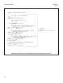
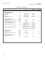
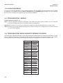
About This Document
This manual contains instructions for installation and operation of the Model 5081-P Two-Wire
pH/ORP Transmitter. The following list provides notes concerning all revisions of this document.
Rev. Level
Date
Notes
A
10/04
This is the initial release of the product manual. The manual has been
reformatted to reflect the Emerson documentation style and updated to
reflect any changes in the product offering. This manual contains
information on HART Smart and FOuNdATiON Fieldbus versions of 5081-P.
B
3/05
updated FM dwg & sensor compatibility chart.
C
4/05
Fixed drawings that changed in pdf conversion.
d
2/06
Added drawings, pages 52-60.
E
11/07
Added Mcerts to page 2.
F
06/09
Page 136 phone # change
G
1/11
updated Enclosure specifiations, updated ©
H
11/12
Added Fieldbus specifications, updated iTK revision and CE certifications
Emerson Process Management
2400 Barranca Parkway
irvine, CA 92606 uSA
Tel: (949) 757-8500
Fax: (949) 474-7250
http://www.raihome.com
© Rosemount Analytical inc. 2012
MODEL 5081-P pH/ORP
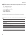
TABLE OF CONTENTS
MODEL 5081-P pH/ORP
TwO-wIRE TRANSMITTER
TABLE OF CONTENTS
Section
1.0
1.1
1.2
1.3
1.4
1.5
1.6
1.7
1.8
1.9
Title
DESCRIPTION AND SPECIFICATIONS ................................................................
Features and Applications........................................................................................
Specifications...........................................................................................................
Hazardous Location Approval ..................................................................................
Transmitter display during Calibration and Programming.......................................
infrared Remote Controller ......................................................................................
FOuNdATiON Fieldbus...............................................................................................
General Specifications .............................................................................................
HART Communications ...........................................................................................
Asset Management Solutions .................................................................................
Page
1
1
2
3
5
5
5
5
6
7
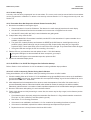
2.0
2.1
2.2
2.3
2.4
2.5
2.6
INSTALLATION ......................................................................................................
unpacking and inspection........................................................................................
Pre-installation Set up .............................................................................................
Orienting the display Board .....................................................................................
Mechanical installation.............................................................................................
Power Supply/Current Loop Wiring for Model 5081-P-HT .......................................
Power Supply Wiring for Model 5081-P-FF .............................................................
9
9
9
11
11
14
15
3.0
3.1
3.2
wIRING ...................................................................................................................
General information .................................................................................................
Wiring diagrams ......................................................................................................
16
16
17
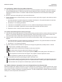
4.0
4.1
4.2
4.3
INTRINSICALLy SAFE AND ExPLOSION PROOF INSTALLATIONS .................
intrinsically Safe and Explosion-Proof installations for 5081-P-HT..........................
intrinsically Safe and Explosion-Proof installations for 5081-P-FF ..........................
intrinsically Safe and Explosion-Proof installations for 5081-P-Fi ...........................
31
32
40
48
5.0
5.1
5.2
5.3
5.4
5.5
5.6
5.7
5.8
OPERATION wITH REMOTE CONTROLLER ......................................................
Overview ..................................................................................................................
displays ...................................................................................................................
infrared Remote Controller (iRC) — Key Functions ................................................
Menu Tree - pH ........................................................................................................
diagnostic Messages - pH .......................................................................................
Menu Tree -ORP......................................................................................................
diagnostic Messages - ORP....................................................................................
Security ....................................................................................................................
55
55
56
57
58
58
60
60
62
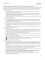
6.0
6.1
6.2
6.3
OPERATION wITH MODEL 375 ............................................................................
Note on Model 375 or 475 HART Communicator ....................................................
Connecting the HART Communicator......................................................................
Operation .................................................................................................................
63
63
63
64
Continued on the following page
i
MODEL 5081-P pH/ORP
TABLE OF CONTENTS
TABLE OF CONTENTS CONT’D
7.0
7.1
7.2
7.3
7.4
7.5
7.6
7.7
CALIBRATION OF pH MEASUREMENTS .............................................................
General ....................................................................................................................
Entering and Leaving the Calibrate Menu................................................................
using the Hold Function...........................................................................................
Temperature Calibration...........................................................................................
Auto Calibration .......................................................................................................
Manual Calibration ...................................................................................................
Making the Transmitter Reading Match a Second pH Meter (Standardization).......
69
69
69
69
70
71
73
75
8.0
8.1
8.2
8.3
8.4
8.5
8.6
8.7
8.8
8.9
PROGRAMMING FOR pH MEASUREMENTS.......................................................
General ....................................................................................................................
Entering and Leaving the Program Menu ................................................................
Output Ranging........................................................................................................
diagnostic Parameters.............................................................................................
Temperature Related Settings .................................................................................
display units ............................................................................................................
Buffer Calibration Parameters..................................................................................
isopotential Parameters ...........................................................................................
Generating a Test Current........................................................................................
77
77
77
79
80
84
86
87
89
91
9.0
9.1
9.2
9.3
9.4
9.5
CALIBRATION OF ORP MEASUREMENTS ..........................................................
General ....................................................................................................................
Entering and Leaving the Calibrate Menu................................................................
using the Hold Function...........................................................................................
Temperature Calibration...........................................................................................
Standardization ........................................................................................................
92
92
92
92
93
94
10.0
10.1
10.2
10.3
10.4
10.5
10.6
10.7
PROGRAMMING FOR ORP MEASUREMENTS ....................................................
General ....................................................................................................................
Entering and Leaving the Program Menu ................................................................
Output Ranging........................................................................................................
Temperature Element...............................................................................................
display units ............................................................................................................
diagnostic Parameters.............................................................................................
Generating a Test Current........................................................................................
95
95
95
97
99
100
101
104
11.0
11.1
11.2
11.3
11.4
11.5
MAINTENANCE ......................................................................................................
Overview ..................................................................................................................
Transmitter Maintenance .........................................................................................
pH Sensor Maintenance ..........................................................................................
ORP Sensor Maintenance .......................................................................................
Calibration................................................................................................................
105
105
105
106
108
108
Continued on the following page
ii
MODEL 5081-P pH/ORP
TABLE OF CONTENTS
TABLE OF CONTENTS CONT’D
12.0
12.1
12.2
12.3
12.4
12.5
12.6
12.7
12.8
TROUBLESHOOTING ...........................................................................................
Warning and Fault Messages ..................................................................................
Calibration Errors .....................................................................................................
Troubleshooting - General .......................................................................................
Troubleshooting When a diagnostic Message is Showing ......................................
Troubleshooting When No diagnostic Message is Showing....................................
displaying diagnostic Variables...............................................................................
Testing the Transmitter by Simulating pH ................................................................
Factory Assistance and Repairs ..............................................................................
109
109
110
110
110
122
127
127
130
13.0
13.1
13.2
13.3
13.4
13.5
13.6
13.7
13.8
13.9
13.10
13.11
pH MEASUREMENTS.............................................................................................
General ....................................................................................................................
Measuring Electrode ................................................................................................
Reference Electrode ................................................................................................
Liquid Junction Potential ..........................................................................................
Converting Voltage to pH .........................................................................................
Glass Electrode Slope .............................................................................................
Buffers and Calibration ............................................................................................
isopotential pH .........................................................................................................
Junction Potential Mismatch ....................................................................................
Sensor diagnostics ..................................................................................................
Shields, insulation, and Preamplifiers......................................................................
131
131
132
132
133
133
134
134
135
135
136
136
14.0
14.1
14.2
14.3
14.4
14.5
14.6
14.7
14.8
ORP MEASUREMENTS..........................................................................................
General ....................................................................................................................
Measuring Electrode ................................................................................................
Reference Electrode ................................................................................................
Liquid Junction Potential ..........................................................................................
Relating Cell Voltage to ORP...................................................................................
ORP, Concentration, and pH....................................................................................
interpreting ORP Measurements .............................................................................
Calibration................................................................................................................
137
137
138
138
138
139
139
140
142
15.0
15.1
15.2
15.3
THEORy — REMOTE COMMUNICATIONS...........................................................
Overview of HART Communications........................................................................
HART interface devices...........................................................................................
Asset Management Solutions ..................................................................................
143
143
143
144
16.0
RETURN OF MATERIAL.........................................................................................
145
iii
MODEL 5081-P pH/ORP
TABLE OF CONTENTS
LIST OF FIGURES
Number
1-1
1-2
1-3
1-4
1-5
2-1
2-2
2-3
2-4
2-5
2-6
3-1
3-2
3-3
3-4
3-5
3-6
3-7
3-8
3-9
3-10
3-11
3-12
3-13
3-14
3-15
3-16
3-17
Title
Page
Transmitter display during Calibration and Programming .......................................
5
infrared Remote Controller.......................................................................................
5
Configuring Model 5081 Transmitter with FOuNdATiON Fieldbus .............................
6
HART Communicator ...............................................................................................
7
AMS Main Menu Tools .............................................................................................
8
Mounting the Model 5081-P pH/ORP Transmitter on a Flat Surface........................
12
using the Pipe Mounting Kit to Attach the Model 5081-P pH/ORP to a pipe............
13
Load/Power Supply Wiring .......................................................................................
14
Model 5081-P-HT Power Wiring details...................................................................
14
Typical Fieldbus Network Electrical Wiring Configuration ........................................
15
Model 5081-P-FF Power Wiring details ...................................................................
15
Wiring and Preamplifier Configurations for pH and ORP Sensors ...........................
16
Wire Functions for Models 399-02, 399-09, 381pH-30-41, and 381pHE-31-41
before removing BNC and terminating cable ...........................................................
20
Wire Functions for Models 399-02, 399-09, 381pH-30-41, and 381pHE-31-41
after removing BNC and terminating cable. Wire Functions for Models
399-09-10-62, 381pH-30-42, and 381pHE-31-42 as received .................................
20
Wiring diagram for Models 399-02, 399-09, 381pH-30-41, and 381pHE-31-41
after removing BNC and terminating cable. Wiring diagram for Models 399-09-10-62,
381pH-30-42, and 381pHE-31-42 as received. Wiring directly to the transmitter ....
20
Wiring diagram for Models 399-02, 399-09, 381pH-30-41 after removing BNC
and terminating cable. Wiring diagram for Model 399-09-10-62, 381pH-30-42, and
381pH-31-42 as received. Wiring through a remote junction box to the transmitter
20
Wire Functions for Models 397-50, 397-54, 396-50, 396-54, 396R-50-60, 396R-54-60,
389-02-50, and 389-02-54 before removing BNC and terminating cable.................
21
Wire Functions for Models 397-50, 397-54, 369-50, 396-54, 396R-50-60, 396R-54-60,
389-02-50, and 389-02-54 after removing BNC and terminating cable. Wire
Functions for Models 397-54-62, 396-02-62, and 389-02-54-62 as received ..........
21
Wiring diagram for Models 397-50, 397-54, 369-50, 396-54, 389-02-50, and.........
389-02-54 after removing BNC and terminating cable. Wiring diagram for Models
397-54-62, 396-02-62, and 389-02-54-62 as received. Wiring directly to the
Transmitter
....................................................................................................
21
Wiring diagram for Models 397-50, 397-54, 369-50, 396-54, 396R-50-60, 396R-54-60,
389-02-50, and 389-02-54 after removing BNC and terminating cable. Wiring
diagram for Models 397-54-62, 396-02-62, and 389-02-54-62 as received.
Wiring Through a Remote Junction Box to the Transmitter .....................................
21
Wire Functions for Models 396R-50, 396R-54, 396R-50-61, 396P-02-50, 396P-02-54,
396P-05-55, 385+-04, and 385+-41-52....................................................................
22
Wiring diagram for Models 396R-50, 396R-54, 396R-50-61, 396P-02-50, 396P-02-54,
396P-05-55, 385+-04, and 385+-41-52. Wiring directly to the Transmitter ............
22
Wiring diagram for Models 396R-50, 396R-54, 396R-54-61, 396P-02-50, 396P-02-54,
396P-02-55, 385+-04, and 385+-41-52. Wiring Through a Sensor-Mounted
Junction Box to the Transmitter ...............................................................................
22
Wire Functions for Models 396P-01-55, 385+-03, 381+-40-55, and 381+-43-55 ....
23
Wiring diagram for Models 396P-01-55, 385+-03, 381+-40-55, and 381+-43-55....
23
Wire Functions for Model 328A-07...........................................................................
24
Wiring diagram for Models 328A and 385+-02 ........................................................
24
Wiring diagram for Model 385+-02 ..........................................................................
24
iv
MODEL 5081-P pH/ORP
TABLE OF CONTENTS
LIST OF FIGURES - CONT’D
Number
3-18
3-19
3-20
3-21
4-1
4-2
4-3
4-4
4-5
4-6
4-7
4-8
4-9
4-10
4-11
4-12
4-13
4-14
4-15
4-16
4-17
4-18
4-19
5-1
5-2
5-3
5-4
5-5
5-6
5-7
5-8
6-1
6-2
8-1
8-2
8-3
10-1
10-2
11-1
12-1
12-2
12-3
12-4
12-5
12-6
Title
Wiring diagram for Model 320HP-10-55 ..................................................................
Wiring diagram for Model 320HP-10-58 ..................................................................
Procedure for Removing BNC Connector and Preparing Coaxial Cable for
Connection to the Model 5081-P pH/ORP Transmitter.............................................
Preparation of Raw Connecting Cable .....................................................................
Model 5081-P-HT infrared Remote Control — CSA, FM, & ATEX approvals ..........
Model 5081-P-FF infrared Remote Control — CSA, FM, & ATEX approvals...........
FM Explosion-Proof installation for Model 5081-P-HT .............................................
FM intrinsically Safe Label for Model 5081-P-HT.....................................................
FM intrinsically Safe installation for Model 5081-P-HT ............................................
CSA intrinsically Safe Label for Model 5081-P-HT...................................................
CSA intrinsically Safe installation for Model 5081-P-HT ..........................................
ATEX intrinsically Safe Label for Model 5081-P-HT.................................................
FM Explosion-Proof installation for Model 5081-P-FF .............................................
FM intrinsically Safe Label for Model 5081-P-FF .....................................................
FM intrinsically Safe installation for Model 5081-P-FF.............................................
CSA intrinsically Safe Label for Model 5081-P-FF ...................................................
CSA intrinsically Safe installation for Model 5081-P-FF...........................................
ATEX intrinsically Safe Label for Model 5081-P-FF .................................................
FM intrinsically Safe Label for Model 5081-P-Fi ......................................................
FM intrinsically Safe installation for Model 5081-P-Fi..............................................
CSA intrinsically Safe Label for Model 5081-P-Fi ....................................................
CSA intrinsically Safe installation for Model 5081-P-Fi............................................
ATEX intrinsically Safe Label for Model 5081-P-Fi ..................................................
Functional Block diagram for the Model 5081-P pH/ORP Transmitter with
FOuNdATiON Fieldbus .............................................................................................
Process display Screen ...........................................................................................
Program display Screen ..........................................................................................
infrared Remote Controller.......................................................................................
pH Menu Tree for Model 5081-P-HT ........................................................................
pH Menu Tree for Model 5081-P-FF .......................................................................
ORP Menu Tree for Model 5081-P-HT ....................................................................
ORP Menu Tree for Model 5081-P-FF ....................................................................
Connecting the HART Communicator .....................................................................
5081-P-HT HART / Model 375 Menu Tree ...............................................................
Suggested Glass impedance Warning and Failure Limits .......................................
Suggested Warning and Failure Limits for Low impedance Reference Electrodes .
Suggested Warning and Failure Limits for High impedance Glass Reference Electrodes
Suggested Warning and Failure Limits for Low impedance Reference Electrodes .
Suggested Glass impedance Warning and Failure Limits for a Glass Reference
Electrode ..................................................................................................................
Checking the Potential of the Reference Electrode..................................................
Warning Annunciation...............................................................................................
Fault Annunciation....................................................................................................
Three-Wire RTd ....................................................................................................
Temperature Simulation into the Model 5081-P pH/ORP Transmitter ......................
pH Simulation When the Preamplifier is Located in the Transmitter ........................
pH Simulation When the Preamplifier is Located in a Remote Junction Box or
in a Sensor-Mounted Junction Box ..........................................................................
v
Page
25
25
26
27
31
31
32
33
34
36
37
39
40
41
42
44
45
47
48
49
51
52
54
55
56
56
57
58
59
60
61
63
65
80
81
81
101
101
107
109
109
116
116
128
128
MODEL 5081-P pH/ORP
TABLE OF CONTENTS
LIST OF FIGURES - CONT’D
12-7
13-1
13-2
13-3
13-4
13-5
13-6
13-7
13-8
14-1
14-2
14-3
14-4
14-5
14-6
15-1
15-2
Simulate pH Through Model 381+ Sensor Preamplifier ...........................................
pH Measurement Cell...............................................................................................
Measuring Electrode (pH) ........................................................................................
Cross-Section Through the pH Glass.......................................................................
Reference Electrode.................................................................................................
The Origin of Liquid Junction Potential.....................................................................
Glass Electrode Slope..............................................................................................
Two-Point Buffer Calibration.....................................................................................
Liquid Junction Potential Mismatch ..........................................................................
ORP Measurement Cell ...........................................................................................
Measuring Electrode (ORP) .....................................................................................
Reference Electrode.................................................................................................
The Origin of Liquid Junction Potential.....................................................................
Electrode Potential ...................................................................................................
ORP Measurement interpretation ............................................................................
HART Communications ............................................................................................
AMS Main Menu Tools .............................................................................................
129
131
132
132
133
133
134
136
136
137
138
138
139
139
140
143
144
LIST OF TABLES
Number Title
3-1
3-2
3-3
3-4
3-5
3-6
3-7
3-8
3-9
3-10
3-11
8-1
8-2
8-3
8-4
10-1
11-1
12-1
Page
Wiring diagrams for Model 399 Sensors..................................................................
Wiring diagrams for Model 397 Sensors..................................................................
Wiring diagrams for Model 396R Sensors ...............................................................
Wiring diagrams for Model 396P Sensors ...............................................................
Wiring diagrams for Model 396 Sensors..................................................................
Wiring diagrams for Model 389 Sensors..................................................................
Wiring diagrams for Model 385+ Sensors................................................................
Wiring diagrams for Model 381+ Sensors................................................................
Wiring diagrams for Model 381pHE and 381pH Sensors ........................................
Wiring diagrams for Model 328A Sensors ...............................................................
Wiring diagrams for Model 320HP Sensors.............................................................
pH Settings List .......................................................................................................
pH Values of Standard Buffer Solutions and the Temperature Range over which
pH Values are defined .............................................................................................
pH Values of Commercial (technical) Buffers and the Temperature Range over
which pH Values are defined ..................................................................................
Standard and Technical Buffers Recognized by the Model 5081-P pH Transmitter
ORP Settings List ....................................................................................................
Replacement Parts for Model 5081-P pH Transmitter .............................................
RTd Resistance Values ...........................................................................................
vi
17
17
17
18
18
18
19
19
19
19
19
78
87
88
88
96
106
116
MODEL 5081-P pH/ORP
SECTION 1.0
DESCRIPTION AND SPECIFICATIONS
SECTION 1.0
DESCRIPTION AND SPECIFICATIONS
• CHOiCE OF COMMuNiCATiON PROTOCOL: HART® or FOuNdATiON Fieldbus.
• LARGE, EASY-TO-REAd two-line display shows the process measurement and temperature.
• SiMPLE MENu STRuCTuRE.
• ROBuST NEMA 4X ENCLOSuRE.
• iNTRiNSiCALLY SAFE dESiGN allows the transmitter to be used in hazardous environments
(with appropriate safety barriers).
• NON-VOLATiLE MEMORY retains program settings and calibration data during power failures.
• CHANGiNG FROM pH TO ORP operation takes only seconds.
• AuTOMATiC TWO-POiNT BuFFER CALiBRATiON reduces errors.
• SOLuTiON TEMPERATuRE COMPENSATiON converts measured pH to the pH at 25°C.
• CONTiNuOuS diAGNOSTiCS monitor sensor performance and warn the user of failure (FAuLT)
or approaching failure (WARNiNG).
1.1 FEATURES AND APPLICATIONS
The Model 5081 family of transmitters can be used to
measure pH or ORP in a variety of process liquids. The
5081 is compatible with most Rosemount Analytical sensors. See the Specifications section for details.
A handheld infrared remote controller or the HART Model
375 communicator can also be used for programming and
calibrating the transmitter. The remote controller works
from as far away as six feet.
The transmitter has a rugged, weatherproof, corrosionresistant enclosure (NEMA 4X and iP65) of epoxy-painted
aluminum. The enclosure also meets explosion-proof
standards.
The Model 5081-P Transmitter with the appropriate sensor
can be configured for either pH or ORP (oxidation reduction potential) measurement of aqueous solutions. Housed
in a NEMA 4X case, the Model 5081 can be located close
to the sensor even in the harshest environments, including
process, water or wastewater monitoring.
The transmitter has a two-line seven-segment display.
The main measurement appears in 0.8-inch (20 mm) high
numerals. The secondary measurement, temperature
(and pH if free chlorine is being measured), appears in
0.3-inch (7 mm) high digits.
Two digital communication protocols are available: HART
(model option -HT) and Foundation Fieldbus (model
option -FF). digital communications allows access to AMS
(Asset Management Solutions). use AMS to set up and
configure the transmitter, read process variables, and
troubleshoot problems from a personal computer or host
anywhere in the plant.
Advanced features include automatic 2-point buffer calibration routine, automatic recognition of Pt100 or Pt1000
RTd, and menu-selected internal preamplifier. Predictive
sensor diagnostic capability is possible through the
impedance measurement of the pH glass membrane and
reference electrode, fully supported by AMS. Solution
temperature calibration allows the instrument to calculate
and display the pH at 25°C when the temperature coefficient of the measured liquid is provided.
1
MODEL 5081-P pH/ORP
SECTION 1.0
DESCRIPTION AND SPECIFICATIONS
1.2 SPECIFICATIONS
1.2.1 GENERAL SPECIFICATIONS
Housing: Cast aluminum with epoxy coating. NEMA 4X
(iP65). Neoprene O-ring cover seals.
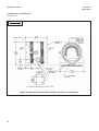
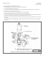
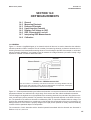
Dimensions: 160.5 mm x 175.3 mm x 161.3 mm (6.3 in.
x 6.9 in. x 6.4 in.) See drawing.
Conduit Openings: ¾-in. FNPT
Ambient Temperature: -4 to 149°F (-20 to 65°C)
Storage Temperature: -22 to 176°F (-30 to 80°C)
Relative Humidity: 0 to 95% (non-condensing)
weight/Shipping weight: 10 lb/10 lb (4.5/5.0 kg)
HART option
Display: Two-line LCd; first line shows process variable
(pH, ORP, conductivity, % concentration, oxygen,
ozone, or chlorine), second line shows process temperature and output current. For pH/chlorine combination, the second line can be toggled to show pH. Fault
and warning messages, when triggered, alternate with
temperature and output readings.
Power & Load Requirements: A power supply voltage of
9-32 Vdc at 22 mA is required.
First line: 7 segment LCd, 0.8 in. (20 mm) high.
pH Range: 0 to 14
FOUNDATION FIELDBUS —
1.2.2 FUNCTIONAL SPECIFICATIONS
Second line: 7 segment LCd, 0.3 in. (7mm) high.
ORP Range: -1400 to +1400mV
display board can be rotated 90 degrees clockwise or
counterclockwise.
Calibrations/standardization: The automatic buffer
recognition uses stored buffer values and their temperature curves for the most common buffer standards
available worldwide. The transmitter also performs a
stabilization check on the sensor in each buffer.
during calibration and programming, messages and
prompts appear in the second line.
Temperature resolution: 0.1°C
Hazardous Location Approval: For details, see specifications for the measurement of interest.
RFI/EMI: EN-61326
Digital Communications:
Sira MC070112/00
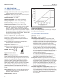
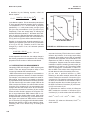
HART —
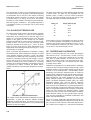
Power & Load Requirements:
Supply voltage at the transmitter terminals should be at
least 12 Vdc. Power supply voltage should cover the voltage drop on the cable plus the external load resistor
required for HART communications (250 W minimum).
Minimum power supply voltage is 12 Vdc. Maximum
power supply voltage is 42.4 Vdc (30 Vdc for intrinsically
safe operation). The graph shows the supply voltage
required to maintain 12 Vdc (upper line) and 30 Vdc
(lower line) at the transmitter terminals when the current is
22 mA.
Analog Output: Two-wire, 4-20 mA output with superimposed HART digital signal. Fully scalable over the
operating range of the sensor.
Output accuracy: ±0.05 mA
2
A manual two-point calibration is made by immersing
the sensor in two different buffer solutions and entering the pH values. The microprocessor automatically
calculates the slope which is used for self-diagnostics.
An error message will be displayed if the pH sensor is
faulty. This slope can be read on the display and/or
manually adjusted if desired.
An on-line one-point process standardization is
accomplished by entering the pH or ORP value of a
grab sample as measured by a lab reference.
Preamplifier Location: A preamplifier must be used to
convert the high impedance pH electrode signal to a
low impedance signal for transmitter use. The integral
preamplifier of the Model 5081-P may be used when
the sensor to transmitter distance is less than 15 ft
(4.5 m). Locate the preamplifier in the sensor or junction box for longer distances.
Automatic Temperature Compensation: External 3 or 4
wire Pt 100 RTd or Pt 1000 RTd located in the sensor, compensates the pH reading for temperature fluctuations. Compensation covers the range -15 to 130°C
(5 to 270°F). Manual temperature compensation is
also selectable.
MODEL 5081-P pH/ORP
SECTION 1.0
DESCRIPTION AND SPECIFICATIONS
Accuracy: ± 1 mV @ 25°C ± 0.01 pH
Repeatability: ± 1 mV @ 25°C ± 0.01 pH
Stability: 0.25% / year @ 25°C
Diagnostics: The internal diagnostics can detect:
Calibration Error
Low Temperature Error
High Temperature Error
Sensor Failure
Line Failure
CPu Failure
ROM Failure
input Warning
Glass Failure
Glass Warning
Reference Failure
Reference Warning
Once one of the above is diagnosed, the LCd will display a message describing the failure/default detected.
Digital Communications as applicable by model:
HART (pH): PV assigned to pH. SV, TV, and 4V assignable to pH, temperature, mV, glass impedance, reference
impedance, or RTd resistance.
HART (ORP): PV assigned to ORP. SV, TV, and 4V assignable to ORP, temperature, reference impedance, or RTd
resistance.
Fieldbus (pH): Four Ai blocks assigned to pH, temperature, reference impedance, and glass impedance.
Fieldbus (ORP): Three Ai blocks assigned to ORP, temperature, and reference impedance.
1.3 HAzARDOUS LOCATION APPROvAL
Non-Incendive:
Intrinsic Safety:
Class i, ii, iii, div. 1
Class i, div. 2, Groups A-d
Groups A-G
dust ignition Proof
T4
Class ii & iii, div. 1, Groups E-G
Tamb = 70°C
NEMA 4X Enclosure
Exia Entity
Class i, Groups A-d
Class i, div. 2, Groups A-d
Class ii, Groups E-G
Suitable for
Class iii
Class ii, div. 2, Groups E-G
T4
T4
Tamb = 70°C
Tamb = 70°C
iECEx BAS 09.0159X
Ex ia iiC T4 Ga
ATEx
Explosion-Proof:
Class i, div. 1, Groups B-d
0600 ii 1 G
Baseefa02ATEX1284
Class ii, div. 1, Groups E-G
Class iii, div. 1
EEx ia iiC T4
Tamb = -20°C to +65°C
ATEx and IECEx Special Conditions for Use: The model
5081 enclosure is made of aluminum alloy and is given a protective polyurethane paint finish. However, care should be taken
to protect it from impact or abrasion if located in a zone 0 hazardous area.
Class i, Groups B-d
Class ii, Groups E-G
Class iii
Tamb = 65°C max
3
MODEL 5081-P pH/ORP
SECTION 1.0
DESCRIPTION AND SPECIFICATIONS
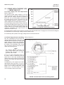
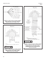
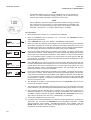
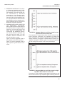
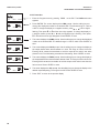
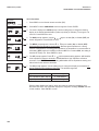
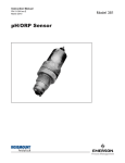
1.4 TRANSMITTER DISPLAy DURING
CALIBRATION AND PROGRAMMING
(FIGURE 1-1)
1. Continuous display of pH, ORP, conductivity,
oxygen, chlorine, or ozone reading.
2. units: pH, mV, µS/cm, mS/cm, ppm, ppb,
% saturation, or %.
3. Current menu section appears here.
4. Submenus, prompts, and diagnostic readings
appear hear.
5. Commands available in each submenu or at
each prompt appear here.
6. Hold appears when the transmitter is in hold.
7. Fault appears when the transmitter detects a
sensor or instrument fault.
8.
© flashes during HART digital communication.
FIGURE 1-1. TRANSMITTER DISPLAy DURING
CALIBRATION AND PROGRAMMING
The program display screen allows access to calibration and
programming menus.
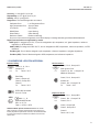
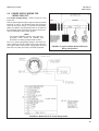
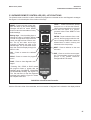
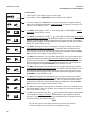
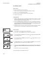
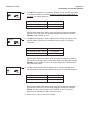
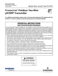
1.5 INFRARED REMOTE CONTROLLER
(FIGURE 1-2)
4.
1. Pressing a menu key allows the user access to
calibrate, program, or diagnostic menus.
2. Press ENTER to store data and settings. Press
NEXT to move from one submenu to the next.
Press EXiT to leave without storing changes.
3. use the editing arrow keys to scroll through lists
of allowed settings or to change a numerical setting to the desired value.
3.
1.
2.
4. Pressing HOLd puts the transmitter in hold and
sends the output current to a pre-programmed
value. Pressing RESET causes the transmitter
to abandon the present menu operation and
return to the main display.
FIGURE 1-2. INFRARED REMOTE CONTROLLER
4
MODEL 5081-P pH/ORP
SECTION 1.0
DESCRIPTION AND SPECIFICATIONS
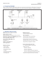
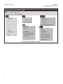
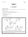
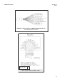
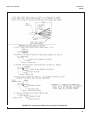
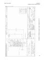
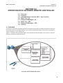
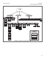
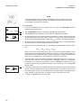
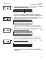
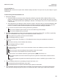
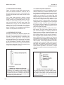
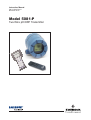
1.6 FOUNDATION FIELDBUS
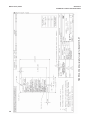
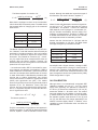
Figure 1-3 shows a 5081-P-FF being used to measure and control pH and chlorine levels in drinking water. The figure also
shows three ways in which Fieldbus communication can be used to read process variables and configure the transmitter.
FIGURE 1-3. CONFIGURING MODEL 5081-P TRANSMITTER wITH FOUNDATION FIELDBUS
1.7 GENERAL SPECIFICATIONS
Model: 5081-P-FF pH Fieldbus Transmitter
Additional Features:
Type: pH/ORP Transmitter
• Common Software download
Device ITK Profile: 6 (Released for iTK 6.0.0 / 6.0.1)
• Block instantiation
Manufacturer Identification (MANUFAC_ID): 0x524149
• Supports deltaV Auto Commissioning
Device Type (DEv_TyPE): 0x4085
• Supports deltaV Auto Replacement
Device Revision (DEv_REv): 0x03
• Supports deltaV Firmware Live download
Linkmaster: Yes
• PlantWeb Alerts with re-annunciation / multibit
Number of Link Objects: 20
• Supports Easy Configuration Assistant
vCR’s supported: 20
Function Blocks (Execution Time):
Mandatory Features:
• 4 – Analog input Blocks (15 mseconds)
• Resource Block
• Ai Block Channels:
• Alarm and Events
Channel 1: pH, ORP
• Function Block Linking
Channel 2: Temperature
• Trending
Channel 3: Reference Electrode impedance
• Multi-Bit Alert Reporting
Channel 4: Glass Electrode impedance (pH only)
• Field diagnostics
• Proportional integral derivative (25 mseconds)
5
MODEL 5081-P pH/ORP
SECTION 1.0
DESCRIPTION AND SPECIFICATIONS
Power:
• Two Wire device; Fieldbus Polarity insensitive
• Current draw: 21 mA
• device Certifications: iS / FiSCO
• Maximum certified input Voltage for iS: 30V
• Maximum certified input current for iS: 300mA
• Maximum certified input power for iS: 1.3W
• internal Capacitance (Ci): 0 nF
• internal inductance (Li): 0 μH
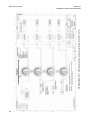
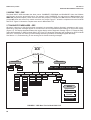
1.8 HART COMMUNICATIONS
1.8.1 OvERvIEw OF HART COMMUNICATION
HART (highway addressable remote transducer) is a digital communication system in which two frequencies are superimposed on the 4 to 20 mA output signal from the transmitter. A 1200 Hz sine wave represents the digit 1, and a 2400 Hz
sine wave represents the digit 0. Because the average value of a sine wave is zero, the digital signal adds no dc component to the analog signal. HART permits digital communication while retaining the analog signal for process control.
The HART protocol, originally developed by Fisher-Rosemount, is now overseen by the independent HART
Communication Foundation. The Foundation ensures that all HART devices can communicate with one another. For more
information about HART communications, call the HART Communication Foundation at (512) 794-0369. The internet
address is http://www.hartcomm.org.
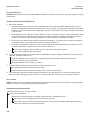
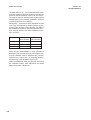
1.8.2 HART INTERFACE DEvICES
HART communicators allow the user to view measurement data (pH, ORP and temperature), program the transmitter, and
download information from the transmitter for transfer to a computer for analysis. downloaded information can also be sent
to another HART transmitter. Either a hand-held communicator, such as the Rosemount Model 375, or a computer can be
used. HART interface devices operate from any wiring termination point in the 4 - 20 mA loop. A minimum load of 250 ohms
must be present between the transmitter and the power supply. See Figure 1-4.
if your communicator does not recognize the Model 5081 pH/ORP transmitter, the device description library may need
updating. Call the manufacturer of your HART communication device for updates.
6
MODEL 5081-P pH/ORP
SECTION 1.0
DESCRIPTION AND SPECIFICATIONS
4-20 mA + digital
250
ohm
Model 5081-P
Two-wire
Transmitter
Control System
Hand Held
Communicator
(“Configurator”)
Bridge
Computer
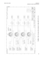
FIGURE 1-4. HART Communicators.
Both the Rosemount Model 375 (or 475) and a computer can be used to communicate
with a HART transmitter. The 250 ohm load (minimum) must be present between the
transmitter and the power supply.
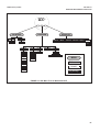
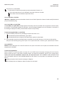
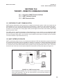
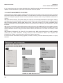
1.9 ASSET MANAGEMENT SOLUTIONS
Asset Management Solutions (AMS) is software that helps plant personnel better monitor the performance of analytical
instruments, pressure and temperature transmitters, and control valves. Continuous monitoring means maintenance personnel can anticipate equipment failures and plan preventative measures before costly breakdown maintenance is
required.
AMS uses remote monitoring. The operator, sitting at a computer, can view measurement data, change program settings,
read diagnostic and warning messages, and retrieve historical data from any HART-compatible device, including the Model
5081-P transmitter. Although AMS allows access to the basic functions of any HART compatible device, Rosemount
Analytical has developed additional software for that allows access to all features of the Model 5081-P transmitter.
AMS can play a central role in plant quality assurance and quality control. using AMS Audit Trail, plant operators can track
calibration frequency and results as well as warnings and diagnostic messages. The information is available to Audit Trail
whether calibrations were done using the infrared remote controller, the Model 375 HART communicator, or AMS software.
AMS operates in Windows 95. See Figure 1-5 for a sample screen. AMS communicates through a HART-compatible
modem with any HART transmitters, including those from other manufacturers. AMS is also compatible with
FOuNdATiONÔ Fieldbus, which allows future upgrades to Fieldbus instruments.
Rosemount Analytical AMS windows provide access to all transmitter measurement and configuration variables. The
user can read raw data, final data, and program settings and can reconfigure the transmitter from anywhere in the plant.
Figures 1-6 and 1-7 show two of the many configuration and measurement screens available using HART AMS. Figure
1-8 shows a configuration screen available through AMS inside using FOuNdATiON Fieldbus.
7
MODEL 5081-P pH/ORP
SECTION 1.0
DESCRIPTION AND SPECIFICATIONS
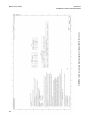
FIGURE 1-5. AMS MAIN MENU TOOLS
8
MODEL 5081-P pH/ORP
SECTION 2.0
INSTALLATION
SECTION 2.0
INSTALLATION
2.1
2.2
2.3
2.4
2.5
Unpacking and Inspection
Pre-Installation Set Up
Orienting the Display Board
Mechanical Installation
Power Supply wiring
2.1 UNPACKING AND INSPECTION
inspect the shipping container. if it is damaged, contact the shipper immediately for instructions. Save the box. if there is
no apparent damage, remove the transmitter. Be sure all items shown on the packing list are present. if items are missing, immediately notify Rosemount Analytical.
Save the shipping container and packaging. They can be reused if it is later necessary to return the transmitter to the factory.
2.2 PRE-INSTALLATION SETUP
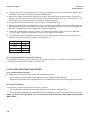
2.2.1 Temperature Element
The Model 5081-P pH/ORP transmitter is compatible with sensors having Pt 100 and Pt 1000. Sensors from other manufacturers may have a Pt 1000 RTd. For Rosemount Analytical sensors, the type of temperature element in the sensor is
printed on the tag attached to the sensor cable. For the majority of sensors manufactured by Rosemount Analytical, the
RTd iN lead is red and the RTd RTN lead is white. The Model 328A sensor has no RTd. The Model 320HP system has
a readily identifiable separate temperature element. Resistance at room temperature for common RTds is given in the
table.
if the resistance is...
about 110 ohms
about 1100 ohms
the temperature element is a
Pt 100 RTd
Pt 1000 RTd
2.2.2 Reference Electrode Impedance
The standard silver-silver chloride reference electrode used in most industrial and laboratory pH electrodes is low impedance. EVERY pH and ORP sensor manufactured by Rosemount Analytical has a low impedance reference. Certain specialized applications require a high impedance reference electrode. The transmitter must be re-programmed to recognize
the high impedance reference.
9
MODEL 5081-P pH/ORP
SECTION 2.0
INSTALLATION
2.2.3 Preamplifier Location
pH sensors produce a high impedance voltage signal that must be preamplified before use. The signal can be preamplified before it reaches the transmitter or it can be preamplified in the transmitter. To work properly, the transmitter must know
where preamplification occurs. Although ORP sensors produce a low impedance signal, the voltage from an ORP sensor
is amplified the same way as a pH signal.
if the sensor is wired to the transmitter through a junction box, the preamplifier is ALWAYS in either the junction box or the
sensor. Junction boxes can be attached to the sensor or installed some distance away. if the junction box is not attached
to the sensor, it is called a remote junction box. in most junction boxes used with the Model 5081-P pH/ORP, a flat, black
plastic box attached to the same circuit board as the terminal strips houses the preamplifier. The preamplifier housing in
the 381+ sensor is crescent shaped.
if the sensor is wired directly to the transmitter, the preamplifier can be in the sensor or in the transmitter. if the sensor
cable has a GREEN wire, the preamplifier is in the sensor. if there is no green wire, the sensor cable will contain a coaxial cable. A coaxial cable is an insulated wire surrounded by a braided metal shield. depending on the sensor model, the
coaxial cable terminates in either a BNC connector or in a separate ORANGE wire and CLEAR shield.
10
MODEL 5081-P pH/ORP
SECTION 2.0
INSTALLATION
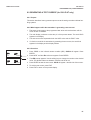
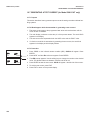
2.3 ORIENTING THE DISPLAy BOARD
The display board can be rotated 90 degrees, clockwise or counterclockwise, from the original position. To reposition the
display:
1. Loosen the cover lock nut until the tab disengages from the circuit end cap. unscrew the cap.
2. Remove the three bolts holding the circuit board stack.
3. Lift and rotate the display board 90 degrees, clockwise or counterclockwise, into the desired position.
4. Position the display board on the stand offs. Replace and tighten the bolts.
5. Replace the circuit end cap.
2.4 MECHANICAL INSTALLATION
2.4.1 General information
1. The transmitter tolerates harsh environments. For best results, install the transmitter in an area where temperature
extremes, vibrations, and electromagnetic and radio frequency interference are minimized or absent.
2. To prevent unintentional exposure of the transmitter circuitry to the plant environment, keep the security lock in place
over the circuit end cap. To remove the circuit end cap, loosen the lock nut until the tab disengages from the end cap,
then unscrew the cover.
3. The transmitter has two 3/4-inch conduit openings, one on each side of the housing. Run sensor cable through the left
side opening (as viewed from the wiring terminal end of the transmitter) and run power wiring through the right side
opening.
4. use weathertight cable glands to keep moisture out of the transmitter.
5. if conduit is used, plug and seal the connections at the transmitter housing to prevent moisture from getting inside the
transmitter.
NOTE
Moisture accumulating in the transmitter housing can affect the performance of the transmitter and may void the warranty.
6. if the transmitter is installed some distance from the sensor, a remote junction box with preamplifier in the junction box
or in the sensor may be necessary. Consult the sensor instruction manual for maximum cable lengths.
11
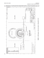
MODEL 5081-P pH/ORP
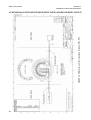
2.4.2 Mounting on a Flat Surface.
See Figure 2-1.
MILLIMETER
INCH
FIGURE 2-1. Mounting the Model 5081-P pH/ORP Transmitter on a Flat Surface
12
SECTION 2.0
INSTALLATION
MODEL 5081-P pH/ORP
SECTION 2.0
INSTALLATION
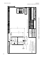
2.4.3 Pipe Mounting.
See Figure 2-2. The pipe mounting kit (PN 2002577) accommodates 1-1/2 to 2 in. pipe.
MILLIMETER
INCH
dWG. NO.
40308104
REV.
G
dWG. NO.
40308103
REV.
C
FIGURE 2-2. Using the Pipe Mounting Kit to Attach the Model 5081-P pH/ORP Transmitter to a Pipe
13
MODEL 5081-P pH/ORP
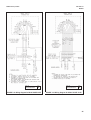
2.5
SECTION 2.0
INSTALLATION
POwER SUPPLy/CURRENT LOOP
— MODEL 5081-P-HT
2.5.1 Power Supply and Load Requirements.
Refer to Figure 2-3.
The minimum power supply voltage is 12.5 Vdc
and the maximum is 42.4 Vdc. The top line on the
graph gives the voltage required to maintain at
least 12.5 Vdc at the transmitter terminals when
the output signal is 22 mA. The lower line is the
supply voltage required to maintain a 30 Vdc terminal voltage when the output signal is 22 mA.
The power supply must provide a surge current during the first 80 milliseconds of start-up. For a 24 Vdc
power supply and a 250 ohm load resistor the surge
current is 40 mA. For all other supply voltage and
resistance combinations the surge current is not
expected to exceed 70 mA.
FIGURE 2-3. Load/Power Supply Requirements
For digital (HART or AMS) communications, the load must be at least 250 ohms. To supply the 12.5 Vdc lift off voltage at
the transmitter, the power supply voltage must be at least 18 Vdc.
For intrinsically safe operation the supply voltage should not exceed 30.0 Vdc.
2.5.2 Power Supply-Current Loop wiring. Refer to Figure 2-4.
Run the power/signal wiring through the
opening nearest terminals 15 and 16. use
shielded cable and ground the shield at the
power supply. To ground the transmitter,
attach the shield to the grounding screw on
the inside of the transmitter case. A third
wire can also be used to connect the transmitter case to earth ground.
NOTE
For optimum EMi/RFi immunity, the
power supply/output cable should be
shielded and enclosed in an earthgrounded metal conduit.
do not run power supply/signal wiring in
the same conduit or cable tray with AC
power lines or with relay actuated signal
cables. Keep power supply/ signal wiring at
least 6 ft (2 m) away from heavy electrical
equipment.
An additional 0-1 mA current loop is available between TB-14 and TB-15. A 1 mA current in this loop signifies a sensor fault. See
Figure 4-3 for wiring instructions. See
Section 8.4 or 10.6 and Section 12.0 for
more information about sensor faults.
FIGURE 2-4. Model 5081-P-HT Power wiring Details
14
MODEL 5081-P pH/ORP
2.6
SECTION 2.0
INSTALLATION
POwER SUPPLy wIRING FOR
MODEL 5081-P-FF
2.6.1 Power Supply wiring. Refer to Figure 2-5 and
Figure 2-6.
Run the power/signal wiring through the opening nearest
terminals 15 and 16. use shielded cable and ground the
shield at the power supply. To ground the transmitter,
attach the shield to the grounding screw on the inside of
the transmitter case. A third wire can also be used to connect the transmitter case to earth ground.
NOTE
For optimum EMi/RFi immunity, the power supply/output cable should be shielded and
enclosed in an earth-grounded metal conduit.
do not run power supply/signal wiring in the same conduit or cable tray with AC power lines or with relay actuated signal cables. Keep power supply/signal wiring at
least 6 ft (2 m) away from heavy electrical equipment.
5081-P pH/ORP
Transmitter
5081-P pH/ORP
Transmitter
FIGURE 2-5. Typical Fieldbus Network Electrical
wiring Configuration
FIGURE 2-6. Model 5081-P-FF Power wiring Details
15
MODEL 5081-P pH/ORP
SECTION 3.0
wIRING
SECTION 3.0
wIRING
3.1
3.2
General Information
wiring Diagrams
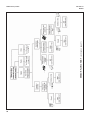
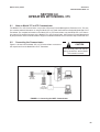
3.1 GENERAL INFORMATION
pH and ORP sensors manufactured by Rosemount Analytical can be wired to the Model 5081-P pH/ORP transmitter in
three ways:
1. directly to the transmitter,
2. to a sensor-mounted junction box and then to the transmitter,
3. to a remote junction box and then from the remote junction box to the transmitter.
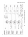
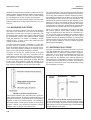
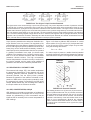
The pH (or ORP) signal can also be preamplified in one of four places.
1. in the sensor (a, d),
2. in a junction box mounted on the sensor (c),
3. in a remote junction box (e).
4. at the transmitter (b).
Figure 3-1 illustrates the various arrangements.
FIGURE 3-1. wiring and Preamplifier Configurations for pH and ORP Sensors.
The asterisk identifies the location of the preamplifier. in (a) and (b) the sensor is wired directly to the transmitter. The signal is amplified at the sensor (a) or at the transmitter (b). in (c) the sensor is wired through a sensor-mounted junction box to the transmitter.
The preamplifier is in the sensor-mounted junction box. in (d) and (e) the sensor is wired through a remote junction box to the transmitter. The preamplifier is located in the sensor (d) or the junction box (e).
16
MODEL 5081-P pH/ORP
SECTION 3.0
wIRING
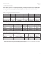
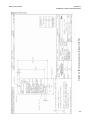
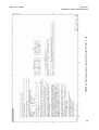
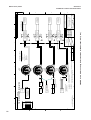
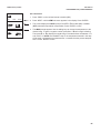
3.2 wIRING DIAGRAMS
Refer to Tables 3-1 through 3-11 to locate the appropriate wire function and wiring diagram. There is a separate table for
each model. The sensor models having the highest number appear first. if you do not know the model number of the
sensor, refer to the flow charts on pages 32 through 34. Only the model option numbers needed to select the correct wiring diagram are shown. Other numbers are not shown. For all other sensors, see sensor manual.
Table 3-1. wiring Diagrams for Model 399 sensors
Sensor
Junction Box
Preamplifier
RTD
wire Function
wiring Diagram
399-09*
none
in transmitter
Pt 100
Figure 3-2
Figure 3-4
399-09*
remote
in remote junction box
Pt 100
Figure 3-2
Figure 3-5
399-09-62
none
in transmitter
Pt 100
Figure 3-3
Figure 3-4
399-09-62
remote
in remote junction box
Pt 100
Figure 3-3
Figure 3-5
399-33 (ORP only)
none
in transmitter
Pt 100
Figure 3-19
Figure 3-20
Table 3-2 wiring Diagrams for Model 397 Sensors
Sensor
Junction Box
Preamplifier
RTD
wire Function
wiring Diagram
397-54*
none
in transmitter
Pt 100
Figure 3-6
Figure 3-8
397-54*
remote
in remote junction box
Pt 100
Figure 3-6
Figure 3-9
397-54-62
none
in transmitter
Pt 100
Figure 3-7
Figure 3-8
397-54-62
remote
in remote junction box
Pt 100
Figure 3-7
Figure 3-9
Table 3-3 wiring Diagrams for Model 396R Sensors
Sensor
Junction Box
Preamplifier
RTD
wire Function
wiring Diagram
396R-54
none
in transmitter
Pt 100
Figure 3-10
Figure 3-11
396R-54
remote
in remote junction box
Pt 100
Figure 3-10
Figure 3-12
396R-54-60
sensor-mounted
in sensor-mounted junction box
Pt 100
Figure 3-7
Figure 3-9
396R-54-61
sensor-mounted
in sensor-mounted junction box
Pt 100
Figure 3-10
Figure 3-12
* Sensors have a BNC connector that the Model 5081-P pH/ORP transmitter does not accept. Cut off the BNC and terminate
the coaxial cable as shown in Figure 3-23. Alternatively, use a BNC adapter.
17
MODEL 5081-P pH/ORP
SECTION 3.0
wIRING
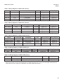
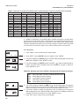
Table 3-4 wiring Diagrams for Model 396P Sensors
Sensor
Junction Box
Preamplifier
RTD
wire Function
wiring Diagram
396P-01-55
none
in sensor
Pt 100
Figure 3-13
Figure 3-14
396P-01-55
remote
in sensor
Pt 100
Figure 3-13
Figure 3-14
396P-02-54
none
in transmitter
Pt 100
Figure 3-10
Figure 3-11
396P-02-54
remote
in remote junction box
Pt 100
Figure 3-10
Figure 3-12
396P-02-55
none
in transmitter
Pt 100
Figure 3-10
Figure 3-11
396P-02-55
remote
in remote junction box
Pt 100
Figure 3-10
Figure 3-12
Table 3-5 wiring Diagrams for Model 396 Sensor
Sensor
Junction Box
Preamplifier
RTD
wire Function
wiring Diagram
396-54*
none
in transmitter
Pt 100
Figure 3-6
Figure 3-8
396-54*
remote
in remote junction box
Pt 100
Figure 3-6
Figure 3-9
396-54-62
none
in transmitter
Pt 100
Figure 3-7
Figure 3-8
396-54-62
remote
in remote junction box
Pt 100
Figure 3-7
Figure 3-9
Table 3-6 wiring Diagrams for Model 389 Sensors
Sensor
Junction Box
Preamplifier
RTD
wire Function
wiring Diagram
389-02-54*
none
in transmitter
Pt 100
Figure 3-6
Figure 3-8
389-02-54*
remote
in remote junction box
Pt 100
Figure 3-6
Figure 3-9
389-02-54-62
none
in transmitter
Pt 100
Figure 3-7
Figure 3-8
389-02-54-62
remote
in remote junction box
Pt 100
Figure 3-7
Figure 3-9
* Sensors have a BNC connector that the Model 5081-P pH/ORP transmitter does not accept. Cut off the BNC and terminate
the coaxial cable as shown in Figure 3-23. Alternatively, use a BNC adapter (PN 9120531).
18
MODEL 5081-P pH/ORP
SECTION 3.0
wIRING
Table 3-7 wiring Diagrams for Model 385+ Sensors
Sensor
Junction Box
Preamplifier
RTD
wire Functions
wiring Diagram
385+ -02
sensor-mounted
in sensor-mounted junction box
Pt 100
Figure 3-15
Figure 3-17
385+ -03
none
in sensor
Pt 100
Figure 3-13
Figure 3-14
385+ -03
remote
in sensor
Pt 100
Figure 3-13
Figure 3-14
385+ -04
none
in transmitter
Pt 100
Figure 3-10
Figure 3-11
385+ -04
remote
in remote junction box
Pt 100
Figure 3-10
Figure 3-12
Table 3-8 wiring Diagrams for Model 381+ Sensors
Sensor
Junction Box
Preamplifier
RTD
wire Functions
wiring Diagram
381+ -40-55
none
in sensor
Pt 100
Figure 3-13
Figure 3-14
381+ -43-55
none
in sensor
Pt 100
Figure 3-13
Figure 3-14
381+ -40-55
remote
in sensor
Pt 100
Figure 3-13
Figure 3-14
381+ -43-55
remote
in sensor
Pt 100
Figure 3-13
Figure 3-14
Table 3-9 wiring Diagrams for Model 381pH Sensors
Sensor
Junction Box
Preamplifier
RTD
wire Functions
wiring Diagram
381pH-31-41-52*
none
in transmitter
Pt 100
Figure 3-2
Figure 3-4
381pH-31-41-52*
remote
in remote junction box
Pt 100
Figure 3-2
Figure 3-5
381pH-31-42-52
none
in transmitter
Pt 100
Figure 3-3
Figure 3-4
381pH-31-42-52
remote
in remote junction box
Pt 100
Figure 3-3
Figure 3-5
Table 3-10 wiring Diagrams for Model 328A Sensor
Sensor
Junction Box
Preamplifier
RTD
wire Functions
wiring Diagram
328A
none
in transmitter
none
Figure 3-15
Figure 3-16
Table 3-11 wiring Diagrams for Model 320HP Sensor
Sensor
Junction Box
Preamplifier
RTD
wiring Diagram
320HP-10-55 on mounting plate
in transmitter
Pt 100
Figure 3-18
320HP-10-58 on mounting plate
in junction box attached to mounting plate
Pt 100
Figure 3-19
* Sensors have a BNC connector that the Model 5081-P pH/ORP transmitter does not accept. Cut off the BNC and terminate the
coaxial cable as shown in Figure 3-23. Alternatively, use a BNC adapter (PN 9120531).
19
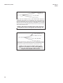
MODEL 5081-P pH/ORP
SECTION 3.0
wIRING
REMOVE BNC ANd TERMiNATE COAXiAL CABLE BEFORE WiRiNG SENSOR TO
TRANSMiTTER. SEE FiGuRE 3-23. ALTERNATiVELY, uSE A BNC AdAPTER (PN
9120531) OR ORdER MOdEL OPTiON -62 (SENSOR WiTH BNC REMOVEd ANd TERMiNATiONS COMPATiBLE WiTH 5081 pH/ORP). iF uSiNG A BNC AdAPTER, THE REd
WiRE iS MV OR pH iN ANd THE BLACK WiRE iS REFERENCE iN. TO PREVENT
SHORT CiRCuiTS TO THE TRANSMiTTER HOuSiNG, iNSuLATE THE BNC BY WRAPPiNG iT WiTH ELECTRiCAL TAPE.
FIGURE 3-2. wire functions for Models 399-02, 399-09, 381pH-30-41,
and 381pHE-31-41 before removing BNC and terminating cable.
iF uSiNG A BNC AdAPTER, THE REd WiRE iS MV OR pH iN ANd THE BLACK WiRE
iS REFERENCE iN. TO PREVENT SHORT CiRCuiTS TO THE TRANSMiTTER HOuSiNG, iNSuLATE THE BNC WiTH BY WRAPPiNG iT WiTH ELECTRiCAL TAPE.
FIGURE 3-3. wire functions for Models 399-02, 399-09,
381pH-30-41, and 381pHE-31-41 after removing BNC and
terminating cable. wire functions for Models 399-09-10-62,
381pH-30-42 and 381pHE-31-42 as received.
20
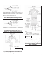
MODEL 5081-P pH/ORP
SECTION 3.0
wIRING
REMOVE BNC ANd TERMiNATE COAXiAL CABLE BEFORE WiRiNG SENSOR TO
TRANSMiTTER. SEE FiGuRE 3-20. ALTERNATiVELY, uSE A BNC AdAPTER (PN
9120531) OR ORdER MOdEL OPTiON -62 (SENSOR WiTH BNC REMOVEd ANd
TERMiNATiONS COMPATiBLE WiTH 5081 pH/ORP). iF uSiNG A BNC AdAPTER,
THE REd WiRE iS MV OR pH iN ANd THE BLACK WiRE iS REFERENCE iN. TO
PREVENT SHORT CiRCuiTS TO THE TRANSMiTTER HOuSiNG, iNSuLATE THE
BNC WiTH BY WRAPPiNG iT WiTH ELECTRiCAL TAPE.
FIGURE 3-6. wire functions for Models 397-50, 397-54, 396-50,
396-54, 396R-50-60, 396R-54-60, 389-02-50, and 389-02-54
before removing BNC and terminating cable.
iF uSiNG A BNC AdAPTER, THE REd WiRE iS MV OR pH iN ANd THE BLACK WiRE
iS REFERENCE iN. TO PREVENT SHORT CiRCuiTS TO THE TRANSMiTTER
HOuSiNG, iNSuLATE THE BNC WiTH BY WRAPPiNG iT WiTH ELECTRiCAL TAPE.
4
FIGURE 3-7. wire functions for Models 397-50, 397-54, 396-50,
396-54, 396R-50-60, 396R-54-60, 389-02-50, and 389-02-54 after
removing BNC and terminating cable. wire functions for
Models 397-54-62, 396-54-62, and 389-02-54-62 as received.
dWG. NO.
405081P19
REV.
A
FIGURE 3-9. wiring diagram for Models 397-50,
397-54, 396-50, 396R-50-60, 396R-54-60, 396-54,
389-02-50, and 389-02-54 after removing BNC
and terminating cable. wiring diagram for
Models 397-54-62, 396-54-62, and 389-02-54-62
as received. wiring through a remote junction
box to the transmitter.
dWG. NO.
405081P12
REV.
A
FIGURE 3-8. wiring diagram for Models 397-50, 397-54, 396-50,
396-54, 389-02-50, and 389-02-54 after removing BNC and terminating cable. wiring diagram for Models 397-54-62, 396-54-62, and
389-02-54-62 as received. wiring directly to the transmitter.
21
MODEL 5081-P pH/ORP
SECTION 3.0
wIRING
FIGURE 3-10. wire functions for Models 396R-50,
396R-54, 396R-54-61, 396P-02-50, 396P-02-54,
396P-02-55, 385+ -04, and 385+ -41-52.
dWG. NO.
405081P24
dWG. NO.
405081P18
REV.
A
FIGURE 3-11. wiring diagram for Models 396R-50,
396R-54, 396R-54-61, 396P-02-50, 396P-02-54,
396P-02-55, 385+ -04, and 385+ -41-52.
wiring directly to the transmitter.
22
REV.
A
FIGURE 3-12. wiring diagram for Models 396R-50,
396R-54, 396R-54-61, 396P-02-50, 396P-02-54,
396P-02-55, 385+ -04, and 385+ -41-52.
wiring through a sensor-mounted junction
box to the transmitter.
MODEL 5081-P pH/ORP
SECTION 3.0
wIRING
FIGURE 3-13. wire functions for Models 396P-01-55, 385+ -03,
381+ -40-55, and 381+ -43-55.
dWG. NO.
405081P17
REV.
A
FIGURE 3-14. wiring diagram for Models 396P-01-55,
385+ -03, 381+ -40-55, and 381+ -43-55.
23
MODEL 5081-P pH/ORP
SECTION 3.0
wIRING
dWG. NO.
405081P20
REV.
A
FIGURE 3-15. wire functions for Model 328A-07.
dWG. NO.
405081P20
REV.
A
FIGURE 3-16. wiring diagram for Models 328A and
382+-02.
dWG. NO.
45081P25
REV.
A
FIGURE 3-17. wiring diagram for Model 385+-02.
24
MODEL 5081-P pH/ORP
SECTION 3.0
wIRING
dWG. NO.
405081P21
REV.
A
FIGURE 3-18. wiring diagram for Model 320HP-10-55.
dWG. NO.
405081P15
REV.
A
FIGURE 3-19 wiring diagram for Model 320HP-10-58.
25
MODEL 5081-P pH/ORP
FIGURE 3-20. Procedure for Removing BNC Connector and Preparing Coaxial Cable
26
SECTION 3.0
wIRING
MODEL 5081-P pH/ORP
SECTION 3.0
wIRING
FIGURE 3-21. Preparation of Raw Connecting Cable (PN 9200273).
27
28
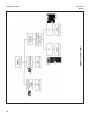
See Flowchart
on page 30
SENSOR FLOw CHART (continued on page 31)
See Flowchart
on page 29
MODEL 5081-P pH/ORP
SECTION 3.0
wIRING
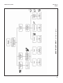
SENSOR FLOw CHART (continued on page 32)
MODEL 5081-P pH/ORP
SECTION 3.0
wIRING
29
SECTION 3.0
wIRING
SENSOR FLOw CHART
MODEL 5081-P pH/ORP
30
MODEL 5081-P pH/ORP
SECTION 4.0
INTRINSICALLy SAFE & ExPLOSION PROOF
SECTION 4.0
INTRINSICALLy SAFE & ExPLOSION PROOF
SUBSTITUTION OF
C O M P O N E N T S M Ay
I M PA I R I N T R I N S I C S A F E T y
PN 23572-00
wA R N I N G :
TO PREvENT IGNITION
C H A N G E B AT T E R I E S I N
A NONHAzARDOUS AREA
O N Ly
IS/I/1/A,B,C & D
NI/I/2/A,B,C & D
T 4 Ta m b = 4 0 ° C
T 3 A Ta m b = 8 0 ° C
yEAR
IRC - INFRARED REMOTE CONTROL
LR 34186
Exia
I N T R I N S I C A L Ly S A F E E Q U I P M E N T
H A z A R D O U S A R E A L O C AT I O N S :
CLASS I, DIv 1, GP A, B, C, D
CLASS I, DIv 2, GP A, B, C, D
T 3 C Ta m b = 4 0 ° C
T 3 Ta m b = 8 0 ° C
1 . 5 v d c A A A B AT T E R I E S
EvEREADy E92/1212
DURACELL MN2400/PC2400
REMOTE CONTROL
B a s e e f a 0 2 AT E x 0 1 9 8
II 1G EExia IIC T4
11 8 0
1 . 5 v d c A A A B AT T E R I E S
EvEREADy E92/1212
DURACELL MN2400/PC2400
R O S E M O U N T A N A Ly T I C A L 9 2 6 0 6 U S A
FIGURE 4-1. Model 5081-P-HT Infrared Remote Control — CSA, FM, & Baseefa/ATEx approvals
SUBSTITUTION OF
C O M P O N E N T S M Ay
I M PA I R I N T R I N S I C S A F E T y
PN 23572-00
wA R N I N G :
TO PREvENT IGNITION
C H A N G E B AT T E R I E S I N
A NONHAzARDOUS AREA
O N Ly
IS/I/1/A,B,C & D
NI/I/2/A,B,C & D
T 4 Ta m b = 4 0 ° C
T 3 A Ta m b = 8 0 ° C
yEAR
IRC - INFRARED REMOTE CONTROL
LR 34186
Exia
I N T R I N S I C A L Ly S A F E E Q U I P M E N T
H A z A R D O U S A R E A L O C AT I O N S :
CLASS I, DIv 1, GP A, B, C, D
CLASS I, DIv 2, GP A, B, C, D
T 3 C Ta m b = 4 0 ° C
T 3 Ta m b = 8 0 ° C
1 . 5 v d c A A A B AT T E R I E S
EvEREADy E92/1212
DURACELL MN2400/PC2400
REMOTE CONTROL
B a s e e f a 0 2 AT E x 0 1 9 8
II 1G EExia IIC T4
11 8 0
1 . 5 v d c A A A B AT T E R I E S
EvEREADy E92/1212
DURACELL MN2400/PC2400
R O S E M O U N T A N A Ly T I C A L 9 2 6 0 6 U S A
FIGURE 4-2. Model 5081-P-FF Infrared Remote Control — CSA, FM, & Baseefa/ATEx approvals
31
MODEL 5081-P pH/ORP
SECTION 4.0
INTRINSICALLy SAFE & ExPLOSION PROOF
FIGURE 4-3. FM Explosion-Proof Installation for Model 5081-P-HT
4.1 INTRINSICALLy SAFE AND ExPLOSION-PROOF INSTALLATIONS FOR MODEL 5081-P-HT
32
SECTION 4.0
INTRINSICALLy SAFE & ExPLOSION PROOF
FIGURE 4-4. FM Intrinsically Safe Label for Model 5081-P-HT
MODEL 5081-P pH/ORP
33
FIGURE 4-5. FM Intrinsically Safe Installation for Model 5081-P-HT (1 of 2)
MODEL 5081-P pH/ORP
34
SECTION 4.0
INTRINSICALLy SAFE & ExPLOSION PROOF
FIGURE 4-5. FM Intrinsically Safe Installation for Model 5081-P-HT (2 of 2)
MODEL 5081-P pH/ORP
SECTION 4.0
INTRINSICALLy SAFE & ExPLOSION PROOF
35
SECTION 4.0
INTRINSICALLy SAFE & ExPLOSION PROOF
FIGURE 4-6. CSA Intrinsically Safe Label for Model 5081-P-HT
MODEL 5081-P pH/ORP
36
FIGURE 4-7. CSA Intrinsically Safe Installation for Model 5081-P-HT (1 of 2)
MODEL 5081-P pH/ORP
SECTION 4.0
INTRINSICALLy SAFE & ExPLOSION PROOF
37
FIGURE 4-7. CSA Intrinsically Safe Installation for Model 5081-P-HT (2 of 2)
MODEL 5081-P pH/ORP
38
SECTION 4.0
INTRINSICALLy SAFE & ExPLOSION PROOF
SECTION 4.0
INTRINSICALLy SAFE & ExPLOSION PROOF
FIGURE 4-8. ATEx Intrinsically Safe Label for Model 5081-P-HT
MODEL 5081-P pH/ORP
39
MODEL 5081-P pH/ORP
SECTION 4.0
INTRINSICALLy SAFE & ExPLOSION PROOF
FIGURE 4-9. FM Explosion-Proof Installation for Model 5081-P-FF
4.2 INTRINSICALLy SAFE AND ExPLOSION-PROOF INSTALLATIONS FOR MODEL 5081-P-FF
40
SECTION 4.0
INTRINSICALLy SAFE & ExPLOSION PROOF
FIGURE 4-10. FM Intrinsically Safe Label for Model 5081-P-FF
MODEL 5081-P pH/ORP
41
FIGURE 4FIGURE 4-11. FM Intrinsically Safe Installation for Model 5081-P-FF (1 of 2)
MODEL 5081-P pH/ORP
42
SECTION 4.0
INTRINSICALLy SAFE & ExPLOSION PROOF
FIGURE 4FIGURE 4-11. FM Intrinsically Safe Installation for Model 5081-P-FF (2 of 2)
MODEL 5081-P pH/ORP
SECTION 4.0
INTRINSICALLy SAFE & ExPLOSION PROOF
43
SECTION 4.0
INTRINSICALLy SAFE & ExPLOSION PROOF
FIGURE 4-12. CSA Intrinsically Safe Label for Model 5081-P-FF
MODEL 5081-P pH/ORP
44
FIGURE 4-13. CSA Intrinsically Safe Installation for Model 5081-P-FF (1 of 2)
MODEL 5081-P pH/ORP
SECTION 4.0
INTRINSICALLy SAFE & ExPLOSION PROOF
45
FIGURE 4-13. CSA Intrinsically Safe Installation for Model 5081-P-FF (2 of 2)
MODEL 5081-P pH/ORP
46
SECTION 4.0
INTRINSICALLy SAFE & ExPLOSION PROOF
SECTION 4.0
INTRINSICALLy SAFE & ExPLOSION PROOF
FIGURE 4-14. ATEx Intrinsically Safe Label for Model 5081-P-FF
MODEL 5081-P pH/ORP
47
48
APPROVED
MATERIAL: AISI 300 SERIES STAINLESS
STEEL .015+/-.005 THICK. MATERIAL TO
BE ANNEALED & PASSIVATED. MAXIMUM
HARDNESS BRINELL 190.
1
FINISH
ANGLES
TOLERANCES
+ 1/2
-
4
1
DIMENSIONS ARE IN INCHES
REMOVE BURRS & SHARP EDGES .020 MAX
MACHINED FILLET RADII .020 MAX
NOMINAL SURFACE FINISH 125
MATERIAL
.XXX
+ .030
+- .010
UNLESS OTHERWISE SPECIFIED
.XX
LTR
PART NO
A
REV
THIS DWG CREATED IN
SOLID EDGE
PROJECT
ENGR APVD J. FLOCK
J. FLOCK
B. JOHNSON
APPROVALS
CHECKED
DRAWN
ITEM
2.56 ±.02
8933
5-6-04
2.180
.120 ±.015
ECO NO
RELEASE DATE
ECO
DATE
5/6/04
5/6/04
5/3/04
SCALE 2:1
B
SIZE
BY
DATE
REV
REV
REV
REV
REV
REV
A
9241503-01
SHEET 1 OF
CHK
2
10-96
A
REV
QTY
Rosemount Analytical,
Uniloc Division
2400 Barranca Pkwy
Irvine, CA 92606
REVISIONS NOT PERMITTED
W/O AGENCY APPROVAL
FM
THIS DOCUMENT IS
CERTIFIED BY
LABEL, I.S. FM
5081-P-FI
DESCRIPTION
DWG NO
Uniloc
TITLE
REVISIONS
DESCRIPTION
BILL OF MATERIAL
FIGURE 4-15. FM Intrinsically Safe Label for Model 5081-P-FI
NO CHANGE WITHOUT FM APPROVAL.
2.
NOTES: UNLESS OTHERWISE SPECIFIED
ARTWORK IS SHEET 2 OF 2.
1.30 ±.02
2X.650 ±.015
3.
.125
9241503-01/A
EXPLOSION PROOF
CLASS I, DIV.1, GRPS. B,C & D
CLASS II, DIV. 1, GRPS. E,F & G
CLASS III, DIV. 1
PER DWG. 1400296
INTRINSICALLY SAFE FOR
CLASS I, II & III, DIV. 1,
GRPS. A,B,C,D,E,F & G
HAZARDOUS AREA WHEN
CONNECTED PER DWG. 1400287
Tamb= 70°C
T4
NON-INCENDIVE
CLASS I, DIV. 2, GRPS. A,B,C & D
DUST IGNITION PROOF
CLASS II AND III, DIV. 1,
GRPS. E, F & G
WARNING: COMPONENT SUBSTITUTION
MAY IMPAIR INTRINSIC SAFETY
OR SUITABILITY FOR DIV. 2.
NEMA 4X ENCLOSURE.
FINISH:SILKSCREEN BLACK EPOXY PAINT (BAKED).
.140
R
Ø .125
ROSEMOUNT ANALYTICAL
MODEL
FM
5081-P-FI-67
4
2X FULL R
4X R .25
This document contains information proprietary to
Rosemount Analytical, and is not to be made available
to those who may compete with Rosemount Analytical.
MODEL 5081-P pH/ORP
SECTION 4.0
INTRINSICALLy SAFE & ExPLOSION PROOF
4.3 INTRINSICALLy SAFE AND ExPLOSION-PROOF INSTALLATIONS FOR MODEL 5081-P-FI
B 9241503-01
A
B
C
D
REV
REV
REV
REV
REV
REV
B
NOTES: UNLESS OTHERWISE SPECIFIED
8
+PH
SENSOR
PREAMP
(NOTE 2)
7
MODEL
5081-P-FI
XMTR
MODEL
5081-P-FI
XMTR
MODEL
5081-P-FI
XMTR
MODEL
5081-P-FI
XMTR
6
5
TO PREVENT IGNITION OF FLAMMABLE OR COMBUSTIBLE ATMOSPHERES,
DISCONNECT POWER BEFORE SERVICING.
SUBSTITUTION OF COMPONENTS MAY IMPAIR INTRINSIC SAFETY OR
SUITABILITY FOR DIVISION 2.
3
4
RELEASE DATE
5-6-04
ECO NO.
8933
IS CLASS I, II, III,
DIVISION 1,
GROUPS A, B, C, D, E, F, G;
NI CLASS I,
DIVISION 2,
GROUPS A,B,C,D;
SUITABLE CLASS II,
DIVISION 2,
GROUPS F & G;
SUITABLE CLASS III,
DIVISION 2
REV
B
FINISH
+ 1/2
DIMENSIONS ARE IN INCHES
ANGLES
TOLERANCES
3
REMOVE BURRS & SHARP EDGES .020 MAX
MACHINED FILLET RADII .020 MAX
NOMINAL SURFACE FINISH 125
+ .030
+ .010
-
MATERIAL
.XX
.XXX
UNLESS OTHERWISE SPECIFIED
ANY FM APPROVED
TERMINATOR
ANY FM APPROVED
INTRINSICALLY SAFE
APPARATUS
ANY FM APPROVED
TERMINATOR
ANY FM APPROVED
INTRINSICALLY SAFE
APPARATUS
ANY FM APPROVED
TERMINATOR
ANY FM APPROVED
INTRINSICALLY SAFE
APPARATUS
ANY FM APPROVED
TERMINATOR
ANY FM APPROVED
INTRINSICALLY SAFE
APPARATUS
HAZARDOUS (CLASSIFIED)LOCATIONS
4
PART NO.
J. FLOCK
ANY FM APPROVED
TERMINATOR
ANY FM APPROVED
TERMINATOR
2
5/6/04
5/6/04
5/3/04
DATE
1
BY
DATE
DESCRIPTION
Uniloc
BILL OF MATERIAL
D
SCALE NONE
SIZE
Rosemount Analytical,
Uniloc Division
2400 Barranca Pkwy
Irvine, CA 92606
1
SHEET 1 OF
2
10-96
B
REV
QTY
ANY FM APPROVED
ASSOCIATED
APPARATUS
ANY FM APPROVED
ASSOCIATED
APPARATUS
ANY FM APPROVED
ASSOCIATED
APPARATUS
1400287
TYPE
CHK
ANY FM APPROVED
ASSOCIATED
APPARATUS
SCHEMATIC, INSTALLATION
5081-P-FI XMTR
FM APPROVALS
TITLE
ANY FM APPROVED
TERMINATOR
THIS DWG CREATED IN
SOLID EDGE
PROJECT
ENGR APVD
CHECKED J. FLOCK
REVISION
DESCRIPTION
NON-HAZARDOUS LOCATIONS
2
ANY FM APPROVED
TERMINATOR
B. JOHNSON
APPROVALS
ECO
DRAWN
ITEM
LTR
FIGURE 4-16. FM Intrinsically Safe Installation for Model 5081-P-FI (1 of 2)
WARNING-
WARNING-
TB14
5
7
10
FM APPROVED PREAMP
THAT MEETS REQUIREMENTS
OF NOTE 1
PREAMP
(NOTE 2)
RECOMMENDED CABLE
4 WIRES SHIELDED
22 AWG. SEE NOTE 1
PH
SENSOR
WITH
TC
+PH
SENSOR
RECOMMENDED CABLE
PN 9200273 (UNPREPPED)
PN 23646-01 PREPPED
10 COND, 2 SHIELDS 24 AWG
SEE NOTE 1
FM APPROVED PREAMP
THAT MEETS REQUIREMENTS
OF NOTE 1
+PH
SENSOR
INFRARED RED
REMOTE CONTROL UNIT
(RMT PN 23572-00)
FOR USE IN
CLASS I AREA ONLY
NOTES ON SHEET 2 OF 2
REVISIONS NOT PERMITTED
W/O AGENCY APPROVAL
FM
THIS DOCUMENT IS
CERTIFIED BY
5
FISCO
FM INTRINSIC SAFETY INSTALLATION
6
5
3
2
7
6
6
8
11
This document contains information proprietary to
Rosemount Analytical, and is not to be made available
to those who may compete with Rosemount Analytical.
4
3
2
1
4
3
2
1
4
3
2
1
5
5
5
7
7
7
7
12
1
4
8
8
8
8
6
6
9
9
9
9
13
14
16 15
13
14
10
10
10
10
11
11
11
12
12
12
16 15
13
14
16 15
13
14
A
B
C
D 1400287
16 15
MODEL 5081-P pH/ORP
SECTION 4.0
INTRINSICALLy SAFE & ExPLOSION PROOF
49
50
A
B
6
8
NOTES: UNLESS OTHERWISE SPECIFIED
7
6
(La/Ra OR Lo/Ro)
5
5
TABLE I
25
5.99
TABLE III
Vmax (Vdc)
17.5
17.5
GROUPS
IIB/
C,D,E,F,G
IIC/
A,B,C,D,E,F,G
MODEL NO.
5081-P-FI
5081-P-FI
4
3
360
380
Imax (mA)
3
2.52
5.32
5
5
10
10
Li (uH)
147 mW
Pt
Ci (nF)
105.64 mA
It
Pmax (W)
13.02 Vdc
Vt
MODEL 5081-P-FI
TB1-1 THRU 12
TABLE II
OUTPUT
PARAMETERS
5081-P-FI FISCO PARAMETERS
SUPPLY / SIGNAL TERMINALS TB 1-15, 16
3.1
12.3
0.96
21.69
C
La
(mH)
D
Ca
(uF)
OUTPUT PARAMETERS
A, B
GAS
GROUPS
4
FIGURE 4-16. FM Intrinsically Safe Installation for Model 5081-P-FI (2 of 2)
THE CAPACITANCE AND INDUCTANCE OF THE LOAD CONNECTED TO THE
SENSOR TERMINALS MUST NOT EXCEED THE VALUES SPECIFIED IN TABLE I
WHERE Ca
Ci (SENSOR) + Ccable;
La
Li (SENSOR) + Lcable.
1. THE MODEL 5081-P-FI TRANSMITTER INCLUDES INTEGRAL PREAMPLIFIER
CIRCUITRY. AN EXTERNAL PREAMPLIFIER MAY BE ALSO USED.
THE OUTPUT PARAMETERS SPECIFIED IN TABLE II ARE VALID FOR EITHER
PREAMPLIFIER.
2. PREAMPLIFIER TYPE 23546-00, 23538-00 OR 23561-00 MAY BE UTILIZED INSTEAD
OF THE MODEL 5081-P-FI TRANSMITTER INTEGRAL PREAMPLIFIER
CIRCUIRTY. A WEATHER RESISTANT ENCLOSURE MUST HOUSE THE TYPE
23546-00 REMOTE PREAMPLIFIER.
3. INSTALLATION SHOULD BE IN ACCORDANCE WITH ANSI/ISA RP12.06
"INSTALLATION OF INTRINSICALLY SAFE SYSTEMS FOR HAZARDOUS
(CLASSIFIED) LOCATIONS" (EXCEPT CHAPTER 5 FOR FISCO INSTALLATIONS) AND
THE NATIONAL ELECTRICAL CODE (ANSI/NFPA 70) SECTIONS 504 AND 505.
4. SENSORS WITHOUT PREAMPS SHALL MEET THE REQUIREMENTS OF SIMPLE APPARATUS AS
DEFINED IN ANSI/ISA RP12.6 AND THE NEC, ANSI/NFPA 70.
THEY CAN NOT GENERATE NOR STORE MORE THAN 1.5V, 0.1A OR A PASSIVE COMPONENT
THAT DOES NOT DISSIPATE MORE THAN 1.3W. SEE TABLES I AND II.
5. DUST-TIGHT CONDUIT SEAL MUST BE USED WHEN INSTALLED IN CLASS II AND
CLASS III ENVIRONMENTS.
6. RESISTANCE BETWEEN INTRINSICALLY SAFE GROUND AND EARTH GROUND MUST BE
LESS THAN 1.0 Ohm.
7. THE ENTITY CONCEPT ALLOWS INTERCONNECTION OF INTRINSICALLY SAFE APPARATUS
WITH ASSOCIATED APPARATUS WHEN THE FOLLOWING IS TRUE:
FIELD DEVICE INPUT
ASSOCIATED APPARATUS OUTPUT
Vmax OR Ui
Voc, Vt OR Uo;
Imax OR Ii
Isc, It OR Io;
Pmax OR Pi
Po;
3Ci+ 3Ccable;
Ca, Ct OR Co
3Li+ 3Lcable.
La, Lt OR Lo; OR Lc/Rc
(La/Ra OR Lo/Ro) AND Li/Ri
8. ASSOCIATED APPARATUS MANUFACTURER'S INSTALLATION DRAWING MUST BE FOLLOWED
WHEN INSTALLING THIS EQUIPMENT.
9. CONTROL EQUIPMENT CONNECTED TO ASSOCIATED APPARATUS MUST NOT USE OR GENERATE
MORE THAN 250 Vrms OR Vdc.
10. THE CONFIGURATION OF ASSOCIATED APPARATUS MUST BE FACTORY MUTUAL RESEARCH APPROVED
UNDER THE ASSOCIATED CONCEPT.
11. NO REVISION TO DRAWING WITHOUT PRIOR FACTORY MUTUAL RESEARCH APPROVAL.
7
2
2
D
DWG NO.
SCALE: NONE
SIZE
TYPE
1
1400287
1
SHEET 2 OF 2
08-94
B
REV
A
B
C
D 1400287
C
D
8
This document contains information proprietary to
Rosemount Analytical, and is not to be made available
to those who may compete with Rosemount Analytical.
MODEL 5081-P pH/ORP
SECTION 4.0
INTRINSICALLy SAFE & ExPLOSION PROOF
R
SA
R
LR34186
ENCLOSURE 4
NO CHANGE WITHOUT CSA APPROVAL.
MATERIAL: AISI 300 SERIES STAINLESS
STEEL .015+/-.005 THICK. MATERIAL TO
BE ANNEALED & PASSIVATED. MAXIMUM
HARDNESS BRINELL 190.
2.
1
NOTES: UNLESS OTHERWISE SPECIFIED
.XXX
.XX
FINISH
ANGLES
TOLERANCES
+ 1/2
-
4
1
DIMENSIONS ARE IN INCHES
REMOVE BURRS & SHARP EDGES .020 MAX
MACHINED FILLET RADII .020 MAX
NOMINAL SURFACE FINISH 125
+ .030
+- .010
A
REV
LTR
ECO
PART NO
THIS DWG CREATED IN
SOLID EDGE
PROJECT
ENGR APVD J. FLOCK
J. FLOCK
B. JOHNSON
APPROVALS
CHECKED
DRAWN
ITEM
DATE
5/6/04
5/6/04
5/3/04
DESCRIPTION
DATE
REV
REV
REV
REV
REV
REV
A
SHEET 1 OF
CHK
2
10-96
A
REV
QTY
Rosemount Analytical,
Uniloc Division
2400 Barranca Pkwy
Irvine, CA 92606
REVISIONS NOT PERMITTED
W/O AGENCY APPROVAL
CSA
9241504-01
DWG NO
SCALE 2:1
B
SIZE
BY
THIS DOCUMENT IS
CERTIFIED BY
LABEL, I.S. CSA
5081-P-FI
Uniloc
TITLE
REVISIONS
DESCRIPTION
BILL OF MATERIAL
FINISH:SILKSCREEN BLACK EPOXY PAINT (BAKED).
UNLESS OTHERWISE SPECIFIED
4
2.180 ±.005
2.56 ±.02
8925
ECO NO
FIGURE 4-17. CSA Intrinsically Safe Label for Model 5081-P-FI
.650 ±.015
1.30 ±.02
ARTWORK IS SHEET 2 OF 2.
.125
9241504-01/A
CLASS I, DIV. 2, GRPS A,B,C & D
SUITABLE FOR
CLASS II, DIV. 2, GRPS E, F & G
Tamb= 70°C
T4
WARNING-EXPLOSION HAZARD-DO NOT
DISCONNECT WHILE CIRCUIT IS LIVE
UNLESS AREA IS KNOWN TO BE NONHAZARDOUS.
WARNING-EXPLOSION HAZARD-SUBSTITUTION OF COMPONENTS MAY IMPAIR
SUITABILITY FOR CLASS I, DIV 2.
CLASS I, GRPS B,C & D
CLASS II, GRPS E, F & G
CLASS III
Tamb = 65°C MAX
Tamb ABOVE 60°C USE 75°C MINIMUM
RATED WIRING
SEAL REQUIRED TO BE INSTALLED
WITHIN 50 mm OF THE ENCLOSURE.
KEEP COVER TIGHT WHILE CIRCUITS
ARE LIVE.
Exia ENTITY
INTRINSICALLY SAFE FOR
CLASS I, GRPS A, B, C & D
CLASS II, GRPS E, F & G
CLASS III
T4 Tamb = 70°C
HAZARDOUS AREA WHEN CONNECTED
PER DWG. 1400288
WARNING: COMPONENT SUBSTITUTION
MAY IMPAIR INTRINSIC SAFETY.
RELEASE DATE
5-6-04
.120 ±.015
MATERIAL
Ø .125
ROSEMOUNT ANALYTICAL
MODEL
5081-P-FI-69
3.
.140 ±.005
2X FULL R
4X R .25
This document contains information proprietary to
Rosemount Analytical, and is not to be made available
to those who may compete with Rosemount Analytical.
MODEL 5081-P pH/ORP
SECTION 4.0
INTRINSICALLy SAFE & ExPLOSION PROOF
B 9241504-01
51
A
B
C
D
REV
REV
REV
REV
REV
REV A
8
PREAMP
(NOTE 3)
7
6
MODEL
5081-P-FI
XMTR
MODEL
5081-P-FI
XMTR
6
MODEL
5081-P-FI
XMTR
MODEL
5081-P-FI
XMTR
5
6
5
TO PREVENT IGNITION OF FLAMMABLE OR COMBUSTIBLE ATMOSPHERES,
DISCONNECT POWER BEFORE SERVICING.
ECO NO.
RELEASE DATE
4
8925
5-6-04
NI CLASS I, DIV 2
GRPS A-D
CLASS II, DIV 2
GRPS E-G
IS CLASS I, GRPS A-D
CLASS II, GRPS E-G
CLASS III
HAZARDOUS AREA
4
A
REV
FINISH
ANGLES
TOLERANCES
+
-
3
DIMENSIONS ARE IN INCHES
REMOVE BURRS & SHARP EDGES .020 MAX
MACHINED FILLET RADII .020 MAX
NOMINAL SURFACE FINISH 125
+ .030
+
- .010
MATERIAL
.XX
.XXX
UNLESS OTHERWISE SPECIFIED
3
REVISION
DESCRIPTION
B. JOHNSON
J. FLOCK
THIS DWG CREATED IN
SOLID EDGE
PROJECT
ENGR APVD
CHECKED J. FLOCK
DRAWN
APPROVALS
2
5/6/04
5/6/04
5-3-04
TITLE
SCALE
SIZE
D
NONE
DWG NO.
TYPE
1400288
1
SHEET 1 OF
SCHEMATIC, INSTALLATION
5081-P-FI XMTR CSA
Uniloc
BILL OF MATERIAL
DATE
Rosemount Analytical,
Uniloc Division
2400 Barranca Pkwy
Irvine, CA 92606
UNSPECIFIED
POWER SUPPLY
17.5 VDC MAX
CSA APPROVED
ASSOCIATED APPARATUS
SUITABLE FOR FISCO
SEE NOTE 8 AND TABLE III
DESCRIPTION
UNSPECIFIED
POWER SUPPLY
17.5 VDC MAX
CSA APPROVED
ASSOCIATED APPARATUS
SUITABLE FOR FISCO
SEE NOTE 8 AND TABLE III
PART NO.
UNSPECIFIED
POWER SUPPLY
17.5 VDC MAX
ITEM
1
BY
CSA APPROVED
ASSOCIATED APPARATUS
SUITABLE FOR FISCO
SEE NOTE 8 AND TABLE III
DATE
UNCLASSIFIED AREA
2
UNSPECIFIED
POWER SUPPLY
17.5 VDC MAX
ECO
CSA APPROVED
ASSOCIATED APPARATUS
SUITABLE FOR FISCO
SEE NOTE 8 AND TABLE III
LTR
FIGURE 4-18. CSA Intrinsically Safe Installation for Model 5081-P-FI (1 of 2)
WARNING-
WARNING-
5
SUBSTITUTION OF COMPONENTS MAY IMPAIR INTRINSIC SAFETY OR
SUITABILITY FOR DIVISION 2.
TB14
5
7
10
CSA APPROVED PREAMP
THAT MEETS REQUIREMENTS
OF NOTE 2
PREAMP
(NOTE 3)
RECOMMENDED CABLE
4 WIRES SHIELDED
22 AWG. SEE NOTE 1
PH
SENSOR
WITH
TC
+PH
SENSOR
RECOMMENDED CABLE
PN 9200273 (UNPREPPED)
PN 23646-01 PREPPED
10 COND, 2 SHIELDS 24 AWG
SEE NOTE 1
CSA APPROVED PREAMP
THAT MEETS REQUIREMENTS
OF NOTE 2
+PH
SENSOR
INFRARED RED
REMOTE CONTROL UNIT
(RMT PN 23572-00)
FOR USE IN
CLASS I AREA ONLY
NOTES ON SHEET 2 OF 2
NOTES: UNLESS OTHERWISE SPECIFICED
REVISIONS NOT PERMITTED
W/O AGENCY APPROVAL
CSA
THIS DOCUMENT IS
CERTIFIED BY
+PH
SENSOR
FISCO
CSA INTRINSIC SAFETY INSTALLATION
7
11
8
10
This document contains information proprietary to
Rosemount Analytical, and is not to be made available
to those who may compete with Rosemount Analytical.
1
2
3
4
5
5
4
3
2
1
3
2
6
6
6
1
7
7
7
7
4
5
4
3
2
1
8
8
8
8
12
13
14
16 15
13
14
16 15
13
9
9
9
9
11
11
11
12
12
12
10
10
10
14
16 15
13
52
14
2
10-96
REV
A
QTY
CHK
A
B
C
D 1400288
16 15
MODEL 5081-P pH/ORP
SECTION 4.0
INTRINSICALLy SAFE & ExPLOSION PROOF
A
B
6
8
NOTES: UNLESS OTHERWISE SPECIFIED
7
5
5081-P-FI
4
17.5
Vmax (Vdc)
380
Imax (mA)
5081-P-FI ENTITY PARAMETERS
SUPPLY / SIGNAL TERMINALS TB 1-15, 16
3
3
5.32
27.8
Ci (nF)
0
Li (mH)
147 mW
Pt
Pmax (W)
13.02 Vdc
105.64 mA
It
MODEL 5081-P-FF
TB1-1 THRU 12
TABLE II
Vt
OUTPUT
PARAMETERS
FIGURE 4-18. CSA Intrinsically Safe Installation for Model 5081-P-FI (2 of 2)
6
1. THE MODEL 5081-A-FI TRANSMITTER INCLUDES INTEGRAL PREAMPLIFIER CIRCUITRY. AN EXTERNAL PREAMPLIFIER
MAY BE ALSO USED. THE OUTPUT PARAMETERS SPECIFIED IN TABLE II ARE VALID FOR EITHER PREAMPLIFIER.
THE CAPACITANCE AND INDUCTANCE OF THE LOAD CONNECTED TO THE SENSOR TERMINALS MUST NOT EXCEED
THE VALUES SPECIFIED IN TABLE I WHERE Ca
Ci (SENSOR) + Ccable;
La
Li (SENSOR) + Lcable.
2. INTRINSICALLY SAFE APPARATUS (MODEL 5081-A-FI, FIELDBUS TERMINATOR AND ANY ADDITIONAL
FIELDBUS DEVICES) AND ASSOCIATED APPARATUS (SAFETY BARRIER) SHALL MEET THE FOLLOWING
REQUIREMENTS: THE VOLTAGE (Vmax) AND CURRENT (Imax) OF THE INTRINSICALLY SAFE APPARATUS
MUST BE EQUAL TO OR GREATER THAN THE VOLTAGE (Voc OR Vt) AND CURRENT (Isc OR It) WHICH
CAN BE DELIVERED BY THE ASSOCIATED APPARATUS (SAFETY BARRIER). IN ADDITION, THE MAXIMUM
UNPROTECTED CAPACITANCE (Ci) AND INDUCTANCE (Li) OF THE INTRINSICALLY SAFE APPARATUS,
INCLUDING INTERCONNECTING WIRING, MUST BE EQUAL OR LESS THAN THE CAPACITANCE (Ca) AND
INDUCTANCE (La) WHICH CAN BE SAFELY CONNECTED TO THE APPARATUS. (REF. TABLE III).
3. PREAMPLIFIER TYPE 23546-00, 23538-00 OR 23561-00 MAY BE UTILIZED INSTEAD OF THE MODEL 5081-A-FI TRANSMITTER
INTEGRAL PREAMPLIFIER CIRCUIRTY. A WEATHER RESISTANT ENCLOSURE MUST HOUSE THE TYPE 23546-00 REMOTE PREAMPLIFIER.
4. INSTALLATION SHOULD BE IN ACCORDANCE WITH ANSI/ISA RP12.06.01 "INSTALLATION OF
INTRINSICALLY SAFE SYSTEMS FOR HAZARDOUS (CLASSIFIED) LOCATIONS" AND THE CANADIAN
ELECTRICAL CODE (CSA C22.1).
5. SENSORS WITHOUT PREAMPS SHALL MEET THE REQUIREMENTS OF SIMPLE APPARATUS AS DEFINED IN ANSI/ISA RP12.6
AND THE CEC (CSA C22.1). THEY CAN NOT GENERATE NOR STORE MORE THAN 1.5V, 0.1A, 25mW, AND 20uJ.
SEE TABLES I AND II.
6. DUST-TIGHT CONDUIT SEAL MUST BE USED WHEN INSTALLED IN CLASS II AND CLASS III ENVIRONMENTS.
MODEL NO.
21.69
D
TABLE III
25
5.99
C
7. RESISTANCE BETWEEN INTRINSICALLY SAFE GROUND AND EARTH GROUND MUST BE LESS THAN 1.0 Ohm.
3.1
12.3
0.96
A, B
8. THE ENTITY CONCEPT ALLOWS INTERCONNECTION OF INTRINSICALLY SAFE APPARATUS
WITH ASSOCIATED APPARATUS WHEN THE FOLLOWING IS TRUE:
FIELD DEVICE INPUT
ASSOCIATED APPARATUS OUTPUT
Vmax OR Ui
Voc, Vt OR Uo;
Isc, It OR Io;
Imax OR Ii
Po;
Pmax OR Pi
Ci+ Ccable;
Ca, Ct OR Co
La, Lt OR Lo
Li+ Lcable.
OUTPUT PARAMETERS
Ca
La
(uF)
(mH)
TABLE I
4
GAS
GROUPS
5
9. ASSOCIATED APPARATUS MANUFACTURER'S INSTALLATION DRAWING MUST BE FOLLOWED
WHEN INSTALLING THIS EQUIPMENT.
10. CONTROL EQUIPMENT CONNECTED TO ASSOCIATED APPARATUS MUST NOT USE OR GENERATE
MORE THAN 250 Vrms OR Vdc.
11. THE ASSOCIATED APPARATUS MUST BE CSA APPROVED.
12. NO REVISION TO DRAWING WITHOUT PRIOR CSA APPROVAL.
7
2
2
D
SIZE
DWG NO.
SCALE: NONE
TYPE
1
1400288
1
SHEET 2 OF 2
A
08-94
REV
A
B
C
D 1400288
C
D
8
This document contains information proprietary to
Rosemount Analytical, and is not to be made available
to those who may compete with Rosemount Analytical.
MODEL 5081-P pH/ORP
SECTION 4.0
INTRINSICALLy SAFE & ExPLOSION PROOF
53
54
II 1 G
NO CHANGE WITHOUT BASEEFA APPROVAL.
MATERIAL: AISI 300 SERIES STAINLESS
STEEL .015+/-.005 THICK. MATERIAL TO
BE ANNEALED & PASSIVATED. MAXIMUM
1
NOTES: UNLESS OTHERWISE SPECIFIED
RELEASE DATE
FINISH
ANGLES
TOLERANCES
+ 1/2
-
4
1
DIMENSIONS ARE IN INCHES
REMOVE BURRS & SHARP EDGES .020 MAX
MACHINED FILLET RADII .020 MAX
NOMINAL SURFACE FINISH 125
+ .030
+- .010
MATERIAL
.XXX
.XX
2.56 ±.02
8925
ECO NO
A
REV
LTR
ECO
PART NO
J. FLOCK
THIS DWG CREATED IN
SOLID EDGE
PROJECT
ENGR APVD
J. FLOCK
B. JOHNSON
APPROVALS
CHECKED
DRAWN
ITEM
5/6/04
5/6/04
5/3/04
DATE
DESCRIPTION
DATE
REV
REV
REV
REV
REV
REV
A
SHEET 1 OF
CHK
2
10-96
A
REV
QTY
Rosemount Analytical,
Uniloc Division
2400 Barranca Pkwy
Irvine, CA 92606
Baseefa Certified Product
No modifications permitted
without the approval of
the Authorized Person
Related Drawing
REVISIONS NOT PERMITTED
W/O AGENCY APPROVAL
Baseefa
9241502-01
DWG NO
SCALE 2:1
B
SIZE
BY
THIS DOCUMENT IS
CERTIFIED BY
LABEL, I.S. BAS/ATEX
5081-P-FI
Uniloc
TITLE
REVISIONS
DESCRIPTION
BILL OF MATERIAL
FINISH:SILKSCREEN BLACK EPOXY PAINT (BAKED).
UNLESS OTHERWISE SPECIFIED
4
2.180 ±.005
.120 ±.015
5-6-04
FIGURE 4.19. ATEx Intrinsically Safe Label for Model 5081-P-FI
.650 ±.015
1.30 ±.02
2.
.125
9241502-01/A
SIGNAL INPUT
Uo = 13.1 VDC
Io = 173 mA
Po = 231 mW
Ci= 0.010 à F
Li= 0 à H
FISCO SUPPLY
Ui = 17.5 VDC
Ii = 380 mA
Pi = 5.32 W
Ci= 0 à F
Li= 0 àH
Baseefa02ATEX1284
EEx ia IIC T4
Tamb = -20°C TO +65°C
MODEL 5081-P-FI-73
1180
ARTWORK IS SHEET 2 OF 2.
HARDNESS BRINELL 190.
R
Ø .125
ROSEMOUNT ANALYTICAL
3.
2X FULL R
.140 ±.005
4X R .25
This document contains information proprietary to
Rosemount Analytical, and is not to be made available
to those who may compete with Rosemount Analytical.
MODEL 5081-P pH/ORP
SECTION 4.0
INTRINSICALLy SAFE & ExPLOSION PROOF
B 9241502-01
MODEL 5081-P pH/ORP
SECTION 5.0
OPERATION wITH REMOTE CONTROLLER
SECTION 5.0
OPERATION wITH INFRARED REMOTE CONTROLLER
5.1
5.2
5.3
5.4
5.5
5.6
5.7
5.8
Overview
Displays
Infrared Remote Controller (IRC) - Key Functions
Menu Tree - pH
Diagnostic Messages - pH
Menu Tree - ORP
Diagnostic Messages - ORP
Security
5.1 OvERvIEw
This section covers basic transmitter operation and software functionality. For detailed descriptions of the function blocks common to all Fieldbus devices, refer to Fisher-Rosemount Fieldbus FOuNdATiON Function Blocks
manual, publication number 00809-4783.
Figure 5-1 illustrates how the pH/ORP signal is channelled through the transmitter to the control room and the
FOuNdATiON Fieldbus configuration device.
FIGURE 5-1. Functional Block Diagram for the Model 5081-P pH/ORP
Transmitter with FOUNDATION Fieldbus.
55
MODEL 5081-P pH/ORP
SECTION 5.0
OPERATION wITH REMOTE CONTROLLER
5.1.1 Software Functionality. The Model 5081-P pH/ORP software is designed to permit remote testing and
configuration of the transmitter using the Fisher-Rosemount deltaV Fieldbus Configuration Tool, or other FOuNdATiON fieldbus compliant host.
5.1.2 Transducer Block. The transducer block contains the actual measurement data. it includes information
about sensor type, engineering units, reranging, damping, temperature compensation, calibration, and diagnostics.
5.1.3 Resource Block. The resource Block contains physical device information, including available memory,
manufacturer identification, type of device, and features.
5.1.4 FOUNDATION fieldbus Function Blocks. The Model 5081-P pH/ORP includes three Analog input (Ai)
function blocks and one input Selector (iSEL) function block as part of its standard offering.
Analog Input. The Analog input (Ai) block processes the measurement and makes it available to other function blocks. it also allows filtering, alarming, and engineering unit change.
Charaterizer (optional). The characterizer block changes the characteristic of the input signal. Common
uses of the characterizer block include converting temperature to density or humidity, and converting millivolts to temperature for an iR sensor.
5.2 DISPLAyS
Figure 5-2 shows the process display screen, and Figure 5-3 shows the program display screen.
pH or ORP (ORP in mV)
Temperature in °C or °F
FIGURE 5-2. Process Display Screen
The process display screen appears during normal operation.
FIGURE 5-3. Program Display Screen
The program display screen appears when calibrating, programming, or reading diagnostic messages.
56
MODEL 5081-P pH/ORP
SECTION 5.0
OPERATION wITH REMOTE CONTROLLER
5.3 INFRARED REMOTE CONTROLLER (IRC) - KEy FUNCTIONS
The infrared remote controller is used to calibrate and program the transmitter and to read diagnostic messages.
See Figure 5-4 for a description of the function of the keys.
RESET - Press to end the current operation and return to the process display.
Changes will NOT be saved. RESET
does not return the transmitter to factory
default settings.
Editing Keys - use the editing keys to
change the value of a flashing display.
The left and right arrow keys move the
cursor one digit at a time across a number. The up and down arrow keys
increase or decrease the value of the
selected digit. The up and down arrow
keys also scroll the display through the
items in a list.
CAL - Press to access the calibrate
menu.*
PROG - Press to access the program
menu.*
HOLD - Press to access the prompt
that turns on or off the Hold function.
HOLd puts the transmitter in hold mode
and sets the output to a pre-programmed value. Press RESET to exit
hold mode.
ENTER - Press to advance from a submenu to the first prompt under the submenu. Pressing ENTER also stores the
selected item or value in memory and
advances to the next prompt.
NExT - Press to advance to the next
sub-menu.
ExIT - Press to end the current operation. The transmitter returns to the first
prompt in the present sub-menu.
Changes will NOT be saved.
DIAG - Press to view diagnostic messages.*
* Pressing CAL, PROG, or DIAG causes
the program screen to appear with the
selected menu (CALIBRATE, PROGRAM,
OR DIAGNOSE) showing. See Figure 5-3.
The first sub-menu (or the first diagnostic
message) also appears. Figure 5-5 shows
the complete menu tree.
FIGURE 5-4. Infrared Remote Controller.
Hold the iRC within 6 feet of the transmitter, and not more than 15 degrees from horizontal to the display window.
57
MODEL 5081-P pH/ORP
SECTION 5.0
OPERATION wITH REMOTE CONTROLLER
5.4 MENU TREE - pH
The Model 5081-P pH transmitter has three menus: CALiBRATE, PROGRAM, and diAGNOSE. under the Calibrate and
Program menus are several sub-menus. For example, under CALiBRATE, the sub-menus are CALIbrAtE, Std (standard), and tEMP AdJ (temperature adjust). under each sub-menu are prompts. For example, under Std, the prompts
are Std xx.xx and slope xx.xx. The diAGNOSE menu lets the user view diagnostic messages. Figure 5-5 shows the
complete menu tree for Model 5081-P-HT. Figure 5-6 shows the complete menu tree for Model 5081-P-FF.
5.5 DIAGNOSTIC MESSAGES - pH
Whenever a warning or fault limit has been exceeded, the transmitter displays diagnostic messages to aid in troubleshooting. diagnostic messages appear in the same area as the temperature/output readings in the process display
screen (see Figure 5-2). The display alternates between the regular display and the diagnostic message. Figure 5-5
shows the diagnostic fault messages for pH. Figure 5-5 shows the diagnostic fault messages for pH for Model 5081-P-HT.
Figure 5-6 shows the diagnostic fault messages for pH for Model 5081-P-FF. if more than one warning or fault message
has been generated, the messages appear alternately.
See Section 11.0, Troubleshooting, for the meanings of the fault and warning messages.
MENU
Sub-menu
PROMPT
diag Message
FIGURE 5-5. pH Menu Tree for Model 5081-P-HT
58
MODEL 5081-P pH/ORP
SECTION 5.0
OPERATION wITH REMOTE CONTROLLER
PROGRAM
CALIBRATE
CALIbrAtE
Std
tEMP AdJ
CAL bF1
Std 7.00
tEMP 25.0
bF 1
SLOPE 59.01
InPut 58.9
DIAGNOSE
SLOPE
OFFSt
GIMP 1000
rIMP 10
5081-P-FF
SoFt
HArd
FAULtS
nonE
bF1 4.01
CAL bF2
bF 2
bF2 10.01
tEMP
dISPLAy
bUFFEr
rOFFSt 060
tAutO On
tYPE PH
bAutO On
tCOEF 00.00
diAG OFF
tMAn 25.0
dIAGnOStIC
ISOPOtntAL LinE FrEq
tEMP C
buFFEr Std
iSO 07.00
iMPtC ON
OutPut Cur
StAbiLiSE
Snr 07.00
GFH 1500
COdE 000
tiME 10
GWH 1000
PAMP=trAnS
dEFAULt
FActOrY
LinE 60
NO
YES
deLtA 00.02
GWL 020
MENU
GFL 010
CAL 000
Sub-menu
rEF LO
rFH 140
PROMPT
rWH 040
diag Message
rWL 000
rFL 000
FIGURE 5-6. pH Menu Tree for Model 5081-P-FF
59
MODEL 5081-P pH/ORP
SECTION 5.0
OPERATION wITH REMOTE CONTROLLER
5.6 MENU TREE - ORP
The Model 5081-P ORP transmitter has three menus: CALiBRATE, PROGRAM, and diAGNOSE. under the Calibrate
and Program menus are several sub-menus. For example, under CALiBRATE, the sub-menus are Std (standard) and
tEMP AdJ (temperature adjust). under each sub-menu are prompts. For example, the Std sub-menu contains the single
prompt Std. Other sub-menus may contain more than one prompt. Figure 5-7 shows the complete menu tree for Model
5081-P-HT. Figure 5-8 shows the complete menu tree for Model 5081-P-FF.
5.7 DIAGNOSTIC MESSAGES - ORP
Whenever a warning or fault limit has been exceeded, the transmitter displays diagnostic messages to aid in troubleshooting. diagnostic messages appear in the same area as the temperature/output readings in the process display
(Figure 5-2). The display alternates between the regular display and the diagnostic message. Figure 5-7 shows the diagnostic fault messages for ORP for Model 5081-P-HT. Figure 5-8 shows the diagnostic fault messages for ORP for Model
5081-P-FF. if more than one warning or fault message has been generated, the messages appear alternately.
See Section 11.0, Troubleshooting, for the meanings of the fault and warning messages.
1400
PROGRAM
CALIBRATE
Std
tEMP ADj
Std 1000
tEMP 25.0
mV
DIAGNOSE
OFFSt 120
rIMP 10
5081-P-Ht
SoFt 00.02
HArd 01
FAULtS
nonE
dIAGnOStIC
dISPLAy
HArt
LinE FrEq
4 MA -1400
rOFFSt 060
tYPE ORP
AddrESS 00
LinE 60
20MA 1400
diAG OFF
tEMP C
PrEAMb 02
HoLd 21.00
iMPtC OFF
OutPut Cur
burSt OFF
FAuLt 22.00
rEF LO
COdE 000
dPn 0.00
rFH 140
tESt 12.00
rWH 040
OutPut
PAMP=trAnS
dEFAULt
FActOrY
nO
id
YES
0
MENU
Sub-menu
rWL 000
rFL 000
PROMPT
diag Message
FIGURE 5-7. ORP Menu Tree for Model 5081-P-HT
60
MODEL 5081-P pH/ORP
SECTION 5.0
OPERATION wITH REMOTE CONTROLLER
1400
mV
PROGRAM
CALIBRATE
Std
tEMP ADj
Std 1000
tEMP 25.0
DIAGNOSE
OFFSt 120
rIMP 10
5081-P-FF
SoFt 00.02
HArd 01
FAULtS
nonE
dIAGnOStIC
dISPLAy
LinE FrEq
rOFFSt 060
tYPE ORP
LinE 60
diAG OFF
tEMP C
iMPtC OFF
OutPut Cur
rEF LO
COdE 000
dEFAULt
PAMP=trAnS
FActOrY
nO
YES
rFH 140
MENU
Sub-menu
rWH 040
PROMPT
rWL 000
rFL 000
diag Message
FIGURE 5-8. ORP Menu Tree for Model 5081-P-FF
61
MODEL 5081-P pH/ORP
SECTION 5.0
OPERATION wITH REMOTE CONTROLLER
5.8 SECURITy
5.8.1 General. use the programmable security code to protect program and calibration
settings from accidentally being changed. The transmitter is shipped with the security feature disabled. To program a security code, refer to Section 8.6, display units.
5.8.2 Entering the Security Code.
PROGRAM
Id
EXiT
000
ENTER
1. if calibration and program settings are protected with a security code, pressing PROG
or CAL on the infrared remote controller causes the Id screen to appear.
2.
use the editing keys to enter the security code. Press ENTER .
3. if the security code is correct, the first sub-menu appears. if the security code is incorrect, the process display reappears.
5.8.3 Retrieving a Lost Security Code.
1. if the security code has been forgotten, enter 555 at the Id prompt and press ENTER .
The transmitter will display the present code.
2. Press EXiT to return to the process display.
3. Press PROG or CAL . The Id screen appears.
4. use the editing keys to enter the security code just shown; then press ENTER .
5. The first sub-menu under the selected menu will appear.
62
MODEL 5081-P pH/ORP
SECTION 6.0
OPERATION wITH MODEL 375
SECTION 6.0
OPERATION wITH MODEL 375
6.1
Note on Model 375 or 475 Communicator
The Model 375 or 475 Communicator is a product of Emerson Process Management, Rosemount inc. This section contains selected information on using the Model 375 or 475 with the Rosemount Analytical Model 5081-P-HT
Transmitter. For complete information on the Model 375 or 475 Communicator, see the Model 375 or 475 instruction manual. For technical support on the Model 375 or 475 Communicator, call Emerson Process Management
at (800) 999-9307 within the united States. Support is available worldwide on the internet at http://rosemount.com.
6.2
Connecting the Communicator
CAUTION
Figure 6-1 shows how the Model 475 or 375 Communicator connects to
the output lines from the Model 5081-P-HT Transmitter.
For intrinsically safe CSA and FM
wiring connections, see the Model
375 instruction manual.
4-20 mA + digital
250
ohm
Model 5081-P
pH/ORP
Transmitter
Control System
Model 375
or 475
Communicator
(“Configurator”)
Bridge
Computer
FIGURE 6-1. Connecting the HART Communicator
63
MODEL 5081-P pH/ORP
SECTION 6.0
OPERATION wITH MODEL 375
6.3
Operation
6.3.1
Off-line and On-line Operation
The Model 375 Communicator features off-line and on-line communications. On-line means the communicator is
connected to the transmitter in the usual fashion. While the communicator is on line, the operator can view measurement data, change program settings, and read diagnostic messages. Off-line means the communicator is not
connected to the transmitter. When the communicator is off line, the operator can still program settings into the
communicator. Later, after the communicator has been connected to a transmitter, the operator can transfer the
programmed settings to the transmitter. Off-line operation permits settings common to several transmitters to be
easily stored in all of them.
6.3.2
Making HART related settings from the keypad
Calibrate
Program
Output
Measurement
Security
Hold
1. Press MENu. The main menu screen appears. Choose Program.
Display
Temp
2. Choose >>.
>>
HART
3. Choose HART.
>>
DevID
PollAddrs
Burst
Preamble
6.3.3
4. To display the device id, choose DevID. To change the polling address,
choose PollAddrs. To make burst mode settings, choose Burst. To
change the preamble count, choose Preamble.
Menu Tree
The menu tree for the Model 375 HART communicator is on the following page. The menu tree for the Model 375
FOuNdATiON Fieldbus communicator is on page 69.
64
MODEL 5081-P pH/ORP
SECTION 6.0
OPERATION wITH MODEL 375
-------------------------------------------------------------------------------5081-P-HT 375 Menu Tree
-------------------------------------------------------------------------------device setup
Process variables
View Fld dev Vars
Oxygen *
Temp
Snsr Cur
pH #
pH mV #
Gi #
Temp Res
View PV-Analog 1
PV is Oxygen *
PV
PV % rnge
PV AO
View SV
SV is Temp **
SV
View TV
TV is Snsr Cur ***
TV
View 4V
4V is Temp Res ****
4V
View Status
diag/Service
Test device
Loop test
View Status
Master Reset
Fault History
Hold Mode
Calibration
Zero Main Sensor
Air Calibration
in-process Cal
dual Range Cal #####
Adjust Temperature
pH 2-Pt Cal #
pH Auto Cal #
Standardize pH #
d/A trim
FIGURE 6-2. 5081-P-HT HART/Model 375 Menu Tree
65
MODEL 5081-P pH/ORP
diagnostic Vars
Oxygen
Snsr Cur
Sensitivity
Zero Current
pH Value #
pH mV #
pH Slope #
pH Zero Offset #
Gi #
Temp
Temp Res
Noise rejection
Basic setup
Tag
PV Range Values
PV LRV
PV uRV
PV
PV % rnge
device information
distributor
Model
dev id
Tag
date
Write protect
Snsr text
descriptor
Message
Revision #'s
universal rev
Fld dev rev
Software rev
Hardware rev
detailed setup
Sensors
Oxygen *
Oxygen unit [ppm, ppb, %sat, mmHg, inHg, atm, kPa, mbar, bar] *, *****
Oxygen Sensor [AdO, TRdO, SSdO1, SSdO2] ##
Salinity ###
Pressure unit [mmHg, inHg, atm, kPa, mbar, bar] ##
use process pressure for %saturation? [No, Yes] ###
Process pressure (Note: Valid only when process pressure is enabled)
Air cal pressure ## (read only)
input filter
Sensor SST
Sensor SSS
dual Range Cal [disable, Enable] ####
FIGURE 6-2. 5081-P-HT HART/Model 375 Menu Tree
66
SECTION 6.0
OPERATION wITH MODEL 375
MODEL 5081-P pH/ORP
SECTION 6.0
OPERATION wITH MODEL 375
pH #
pH Value
pH Comp [Auto, Manual]
Manual pH
Preamp loc [Sensor, Xmtr]
Autocal [Manual, Standard, diN 19267, ingold, Merck]
pH Slope
pH SST
pH SSS
pH Zero Offset Limit
pH diagnostics
diagnostics [Off, On]
GFH
GFL
imped Comp [Off, On]
Temperature
Temp Comp [Auto, Manual]
Man. Temp
Temp unit [ºC, ºF]
Temp Snsr
Signal condition
LRV
uRV
AO damp
% rnge
Xfer fnctn
AO lo end point
AO hi end pt
Output condition
Analog output
AO
AO Alrm typ
Fixed
Fault mode [Fixed, Live]
Fault
Loop test
d/A trim
HART output
PV is Oxygen *
SV is Temp **
TV is Snsr Cur ***
4V is pH ****
Poll addr
Burst option [PV, %range/current, Process vars/crnt]
Burst mode [Off, On]
Num req preams
Num resp preams
FIGURE 6-2. 5081-P-HT HART/Model 375 Menu Tree
67
MODEL 5081-P pH/ORP
SECTION 6.0
OPERATION wITH MODEL 375
device information
distributor
Model
dev id
Tag
date
Write protect
Snsr text
descriptor
Message
Revision #'s
universal rev
Fld dev rev
Software rev
Hardware rev
Local display
AO LOi units [mA, %]
LOi cfg code
LOi cal code
Noise rejection
Load default Conf.
Review
Sensors
Outputs
device information
PV
PV AO
PV LRV
PV uRV
-------------------------------------------------------------------------------Notes:
*
Can be Oxygen, Free Cl, Ozone, Ttl Cl, or Chlrmn
**
Can be *, Temp, pH, Gi
***
Can be *, Snsr Cur, Temp, pH, Gi
**** Can be *, Snsr Cur, Temp, pH, Gi, Temp Res, Not used
***** units for Ozone can be ppm or ppb. For any of the chlorines, unit is
always ppm.
#
Valid when PV = Free Cl
##
Valid when PV = Oxygen
###
Valid when PV = Oxygen and unit = %sat
#### Valid when PV = Free Cl, Ttl Cl, or Chlrmn
##### Valid when dual Range Cal = Enable
FIGURE 6-2. 5081-P-HT HART/Model 375 Menu Tree
68
MODEL 5081-P pH/ORP
SECTION 7.0
CALIBRATION OF pH MEASUREMENTS
SECTION 7.0
CALIBRATION OF pH MEASUREMENTS
7.1
7.2
7.3
7.4
7.5
7.6
7.7
General
Entering and Leaving the Calibrate Menu
Using the Hold Function
Temperature Calibration
Auto Calibration
Manual Calibration
Making the Transmitter Reading Match a
Second pH Meter (Standardization)
7.1 GENERAL
The Calibrate menu allows the user to calibrate the pH and temperature response of the sensor.
The transmitter does a two-point pH calibration. Both manual and auto calibration are available. in auto calibration the
transmitter automatically stores temperature-corrected calibration data once readings have met programmed stability limits. in manual calibration the user enters buffer values and judges when readings are stable. The transmitter reading can
also be made to match the reading of a second pH meter.
Temperature calibration is a one-point standardization against a reference thermometer.
Prompts guide the user through the calibration procedures.
7.2. ENTERING AND LEAvING THE CALIBRATE MENU
Press CAL on the infrared remote controller (iRC) to enter the Calibrate menu. To store new settings in memory, press
ENTER . To leave the Calibrate menu without storing new values, press EXiT . Pressing EXiT with a prompt showing
returns the display to the first prompt in the sub-menu. Pressing EXiT a second time returns the transmitter to the process
display.
if program settings are protected with a security code, pressing PROG or CAL will cause the Id screen to appear. Key
in the security code and press ENTER . The first sub-menu will appear. For more information, see Section 5.8, Security.
A transmitter adjacent to the one being calibrated may pick up signals from the iRC. To avoid accidentally changing settings, use a different security code for each nearby transmitter. See Section 5.8, Security, and Section 8.5, display units,
for details.
7.3 USING THE HOLD FUNCTION
during calibration, the sensor may be exposed to solutions having pH outside the normal range of the process. To prevent
false alarms and possible undesired operation of chemical dosing pumps, place the transmitter in hold during calibration.
Activating hold keeps the transmitter output at the last value or sends the output to a previously determined value.
After calibration, reinstall the sensor in the process stream. Wait until readings have stabilized before deactivating Hold.
To activate or deactivate Hold, do the following:
1. Press HOLd on the iRC.
2. The HoLd prompt appears in the display. Press or to toggle the Hold function between On and OFF.
3. Press ENTER to save.
69
MODEL 5081-P pH/ORP
SECTION 7.0
CALIBRATION OF pH MEASUREMENTS
7.4 TEMPERATURE CALIBRATION
7.4.1 Purpose
1. As discussed in Section 13.6, Glass Electrode Slope, measuring temperature is an important part of measuring pH. The accuracy of a new sensor
and transmitter loop is about ±1°C, which is adequate for most applications.
A new sensor seldom requires temperature calibration.
2. Calibrate the sensor/transmitter loop if . . .
a. ±1°C accuracy is NOT acceptable, or
b. the temperature measurement is suspected of being in error.
NOTE
A transmitter adjacent to the one being calibrated may pick up
signals from the iRC. To avoid accidentally changing settings,
use a different security code for each nearby transmitter. See
Section 5.8, Security.
7.4.2 Procedure
1. Place the pH sensor and a calibrated reference thermometer in an insulated
container of water at ambient temperature. Be sure the temperature element in the sensor is completely submerged by keeping the sensor tip at
least three inches below the water level. do not let the weight of the sensor
rest on the glass bulb. Stir continuously. Allow at least 20 minutes for the
standard thermometer, sensor, and water to reach constant temperature.
2. Enter the CALiBRATE menu by pressing CAL on the iRC. The CALIbrAtE
sub-menu appears (pictured above left).
CALiBRATE
tEMP AdJ
EXiT
NEXT
ENTER
4. Press ENTER to display the temperature editing prompt.
CALiBRATE
tEMP
EXiT
3. At the CALIbrAtE sub-menu, press NEXT twice. The tEMP AdJ sub-menu
appears.
025.0
ENTER
5. Compare the temperature displayed by the transmitter with the temperature
measured with the reference thermometer. if the readings are different, use
the editing keys to change the flashing display to the value determined with
the reference thermometer. The reading cannot be changed by more than
15°C.
6. Press ENTER . The value will be saved, and the display will return to the
tEMP AdJ sub-menu.
7. To leave the CALiBRATE menu, press EXiT .
8. Check linearity by measuring the temperature of water 10 to 15°C cooler
and 10 to 15°C warmer than the water used for calibration. Because of the
time required for the temperature element in the sensor to reach constant
temperature, a well-insulated container or, better, a constant temperature
bath is required for this step.
70
MODEL 5081-P pH/ORP
SECTION 7.0
CALIBRATION OF pH MEASUREMENTS
7.5 AUTO CALIBRATION
7.5.1 Purpose
1.
2.
3.
New sensors must be calibrated before use. Regular recalibration is also necessary.
The use of auto calibration instead of manual calibration is strongly recommended. Auto calibration avoids common pitfalls and reduces errors.
For more information about calibration in pH measurements and the use of buffers, refer to Section 8.7, Buffers and
Calibration.
7.5.2 what Happens During Auto Calibration?
1.
2.
The transmitter displays prompts that guide the user through a two-point buffer calibration.
The transmitter recognizes the buffers and uses the temperature-corrected pH value in the calibration. The transmitter also measures noise and drift and does not accept calibration data until readings are stable. Stability limits
are user-programmable. See Section 8.7, Buffer Calibration Parameters.
7.5.3 Use of Calibration Standards (buffers)
1.
A pH measurement is only as good as the calibration, and the calibration is only as good as the buffers used. A careful buffer calibration is the first step in making an accurate pH measurement.
2. Calibrate with buffers having pH values that bracket the pH of the process. For example, if the pH is between 8 and
9, calibrate with pH 7 and 10 buffers. Commercial buffers for intermediate range pH are readily available. Buffers
outside the range pH 3.0 to pH 10.0 may not be readily available and must be prepared by the user. Tables 7-2 and
7-3 in Section 7.6, Buffer Calibration Parameters, list the buffers that the transmitter recognizes.
3. Allow time for the sensor and buffers to reach the same temperature. if the sensor was just removed from a process
having a temperature more than 10°C different from the buffer, allow at least 20 minutes.
4. For best results, calibrate with buffers having the same temperature as the process. if the buffer and process temperature differ by more than about 15°C an error as great as 0.1pH may result.
5. Be careful using buffers at high temperatures. Protect the solution from evaporation. Evaporation changes the concentration of the buffer and its pH. Be sure the pH of the buffer is defined at high temperatures. Finally, no matter
what the temperature is, allow the entire measurement cell, sensor and solution, to reach constant temperature
before calibrating.
6. The pH of a buffer changes with temperature. Equations relating pH to temperature for common buffers have been
programmed into the Model 5081-P pH transmitter. during auto calibration, the transmitter calculates the correct
buffer value and uses it in the calibration.
7. Buffers have limited shelf lives. do not use a buffer if the expiration date has passed. Store buffers at controlled room
temperature.
8. do not return used buffer to the stock bottle. discard it.
9. Protect buffers from excessive exposure to air. Atmospheric carbon dioxide lowers the pH of alkaline buffers. Other
trace gases commonly found in industrial environments, for example, ammonia and hydrogen chloride, also affect
the pH of buffers. Molds, from airborne spores, grow readily in neutral and slightly acidic buffers. Mold growth can
substantially alter the pH of a buffer.
10. Rinse the sensor with deionized water before placing it in a buffer. Remove excess water from the sensor by gently
daubing it with a clean tissue. do not wipe the sensor. Wiping may generate a static charge, leading to noisy readings. The static charge may take hours to dissipate. A few drops of deionized water carried with the sensor into the
buffer will not appreciably alter the pH.
71
MODEL 5081-P pH/ORP
SECTION 7.0
CALIBRATION OF pH MEASUREMENTS
NOTE
A transmitter adjacent to the one being calibrated may pick up signals from
the iRC. To avoid accidentally changing settings, use a different security code
for each nearby transmitter. See Section 5.8, Security.
NOTE
during calibration, the sensor may be exposed to solutions having pH outside
the normal range of the process. To prevent false alarms and possible undesired operation of chemical dosing pumps, place the analyzer in hold during
calibration. See Section 7.3, using the Hold Function, for details.
7.5.4 Procedure
1.
Verify that auto calibration is activated. identify the buffers being used and set the stability limits.
2.
Enter the CALiBRATE menu by pressing CAL on the iRC. The CALIbrAtE sub-menu appears (pictured above left).
3.
At the CALIbrAtE sub-menu, press ENTER . The CAL bF1 prompt appears.
4.
Rinse the sensor and place it in the first buffer. Be sure the glass bulb and the temperature element
are completely submerged. Keep the sensor tip at least three inches below the liquid level. do not
let the weight of the sensor rest on the glass bulb. Swirl the sensor to dislodge trapped bubbles. The
main display will show the measured pH based on the previous calibration.
5.
Press ENTER . bF1 flashes until the measured pH meets the programmed stability limits. if the pH
reading is not stable after 20 minutes, the transmitter automatically leaves the CALiBRATE menu
and returns to the process mode. if this happens, consult Section 12.5.4, Troubleshooting, for assistance. Once the reading is stable, the display changes to look like the figure at the left. The flashing number is the nominal pH, that is, the pH of the buffer at 25°C. if the flashing number does not
match the nominal pH, press or until the correct pH appears. Press ENTER to save the first
calibration point.
6.
The CAL bF2 prompt appears.
7.
At the CAL bF2 prompt, remove the sensor from the first buffer. Rinse the sensor and place it in the
second buffer. Be sure the glass bulb and the temperature element are completely submerged. Keep
the sensor tip at least three inches below the liquid level. do not let the weight of the sensor rest on the
glass bulb. Swirl the sensor to dislodge trapped bubbles. The main display will show the measured pH
of the buffer based on the previous calibration.
8.
Press ENTER . bF2 flashes until the pH reading is stable. if the pH reading is not stable after 20
minutes, the transmitter automatically leaves the CALiBRATE menu and returns to process mode.
if this happens, consult Section 12.5.4, Troubleshooting, for assistance. Once the reading is stable,
the display changes to look like the figure at the left. The flashing number is the nominal pH, that is,
the pH of the buffer at 25°C. if the flashing number does not match the nominal pH, press or
until the correct pH appears. Press ENTER to save the second calibration point.
9.
The calibration is complete, but the transmitter remains in the CALIbrAtE sub-menu for two minutes after ENTER is pressed.
CALiBRATE
CAL bF 1
EXiT
NEXT
ENTER
CALiBRATE
bF 1
EXiT
4.00
ENTER
CALiBRATE
CAL bF 2
EXiT
ENTER
CALiBRATE
bF 2
EXiT
10.00
ENTER
10. Remove the sensor from the buffer and return it to the process. if the transmitter was in hold during
calibration, wait until readings have stabilized before taking the transmitter out of hold. See Section
6.3, using the Hold Function.
11. The transmitter uses the calibration data to calculate a new slope. Refer to Section 12.7, Buffers
and Calibration, for more details. if the slope is unacceptable, the calibration will not be updated,
and the transmitter will display a SLOPE Err HI or SLOPE Err LO error message. Refer to Section
12.5.3, Troubleshooting, for assistance.
12. To leave the CALiBRATE menu, press EXiT .
13. For quality control and troubleshooting, it is helpful to know the electrode slope. To display the slope,
press CAL on the iRC. The CALIbrAtE sub-menu will appear. Press NEXT . The Std sub-menu
appears. Press ENTER . The Std prompt appears. Press ENTER again and SLOPE xx.xx will
appear in the display. The four digit number is the electrode slope. For a good sensor, the slope is
between 50 and 60.
72
MODEL 5081-P pH/ORP
SECTION 7.0
CALIBRATION OF pH MEASUREMENTS
7.6 MANUAL CALIBRATION
7.6.1 Purpose
1.
2.
3.
4.
5.
New sensors must be calibrated before use. Regular recalibration is also necessary.
Manual calibration is an alternative to auto calibration. Because auto calibration eliminates many common calibration errors, it is strongly recommended.
in auto calibration, the transmitter recognizes the buffer and uses the temperature-corrected pH value in the calibration. The transmitter also measures noise and drift and does not accept calibration data until readings meet programmed limits. in manual calibration, however, the user must judge when readings are stable, look up the buffer
value at the calibration temperature, and key in the value.
Manual calibration is necessary if non-standard buffers are used for calibration. Manual calibration is also useful in
troubleshooting.
Because temperature readings from the pH sensor are not available during calibration, a reliable thermometer is
required to complete the procedure.
7.6.2 Use of calibration standards (buffers). See Tables 8-2 and 8-3.
1.
A pH measurement is only as good as the calibration, and the calibration is only as good as the buffers. A careful buffer calibration is the first step in making an accurate pH measurement.
2. Calibrate with buffers having pH values that bracket the pH of the process. For example, if the pH is between 8
and 9, calibrate with pH 7 and 10 buffers. Commercial buffers having intermediate range pH are readily available.
Buffers outside the range pH 3.0 to pH 10.0 may not be readily available and must be prepared by the user.
3. Allow time for the sensor and buffers to reach the same temperature. if the process temperature is more than
10°C different from the buffer, allow at least 20 minutes.
4. For best results, calibrate with buffers having the same temperature as the process. if the buffer and process temperature differ by more than about 15°C an error as great as 0.1pH may result.
5. Be careful using buffers at high temperatures. Protect the solution from evaporation. Evaporation changes the
concentration of the buffer and its pH. Be sure the pH of the buffer is defined at high temperatures. The pH of
many buffers is undefined above 60°C. Finally, no matter what the temperature is, allow the entire measurement
cell, sensor and solution, to reach constant temperature before calibrating.
6. The pH of a buffer changes with temperature. Equations relating pH to temperature for common buffers have
been programmed into the Model 5081-P pH transmitter. during auto calibration, the transmitter calculates the
correct buffer value and uses it in the calibration. during manual calibration, the user must enter the correct pH
value.
7. Buffers have limited shelf lives. do not use a buffer if the expiration date has passed. Store buffers at controlled
room temperature.
8. do not return used buffer to the stock bottle. discard it.
9. Protect buffers from excessive exposure to air. Atmospheric carbon dioxide lowers the pH of alkaline buffers.
Other trace gases commonly found in industrial environments, for example, ammonia and hydrogen chloride, also
affect the pH of buffers. Molds, from airborne spores, grow readily in neutral and slightly acidic buffers. Mold
growth can substantially alter the pH of a buffer.
10. Rinse the sensor with deionized water before placing it in a buffer. Remove excess water from the sensor by gently daubing it with a clean tissue. do not wipe the sensor. Wiping may generate a static charge, leading to noisy
readings. The static charge may take hours to dissipate. A few drops of deionized water carried with the sensor
into the buffer will not appreciably alter the pH.
73
MODEL 5081-P pH/ORP
SECTION 7.0
CALIBRATION OF pH MEASUREMENTS
NOTE
A transmitter adjacent to the one being calibrated may pick up signals from
the iRC. To avoid accidentally changing settings, use a different security
code for each nearby transmitter. See Section 5.8, Security.
NOTE
during calibration, the sensor may be exposed to solutions having pH outside
the normal range of the process. To prevent false alarms and possible undesired operation of chemical dosing pumps, place the analyzer in hold during
calibration. See Section 7.3, using the Hold Function, for details.
7.6.3 Procedure
1.
Before starting, refer to Section 8.7, to deactivate auto calibration.
2.
Enter the CALiBRATE menu by pressing CAL on the iRC. The CALIbrAtE sub-menu
appears (pictured above left).
3.
At the CALIbrAtE sub-menu, press ENTER . The CAL bF1 prompt appears.
4.
Rinse the sensor with deionized water and place it in the first buffer along with a calibrated
thermometer. Submerge the sensor tip at least three inches below the liquid level. do not let
the weight of the sensor rest on the glass bulb. Swirl the sensor to dislodge trapped bubbles.
The main display will show the measured pH based on the previous calibration.
5.
Once the pH reading and temperature are stable, press ENTER . The display changes to the
screen shown at the left. use the editing keys to change the flashing display to the pH value
of the buffer at the measurement temperature. Press ENTER to save the value as buffer
bF1. The transmitter expects a reading to be entered within 20 minutes after the CAL bF1
prompt appears. if ENTER is not pressed, the transmitter leaves the CALiBRATE menu and
returns to the process mode.
6.
At the CAL bF2 prompt, remove the sensor from the first buffer. Rinse the sensor and thermometer with deionized water and place them in the second buffer. Submerge the sensor tip
at least three inches below the liquid level. do not let the weight of the sensor rest on the
glass bulb. Swirl the sensor to dislodge trapped bubbles. The main display will show the
measured pH based on the previous calibration.
7.
Once the pH reading and temperature are stable, press ENTER . The display changes to the
screen shown at the left. use the editing keys to change the flashing display to the pH value
of the buffer at the measurement temperature. Press ENTER to save the value as buffer bF
2. The transmitter expects a reading to be entered within 20 minutes after the CAL bF2
prompt appears. if ENTER is not pressed, the transmitter leaves the CALiBRATE menu and
returns to the process mode.
8.
The calibration is complete, but the transmitter remains in the CALibrATE sub-menu for two
minutes after ENTER is pressed.
9.
Remove the sensor from the buffer and return it to the process. if the transmitter was in hold
during calibration, wait until readings have stabilized before taking the transmitter out of hold.
CALiBRATE
CAL bF 1
EXiT
NEXT
ENTER
CALiBRATE
4.00
CAL bF 1
EXiT
ENTER
CALiBRATE
CAL bF 2
EXiT
NEXT
ENTER
CALiBRATE
CAL bF 2
EXiT
10.00
ENTER
10. The transmitter uses the calibration data to calculate a new slope. Refer to Section 12.7,
Buffers and Calibration, for more details. if the slope is unacceptable, the calibration will not
be updated, and the transmitter will display a SLOPE Err HI or SLOPE Err LO error message. Refer to Sections 12.5.3 and 12.5.4, Troubleshooting, for assistance.
11. To leave the CALiBRATE menu, press EXiT .
12. For quality control and troubleshooting, it is helpful to know the electrode slope. To display the
slope, press CAL on the iRC. The CALIbrAtE sub-menu will appear. Press NEXT . The Std
sub-menu appears. Press ENTER . The Std prompt appears. Press ENTER again and
SLOPE xx.xx will appear in the display. The four digit number is the electrode slope. For a
good sensor, the slope is between 50 and 60.
74
MODEL 5081-P pH/ORP
SECTION 7.0
CALIBRATION OF pH MEASUREMENTS
7.7 MAKING THE TRANSMITTER READING MATCH A SECOND pH METER (STANDARDIzATION).
7.7.1 Purpose
1. This section describes how to make the transmitter reading match the reading from a second pH meter. The
measurement made with the second meter is called the standard pH (pHstd). The process of making the two
readings agree is called standardization.
2. This section also describes how to enter an independently determined slope into the transmitter.
7.7.2 what Happens During Standardization?
1. The user enters the pH reading from a second meter into the transmitter. The transmitter changes the displayed pH to the new value.
2. The transmitter converts the difference between the pH readings, DpH, into a voltage difference. The voltage
difference, DV, is calculated from the equation:
DV = [0.1984 (t + 273.14)] DpH
where t is the temperature in °C. The voltage difference, called the reference offset, is then added to subsequent pH cell voltage measurements before the voltage is converted to pH. See Section 13.0 for details on
how the pH meter converts voltage into pH readings.
3. Before the transmitter accepts the offset, it compares the offset with the value (rOFFSt) programmed into the
transmitter in Section 7.3, diagnostic Parameters. if the difference exceeds rOFFSt, the transmitter will not
accept the data and will not update the display to the corrected pH.
75
MODEL 5081-P pH/ORP
SECTION 7.0
CALIBRATION OF pH MEASUREMENTS
NOTE
A transmitter adjacent to the one being calibrated may pick up signals from the iRC.
To avoid accidentally changing settings, use a different security code for each nearby transmitter. See Section 5.8, Security.
7.7.3 Procedure
CALiBRATE
1. Enter the CALiBRATE menu by pressing CAL on the iRC. The CALibrAtE sub-menu
appears (pictured above left).
Std
EXiT
NEXT
ENTER
3. With the Std sub-menu displayed, press ENTER. The Std prompt appears.
CALiBRATE
08.00
Std
EXiT
NEXT
2. At the CALibrAtE sub-menu, press NEXT. The Std sub-menu appears.
ENTER
4. Be sure that the process pH and temperature are stable or, at worst, slowly drifting. Take
a grab sample from the process stream or sample line at a point as close as possible to
the pH sensor. Note the transmitter reading (pHtrans) at the time the sample was taken.
5. Measure the pH of the sample (pHstd) using the second pH meter. For best results make
the measurement at the same temperature as the process.
6. Note the current process reading (pHcurr). Calculate the corrected reading from the equation:
pHcorr = pHcurr + (pHstd - pHtrans)
where, pHcorr is the corrected pH value, pHcurr is the current process reading, pHstd is
the pH measured using the standard instrument, and pHtrans is the pH measured by the
transmitter when the sample was taken. use the editing keys to change the flashing display to pHcorr calculated above. Press ENTER to save the corrected pH.
7. The transmitter converts the difference between pHcorr and pHcurr into mV and compares the result with the value programmed for rOFFSt in Section 8.4, diagnostic
Parameters. if the difference exceeds the value for rOFFSt, the transmitter will not
accept the data and will not update the display to the corrected pH. The message StD
Err will appear.
CALiBRATE
59.00
SLOPE
EXiT
NEXT
ENTER
8. if the corrected pH value is acceptable, the display will change to look like the screen at
the left. The slope displayed is the current electrode slope. if the slope is incorrect and
the correct value is known, use the editing keys to change the slope to the desired value.
Press ENTER to save the value. To leave the slope unchanged, press EXiT .
9. To leave the CALiBRATE menu, press EXiT .
76
MODEL 5081-P pH/ORP
SECTION 8.0
PROGRAMMING FOR pH MEASUREMENTS
SECTION 8.0
PROGRAMMING FOR pH MEASUREMENTS
8.1
8.2
8.3
8.4
8.5
8.6
8.7
8.8
8.9
General
Entering and Leaving the Program Menu
Output Ranging
Diagnostic Parameters
Temperature Related Settings
Display Units
Buffer Calibration Parameters
Isopotential Parameters
Generating a Test Current
8.1 GENERAL
This section describes how to do the following:
1. assign pH values to the 4 and 20 mA outputs (for Model 5081-P-HT only),
2. set the current generated by the transmitter during hold,
3. set the current generated by the transmitter when a fault is detected (for Model 5081-P-HT only),
4. change sensor diagnostic limits,
5. enable and disable automatic temperature compensation,
6. change the units of the displayed variables,
7. program a security code,
8. identify buffers for auto calibration,
9. change the transmitter isopotential point,
10. simulate output currents for testing (for Model 5081-P-HT only).
Factory default settings are given in Table 8-1. if default settings are acceptable, the transmitter is ready for calibration.
See Section 7.0, Calibration of pH Measurements. Once a setting has been changed, there is no way to automatically
reset the transmitter to factory defaults. Settings must be returned to default values one at a time. Figure 5-4 shows the
menu tree.
8.2 ENTERING AND LEAvING THE PROGRAM MENU
Press PROG on the infrared remote controller (iRC) to enter the Program menu. To save new settings, press
ENTER. To leave the Program menu without saving new values, press EXiT . Pressing EXiT with a prompt showing
returns the display to the first prompt in the sub-menu. Pressing EXiT again returns the transmitter to the process
display.
if program settings are protected with a security code, pressing PROG or CAL will cause the Id screen to appear.
Key in the security code and press ENTER . The first sub-menu will appear. For more information, see Section 5.7,
Security.
A transmitter adjacent to the one being programmed may pick up signals from the iRC. To avoid accidentally changing
settings, use a different security code for each nearby transmitter. See Section 5.8, Security, and Section 8.6, display
units, for details.
77
MODEL 5081-P pH/ORP
SECTION 8.0
PROGRAMMING FOR pH MEASUREMENTS
TABLE 8-1. pH Settings List
ITEM
PROGRAM LEvEL (Sections 8.0 - 8.9).
A. Output Range (Section 8.3)
(for 5081-P-HT only)
1. 4 mA Output
2. 20 mA Output:
3. Hold
4. dampening
5. Fault Current Output Setting
DISPLAy LIMITS
HOLd
dPn
FAuLt
B. Diagnostic (Section 8.4)
1. Reference Cell Offset (Standardize error)
diAgnOStiC
rOFFSt
0 to 1000 mV
2. diagnostics Function
3. Glass impedance Temperature Correction
4. Glass Electrode High impedance Fault
5. Glass Electrode High impedance Warning
6. Glass Electrode Low impedance Warning
7. Glass Electrode Low impedance Fault
8. Glass impedance Calibration Warning
9. Reference Cell impedance Type
10. Reference Cell High impedance Fault
diAg
iMPtC
GFH
GWH
GWL
GFL
CAL
rEF
rFH
11. Reference Cell High impedance Warning
rWH
12. Reference Cell Low impedance Warning
rWL
13. Reference Cell Low impedance Fault
rFL
3. Temperature Sensor Type
FACTORy SETTINGS USER SETTINGS
OutPut
0 - 14 pH
0 - 14 pH
3.80 to 22.00 mA
0 to 255 seconds
3.80 to 22.00 mA
C. Temperature (Section 8.5)
1. Auto Temperature Compensation
2. Manual Temperature
78
MNEMONIC
tEMP
tAutO
tMAn
tC
0.00 pH
14.00 pH
21.00mA
0 seconds
22.00mA
60 mV (pH on
glass electrode)
On/Off
Off
On/Off
On
0 to 2000 megohms
1500 megohms
0 to 2000 megohms
1000 megohms
0 to 900 megohms
20 megohms
0 to 900 megohms
10 megohms
0 to 500 %
0 % (not Active)
LO/Hi
LO
0 to 2000 megohms (Hi)
1500 megohms
0 to 2000 kilohms (LO)
140 kilohms
0 to 2000 megohms (Hi)
1000 megohms
0 to 2000 kilohms (LO)
40 kilohms
0 to 900 megohms (Hi)
20 megohms
does not apply for low impedance reference cell
0 to 900 megohms (Hi)
10 megohms
does not apply for low impedance reference cell
On/Off
-15 to 130 0C
5 to 266 0F
100-3; 100-4; 1000-3;
1000-4: 3000
_______
_______
_______
_______
_______
_______
_______
_______
_______
_______
_______
_______
_______
_______
_______
_______
_______
_______
On
25 0C
_______
_______
100-3
_______
D. Display (Section 8.6)
1. Measurement type
2. Temperature units
3. Output units (for 5081-P-HT only)
4. Code
diSPLAY
tYPE
tEMP
OutPut
COdE
pH/ORP
°C/°F
mA/% of full scale
0 to 999
pH
°C
mA
000
_______
_______
_______
_______
E. Buffer (Section 8.7)
1. Auto Calibration Function
2. Buffers Selection List
3. Auto Buffer Stabilization Time
4. Auto Stabilization pH Change
buFFEr
b AutO
buFFEr
tiME
PH
ON/OFF
See Tables 8-2 and 8-3
0 to 30 seconds
.002 to .5pH
ON
Standard
10 seconds
.02 pH
_______
_______
_______
_______
F. Isopotential (Section 8.8)
1. Temperature Coefficient
2. Solution isopotential pH
3. Sensor isopotential pH
iSOPOtntAL
tCOEF
iSO
Snr
-0.044 to 0.028 pH/ 0C
-1.35 to 20.12 pH
0.00 to 14.00 pH
0.000 pH/ 0C
7.00 pH
7.00 pH
_______
_______
_______
G. Output Simulation (Section 8.9)
(for 5081-P-HT only)
Test
SiMOutPut
3.80 to 22 mA
12.00 mA
_______
tESt
MODEL 5081-P PH/ORP
SECTION 8.0
PROGRAMMING FOR pH MEASUREMENTS
8.3 OUTPUT RANGING
8.3.1 Purpose
This section describes how to do the following:
1. assign pH values to the 4 and 20 mA outputs,
2. set the output current generated by the transmitter during hold,
3. set the output current generated by the transmitter when a fault is detected,
4. control the amount of dampening on the output signal.
8.3.2 Definitions
1. CuRRENT OuTPuTS. The transmitter provides a continuous 4 - 20 mA output directly proportional to the measured
pH. Any pH value between 0 and 14 can be assigned to the low output (4 mA) and the high output (20 mA).
2. HOLd. during calibration and maintenance the transmitter output may be outside the normal operating range. Placing
the transmitter on hold prevents false alarms or the unwanted operation of chemical dosing pumps. The transmitter
output can be programmed to remain at the last value or to generate any current between 3.80 and 22.0 mA. during
hold, the transmitter displays the present pH and temperature. The word HOLd appears in the display.
3. FAuLT. A fault is a system disabling condition. When the transmitter detects a fault, the following happens:
a. The display flashes.
b. The words FAuLT and HOLd appear in the main display.
c.
A fault or diagnostic message appears in the temperature/current display area.
d. The output signal remains at the present value or goes to the programmed fault value.
Permitted values are between 3.80 and 22.00 mA.
e. if the transmitter is in HOLd when the fault occurs, the output remains at the programmed hold value. To alert the
user that a fault exists, the word FAuLT appears in the main display, and the display flashes. A fault or diagnostic
message also appears.
f.
if the transmitter is simulating an output current when the fault occurs, the transmitter continues to generate the
simulated current. To alert the user that a fault exists, the word FAuLT appears in the display, and the display flashes.
4. dAMPEN. Output dampening smooths out noisy readings. But it also increases the response time of the output. To
estimate the time (in minutes) required for the output to reach 95% of the final reading following a step change, divide
the setting by 20. Thus, a setting of 140 means that, following a step change, the output takes about seven minutes
to reach 95% of final reading. The output dampen setting does not affect the response time of the process display. The
maximum setting is 255.
79
MODEL 5081-P pH/ORP
SECTION 8.0
PROGRAMMING FOR pH MEASUREMENTS
8.4 DIAGNOSTIC PARAMETERS
8.4.1 Purpose
This section describes how to do the following:
1. change the standardization or reference offset,
2. enable and disable sensor diagnostics,
3. enable and disable glass impedance temperature compensation,
4. set the high and low warning and failure limits for the glass electrode.
5. set the high and low warning and failure limits for the reference electrode.
8.4.2 Definitions
1. STANdARdiZATiON (REFERENCE) OFFSET. The transmitter reading can be changed to match the reading of a second pH meter. if the difference (converted to millivolts) between the transmitter reading and the desired value exceeds
the programmed limit, the transmitter will not accept the new reading. To estimate the millivolt difference, multiply the
pH difference by 60. Refer to Section 7.6, Manual Calibration, for additional information. The standardization offset is
also the absolute value of the actual cell voltage in pH 7 buffer. For certain types of non-glass pH electrodes, the offset in pH 7 buffer may be as great as 800 mV. To accommodate non-glass electrodes, the offset must be changed from
the default value of 60 millivolts.
2. GLASS iMPEdANCE TEMPERATuRE COMPENSATiON. The impedance of the glass electrode changes with temperature. For changes in glass impedance to be a useful indicator of electrode condition, the measurement must be
corrected to a reference temperature.
3. WARNiNG ANd FAiLuRE LiMiTS FOR THE GLASS ELECTROdE. Warning tells the user that the glass electrode
impedance is approaching the failure limit. Low and high warning and failure limits are programmable. Low impedance means the glass electrode has cracked and is no longer functioning. High impedance often means the electrode is aging and may soon need replacement. High glass impedance may also mean the electrode is not immersed
in the liquid stream. Figure 8-1 shows suggested settings for glass impedance warning and failure limits.
FIGURE 8-1. Suggested Glass Impedance warning and Failure Limits
Typical glass impedance is about 100 megohms at 25°C. A broken electrode has
an impedance of 10 megohms or less. A glass impedance greater than 1000
megohms suggests the electrode is nearing the end of its service life. High impedance may also mean the electrode is not immersed in the process liquid.
80
MODEL 5081-P pH/ORP
SECTION 8.0
PROGRAMMING FOR pH MEASUREMENTS
4. REFERENCE iMPEdANCE. The majority of reference electrodes used in industry are low impedance silver-silver chloride electrodes. Every pH and ORP sensor manufactured by Rosemount
Analytical has a low impedance reference. However, there are applications
that call for either a high impedance sodium or pH glass reference electrode. Both
high impedance and low impedance reference electrodes can be used with the
Model 5081-P pH/ORP transmitter.
5. WARNiNG ANd FAiLuRE LiMiTS FOR
THE REFERENCE ELECTROdE.
Warning tells the user that the reference
electrode impedance is approaching the
failure limit. Low and high warning and
failure limits are programmable. For
conventional low impedance silver-silver chloride reference electrodes only
the high limits are useful. For high
impedance reference electrodes, both
low and high limits are used.
Figure 8-2 shows suggested limits for
low impedance reference electrodes.
Figure 8-3 shows suggested limits for
high impedance glass reference electrodes.
FIGURE 8-2. Suggested warning and Failure Limits for Low
Impedance Reference Electrodes
The impedance of a typical silver-silver chloride reference electrode is less than 40 kilohms. if the impedance is greater than
about 140 kilohms the reference electrode has failed. Failure is
usually caused by a plugged or coated reference junction or a
depleted electrolyte fill solution (gel). The reference impedance
will also be high if the sensor is out of the process liquid.
FIGURE 8-3. Suggested warning and Failure Limits for High
Impedance Glass Reference Electrodes.
The limits for a high impedance glass reference electrode are the
same as the limits for a high impedance glass measuring electrode.
81
MODEL 5081-P pH/ORP
SECTION 8.0
PROGRAMMING FOR pH MEASUREMENTS
8.4.3 Procedure
PROGRAM
1. Press PROG on the infrared remote controller (iRC).
dIAGnOSTIC
EXiT
NEXT
ENTER
PROGRAM
rOFFSt
060
EXiT
ENTER
PROGRAM
dIAG
OFF
EXiT
IMPtC
ON
NEXT
ENTER
PROGRAM
GFH
1500
EXiT
ENTER
PROGRAM
GWJH
1000
EXiT
ENTER
PROGRAM
GWJL
0020
EXiT
ENTER
PROGRAM
GFL
0010
EXiT
ENTER
PROGRAM
CAL
000
EXiT
ENTER
PROGRAM
rEF
EXiT
3. The screen displays the rOFFSt prompt. use the editing keys to change the flashing
display to the desired standardization (reference) offset (in millivolts). The range is 0 to
1000 mV. Press ENTER to save.
4. The dIAG prompt appears. use or to enable (On) or disable (OFF) the sensor
diagnostics. Press ENTER to save.
ENTER
PROGRAM
EXiT
2. Press NEXT until the diAGnOStIC sub-menu appear. Press ENTER .
LO
ENTER
5. The IMPtC prompt appears. use or to enable (On) or disable (OFF) glass impedance temperature compensation. Because glass impedance is a strong function of temperature, correcting glass impedance for temperature is recommended. A third setting
(SPC) appears in addition to On and OFF. do not select SPC; the setting is intended for
factory use. Press ENTER to save.
6. The GFH prompt appears. use the editing keys to change the display to the desired
glass electrode impedance high fault value. The allowed values are between 0 and
2000 megohms. Entering 0000 disables the feature. When the glass electrode impedance exceeds the fault value, the transmitter displays the diagnostic message GLASSFAIL and sets a fault condition. Press ENTER to save.
7. The GwH prompt appears. in the transmitter display, WJ is a W. use the editing keys to
change the display to the desired glass electrode impedance high warning value. The
allowed values are between 0 and 2000 megohms. Entering 0000 disables the feature.
When the glass electrode impedance exceeds the warning value, the transmitter displays the diagnostic message GLASSwArn. Press ENTER to save.
8. The GwL prompt appears. use the editing keys to change the display to the desired
glass electrode impedance low warning value. The allowed values are between 0 and
900 megohms. Entering 0000 disables the feature. When the glass electrode impedance drops below the warning value, the transmitter displays the diagnostic message
GLASSwArn. Press ENTER to save.
9. The GFL prompt appears. use the editing keys to change the display to the desired
glass electrode impedance low fault value. The allowed values are between 0 and 900
megohms. Entering 0000 disables the feature. When the glass electrode impedance
drops below the fault value, the transmitter displays the diagnostic message GLASSFAIL and sets a fault condition. Press ENTER to save.
10. The CAL prompt appears. This diagnostic is intended for factory use. The default value
000 should appear. if 000 is not showing, use the editing keys to change the display to
000. Press ENTER to save.
11. The rEF prompt appears. Press or until the desired setting appears. LO identifies
a low impedance reference electrode, and HI identifies a high impedance reference
electrode. Press ENTER to save. Selecting LO disables the low impedance warning
and failure limits for the reference electrode.
NOTE
Be sure the jumpers on the analog board are set to match the reference
electrode impedance. See Section 2.2, Pre-installation Set up.
82
MODEL 5081-P pH/ORP
PROGRAM
rFH
EXiT
1400
NEXT
SECTION 8.0
PROGRAMMING FOR pH MEASUREMENTS
12. The rFH prompt appears. use the editing keys to change the display to the desired reference electrode high impedance fault value. The allowed ranges are
ENTER
Type of reference electrode
Allowed range
Low impedance (LO in step 11)
0 - 2000 kilohms
High impedance (HI in step 11)
0 - 2000 megohms
Entering 0000 disables the feature. When the reference electrode impedance goes
above the fault value, the transmitter displays the diagnostic message rEFFAIL and sets
a fault condition. Press ENTER to save.
PROGRAM
rWJH
EXiT
0040
NEXT
13. The rwH prompt appears. use the editing keys to change the display to the desired reference electrode high impedance warning value. The allowed ranges are
ENTER
Type of reference electrode
Allowed range
Low impedance (LO in step 11)
0 - 2000 kilohms
High impedance (HI in step 11)
0 - 2000 megohms
Entering 0000 disables the feature. When the reference electrode impedance goes
above the fault value, the transmitter displays the diagnostic message rEFwArn. Press
ENTER to save.
PROGRAM
rWJL
EXiT
0000
NEXT
14. The rwL prompt appears. use the editing keys to change the display to the desired reference electrode low impedance warning value. The allowed ranges are
ENTER
Type of reference electrode
Allowed range
Low impedance (LO in step 11)
not applicable
High impedance (HI in step 11)
0 - 900 megohms
Entering 0000 disables the feature. When the reference electrode impedance goes below
the warning value, the transmitter displays the diagnostic message rEFwArn. Press
ENTER to save. The prompt appears but is disabled when LO is selected in step 11.
PROGRAM
rFL
EXiT
0000
NEXT
15. The rFL prompt appears. use the editing keys to change the display to the desired reference electrode low impedance fault value. The allowed ranges are
ENTER
Type of reference electrode
Allowed range
Low impedance (LO in step 11)
not applicable
High impedance (HI in step 11)
0 - 900 megohms
Entering 0000 disables the feature. When the reference electrode impedance goes
below the fault value, the transmitter displays the diagnostic message rEFFAIL and sets
a fault condition. Press ENTER to save. The prompt appears but is disabled when LO
is selected in step 11.
16. Press EXiT to return to the process display.
83
MODEL 5081-P pH/ORP
SECTION 8.0
PROGRAMMING FOR pH MEASUREMENTS
8.5 TEMPERATURE RELATED SETTINGS
8.5.1 Purpose
This section describes how to do the following:
1. activate and deactivate automatic temperature compensation,
2. set a manual temperature compensation value,
3. match the transmitter to the type of temperature element in the pH sensor.
8.5.2 Definitions
1. AuTOMATiC TEMPERATuRE COMPENSATiON. The transmitter uses a temperature-dependent factor to
convert measured cell voltage to pH. in automatic temperature compensation the transmitter measures the
temperature of the process and automatically calculates the correct conversion factor. For maximum accuracy, use automatic temperature compensation. See Section 13.6, Glass Electrode Slope, for more information.
2. MANuAL TEMPERATuRE COMPENSATiON. in manual temperature compensation, the transmitter uses the
programmed temperature to convert measured voltage to pH. it does not use the actual process temperature.
do NOT use manual temperature compensation unless the process temperature varies no more than ±2°C or
the pH is between 6 and 8. See Section 13.6, Glass Electrode Slope, for more information about errors associated with improper temperature compensation. Manual temperature compensation is useful if the sensor
temperature element has failed and a replacement sensor is not available.
3. TEMPERATuRE ELEMENT. pH sensors use a variety of temperature elements. The Model 5081-P transmitter recognizes the following temperature elements and configurations:
a. three and four wire 100 ohm platinum RTds
b. three and four wire 1000 ohm platinum RTds
A 100 ohm platinum RTd has a resistance of 100 ohms at 0°C. A 1000 ohm platinum RTd has a resistance of
1000 ohms at 0°C. Although only two lead wires are necessary to connect the RTd to the transmitter, connecting
a third (and sometimes fourth) wire allows the transmitter to correct for the resistance of the lead wires and for
changes in wire resistance with temperature.
The Model 5081-P pH/ORP transmitter can also be used with a two-wire RTd. Select a three-wire configuration
and jumper the RTd return and -RTd sense terminals (terminals 3 and 4, respectively).
84
MODEL 5081-P pH/ORP
8.5.3 Procedure
PROGRAM
tEMP
EXiT
1. Press PROG on the infrared remote controller (iRC).
NEXT
ENTER
PROGRAM
tAUtO
EXiT
ON
ENTER
PROGRAM
tMAn
EXiT
SECTION 8.0
PROGRAMMING FOR pH MEASUREMENTS
025.0
ENTER
2. Press NEXT until the tEMP sub-menu appears in the display. Press ENTER .
3. The screen displays the tAUTO prompt. Press or to enable (On) or disable
(OFF) automatic temperature compensation. Press ENTER to save.
4. The tMAN prompt appears. use the editing keys to change the temperature to the
desired value. To enter a negative number, press or until no digit is flashing.
Then press or to display the negative sign. Permitted values are between -5.0
and 130.0°C. if tAUTO was disabled in step 3, the temperature entered in this step
will be used in all subsequent measurements, no matter what the process temperature is. Press ENTER to save.
85
MODEL 5081-P pH/ORP
SECTION 8.0
PROGRAMMING FOR pH MEASUREMENTS
8.6 DISPLAy UNITS
8.6.1 Purpose
This section describes how to do the following:
1. switch the process display units between pH and ORP (millivolts),
2. select °C or °F for the temperature display,
3. select percent of full scale or milliamps for the output display,
4. program a security code.
8.6.2 Definitions
1. diSPLAY uNiTS. Select pH if the transmitter is being used to measure pH. Select
ORP if the transmitter is being used to measure ORP. ORP is oxidation-reduction
potential. ORP has units of millivolts and is usually measured with an inert metal electrode, such as a platinum electrode. The units selected are shown in the main display
next to the measured value.
2. OuTPuT CuRRENT diSPLAY (5081-P-HT only). The transmitter generates a 4 to 20
mA output signal directly proportional to the pH of the sample. The output signal
appears on the same line with the temperature. The output signal can be displayed
as current (in mA) or as percent of full scale.
3. SECuRiTY COdE. The security code unlocks the transmitter and allows complete
access to all menus. The transmitter is shipped with the security code disabled.
PROGRAM
8.6.3 Procedure
dISPLAY
1. Press PROG on the infrared remote controller (iRC).
EXiT
NEXT
ENTER
2. Press NEXT until the dISPLAy sub-menu appears. Press ENTER .
PROGRAM
tYPE
PH
EXiT
ENTER
PROGRAM
tEMP
EXiT
4. The screen displays the tEMP prompt. Press or to toggle between C and F.
Press ENTER to save.
C
ENTER
PROGRAM
OUtPUt
EXiT
CUR
CODE
5. The screen displays the OUtPUt prompt. Press or to toggle between % and
CUR. Press ENTER to save.
ENTER
PROGRAM
EXiT
3. The screen displays the tyPE prompt. Press or to toggle between pH and OrP.
Press ENTER to save.
000
ENTER
6. The screen displays the COdE prompt. use the editing keys to enter a security code
between 001 and 999. Entering 000 disables the security feature. Press ENTER to
save. The security code does not become effective until about two minutes after the
last keystroke.
7. Press EXiT to return to the process display.
86
MODEL 5081-P pH/ORP
SECTION 8.0
PROGRAMMING FOR pH MEASUREMENTS
8.7 BUFFER CALIBRATION PARAMETERS
8.7.1 Purpose
This section describes how to do the following:
1. activate or deactivate auto calibration,
2. identify which buffers will be used during auto calibration,
3. set the stability criteria for auto calibration.
8.7.2 Definitions
1. AuTO CALiBRATiON. in auto calibration, screen prompts direct the user through a two point buffer calibration. The
transmitter recognizes the buffers and uses temperature-corrected values in the calibration. The transmitter does not
accept data until programmed stability limits have been met. if auto calibration is deactivated, the user must perform
a manual calibration. in manual calibration, the user judges when readings are stable and manually enters buffer values. The use of auto calibration is strongly recommended.
2. BuFFERS. Buffers are aqueous solutions to which exactly known pH values have been assigned. Assigning a pH
value to a buffer involves certain fundamental assumptions. Slightly different assumptions lead to slightly different pH
scales. Over the years, various national standards organizations have developed different scales. The Model 5081-P
pH/ORP transmitter recognizes the common standard scales as well as common commercial buffers. Commercial
buffers, which are sometimes called technical buffers, are traceable to standard buffers, but the accuracy of commercial buffers is generally less than standard buffers. Tables 8-2 and 8-3 list the buffers the Model 5081-P pH/ORP transmitter recognizes and the temperature range over which the buffer pH is defined.
TABLE 8-2. pH values of standard buffer solutions and the temperature range over which pH values are defined
pH
1.68
3.56
3.78
4.01
6.86
7.00
7.41
9.18
10.01
12.45
NIST
temp (°C)
5 - 95
25 - 95
0 - 95
0 -95
0 -95
0
0
0
0
-
50
95
50
60
pH
1.68
DIN 19266
temp (°C)
5 - 95
pH
1.68
JIS 8802
temp (°C)
0 - 95
pH
1.68
3.56
BSI
temp (°C)
0 - 60
25 - 60
4.01
6.86
0 - 95
0 - 95
4.01
6.86
see note
0 - 95
0 - 95
4.01
6.86
0 - 60
0 - 60
9.18
0 - 95
9.18
10.01
0 - 95
0 - 50
9.18
10.01
0 - 60
0 - 50
12.45
0 - 60
NOTE: pH 7 buffer is not a standard buffer. Because it is a popular commercial buffer in the united States, it is included
with the standard buffers. The pH of the buffer is defined between 0 and 95°C.
87
MODEL 5081-P pH/ORP
SECTION 8.0
PROGRAMMING FOR pH MEASUREMENTS
TABLE 8-3. pH values of commercial (technical) buffers and the temperature range over which pH values are defined
pH
Merck
temp (°C)
2.00
0 - 95
pH
Ingold
temp (°C)
2.00
0 - 95
4.01
0 - 95
7.00
0 - 95
7.00
0 - 95
9.00
0 - 95
9.21
0 - 95
12.00
0 - 95
pH
1.09
DIN 19267
temp (°C)
0 - 90
3.06
0 - 90
4.65
6.79
0 - 90
0 - 90
9.23
0 - 90
12.75
0 - 90
pH
1.0
2.0
3.0
4.0
5.0
6.0
7.0
8.0
8.99
10.0
11.0
Fisher
temp (°C)
0 - 60
0 - 60
0 - 60
0 - 60
0 - 60
0 - 60
0 - 60
0 - 60
0 - 60
0 - 60
0 - 60
3. STABiLiTY CRiTERiA. For the Model 5081-P pH/ORP transmitter to accept calibration data, the pH must remain within a specified range for a specified period of time. The
default values are 0.02 pH units and 10 seconds. in other words, at the default setting,
calibration data will be accepted as soon as the pH reading is constant to within 0.02 units
for 10 seconds. The minimum range is 0.01, and the maximum time is 30 seconds.
8.7.3 Procedure
PROGRAM
1. Press PROG on the infrared remote controller (iRC).
bUFFEr
EXiT
NEXT
ENTER
PROGRAM
bAUtO
3. The screen displays the bAUTO prompt. Press or to activate (On) or deacti-vate
(OFF) auto calibration. Press ENTER to save.
On
EXiT
ENTER
PROGRAM
bUFFEr
2. Press NEXT until the bUFFEr sub-menu appears. Press ENTER .
Std
EXiT
4. The screen displays the bUFFEr prompt. Press or to select the desired buffer or
buffers. The buffer values available under each designation are given in Table 8-4.
Press ENTER to save.
ENTER
TABLE 8-4. Standard and Technical Buffers Recognized by the 5081pH Transmitter
Std
ErC
InG
din
FSH
PROGRAM
tIME
EXiT
10
ENTER
PROGRAM
pH
EXiT
88
00.02
ENTER
NiST, diN 19266, JiS 8802, and BSM standard buffers
Merck Buffers (technical buffers)
ingold Buffers (technical buffers)
diN 19267 (technical buffers)
Fisher Buffers (technical buffers)
5. The screen changes to display the tIME prompt. use the editing keys to change the
flashing number to the time in seconds the reading must remain stable for calibration
data to be accepted. The maximum is 30 seconds. Press ENTER to save.
6. The screen changes to display the pH prompt. use the editing keys to change the
flashing display to the pH range the reading must remain in for calibration data to be
accepted. The minimum range is 0.01. Press ENTER to save.
7. Press EXiT twice to return to the process display.
MODEL 5081-P pH/ORP
SECTION 8.0
PROGRAMMING FOR pH MEASUREMENTS
8.8 ISOPOTENTIAL PARAMETERS
8.8.1 Purpose
This section describes how to do the following:
1. convert the pH at the measurement temperature to the pH at a reference temperature by entering a solution
temperature coefficient,
2. change the transmitter isopotential pH.
NOTE
do NOT change the isopotential pH of the transmitter unless you are thoroughly familiar with the
role of sensor and transmitter isopotential points in pH measurement, OR unless the sensor operating instructions specifically state that the isopotential pH is a value other than pH 7.
8.8.2 Definitions
1. pH AT A REFERENCE TEMPERATuRE. Certain industries (for example, power generation) use pH to indirectly measure the concentration of dilute alkaline solutions, typically ammonia. The pH of dilute ammonia solutions
is a strong function of temperature. Therefore, to make pH solely a measure of concentration, the pH must be
converted to a value at a reference temperature. The correction factor is expressed as the pH change per unit
temperature change (in °C). The correction is commonly called the solution temperature coefficient. The almost
universal reference temperature is 25°C.
Example: The temperature coefficient of dilute aqueous ammonia solutions (0.1 to 5 ppm) is about -0.032
pH/°C (the minus sign means the pH decreases as temperature increases). if the pH at 31°C is 8.96, the pH
at 25°C is 8.96 + (-0.032) (25 - 31) = 9.15.
2. iSOPOTENTiAL pH. The isopotential pH is the pH at which the cell voltage is independent of temperature. The
closer the agreement between the transmitter and sensor isopotential pH, the smaller the error when the calibration and measurement temperatures are different. The default isopotential value for the transmitter is pH 7.
Most sensors have an isopotential point fairly close to pH 7, so the default value rarely needs changing. For
more information, consult Section 13.8, isopotential pH. Some sensors have an isopotential pH distinctly different from pH 7. For these sensors, the transmitter isopotential pH must be changed to match the sensor.
NOTE
do NOT change the isopotential pH of the transmitter unless you are thoroughly familiar with the
role of sensor and transmitter isopotential points in pH measurement, OR unless the sensor operating instructions specifically state that the isopotential pH is a value other than pH 7.
3. OPERATiNG iSOPOTENTiAL pH. The operating isopotential pH is a mathematical combination of the solution temperature coefficient and the meter isopotential pH. Changing the solution temperature coefficient
ALWAYS changes the operating isopotential pH. When programming the transmitter to perform a solution temperature compensation, it is ALWAYS better to enter the solution temperature coefficient and allow the transmitter to calculate the operating isopotential pH.
89
MODEL 5081-P pH/ORP
8.8.3 Procedure
PROGRAM
1. Press PROG on the infrared remote controller (iRC).
ISOPOtntAL
EXiT
NEXT
ENTER
PROGRAM
tCOEFF
EXiT
0.000
NEXT
ENTER
PROGRAM
ISO
EXiT
07.00
NEXT
ENTER
PROGRAM
Snr
EXiT
07.00
NEXT
SECTION 8.0
PROGRAMMING FOR pH MEASUREMENTS
ENTER
2. Press NEXT until the ISOPOtntAL sub-menu appears. Press ENTER .
3. The screen displays the tCOEFF prompt. use the editing keys to change the display
to the desired solution temperature coefficient. The allowed values are -0.044 to
+0.028 pH/°C. To enter a negative coefficient, press or until no digit is flashing.
Then press or to display the negative sign. Press ENTER to save.
4. The screen displays the ISO prompt. The number showing in the display is the operating isopotential pH. The transmitter calculates the operating isopotential pH from the
transmitter isopotential pH and the solution temperature coefficient. if the solution
temperature coefficient is 0.00, the operating isopotential pH is 7.00. if the solution
temperature coefficient is different from 0.00, the operating isopotential pH will be different from 7.00. it is ALWAYS better to enter the solution temperature coefficient as
described in step 3 and let the transmitter calculate the operating isopotential pH. To
move to the next prompt without changing the value, press NEXT .
5. The screen displays the Snr prompt. The flashing display is the current transmitter
isopotential point. use the editing keys to change the transmitter isopotential pH to
match the sensor isopotential pH. The limits are pH 0.00 to pH 14.00. The default is pH
7.00. Press ENTER to save.
NOTE
do NOT change the isopotential pH of the transmitter unless you are thoroughly familiar with the role of sensor and transmitter isopotential points
in pH measurement, OR unless the sensor operating instructions specifically state that the isopotential pH is a value other than pH 7.
6. Press EXiT to return to the process display.
90
MODEL 5081-P PH/ORP
SECTION 8.0
PROGRAMMING FOR pH MEASUREMENTS
8.9 GENERATING A TEST CURRENT (for 5081-P-HT only)
8.9.1 Purpose
This section describes how to generate output currents for testing recorders and data handling systems.
8.9.2 what happens while the transmitter is generating a test current?
1. The output current goes to the programmed test value and remains there until the
TEST function is disabled.
2. The main display continues to show the pH of the process stream. The word HOLd
appears in the display.
3. The test current value supersedes both the HOLd value and the FAuLT value.
4. if a fault occurs while the transmitter is generating the test current, the word fault
appears in the display and the display flashes.
8.9.3 Procedure
PROGRAM
dPn
EXiT
000
ENTER
PROGRAM
tESt
EXiT
12.00
ENTER
1. Press PROG on the infrared remote controller (iRC). OUtPUt will appear. Press
ENTER
2. Press NEXT until the dPn sub-menu appears. Press ENTER .
3. The tESt prompt appears. use the editing keys to change the number to the desired
value. The allowed values are between 3.80 mA and 22.00 mA.
4. Press ENTER to start the test current. HOLD will appear o the left side of the screen.
5. To end the test current, press EXiT.
6. Press EXiT to return to the process display.
91
MODEL 5081-P pH/ORP
SECTION 9.0
CALIBRATION OF ORP MEASUREMENTS
SECTION 9.0
CALIBRATION OF ORP MEASUREMENTS
9.1
9.2
9.3
9.4
9.5
General
Entering and Leaving the Calibrate Menu
Using the Hold Function
Temperature Calibration
Standardization
9.1 GENERAL
The Calibrate menu allows the user to calibrate the ORP and temperature response of the sensor.
The ORP calibration is a one-point standardization against an ORP standard. The temperature calibration is a
one-point standardization against a reference thermometer. Prompts guide the user through the calibration procedures.
9.2. ENTERING AND LEAvING THE CALIBRATE MENU
Press CAL on the infrared remote controller (iRC) to enter the Calibrate menu. To store new settings in memory,
press ENTER . To leave the Calibrate menu without storing new values, press EXiT. Pressing EXiT with a prompt
showing returns the display to the first prompt in the sub-menu. Pressing EXiT a second time returns the transmitter to the process display.
if program settings are protected with a security code, pressing PROG or CAL will cause the Id screen to appear.
Key in the security code and press ENTER. The first sub-menu will appear. For more information, see Section 5.8,
Security.
A transmitter adjacent to the one being calibrated may pick up signals from the iRC. To avoid accidentally changing settings, use a different security code for each nearby transmitter.
9.3 USING THE HOLD FUNCTION
during calibration, the sensor may be exposed to solutions having an ORP outside the normal range of the
process. To prevent false alarms and possible undesired operation of chemical dosing pumps, place the transmitter in hold during calibration. Activating HOLd keeps the transmitter output at the last value or sends the output to
a previously determined value.
After calibration, reinstall the sensor in the process stream. Wait until readings have stabilized before deactivating
Hold.
To activate or deactivate Hold, do the following:
1. Press HOLd on the iRC.
2. The HoLd prompt appears in the display. Press or to toggle the Hold function between On and OFF.
3. Press ENTER to save the setting.
92
MODEL 5081-P PH/ORP
SECTION 9.0
CALIBRATION OF ORP MEASUREMENTS
9.4 TEMPERATURE CALIBRATION
9.4.1 Purpose
1. As discussed in Section 14.6 (ORP, Concentration, and pH), ORP is a
function of temperature. The accuracy of a new sensor/transmitter loop is
about ±1°C, which is adequate for most applications. A new sensor seldom requires temperature calibration.
2. Calibrate the sensor/transmitter loop if . . .
a. ±1°C accuracy is NOT acceptable, or
b. the temperature measurement is suspected of being in error.
NOTE
A transmitter adjacent to the one being calibrated may pick
up signals from the iRC. To avoid accidentally changing settings, use a different security code for each nearby transmitter. See Section 5.8, Security.
1400
mV
CALiBRATE
3. Enter the CALiBRATE menu by pressing CAL on the iRC. The Std submenu appears (pictured above left).
tEMP AdJ
NEXT
ENTER
EXiT
4. At the Std sub-menu, press NEXT . The tEMP AdJ sub-menu appears.
5. Press ENTER to display the temperature editing prompt.
CALiBRATE
tEMP
1. Place the transmitter in ORP mode. See Section 10.5.3, steps 1 - 3. After
selecting and saving OrP, press EXiT twice to return to the main display.
2. Place the ORP sensor and a calibrated reference thermometer in an insulated container of water at ambient temperature. Be sure the temperature
element in the sensor is completely submerged by keeping the sensor tip
at least three inches below the water level. Stir continuously. Allow at
least 20 minutes for the standard thermometer, sensor, and water to
reach constant temperature.
Std
EXiT
9.4.2 Procedure
025.0
ENTER
6. Compare the temperature displayed by the transmitter with the temperature measured with the reference thermometer. if the readings are different, use the editing keys to change the flashing display to the value determined with the reference thermometer. The reading cannot be changed
by more than 15°C.
7. Press ENTER . The value will be saved, and the display will return to the
tEMP AdJ sub-menu.
8. To leave the CALiBRATE menu, press EXiT .
9. Check linearity by measuring the temperature of water 10 to 15°C cooler
and 10 to 15°C warmer than the water used for calibration. Because of
the time required for the temperature element in the sensor to reach constant temperature, a well-insulated container or, better, a constant temperature bath is required for this step.
93
MODEL 5081-P PH/ORP
SECTION 9.0
CALIBRATION OF ORP MEASUREMENTS
9.5 Standardization
9.5.1 Purpose
This section describes how to prepare ORP standard solutions and how to make the transmitter reading match the ORP
of the standard. Procedures for making ORP standards are taken from ASTM Method d1498-93.
9.5.2 Preparation of ORP Standard Solutions
ASTM d 1498-93 gives procedures for making iron (ii) - iron (iii) and quinhydrone ORP standards. The iron (ii) - iron (iii)
standard is recommended. it is fairly easy to make and has a shelf life of about one year. in contrast, quinhydrone standards contain toxic quinhydrone and have only an 8-hour shelf life.
iron (ii) - iron (iii) standard is available from Rosemount Analytical as PN R508-16OZ. The ORP of the standard solution
measured against a silver-silver chloride reference electrode is 476±20 mV at 25°C.
NOTE
A transmitter adjacent to the one being calibrated may pick up
signals from the iRC. To avoid accidentally changing settings,
use a different security code for each nearby transmitter. See
Section 5.8, Security.
1400
mV
Std
NOTE
during calibration, the sensor may be exposed to solutions having ORP outside the normal range of the process. To prevent
false alarms and possible undesired operation of chemical dosing pumps, place the analyzer in hold during calibration. See
Section 9.3, using the Hold Function, for details.
9.5.3 Procedure
1. Place the transmitter in ORP mode. See Section 10.5.1, steps 1 - 3. After
selecting and saving OrP, press EXiT twice to return to the main display.
CALiBRATE
Std
EXiT
NEXT
ENTER
CALiBRATE
Std
EXiT
0 25.0
NEXT
ENTER
2. Enter the CALiBRATE menu by pressing CAL on the iRC. The Std submenu appears.
3. Rinse the sensor with deionized water and place it in the ORP standard along
with a thermometer. Submerge the sensor tip at least three inches below the
surface of the liquid. Swirl the sensor to dislodge trapped air bubbles. The
main display will show the measured ORP based on the previous calibration.
4. Once the temperature and ORP readings are stable, press ENTER . The
screen changes to look like the figure to the left.
5. use the editing keys to change the flashing display to the desired ORP reading. Press ENTER to save.
6. Press EXiT to return to the main display.
94
MODEL 5081-P pH/ORP
SECTION 10.0
PROGRAMMING FOR ORP MEASUREMENTS
SECTION 10.0
PROGRAMMING FOR ORP MEASUREMENTS
10.1
10.2
10.3
10.4
10.5
10.6
10.7
General
Entering and Leaving the Program Menu
Output Ranging
Temperature Element
Display Units
Diagnostic Parameters
Generating a Test Current
10.1 GENERAL
This section describes how to do the following:
1. assign ORP values to the 4 and 20 mA outputs (for Model 5081-P-HT only),
2. set the current generated by the transmitter during hold (for Model 5081-P-HT only),
3. set the current generated by the transmitter when a fault is detected (for Model 5081-P-HT only),
4. change sensor diagnostic limits,
5. change the units of the displayed variables,
6. program a security code,
7. simulate output currents for testing (for Model 5081-P-HT only).
Factory default settings are given in Table 10-1. if default settings are acceptable, the transmitter is ready for calibration. See Section 9.0, Calibration of ORP Measurements. There is no way to automatically reset the transmitter to factory defaults. Settings must be returned to default values one at a time. Figure 5-5 shows the menu tree.
10.2 ENTERING AND LEAvING THE PROGRAM MENU
Press PROG on the infrared remote controller (iRC) to enter the Program menu. To save new settings, press
ENTER . To leave the Program menu without saving new values, press EXiT . Pressing EXiT with a prompt
showing returns the display to the first prompt in the sub-menu. Pressing EXiT again returns the transmitter
to the process display.
if program settings are protected with a security code, pressing PROG or CAL will cause the Id screen to
appear. Key in the security code and press ENTER . The first sub-menu will appear. For more information,
see Section 5.8, Security.
A transmitter adjacent to the one being programmed may pick up signals from the iRC. To avoid accidentally
changing settings, use a different security code for each nearby transmitter. See Section 5.8, Security, and Section
10.5, display units, for details.
95
MODEL 5081-P pH/ORP
SECTION 10.0
PROGRAMMING FOR ORP MEASUREMENTS
TABLE 10-1. ORP Settings LIst
ITEM
MNEMONIC
DISPLAy
LIMITS
FACTORy
SETTINGS
USER
SETTINGS
-1400 to 1400 mV
-1400 to 1400 mV
3.80 to 22.00 mA
0 to 255 seconds
3.80 to 22.00 mA
-1400 mV
1400 mV
21.00mA
0 seconds
22.00mA
_______
_______
_______
_______
_______
PROGRAM LEvEL
A. Output Range (Section 10.3)
(for Model 5081-P-HT only)
1. 4 mA Output
2. 20 mA Output:
3. Hold
4. dampening
5. Fault Current Output Setting
B. Diagnostic (Section 10.4)
1. Reference Cell Offset (Standardize error)
2. diagnostics Function
3. Glass impedance Temperature Correction)
4. Reference Cell impedance Type
5. Reference Cell High impedance Fault
HoLd
dPn
FAuLt
diAGnOStiC
rOFFSt
diAG
iMPtC
rEF
rFH
6. Reference Cell High impedance Warning
rWH
7. Reference Cell Low impedance Warning
rWL
8. Reference Cell Low impedance Fault
rFL
C. Display (Section 10.6)
1. Measurement type
2. Temperature units
3. Output units (for Model 5081-P-HT only)
4. Code
D. Output Simulation (Section 10.7)
(for Model 5081-P-HT only)
1. Test
96
OutPut
diSPLAY
tYPE
tEMP
OutPut
COdE
0 to 1000 mV
60 mV
On/Off
Off
On/Off
Off
LO/Hi
LO
0 to 2000 megohms (Hi)
1500 megohms
0 to 2000 kilohms
(LO)
140 kilohms
0 to 2000 megohms (Hi)
1000 megohms
0 to 2000 kilohms
(LO)
40 kilohms
0 to 900 megohms (Hi)
20 megohms
does not apply for low impedance reference cell
0 to 900 megohms (Hi)
10 megohms
does not apply for low impedance reference cell
_______
_______
_______
_______
_______
_______
_______
_______
pH/ORP
°C/°F
mA/% of full scale
0 to 999
pH
°C
mA
000
_______
_______
_______
_______
3.80 to 22.00 mA
12.00 mA
_______
SiMOutPut
tESt
MODEL 5081-P pH/ORP
SECTION 10.0
PROGRAMMING FOR ORP MEASUREMENTS
10.3 OUTPUT RANGING (For Model 5081-P-HT only)
10.3.1 Purpose
This section describes how to do the following:
1. assign ORP values to the 4 and 20 mA outputs,
2. set the output current generated by the transmitter during hold,
3. set the output current generated by the transmitter when a fault is detected,
4. control the amount of dampening on the output signal.
10.3.2 Definitions
1. CuRRENT OuTPuTS. The transmitter provides a continuous 4 - 20 mA output directly proportional to the measured ORP. Any ORP value between -1400 and 1400 mV can be assigned
to the low output (4 mA) and the high output (20 mA).
2. HOLd. during calibration and maintenance the transmitter output may be outside the normal
operating range. Placing the transmitter on hold prevents false alarms or the unwanted operation of chemical dosing pumps. The transmitter output can be programmed to remain at the
last value or to generate any current between 3.80 and 22.0 mA. during hold, the transmitter
displays the present ORP and temperature. The word HOLd appears in the display.
3. FAuLT. A fault is a system disabling condition. When the transmitter detects a fault, the following happens:
a. The display flashes.
b. The words FAuLT and HOLd appear in the main display.
c.
A fault or diagnostic message appears in the temperature/current display area.
d. The output signal remains at the present value or goes to the programmed fault value.
Permitted values are between 3.80 and 22.00 mA.
e. if the transmitter is in HOLd when the fault occurs, the output remains at the programmed
hold value. To alert the user that a fault exists, the word FAuLT appears in the main display, and the display flashes. A fault or diagnostic message also appears.
f.
if the transmitter is simulating an output current when the fault occurs, the transmitter continues to generate the simulated current. To alert the user that a fault exists, the word
FAuLT appears in the display, and the display flashes.
4. dAMPEN. Output dampening smooths out noisy readings. But it also increases the response
time of the output. To estimate the time (in minutes) required for the output to read 95% of the
final reading following a step change, divide the setting by 20. Thus, a setting of 140 means
that, following a step change, the output takes about seven minutes to reach 95% of final reading. The output dampen setting does not affect the response time of the process display. The
maximum setting is 255.
MODEL 5081-P pH/ORP
PROGRAM
10.3.3 Procedure
OutPut
EXiT
NEXT
ENTER
PROGRAM
4MA
EXiT
-1400
NEXT
ENTER
PROGRAM
20MA
EXiT
1400
NEXT
ENTER
PROGRAM
HoLd
EXiT
21.00
NEXT
SECTION 10.0
PROGRAMMING FOR ORP MEASUREMENTS
ENTER
1. Enter the Program menu by pressing PROG on the iRC. The OutPut sub-menu
appears.
2. Press ENTER. The screen displays the 4 MA prompt. use the editing keys to
change the displayed number to the desired ORP. The allowed range is -1400 to
1400. To change the display to a negative number, press or until no digit is
flashing. Then press or until the minus sign appears. To change the display to
a positive number, press or until the negative sign is flashing. Then press
or until the minus sign disappears. Press ENTER to save.
3. The screen displays the 20 MA prompt. use the editing keys to change the displayed
number to the desired ORP. The allowed range is -1400 to 1400. Press ENTER to
save.
4. The screen displays the HoLd prompt. use the editing keys to change the display to
the output desired when the transmitter is in hold. The range is 3.80 to 22.00 mA.
Entering 00.00 causes the transmitter to hold the output at the value it was when
placed in hold. The hold setting overrides the fault setting. Press ENTER to save.
PROGRAM
FAULt
EXiT
ENTER
5. The screen displays the FAULt prompt. use the editing keys to change the display to
the output desired when the transmitter detects a fault. The range is 3.80 to 22.00 mA.
Entering 00.00 causes the transmitter to hold the output at the value it was when the
fault occurred. Press ENTER to save.
000
6. The screen displays the dPn prompt. use the editing keys to change the display to the
desired output dampening. The range is 0 to 255. Press ENTER to save.
22.00
NEXT
PROGRAM
dPn
EXiT
NEXT
ENTER
7. Press EXiT to return to the process display.
98
MODEL 5081-P pH/ORP
SECTION 10.0
PROGRAMMING FOR ORP MEASUREMENTS
10.4 TEMPERATURE ELEMENT
10.4.1 Purpose
This section describes how to match the transmitter to the type of temperature
element in the ORP sensor.
10.4.2 Definition
TEMPERATuRE ELEMENT: ORP sensors use a variety of temperature elements. The Model 5081-P ORP transmitter recognizes the following temperature
elements and configurations:
a. three and four wire 100 ohm platinum RTds
b. three and four wire 1000 ohm platinum RTds
A 100 ohm platinum RTd has a resistance of 100 ohms at 0°C. A 1000 ohm platinum RTd has a resistance of 1000 ohms at 0°C. Although only two lead wires
are necessary to connect the RTd to the transmitter, connecting a third wire
allows the transmitter to correct for the resistance of the lead wires and for
changes in wire resistance with temperature.
The Model 5081-P transmitter can also be used with a two-wire RTd. Select a
three-wire configuration and jumper the RTd return and -RTd sense terminals
(terminals 3 and 4, respectively).
PROGRAM
10.4.2 Procedure
tEMP
1. Press PROG on the infrared remote controller (iRC).
EXiT
NEXT
ENTER
2. Press NEXT until the tEMP sub-menu appears in the display. Press
ENTER .
3. Press EXiT to return to the process display.
99
MODEL 5081-P pH/ORP
SECTION 10.0
PROGRAMMING FOR ORP MEASUREMENTS
10.5 DISPLAy UNITS
10.5.1 Purpose
This section describes how to do the following:
1. switch the process display units between pH and ORP (millivolts),
2. select °C or °F for the temperature display,
3. select percent of full scale or milliamps for the output display,
4. program a security code.
10.5.2 Definitions
1. diSPLAY uNiTS. Select pH if the transmitter is being used to measure pH. Select
ORP if the transmitter is being used to measure ORP. The units selected are shown
in the main display next to the measured value.
2. OuTPuT CuRRENT diSPLAY (Model 5081-P-HT only). The transmitter generates a
4 to 20 mA output signal directly proportional to the ORP of the sample. The output
signal also appears on the temperature-output display line. The output signal can be
displayed as current (in mA) or as percent of full scale.
3. SECuRiTY COdE. The security code unlocks the transmitter and allows complete
access to all menus. The transmitter is shipped with security code disabled.
PROGRAM
10.5.3 Procedure
dISPLAY
EXiT
NEXT
1. Press PROG on the infrared remote controller (iRC).
ENTER
2. Press NEXT until the dISPLAy sub-menu appears. Press ENTER .
PROGRAM
tYPE
3. The screen displays the tyPE prompt. Press or to toggle between pH and OrP.
Press ENTER to save.
PH
EXiT
ENTER
PROGRAM
tEMP
EXiT
4. The screen displays the tEMP prompt.Press or to toggle between C and F.
Press ENTER to save.
C
ENTER
*
PROGRAM
OUtPUt
EXiT
CUR
ENTER
PROGRAM
CODE
EXiT
5. For Model 5081-P-HT only — The screen displays the OUtPUt prompt. Press or
to toggle between % and CUr. Press ENTER to save.
000
ENTER
6. The screen displays the COdE prompt. use the editing keys to enter a security code
between 001 and 999. Entering 000 disables the security feature. Press ENTER to
save.
7. Press EXiT to return to the process display.
*This screen appears only with Model 5081-P-HT.
100
MODEL 5081-P pH/ORP
SECTION 10.0
PROGRAMMING FOR ORP MEASUREMENTS
10.6 DIAGNOSTIC PARAMETERS
10.6.1 Purpose
This section describes how to do the following:
1.
change the standardization (reference) offset,
2.
enable and disable sensor diagnostics,
3.
enable and disable glass impedance temperature compensation for a glass reference electrode,
4.
set the high and low warning and failure limits for a glass reference electrode.
10.6.2 Definitions
1.
STANdARdiZATiON OFFSET (REFERENCE OFFSET). during calibration, the transmitter reading is made to match the ORP of a
standard solution. if the difference between the transmitter reading and the desired value exceeds the programmed limit, the transmitter will not accept the new reading. The default value is 60 mV.
2.
GLASS iMPEdANCE TEMPERATuRE COMPENSATiON. in certain applications, the use of a glass (i.e., pH) electrode as a reference electrode may be required. The impedance of a glass electrode changes with temperature. For changes in glass impedance
to be a useful indicator of electrode condition, the impedance measurement must be corrected to a reference temperature.
3.
REFERENCE iMPEdANCE. The majority of reference electrodes used in industry are low impedance silver-silver chloride electrodes. However, there are applications that call for either a high impedance sodium or pH glass reference electrode. Both high
impedance and low impedance reference electrodes can be used with the Model 5081-P pH/ORP transmitter.
4.
WARNiNG ANd FAiLuRE LiMiTS FOR THE REFERENCE ELECTROdE. Warning tells the user that the reference electrode
impedance is approaching the failure limit. Low and high warning and failure limits are programmable. For conventional silver-silver chloride reference electrodes only the high limits are useful. For high impedance reference electrodes, both low and high limits are used.
Figure 10-1 shows suggested limits for low impedance reference electrodes.
Figure 10-2 shows suggested limits for high impedance glass reference electrodes.
FIGURE 10-1. Suggested warning and Failure Limits
for Low Impedance Reference Electrodes
The impedance of a typical silver-silver chloride reference
electrode is less than 40 kilohms. if the impedance is greater
than about 140 kilohms the reference electrode has failed.
Failure is usually caused by a plugged or coated reference
junction or a depleted electrolyte fill solution (gel). The reference impedance will also be high if the sensor is out of the
process liquid.
FIGURE 10-2. Suggested Glass Impedance warning
and Failure Limits for a Glass Reference Electrode
Typical glass impedance is about 100 megohms at 25°C. A broken or cracked electrode has an impedance of 10 megohms or
less. A glass impedance greater than 1000 megohms suggests
the electrode is nearing the end of its service life. High impedance may also mean the electrode is not immersed in the
process liquid.
MODEL 5081-P pH/ORP
SECTION 10.0
PROGRAMMING FOR ORP MEASUREMENTS
PROGRAM
10.6.3 Procedure
dIAGnOSTIC
1. Press PROG on the infrared remote controller (iRC).
EXiT
NEXT
ENTER
2. Press NEXT until the diAGnOStIC sub-menu appears. Press ENTER.
PROGRAM
rOFFSt
060
EXiT
ENTER
PROGRAM
dIAG
OFF
EXiT
ENTER
PROGRAM
IMPtC
EXiT
ON
NEXT
ENTER
PROGRAM
rEF
EXiT
LO
ENTER
PROGRAM
rFH
EXiT
1400
ENTER
3. The screen displays the rOFFSt prompt. use the editing keys to change the flashing
display to the desired standardization (reference) offset (in millivolts). The range is 0 to
1000 mV. Press ENTER to save.
4. The dIAG prompt appears. use the or keys to enable (On) or disable (OFF) the
sensor diagnostics. Press ENTER to save.
5. The IMPtC prompt appears. use the or keys to enable (On) or disable (OFF)
glass impedance temperature compensation. Because glass impedance is a strong
function of temperature, correcting glass impedance for temperature is recommended. A
third setting (SPC) appears in addition to On and OFF. do not select SPC; the setting is
intended for factory use. Press ENTER to save.
6. The rEF prompt appears. Press or until the desired setting appears. LO identifies
a low impedance reference electrode, and HI identifies a high impedance reference
electrode. Press ENTER to save. Selecting LO disables the low impedance warning and
failure limits for the reference electrode.
7. The rFH prompt appears. use the editing keys to change the display to the desired reference electrode high impedance fault value. The allowed ranges are
Type of reference electrode
Allowed range
Low impedance (LO in step 6)
0 - 2000 kilohms
High impedance (HI in step 6)
0 - 2000 megohms
Entering 0000 disables the feature. When the reference electrode impedance goes
above the fault value, the transmitter displays the diagnostic message rEFFAIL and sets
a fault condition. Press ENTER to save.
102
MODEL 5081-P pH/ORP
PROGRAM
rWJH
EXiT
0040
ENTER
SECTION 10.0
PROGRAMMING FOR ORP MEASUREMENTS
8. The rwH prompt appears. in the display, W appears as wj. use the editing keys
to change the display to the desired reference electrode high impedance warning value. The allowed ranges are
Type of reference electrode
Allowed range
Low impedance (LO in step 6)
0 - 2000 kilohms
High impedance (HI in step 6)
0 - 2000 megohms
Entering 0000 disables the feature. When the reference electrode impedance
goes above the fault value, the transmitter displays the diagnostic message
rEFwArn. Press ENTER to save.
PROGRAM
rWJL
EXiT
0000
ENTER
9. The rwL prompt appears. use the editing keys to change the display to the
desired reference electrode low impedance warning value. The allowed
ranges are
Type of reference electrode
Allowed range
Low impedance (LO in step 6)
not applicable
High impedance (HI in step 6)
0 - 900 megohms
Entering 0000 disables the feature. When the reference electrode impedance
goes below the warning value, the transmitter displays the diagnostic message
rEFwArn. Press ENTER to save. The prompt appears but is disabled when
LO is selected in step 6.
PROGRAM
rFL
EXiT
0000
10. The rFL prompt appears. use the editing keys to change the display to the
desired reference electrode low impedance fault value. The allowed ranges are
ENTER
Type of reference electrode
Allowed range
Low impedance (LO in step 6)
not applicable
High impedance (HI in step 6)
0 - 900 megohms
Entering 0000 disables the feature. When the reference electrode impedance
goes below the fault value, the transmitter displays the diagnostic message
rEFFAIL and sets a fault condition. Press ENTER to save. The prompt
appears but is disabled when LO is selected in step 6.
11. Press EXiT to return to the process display.
MODEL 5081-P pH/ORP
SECTION 10.0
PROGRAMMING FOR ORP MEASUREMENTS
10.7 GENERATING A TEST CURRENT (for Model 5081-P-HT only)
10.7.1 Purpose
This section describes how to generate output currents for testing recorders and data handling systems.
10.7.2 what happens while the transmitter is generating a test current?
1. The output current goes to the programmed test value and remains there until the
TEST function is disabled.
2. The main display continues to show the pH of the process stream. The word HOLd
appears in the display.
3. The test current value supersedes both the HOLd value and the FAuLT value.
4. if a fault occurs while the transmitter is generating the test current, the word fault
appears in the display and the display flashes.
10.7.3 Procedure
PROGRAM
dPn
EXiT
000
ENTER
PROGRAM
tESt
EXiT
12.00
ENTER
1. Press PROG on the infrared remote controller (iRC). OUtPUt will appear. Press
ENTER
2. Press NEXT until the dPn sub-menu appears. Press ENTER .
3. The tESt prompt appears. use the editing keys to change the number to the desired
value. The allowed values are between 3.80 mA and 22.00 mA.
4. Press ENTER to start the test current. HOLD will appear o the left side of the screen.
5. To end the test current, press EXiT.
6. Press EXiT to return to the process display.
104
MODEL 5081-P pH/ORP
SECTION 11.0
MAINTENANCE
SECTION 11.0
MAINTENANCE
11.1
11.2
11.3
11.4
11.5
Overview
Transmitter Maintenance
pH Sensor Maintenance
ORP Sensor Maintenance
Calibration
11.1 OvERvIEw
This section gives general procedures for routine maintenance of the 5081-P pH/ORP transmitter and pH and
ORP sensors. The transmitter needs almost no routine maintenance. Sensors require periodic inspection and
cleaning. The calibration of the transmitter-sensor combination should be checked regularly, and the loop recalibrated if necessary.
11.2
TRANSMITTER MAINTENANCE
Periodically clean the transmitter window with household ammonia or glass cleaner. The detector for the infrared
remote controller is located behind the window at the top of the transmitter face. The window in front of the detector must be kept clean. The o-rings and sealing surfaces must be kept clean or moisture may enter the electronic
enclosure.
Most components of the transmitter are replaceable. Refer to Table 11-1 for parts and part numbers.
105
MODEL 5081-P pH/ORP
SECTION 11.0
MAINTENANCE
TABLE 11-1. Replacement Parts for Model 5081-P pH/ORP Transmitter
PN
Description
Shipping
weight
23992-02
For Model 5081-P-HT — PCB stack consisting of the CPu, communication, and analog
boards; display board is not included; CPu, communication, and analog boards are
factory-calibrated as a unit and cannot be ordered separately
1 lb/0.5 kg
23992-03
For Model 5081-P-FF — PCB stack consisting of the CPu, communication, and analog
boards; display board is not included; CPu, communication, and analog boards are
factory-calibrated as a unit and cannot be ordered separately
1 lb/0.5 kg
23652-01
LCd display PCB
1 lb/0.5 kg
33337-02
Terminal block
1 lb/0.5 kg
23593-01
Enclosure cover, front with glass window
3 lb/1.5 kg
33360-00
Enclosure, center housing
4 lb/1.5 kg
33362-00
Enclosure cover, rear
3 lb/1.0 kg
9550187
O-ring (2-252), one, front and rear covers each require an O-ring
1 lb/0.5 kg
NOTE
Screw, 8-32 x 0.5 inch, for attaching terminal block to center housing
NOTE
Screw, 8-32 x 1.75 inch, for attaching circuit board stack to center
*
*
housing
33342-00
Cover lock
1 lb/0.5 kg
33343-00
Locking bracket nut
1 lb/0.5 kg
NOTE
Screw, 10-24 x 0.38 inch, for attaching cover lock and locking bracket nut to center housing
*
NOTE: For information only. Screws cannot be purchased from Rosemount Analytical.
* Weights are rounded up to the nearest whole pound or 0.5 kg.
11.3 pH SENSOR MAINTENANCE
11.3.1 Frequency of Cleaning
The frequency at which a sensor should be inspected and cleaned can be determined only by experience. if the process
liquid coats or fouls the sensor, frequent cleaning may be necessary. if the process does not contain a high level of suspended solids, the need for regular cleaning will be less. Often an increase in glass impedance indicates the electrode is
becoming fouled and needs cleaning. Refer to Section 12.4 for a description of the glass impedance diagnostic.
11.3.2 Cleaning Procedures
PROBLEM
CLEANING SUGGESTIONS
Loose scale or debris
use a stream of water from a wash bottle to rinse away solids from the tip of the sensor.
if water does not work, gently wipe the glass bulb and liquid junction with a soft cloth,
tissue, cotton-tipped swab, or a soft bristle brush.
Oil and grease
Wash the glass bulb with mild detergent solution and rinse thoroughly with water.
Hard scale (carbonate
sulfate scales and
corrosion products)
if wiping the sensor tip with a tissue or cotton swab does not remove the scale, soak the
glass bulb ONLY in a solution of 5% hydrochloric acid. To prepare the acid solution, add
15 mL of concentrated hydrochloric acid to 85 mL of water. Keep the acid away from the
liquid junction and from any stainless steel portions of the sensor. Rinse the sensor
thoroughly with deionized water. Some scales (for example, calcium sulfate) cannot be
removed easily with acid. Soaking the glass bulb in a 2% solution of disodium EdTA may
be helpful.
106
MODEL 5081-P pH/ORP
SECTION 11.0
MAINTENANCE
When using acid or alkaline solvents, be careful to keep the solvent away from the liquid junction. if the cleaning solvent contacts the junction, hydrogen ions (acid solvent) or hydroxide ions (alkaline solvent) will diffuse into the junction. Because hydrogen and hydroxide ions have much greater mobility than other ions, they produce a large junction
potential. When the electrode goes back in service, the hydrogen or hydroxide ions slowly diffuse out of the junction,
causing the liquid junction potential and the pH reading to drift. it may take hours or days for the reading to stabilize.
For a discussion of the influence of ion mobility on liquid junction potentials, see Section 12.4.
Consult the sensor instruction manual for additional information.
Always recalibrate the sensor after cleaning. if the sensor was cleaned with detergent or acid, soak the sensor in pH
4 or pH 7 buffer for at least an hour before calibrating.
11.3.3 Checking the Reference Electrode.
Some processes contain substances, for example, sulfides, that poison the reference electrode. Poisoning alters the
electrode potential. For example, sulfide poisoning converts the reference electrode from a silver/silver chloride electrode into a silver/silver sulfide electrode, causing a shift in potential of several hundred millivolts.
A good way to check for poisoning is to compare the voltage of the reference electrode with a silver/silver chloride
electrode that is known to be good. The reference electrode from a new sensor is the best choice. To check the suspect electrode, place both sensors in a beaker containing buffer or a solution of potassium chloride. Connect the reference leads to a voltmeter and measure the potential difference. if the suspect electrode is good, the difference
should be no more than about 20 mV. Refer to Figure 11-1. A poisoned reference electrode usually requires replacement.
FIGURE 11-1. Checking the Potential of the Reference Electrode.
Refer to the wiring diagram(s) for the sensors to identify the reference leads.
A laboratory silver/silver chloride reference electrode can be used in place of the second sensor. All Rosemount
Analytical pH sensors have a silver/silver chloride reference, and most sensors use gelled saturated potassium chloride for the fill. The potentials of a good sensor reference electrode and a saturated silver/silver chloride laboratory
electrode will agree within about 20 mV.
11.3.4 Rejuvenating Reference Electrodes
Occasionally, a poisoned or plugged reference electrode can be reconditioned. Although the electrode seldom
recovers completely, the procedure might extend the life of the sensor by a few weeks.
a. Clean the sensor as thoroughly as possible.
b. Soak the sensor for several hours in a hot (NOT BOILING) 3% potassium chloride solution. Prepare the
solution by dissolving 3 g of potassium chloride in 100 mL of water.
c. Soak the sensor in pH 4 buffer at room temperature overnight.
d. Calibrate the sensor in buffers and retest it in the process liquid.
107
MODEL 5081-P pH/ORP
SECTION 11.0
MAINTENANCE
11.4 ORP SENSOR MAINTENANCE
11.4.1 Frequency of Cleaning
The frequency at which an ORP sensor should be inspected and cleaned can be determined only by experience. if the
process liquid coats or fouls the sensor, frequent cleaning may be necessary. if the process does not contain a high level
of suspended solids, the need for regular cleaning will be less.
11.4.2 Cleaning Procedures
The platinum electrode is easily cleaned by using a tissue to rub the metal surface with a paste of baking soda (sodium
bicarbonate). A clean platinum electrode is bright and shiny.
11.4.3 Checking the Reference Electrode
ORP electrodes manufactured by Rosemount Analytical have a silver/silver chloride reference. Section 11.3.3 describes
how to check the performance of the reference electrode.
11.5 CALIBRATION
11.5.1 General
Many users regard calibration as a routine part of sensor/transmitter maintenance. Procedures for calibrating pH sensors,
ORP sensors, and general information regarding the use of pH calibration buffers and ORP standards are given in
Sections 7.0 Calibration of pH Measurements, 9.0 Calibration of ORP Measurements, 13.0 pH Measurements, and 13.0
ORP Measurements.
11.5.2 Calibration Frequency
The frequency at which sensors should be calibrated can be determined only by experience. Many factors influence calibration frequency. Sensors installed in dirty or corrosive process streams usually require more frequent calibration than
sensors used in clean water. Sensors measuring extreme pH values, particularly high pH, also require more frequent calibration than sensors measuring mid-range pH. The width of the pH or ORP control range and the consequences of an
out-of-limits condition has a major influence on calibration frequency. The narrower the control range and the greater the
sensitivity of the process to control excursions, the more often the sensor should be checked. Finally, if monitoring data
are reported to regulatory agencies, the agency itself may dictate the calibration frequency.
use the following procedure to determine how often a pH sensor should be calibrated.
1. Calibrate the sensor. Record the date of calibration and the sensor response in buffers. That is, after calibrating,
place the sensor back in the buffers and record the pH and temperature reading in each buffer. Also note the value of
the reference offset and slope.
2. install the sensor in the process stream.
3. After the appropriate period—two weeks for a clean process, several days for a dirty or aggressive process—remove
the sensor and check its performance in buffers. Record the pH and temperature readings. The performance of the
sensor in buffer after it has been in service is called the as-found condition. Keeping a good record of as-found data
is an important step in determining the calibration frequency.
4. if the as-found data are acceptable, do not recalibrate the sensor. Return it to the process. Continue checking the calibration at the same interval.
5. if the as-found data are not acceptable, recalibrate the sensor. After calibration, check the sensor response in each
buffer and record the results. Also note the reference offset and the slope. Return the sensor to service. Check the
sensor again after a period shorter than the one originally selected. For example, if the first interval was two weeks,
repeat the check after one week.
6. After a while it will become apparent how long the sensor holds calibration. The minimum calibration frequency can
then be determined.
7. Check the calibration of the sensor at least several times during the regular calibration interval. interim checks verify
the sensor is still in calibration and validate the process measurements made since the last calibration or calibration
check.
108
MODEL 5081-P pH/ORP
SECTION 12.0
TROUBLESHOOTING
SECTION 12.0
TROUBLESHOOTING
12.1
12.2
12.3
12.4
12.5
12.6
12.7
12.8
12.9
wARNING AND FAULT MESSAGES
CALIBRATION ERRORS
TROUBLESHOOTING - GENERAL
TROUBLESHOOTING wHEN A DIAGNOSTIC MESSAGE IS SHOwING
TROUBLESHOOTING wHEN NO DIAGNOSTIC MESSAGE IS SHOwING
SySTEMATIC TROUBLESHOOTING
DISPLAyING DIAGNOSTIC vARIABLES
TESTING THE TRANSMITTER By SIMULATING pH
FACTORy ASSISTANCE AND REPAIRS
12.1 wARNING AND FAULT MESSAGES
The Model 5081-P pH/ORP transmitter continuously monitors the measurement
loop (sensor and transmitter) for conditions that cause erroneous measurements.
When a problem occurs, the transmitter displays either a warning or fault message. A warning alerts the user that a potentially system disabling condition exists.
if the condition causing the problem is not corrected, there is a high probability
that the system will soon fail. A fault alerts the user that a system disabling condition exists. if a fault message is showing, all measurements should be regarded as erroneous.
when a wARNING condition exists:
1. The main display remains stable; it does not flash.
2. A warning message appears alternately with the temperature display. See
Figure 12-1. See Section 12.4 for an explanation of the different warnings and
suggested ways of correcting the problem.
FIGURE 12-1. warning
Annunciation
When a non-disabling problem
occurs, a warning message appears
alternately with the temperature display.
when a FAULT exists:
1. The main display flashes.
2. The words FAuLT and HOLd appear in the main display.
3. A fault message appears alternately with the temperature/output display. See
Figure 12-2. See Section 12.4 for an explanation of the different fault messages and suggested ways of correcting the problem.
4. The output current will remain at the present value or go to the programmed
fault value. See Section 8.3 Output Ranging for pH Measurements, or Section
10.3 Output Ranging for ORP Measurements for details on how to program
the current generated during a fault condition.
5. if the transmitter is in HOLd when the fault occurs, the output remains at the
programmed hold value. To alert the user that a fault exists, the word FAuLT
appears in the main display, and the display flashes. A fault or diagnostic
message also appears.
6. if the transmitter is simulating an output current when the fault occurs, the
transmitter continues to generate the simulated current. To alert the user that
a fault exists, the word FAuLT appears in the display, and the display flashes.
FIGURE 12-2. Fault Annunciation
When a disabling condition, a fault,
occurs, the display appears as pictured above. To further alert the user
that measurements are in error, the
display flashes. diagnostic messages appear in the temperature/
output area on the screen.
109
MODEL 5081-P pH/ORP
SECTION 12.0
TROUBLESHOOTING
12.2 CALIBRATION ERRORS
if an error occurs during calibration, an error message appears in the main display, and the transmitter does not update
the calibration. The calibration errors are Std Err, SLOPE Err LO, and SLOPE Err HI. See Section 12.4 for an explanation of the error messages and suggested ways of correcting the problem.
12.3 TROUBLESHOOTING - GENERAL
Troubleshooting is easy as 1, 2, 3 . . .
Step 1 Look for a diagnostic message on the display to help identify the problem. Refer to Section 12.4 for an explanation of the message and a list of the possible problems that triggered it.
Step 2 Refer to Section 12.5 for common measurement problems and the recommended actions to resolve them.
Step 3 Follow the step by step troubleshooting approach, offered in Section 12.6, to diagnose and correct less common
or more complex problems.
12.4 TROUBLESHOOTING wHEN A DIAGNOSTIC MESSAGE IS SHOwING
The Model 5081-P pH/ORP transmitter continuously monitors the measurement loop (sensor and transmitter) for problems. if a problem is detected, the transmitter displays a fault or error message. The message appears in the temperature/output area of the main display. The table lists each diagnostic message and the section to consult for help.
110
MESSAGE
SECTION
GLASSFAiL
12.4.1
GLASSWArn
12.4.2
rEF FAiL
12.4.3
rEF WArn
12.4.4
CALibrAtE
12.4.5
tEMP Hi
12.4.6
tEMP LO
12.4.6
LinE FAiL
12.4.7
inPut WArn
12.4.8
SLOPE Err LO
12.4.9
SLOPE Err Hi
12.4.10
Std Err
12.4.11
rOM FAiL
12.4.12
CPu FAiL
12.4.12
AdC WArn
12.4.13
CyCLE PWr
12.4.13
WritE Err
12.4.14
FACt FAiL
12.4.15
MODEL 5081-P pH/ORP
SECTION 12.0
TROUBLESHOOTING
12.4.1 GLASSFAIL
GLASSFAIL is an electrode fault message. it means the glass impedance is outside the programmed Glass Fault High
(GFH) or Glass Fault Low (GFL) limit. Glass Fault High suggests the electrode is aging or the electrode is not immersed
in the process liquid. Glass Fault Low implies the pH sensitive glass is cracked. GLASSFAIL also appears if inappropriate limits have been entered into the transmitter.
if the measurement system was previously commissioned and operating correctly, GLASSFAIL likely means a real problem exists. However if the system is being started up or if the advanced diagnostic feature is being used for the first time,
GLASSFAIL could be caused by a miswired sensor or by programmed limits that are not correct for the sensor.
NOTE
GLASSFAIL is a sensor diagnostic message. Sensor diagnostic messages are optional. They can be turned off. To disable sensor diagnostic
messages, refer to Section 7.3.
Troubleshooting Flowchart - GLASSFAIL
A. Be sure the sensor is completely immersed in the process liquid.
if the diagnostic message disappears, the sensor is in good condition.
if the diagnostic message remains, go to step B.
B. Measure the glass impedance. See Section 12.7 for the procedure. Note the reading.
if the glass impedance is low (<40 megohms)...
1. Check preamp location in program menus (PAMP = _____). See Section 5.0.
if location is incorrect, go to step 2.
if after selecting the correct location of Preamp in program menu, the glass impedance is still low, go to step 2.
2. Calibrate the sensor. use the autocalibration procedure in Section 6.5.
if the sensor calibrates properly...
a. The sensor is in good condition, but the Glass Fail Low (GFL) limit is set too high.
b. Lower the GFL limit to about 10 megohms below the glass impedance value (GIMP) measured in step B.
c.
if the Glass Warning Low (GwL) message was also flashing, lower the limit from its former value by the
same amount GFL was lowered from its former value.
if the sensor cannot be calibrated...
The pH sensitive glass membrane is likely cracked and the sensor must be replaced. The crack in the glass
may not be visible or may be difficult to see.
if the glass impedance is high (>800 megohms)...
1. Check that the sensor is correctly wired to the transmitter. See the appropriate wiring diagram in Section 3.0.
Pay particular attention to the following:
a. For Rosemount Analytical PLuS (+) and TupH sensors with integral preamplifiers, the blue solution
ground wire must be attached to TB-8 (SOL GNd) and the gray reference in wire must be attached to
TB-7 (REF iN). (NOTE: TB-8 means terminal 8 on the terminal board.)
111
MODEL 5081-P pH/ORP
SECTION 12.0
TROUBLESHOOTING
b. if the sensor was wired with the blue solution ground wire unattached and a jumper between terminals
TB-8 and TB-7, remove the jumper and reattach the blue solution ground wire to TB-8. Keep the gray
reference in wire attached to TB-7.
c.
For Rosemount Analytical PLuS (+) and TupH sensors that do not have an integral preamplifier, attach
the blue solution ground wire to TB-8 or, better, leave the blue wire unattached and jumper TB-7 to TB-8.
d. if the sensor does not have a blue solution ground wire, jumper terminals TB-7 and TB-8.
if the wiring was correct and the glass impedance is still high, go on to step 2.
if correcting wiring errors causes the diagnostic message to disappear, the sensor is in good condition.
if after correcting wiring errors, the glass impedance is still high go on to step 2.
2. inspect and clean the sensor. Refer to Section 10.3. After cleaning the sensor, calibrate it following the
autocalibration procedure in Section 6.5. Be sure to note the sensor slope.
if cleaning the sensor lowers the impedance below 800 megohms...
a. The sensor is in good condition.
b. Return the calibrated sensor to service.
if cleaning does not lower the glass impedance and the sensor can be calibrated...
a. The sensor is probably in good condition; however, it may be nearing the end of its life. The electrode
slope is a good indicator of remaining life.
SLOPE
CONDITION OF SENSOR
54-60 mV/unit pH
Sensor is in good condition.
48-50 mV/unit pH
Sensor is nearing the end of its life. Once the slope drops
below 48 mV/unit pH, the sensor can no longer be calibrated.
b. The Glass Fail High (GFH) limit is probably set too low for the sensor. Set the GFH limit to about
150 megohms greater than the measured glass impedance.
c.
if the GLASSwArn message was also flashing, raise the GwH limit from its former value by the
same amount GFH was raised from its former value.
if cleaning does not lower the glass impedance and the sensor cannot be calibrated...
The sensor has failed and should be replaced.
if the glass impedance is moderate (between 40 and 800 megohms)...
1. The sensor may be dirty, in which case cleaning it will lower the impedance reading. The sensor may also be
in good condition. The warning and fail limits are simply set too low.
2. inspect and clean the sensor. Refer to Section 11.3. After cleaning the sensor, calibrate it following the
autocalibration procedure in Section 7.5. Be sure to note the sensor slope.
if cleaning the sensor reduces the impedance...
a. The sensor is in good condition.
b. Return the calibrated sensor to service.
if cleaning does not lower the glass impedance and the sensor can be calibrated...
a. The sensor is probably in good condition; however it may be nearing the end of its life. The electrode
slope is a good indicator of remaining life.
112
MODEL 5081-P pH/ORP
SECTION 12.0
TROUBLESHOOTING
SLOPE
STATUS OF SENSOR
54-60 mV/unit pH
Sensor is in good condition.
48-50 mV/unit pH
Sensor is nearing the end of its life. Once the slope drops
below 48 mV/unit pH, the sensor can no longer be calibrated.
b. The Glass Fail High (GFH) limit is probably set too low for the sensor. Set the GFH limit to about 150
megohms greater than the measured glass impedance.
c.
if the GLASSwArn message was also flashing, raise the GwH limit from its former value by the same
amount GFH was raised from its former value.
if cleaning does not lower the glass impedance and the sensor cannot be calibrated...
The sensor has failed and should be replaced.
12.4.2 GLASSwArn
GLASSwArn is an electrode fault message. it means the glass impedance is outside the programmed Glass Warning
High (GwH) or Glass Warning Low (GwL) limit. ideally, when the measurement system exceeds the glass warning limits,
the user will have adequate time to diagnose and correct problems before a failure occurs. High impedance implies the
electrode is aging or the sensor is not completely submerged in the process liquid. Low impedance suggests the pH sensitive glass is cracked. The message also appears if inappropriate limits have been entered into the transmitter.
if the measurement system was previously commissioned and operating correctly, GLASSwArn likely means a real problem exists. However, if the system is being started up or if the advanced diagnostic feature is being used for the first time,
GLASSwArn could be caused by a miswired sensor or by programmed limits that are not correct for the sensor.
NOTE
GLASSwArn is a sensor diagnostic message. All sensor diagnostic
messages are optional. They can be turned off. To disable sensor diagnostic messages, refer to Section 8.4.
Troubleshooting Flowchart - GLASSwArn
Troubleshooting GLASSwArn problems is exactly the same steps as troubleshooting GLASSFAIL problems. Refer to
Section 12.4.1.
12.4.3 rEF FAIL
rEF FAIL is an electrode fault message. rEF FAIL means that the reference impedance exceeds the programmed
Reference Fault High (RFH) limit. A plugged or dry reference junction is the usual cause of a high reference impedance.
High reference impedance also occurs if the sensor is not submerged in the process liquid or if inappropriate limits have
been entered into the transmitter.
if the measurement system was previously commissioned and operating correctly, rEF FAIL likely means a real problem
exists. However, if the system is being started up or if the advanced diagnostic feature is being used for the first time,
rEFFAIL could be caused by a miswired sensor or by programmed limits that are not correct for the sensor.
NOTE
rEF FAIL is a sensor diagnostic message. All sensor diagnostic messages are optional. They can be turned off. To disable sensor diagnostic
messages, refer to Section 8.4.
113
MODEL 5081-P pH/ORP
SECTION 12.0
TROUBLESHOOTING
Troubleshooting Flowchart - rEF FAIL
A. Be sure the sensor is completely immersed in the process liquid.
if the diagnostic message disappears, the sensor is in good condition.
if the diagnostic message remains, go to step B.
B. Check that the sensor is properly wired to the transmitter. See the appropriate wiring diagram in Section 3.0. Be sure
the reference in wire is attached to TB-7 and the solution ground wire is attached to TB-8. (NOTE: TB-8 means
terminal 8 on the terminal board.)
if correcting wiring problems makes the diagnostic message disappear, the sensor is in good condition.
if wiring is correct and the message still remains, go to step C.
C. Measure and make a note of the reference impedance (rIMP). See Section 12.7.
if the reference impedance is low (<70 kilohms)...
a. The reference electrode is in good condition. pH sensors manufactured by Rosemount Analytical use low
impedance silver/silver chloride reference electrodes.
b. The reference failure high (RFH) limit is probably set too low. Change the limit to a value about 50 kilohms
greater than the measured reference impedance. if rEF wARN was also displayed, change the reference
warning high (RwH) limit to about 25 kilohms above the measured reference impedance.
if the reference impedance is high (>70 kilohms)...
1. The sensor may be dirty, in which case cleaning it will lower the impedance. if the sensor is rebuildable,
the reference electrolyte may be depleted. Finally, the sensor may be in good condition. The warning and
failure limits are simply set too high.
2. inspect and clean the sensor. Refer to Section 11.3. if the sensor is rebuildable, replace the reference
junction and replenish the electrolyte solution. Refer to the sensor instruction manual for details. Check
the reference impedance again.
if cleaning the sensor reduces the impedance...
a. The sensor is in good condition. Calibrate the sensor and return it to the process.
b. Change the reference failure high (RFH) limit to a value about 50 kilohms greater than the
measured reference impedance. if rEF wARN was also displayed, change the reference warning
high (RwH) limit to about 25 kilohms above the measured reference impedance.
if cleaning does not reduce the impedance and the sensor is not rebuildable...
a. Try the reference junction rejuvenation procedure described in Section 11.3.4.
b. The rejuvenation procedure may not work. At best it will get a little more life out of a sensor
with a plugged reference.
c.
Whether or not the rejuvenation procedure worked, go on to step 3.
3. Recalibrate the sensor using the autocalibration procedure in Section 6.5.
if the sensor can be calibrated...
a. The sensor is in good condition. Return it to the process.
b. Change the reference failure high (RFH) limit to a value about 50 kilohms greater than the
measured reference impedance. if rEF wARN was also displayed, change the reference warning
high (RwH) limit to about 25 kilohms greater than the measured reference impedance.
if the sensor cannot be calibrated...
The sensor has failed and must be replaced.
114
MODEL 5081-P pH/ORP
SECTION 12.0
TROUBLESHOOTING
12.4.4 rEFwArn
rEF wArn is an electrode fault message. it means the reference electrode impedance exceeds the programmed
Reference Warning High (RwH) limit. ideally, when the measurement system exceeds the warning limits, the user will
have adequate time to diagnose and correct problems before a failure occurs. A high reference impedance implies that
the liquid junction is plugged or the reference electrolyte is depleted. The message also appears if an inappropriate limit
has been entered into the transmitter.
if the measurement system was previously commissioned and operating correctly, rEF wArn likely means a real problem
exists. However, if the system is being started up or if the advanced diagnostic feature is being used for the first time, rEF
wArn could be caused by a miswired sensor or by programmed limits that are not correct for the sensor.
NOTE
rEF wArn is a sensor diagnostic message. Sensor diagnostic messages
are optional. They can be turned off. To disable sensor diagnostic messages, refer to Section 8.4.
Troubleshooting Flowchart - rEF wArn
Troubleshooting rEF wArn problems is exactly the same as troubleshooting rEF FAIL problems. Refer to Section 12.4.3.
12.4.5 CALIbrAtE
CALIbrAtE is a diagnostic intended for future use. if the CALIbrAtE message is showing go to Section 8.3 and disable
CALIbrAte.
12.4.6 tEMP HI and tEMP LO
tEMP HI and tEMP LO mean the transmitter has detected a problem with the temperature measuring circuit. The problem
may lie in the sensor, the cable, or the transmitter. The determination of temperature is an integral part of the pH measurement. Therefore, failure of the temperature measuring circuit is a system disabling condition. However, in an emergency, automatic temperature compensation can be disabled and the transmitter placed in manual temperature
compensation. Refer to Section 8.5. For manual temperature compensation, choose a temperature equal to the average
temperature of the process. The resulting pH reading will be in error. The more variable the temperature and the further
the pH from 7, the greater the error.
Troubleshooting Flowchart- tEMP HI and tEMP LO
A. Check wiring, jumper settings, and software settings.
1. Check the wiring between the sensor and the transmitter. Refer to the appropriate wiring diagram in Section 3.0.
Pay particular attention to TB-3 (RTd RTN), TB-4 (RTd SN), and TB-5 (RTd RTN). (NOTE: TB-3 means
terminal 3 on the terminal board.)
2. Be sure the software settings in Section 8.5 match the type of RTd in the sensor.
if the diagnostic message disappears, the sensor is in good condition.
if the message persists, go to step B.
115
MODEL 5081-P pH/ORP
SECTION 12.0
TROUBLESHOOTING
B. Check the sensor.
Refer to the wiring diagrams in Section 3.0 to identify the RTd leads. disconnect the RTd leads and measure the
resistances shown in Figure 12-3. The measured resistance should agree with the value in Table 12-1 to within
about 1%. if the measured resistance is appreciably different (between 1 and 5%) from the value shown, the
discrepancy can be calibrated out. See Section 8.4.
FIGURE 12-3. Three-wire RTD
Consult the table for resistance-temperature data. Lead resistance is about
0.05 ohm/ft at 25°C. Therefore, 15 feet of cable increases the resistance by
about 1.5 ohm. The resistance between the RTd return and RTd sense leads
should be less than 2 ohms.
TABLE 12-1. RTD Resistance values
Temperature
0°C
10°C
20°C
25°C
30°C
40°C
50°C
60°C
70°C
80°C
90°C
100°C
Pt-100
Resistance
100.0 ohms
103.9 ohms
107.8 ohms
109.6 ohms
111.7 ohms
115.5 ohms
119.4 ohms
123.2 ohms
127.1 ohms
130.9 ohms
134.7 ohms
138.5 ohms
Pt-1000
Resistance
1000 ohms
1039 ohms
1078 ohms
1096 ohms
1117 ohms
1155 ohms
1194 ohms
1232 ohms
1271 ohms
1309 ohms
1347 ohms
1385 ohms
if a connection is open or shorted and it should not be, the sensor has failed. Replace the sensor.
if the measured resistances are acceptable, go to step C.
116
MODEL 5081-P pH/ORP
SECTION 12.0
TROUBLESHOOTING
C. Check the transmitter.
1. disconnect the RTd sensor leads and wire the circuit shown in Figure 12-4. Set the resistance to the value for
25°C shown in Table 12-1. The measured temperature should equal 25°C to within ±1°C.
FIGURE 12-4. Temperature simulation into
the Model 5081-P pH/ORP transmitter.
if the measured temperature is correct, the transmitter is working properly.
if the measured temperature is incorrect, calibrate the transmitter against the standard resistance equivalent to
25°C. See Section 8.4 for the procedure. Change the resistance and verify that the temperature reading changes
to the correct value.
if the transmitter works properly after temperature calibration, the original calibration was in error. Re-attach
the RTd wires and check the temperature performance of the sensor.
if the reading is still wrong, the transmitter electronics have failed. Replace the electronic board stack .
12.4.7 LInE FAIL
LInE FAIL almost always means that the transmitter is measuring an incorrect resistance between terminal TB-3 (RTd
RTN) and TB-4 (RTd SNS). These terminals are critical connections for the three-wire RTd measurement. Figure 12-3
shows a three-wire RTd connection.
Troubleshooting Flowchart- LInE FAIL
A. Check for miswires and open connections at TB-3 and TB-4. Open connections can be caused by loose connections,
poor spade crimps, or broken wires. Be sure to check junction boxes for proper pass through of all wires. See Section
3.0 for junction box wiring.
if correcting a wiring problem makes the message disappear, the system is in good condition.
if the message is still showing go to step B.
117
MODEL 5081-P pH/ORP
SECTION 12.0
TROUBLESHOOTING
B. The RTd sense or the RTd return wire inside the sensor cable may be broken. Keep the sensor wires attached and
jumper TB-3 and TB-4.
if the diagnostic message disappears, either the RTd return or RTd sense wire is broken. To verify a broken wire,
disconnect the leads and measure the resistance between them. installing the jumper completes the circuit, but
bypasses the three-wire function. The transmitter no longer corrects for changes in lead wire resistance with
temperature. Replace the sensor as soon as possible.
if the diagnostic message remains, go to step C.
C. The cable connecting the sensor to the transmitter may be too long. Test using a sensor with a shorter cable.
if shortening the cable eliminates the problem, move the transmitter closer to the sensor. it may also be possible
to increase diameter of the RTd wires. Consult the factory for assistance.
if the diagnostic message remains go to step d.
d. Check the performance of the transmitter. Simulate both temperature and pH. See Section 12.4.6 (steps B and C) for
temperature simulation and Section 12.8 for pH simulation.
if the transmitter fails either simulation, the electronic board stack should be replaced.
if the transmitter passes the simulations, the transmitter is in good condition and the sensor should be replaced.
12.4.8 InPUt wArn
InPUt wArn means that the input value or the calculated pH is outside the measurement range. The measured pH is less
than -2 or greater than 16.
Troubleshooting Flowchart-InPUt wArn
A. Check for miswires and open connections, particularly at TB-10. Open connections can be caused by loose
connections, poor spade crimps, or broken wires. Be sure to check junction boxes for proper pass through of all
wires. See Section 3.0 for junction box wiring.
if correcting a wiring problem clears the message, the system is in good condition.
if the message is still showing go to step B.
B. Check that the transmitter is working properly by simulating a pH input. See Section 12.8.
if the transmitter does not respond to simulated inputs, replace the board stack.
if the transmitter performs satisfactorily and the preamplifier is located in a remote junction box or in a sensor mounted junction box, go to step C.
if the transmitter performs properly and the preamplifier is located in the transmitter, the sensor has failed and
should be replaced.
C. The problem may lie with the remote preamplifier or with the cable connecting the preamplifier and junction box to the
transmitter.
1. Be sure all wires between the junction box and the transmitter are connected.
2. use Rosemount Analytical cable. Generic cable may not work. Refer to Section 3.0 for part numbers.
if the diagnostic message clears, the interconnecting cable was the problem.
if the message remains, go to step d.
d. Confirm that the problem is with the remote preamplifier. Wire the pH sensor directly to the transmitter. Change the
menu from PAMP=SnSr to trAnS for the test and return it to SnSr afterwards. See Section 2.2.
if the error message clears, the remote preamplifier is faulty. Replace the preamplifier.
if the error message remains, the sensor has failed. Replace the sensor.
118
MODEL 5081-P pH/ORP
SECTION 12.0
TROUBLESHOOTING
12.4.9 SLOPE Err LO
SLOPE Err LO means that a two-point buffer calibration attempt has failed. The slope is too low (<40 mV/pH) for a good
measurement.
Troubleshooting Flowchart-SLOPE Err LO
A. Repeat the calibration.
1. inaccurate buffers can cause a low slope. Repeat the calibration using fresh buffers. Alkaline buffers, pH 10 or
greater, are particularly susceptible to changing value in air or with age. if a high pH buffer was used in the failed
calibration, try a lower pH buffer when repeating the calibration. For example, use pH 4 and 7 buffer instead of pH
7 and 10 buffer.
2. Allow adequate time for readings in buffer to become constant. if the sensor was in a process substantially colder
or hotter than the buffer, allow at least 20 minutes for readings in the buffer to stabilize. Alternatively, place the
sensor in a container of water at ambient temperature for 20 minutes before starting the calibration.
3. Be sure the correct buffer values are being entered during calibration.
if the second calibration was successful, an error was made during the first attempt.
if the second calibration fails, go to step B.
B. Refer to the wiring diagrams in Section 3.0 and check wiring. Connections to TB-10, TB-7, and TB-8 are particularly
important. Recalibrate the sensor using the auto calibration procedure in Section 7.5.
if wiring was the only problem, the sensor should calibrate.
if the message persists, go to step C.
C. inspect and clean the sensor. See Section 11.3. Recalibrate the sensor using the autocalibration procedure in
Section 7.5.
if the sensor was dirty, it should calibrate after cleaning.
if the message persists, go to step d.
d. Check for a faulty sensor.
if a spare sensor is available, connect it to the transmitter. use the auto calibration procedure in Section 6.5 to
calibrate the sensor.
if the new sensor cannot be calibrated, the transmitter is faulty. Go to step E.
if the new sensor can be calibrated, the old sensor has failed.
if a spare sensor is not available measure the glass impedance (GIMP). See Section 12.7.
if the glass impedance is less than about 20 megohms, the glass has cracked and the electrode must be
replaced.
if the glass impedance is greater than about 20 megohms, the sensor is probably in good condition. Go to
step E.
E. Check transmitter performance by simulating pH inputs. See Section 12.8.
if the transmitter performs satisfactorily, go to step F.
if the transmitter does not respond to simulated inputs, replace the board stack.
F.
if the transmitter responds to simulated inputs, the problem must lie with the sensor or the interconnecting wiring.
Verify the interconnecting wiring point to point. Fix or replace bad cable. if cable is good, replace the pH sensor.
119
MODEL 5081-P pH/ORP
SECTION 12.0
TROUBLESHOOTING
12.4.10 SLOPE Err HI
SLOPE Err HI means that a two-point buffer calibration attempt has failed. The slope is too high (>62 mV/pH) for a good
measurement.
Troubleshooting Flowchart-SLOPE Err HI
A. Repeat the calibration.
1. inaccurate buffers can cause a low slope. Repeat the calibration using fresh buffers. Alkaline buffers, pH 10 or
greater, are particularly susceptible to changing value in air or with age. if a high pH buffer was used in the failed
calibration, try a lower pH buffer when repeating the calibration. For example, use pH 4 and 7 buffer instead of pH
7 and 10 buffer.
2. Allow adequate time for readings in buffer to become constant. if the sensor was in a process substantially colder
or hotter than the buffer, allow at least 20 minutes for readings in the buffer to stabilize. Alternatively, place the
sensor in a container of water at ambient temperature for 20 minutes before starting the calibration.
3. Be sure the correct buffer values are being entered during calibration. To minimize errors caused by entering the
wrong buffer values, use autocalibration procedure described in Section 7.5.
4. Verify that the temperature reading is accurate. Compare the sensor reading against a thermometer known to be
accurate. Recalibrate if necessary. See the procedure in Section 7.4.
if the second calibration was successful, an error was made during the first attempt.
if the second calibration fails, go to step B.
B. There is a remote possibility of a problem with the autocalibration program. Repeat the calibration using the manual
calibration procedure in Section 7.6
if manual calibration was successful when autocalibration failed, the problem might be with the sensor
electronics. Call the factory for assistance.
if manual calibration is not possible, go to step C.
C. Check transmitter performance by simulating pH inputs. See Section 12.8.
if the transmitter performs satisfactorily, go to step d.
if the transmitter does not respond to simulated inputs, replace the board stack.
d. if the transmitter responds to simulated inputs, the problem must lie with the sensor or the interconnecting wiring.
Verify the interconnecting wiring point to point. Fix or replace bad cable. if cable is good, replace the pH sensor.
12.4.11 Std Err
Std Err means the reference electrode voltage has changed drastically. Typical causes are exposure to poisoning agents,
sulfides or cyanides, or prolonged exposure to high temperature.
Troubleshooting Flowchart-Std Err
Troubleshooting depends on the type of sensor.
if the sensor is rebuildable...
Replenish the electrolyte solution and replace the liquid junction. Calibrate the sensor.
if the sensor can be calibrated, the problem has been corrected.
if the sensor cannot be calibrated, replace the sensor. if the sensor has separate measuring and reference
electrodes, replace only the reference electrode.
120
MODEL 5081-P pH/ORP
SECTION 12.0
TROUBLESHOOTING
if the sensor is not rebuildable...
Try the reference electrode rejuvenation procedure described in Section 11.0.
if the rejuvenated sensor can be calibrated, the problem has been corrected.
if the sensor cannot be calibrated, replace the sensor.
12.4.12 rOM FAIL or CPU FAIL
rOM FAIL or CPU FAIL means the transmitter electronics have failed. Replace the electronic board stack (PN 23992-02
[-HT] or PN 23992-03 [-FF]).
12.4.13 AdC wArn or CyCLE Pwr
The AdC wArn or CyCLE Pwr message appears momentarily when the transmitter has recognized an internal calculation problem. The transmitter repeats the calculation, and the message disappears once the calculation is successful. if
the message is displayed constantly, the transmitter electronics may be faulty.
Troubleshooting-AdC wArn or CyCLE Pwr
A. Check transmitter performance by simulating pH inputs. See Section 12.8.
if the transmitter performs satisfactorily, go to step B.
if the transmitter does not respond to simulated inputs, replace the board stack.
B. if the transmitter responds to simulated inputs, the problem must lie with the sensor or the interconnecting wiring.
Verify the interconnecting wiring point to point. Fix or replace bad cable. if cable is good, replace the pH sensor.
12.4.14 writE Err
writE Err means that jumper JP1 on the CPu board is not in place. if the sensor is not in place, the transmitter cannot be
programmed or calibrated.
Troubleshooting-writE Err
Refer to Section 2.2. Check the position of jumper JP1 on the CPu board. if the jumper is hanging off one of the pins,
place it across both pins. if the jumper is missing entirely, use jumper JP3 (50/60 Hz), which is not a critical jumper.
THERE ARE SiMiLAR NuMBEREd JuMPERS ON THE ANALOG BOARd. THE JuMPER TO BE CHECKEd iS ON
THE CPu BOARd, WHiCH iS THE CENTER BOARd iN THE STACK. Turn the power to the transmitter off and then
back on.
Toggling the power should cause the message to disappear.
if the message does not disappear, replace the electronic board stack.
121
MODEL 5081-P pH/ORP
SECTION 12.0
TROUBLESHOOTING
12.4.15 FACt FAIL
FACt FAIL appears if the transmitter factory calibration message has been triggered. A stray noise spike can cause this
message to appear. if the pH reading seems acceptable, reset the calibration flag.
1. Enter the factory calibration menu by pressing on the iRC ten times. The display will not change. immediately
press . FActoryCAL appears in the display.
2. Press NEXT. rEPAir appears in the display.
3. Press NEXT. ConFiG appears in the display.
4. Press NEXT. rESEt appears in the display.
5. Press ENTER. rESEtCFG appears in the display.
6. Press ENTER. rESEt appears again.
7. Press NEXT. FActoryCAL reappears.
8. Press ENTER. FactOn appears in the display.
9. Press . FactOFF appears. Press ENTER to store the settings.
10. Press EXiT repeatedly until the main display reappears.
if the message does not clear or problems persist, the electronics have failed. Replace the electronic board stack.
12.5 TROUBLESHOOTING wHEN NO DIAGNOSTIC MESSAGE IS SHOwING
if no diagnostic message is showing, locate the symptom(s) in the table below and refer to the appropriate section for
assistance.
SyMPTOM
Id 000 appears in display when trying to program or calibrate transmitter
Error message flashing in display
Transmitter does not respond to remote controller
Calibration Problems:
SLOPE Err HI or SLOPE Err LO appears after calibration attempt
bF1 or bF2 continuously flashes during auto calibration
pH reading in buffer drifts during manual calibration
Measurement Problems:
Sensor does not respond to known pH changes
Buffer calibration is acceptable; process pH is slightly different from expected value
Buffer calibration is acceptable; process pH is grossly wrong and/or readings are noisy
Temperature reading is inaccurate
Transmitter problems
No display
display segments missing or display incorrect
Transmitter locked up, all display segments lit
Transmitter periodically restarts itself
122
SECTION
12.5.1
12.4
12.5.2
12.5.3
12.5.4
12.5.5
12.5.6
12.5.7
12.5.8
12.5.9
12.5.10
12.5.11
12.5.12
12.5.13
MODEL 5081-P pH/ORP
SECTION 12.0
TROUBLESHOOTING
12.5.1 Id 000 in Display
A security code has been programmed into the transmitter. The correct code must be entered before the transmitter
can be programmed or calibrated. To retrieve a lost security code see Section 5.8. To change the security code, see
Section 5.8.
12.5.2 Transmitter Does Not Respond to Infrared Remote Controller (IRC)
A. Be sure the transmitter is receiving the signal.
1. Clean the window in front of the iR detector. The detector is a small rectangle just above the main display
2. Hold the iRC at least six feet from the transmitter and not more than 15 degrees from the center.
3. Hold the iRC closer (within two feet) in case the batteries are getting weak.
B. if step A fails to help, check the iRC.
1. if a second Model 5081-P transmitter is available, test the iRC on that transmitter. if a spare transmitter is not
available, continue with step 2.
2. The green LEd, located just above and between the RESET and HOLd buttons, should light when a key is
pressed. A piece of black rubber film may be covering the LEd. Scrape the film away with your fingernail to
expose the LEd. The two clear LEds on the front end of the iRC never light. They transmit the invisible iR signal.
3. if the green LEd does not light, the iRC is not working. Go to step C.
C. Take the iRC to a non-hazardous area and replace the two 1.5 Vdc AAA batteries.
if the green LEd lights, but the transmitter still does not respond, go to step d.
if neither the LEd lights nor the transmitter responds, replace the iRC.
d. Replace the transmitter display board.
12.5.3 SLOPE Err LO or SLOPE Err HI Appear After Calibration Attempt
Refer to Section 12.4.9 and Section 12.4.10 for assistance in solving calibration slope problems.
12.5.4 bF1 or bF2 Continuously Flashes During Auto Calibration
during autocalibration, bF1 or bF2 flashes until the pH reading of the sensor in buffer is stable.
A. Check the stability limits set in Section 8.7. if the stabilization range (prompt PH) is set too narrow or the stabilization
time (prompt tIME) is set too long, the transmitter will not accept buffer readings. A good choice for PH is 0.02, and a
good choice for tIME is 10 - 20 seconds.
B. Allow adequate time for the temperature of the sensor to reach the temperature of the buffer. if the sensor was in a
process substantially hotter or colder than the buffer, allow at least 20 minutes for readings in the buffer to stabilize.
Alternatively, place the sensor in a container of water at ambient temperature for 20 minutes before starting the calibration.
C. Be sure to swirl sensor after placing it in each new buffer solution.
d. Finally, check the sensor. Verify that wiring is correct. Also, the sensor may be dirty or aged, or the reference junction
may be depleted.
1. Check that the sensor is properly wired to the transmitter. See Section 3.0. Pay particular attention to terminals
TB-10 (mV in), TB-7 (reference), and TB-8 (solution ground).
2. See Section 11.3 for cleaning procedures.
3. if the sensor is not rebuildable, see Section 11.3.4 for a method of rejuvenating the reference junction.
4. if the sensor is rebuildable, replenish the reference electrolyte and replace the liquid junction.
5. Replace the sensor. A clean pH sensor should not drift in buffer.
123
MODEL 5081-P pH/ORP
SECTION 12.0
TROUBLESHOOTING
12.5.5 pH Reading in Buffer Drifts During Manual Calibration
A. Allow adequate time for the temperature of the sensor to reach the temperature of the buffer. if the sensor was in a
process substantially hotter or colder than the buffer, allow at least 20 minutes for readings in the buffer to stabilize.
Alternatively, place the sensor in a container of water at ambient temperature for 20 minutes before starting the
calibration.
B. Be sure to swirl sensor after placing it in each new buffer solution.
C. Finally, check the sensor. Verify that wiring is correct. Also, the sensor may be dirty or aged, or the reference junction
may be depleted.
1. Check that the sensor is properly wired to the transmitter. See Section 3.0. Pay particular attention to terminals
TB-10 (mV in), TB-7 (reference), and TB-8 (solution ground).
2. See Section 11.3 for cleaning procedures.
3. if the sensor is not rebuildable, see Section 11.3.4 for a method of rejuvenating the reference junction.
4. if the sensor is rebuildable, replenish the reference electrolyte and replace the liquid junction.
5. Replace the sensor. A clean pH sensor should not drift in buffer.
12.5.6 Sensor Does Not Respond To Known pH Changes
A. Verify that the change really happened. if pH response was being checked in buffers, recheck performance with fresh
buffers. if a process pH reading was not what was expected, check the performance of the sensor in buffers. Also,
use a second pH meter to verify that the expected change in the process pH really occurred.
B. Check the sensor. Verify that wiring is correct. Also, the sensor may be dirty or aged, or the reference junction may be
depleted.
1. Check that the sensor is properly wired to the transmitter. See Section 3.0. Pay particular attention to terminals
TB-10 (mV in), TB-7 (reference), and TB-8 (solution ground).
2. See Section 11.3 for cleaning procedures.
C. if a clean, properly wired sensor does not respond to pH changes, the glass bulb is probably broken or cracked.
if a spare sensor is available, check the spare.
if the spare sensor responds to pH changes, the old sensor has failed.
if the spare sensor does not respond to pH changes, go to step d.
if a spare sensor is not available, check the glass impedance (GIMP) of the existing sensor. See Section 11.7.
if the impedance is less than about 20 megohm, the pH glass is cracked. Replace the sensor.
if the impedance is greater than about 20 megohm, go to step d.
d. Check transmitter performance by simulating pH inputs. See Section 12.8.
if the transmitter responds to simulated inputs, the problem must lie with the sensor or the interconnecting wiring.
Verify the interconnecting wiring point to point. Fix or replace bad cable. if cable is good, replace the pH sensor.
if the transmitter does not respond to simulated inputs, replace the board stack.
12.5.7 Buffer Calibration Is Acceptable; Process pH is Slightly Different from Expected value.
differences between pH readings made with an on-line instrument and a laboratory or portable instrument are normal.
The on-line instrument is subject to process variables, for example grounding potentials, stray voltages, and orientation
effects, that do not affect the laboratory or portable instrument. To make the Model 5081-P pH/ORP transmitter match the
reading from a second pH meter refer to Section 7.7.
124
MODEL 5081-P pH/ORP
SECTION 12.0
TROUBLESHOOTING
12.5.8 Buffer Calibration Is Acceptable; Process pH is Grossly Different from Expected value.
The symptoms suggest a ground loop (measurement system connected to earth ground at more than one point), a floating
system (no earth ground), or noise being induced into the transmitter by sensor cabling. The problem arises from the process
or installation. it is not a fault of the transmitter. The problem should disappear once the sensor is taken out of the system.
A. To confirm a ground loop...
1. Verify that the system works properly in buffers. Be sure there is no direct electrical connection between the
buffer containers and the process liquid or piping.
2. Strip back the ends of a heavy gauge wire. Connect one end of the wire to the process piping or place it in the
processliquid. Place the other end of the wire in the container of buffer with the sensor. The wire makes an
electrical connection between the process and sensor.
3. if similar symptoms develop after making the connection, a ground loop exists. if no symptoms develop, a ground
loop may or may not exist.
B. Check the grounding of the process.
1. The measurement system needs one path to ground: through the process liquid and piping. Plastic piping, fiber
glass tanks, and ungrounded or poorly grounded vessels do not provide a path. A floating system can pick up
stray voltages from other electrical equipment.
2. Ground the piping or tank to a local earth ground. Metal tees, grounding rings, or grounding rods may be required.
3. if problems persist, connect a wire from the the ground connection at the dc power supply to the transmitter case.
Connect a second wire from the transmitter case to the process. These connections force the grounds to the
same potential.
4. if the problem persists, simple grounding is not the problem. Noise is probably being carried into the instrument
through the sensor wiring. Go to step C.
C. Simplify the sensor wiring.
1. disconnect all sensor wires at the transmitter except: TB-4 (RTd SNS), TB-5 (RTd iN), TB-7 (REF iN), and TB-10
(pH/ORP iN). if a remote preamplifier is being used, disconnect the wires at the input side of the junction box.
2. Tape back the ends of the disconnected wires, including all shield and drain wires, to keep them from making
accidental connections with other wires, terminals, or the transmitter case.
3. Connect a jumper wire between TB-3 (RTd RTN) and TB-4 (RTd-SNS). Connect a second jumper wire between
TB-7 (REF iN) and TB-8 (SOL GNd).
4. Place the sensor back in the process liquid. if diagnostic messages such as GLASSFAiL or REF WArn appear,
turn off the sensor diagnostics. See Section 8.4.
if the symptoms disappear, interference was coming into the transmitter along one of the sensor wires. The
measurement system can be operated permanently with the simplified wiring.
if symptoms still persist, go to step d.
d. Check for extra ground connections or induced noise.
1. The electrode system is connected to earth ground through the process. if other ground connections exist, there
are multiple paths and ground loops are present. Noise enters the measurement either by a direct connection,
usually between the cable and grounded metal, or by an indirect connection, usually EMi/RFi picked up by the
cable.
2. if the sensor cable is run inside conduit, there may be a short between the cable and the conduit. Re-run the
cable outside the conduit. if symptoms disappear, then a short exists between the cable and the conduit. Likely a
shield is exposed and is touching the conduit. Repair the cable and reinstall it in the conduit.
3. To avoid induced noise in the sensor cable, run it as far away as possible from power cables, relays, and electric
motors. Keep sensor wiring out of crowded panels and cable trays.
4. Occasionally, noise can travel into the transmitter housing from the metal it is mounted on. The noise is then
radiated into the transmitter electronics. if isolating the transmitter from its metal mounting eliminates the
symptoms, move the transmitter to a different location or mount it with isolating materials.
5. if ground loop problems persist, consult the factory. A visit from an experienced service technician may be
required to solve plant-induced problems.
125
MODEL 5081-P pH/ORP
SECTION 12.0
TROUBLESHOOTING
12.5.9 Temperature Reading Is Inaccurate
A. To troubleshoot temperature problems refer, to Section 12.4.6.
B. To calibrate the temperature response of the sensor, refer to Section 6.4.
C. if necessary, automatic temperature compensation can be temporarily disabled and the transmitter placed in manual
temperature compensation. Refer to Section 8.5. For manual temperature, choose a temperature equal to the
average temperature of the process. The resulting pH reading will be in error. The more variable the temperature and
the further from pH 7,the greater the error.
12.5.10 HART Communications Problems
A. if the Model 375 or 475 Communicator software does not recognize the Model 5081pH/ORP transmitter, order an
upgrade from Rosemount Measurement at (800) 999-9307.
B. Be sure the HART load and voltage requirements are met.
1. HART communications requires a minimum 250 ohm load in the current loop.
2. install a 250-500 ohm resistor in series with the current loop. Check the actual resistor value with an ohmmeter.
3. For HART communications, the power supply voltage must be at least 18 Vdc. See Section 2.4.
C. Be sure the HART Communicator is properly connected.
1. The Communicator leads must be connected across the load.
2. The Communicator can be connected across the power terminals (TB-15 and TB-16).
d. Verify that the Model 375 or 475 is working correctly by testing it on another HART Smart device.
1. if the Communicator is working, the transmitter electronics may have failed. Call Rosemount Analytical for
assistance.
2. if the Communicator seems to be malfunctioning, call Rosemount Measurement at (800) 999-9307 for assistance.
12.5.11 No Display
A. Be sure power requirements are being met.
1. The positive voltage lead must be connected to TB-16.
2. Check dc voltage requirements and load restrictions. Refer to Section 2.5.
B. Check for bad connections between the circuit boards. Refer to Section 2.2. Be sure the ribbon cable between the
display and CPu boards is firmly seated in the socket on the CPu board. Be sure the socket connection between the
CPu and analog boards is firm.
12.5.12 Display Segments Missing
Replace the display board.
12. 5.13 Transmitter Locks Up
A. Turn the dc power off, then turn it back on.
B. if the problem persists, replace the electronic board stack (PN 23992-02, HT; PN 23992-03, FF).
12. 5.14 Transmitter Periodically Restarts Itself
A. The problem is usually related to improperly wired RTd input terminals.
1. The RTd return wire must be connected to TB-3. The RTd sense wire must be connected to TB-4, and the RTd
in wire must be connected to TB-5. See the wiring diagrams in Section 3.0. if the pH sensor does not have an
RTd, connect a jumper wire across the terminals TB-3 and TB-4 and a second jumper across TB-4 and TB-5.
2. if the RTd connections have been jumpered as described in step B, automatic temperature compensation must
be turned off and the transmitter operated in manual temperature mode. See Section 7.4 for the procedure.
B. if RTd wiring is correct and problems still persist.
1. Monitor the dc power supply. Be sure the power is not intermittent and the correct voltage is present. See Section 2.5.
2. Try connecting the transmitter to a different power supply.
126
MODEL 5081-P pH/ORP
SECTION 12.0
TROUBLESHOOTING
12.6 DISPLAyING DIAGNOSTIC vARIABLES
12.6.1 Purpose
This section describes how to display the diagnostic variables listed below:
DIAGNOSTIC MEASUREMENTS
1. Sensor voltage in mV (InPut)
2. Glass impedance in megohms (GIMP)
3. Reference impedance in kilohms* (rIMP)
4. Temperature in °C (tEMP)
DIAGNOSTIC MESSAGES
1. Software version (vEr)
2. display last three fault messages (Show FLt)
* For high impedance reference electrodes,
the reference impedance is in megohms.
For an explanation of the meaning of diagnostic messages, refer to Section 8.3. Displays are read only.
12.6.2 Procedure
1. Enter the diagnostic menu by pressing diAG on the iRC. Sensor voltage in mV (InPut) appears.
2. Press NEXT. The temperature corrected glass impedance in megohms (GIMP) appears.
3. Press NEXT. The reference impedance (rIMP) appears. For conventional low impedance silver/silver chloride
reference electrodes, the reference impedance has units of kilohms. For the rare occasions when a high impedance
reference is used, the units are megohms. See Section 8.4.3 (for pH) for more information.
4. Press NEXT. The model number and software version (ver) appears.
5. Press NEXT. The temperature (tEMP) measured by the sensor appears.
6. Press NEXT. The Show Flt sub-menu appears.
7. Press ENTER. The most recent fault message appears in the display. Press NEXT repeatedly to scroll through the
stored messages. The transmitter only remembers the three most recent messages. nonE appears if there are no
faults. Pressing EXiT clears all the stored messages and returns the transmitter to the Show Flt display. if the
transmitter loses power, all stored warning and fault messages are lost.
8. Press EXiT to return to the process display.
12.7 TESTING THE TRANSMITTER By SIMULATING THE pH.
12.7.1 General.
This section describes how to simulate a pH input into the 5081-P pH/ORP transmitter. pH is directly proportional to voltage. To simulate the pH measurement, connect a standard millivolt source to the transmitter. if the transmitter is working
properly, it will accurately measure the input voltage and convert it to pH. Although the general procedure is the same, the
wiring details depend on the location of the preamplifier. Consult the table to find the correct procedure.
Preamplifier located in
Transmitter
Remote junction box
Sensor-mounted junction box
Sensor (Model 381+ only)
Sensor (all other models)
Section
12.8.2
12.8.3
12.8.3
12.8.4
12.8.5
127
MODEL 5081-P pH/ORP
SECTION 12.0
TROUBLESHOOTING
12.7.2 pH Simulation when the Preamplifier Is Located in the
Transmitter.
1. Program PAMP to "transmitter". See Section 5.0.
2. Turn off sensor diagnostics. See Section 8.3.
3. Turn off automatic temperature compensation. Set manual temperature compensation to 25°C. See Section 8.4.
4. disconnect the sensor and wire the transmitter as shown in
Figure 12-5.
5. Attach a jumper between TB-7 (REF iN) and TB-10 (pH iN).
6. Measure the voltage. Press diAG on the iRC. The inPut voltage in
millivolts will appear in the temperature-output area. The main display
will continue to show pH. The measured voltage should be 0 mV, and
the pH should be approximately 7. Because the calibration data in the
transmitter may be offsetting the input voltage, the displayed pH may
not be exactly 7.0. if the actual readings are close to expected, the
transmitter is probably operating properly.
7. if a standard millivolt source is available, remove the jumper between
TB-7 and TB-10 and connect the voltage source.
8. Following the procedure in Section 7.5, calibrate the transmitter. use
0.0 mV for pH 7 (bF1) and -177.4 mV for pH 10 (bF2). if the transmitter is working, it should accept the calibration.
9. To check linearity, leave autocalibration and return to the main display.
Set the voltage source to the values in the table and verify that the pH
reading matches the expected value.
FIGURE 12-5. pH Simulation when the
Preamplifier Is Located in the Transmitter.
voltage (mv)
pH
295.8
2.00
118.3
5.00
-118.3
9.00
-295.8
12.00
12.7.3 pH Simulation when the Preamplifier Is Located in a Remote Junction Box or in a Sensor-Mounted
Junction Box.
1. Program PAMP to "sensor". See Section 5.0.
2. Turn off sensor diagnostics. See Section 8.3.
3. Turn off automatic temperature compensation. Set manual temperature compensation to 25°C. See Section 8.4.
4. disconnect the sensor and wire the sensor side of the junction box as shown in Figure 12-6. Leave the interconnecting cable between the junction box and transmitter in place.
5. Attach a jumper between TB1-7
(REF iN) and TB1-10 (pH iN).
6. From this point on, continue with
steps 6 through 9 in Section 12.8.2.
For testing using a standard millivolt
source, be sure to remove the
jumper between TB1-7 and TB1-10
before connecting the standard millivolt source.
- VDC
+ VDC
9-32 VDC
FIGURE 12-6. pH Simulation when the Preamplifier Is Located in a Remote
Junction Box or in a Sensor-Mounted Junction Box.
128
MODEL 5081-P pH/ORP
SECTION 12.0
TROUBLESHOOTING
12.7.4 pH Simulation with the Model 381+ Sensor
1. Verify that switch S-1 is set to "sensor or junction box". See Section 2.2.
2. Turn off sensor diagnostics. See Section 5.5.
3. Turn off automatic temperature compensation. Set manual temperature compensation to 25°C. See Section 8.5.
4. Refer to Figure 12-7 for connections to the sensor.
5. Remove the cover from the sensor. Leave the sensor cable connector attached.
6. Remove the glass electrode cable from the BNC connection at the preamplifier.
7. Connect one end of a jumper wire to the solution ground pin and connect the other end to the reference electrode pin.
Both pins are underneath the preamplifier. Leave the preamplifier installed on the pins.
8. Connect one end of a second jumper wire to the reference electrode pin. Be sure the preamplifier remains connected
to the pins.
9. Press diAG on the iRC. The InPut voltage in millivolts will appear in the temperature-output area. The main display
will show pH.
dWG. NO.
40381+05
REV.
A
FIGURE 12-7. Simulate pH through Model 381+ Sensor Preamplifier
129
MODEL 5081-P pH/ORP
SECTION 12.0
TROUBLESHOOTING
10. Touch the other end of the second jumper to the center pin of the BNC connector on the preamplifier. dO NOT LET
THE WiRE TOuCH THE OuTSidE OF THE BNC CONNECTOR.
11. Measure the voltage. The measured voltage should be 0 mV, and the pH should be approximately 7. Because the
calibration data in the transmitter may be offsetting the input voltage, the displayed pH may not be exactly 7.0. if the
actual readings are close to expected, the transmitter is probably working fine.
12. if a standard millivolt source is available, use it to perform a simulated calibration.
13. Remove the jumper used to connect the reference pin to the center pin of the BNC. Connect the negative terminal of
the standard millivolt source to the reference pin and connect the positive terminal to the center pin of the BNC. dO
NOT LET THE WiRE TOuCH THE OuTSidE OF THE BNC CONNECTOR.
14. Following the autocalibration procedure in Section 7.5, calibrate the transmitter. use 0.0 mV for pH 7 (bF1) and
-177.4 mV for pH 10 (bF2). if the transmitter is working, it should accept the calibration.
15. To check linearity, leave autocalibration and return to the main display. Set the voltage source to the values in the
table and verify that the pH reading matches the expected value.
voltage (mv)
pH
295.8
2.00
118.3
5.00
-118.3
9.00
-295.8
12.00
12.7.5 pH Simulation when Preamplifier is in Sensor
The preamplifier in the sensor simply converts the high impedence signal into a low impedance signal without amplifying
it. To simulate pH values, use the procedure in Section 12.8.
12.8 FACTORy ASSISTANCE AND REPAIRS
12.8.1 Troubleshooting Assistance.
For assistance in correcting transmitter, sensor, and measurement problems...
- in the united States call Emerson Process Management Liquid division at (800) 854-8527.
- outside the united States call the nearest Emerson Process Management office. See the back page of the manual.
12.8.2 Return of Materials
if it is necessary to return the transmitter to the factory for repairs...
- in the united States call Emerson Process Management Liquid division at (800) 854-8257.
- outside the united States call the nearest Emerson Process Management office. See the back page of the manual.
Always call before returning material. Do not send anything without obtaining a Return Material Authorization
(RMA) number.
130
MODEL 5081-P pH/ORP
SECTION 13.0
pH MEASUREMENTS
SECTION 13.0
pH MEASUREMENTS
13.1
13.2
13.3
13.4
13.5
13.6
13.7
13.8
13.9
13.10
13.11
General
Measuring Electrode
Reference Electrode
Liquid Junction Potential
Converting voltage to pH
Glass Electrode Slope
Buffers and Calibration
Isopotential pH
Junction Potential Mismatch
Sensor Diagnostics
Shields, Insulation, and Preamplifiers
13.1 GENERAL
in nearly every industrial and scientific application, pH is determined by measuring the voltage of an electrochemical cell.
Figure 13-1 shows a simplified diagram of a pH cell. The cell consists of a measuring electrode, a reference electrode, a
temperature sensing element, and the liquid being measured. The voltage of the cell is directly proportional to the pH of
the liquid. The pH meter measures the voltage and uses a temperature-dependent factor to convert the voltage to pH.
Because the cell has high internal resistance, the pH meter must have a very high input impedance.
FIGURE 13-1. pH Measurement Cell.
The cell consists of a measuring and reference electrode. The voltage between the electrodes is directly proportional to the pH of the test solution. The proportionality constant
depends on temperature, so a temperature sensor is also necessary.
Figure 13-1 shows separate measuring and reference electrodes. in most process sensors, the electrodes and the temperature element are combined into a single body. Such sensors are often called combination electrodes.
The cell voltage is the algebraic sum of the potential of the measuring electrode, the potential of the reference electrode, and
the liquid junction potential. The potential of the measuring electrode depends only on the pH of the solution. The potential of
the reference electrode is unaffected by pH, so it provides a stable reference voltage. The liquid junction potential depends in
a complex way on the identity and concentration of the ions in the sample. it is always present, but if the sensor is properly
131
MODEL 5081-P pH/ORP
designed, the liquid junction potential is usually small and relatively constant. All three potentials depend on temperature.
As discussed in Sections 13.5 and 13.6, the factor relating
the cell voltage to pH is also a function of temperature.
The construction of each electrode and the electrical potentials associated with it are discussed in Sections 13.2, 13.3,
and 13.4.
13.2 MEASURING ELECTRODE
SECTION 13.0
pH MEASUREMENTS
The overall potential of the measuring electrode equals the
potential of the internal reference electrode plus the potentials at the glass membrane surfaces. Because the potentials inside the electrode are constant, the overall electrode
potential depends solely on the pH of the test solution. The
potential of the measuring electrode also depends on temperature. if the pH of the sample remains constant but the
temperature changes, the electrode potential will change.
Compensating for changes in glass electrode potential with
temperature is an important part of the pH measurement.
Figure 13-2 shows the internals of the measuring electrode.
The heart of the electrode is a thin piece of pH-sensitive
glass blown onto the end of a length of glass tubing. The
pH-sensitive glass, usually called a glass membrane, gives
the electrode its common name: glass electrode. Sealed
inside the electrode is a solution of potassium chloride
buffered at pH 7. A piece of silver wire plated with silver
chloride contacts the solution.
Figure 13-3 shows a cross-section through the pH glass.
pH sensitive glasses absorb water. Although the water
does not penetrate more than about 50 nanometers (5 x
10-8 m) into the glass, the hydrated layer must be present
for the glass to respond to pH changes. The layer of glass
between the two hydrated layers remains dry. The dry layer
makes the glass a poor conductor of electricity and causes
the high internal resistance (several hundred megohms)
typical of glass electrodes.
The silver wire-silver chloride combination in contact with
the filling solution constitutes an internal reference electrode. its potential depends solely on the chloride concentration in the filling solution. Because the chloride concentration is fixed, the electrode potential is constant.
13.3 REFERENCE ELECTRODE
As Figure 13-2 shows, the outside surface of the glass
membrane contacts the liquid being measured, and the
inside surface contacts the filling solution. Through a complex mechanism, an electrical potential directly proportional to pH develops at each glass-liquid interface. Because
the pH of the filling solution is fixed, the potential at the
inside surface is constant. The potential at the outside surface, however, depends on the pH of the test solution.
As Figure 13-4 shows, the reference electrode is a piece of
silver wire plated with silver chloride in contact with a concentrated solution of potassium chloride held in a glass or
plastic tube. in many reference electrodes the solution is an
aqueous gel, not a liquid. Like the electrode inside the
glass electrode, the potential of the external reference is
controlled by the concentration of chloride in the filling solution. Because the chloride level is constant, the potential of
the reference electrode is fixed. The potential does change
if the temperature changes.
FIGURE 13-2. Measuring Electrode.
The essential element of the glass electrode is a pH-sensitive glass membrane. An electrical potential develops at
glass-liquid interfaces. The potential at the outside surface
depends on the pH of the test solution. The potential at
the inside surface is fixed by the constant pH of the filling
solution. Overall, the measuring electrode potential
depends solely on the pH of the test solution.
FIGURE 13-3. Cross-Section through the pH Glass.
For the glass electrode to work, the glass must be hydrated. An ion exchange mechanism involving alkalai metals
and hydrogen ions in the hydrated layer is responsible for
the pH response of the glass.
132
MODEL 5081-P pH/ORP
SECTION 13.0
pH MEASUREMENTS
13.4 LIQUID JUNCTION POTENTIAL
The salt bridge (see Figure 13-4) is an integral part of the reference electrode. it provides the electrical connection
between the reference electrode and the liquid being measured. Salt bridges take a variety of forms, anything from a
glass frit to a wooden plug. Salt bridges are highly porous,
and the pores are filled with ions. The ions come from the filling solution and the sample. Some bridges permit only diffusion of ions through the junction. in other designs, a slow
outflow of filling solution occurs. Migration of ions in the
bridge generates a voltage, called the liquid junction potential. The liquid junction potential is in series with the measuring and reference electrode potentials and is part of the overall cell voltage.
from the sample diffuse through the pores. diffusion is driven by concentration differences. Each ion migrates from
where its concentration is high to where its concentration is
low. Because ions move at different rates, a charge separation develops. As the charge separation increases, electrostatic forces cause the faster moving ions to slow down and
the slower moving ions to speed up. Eventually, the migration rates become equal, and the system reaches equilibrium. The amount of charge separation at equilibrium determines the liquid junction potential.
Liquid junction potentials exist whenever dissimilar electrolyte solutions come into contact. The magnitude of the
potential depends on the difference between the mobility of
the ions. Although liquid junction potentials cannot be eliminated, they can be made small and relatively constant. A
small liquid junction potential exists when the ions present
in greatest concentration have equal (or almost equal)
mobilities. The customary way of reducing junction potentials is to fill the reference electrode with concentrated
potassium chloride solution. The high concentration
ensures that potassium chloride is the major contributor to
the junction potential, and the nearly equal mobilities of
potassium and chloride ions makes the potential small.
13.5 CONvERTING vOLTAGE TO pH
FIGURE 13-4. Reference Electrode.
The fixed concentration of chloride inside the electrode
keeps the potential constant. A porous plug salt bridge at
the bottom of the electrode permits electrical contact
between the reference electrode and the test solution.
Figure 13-5 helps illustrate how liquid junction potentials
originate. The figure shows a section through a pore in the
salt bridge. For simplicity, assume the bridge connects a
solution of potassium chloride and hydrochloric acid of equal
molar concentration. ions from the filling solution and ions
Equation 1 summarizes the relationship between measured cell voltage (in mV), pH, and temperature (in Kelvin):
E(T) = E°(T) + 0.1984 T pH
(1)
The cell voltage, E(T)—the notation emphasizes the
dependence of cell voltage on temperature—is the sum of
five electrical potentials. Four are independent of the pH of
the test solution and are combined in the first term, E°(T).
These potentials are listed below:
1. the potential of the reference electrode inside the glass
electrode
2. the potential at the inside surface of the glass membrane
3. the potential of the external reference electrode
4. the liquid junction potential.
FIGURE 13-5. The Origin of Liquid Junction Potentials.
The figure shows a thin section through a pore in the junction plug. The junction separates a solution of potassium chloride on
the left from a solution of hydrochloric acid on the right. The solutions have equal molar concentration. Driven by concentration
differences, hydrogen ions and potassium ions diffuse in the directions shown. The length of each arrow indicates relative rates.
Because hydrogen ions move faster than potassium ions, positive charge builds up on the left side of the section and negative
charge builds up on the right side. The ever-increasing positive charge repels hydrogen and potassium ions. The ever-increasing negative charge attracts the ions. Therefore, the migration rate of hydrogen decreases, and the migration rate of potassium increases. Eventually the rates become equal. Because the chloride concentrations are the same, chloride does not influence the charge separation or the liquid junction potential.
133
MODEL 5081-P pH/ORP
The second term, 0.1984 T pH, is the potential (in mV) at
the outside surface of the pH glass. This potential depends
on temperature and on the pH of the sample. Assuming
temperature remains constant, any change in cell voltage
is caused solely by a change in the pH of the sample.
Therefore, the cell voltage is a measure of the sample pH.
Note that a graph of equation 1, E(T) plotted against pH,
is a straight line having a y-intercept of E°(T) and a slope
of 0.1984 T.
SECTION 13.0
pH MEASUREMENTS
The slope of the isotherm is often called the glass electrode
or sensor slope. The slope can be calculated from the
equation: slope = 0.1984 (t + 273.15), where t is temperature in °C. The slope has units of mV per unit change in pH.
The table lists slopes for different temperatures.
Temp (°C)
Slope (mv/unit pH)
15
-57.2
20
-58.2
13.6 GLASS ELECTRODE SLOPE
25
-59.2
For reasons beyond the scope of this discussion, equation
1 is commonly rewritten to remove the temperature
dependence in the intercept and to shift the origin of the
axes to pH 7. The result is plotted in Figure 13-6. Two lines
appear on the graph. One line shows how cell voltage
changes with pH at 25°C, and the other line shows the relationship at 50°C. The lines, which are commonly called
isotherms, intersect at the point (pH 7, 0 mV). An entire
family of curves, each having a slope determined by the
temperature and all passing through the point (pH 7, 0 mV)
can be drawn on the graph.
30
-60.1
35
-61.1
Figure 13-6 shows why temperature is important in making
pH measurements. When temperature changes, the slope
of the isotherm changes. Therefore, a given cell voltage
corresponds to a different pH value, depending on the temperature. For example, assume the cell voltage is -150 mV.
At 25°C the pH is 9.54, and at 50°C the pH is 9.35. The
process of selecting the correct isotherm for converting
voltage to pH is called temperature compensation. All modern process pH meters, including the Model 5081-P
pH/ORP transmitter, have automatic temperature compensation.
FIGURE 13-6. Glass Electrode Slope.
The voltage of a pH measurement cell depends on pH and
temperature. A given pH produces different voltages
depending on the temperature. The further from pH 7, the
greater the influence of temperature on the relationship
between pH and cell voltage.
134
As the graph in Figure 13-6 suggests, the closer the pH is
to 7, the less important is temperature compensation. For
example, if the pH is 8 and the temperature is 30°C, a 10°C
error in temperature introduces a pH error of ±0.03. At pH
10, the error in the measured pH is ±0.10.
12.7 BUFFERS AND CALIBRATION
Figure 13-6 shows an ideal cell: one in which the voltage is
zero when the pH is 7, and the slope is 0.1984 T over the
entire pH range. in a real cell the voltage at pH 7 is rarely
zero, but it is usually between -30 mV and +30 mV. The
slope is also seldom 0.1984 T over the entire range of pH.
However, over a range of two or three pH units, the slope
is usually close to ideal.
Calibration compensates for non-ideal behavior. Calibration
involves the use of solutions having exactly know pH, called
calibration buffers or simply buffers. Assigning a pH value to
a buffer is not a simple process. The laboratory work is
demanding, and extensive theoretical work is needed to
support certain assumptions that must be made. Normally,
establishing pH scales is a task best left to national standards laboratories. pH scales developed by the united
States National institute of Standards and Technology
(NiST), the British Standards institute (BSi), the Japan
Standards institute (JSi), and the German deutsche
institute für Normung (diN) are in common use. Although
there are some minor differences, for practical purposes the
scales are identical. Commercial buffers are usually traceable to a recognized standard scale. Generally, commercial
buffers are less accurate than standard buffers. Typical
accuracy is ±0.01 pH units. Commercial buffers, sometimes
called technical buffers, do have greater buffer capacity.
They are less susceptible to accidental contamination and
dilution than standard buffers.
Figure 13-7 shows graphically what happens during calibration. The example assumes calibration is being done at
pH 7.00 and pH 10.00. When the electrodes are placed in
pH 7 buffer the cell voltage is V7, and when the electrodes
MODEL 5081-P pH/ORP
SECTION 13.0
pH MEASUREMENTS
are placed in pH 10 buffer, the cell voltage is V10. Note that
V7 is not 0 mV as would be expected in an ideal sensor, but
is slightly different.
The microprocessor calculates the equation of the straight line
connecting the points. The general form of the equation is:
E = A + B (t + 273.15) (pH - 7)
(2)
The slope of the line is B (t + 273.15), where t is the temperature in °C, and the y-intercept is A. if pH 7 buffer is
used for calibration, V7 equals A. if pH 7 buffer is not used,
A is calculated from the calibration data.
t1
t2
(pH10, v10)
(pH7, v7)
FIGURE 13-7. Two-Point Buffer Calibration.
The graph shows a calibration using pH 7 and pH 10
buffers. The calibration equation is the straight line connecting the two points. If temperature changes, the slope
changes by the ratio (t2 + 273.15)/(t1 + 273.15), where t1
is the calibration temperature and t2 is the process temperature in °C. The calibration equations rotate about the
point (pH 7, A).
The microprocessor makes assumptions when the measurement and calibration temperatures are different. it
assumes the actual measurement cell isotherms rotate
about the point (pH 7, A). The assumption may not be correct, so the measurement will be in error. The size of the
error depends on two things: the difference between the
isopotential pH of the measurement cell and pH 7 and the
difference between the calibration and measurement temperatures. For a 10°C temperature difference and a difference in isopotential pH of 2, the error is about ±0.07 pH
units. The factors that cause the isopotential pH of a real
cell to differ from 7 are beyond the scope of this discussion
and to a great extent are out of the control of the user as
well.
Most pH cells do not have an isopotential pH point. instead,
the cell isopotential pH changes with temperature, and the
cell isotherms rotate about a general area. Measuring the
isopotential pH requires great care and patience.
One way to reduce the error caused by disagreement
between the sensor and meter isopotential pH is to calibrate the sensor at the same temperature as the process.
However, great care must be exercised when the buffer
temperature is significantly greater than ambient temperature. First, the buffer solution must be protected from evaporation. Evaporation changes the concentration of the
buffer and its pH. Above 50°C, a reflux condenser may be
necessary. Second, the pH of buffers is defined over a limited temperature range. For example, if the buffer pH is
defined only to 60°C, the buffer cannot be used for calibration at 70°C. Finally, no matter what the temperature, it is
important that the entire measurement cell, sensor and
solution, be at constant temperature. This requirement is
critical because lack of temperature uniformity in the cell is
one reason the cell isopotential point moves when the temperature changes.
13.9 JUNCTION POTENTIAL MISMATCH
The microprocessor then converts subsequent cell voltage
measurements into pH using the calibration line.
13.8 ISOPOTENTIAL pH
Frequently, the calibration temperature and the process
temperature are different. Therefore, the calibration slope
is not appropriate for the sample. Figure 13-7 shows what
the microprocessor does when buffer and sample temperatures are different. Assume the sensor was calibrated at
temperature t1 and the process temperature is t2. To measure the pH of the process, the microprocessor rotates the
calibration line about the point (pH 7, A) until the slope
equals B (t2 + 273.15). The microprocessor then uses the
new isotherm to convert voltage to pH. The point (pH 7, A)
is called the isopotential pH. As Figure 13-7 shows, the
isopotential pH is the pH at which the cell voltage does not
change when the temperature changes.
Although glass electrodes are always calibrated with
buffers, the use of buffers causes a fundamental error in
the measurement.
When the glass and reference electrodes are placed in a
buffer, a liquid junction potential, Elj, develops at the interface between the buffer and the salt bridge. The liquid junction potential is part of the overall cell voltage and is included in A in equation 2. Equation 2 can be modified to
show Elj, as a separate term:
or
E = A’ + Elj + B (t + 273.15) (pH - 7)
(3)
E = E’ (pH, t) + Elj
(4)
where E’ (pH, t) = A’ + B (t + 273.15) (pH-7).
in Figure 13-8, calibration and measurement data are plotted in terms of equation 4. The cell voltage, E, is represented by the dashed vertical line. The contribution of each
135
MODEL 5081-P pH/ORP
term in equation 4 to the voltage is also shown. The liquid
junction potentials in the buffers are assumed to be equal
and are exaggerated for clarity.
if the liquid junction potential in the sample differs from the
buffers, a measurement error results. Figure 13-8 illustrates how the error comes about. Assume the true pH of
the sample is pHs and the cell voltage is Es. The point (pHs,
Es) is shown on the graph. if the liquid junction potential in
the sample were equal to the value in the buffers, the point
would lie on the line. However, the liquid junction potential
in the sample is greater, so the point Es lies above the calibration line. Therefore, when the cell voltage is converted
to pH, the result is greater than the true pH by the amount
shown.
A typical mismatch between liquid junction potentials in
buffer and sample is 2-3 mV, which is equivalent to an error
of about ±0.02 pH units. The mismatch produces a fundamental error in pH determinations using a cell with liquid
junction.
13.10 SENSOR DIAGNOSTICS
Sensor diagnostics alert the user to problems with the sensor or to actual sensor failures. The two sensor diagnostics
are reference impedance and glass impedance.
The major contributor to reference impedance is the resistance across the liquid junction plug. in a properly functioning electrode, the resistance of the liquid junction should be
no more than several hundred kilohms. if the junction is
plugged or if the filling solution or gel is depleted, the resistance increases. A high reference impedance may also
mean the sensor is not immersed in the process stream.
Glass impedance refers to the impedance of the pH-sensitive glass membrane. The impedance of the glass membrane is a strong function of temperature. As temperature
increases, the impedance decreases. For a change in
glass impedance to have any meaning, the impedance
measurement must be corrected to a reference temperature. The impedance of a typical glass electrode at 25°C is
several hundred megohms. A sharp decrease in the temperature-corrected impedance implies that the glass is
cracked. A cracked glass electrode produces erroneous pH
readings. The electrode should be replaced immediately. A
high temperature-corrected glass impedance implies the
sensor is nearing the end of its life and should be replaced
as soon as possible.
SECTION 13.0
pH MEASUREMENTS
13.11 SHIELDS, INSULATION, AND
PREAMPLIFIERS
pH measurement systems, cell and meter, have high
impedance. The high impedance circuit imposes important
restrictions on how pH measurement systems are
designed.
The lead wire from the glass electrode connects two high
resistances: about 100 MW at the electrode and about
1,000,000 MW at the meter. Therefore, electrostatic
charges, which accumulate on the wire from environmental influences, cannot readily drain away. Buildup of charge
results in degraded, noisy readings. Shielding the wire with
metal braid connected to ground at the instrument is one
way to improve the signal. it is also helpful to keep the sensor cable as far away as possible from AC power cables.
The high input impedance of the pH meter requires that the
lead insulation and the insulation between the meter inputs
be of high quality. To provide further protection from environmental interference, the entire sensor cable can be
enclosed in conduit.
To avoid the need for expensive cable and cable installations, a preamplifier built into the sensor or installed in a
junction box near the sensor can be used. The preamplifier converts the high impedance signal into a low impedance signal that can be sent as far as 200 feet without special cable.
FIGURE 13-8. Liquid Junction Potential Mismatch.
The dashed vertical lines are the measured cell voltages
for the buffers and the sample. The contribution from each
term in equation 4 is shown. The buffers are are assumed
to have identical liquid junction potentials. Because most
buffers are equitransferant, i.e., the mobilities of the ions
making up the buffer are nearly equal, assuming equal liquid junction potentials is reasonable. In the figure, the liquid junction potential of the sample is greater than the
buffers. The difference gives rise to an error in the measured pH.
136
MODEL 5081-P pH/ORP
SECTION 14.0
ORP MEASUREMENTS
SECTION 14.0
ORP MEASUREMENTS
14.1
14.2
14.3
14.4
14.5
14.6
14.7
14.8
General
Measuring Electrode
Reference Electrode
Liquid Junction Potential
Relating Cell voltage to ORP
ORP, Concentration, and pH
Interpreting ORP Measurements
Calibration
14.1 GENERAL
Figure 14-1 shows a simplified diagram of an electrochemical cell that can be used to determine the oxidationreduction potential or ORP of a sample. The cell consists of a measuring electrode, a reference electrode, the liquid being measured, and a temperature-sensing element. The cell voltage is the ORP of the sample. in most industrial and scientific applications, a pH meter is used to measure the voltage. Because a pH meter is really a high
impedance voltmeter, it makes an ideal ORP meter.
voltmeter
FIGURE 14-1. ORP Measurement Cell.
The cell consists of a measuring and reference electrode. The voltage between the electrodes is the ORP of the test solution. Because ORP depends on temperature, the temperature at which the measurement is made must be reported.
Figure 14-1 shows separate measuring and reference electrodes. in most process sensors the electrodes and the
temperature element are combined into a single body. Such sensors are often called combination electrodes.
The cell voltage is the algebraic sum of the potential of the measuring electrode, the potential of the reference electrode, and the liquid junction potential. The potential of the measuring electrode depends on the ORP of the solution. The potential of the reference electrode is unaffected by ORP, so it provides a stable reference voltage. The
liquid junction potential depends in a complex way on the identity and concentration of the ions in the sample. it is
always present, but if the sensor is properly designed, the liquid junction potential is usually small and relatively
constant. All three potentials depend on temperature.
The construction of each electrode and the electrical potential associated with the electrode are discussed in
Sections 14.2, 14.3, and 14.4.
137
MODEL 5081-P pH/ORP
14.2 MEASURING ELECTRODE
14.4 LIQUID JUNCTION POTENTIAL
Figure 14-2 shows a typical ORP measuring electrode. The electrode consists of a band or disc of
platinum attached to the base of a sealed glass tube.
A platinum wire welded to the band connects it to the
lead wire.
A salt bridge (see Figure 14-3) is an integral part of the
reference electrode. it provides the electrical connection between the reference electrode and the liquid
being measured. Salt bridges take a variety of forms,
anything from a glass frit to a wooden plug. Salt
bridges are highly porous and the pores are filled with
ions. The ions come from the filling solution and the
sample. Some bridges permit only diffusion of ions
through the junction. in other designs, a slow outflow
of filling solution occurs. Migration of ions in the bridge
generates a voltage, called the liquid junction potential. The liquid junction potential is in series with the
measuring and reference electrode potentials and is
part of the overall cell voltage.
For a noble metal electrode to develop a stable
potential, a redox couple must be present. A redox
couple is simply two compounds that can be converted into one another by the gain or loss of electrons. iron (ii) and iron (iii) are a redox couple. The
oxidized form, iron (iii), can be converted into the
reduced form, iron (ii), by the gain of one electron.
Similarly, iron (ii) can be converted to iron (iii) by the
loss of an electron. For more details concerning the
nature of redox potential, see Section 14.5.
14.3 REFERENCE ELECTRODE
As Figure 14-3 shows, the reference electrode is a
piece of silver wire plated with silver chloride in contact with a concentrated solution of potassium chloride held in a glass or plastic tube. in many reference
electrodes the solution is an aqueous gel, not a liquid.
The potential of the reference electrode is controlled
by the concentration of chloride in the filling solution.
Because the chloride level is constant, the potential of
the reference electrode is fixed. The potential does
change if the temperature changes.
FIGURE 14-2. Measuring Electrode.
An ORP electrode is a piece of noble metal, usually platinum, but sometimes gold, attached to the
end of a glass tube. The potential of the electrode
is controlled by the ratio of oxidized to reduced substances in the sample. pH and other constituents in
the sample may also affect ORP.
138
SECTION 14.0
ORP MEASUREMENTS
Figure 14-4 helps illustrate how liquid junction potentials originate. The figure shows a section through a
pore in the salt bridge. For simplicity, assume the
bridge connects a solution of potassium chloride and
hydrochloric acid of equal molar concentration. ions
from the filling solution and ions from the sample diffuse through the pores. diffusion is driven by concentration differences. Each ion migrates from where its
concentration is high to where its concentration is low.
Because ions move at different rates, a charge separation develops. As the charge separation increases,
electrostatic forces cause the faster moving ions to
slow down and the slower moving ions to speed up.
Eventually, the migration rates become equal, and the
system reaches equilibrium. The amount of charge
separation at equilibrium determines the liquid junction
potential.
FIGURE 14-3. Reference Electrode.
The fixed concentration of chloride inside the electrode keeps the potential constant. A porous plug
salt bridge at the bottom of the electrode permits
electrical contact between the reference electrode
and the test solution.
MODEL 5081-P pH/ORP
SECTION 14.0
ORP MEASUREMENTS
FIGURE 14-4. The Origin of Liquid Junction Potentials.
The figure shows a thin section through a pore in the junction plug. The junction separates a solution of potassium chloride
on the left from a solution of hydrochloric acid on the right. The solutions have equal molar concentration. Driven by concentration differences, hydrogen ions and potassium ions diffuse in the directions shown. The length of each arrow indicates
relative rates. Because hydrogen ions move faster than potassium ions, positive charge builds up on the left side of the section and negative charge builds up on the right side. The ever-increasing positive charge repels hydrogen and potassium
ions. The ever-increasing negative charge attracts the ions. Therefore, the migration rate of hydrogen decreases, and the
migration rate of potassium increases. Eventually the rates become equal. Because the chloride concentrations are the
same, chloride does not influence the charge separation or the liquid junction potential.
Liquid junction potentials exist whenever dissimilar electrolyte solutions come into contact. The magnitude of the
potential depends on the difference between the mobility of
the ions. Although liquid junction potentials cannot be eliminated, they can be made small and relatively constant. A
small liquid junction potential exists when the ions present
in greatest concentration have equal (or almost equal)
mobilities. The customary way of reducing junction potentials is to fill the reference electrode with concentrated
potassium chloride solution. The high concentration
ensures that potassium chloride is the major contributor to
the junction potential, and the nearly equal mobilities of
potassium and chloride ions makes the potential small.
Figure 14-5 shows a platinum ORP electrode in contact
with a solution of iron (ii) and iron (iii). As discussed earlier, iron (ii) and iron (iii) are a redox couple. They are related by the following half reaction:
(1)
Fe+3 + e = Fe+2
if a redox couple is present, a stable electrical potential
eventually develops at the interface between the platinum
electrode and the sample. The magnitude of the potential
14.5 RELATING CELL vOLTAGE TO ORP
The measured cell voltage, E(T)—the notation emphasizes
the temperature dependence—is the algebraic sum of the
measuring (platinum) electrode potential, the reference
electrode potential, and the liquid junction potential.
Because the potential of the reference electrode is independent of ORP and the liquid junction potential is small,
the measured cell voltage is controlled by the ORP of the
sample. Stated another way, the cell voltage is the ORP of
the sample relative to the reference electrode.
14.6 ORP, CONCENTRATION, AND pH
ORP depends on the relative concentration of oxidized and
reduced substances in the sample and on the pH of the
sample. An understanding of how concentration and pH
influence ORP is necessary for the correct interpretation of
ORP readings.
FIGURE 14-5. Electrode Potential.
The drawing shows an iron (II) and iron (III) ion at the surface of a platinum electrode. Iron (III) can take an electron
from the platinum and be reduced, and iron (II) can place
an electron on the metal and be oxidized. The electrode
potential is the tendency of the half reaction shown in the
figure to occur spontaneously. Because the voltmeter
used to measure ORP draws almost no current, there is
no change in the concentration of iron (II) and iron (III) at
the electrode.
139
MODEL 5081-P pH/ORP
SECTION 14.0
ORP MEASUREMENTS
is described by the following equation, called the
Nernst equation:
0.1987 (t + 273.15) log [Fe+2]
n
[Fe+3]
(2)
ORP, mv
in the Nernst equation, E is the electrode potential and
E° is the standard electrode potential, both in millivolts,
t is temperature in °C, n is the number of electrons
transferred (n = 1 in the present case), and [Fe+2] and
[Fe+3] are the concentrations of iron (ii) and iron (iii)
respectively. There are several ways of defining the
standard electrode potential, E°. No matter which definition is used, the standard electrode potential is simply the electrode potential when the concentrations of
iron (ii) and iron (iii) have defined standard values.
Sulfur dioxide added
Equation 2 shows that the electrode potential is controlled by the logarithm of the ratio of the concentration
of iron (ii) to iron (iii). Therefore, at 25°C if the ratio
changes by a factor of ten, the electrode potential
changes by
-
0.1987 (25 + 273.15)
1
log 10 = - 59.2 mV
FIGURE 14-6. ORP Measurement Interpretation
•
ORP measures activity, not concentration. Activity
accounts for the way in which other ions in solution
influence the behavior of the redox couple being
measured. To be strictly correct, ORP is controlled
by the the ratio of activities, not concentrations. The
dependence of ORP on activity has an important
consequence. Suppose a salt, like sodium sulfate,
is added to a solution containing a redox couple, for
example iron (ii) and iron (iii). The sodium sulfate
does not change the concentration of either ion.
But, the ORP of the solution does change because
the salt alters the ratio of the activity of the ions.
•
pH can have a profound influence on ORP.
Referring to the earlier example where ORP was
used to monitor the conversion of chromium (Vi) to
chromium (iii). The reaction is generally carried out
at about pH 2. Because the concentration ratio in
the Nernst equation also includes hydrogen ions,
the ORP of a mixture of chromium (Vi) and chromium (iii) is a function of pH.
As the expression above shows, the voltage change is
also directly proportional to temperature and inversely
proportional to the number of electrons transferred.
14.7 INTERPRETING ORP MEASUREMENTS
interpreting ORP and changes in ORP requires great
caution. There are several concepts to keep in mind
concerning industrial ORP measurements.
• ORP is best used to track changes in concentration or
to detect the presence or absence of certain chemicals.
For example, in the treatment of wastes from metal finishing plants, chromium (Vi) is converted to chromium
(iii) by treatment with sulfur dioxide. Because chromium
(Vi) and chromium (iii) are a redox couple, ORP can be
used to monitor the reaction. As sulfur dioxide converts
chromium (Vi) to chromium (iii), the concentration ratio
changes and the ORP drops. Once all the chromium
(Vi) has been converted to chromium (iii) and a slight
excess of sulfur dioxide is present, the chromium couple no longer determines ORP. instead, ORP is controlled by the sulfur dioxide-sulfate couple. When sulfur
dioxide reacts with chromium (Vi), it is converted to sulfate. Figure 14-6 shows how ORP and the concentration of chromium (Vi) change as sulfur dioxide is added.
Because the change in ORP at the endpoint is large,
monitoring ORP is an efficient way of tracking the
process.
140
Cr (vI)
Chromium (vI), ppm
E = E° -
To appreciate the extent to which pH influences
ORP, consider the conversion of chromium (Vi) to
chromium (iii). in acidic solution the half reaction is:
Cr2O7-2 + 14 H+ + 6 e- = 2 Cr+3 + 7 H2O
•
(3)
Chromium (Vi) exists as dichromate, Cr2O7-2, in
acidic solution.
MODEL 5081-P pH/ORP
SECTION 14.0
ORP MEASUREMENTS
The Nernst equation for reaction 3 is:
E = E°-
0.1987 (t + 273.15) log
6
[Cr+3] 2
[Cr2O7-2] [H+]14
chlorine. Although the details are beyond the scope of
this discussion, the result is shown in equation 7:
(4)
E = E° -
Note that the hydrogen ion factor in the concentration
ratio is raised to the fourteenth power. The table shows
the expected effect of changing pH on the measured
ORP at 25°C.
pH changes
ORP changes by
from 2.0 to 2.2
7 mV
from 2.0 to 2.4
35 mV
from 2.0 to 1.8
47 mV
from 2.0 to 1.6
75 mV
• As mentioned earlier, ORP is best suited for measuring changes, not absolute concentrations. if ORP is
used to determine concentration, great care should be
exercised. An example is the determination of chlorine
in water. When water is disinfected by treatment with
chlorine gas or sodium hypochlorite, free chlorine
forms. Free chlorine is a mixture of hypochlorous acid
(HOCl) and hypochlorite ions (OCl-). The relative
amount of hypochlorous acid and hypochlorite present
depends on pH. For disinfection control, total free
chlorine, the sum of hypochlorous acid and hypochlorite ion, is important. Equation 5 shows the half reaction for hypochlorous acid:
(5)
The Nernst equation is
E = E° -
0.1987 (t + 273.15) log
2
[Cl-]
[HOCl] [H+]
(7)
where K is the acid dissociation constant for hypochlorous acid (2.3 x 10⁻⁸) and Ca is the total free chlorine
concentration. As equation 7 shows the measured
ORP depends on the hydrogen ion concentration (i.e.,
pH), the chloride concentration, the free chlorine concentration, and temperature. Therefore, for ORP to be
a reliable measurement of free chlorine, pH, chloride,
and temperature must be reasonably constant.
Assume the free chlorine level is 1.00 ppm and the
chloride concentration is 100 ppm. The table shows
how slight changes in pH influence the ORP.
The Nernst equation can be written for any half reaction. However, not all half reactions behave exactly as
predicted by the Nernst equation. Why real systems
do not act as expected is beyond the scope of this
discussion. The potential of chromium (Vi) - chromium (iii) couple used as an example above does not
perfectly obey the Nernst equation. However, the
statement that pH has a strong effect on the electrode
potential of the couple is true.
HOCl + H+ + 2e¯ = Cl¯ + H2O
0.1987 (t + 273.15) log [Cl-] {[H+] + K}
2
Ca [H+] 2
(6)
pH changes
ORP changes by
from 8.0 to 7.8
3.9 mV
from 8.0 to 7.6
7.1 mV
from 8.0 to 8.2
4.4 mV
from 8.0 to 8.4
9.2 mV
Around pH 8 and 1.00 ppm chlorine, a change in ORP
of 1.4 mV corresponds to a change in chlorine level of
about 0.1 ppm. Therefore, if pH changed only 0.2 units
and the true chlorine level remained constant at 1.00
ppm, the apparent chlorine level (determined by ORP)
would change about 0.3 ppm.
14.8 CALIBRATION
Although there is no internationally recognized ORP
calibration standard, the iron (ii) - iron (iii) couple
enjoys some popularity. The standard is a solution of
0.1 M iron (ii) ammonium sulfate and 0.1 M iron (iii)
ammonium sulfate in 1 M sulfuric acid. The solution
has good resistance to air oxidation. if stored in a tightly closed container, the shelf life is one year. Because
the standard contains equal amounts of iron (ii) and
iron (iii), the ORP does not change appreciably if the
solution becomes slightly diluted. in addition, minor
variability in actual concentration does not affect the
standard ORP.
Only the concentration of hypochlorous acid appears in
the Nernst equation. To use ORP to determine total free
chlorine, equation 7 must be rewritten in terms of free
141
MODEL 5081-P pH/ORP
SECTION 14.0
ORP MEASUREMENTS
The ORP of the iron (ii) - iron (iii) standard when measured with a platinum electrode against a saturated silver-silver chloride reference is 476 ± 20 mV at 25°C.
The range of values is caused primarily by the high and
variable liquid junction potential generated in solutions
containing high acid concentrations.
Quinhydrone - hydroquinone ORP standards are also
used. They are prepared by dissolving excess quinhydrone in either pH 4.00 or pH 6.86 buffer. The ORP of
the standards at a platinum electrode against a silver silver chloride reference has been measured at 20°C,
25°C, and 30°C.
Temperature
ORP in
pH 4.00 buffer
ORP in
pH 6.86 buffer
20°C
268 mV
92 mV
25°C
263 mV
86 mV
30°C
258 mV
79 mV
There are two disadvantages to using quinhydrone
standards. First, the shelf life is only about eight hours,
so fresh standard must be prepared daily. Second,
hydroquinone is highly toxic, so preparing, handling,
and disposing of the standards requires care.
unlike pH calibrations, which are generally done using
two calibration buffers, ORP calibrations are almost
always single point calibrations.
142
MODEL 5081-P PH/ORP
SECTION 15.0
THEORy - REMOTE COMMUNICATIONS
SECTION 15.0
THEORy - REMOTE COMMUNICATIONS
15.1
15.2
15.3
Overview of HART Communications
HART Interface Devices
AMS Communication
15.1 OvERvIEw OF HART COMMUNICATION
HART (highway addressable remote transducer) is a digital communication system in which two frequencies are
superimposed on the 4 to 20 mA output signal from the transmitter. A 1200 Hz sine wave represents the digit 1,
and a 2400 Hz sine wave represents the digit 0. Because the average value of a sine wave is zero, the digital signal adds no dc component to the analog signal. HART permits digital communication while retaining the analog
signal for process control.
The HART protocol, originally developed by Fisher-Rosemount, is now overseen by the independent HART
Communication Foundation. The Foundation ensures that all HART devices can communicate with one another.
For more information about HART communications, call the HART Communication Foundation at (512) 794-0369.
The internet address is http://www.hartcomm.org.
15.2 HART INTERFACE DEvICES
HART communicators allow the user to view measurement data (pH, ORP and temperature), program the transmitter, and download information from the transmitter for transfer to a computer for analysis. downloaded information
can also be sent to another HART transmitter. Either a hand-held communicator, such as the Rosemount Model 475,
or a computer can be used. HART interface devices operate from any wiring termination point in the 4 - 20 mA loop.
A minimum load of 250 ohms must be present between the transmitter and the power supply. See Figure 15-1.
4-20 mA + digital
250
ohm
Model 5081 pH
Smart
Transmitter
Control System
Hand Held
Communicator
(“Configurator”)
Bridge
Computer
FIGURE 15-1. HART Communicators.
Both the Rosemount Model 375 or 475 and a computer can be used to communicate
with a HART transmitter. The 250 ohm load (minimum) must be present between the
transmitter and the power supply.
143
MODEL 5081-P PH/ORP
SECTION 15.0
THEORy - REMOTE COMMUNICATIONS
if your communicator does not recognize the Model 5081-P pH/ORP transmitter, the device description library may need
updating. Call the manufacturer of your HART communication device for updates.
15.3 ASSET MANAGEMENT SOLUTIONS
Asset Management Solutions (AMS) is software that helps plant personnel better monitor the performance of analytical
instruments, pressure and temperature transmitters, and control valves. Continuous monitoring means maintenance personnel can anticipate equipment failures and plan preventative measures before costly breakdown maintenance is
required.
AMS uses remote monitoring. The operator, sitting at a computer, can view measurement data, change program settings,
read diagnostic and warning messages, and retrieve historical data from any HART-compatible device, including the Model
5081-P pH/ORP transmitter. Although AMS allows access to the basic functions of any HART compatible device,
Rosemount Analytical has developed additional software for that allows access to all features of the Model 5081-P pH/ORP
transmitter.
AMS can play a central role in plant quality assurance and quality control. using AMS Audit Trail, plant operators can track
calibration frequency and results as well as warnings and diagnostic messages. The information is available to Audit Trail
whether calibrations were done using the infrared remote controller, the Model 375 or 475 HART communicator, or AMS
software.
AMS operates in Windows 95. See Figure 15-2 for a sample screen. AMS communicates through a HART-compatible
modem with any HART transmitters, including those from other manufacturers. AMS is also compatible with
FOuNdATiONÔ Fieldbus, which allows future upgrades to Fieldbus instruments.
For more information about AMS, including upgrades, renewals, and training, call Fisher-Rosemount Systems, inc. at (612)
895-2000.
FIGURE 15-2. AMS Main Menu Tools
144
MODEL 5081-P pH/ORP
SECTION 16.0
RETURN OF MATERIAL
SECTION 16.0
RETURN OF MATERIAL
16.1 GENERAL.
16.3 NON-wARRANTy REPAIR.
To expedite the repair and return of instruments, proper
communication between the customer and the factory
is important. Call 1-949-757-8500 for a Return
Materials Authorization (RMA) number.
The following is the procedure for returning for repair
instruments that are no longer under warranty:
1.
Call Rosemount Analytical for authorization.
2.
Supply the purchase order number, and make
sure to provide the name and telephone number
of the individual to be contacted should additional
information be needed.
3.
do Steps 3 and 4 of Section 16.2.
16.2 wARRANTy REPAIR.
The following is the procedure for returning instruments still under warranty:
1.
Call Rosemount Analytical for authorization.
2.
To verify warranty, supply the factory sales order
number or the original purchase order number. in
the case of individual parts or sub-assemblies, the
serial number on the unit must be supplied.
3.
Carefully package the materials and enclose your
“Letter of Transmittal” (see Warranty). if possible,
pack the materials in the same manner as they
were received.
4.
Send the package prepaid to:
NOTE
Consult the factory for additional information regarding service or repair.
Emerson Process Management
Rosemount Analytical
2400 Barranca Parkway
irvine, CA 92606
Attn: Factory Repair
RMA No. ____________
Mark the package: Returned for Repair
Model No. ____
145
wARRANTy
Goods and part(s) (excluding consumables) manufactured by Seller are warranted to be free from defects in workmanship and material under normal use and service for a period of twelve (12) months from the date of shipment by Seller.
Consumables, pH electrodes, membranes, liquid junctions, electrolyte, O-rings, etc. are warranted to be free from defects
in workmanship and material under normal use and service for a period of ninety (90) days from date of shipment by Seller.
Goods, part(s) and consumables proven by Seller to be defective in workmanship and / or material shall be replaced or
repaired, free of charge, F.O.B. Seller's factory provided that the goods, parts(s), or consumables are returned to Seller's
designated factory, transportation charges prepaid, within the twelve (12) month period of warranty in the case of goods
and part(s), and in the case of consumables, within the ninety (90) day period of warranty. This warranty shall be in effect
for replacement or repaired goods, part(s) and consumables for the remaining portion of the period of the twelve (12)
month warranty in the case of goods and part(s) and the remaining portion of the ninety (90) day warranty in the case of
consumables. A defect in goods, part(s) and consumables of the commercial unit shall not operate to condemn such commercial unit when such goods, parts(s) or consumables are capable of being renewed, repaired or replaced.
The Seller shall not be liable to the Buyer, or to any other person, for the loss or damage, directly or indirectly, arising
from the use of the equipment or goods, from breach of any warranty or from any other cause. All other warranties,
expressed or implied are hereby excluded.
iN CONSidERATiON OF THE STATEd PuRCHASE PRiCE OF THE GOOdS, SELLER GRANTS ONLY THE ABOVE
STATEd EXPRESS WARRANTY. NO OTHER WARRANTiES ARE GRANTEd iNCLudiNG, BuT NOT LiMiTEd TO,
EXPRESS ANd iMPLiEd WARRANTiES OF MERCHANTABiLiTY ANd FiTNESS FOR A PARTiCuLAR PuRPOSE.
RETURN OF MATERIAL
Material returned for repair, whether in or out of warranty, should be shipped prepaid to:
Emerson Process Management
Rosemount Analytical
2400 Barranca Parkway
Irvine, CA 92606
The shipping container should be marked:
Return for Repair
Model _______________________________
The returned material should be accompanied by a letter of transmittal which should include the following information
(make a copy of the "Return of Materials Request" found on the last page of the Manual and provide the following thereon):
1. Location type of service, and length of time of service of the device.
2. description of the faulty operation of the device and the circumstances of the failure.
3. Name and telephone number of the person to contact if there are questions about the returned material.
4. Statement as to whether warranty or non-warranty service is requested.
5. Complete shipping instructions for return of the material.
Adherence to these procedures will expedite handling of the returned material and will prevent unnecessary additional
charges for inspection and testing to determine the problem with the device.
if the material is returned for out-of-warranty repairs, a purchase order for repairs should be enclosed.
The right people,
the right answers,
right now.
ON-LINE ORDERING NOW AVAILABLE ON OUR WEB SITE
http://www.raihome.com
Specifications subject to change without notice.
8
Credit Cards for u.S. Purchases Only.
Emerson Process Management
2400 Barranca Parkway
irvine, CA 92606 uSA
Tel: (949) 757-8500
Fax: (949) 474-7250
http://www.raihome.com
© Rosemount Analytical inc. 2011