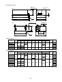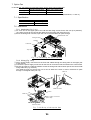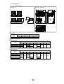
1
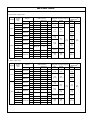
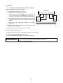
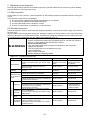
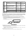
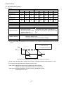
Instruction Manual DB Unit Dynamic Braking Unit 200V Series 37kW /BU37-2C to 90kW /BU90-2C 400V Series 37kW /BU37-4C to 220kW /BU220-4C CAUTION ■ Ensure that this instruction manual is made available to the final user of the DB unit. ■ Read and understand all operating instructions before installing, connecting (wiring), operating, maintaining or inspecting the DB unit. ■ Keep this manual up to disposing the DB unit carefully. ■ The product is subject to change without notice. INR-HF51196c-E Preface Thank you for purchasing our dynamic braking unit (DB unit). This product is a device to discharge the braking power to a resistor in a braking operation of the Fuji's inverter for general industry. The applicable inverter models should be referred to Table A. Read this manual carefully before using, understand the treatment method and use the DB unit correctly. Incorrect use may result in obstruction of normal operation, shortening of the life or cause of failure. Keep this manual carefully even after using. As this manual does not cover the use of inverter, refer to relevant manuals for the inverter to be used. Table A Applicable inverter models Series 200V General-purpose inverter 400V Vector inverter General-purpose inverter Vector inverter Model FRENIC5000 G5/P5,G7/P7,G9S/P9S,G11S/P11S series FRENIC-Eco series FRENIC5000 VG3,VG5,VG7S series FRENIC5000 G9S/P9S,G11S/P11S series FRENIC-Eco series FRENIC5000 VG5,VG7S series As following the old model is applicable to DB unit by special tuning before shipment, please contact your local distributor or nearest Fuji Electric's sales office. Series Model 200V Vector inverter FRENIC5000 VG series 400V General-purpose inverter FRENIC5000 G5/P5, G7/P7 series Vector inverter FRENIC5000 VG,VG3 series Safety instructions Read this manual carefully before installing, connecting (wiring), operating, maintaining, or inspecting the DB unit and use it correctly. Familiarize yourself with all knowledge of the device, safety information and instructions before using. In this manual, safety messages are classified as follows. Denotes operating procedures and practices that may result in personal injury or loss of life if not correctly followed. Denotes operating procedures and practices that may result in slight to medium personal injury or property damage if not correctly followed. Situation more serious than those covered by CAUTION will depend on prevailing circumstances. Always follow the instructions as important contents are described in these. WARNING CAUTION Instruction on use WARNING ・ This DB unit is designed to discharge the braking power to a resistor in a braking operation of the Fuji's inverter for general industry. It cannot be used for others. Fire may result. ・ This DB unit may not be used (as is) as a component of a life-support system or other medical device directly affecting the personal welfare of the user. ・ This product is manufactured under strict quality control standards. However, safety equipment must be installed if the failure of this device may result in heavy accident and/or property damage. There is a risk of accident. Instruction on installation WARNING ・ Mount this DB unit on an material such as metal. Fire may result. ・ Do not place combustible or flammable material near this DB unit。 Fire may result. ・ Contain the DB unit into a panel etc. so as not to be able to touch it easily. Electric shock or accident may result. ・ Ensure that the specified bolts are used when installing the DB unit. There is a risk of accident or injury. CAUTION ・ Do not hold the front cover when carrying the DB unit. Injury by dropping may result. ・ Ensure that the DB unit and cooling fins are kept free if foreign matters such as lint, paper, small chips of wood or metal, or dust. Fire or accident may result. ・ Do not install or operate a damaged DB unit or a DB unit missing parts. Injury may result. Instruction on wiring WARNING ・ Use wires of the specified size for wiring. Fire may result. ・ Do not connect the DC terminals (P(+) and N(-)) to the connection terminals on the inverter side in mistake for the polarity (+ and –). Fire may result. ・ Ensure that the grounding wire is connected. Electric shock or fire may result. ・ A licensed specialist must perform the wiring works. Electric shock may result. ・ Turn off the power before starting the wiring work. Electric shock may result. ・ Wire after the installation of the DB unit is complete. Electric shock or fire may result. CAUTION ・ Check that the rated voltage of the product complies with that of the inverter. Injury may result. ・ Do not directly connect DC terminals (P(+) and N(-)) to the braking resistor. Fire may result. ・ The DB unit and wiring generate noise. Take care the malfunction of the sensors and devices in surroundings. Accident may occur. Instruction on operation WARNING ・ Ensure that the power is turned on (close) after attaching the front cover. In energized status, do not remove the cover. Electric shock may result. ・ Do not touch the terminals of the DB unit in energized state of the inverter even if the inverter has stopped. Electric shock may result. CAUTION ・ Do not start and stop the inverter by turning on/off the main circuit power supply. Failure may result. ・ Do not touch the cooling fins and braking resistor since they become very hot. Burns may result. ・ The braking with this DB unit cannot function as mechanical holding. Injury may result. Instruction on maintenance, inspection, and parts replacement WARNING ・ Wait a minimum ten minutes after the power has been turned off (open) before starting inspection. Further, check that the charge lamp is turned off and that the DC voltage between the terminals P(+) and N(-) do not exceed 25V. Electric shock may result. ・ Only authorized personnel should perform maintenance, inspection, and replacement operations. Take off metal jewelry such as watches and rings. Use insulated tools. Electric shock or injury may result. Instruction on disposal CAUTION ・ Treat the DB unit as industrial waste when disposing it. Injury may result. Other instructions WARNING ・ Never modify the product. Electric shock or injury may result. Conformity to Low Voltage Directive in Europe CAUTION ・ Ensure that the DB unit is grounded. ・ When wiring to the main circuit terminals and terminal for grounding of the inverter, use round terminals for the cable. ・ Use a single cable to connect the grounding terminal G of the DB unit. (Do not use two or more wires for the wiring.) ・ Use the DB unit under overvoltage category III conditions and maintain Pollution degree 2 or better as specified in IEC 664. To maintain Pollution degree 2 or better, install the DB unit in a control panel (IP54 or higher level) having a structure free from water, oil, carbon, dust, etc. ・ For the input-output wiring of the DB unit, use cable (wire diameter and type) as specified in Appendix C in EN 60204. ・ To prevent electric shock at terminals or live parts, install the braking resistor as follows: 1) Install inside an IP4X cabinet or a barrier if electrical parts are exposed. 2) Install inside an IP2X cabinet or a barrier if electrical parts are not exposed. GENERAL ATTENTION Some illustrations in this manual are drawn in the status with removed cover or block for safety to describe in detail. When operating the product, ensure that the cover or block is returned to the original as the specification, and operate in accordance with the manual. Compliance with UL/cUL standards [Applicable to products with UL/cUL mark] ] 1.General UL(Underwriters Laboratories Inc.) standards is safety standards for prevention of fire and other accident, and protect user, maintenance man and people. UL standards cUL standards is fixed standards conform with CSA standards. The products approved by cUL is equivalent to approval of CSA. 2.Notice When using DB unit according to UL/cUL standards, please refer to following notice. CAUTION for UL/cUL requirements CAUTION ・ Hazard of electrical shock. Disconnect incoming power before working on this control. ・ Dangerous voltage exists until charge lights is off. ・ More than one live circuit. ・ Use 60/75℃ or 90℃ copper wire only. ・ A Class 2 circuit wired with class1 wire. ・ Field wiring connection must be made by a UL Listed and CSA Certified closed-loop terminal connector sized for the wire gauge involved. connector must be fixed using the crimp tool specified by the connector manufacturer. ・ For use with 3ph 200-220V/50Hz, 200-230V/60Hz Inverter Drives for models with suffix -2C. ・ For use with 3ph 380-440V/50Hz, 380-480V/60Hz Inverter Drives for models with suffix -4C. CAUTION Tightening torque and wire range 1.60℃/75℃ copper wire Voltage Applied Motor (kW) 30 TYPE BU37-2C 37 200V 45 TYPE Resistance value(Ω) Q’ty Main terminal Ground -ing 1 DB30-2C 4.0 1 1 DB37-2C 3.0 1 31.0 (3.5) 31.0 (3.5) 10 (5.3) Required torque [lb-inch](N.m) Braking resistor 1 DB45-2C 2.5 1 55 1 DB55-2C 2.0 1 75 1 DB75-2C 1.6 1 1 DB110-2C 1.2 1 1 DB30-4C 15 1 1 DB37-4C 12 1 1 DB45-4C 10 1 55 1 DB55-4C 7.5 1 75 1 DB75-4C 6.5 1 BU55-2C BU90-2C 90 30 BU37-4C 37 45 400V Q’ty Wire range [AWG] (mm2) Main Control Control terminal DB Unit BU55-4C BU90-4C 90 110 1 BU132-4C 132 160 200 BU220-4C 220 DB110-4C 4.7 15.9 (1.8) 51.3 (5.8) 1 DB132-4C 3.9 1 1 DB160-4C 3.2 1 1 DB200-4C 2.6 1 1 DB220-4C 2.2 1 119 (13.5) 31.0 (3.5) 4 (21.2) 14 (2.1) 6.2 (0.7) 12 (3.3) 51.3 (5.8) 10 (5.3) 119 (13.5) 119 (13.5) 6 (13.3) 239 (27) 239 (27) 3 (26.7) 1 1 1 119 (13.5) 8 (8.4) 24 (0.2) 2.90℃ copper wire Voltage Q’ty TYPE Resistance value(Ω) Q’ty Main terminal Ground -ing Wire range [AWG] (mm2) Main Control Control terminal 1 DB30-2C 4.0 1 1 DB37-2C 3.0 1 31.0 (3.5) 31.0 (3.5) 14 (2.1) 1 DB45-2C 2.5 1 55 1 DB55-2C 2.0 1 75 1 DB75-2C 1.6 1 1 DB110-2C 1.2 1 Applied Motor (kW) 30 DB Unit TYPE BU37-2C 37 200V 45 BU55-2C BU90-2C 90 30 400V Required torque [lb-inch](N.m) Braking resistor 1 DB30-4C 15 1 37 1 DB37-4C 12 1 45 1 DB45-4C 10 1 55 1 DB55-4C 7.5 1 75 1 DB75-4C 6.5 1 BU37-4C BU55-4C BU90-4C 90 1 110 1 BU132-4C DB110-4C 4.7 1 1 DB132-4C 3.9 1 160 1 DB160-4C 3.2 1 1 DB200-4C 2.6 1 1 DB220-4C 2.2 1 220 BU220-4C 15.9 (1.8) 51.3 (5.8) 119 (13.5) 31.0 (3.5) 6 (13.3) 6.2 (0.7) 14 (2.1) 51.3 (5.8) 12 (3.3) 119 (13.5) 119 (13.5) 8 (8.4) 239 (27) 239 (27) 4 (21.2) 1 132 200 119 (13.5) 10 (5.3) 24 (0.2) Contents 1 2 Before Using This Product 1-1 Inspection at receiving the unit 1-2 Appearance 1-3 Handling of the product 1-4 Carrying 1-5 Storage 1-1 1-1 1-2 1-2 1-2 Installation and Connection 2-1 Operating environment 2-2 Installation method 2-3 Connection 2-3-1 Basic connection 2-3-2 Connecting the main circuit and grounding terminal s 2-3-3 Connecting the control terminals 2-3-4 Terminal arrangement 2-3-5 Applicable devices and wire size as standard 2-1 2-1 2-1 2-2 2-2 2-4 2-5 2-7 2-8 3 Operation 3-1 Inspection and preparation before operation 3-1 3-1 4 Protective Operation 4-1 Protective operations 4-2 Alarm reset 4-1 4-1 4-1 5 Maintenance and Inspection 5-1 Daily inspection 5-2 Periodical inspection 5-3 Insulation test 5-4 Parts replacement 5-5 Inquiries about product and product guarantee 5-1 5-1 5-1 5-2 5-3 5-3 6 Specifications 6-1 Standard specifications 6-1-1 DB unit 6-1-2 Braking resistor 6-2 Outline dimensions 6-2-1 DB unit 6-2-2 Braking resistor 6-1 6-1 6-1 6-2 6-3 6-3 6-4 7 Option Fan 7-1 Specification 7-2 Attaching 7-2-1 Attaching 7-2-2 Wiring 7-3 Outline dimensions 7-3-1 Option fan unit 7-1 7-1 7-1 7-1 7-1 7-2 7-2 1 Before Using This Product 1-1 Inspection at receiving the unit Unpack and inspect the unit for the following items. If there are doubtable or complained items, contact the distributor where the unit was purchased or the Company's sales office nearby. Front cover ① Check for the unit to be the ordered product by inspecting the ratings nameplate. Under of Unit(Mounting bord) TYPE : Type of the dynamic braking unit Fig. 1-1-1 Ratings nameplate BU 37 - 4 C Standard series: C AC power supply voltage series: 2→200V series、4→400V series Rated output of the applied motor for the inverter as standard: 37→37kW Product type COOLING : Cooling system SOURCE : Power rating OUTPUT : Output rating MASS : Mass of the product SER.No. : Serial number 4 3 HH12345R678-001H Production lot serial number: Production month: 1--9 →Jan. --Sep. X→Oct. Y→Nov. Z→Dec. Production year : Last digit of year 8→1998 ② Inspect if shipping damage such as damage or fall-off of the parts and depression of the cover or body. ③ Braking resistor is not attached. Prepare a resistor conforming with the specification separately. 1-2 Appearance Front cover Warning label Nameplate Fig. 1-2-1 Appearance Fig. 1-2-2 Warning label 1-1 1-3 Handling of the product (1) Removing the front cover Loosen the mounting screws of front cover and remove the front cover by holding its upper part with hands as shown in Fig. 1-3-1. Mounting screws of front cover Fig. 1-3-1 Removing the front cover 1-4 Carrying When carrying the product, hold only the main body of the product surely. If holding the cover or parts, it may result in damage or fall-off. 1-5 Storage Storage the products in the environment as shown in Table 1-5-1. Table 1-5-1 Storage environment Item Specification Ambient. –10 to +50°C temperature The location without condensation or freezing by sharp ∗1 Storage temperature change –25 to +65°C temperature ∗2 Relative humidity 5 to 95% Without dust, direct sunlight, corrosive gas, inflammable gas, oil mist, vapor, Atmosphere water drop and vibration Not including too much of salt ∗1: The storage temperature means in a case of a short time such as transport. ∗2: Although the humidity conforms to the specified value, condensation or freezing occurs in a location of large temperature change. Avoid such location. ① Do not put the product directly on a floor. ② If the surrounding atmosphere is not good, store the product packed with a vinyl sheet etc. ③ If the humidity may affect the product, put a desiccant ( such as silica gel) into the package as shown in . 1-2 2 Installation and Connection 2-1 Operating environment Install the DB unit in the environment shown in Table 2-1-1. Table 2-1-1 Operating environment Item Specifications Location Indoor Ambient –10 to +50℃ temperature Relative 5 to 95% (no condensation) humidity Without dust, direct sunlight, corrosive gas, oil mist and vapor, water drop Atmosphere Not including too much of salt Without condensation by sharp temperature change 1,000m or less Altitude (When exceeding 1,000m, decrease the inverter output in accordance with Instruction Manual of the inverter.) 2 2 2 Vibration 3.0mm at 2 to 9Hz, 9.8m/s at 10 to 20Hz, 4.9m/s at 20 to 55Hz, 1.0m/s at 55 to 200Hz 2-2 Installation Method ① Securly fasten the DB unit in an upright position on a solid structure such that the characters of the label is facing the front. Do not turn the DB unit upside down or install in a horizontal position. ② As heat is generated during DB unit operation, the spaces shown in Fig. 2-2-1 are required to ensure sufficient cooling pass. As heat radiates upward, do not install the DB unit beneath a device sensitive to heat. Top 100m m Right Left 50mm or more ③ As the cooling fins may reach a temperature of 90℃ during DB unit operation, ensure that the material of the attaching face at back of the DB unit can withstand this temperature. DB Unit 50mm or more Bottom 100mm Fig. 2-2-1 WARNING Install the DB uint on nonflammable material such as metal. Fire may result. ④ When installing the DB unit in a control panel, consider sufficient ventilation to prevent ambient temperature of the DB unit from exceeding the specified value. Do not install in a small tightly closed box. ⑤ If installing two or more inverters or DB units in the same device or control panel, arrange them horizontally to minimize the effect of heat. If they must be installed vertically, place isolation plates between them to minimize the effect of heat. CAUTION Ensure that the DB unit and cooling fins are kept free of foreign matter such as lint, paper dust, small chips of wood or metal, and dust. Fire or accident may result. 2-1 2-3 Connection When removing the front cover, the terminal blocks appear (see Fig. 2-3-1). Connect the cables without mistake caring the following items. 2-3-1 Basic connection ① Connect the link circuit connection terminals (P(+), N(-)) of the DB unit to the link circuit connection terminals (P(+), N(-)) of the inverter. If mistaking the polarity or connecting to the other terminal, the DB unit may be damaged. Further, check the power supply voltage for conforming to the inverter specification. ② Ensure to ground the grounding terminal to prevent disasters such as electric shock and fire and to minimize noise. ③ Use a reliable crimp terminal for connection between a terminal and a cable. ④ After terminating the connection (wiring), check the followings: a. Check that the connection is correct. b. Check that all necessary connections have been made. c. Check that there is no short-circuit or ground fault between terminals and cables. ⑤ Connection modification after power-on The smoothing capacitor in the direct current portion of the main circuit cannot be discharged immediately after the power is turned off. To ensure safety, use a multimeter to check that the voltage of the direct current (DC) is lowered to the safety range (25V DC or less) after the charge lamp goes off. Also, check that the voltage is zero before short-circuiting. The residual voltage (electric charge) may causes sparks. WARNING ・ Always connect a grounding wire. Electric shock or fire may result. ・ Ensure that a licensed specialist performs all wiring works. ・ Check that the power is turned off (open) before commencing wiring operations. Electric shock may result. Front view of inside the unit Fig. 2-3-1 Front view after removing the front cover 2-2 ■ Basic connection diagram 1) In case of using one DB unit and one braking resistor Wire length 10m or less Wire length 5m or less Inverter DB unit P1 P(+) Braking resistor P(+)R P DB DB P(+) + + M (*4) CHARGE G 1 N(-) Main circuit N(-) 1 2 3 G i1 i2 o1 o2 2 SW1 CN5,6 Option fan 1 2 (*2) Control circuit External (*1) alarm Input CM Fig. 2-3-2-1 2) In case of using two DB units and two braking resistors (∗3) Wire length 10m or less Wire length 5m or less Inverter P1 DB unit[Master] P(+) Braking resistor P(+)R P DB DB P(+) + + M (*4) CHARGE G 1 N(-) Main circuit N(-) 1 2 3 G i1 i2 o1 o2 Control circuit External (*1) alarm Input 2 SW1 CN5,6 Option fan 1 2 Wire length 1.5m or less CM (*2) Applied inverter series 200V class FRENIC5000 G5/P5,G7/P7,G9S/P9S ,G11S/P11S series FRENIC-Eco FRENIC5000 VG3,VG 5,VG7S 400V class FRENIC5000 G9S/P9S ,G11S/P11S series FRENIC-Eco FRENIC5000 VG5,VG7S i1 i2 o1 o2 1 2 3 Option fan 1 2 SW1 CN5,6 P(+)R P DB DB 2 1 P(+) + CHARGE N(-) G DB unit[Slave] G Braking resistor Fig. 2-3-2-2 (∗1) Among the inverters. assignment to the digital input terminals can be arbitrarily changed in some inverters. Select the external alarm input by function setting. (∗2) Do not short-circuit the not using terminals of the control PCB in the DB unit. (∗3) The parallel connection of the DB units is up to two units. When necessary to connect 3 or more DB units, contact us separately. (∗4) Connect a lump-sum alarm output of the DB unit and braking resistor to the external alarm input, and construct a sequence to open the electromagnetic contactor by the lump-sum alarm output of the inverter. 2-3 2-3-2 Connecting the main circuit and grounding terminals Table 2-3-1Functions of the main circuit terminals and grounding terminal Terminal Name of terminal Description marking P(+), N(-) DC link circuit terminals Connecting to the DC link circuit voltage of the inverter Connection terminals for Connecting to the braking resistor P(+)R, DB braking resistor G Terminal for grounding DB unit Grounding terminal of the chassis (case) of the DB unit (1) DC link circuit terminals (P(+) and N(-)) ① Connect the DC link circuit terminals P(+) and N(-) of the inverter to the terminals P(+) and N(-) of the DB unit. ② Arrange the wire rout so that the wire length is less than 5m. Further, arrange the two wires to be twisted or closely contacted (parallel) wiring. ③ Do not connect to an AC power supply. (2) Connection terminals for braking resistor (P(+)R and DB) ① Connect the terminals P and DB of the braking resistor to the terminals P(+)R and DB of the DB unit. ② Arrange the wire rout so as the wire length is less than 10m. Further, arrange the two wires to be twisted or closely contacted (parallel) wiring. ③ Do not connect to an AC power supply. (3) Terminal for grounding DB unit ( G) Ensure that the terminal G for grounding DB unit is grounded because of safety and countermeasure for noise. To prevent disasters such as electric shock and fire, the Electric Facility Technical Standard specifies on the grounding work for a metallic frame of electrical equipment. Perform the connection as follows: ① In accordance with the Electric Facility Technical Standard, connect the terminal to a grounding pole made by type D grounding for 200V series and to a grounding pole made by type C grounding for 400V series. ② Use a suitable cable (thick and short) to connect the grounding terminal to the grounding pole specific for the inverter system. Table 2-3-2 Voltage series 200V 400V Sort of the grounding work CAUTION Type D grounding Type C grounding Grounding resistance 100Ωor less 10Ω or less ・ Do not connect an AC power supply to the DC link circuit terminals (P(+) and N(-)). Damage may result. ・ Do not directly connect the braking resistor to the DC link circuit terminals (P(+) and N(-)). ・ Check that the product specification complies with the inverter to be connected. ・ When the DB unit is damaged, the braking resistor may abnormally heated. Make a sequence to interrupt the power supply on the inverter side by an alarm signal. Fire may result. 2-4 2-3-3 Connecting the control terminals Function descriptions of the control terminals are shown in Table 2-3-3. Table 2-3-3 Terminal marking Name of terminal Function description Connecting the DB drive signal wire of the unit on the slave unit (∗1) side when using the units in parallel Connecting the DB drive signal wire of the unit on the DB driving signal output terminals o 1, o 2 master unit (∗2) side when using the units in parallel Outputting the alarm for overheat and blown fuse of 1, 2 DB unit lump-sum alarm output DB driving IGBT and braking resistor, and conduction abnormal of DB driving IGBT Connectors for power supply of Connecting power supply of option fans when installing CN5, CN6 option fans them (∗1) The unit operating by receiving DB driving signal from the unit on the master side (∗2) The unit operating by detecting DB operation level by itself from the link circuit voltage i1, i2 DB driving signal input terminals (1) DB driving signal input terminals (i1 and i2) DB driving signal output terminals ( o 1 and o 2) ① These terminals connect between master and slave when using 2 DB units. ② To reduce the noise effect from outside, use twisted wires as short as possible (1.5m or less). ③ Change over the settings of master and slave in the DB units with SW1 on the PCB as shown in Fig. 2-3-3. ④ When using single DB unit, set the SW1 as shown in a). ⑤ Do not short-circuit not used terminals. (2) DB unit lump-sum alarm output (1 and 2) ① Connect the terminals of the DB units and braking resistors in series in the order of 1212 to the contact input terminals of the inverter which are assigned external alarm input to. When used a short-circuit conductor on the contact input terminals to be connected on the inverter side, remove the short-circuit conductor. (3) Connectors for power supply of option fans (CN5 and CN6) ① When using option fans, the power supply lines of the fans are connected to these terminals. ② Connectors CN5 and CN6 have a same function. ③ Do not short-circuit these connectors because of power supply connection. a)Unit connecting the terminals o1 and o2(Master side) SW1 1 2 3 SW1 b)Unit connecting the terminals i1 and i2(Slave side) SW1 1 2 3 SW1 Fig. 2-3-3 Changeover of SW1 Switch SW1 Control (4) Others circuit block ① Perform the wiring of the control terminals separating from the wiring of the main circuit as far as possible. Otherwise, malfunction by noise may be caused. ② Fix the control wiring inside the unit so as not to directly CN5 CN6 contact with a live part of the main circuit (e. g. main circuit terminal block). Fig 2-3-4 Control PCB ③ The parallel connection of the DB units is up to two units. When necessary to connect 3 or more DB units, contact us separately. • Since the insulation of control cable is generally not of reinforced insulation, high voltage may intrude into the control signal if insulation sheath is broken by any cause. Electric shock may result. • A noise is generated from inverter, motor,wiring. etc. Take care on malfunction of sensors and devices in the surroundings. • Be sure not to move the setting of the variable resistor VR1 on the control PCB since it has been adjusted. Accident may result. WARNING CAUTION 2-5 (5) Wiring of the control circuit ① Lead out the cable along the left side panel as shown in Fig. 2-3-5. ② Secure the cable to cable-tie holder on the left wall of the main circuit terminal block on the way of lead out using a cable-tie (e. g. insulock). The cable-tie must not exceed 3.5mm or less in width and 1.5 mm or less in thickness to pass through a rectangular hole (3.8×1.5). Cables of control circuit Cable-tie Cables Cable-tie holder Side panel (LEFT) Fig. 2-3-5 Route of control circuit wiring 2-6 2-3-4 Terminal arrangement (1) Main circuit terminals BU220-4C BU37-2C Screw size M5 P(+) N(-) P(+)R Screw size M10 DB P(+) N(-) P(+)R DB G G G Screw size M5 BU37-4C (2) Control terminals Screw size M4 P(+) N(-) Screw size M3 P(+)R DB i1 G G Screw size M5 BU55-2C Screw size M8 P(+) N(-) P(+)R DB G G Screw size M8 BU55-4C Screw size M6 P(+) Screw size M6 N(-) G G P(+)R DB Screw size M5 BU90-2C BU-132-4C Screw size M8 P(+) N(-) G P(+)R DB G BU90-4C Screw size M6 P(+) G N(-) G G P(+)R DB 2-7 i2 o1 o2 1 2 2-3-5 Applicable devices and wire size as standard Voltag e 200V 400V Applied motor (kW) 30 37 45 55 75 90 30 37 45 55 75 90 110 132 160 200 220 DB unit Type BU37-2C BU55-2C BU90-2C BU37-4C BU55-4C BU90-4C BU132-4C BU220-4C Tightening torque Recommended wire size 2 (N・m) (mm ) ∗1) Resistance Main GroundDB cct.(P(+), Ground. No. Control Control N(-),P(+)R,DB) ( G) circuit ing value (Ω) 4.0 1 2 3.5 3.0 1 3.5 2.5 1 1.25 0.7 2.0 1 5.5 13.5 1.6 1 8 1.2 1 14 15 1 1.8 12 1 3.5 2 10 1 5.8 7.5 1 6.5 1 3.5 1 0.7 1.25 4.7 1 13.5 5.5 3.9 1 3.2 1 8 2.6 1 27 14 2.2 1 Braking resistor No. Type 1 1 1 1 1 1 1 1 1 1 1 1 1 1 1 1 DB30-2C DB37-2C DB45-2C DB55-2C DB75-2C DB110-2C DB30-4C DB37-4C DB45-4C DB55-4C DB75-4C DB110-4C DB132-4C DB160-4C DB200-4C 1 DB220-4C ∗2) ∗1) The type of using wire is 75°C 600V Grade heat-resistant polyvinyl chloride insulated wire (HIV). The above-mentioned wire sizes are the recommended size under the condition of the ambient temperature 50°C or lower. ∗2) A DB220-4C set is constructed by 2 cabinets. These 2 resistors are used connecting in parallel. 2-8 3 Operation 3-1 Inspection and preparation before operation Inspect the following items before operation DB unit ① Check that the connection is correct. In particular, check the following points: G, P(+), N(-), P(+)R, DB a. Check that the AC power supply is not connected to any of DC link circuit terminals P(+) and N(-) or connection terminals for braking resistor P(+)R and DB. DB P(+) P b. Check that the DC link circuit voltage is not connected to the connection terminals for braking resistor P(+)R and DB. N(-) Inverter c. Check that grounded. Fig. 3-1-1 DB unit connection diagram the grounding terminal is securely Braking resister ② Check for short-circuits and ground faults between the terminals and live sections. ③ Check for loose terminals, connectors, or screws. Check the followings after power-on. ① Check that no external alarm message is displayed on the inverter. ② Check that the CHARGE lamp is turned off. ③ Check that the fans are rotating (when using option fans). WARNING • Be sure to put on the front cover before turning on the power (close). Never remove the cover while the power is applied to the inverter. Electric shock may result. 3-1 4 Protective Operation 4-1 Protective operations In the event of abnormality as shown in Table 4-1, the DB unit stops DB driving signal and outputs a lump-sum alarm signal from the terminals 1 and 2 (The lump-sum alarm signal has no distinction of the abnormality contents.). By this alarm signal, the protective function of the inverter will be immediately activated to trip the inverter and display the external alarm on the keypad panel, and the motor coasts-to-a stop. Since the braking resistor may be overheated when the DB unit is out of order, construct a sequence to trip the power supply in the case of activation of the inverter protective function. Table 4-1 Abnormality Blown fuse Contents If the fuse in the main circuit of the DB unit is blown out following a short-circuit in the circuit or damage, the protective function is activated. Overheating of the If the cooling fins overheat following frequent use of braking exceeding the cooling fins specification, high ambient temperature or clog of the fins, the protective function is activated. Conduction abnormal of If detecting conduction of IGBT (switching element) although stopping of the DB IGBT(switching element) driving signal, the protective function is activated. Overheating of the If the braking resistor overheats following high-frequent use of the braking braking resistor resistor, the protective function is activated. 4-2 Alarm reset If becoming the trip status, release the trip in accordance with the instruction of the inverter Instruction Manual after removing the cause of the trip. When releasing the trip status, set the operation command to OFF. Take care, if the operation command is set to ON, the inverter starts operation after resetting. WARNING If the alarm reset is activated with the operation signal ON, the inverter will restart suddenly, which may be dangerous. To ensure safety, release the trip status after checking the operation signal OFF. Accident may result. 4-1 5 Maintenance and Inspection Proceed with the daily inspection and periodic inspection to prevent malfunction and ensure long-term reliability. Note the followings in the inspection works. 5-1 Daily inspection During opera t ion of the inverter, a visual inspection for abnormality is performed externally without removing the covers. The inspection usually covers the followings: ① The performance (satisfying the standard specification) is as expected. ② The environment satisfies the standard specification. ③ There are abnormal sounds, vibrations, or odors. ④ There are no indications of overheating or no discoloration. 5-2 Periodical inspection Periodical inspection must be performed after stopping operations, turning off the power supply, and removing the front cover. Note that after turning off the power supply, the smoothing capacitor in the DC section in the main circuit takes the time to discharge. To prevent electric shock, check that the voltage has dropped below the safety value (25V DC or below) using a multimeter after the charge lamp (CHARGE) goes off. • Start the inspection at least ten minutes after turning off the power supply. Further check that the charge lamp (CHARGE) goes off, and that the voltage is 25V DC or below between the terminals P(+) and N(-). Electric shock may result. • Only authorized personnel should perform maintenance and component replacement operation. Take off metal jewelry such as watches and rings. Use insulated tools. Never modify the product. Electric shock or injury may result. WARNING Table 5-2-1 Periodical inspection list Check part Environment Voltage Check items How to inspect Check the ambient temperature, humidity, vibration, atmosphere (dust, gas, oil mist, water drops). Is the area surrounding the equipment is clear without left foreign body such as tool or dangerous body. Are the voltages in the main and control circuits normal? Is there abnormal sound or vibration? Main circuit Structure such Are nuts or bolts loose? as a frame or Is there deformation or damage? cover Is there discoloration as a result of overheating? Are there stains and dust? Are there loose or missing nuts or bolts? Are there deformation, crack, damage, and Common discoloration due to overheating or deterioration in the equipment and insulation? Are there stains and dust? Is there discoloration or distortion a conductor Conductor due to overheating? Are there cracks, crazing or discoloration of the and wire cable sheath? Terminal block Is there damage? Evaluation criteria Conduct visual inspection and use the meter. The specified standard value must be satisfied. Visual inspection The area is clear. Measure using the multimeter. Visual and aural inspection Tighten. The specified standard value must be satisfied. Not abnormal Visual inspection Not abnormal Tighten. Not abnormal Not abnormal Note: Discoloration of the bus bar does not indicate a problem. Visual inspection Not abnormal Visual inspection Not abnormal Visual inspection Not abnormal Visual inspection Not abnormal Is there electrolyte leakage, discoloration, Smoothing crazing or swelling of the case? capacitor Is the safety valve not protruding or are valves protruding too far? 5-1 Cooling circuit Control circuit Main circuit (continued) Is there unusual odor or damage to the insulation Olfactory and visual by overheating? inspection Conduct a visual Resistor inspection or use a Is there an open circuit? multimeter by removing the connection on one side. Are there any loose screws or connectors? Tighten Is there unusual odor or discoloration? Control Olfactory and visual Are there cracks, damage, deformation, or PCB and inspection excessive rust? connector Is there electrolyte leakage or deformation to the Visual inspection capacitor? Aural and visual inspection. Turn it Is there abnormal sound or vibration? manually. (Check the Cooling fan power supply is off.) Are nuts or bolts loose? Tighten Is there discoloration due to overheating? Visual inspection Is there foreign matter on the fins or intake and Ventilation Visual inspection exhaust ports? Not abnormal Less than about ±10% of the indicated resistance value Not abnormal The fan must rotate smoothly. Not abnormal Not abnormal Not abnormal Note: If the equipment stained, wipe with a cleaning cloth of chemical neutrality. Vacuum the dust. 5-3 Insulation test Avoid testing the DB unit with a megger because an insulation test is completed at the factory. If a megger test must be conducted, proceed as described below. Use of an incorrect test method may result in product damage. If the specifications for dielectric strength test are not followed, the product may be damaged. If a dielectric strength test must be performed, contact your local distributor or nearest Fuji Electric's sales office. (1) Megger test for the main circuit ① Use a 500V DC type megger and isolate the main power supply before commencing measurement. ② If the test voltage is applicable to the control circuit, remove all connection cables to the control circuit. ③ Connect the main circuit terminals using common cables as shown in Fig. 5-3-1. ④ Execute the megger test only between the common cables connected to the main circuit and the ground (terminal G). ⑤ A megger indicating 5MΩ or more is normal. (This is the value measured with a DB unit only.) G N(-) - + - P(+) P(+)R DB + Megger Fig. 5-3-1 Megger test (2) Insulation test for the control circuit A megger test and a dielectric test must not be performed in the control circuit. Prepare a high resistance range multimeter for the control circuit. ① Remove all external cables from the control circuit terminals. ② Conduct a continuity test between the control circuits and the ground. A result of 1 MΩ or more is normal. (3) Exterior main circuit and sequence control circuit Remove all cables from the terminals to ensure the test voltage is not applied to the DB unit. 5-2 5-4 Parts replacement Each part has a life determined by the sort of the part. Since the life expectancy of a part differs depending on the environment and using conditions. It is recommended to replace parts at the timing shown in Table 5-4-1 as standard. As for replacement method, contact your local distributor or nearest Fuji Electric's sales office separately. Table 5-4 Parts replacement Part name Cooling fan Smoothing capacitor Electrolytic capacitor on the PCB Fuse Other parts Standard period Comments for replacement 3 years Exchange for a new part Exchange for a new part 5 years (determined after checking) Exchange for a new part 7 years (determined after checking) 10 years Exchange for a new part Determined after checking - 5-5 Inquiries about product and product guarantee (1) Inquiries If there is damage or failure in the product, or questions concerning the product, contact your local distributor or nearest Fuji Electric's sales office with following items. a. DB unit type b. SER NO.(Manufacturer's serial number)) c. Purchased time d. Inquiry details (e. g. location and extent of damage, questions, and status of failure) (2) Product guarantee The product guarantee term is one year after purchase or 18 month from the year and month of manufacture on the nameplate, whichever expires first. However, the guarantee will not apply in the following cases, even if the guarantee term has not expired. ① Damage was caused by incorrect use or inappropriate repair and modification. ② The product was used outside the standard specified range. ③ Damage was caused by dropping the product or damage during transportation after purchasing. ④ Damage was caused by an earthquake, fire, storm and flooding, lightening, abnormal voltage or other natural calamities and their secondary disasters. 5-3 5-4 6 Specifications 6-1 Standard specifications 6-1-1 DB unit Series 200V 400V Type BU37-2C BU55-2C BU90-2C BU37-4C BU55-4C BU90-4C BU132-4C BU220-4C Min. connectable 3.0 2.0 1.2 12 7.5 4.7 3.0 1.9 resistance (Ω) Max. braking power 37 56 90 37 56 90 135 240 (kW) Generated loss 40 50 60 35 40 50 60 80 (10%ED) (W) Rated current 25 37 61 12 19 31 47 79 (A r.m.s) Mass (kg) 4 6 9 4 5.5 5.5 9 13 Braking torque 100% (at standard applying to G11S) Duty factor 10%ED (30%ED when using option fans) ∗1, ∗2 Braking time 10s: Period of 100s (30s when using option fans) ∗1, ∗2 Operating voltage (V) 365 758 When detecting abnormalities described left, • Blown fuse the operation of the IGBT in the DB unit is • Cooling fin overheat • Abnormal operation of IGBT stopped, and an alarm is output to the inverter Protection function unit (Switching element) • Braking resistor overheat Cooling system Self-ventilation (forced ventilation when using option fans) Indoor Installation location Altitude of 1000m or less Free from corrosive gas. dust and direct sunlight Ambient temperature −10℃ to +50℃ ∗1) Duty factor (%ED) and braking time are converted into the condition of deceleration braking as shown below. Duty factor %ED=( T1/T0 ) X 1 00% T1 : Braking time (10s) Braking power T0 : Repetitive period (100s) Max. Braking power T1 T1 T0 The rated current value is an r.m.s value of the current in TD section. ∗2) When using the option fans, the duty factor (%ED) is calculated making the braking time (T1) 30s. ※ This DB unit are applicable to the following inverter units. ・200V series: FRENIC5000 G5/P5,G7/P7,G9S/P9S,G11S/P11S series FRENIC-Eco series, FRENIC5000 VG3,VG 5, VG7S series ・400V series: RENIC5000 G9S/P9S,G11S/P11S series, FRENIC-Eco series FRENIC5000 VG5 series 6-1 6-1-2 Braking resistor 200V series Type DB30-2C DB37-2C DB45-2C DB55-2C DB75-2C DB110-2C Nominal applied 30 37 45 55 75 90,110 motor (kW) Resistance value 4.0 3.0 2.5 2.0 1.6 1.2 (Ω) Max. capacity (kW) 30 37 45 55 83 113 Flowing current (A) 19 25 30 37 48 61 Mass (kg) 10 13 18 22 35 32 400Vseries Type DB30-4C DB37-4C DB45-4C DB55-4C DB75-4C DB110-4C DB132-4C DB160-4C DB200-4C DB220-4C Nominal applied 30 37 45 55 75 90,110 132 160 200 220 motor (kW) Resistance value 15 12 10 7.5 6.5 4.7 3.9 3.2 2.6 2.2 (Ω) Max. capacity (kW) 30 37 45 55 83 113 135 165 200 240 Flowing current (A) 10 12 15 19 24 34 41 50 62 71 Mass (kg) 11 14 19 21 26 30 41 57 43 74 Duty factor Braking time Ambient temperature 10%ED (refer to DB unit standard specifications ∗1) ∗3 10s: Period of 100s (refer to DB unit standard specifications ∗1) ∗4 −10°C to +50°C ∗3) When using option fans, the duty factor become 30%ED. ∗4) When using option fans, the braking time becomes 30s. 6-2 6-2 Outline dimensions 6-2-1 DB unit FIG. B 図B 2-ØC C W2 H4 H2 H1 H W2 H3 D1 H1 W H4 H3 W1 D H2 ØC W D1 C M OU NT IN G D IM EN SIO NS 取付寸法 M OU NT ING DIM EN SIONS 3- 取付ボルト HO LE S FO R FIXIN G BOLTS 取付寸法 4- 取付ボルト HO LES FO R FIXING BO LTS W2 H1 H1 W3 D H FIG. A 図A W2 [200 V series] TYPE BU37-2C BU55-2C BU90-2C FIG A B DIMENSIONS W W1 W2 W3 H 150 75 100 50 240 230 130 - - 250 150 370 [mm] H1 H2 225 210 355 340 H3 H4 7.5 15 D 160 D1 1.2 BOLT MASS (kg) M5 4 6 9 BOLT MASS (kg) C 6 2.4 [400 V series] TYPE BU37-4C BU55-4C BU90-4C BU132-4C BU220-4C DIMENSIONS FIG W W1 W2 W3 150 100 B 230 250 - 130 150 [mm] H H1 H2 280 265 250 H3 H4 D D1 C 4 - 1.2 7.5 15 160 370 450 355 435 340 420 6-3 6 2.4 M5 5.5 9 13 6-2-2 Braking resistor Main circuit Terminal Control circuit Terminal 1. 6 H FIG. A W1 D1 4- φ C W D Control circuit Terminal Main circuit Terminal H H1 FIG. B W1 W D1 4- φ C D [200V series] TYPE DB30-2C DB37-2C DB45-2C DB55-2C DB75-2C DB110-2C FIG A B W 660 750 450 550 DIMMENSIONS [mm] W1 H H1 140 628 — 240 718 420 283 43 520 SCREW D D1 C MAIN CONTROL CIRCUIT CIRCUIT BOLT M5 400 368 10 M4 M8 M3.5 M10 M6 440 250 12 M8 MASS [kg] 10 13 18 22 35 32 [400V series] TYPE FIG W DIMMENSIONS [mm] W1 H H1 140 628 — 240 718 SCREW D D1 C MAIN CONTROL CIRCUIT CIRCUIT DB30-4C M4 660 420 DB37-4C A 388 10 M4 DB45-4C M5 DB55-4C 750 425 DB75-4C M8 550 520 DB110-4C DB132-4C 650 620 283 43 440 250 12 B M3.5 DB160-4C M10 750 720 DB200-4C DB220-4C※ 600 570 ※ DB220-4C becomes a product with two blocks of the above-mentioned size. 6-4 BOLT MASS [kg] 11 14 M8 19 21 26 30 41 M10 57 43 74(37×2) 7 Option Fan In this DB unit, the braking time and duty factor can be rise by using option fans. Standard specification When using option fans Braking time 10s 30s Duty factor 10%ED 30%ED (Refer to Chapter 6 DB unit standard specifications, ∗1 and ∗2) 7-1 Specification Type Mass Ambient temperature BU-F 230g −10°C to +50°C 7-2 Attachment 7-2-1 Attachment (Fig. 7-2-1) ① Fix a fan unit on the upper part of the UB unit with fixing screws for the fan unit (at 2 positions). (The fixing screws for the fan unit are attached on the upper part of the fan unit.) ② Since the wiring hole is closed, open the hole so that the cable can pass through. Optional Fan unit Fixing screws Cables Inlet hole Top cover Fig. 7-2-1 Attaching the option fan unit 7-2-2 Wiring (Fig. 7-2-2) ① Pull in power supply connectors for the fans with cables through the wiring hole on the upper part of the UB unit. ② Connect the power supply connectors for the fans to connectors CN5 and CN6 on the control PCB. ③ Secure the cable to a cable-tie holders at near the wiring hole and left lower part of the control PCB using cable-ties (e.g. insulock). The cable-tie must not exceed 3.5 mm or less in width and 1.5mm or less in thickness to pass through a rectangular hole (3.8×1.5). Cable-tie Cables Cable-tie holder Cables Cable-tie Power supply C onnectors (CN5, CN6) Cable-tie holder Fig. 7-2-2 Wiring of the option fans 7-1 7-3 Dimensions 7-3-1 Option fan unit FAN UNIT DB UNIT + FAN UNIT W W5 D D3 H6 W6 H5 H H7 L D2 W4 [Fan unit] TYPE BU-F W4 149 DIMENSIONS H5 D2 44 76 [mm] L(Power supply) 320 [DBunit + Fan unit] [200V series] TYPE BU37-2C+BU-F BU55-2C+BU-F BU90-2C+BU-F W 150 230 250 W5 135 DIMENSIONS W6 H H6 7.5 240 30 47.5 57.5 370 H7 270 D D1 [mm] D3 160 1.2 64 D D1 [mm] D3 160 1.2 64 400 [400V series] TYPE BU37-4C+BU-F BU55-4C+BU-F BU90-4C+BU-F BU132-4C+BU-F BU220-4C+BU-F W 150 230 250 W5 135 DIMENSIONS W6 H H6 7.5 280 47.5 30 370 57.5 450 7-2 H7 310 400 480 D1 Edition history Edition – a b c Date of issue Sep. 1999 Oct. 2001 Oct. 2003 May 2004 Content First edition Correct : Section 2 Fig 2-3-3(Terminal Name) Change the corporation name Change the corporation logotype Change the “Table A Applicable inverter models” Add the “Compliance with UL/cUL standards[Applicable to products with UL/cUL mark]” Correct : Section 2-3-1 Fig.No. Fig.2-3-2 → Fig.2-3-2-1, Fig.2-3-3 → Fig.2-3-2-2 Section 6-2-2 FIG. B(Terminal Name) Preface, Section 2, Section 5, Section 6, Section 7 Misprint Gate City Ohsaki, East Tower, 11-2, Osaki 1-chome Shinagawa-ku, Tokyo 141-0032, Japan Phone: +81-3-5435-7139 Fax: +81-3-5435-7458 2