1
CHARON™ CHAPI for Windows
Version: 4.2
CHAPI Design Manual
©2006 - 2012 Stromasys SA
© 2006 - 2012 Stromasys SA
Under the copyright laws, this manual and the software described within are
intellectual property of Stromasys. This document may be copied or
translated for non-profit purposes, provided that the content is not modified
and this copyright notice is included in every copy or translation.
User Manual for CHARON™ W32, an API based system emulator for 32 bit
Windows host systems.
Document number: 30-16-040-001
02 April 2012
ii
Ownership Notice
Stromasys SA owns the rights, including proprietary rights, copyrights, trademarks, and
world-wide distribution rights to a methodology for the execution of applications and
system software by emulating the original hardware components of a legacy system in
software and/or microcode. This methodology is based on a portable software architecture
henceforth referred to as CHARON™.
Stromasys makes no representations that the implementation of the CHARON software
architecture as described in this publication will not infringe on existing or future patent
rights, nor do the descriptions contained in this publication imply the granting of licenses to
make, use, or sell equipment or software in accordance with the description.
Trademarks
The CHARON name with logo is a trademark of Stromasys. VAX, Q-bus, VMS and
OpenVMS are trademarks of The Hewlett-Packard Company. Windows is a registered
trademark in the United States and other countries, licensed exclusively through Microsoft
Corporation, USA. All other trademarks and registered trademarks are the property of their
respective holders.
Life support applications
The CHARON products from Stromasys are not designed for use in systems where
malfunction of a CHARON product can reasonably be expected to result in a personal
injury. Stromasys’ customers using or selling our CHARON products for use in such
applications do so at their own risk and agree to fully indemnify Stromasys for any
damages resulting from such improper use or sale.
iii
Contents
CONTENTS .................................................................................................. IV
PREFACE ..................................................................................................... X
SUMMARY ................................................................................................... XI
THIS MANUAL IS FOR... ........................................................................... XIII
CONVENTIONS ......................................................................................... XIV
1. CHAPI FUNCTIONALITY ........................................................................ 15
1.1
CHAPI overview ............................................................................................. 15
1.2
The CHARON CHAPI system components .................................................. 15
1.2.1
CHAPI components shared by CHARON-VAX and CHARON-PDP emulators: .................................. 16
1.2.2
CHAPI Development libraries .............................................................................................................. 18
1.2.3
The CHARON drivers used by CHAPI modules .................................................................................. 18
1.3
The CHAPI CHARON utilities ........................................................................ 19
1.3.1
The CHARON CHAPI device creation wizard ...................................................................................... 19
1.3.2
HOSTprint ............................................................................................................................................ 19
1.4
CHARON-PDP and CHARON-VAX with CHAPI support. ............................. 19
1.5
CHAPI based components provided with CHARON-VAX or CHARON-PDP.
20
1.5.1
Loading the CHAPI components ......................................................................................................... 20
1.5.2
The CHAPI device list .......................................................................................................................... 20
DH11 ..................................................................................................................... 20
DHV11 .................................................................................................................. 22
DLV11 ................................................................................................................... 24
DPV11 ................................................................................................................... 27
DR11(C) / DRV11 VIA SENSORAY 621 .......................................................... 29
DRV11-WA VIA SENSORAY 621 .................................................................... 30
DRV11-WA .......................................................................................................... 31
HTIME.................................................................................................................. 32
IAV1S-AA, IAV1S-C / IAV1S-CA ..................................................................... 32
IAV1S-B ................................................................................................................ 34
MRV11 .................................................................................................................. 35
QBUS ADAPTER BASED ON BCI-2104 PCI BOARD ................................. 36
iv
QBUS ADAPTER BASED ON PCIS3BASE PCI BOARD ............................ 37
RL11/RLV12 ........................................................................................................ 39
TS11/TSV05 ......................................................................................................... 40
VT30-H ................................................................................................................. 42
VT30-TV ............................................................................................................... 43
THE UNIBUS ADAPTER .................................................................................. 43
THE VCB02 GRAPHIC CONTROLLER ........................................................ 44
THE LPV11 .......................................................................................................... 44
2. CHAPI PROGRAMMING CONCEPTS .................................................... 46
2.1
Overview ......................................................................................................... 46
2.2
Loadable component naming conventions ................................................. 46
2.3
Component loading and initialization .......................................................... 47
2.4
Communication context binding .................................................................. 48
2.5
Run-time communication .............................................................................. 49
2.6
Notes on threading ........................................................................................ 51
3. THE CHAPI COMMUNICATION CONTEXT DESCRIPTORS ................. 52
3.1
The CHAPI_IN communication context descriptor ..................................... 52
3.2
The CHAPI_OUT communication context descriptor ................................. 68
3.3
Initialization steps .......................................................................................... 72
3.4
Run-time execution contexts ........................................................................ 72
4. CHAPI OPERATION ............................................................................... 75
4.1
Reading the device control and status register .......................................... 75
4.2
Writing device control and status register .................................................. 75
4.3
Creating additional I/O space ....................................................................... 75
4.4
Destroying I/O space ..................................................................................... 76
4.5
Changing I/O space bus location ................................................................. 77
4.6
Disconnecting I/O space ............................................................................... 78
4.7
Connecting I/O space .................................................................................... 78
4.8
The legacy way to process interrupts .......................................................... 79
4.8.1
Requesting a bus interrupt................................................................................................................... 79
4.8.2
Removing a bus interrupt request........................................................................................................ 79
4.8.3
Bus interrupt acknowledge .................................................................................................................. 80
4.9
The recommended way to process interrupts ............................................ 81
4.9.1
Connect bus request to the bus ........................................................................................................... 81
4.9.2
Set bus request.................................................................................................................................... 82
v
4.9.3
Clear bus request ................................................................................................................................ 82
4.9.4
Enable/disable bus request ................................................................................................................. 83
4.9.5
Get interrupt vector .............................................................................................................................. 83
4.9.6
Set interrupt vector .............................................................................................................................. 84
4.9.7
Set bus request affinity mask............................................................................................................... 84
4.9.8
Set bus request affinity callback .......................................................................................................... 85
4.9.9
Get bus server mask for the bus request (could require Stromasys consulting) ................................. 86
4.9.10
Get attention objects for the bus server (could require Stromasys consulting) ................................. 86
4.9.11
Get bus request objects for the bus server (CHARON deep inegration) ........................................... 87
4.9.12
Setup device bus requests ................................................................................................................ 88
4.9.13
Bus request acknowledge.................................................................................................................. 88
4.10
Reading emulator memory (DATA-OUT DMA) .......................................... 89
4.11
Writing emulator memory (DATA-IN DMA) ................................................ 89
4.12
Synchronizing execution with the CPU thread......................................... 90
4.13
Synchronized invocation with the CPU thread(s) .................................... 90
4.14
Delaying synchronized execution ............................................................. 91
4.15
Delayed synchronized invocation ............................................................. 92
4.16
Processing a bus power-up condition ...................................................... 92
4.17
Processing a bus power-down condition ................................................. 93
4.18
Processing a bus reset condition ............................................................. 93
4.19
Working with configuration options.......................................................... 93
4.19.1
Adding configuration option ............................................................................................................... 93
4.19.2
Setting option value ........................................................................................................................... 94
4.19.3
Undoing last change of configuration option value ............................................................................ 95
4.19.4
Committing last change of configuration option value ....................................................................... 96
4.19.5
Checking if configuration option value is specified ............................................................................ 96
4.19.6
Checking if configuration option value is changed ............................................................................ 97
4.19.7
Acknowledging configuration option value changes .......................................................................... 98
4.19.8
Setting and disabling configuration option value ............................................................................... 98
4.19.9
Enabling option value ........................................................................................................................ 99
4.19.10
Freezing option value .................................................................................................................... 100
4.19.11
Disabling option value.................................................................................................................... 100
4.19.12
Chacking if option value is hidden ................................................................................................. 101
4.20
4.20.1
The legacy way of changing the configuration ................................................................................. 102
4.20.2
The recommended way of changing the configuration .................................................................... 102
4.21
4.21.1
vi
Changing the configuration ..................................................................... 101
Message logging ....................................................................................... 103
The legacy way of message logging ................................................................................................ 103
4.21.2
The recommended way for message logging .................................................................................. 103
MESSAGE IDENTIFIERS DEFINITION FOR THE CHAPI DEVICE ... 104
4.21.3
Debug trace ..................................................................................................................................... 104
4.22
Retrieving serial number of the license key ........................................... 105
4.23
Encrypting critical data ............................................................................ 106
4.24
Decrypting critical data ............................................................................ 106
4.25
Intercept bus address space (CHARON deep integration) .................... 107
4.26
Release bus address space (CHARON deep integration) ..................... 107
4.27
Get configured RAM size.......................................................................... 107
4.28
Get RAM segment information (CHARON deep integration) ................. 108
4.29
Translate emulator’s memory for DMA (CHARON deep integration) ... 109
4.30
Generate bus events (CHARON deep integration) ................................. 109
4.30.1
read bus timeout .............................................................................................................................. 110
4.30.2
read bus abort.................................................................................................................................. 110
4.30.3
write bus timeout.............................................................................................................................. 110
4.30.4
write bus abort ................................................................................................................................. 110
4.31
Update of bus mapping registers (CHARON deep integration) ............ 111
4.32
Get bus type .............................................................................................. 111
4.33
Get bus address range ............................................................................. 112
4.34
Versioning information support requests .............................................. 112
4.34.1
Getting product identification string ................................................................................................. 112
4.34.2
Getting running hardware model string ............................................................................................ 113
4.34.3
Getting running hardware name string ............................................................................................ 113
4.34.4
Getting product copyright string ....................................................................................................... 113
4.34.5
Getting product custom string .......................................................................................................... 114
4.34.6
Getting product major version number ............................................................................................ 114
4.34.7
Getting product minor version number ............................................................................................ 114
4.34.8
Getting product build number .......................................................................................................... 115
4.34.9
Getting CHAPI major version number ............................................................................................. 115
4.34.10
Getting CHAPI minor version number ........................................................................................... 116
5. CHAPI SUPPORT LIBRARIES ............................................................. 117
5.1
General CHAPI support library ................................................................... 117
5.1.1
Library files ........................................................................................................................................ 117
5.1.2
Library description ............................................................................................................................. 117
TYPE DEFINITIONS ....................................................................................... 117
REGISTER ACCESS FUNCTIONS ............................................................... 118
MACRO DEFINITIONS .................................................................................. 119
vii
C++ CLASS TEMPLATES .............................................................................. 119
C++ WRAPPER TO WORK WITH BUS REQUESTS ................................ 120
C++ WRAPPERS TO WORK WITH CONFIGURATION OPTIONS...... 123
C++ WRAPPERS TO WORK WITH CRITICAL SECTION..................... 130
C++ WRAPPERS TO WORK WITH THREADS ........................................ 130
CHAPI COMMON CONTAINERS ................................................................ 131
5.1.3
5.2
Library usage examples ..................................................................................................................... 133
Serial I/O CHAPI support library ................................................................. 133
5.2.1
Library files ........................................................................................................................................ 133
5.2.2
Library description ............................................................................................................................. 133
CHAPI SERIAL LINE CONTROLLER’S METHODS ............................... 134
CHAPI SERIAL LINE METHODS ................................................................ 137
NOTE ABOUT IMPLEMENTED CHAPI SERIAL LINE CONTROLLERS
AND CHAPI SERIAL LINES. ......................................................................... 142
NOTE ABOUT IMPLEMENTED CHAPI SERIAL LINES: ...................... 144
5.2.3
5.3
Library usage examples ..................................................................................................................... 144
Storage I/O CHAPI support library.............................................................. 144
5.3.1
Library files ........................................................................................................................................ 144
5.3.2
Library description ............................................................................................................................. 145
CHAPI TAPE CONTROLLER’S METHODS .............................................. 145
CHAPI TAPE TRANSPORT METHODS ..................................................... 147
NOTE ABOUT IMPLEMENTED CHAPI TAPE CONTROLLER AND
CHAPI TAPE TRANSPORTS. ........................................................................ 149
CHAPI DISK CONTROLLER’S METHODS ............................................... 152
CHAPI DISK DRIVE METHODS .................................................................. 154
NOTE ABOUT IMPLEMENTED CHAPI DISK DRIVE CONTROLLERS
AND CHAPI DISK DRIVES. ........................................................................... 157
6. CHAPI DESIGN EXAMPLES ................................................................ 161
viii
6.1
LPV11 ............................................................................................................ 161
6.2
DLV11 ............................................................................................................ 161
6.3
CHAPI device templates .............................................................................. 161
6.3.1
General CHAPI device ....................................................................................................................... 162
6.3.2
CHAPI Serial line controller ............................................................................................................... 162
6.3.3
CHAPI Serial line port ........................................................................................................................ 162
6.3.4
CHAPI disk controller......................................................................................................................... 163
6.3.5
CHAPI disk container......................................................................................................................... 163
6.3.6
CHAPI tape controller ........................................................................................................................ 164
6.3.7
CHAPI tape container ........................................................................................................................ 164
6.4
CHAPI device testing ................................................................................... 164
7. SOURCE CODE LISTINGS................................................................... 166
8. CONFIGURATION FILE SAMPLES WITH CHAPI ................................ 167
8.1
Education configuration file ....................................................................... 167
9. THE SENSORAY 621 - DR11C/DRV11 ADAPTER. ............................. 179
10. THE SENSORAY 621 - DRV11-WA ADAPTER. ................................. 180
READER’S COMMENTS .......................................................................... 181
ix
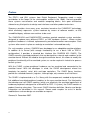
Preface
The PDP11 and VAX systems from Digital Equipment Corporation made a major
contribution to the 'boom' of the minicomputer market in the 1980's. Not only provided
these systems cost-effective and modular computing blocks, their open architecture
allowed many third parties to design new interfaces and other product extensions.
Stromasys provides since many years emulators based on the CHARON™ technology,
which accurately represents system hardware by means of software models, so that
unmodified legacy software can continue to be used.
The CHARON-VAX and CHARON-PDP emulators provide complete system emulation,
designed to replace many different PDP11 or VAX hardware systems. Where custom
peripheral hardware is involved, replacement by emulation becomes more complex. Such
systems often remain in place as redesign or emulation is deemed too costly.
For such complex systems, CHARON was developed as an adaptable emulator platform.
In addition to its kernel (with enough functionality to run a basic VAX or PDP-11
configuration), it provides a standard bus interface (the CHARON API: CHAPI). The
CHAPI connects emulated peripherals that are designed as external code modules to the
emulator kernel. Without the need to change the emulator kernel, this allows to modify the
peripheral functionality of the emulated system, as can be required in industrial or process
control systems.
With the CHAPI, custom peripheral hardware can be emulated and connected to the
emulator kernel. With the developer in mind, the CHAPI development wizard has
templates for parallel, serial, disk and tape controllers. The CHAPI library functions
provide the standard elements (registers, interrupt logic, etc) common to all interfaces.
The CHAPI is implemented as a C++ library with the components needed to dynamically
link additional emulated peripheral modules to the core emulator kernel. For third parties
that develop and sell CHAPI modules (which are effectively the emulated equivalents of
hardware peripherals designed for a MicroVAX or PDP-11 system), the CHAPI contains a
product licensing subsystem. The current CHAPI interface definition, libraries and design
information are described in this manual. Source code samples to assist in device
modifications and new design are available on request.
Geneva,14 December 2007.
x
Summary
CHAPI system components and libraries
− Basic CHAPI interface
− General CHAPI support library
− Serial I/O CHAPI support library
− Parallel I/O CHAPI support library
− Disk/Tape I/O CHAPI support library
− Industrial I/O CHAPI support library
CHAPI based perefpheral devices
− Serial line controllers DHV11, DL11, DZ11, LPV11 printer port.
− Parralel interfaces DRV11, DRV11-WA via HW adapter
− QBUS interface via HW adapters
− Sync serial interface DPV11 via HW adapter
− Industrial DAC/ADC via HW adapter
− Serial line ports (Host COM port, Telnet and E2S mode)
− Exact Real-time line / programmable clocks
CHAPI functional examples (unsupported,provoded in binary form):
− The DHV11/DHU11, DH11, DL11/DLV11 serial adapters
− The DRV11-WA, DR11(C)/DRV11 parallel controllers using the Sensoray 621.
− TSV05/TS11 tape subsystem emulation.
− Emulation of the RL01/RL02 disk controllers.
− LPV11 printer port sample.
− An implementation of the VCB02 video subsystem.
− VT30-H video subsystem
xi
− DPV11 synchronous serial I/O adapter mapped to SEALEVEL-5102S
− MRV11 Universal programmable read-only memory
− IAV1S-AA(IAV1S-C/CA), IAV1S-B industrial ADC/DAC
xii
This manual is for...
This manual assumes familiarity with the setup and installation of the CHARON-VAX or
CHARON-PDP emulators. It is intended for Resellers and end-users who plan to emulate
complex VAX or PDP-11 configurations that might required custom emulator components.
Extending the emulated system environment with custom components or modifying
existing emulated peripheral components with the CHAPI demands significant software
development capabilities. Designing an emulated peripheral requires a thorough
understanding of Qbus or Unibus hardware, bus protocols, peripheral hardware
documentation, C/C++ programming and development experience for the Windows
operating system.
When modifying I/O subsystem emulation to meet protocol or timing requirements, the
appropriate test equipment and software and the separate development / tracing facilities
in CHAPI should be used.
Stromasys can be contacted for the development specific emulator extensions on a
custom project basis.
xiii
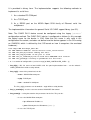
Conventions
The following conventions are used in this manual:
Notation
Description
$ or >
The dollar sign or the right angle bracket in interactive examples
indicates operating system prompt.
User
Input
Bold monospace type in interactive examples indicates typed
user input.
<path>
Bold monospace type enclosed by angle brackets indicates
command parameters and parameter values.
Output
Monospace type in interactive examples indicates the output the
command responds with.
[]
In syntax definitions, brackets indicate items that are optional.
…
In syntax definitions, a horizontal ellipsis indicates that the
preceding item can be repeated one or more times.
xiv
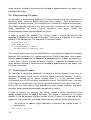
1.CHAPI functionality
1.1 CHAPI overview
CHARON-PDP / CHARON-VAX is a hardware abstraction layer to replace multiple architecturally related - legacy systems. The CHAPI functionality is limited to
QBUS/UNIBUS
An essential part of CHARON-VAX/CHARON-PDP emulators / W32 is the design
environment for the CHARON API (CHAPI) through which additional run-time components
(in the form of Windows DLLs) can be added to the emulated system. This permits to
modify the emulation of existing peripheral emulator components or to design custom
components. Such components can be sold by VARs as product add-ons and licensed via
the CHARON license key.
The CHAPI implementation is optimized for low latency access to the emulator core. This
is important for the replacement of real-time and embedded hardware systems, with
further optimizations possible by modifying device emulation code. To cover a wide range
of possible QBUS/UNIBUS connections, two methods are available:
A set of library components that provide the typical elements in a QBUS/UNIBUS
device: I/O registers, interrupt vectors and DMA. These components are used to
emulate individual bus devices. Both the I/O address space and the memory
address space can be accessed this way.
A more specific set of functions for so called CHARON deep integration, that
permits direct access to the CHARON core modules. Using those functionality
might make Stromasys involvement necessary on a project basis.
CHAPI functions are available to access the CHARON license key number or use the
encrypt/decrypt facility of the key.
Several CHAPI development support libraries are available to assist in the development of
new functions (see further on in this chapter).
1.2 The CHARON CHAPI system components
The included CHAPI modules extend the functionality, but these modules can be replaced
or modified without an impact on the emulator core. Internal components cannot be
modified, but if an equivalent CHAPI component is available, a loadable internal peripheral
emulator component can be removed by not loading it in the configuration file.
15
1.2.1 CHAPI components shared by CHARON-VAX and CHARON-PDP emulators:
CHAPI(D).DLL – general CHAPI support library and its debug version;
CHAPI_DH11.DLL – full functional CHAPI implementation of DH11/DM11 serial
multiplexer with ability to map its ports to: 1) Standard COM port; 2) TCP/IP link; 3) MOXA
NPort 5210 port;
CHAPI_DHV11.DLL – full functional CHAPI implementation of DHV11 serial multiplexer
with ability to map its ports to: 1) Standard COM port; 2) TCP/IP link; 3) MOXA NPort 5210
port;
CHAPI_DLV11.DLL – full functional CHAPI implementation of DLV11 serial controller with
ability to map its port to: 1) Standard COM port; 2) TCP/IP link; 3) MOXA NPort 5210 port;
CHAPI_DPV11.DLL – A CHAPI implementation of synchronous DPV11 adapter.
Appropriate port is implemented in CHAPI_SERIAL.DLL;
CHAPI_DR11.DLL – A CHAPI implementation of DR11(C) /DRV11 parallel interface;
CHAPI_DR11_621_PORT.DLL – A parallel digital IO card port for CHAPI_DR11.DLL
mapped to Sensoray 621 digital IO card;
CHAPI_DRV11WA.DLL – A complete CHAPI implementation of a DRV11-WA parallel I/O
QBUS board based on the TLC DCI-1100 PCI adapter;
CHAPI_DRV11WA_621.DLL – A complete CHAPI implementation of a DRV11-WA
parallel I/O QBUS board based on the Sensoray 620 digital IO card;
CHAPI_DRV11WA_621_PORT.DLL – A parallel digital IO card port
CHAPI_DRV11WA_621.DLL mapped to the Sensoray 621 digital IO card;
for
the
CHAPI_HTIME.DLL – A special CHAPI device to get host system time from RSX11
system; The HTIM.TSK RSX11 task is distributed with this device far a complete solution;
CHAPI_HW(D).DLL – Hardware substitution library and its debug version;
CHAPI_MRV11.DLL – Universal programmable read-only memory device.
CHAPI_IAV1S_AA.DLL - full functional CHAPI implementation for QBUS IAV1S-AA/C/CA
industrial DAC. It uses CHAPI industrial IO library CHAPI_INDIO.DLL
CHAPI_IAV1S_B.DLL - full functional CHAPI implementation for QBUS IAV1S-D industrial
DAC. It uses CHAPI industrial IO library CHAPI_INDIO.DLL
CHAPI_PARALLEL(D).DLL – Parallel I/O CHAPI support library and its debug version;
16
CHAPI_QBUS.DLL – CHAPI implementation of bus adapter link to external QBUS cage
using BCI-2104 bus adapter;
CHAPI_S3QBUS.DLL – CHAPI implementation of bus adapter link to external QBUS cage
using CESYS PCIS3BASE bus adapter;
CHAPI_RLV12.DLL – full functional CHAPI implementation for UNIBUS RL11 / QBUS
RLV12 disk controllers supporting RL01/RL02 disk drives; It is possible to map mentioned
controllers’ disk units to the disk image container or to raw physical disk drive via windows
driver container– these containers are implemented within the “Storage CHAPI support”
library;
CHAPI_INDIO.DLL – industrial I/O CHAPI support library; It supports industrial ADC/DAC
mapped to SENSORAY Ethernet board model 2601/2608;
CHAPI_SERIAL(D).DLL – serial I/O CHAPI support library and its debug version; It
support three different kind of ports: 1) Standard COM port; 2) TCP/IP link; 3) MOXA
NPort 5210 port; All these ports can be used from any new CHAPI serial line multiplexer
developed in accordance with the “Serial I/O CHAPI support” library rules;
This library contains addition ‘seasync’ port implemented. This port can be used only with
CHAPI_DPV11 device implementation;
CHAPI_STORAGE(D).DLL – “Storage I/O CHAPI support” library and its debug version; It
provides three tape containers which can be easily reused in newly created tape
controllers to map there units to: 1) Tape image file in MTD format; 2) SCSI tape
connected to the system; 3) Windows tape driver supported hardware tape like \\.\TapeK
connected to the system. Two disk containers are provided for the moment in this library –
Disk image file and raw physical disk drive via windows driver supported hardware disks
like \\.\PhysicalDrive0 connected to the system.
CHAPI_TSV05.DLL – full functional CHAPI implementation for QBUS TSV11/TSV05 and
UNIBUS TS11 tape controllers; It allows to map tape unit to one of selected containers
provided by means of “Storage I/O CHAPI support” library: 1) Tape image file in MTD
format; 2) SCSI tape connected to the system; 3) Windows tape driver supported
hardware tape like \\.\TapeK connected to the system;
CHAPI_UNIBUS - CHAPI implementation of bus adapter link to external UNIBUS cage
using BCI-2004 bus adapter;
CHAPI_VCB02.DLL – A CHAPI implementation of the VCB02 video subsystem;
CHAPI_VT30H.DLL --- full functional CHAPI implementation for QBUS/UNIBUS VT30-H
graphics display controller.
LPV11.DLL – The CHAPI implementation of the LPV11 parallel port controller;
17
1.2.2 CHAPI Development libraries
CHAPI.LIB – The library to link with in case the components described in the
CHAPI_LIB.H header file are used for a particular CHAPI module implementation; it
should be used in a release build of a CHAPI device;
CHAPID.LIB – The debug version of the CHAPI.LIB library; it should be used in a debug
build of a CHAPI device;
CHAPI_SERIAL.LIB – The library to link with in case the base classes for a serial line
controller/port implementation are used for a particular CHAPI module implementation; it
should be used in a release build of the CHAPI device;
CHAPI_SERIALD.LIB – The debug version of CHAPI_SERIAL.LIB; it should be used in a
debug build of a CHAPI device;
CHAPI_PARALLEL.LIB – The library to link with in case the base classes for a parallel
controller/port implementation are used for a particular CHAPI module implementation; it
should be used in a release build of the CHAPI device;
CHAPI_SERIALD.LIB – The debug version of CHAPI_PARALLEL.LIB; it should be used
in a debug build of a CHAPI device;
CHAPI_STORAGE.LIB - The library to link with in case the base classes for a disk/tape
controller/unit implementation are used for a particular CHAPI module implementation; it
should be used in a release build of a CHAPI device;
CHAPI_STORAGED.LIB – The debug version of CHAPI_STORAGE.LIB; it should be
used in a debug build of a CHAPI device;
1.2.3 The CHARON drivers used by CHAPI modules
These drivers are provided 'as is':
BCI2X0X.SYS – The BCI-2104/BCI-2004 bus adapter driver used by the
CHAPI_QBUS and CHAPI_UNIBUS examples. This is a proof of concept as the
BCI-2x04 products are end of life.
S3QBUS_PPT.SYS – The S3QBUS (based on the CESYS PCIS3BASE board) bus
adapter driver used by the CHAPI_S3QBUS.
DCI1100.SYS – The DCI-1100 adapter driver used by the CHAPI_DRV11WA
example. This is a proof of concept as the DCI-1100 is end of life.
PPT.SYS – A generic PCI 'Pass-through' device driver that is used for
CHAPI_DR11©/DRV11, CHAPI_DRV11-WA ports mapped to a Sensoray 621
18
digital I/O board and CHAPI_DPV11 mapped to SEALEVEL SYNC SERIAL
BOARD 5102S board.
1.3 The CHAPI CHARON utilities
1.3.1 The CHARON CHAPI device creation wizard
The CHAPI device creation wizard is designed to simplify the creation of a CHAPI device:
it is a sequence of GUI dialogs that leads the designer to a Visual Studio C++ project. The
following features are supported:
-
Project type selection (General CHAPI device, Serial I/O multiplexer / Port, Disk
controller / container, Tape controller / Container, CHAPI Bus / Bus adapter, PCI
replacement hardware based controller / adapter, etc…)
-
Selection of the required parameters using GUI dialogs related to the selected
project type;
-
Generation of Visual Studio C++ project files and parameters for the component
under design. The generated project is buildable and satisfies the requirements for
selected type of CHAPI device and the CHAPI support libraries;
1.3.2 HOSTprint
This utility prints data supplied by the emulated printer ports (CHAPI LPV11) of PDP11/VAX systems using specified host system printer through a TCP/IP socket (see
example of device which uses HOSTprint).
1.4 CHARON-PDP and CHARON-VAX with CHAPI support.
In CHARON the interface (CHAPI) to peripheral components behaves as a software
replica of the QBUS bus.
The CHAPI standard facilitates the design, modification and exchange of emulated
peripheral devices without requiring a change in the emulator kernel. This opens the way
for third parties to adapt the emulator to specific needs, for instance to add the emulation
of a custom peripheral by building a software replica of the original module.
CHARON emulators with CHAPI is both a production emulator and a test and
development environment for functionality extensions. It includes a design environment,
which supports the replacement, modification, design and test of new components. Most
library functions in the design environment are provided in both a debug and a release
version, and templates for specific device types support rapid development. The CHAPI
can access the CHARON/VAX or CHARON-PDP license key and use its encryption
capabilities for licensing such external components.
19
1.5 CHAPI based components provided with CHARON-VAX or
CHARON-PDP.
CHARON kits contains a number of CHAPI based components that are provided on an
'as is' basis. Some of these components are provided in source code to help a developer
to modify or create new CHAPI based devices. The supplied examples are chosen to
reflect the aspects of general device using CHAPI, they do not necessarily suggest an
optimal implementation for a specific project.
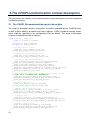
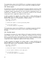
1.5.1 Loading the CHAPI components
Any CHAPI component created in accordance with the CHAPI specification is represented
by a dynamically linked library (DLL). Such a component is loaded with the emulator
kernel by specifying it - with an arbitrary logical name - in the configuration file. Each such
DLL can have its parameters set using the standard set command syntax:
// Load a user created CHAPI device, implemented as chapi_dev.dll
// Identified as <dev_name>, specify its bus address,
// interrupt vector and user defined parameters.
load chapi <dev_name> dll = chapi_dev.dll
set <dev_name> address = <device_bus_address>
set <dev_name> vector = <device_interrupt_vector>
set <dev_name> trace_level = <trace_level>
set <dev_name> par1[N]=val1 par2[N]=val2 … parK[N] = valK
Parameters ‘address’, ‘vector’ and ‘trace_level’ are common for any kind of CHAPI bus
device. The implementation specific parameters can be passed to the CHAPI device in
two different ways:
1) By means of a single string parameter called ‘parameter’ – this method, used in the
first implementation of CHAPI is only retained for compatibility reasons and not
recommended. The CHAPI examples in this manual do not use this method.
2)
By specifying a 'set' command for any of the user defined configuration parameters
created during the CHAPI device initialization. These configuration options are
specified in the following lines of the configuration file, after the ‘dll’ load command
has associated the device with its given logical name '<dev_name>'.
The details of the CHAPI API, and how to use user defined configuration options are
described later in this document. Usage examples are also supplied.
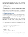
1.5.2 The CHAPI device list
DH11
The CHAPI DH11 UNIBUS serial line multiplexer is implemented as the
CHAPI_DH11.DLL and uses CHAPI_SERIAL.DLL and CHAPI.DLL for its implementation.
20
It is provided in binary form. The implementation supports the following methods to
implement its serial lines:
1. As a standard PC COM port
2. As a TCP/IP port;
3. As a RS232 port on the MOXA Nport 5210 family of Ethernet serial line
multiplexers.
The implementation is based on the general Serial I/O CHAPI support library (see 5.2).
Note: The CHAPI DH11 device cannot be configured using the legacy ‘parameter’
configuration method. The CHAPI DH11 device is configured as follows (in this example
the logical name for the device is YHA. Note that this name is only valid in this
configuration file context, and does not define how the device appears in the OS running
on CHARON, which is defined by that OS based on how it recognizes the emulated
hardware):
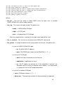
load chapi YHA dll=chapi_dh11.dll
set YHA address=<address> vector=<vector> trace_level=<level>
set YHA line_dll[x]=<serial library dll file>
set YHA line_cfg[x]=<name of the port to load>
set YHA line_is_terminal[x]=<do we need force XON/XOFF flow control>
set YHA line_param[x]=”<string of parameters for the line>”
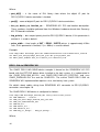
• x – is a number of configured line ( can be in range [0, MAX_CONTROLLER_LINES - 1] )
• line_dll[x] – DLL file name to load CHAPI serial line port implementation from – can be omitted –
CHAPI_SERIAL.DLL will be used by default;
• line_cfg[x] – name of the port to load, can be:
• moxa – MOXA NPort 5210 port
• tcpip –TCP/IP port
• com – standard PC COM port
The 'line_cfg[x]' parameter can be omitted – 'tcpip' will be used by default;
• line_is_terminal[x] – must be set to true to force XON/XOFF flow control
• line_param[x] – a string that contains the parameters for the line. They can be:
• In case of a MOXA NPort 5210 port:
• ip=<NPort5210 IP address>;
• port=<RS232 port of a NPort5210>, (1, 2, …);
• In case of a TCP/IP port:
21
• port=<IP port for connection to or listen to>;
• application=”<application to start>”;
• ip=<IP address to connect to>. If this parameter is present, the line will try to connect
to this IP address. If this parameter is not present, the line will accept connections
• In case of a standard COM port:
• com=<COM port number>, (1, 2, …)
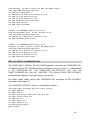
Example:
load chapi YHA dll=chapi_dh11.dll
set YHA address= 017760020 vector=0310 trace_level=0
#LINE[0] IS SERVER
set YHA line_dll[0]=chapi_serial line_cfg[0]=tcpip
set YHA line_is_terminal[0]=true line_param[0]="port=10020 application=txa0.ht"
set YHA line_dll[1]=chapi_serial line_cfg[1]=com
set YHA line_is_terminal[1]=true line_param[1]="com=1"
set YHA line_dll[2]=chapi_serial line_cfg[2]=moxa
set YHA line_is_terminal[2]=true line_param[2]="ip=192.168.127.254 port=1"
set YHA line_dll[3]=chapi_serial line_cfg[3]=moxa
set YHA line_param[3]="ip=192.168.127.254 port=2"
#LINE[4] IS CLIENT
set YHA line_dll[4]=chapi_serial line_cfg[4]=tcpip
set TXA line_param[4]="ip=192.168.1.1 port=10055"
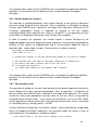
DHV11
The CHAPI DHV11 QBUS serial line multiplexer is implemented as the
CHAPI_DHV11.DLL and uses CHAPI_SERIAL.DLL and CHAPI.DLL for its
implementation. It is provided in binary form. The implementation supports the following
methods to implement its serial lines:
1. As a standard PC COM port
2. As a TCP/IP port;
3. As a RS232 port on the MOXA Nport 5210 family of Ethernet serial line
multiplexers.
The implementation is based on the general Serial I/O CHAPI support library (see 5.2).
22
Note: The CHAPI DHV11 device cannot be configured using the legacy ‘parameter’
configuration method. The CHAPI DHV11 device is configured as follows (in this example
the logical name for the device is TXA. Note that this name is only valid in this
configuration file context, and does not define how the device appears in the OS running
on CHARON, which is defined by that OS based on how it recognizes the emulated
hardware):
load chapi TXA dll=chapi_dhv11.dll
set TXA address=<address> vector=<vector> trace_level=<level>
set TXA line_dll[x]=<serial library dll file>
set TXA line_cfg[x]=<name of the port to load>
set TXA line_is_terminal[x]=<do we need force XON/XOFF flow control>
set TXA line_param[x]=”<string of parameters for the line>”
Where :
• x – is a number of configured line ( can be in range [0, MAX_CONTROLLER_LINES - 1] )
• line_dll[x] – DLL file name to load CHAPI serial line port implementation from – can be omitted –
CHAPI_SERIAL.DLL will be used by default;
• line_cfg[x] – name of the port to load, can be:
• moxa – MOXA NPort 5210 port
• tcpip –TCP/IP port
• com – standard PC COM port
The 'line_cfg[x]' parameter can be omitted – 'tcpip' will be used by default;
• line_is_terminal[x] – must be set to true to force XON/XOFF flow control
• line_param[x] – a string that contains the parameters for the line. They can be:
• In case of a MOXA NPort 5210 port:
• ip=<NPort5210 IP address>;
• port=<RS232 port of a NPort5210>, (1, 2, …);
• In case of a TCP/IP port:
• port=<IP port for connection to or listen to>;
• application=”<application to start>”;
• ip=<IP address to connect to>. If this parameter is present, the line will try to connect
to this IP address. If this parameter is not present, the line will accept connections
• In case of a standard COM port:
• com=<COM port number>, (1, 2, …)
23
Example:
load chapi TXA dll=chapi_dhv11.dll
set TXA address=017760520 vector=0340 trace_level=1
#LINE[0] IS SERVER
set TXA line_dll[0]=chapi_serial line_cfg[0]=tcpip
set TXA line_is_terminal[0]=true line_param[0]="port=10020 application=txa0.ht"
set TXA line_dll[1]=chapi_serial line_cfg[1]=com
set TXA line_is_terminal[1]=true line_param[1]="com=1"
set TXA line_dll[2]=chapi_serial line_cfg[2]=moxa
set TXA line_is_terminal[2]=true line_param[2]="ip=192.168.127.254 port=1"
set TXA line_dll[3]=chapi_serial line_cfg[3]=moxa
set TXA line_param[3]="ip=192.168.127.254 port=2"
#LINE[4] IS CLIENT
set TXA line_dll[4]=chapi_serial line_cfg[4]=tcpip
set TXA line_param[4]="ip=192.168.1.1 port=10055"
DLV11
The CHAPI DLV11 QBUS / DL11 UNIBUS devices are implemented with
CHAPI_DLV11.DLL and use CHAPI_SERIAL.DLL and CHAPI.DLL for its implementation.
The DLL is available in both binary and source code (source code is listed in document
#30-09-06). This implementation can map its line to:
1. A standard PC COM port;
2. A TCP/IP port;
3. A port on a MOXA Nport 5210 family Ethernet serial line multiplexer.
The DL(V)11 is implemented using the serial I/O CHAPI support library (see 5.2).
This device cannot be configured using the legacy ‘parameter’ configuration method. The
configuration options are as follows:
load chapi TT1 dll=chapi_dlv11.dll
set TT1 address=<address> vector=<vector> trace_level=<level>
set TT1 line_dll=<serial library dll file>
set TT1 line_cfg=<name of the port to load>
set TT1 line_is_terminal=<do we need force XON/XOFF flow control>
set TT1 line_param=”<string of parameters for the line>”
set TT1 baud_rate=<preselected baud rate of the line>
set TT1 baudselen=<must be true to enable program baud rate selection>
set TT1 dtr=<must be true to force set DTR signal ON>
24
set
set
set
set
set
set
set
TT1
TT1
TT1
TT1
TT1
TT1
TT1
rts=<must be true to force set RTS signal ON>
mode=”<DLV11-E or DLV11-F>”
breaken=<must be true to enable break signal generation>
erroren=<must be true to enable RX error notification>
char_len=<character’s bit length>
stop_len=<stop bit length>
parity=”<parity control>”
Where :
• line_dll – The DLL file name to load CHAPI serial line port from. If omitted
CHAPI_SERIAL.DLL will be used by default;
• line_cfg – The name of the port to load. The options are:
• moxa – a MOXA NPort 5210 port
• tcpip – a TCP/IP port
• com – a standard host PC COM port
If the line_cfg parameter is omitted, the the port name tcpip will be used.
• line_is_terminal – This must be set to true to force XON/XOFF flow control
• line_param – A string that contains the line parameters for the line. The options are:
• In case of a MOXA NPort 5210 port:
• ip= the NPort 5210 IP address;
• port= The RS232 port number on the NPort5210, (1, 2, …);
• In case of a TCP/IP port:
• port=The IP port to connect to or to listen to;
• application=”<application to start>”;
• ip= The IP address to connect to. If this parameter is present, the
emulated serial line will try to connect to this address. If this parameter
is not present, the line will accept connections.
• In case of a standard COM port:
• com=<COM port number>, (1, 2, …)
• baud_rate – The baud rate at which the communication line operates.
25
• baudselen – must be true to enable OS baud rate selection
• dtr – must be true to force the DTR signal to ON.
• rts – must be true to force the RTS signal to ON.
• mode – Either ‘E’ or ‘F’ to select DLV11-E or DLV11-F functionality.
• breaken – must be true to enable break generation
• erroren – must be true to enable RX error notification
• char_len – the byte length of transmitted and received characters.
• stop_len – the number of stop bits to be used
• parity – Parity control: “none”, “even”, “odd”, “mark” or “space”
Examples:
# DLV11-E connected to COM port
load chapi TT1 dll=chapi_dlv11.dll
set TT1 address=017760010 vector=0310 trace_level=1
set TT1 line_dll=chapi_serial
set TT1 line_cfg=com
set TT1 line_is_terminal=true
set TT1 line_param=”com=1”
set TT1 baud_rate=9600
set TT1 baudselen=true
set TT1 dtr=true
set TT1 rts=true
set TT1 mode=”e”
set TT1 breaken=true
set TT1 erroren=true
set TT1 char_len=8
set TT1 stop_len=1
set TT1 parity=”none”
# DLV11-E connected to a MOXA NPort 5210, RS232 port 2
load chapi TT1 dll=chapi_dlv11.dll
set TT1 address=017760010 vector=0310 trace_level=1
set TT1 line_dll=chapi_serial
set TT1 line_cfg=moxa
set TT1 line_is_terminal=true
set TT1 line_param=”ip=192.168.127.254 port=2”
set TT1 baud_rate=9600
set TT1 baudselen=true
set TT1 dtr=true
set TT1 rts=true
set TT1 mode=”e”
set TT1 breaken=true
26
set
set
set
set
TT1
TT1
TT1
TT1
erroren=true
char_len=8
stop_len=1
parity=”none”
# DLV11-E connected to TCPIP, line is server
load chapi TT1 dll=chapi_dlv11.dll
set TT1 address=017760010 vector=0310 trace_level=1
set TT1 line_dll=chapi_serial
set TT1 line_cfg=tcpip
set TT1 line_is_terminal=true
set TT1 line_param=”port=10020 application=term.ht”
set TT1 mode=”e”
# DLV11-E connected to TCPIP, line is client
load chapi TT1 dll=chapi_dlv11.dll
set TT1 address=017760010 vector=0310 trace_level=1
set TT1 line_dll=chapi_serial
set TT1 line_cfg=tcpip
set TT1 line_is_terminal=true
set TT1 line_param=”ip=192.168.1.1 port=10020”
set TT1 mode=”e”
DPV11
The CHAPI DPV11 QBUS devices are implemented with CHAPI_DPV11.DLL and use
CHAPI_SERIAL.DLL and CHAPI.DLL for its implementation. The DLL is available in
binary only. This implementation can map its line to SEALEVEL SYNC SERIAL BOARD
5102S port.
This device cannot be configured using the legacy ‘parameter’ configuration method. The
configuration options are as follows:
load chapi UF1 dll=chapi_dpv11.dll
set UF1 address=<address> vector=<vector> trace_level=<level>
set UF1 line_dll=<serial library dll file>
set UF1 line_cfg=<name of the port to load>
set UF1 bus_no=<SEALEVEL 5102S PCI bus number>
set UF1 device_no=<SEALEVEL 5102S PCI device number>
set UF1 function_no=<SEALEVEL 5102S PCI function number>
set UF1 rx_clock_direction=<RX sync clock source definition>
set UF1 tx_clock_direction=<TX sync clock source definition>
set UF1 interface_mode=<sync serial interface mode>
set UF1 clock_rate=<desired clock rate (for output clock direction)>
Where :
27
• line_dll – The DLL file name to load CHAPI serial line port from, must be chapi_serial only.
If omitted CHAPI_SERIAL.DLL will be used by default;
• trace_level – Debug trace level (0 - 10), 0 for NO traces or 10 for MAX traces. If omitted zero will
be used by default;
• line_cfg – The name of the port to load. Must be:
• seasync – a SEALEVEL PCI 5102S board port
If the line_cfg parameter is omitted, the port name seasync will be used.
• bus_no - SEALEVEL 5102 PCI bus number. If omitted zero will be used by default;
• device_no - SEALEVEL 5102 PCI device number. If omitted zero will be used by default;
• function_no - SEALEVEL 5102 PCI function number. If omitted zero will be used by default;
• rx_clock_direction/tx_clock_direction - Definitions of clock source for transmitting
and receiving. Use IN if you want SEALEVEL 5102S to accept external clock. Use OUT
if you want SEALEVEL 5102S to provide internal clock. If omitted IN will be used by
default;
• interface_mode – SEALEVEL 5102S interface mode. Can be:
• none – all pins are in high impedance;
• rs232 – for SYNC RS-232 interface;
• rs530_422 – for SYNC RS-530(422) interface;
• rs530a – for SYNC RS-530A interface;
• v35 – for V.35 interface;
If omitted NONE will be used by default;
• clock_rate - desired clock rate (300baud – 128KBaud) if OUT direction is selected. If
omitted 9600 will be used by default;
For information about SEALEVEL PCI 5102S sync serial board connector’s pins
definition please refer to its manual (www.sealevel.com).
Examples:
# DPV11, use SEALEVEL 5102S at PCI 1/7/0,
28
# RS-422(530), provide clock at 2.4 kHz, NO debug traces
load chapi UFA dll=chapi_dpv11.dll
set UFA line_cfg=seasync
set UFA bus_no=1 device_no=7 function_no=0
set UFA tx_clock_direction="out"
set UFA rx_clock_direction="out"
set UFA interface_mode="rs530_422"
set UFA trace_level=0
set UFA clock_rate=2400
# DPV11, use SEALEVEL 5102S at PCI 1/7/0,
# RS-232,NO debug traces, accept external clock
load chapi UFA dll=chapi_dpv11.dll
set UFA bus_no=1 device_no=7 function_no=0
set UFA interface_mode="rs232"
# DPV11, use SEALEVEL 5102S at PCI 1/7/0,
# RS-232, provide clock at 9.6 kHz, NO debug traces
load chapi UFA dll=chapi_dpv11.dll
set UFA bus_no=1 device_no=7 function_no=0
set UFA tx_clock_direction="out"
set UFA rx_clock_direction="out"
set UFA interface_mode="rs232"
DR11(C) / DRV11 via SENSORAY 621
The CHAPI DRV11 QBUS or DR11(C) UNIBUS device is based on the SENSORAY 621
PCI board, with the PPT.SYS device driver installed in the host system. It is implemented
in the CHAPI_DR11.DLL and CHAPI_DR11_621_PORT.DLL and uses the
CHAPI_PARALLEL.DLL and the CHAPI.DLL. The current CHAPI DR11(C)/DRV11
implementation requires a fast, low-latency host system.
For details about cables wiring from SENSORAY 621 connector to DR11(C)/DRV11
connectors see chapter 9.
The CHAPI DR11(C)/DRV11 device is configured as follows:
load chapi DR11 dll=chapi_dr11.dll trace_level=0
set DR11 address=...
set DR11 vector=...
set DR11 port_dll[0]= chapi_dr11_621_port.dll
set DR11 port[0]= dr11_621
set DR11 bus_no=...
set DR11 device_no=...
set DR11 function_no=...
set DR11 brq_priority=...
pulse_width=...
29
Where:
• port_dll[0] – is the name of DLL library from where the digital IO port for
DR11(C)/DRV11 device emulation is loaded;
• port[0] – name of digital IO port for DR11(C)/DRV11 device emulation;
• bus_no, device_no, function_no - SENSORAY 621 PCI card location description.
These numbers should be gathered from the Windows hardware wizard after Sensoray
621 PCI board installation.
• brq_priority – bus request priority level for DR11(C)/DRV11 device, If this parameter is
omitted, 4 is used as default
• pulse_width – time length of INIT / READ / WRITE pulses in approximately 450ns
units, If this parameter is omitted, 2 (i.e. 900ns) is used as default
Example:
load chapi DR11 dll=chapi_dr11.dll address=017767770 vector=0300 trace_level=0
set DR11 port_dll[0]=chapi_dr11_621_port.dll port[0]=dr11_621
set DR11 pulse_width=1 bus_no=1 device_no=7 function_no=0
DRV11-WA via SENSORAY 621
The CHAPI DRV11-WA QBUS device example is based on the SENSORAY 621 PCI
board, with the PPT.SYS device driver installed in the host system. It is implemented in
the CHAPI_DRV11WA_621.DLL and CHAPI_DRV11WA_621_PORT.DLL and uses
CHAPI_PARALLEL.DLL the and the CHAPI.DLL. The current CHAPI DRV11-WA via
SENSORAY 621 implementation requires a fast, low-latency host system.
For details about cables wiring from SENSORAY 621 connector to DR11(C)/DRV11
connectors see chapter 10.
The CHAPI DRV11-WA device is configured as follows:
load chapi IXA dll=chapi_drv11wa_621 trace_level=<trace_level>
set IXA address=... vector=...
set IXA port_dll= chapi_drv11wa_621_port.dll
set IXA port_name=drv11wa_621
set IXA bus_no=...
set IXA device_no=...
set IXA function_no=...
set IXA busy_lo_delay=... busy_hi_delay=...
Where,
30
• port_dll – is the name of DLL library from where the DRV11-WA device emulation is
loaded. If this parameter is omitted, CHAPI_DRV11WA_621_PORT.DLL is used as
default;
• port_name – the name of DRV-11WA replacement adapter connection module to load
from the specified DLL library. If this parameter is omitted, 'drv11wa_621' will be used
as default;
• bus_no, device_no, function_no - SENSORAY 621 PCI card location description.
These numbers should be gathered from the Windows hardware wizard after Sensoray
621 PCI board installation.
• busy_lo_delay - BUSY signal delay in LOW level in approximately 450ns units. If this
parameter is omitted, 0 is used as default
• busy_hi_delay - BUSY signal delay in HIGH level in approximately 450ns units. If this
parameter is omitted, 0 is used as default
Example:
load chapi IXA dll=chapi_drv11wa_621.dll trace_level=0
set IXA bus_no=1 device_no=7 function_no=0
set IXA busy_lo_delay=0 busy_hi_delay=0
DRV11-WA
The CHAPI DRV11-WA QBUS device example is based on the DCI-1100 PCI board from
The Logical Company, with the DCI1100.SYS device driver installed in the host system. It
is implemented in the CHAPI_DRV11WA.DLL (in binary form) and uses the
CHAPI_HW.DLL and the CHAPI.DLL. Note that the DCI-1100 is end of life as it does not
meet the RoHS environmental requirements. The current CHAPI DRV11-WA
implementation requires a fast, low-latency host system and is only provided as an
example, instability has been observed in some test configurations. It is recommended to
develop a custom parallel I/O CHAPI device with the appropriate host interface for a
specific project.
The CHAPI DRV11-WA device is configured as follows:
load chapi IXA dll=chapi_drv11wa trace_level=<trace_level>
set IXA address=... vector=...
set IXA adapter_dll=chapi_hw
set IXA adapter_name=dci1100
set IXA adapter_instance=0
set IXA adapter_options=""
Where,
31
• adapter_dll – is the name of DLL library from where the DRV11-WA device emulation is
loaded. If this parameter is omitted, chapi_hw.DLL is used as default;
• adapter_name – the name of DRV-11WA replacement adapter connection module to
load from the specified DLL library. If this parameter is omitted, 'dci1100' will be used as
default;
• adapter_instance – This is the instance number of the DRV11-WA replacement
adapter to use, in case a number of the specified replacement adapters are installed on
the PCI bus. If this parameter is omitted, 0 (i.e. The first instance) is used as default.
• adapter_options – any optional device parameters to be passed to the DRV11-WA
replacement adapter connection module. No options are defined for dci1100 adapter
implemented in the chapi_hw DLL library. If this parameter is omitted, an empty string is
default;
HTIME
The CHAPI HTIME QBUS/UNIBUS device is a custom CHAPI implementation to obtain
the host system date and time. It is implemented in the CHAPI_HTIME.DLL and uses the
CHAPI.DLL. The device is provided in binary form; it is essentially designed to copy the
host system time to the RSX11 system time, in combination with the RSX-11 HTIM task.
Details are provided in (FIXME: add reference here).
The CHAPI HTIME device has no options and is configured as follows:
load chapi host_time dll=chapi_htime trace_level=<trace_level>
IAV1S-AA, IAV1S-C / IAV1S-CA
The CHAPI IAV1S-AA QBUS devices are implemented with CHAPI_IAV1S_AA.DLL and
use CHAPI_INDIO.DLL and CHAPI.DLL for its implementation. The DLL is available in
binary only. This implementation can map its ADC lines to SENSORAY 2601, 2608
ADC/DAC Ethernet boards.
This device cannot be configured using the legacy ‘parameter’ configuration method.
The configuration options are as follows:
load chapi ADC dll=chapi_iav1s_aa.dll address=<> vector=<>
set ADC trace_level=<trace_level>
set ADC port_dll=”<port_dll>”
set ADC port_cfg=”<port_cfg>”
set ADC port_param[x]="<IP address>"
set ADC port_offset[x]=<adc_offset>
set ADC bipolar=<bipolar>
32
Where :
• port_dll – The DLL file name to load CHAPI ADC port from. If omitted
CHAPI_INDIO.DLL will be used by default;
• trace_level – Debug trace level (0 - 10), 0 for NO traces or 10 for MAX traces. If omitted
zero will be used by default;
• port_cfg – The name of the port to load. Can be:
• 2600 – a SENSORAY 2601/2608 Ethernet ADC/DAC board port
If the port_cfg parameter is omitted, the port name “2600” will be used.
• port_param[x] – IP address of SENSORAY 2601 board (where desired SENSORAY 2608 is
connected) where group <x> of 16 ADC channels (situated on the IAV1S-AA / IAV1S-C / IAV1S-CA
devices) is to be mapped to, this parameter must not be omitted:
-
x = 0 for group of 16 ADC channels situated on the IAV1S-AA board;
- x > 0 for group of 16 ADC channels situated on the IAV1S-C/IAV1S-CA MUX boards;
• port_offset[x] – offset for group of 16 ADC (situated on the IAV1S-AA / IAV1S-C / IAV1S-CA devices)
on the SENSORAY 2601 board (selected by port_param[x]) to select desired SENSORAY 2608 board, this
parameter must not be omitted:
-
x = 0 for group of 16 ADC channels situated on the IAV1S-AA board;
- x > 0 for group of 16 ADC channels situated on the IAV1S-C/IAV1S-CA MUX boards;
• bipolar – set to TRUE for bipolar ADC. If omitted unipolar ADC will be used by default
For information about any technical information about SENSORAY 2601/2608
Ethernet boards please refer to its manual (www.sensoray.com).
Examples:
#load IAV1S-AA with one MUX boards
#two SENSORAY 2608 is connected to 2601 with IP 10.10.10.2
load chapi ADC1 dll=chapi_iav1s_aa.dll address=017761040 vector=0300
set ADC1 port_param[0]="10.10.10.2" port_offset[0]=0
#connect IAV1S-C/IAV1S-CA MUX
set ADC1 port_param[3]="10.10.10.2" port_offset[3]=16
#load IAV1S-AA without any MUX boards
#four SENSORAY 2608 is connected to 2601 with IP 10.10.10.2
#we will use the third 2608 board
load chapi ADC2 dll=chapi_iav1s_aa.dll address=017761050 vector=0320
set ADC2 bipolar=true
set ADC2 port_param[0]="10.10.10.2" port_offset[0]=32
33
IAV1S-B
The CHAPI IAV1S-B QBUS devices are implemented with CHAPI_IAV1S_B.DLL and use
CHAPI_INDIO.DLL and CHAPI.DLL for its implementation. The DLL is available in binary
only. This implementation can map its DAC lines to SENSORAY 2601, 2608 ADC/DAC
Ethernet boards.
This device cannot be configured using the legacy ‘parameter’ configuration method.
The configuration options are as follows:
load chapi DAC dll=chapi_iav1s_b.dll address=<>
set DAC trace_level=<trace_level>
set DAC port_dll=”<port_dll>”
set DAC port_cfg=”<port_cfg>”
set DAC port_param[0]="<IP address>"
set DAC port_offset[0]=<adc_offset>
Where :
• port_dll – The DLL file name to load CHAPI DAC port from. If omitted
CHAPI_INDIO.DLL will be used by default;
• trace_level – Debug trace level (0 - 10), 0 for NO traces or 10 for MAX traces. If omitted
zero will be used by default;
• port_cfg – The name of the port to load. Can be:
• 2600 – a SENSORAY 2601/2608 Ethernet ADC/DAC board port
If the port_cfg parameter is omitted, the port name “2600” will be used.
• port_param[0] – IP address of SENSORAY 2601 board (where desired SENSORAY 2608 is
connected) where group of 4 DAC channels (situated on the IAV1S-B device) is to be mapped to, this
parameter must not be omitted;
• port_offset[0] – offset for group of 8 DAC (situated on the IAV1S-B device) on the SENSORAY 2601
board (selected by port_param[0]) to select desired SENSORAY 2608 board, this parameter must not be
omitted:
For information about any technical information about SENSORAY 2601/2608
Ethernet boards please refer to its manual (www.sensoray.com).
Examples:
#load IAV1S-B
#two SENSORAY 2608 is connected to 2601 with IP 10.10.10.2
load chapi DAC dll=chapi_iav1s_b.dll address=017761060 trace_level=0
34
set DAC port_param[0]="10.10.10.2" port_offset[0]=8
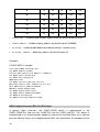
MRV11
The CHAPI MRV11 QBUS/UNIBUS device are implemented with CHAPI_MRV11.DLL
and use CHAPI.DLL for its implementation. MRV11 is universal programmable read-only
memory.
The CHAPI MRV11 device is configured as follows:
load chapi MRVA dll=chapi_mrv trace_level=<trace_level>
set MRVA address=<device_address>
set MRVA chips_installed=<numer of chips installed on board>
set MRVA chip_capacity=<capacity measured>
set MRVA rom_file_name=<rom data file name>
set MRVA direct_mode=<enable/disable direct maping mode>
set MRVA direct_address=<direct maping address>
set MRVA window_mode=<enable/disable windows maping mode>
set MRVA window_address=<windows maping address>
set MRVA bootstrap=<enable/disable bootstrap mode>
set MRVA bootstrap_address=<bootstrap address>
Where:
•
– number of chips installed on board. This parameter must be
multiply of powers of two and must be placed in segment from 1 to 32 (see MRV11
table).
•
– capacity meshured of one chip in bytes. This parameter must be
multiply of powers of two and must be placed in segment from 1 to 32 (see MRV11
table).
•
rom_file_name
•
direct_mode
•
direct_address
chips_installed
chip_capacity
– name of file which contain rom data.
– enable/disable direct maping mode (by default is enable (true)).
– direct maping address (by default equals 0).
Number of Chips
Installed
Capacity Meshured (in Kbytes)
2
4
8
16
32
2
4
8
16
32
64
4
8
16
32
64
128
35
6
12
24
48
96
196
8
16
32
64
128
256
10
20
40
80
160
320
12
24
48
96
192
384
14
28
56
112
224
448
16
32
64
128
256
512
– enable/disable window maping mode (by default disable (false)).
•
window_mode
•
window_address
•
bootstrap
•
bootstrap _address
– window maping_address (by default equals 0160000).
– enable/disable bootstrap mode (by default is enable (true)).
– bootstrap_address (by default equals 0).
Examples:
# CHAPI MRV11 example
load chapi MRVA dll=chapi_mrv
set MRVA address=177000
# Total ROM capacity 6*2 KBytes = 12KBytes
set MRVA chips_installed=6
set MRVA chip_capacity=2
#ROM data file
set MRVA rom_file_name=”my_rom.rom”
#Diaseble direct mode, address do not use
#set MRVA direct_address=020000
#Enable window maping mode
set MRVA window_mode= false
set MRVA window_address=0160000
set MRVA bootstrap=true
set MRVA bootstrap_address=173000
QBUS adapter based on BCI-2104 PCI board
A generic Qbus extension, the CHAPI_QBUS device is implemented in the
CHAPI_QBUS.DLL and uses the CHAPI.DLL and the CHAPI_HW.DLL. This device is
implemented as an interconnection adapter to connect the emulated Qbus to an external
physical Qbus by means of an adapter board. With such connection, the hardware on the
36
external Qbus is visible to the emulated CPU and can be used in a combination with the
emulated devices.
This example is based on the BCI-2104 Qbus adapter board from The Logical Company.
Note that the BCI-2104 is end of life as it does not meet the RoHS environmental
requirements, and this implementation is only provided as a demonstration example.
The CHAPI_QBUS device is provided in binary form. A source code listing can be
provided by on special request to assist in the development of interconnections to a
physical Qbus or to (emulated) devices that represent themselves as a Qbus segment.
Chapter 5 provides more information about the development of such bus connection.
The CHAPI_QBUS device is loaded and configured as follows:
load chapi chapi_qbus dll=chapi_qbus.dll trace_level=<trace_level>
set chapi_qbus adapter_dll=chapi_hw
set chapi_qbus adapter_name=bci
set chapi_qbus adapter_instance=0
set chapi_qbus adapter_options=””
where:
• dll and trace_level parameters are common for any CHAPI device;
• adapter_dll – is the name of DLL from which to load a specific low level bus adapter
model. If this parameter is omitted, 'chapi_hw' is used as default;
• adapter_name – is the name of the low level bus adapter implementation to load from the
specified DLL library; If this parameter is omitted, bci is used as default;
• adapter_instance – is the instance number of the bus adapter to use, when a number of
adapters are installed on the PCI bus. If this parameter is omitted, the first instance (0)
is used as default;
• adapter_options – any option to be passed to the specified low level bus adapter
implementation. No options are defined for the BCI-2104 adapter connection in the
chapi_hw DLL. If this parameter is omitted, an empty string is used as default;
QBUS adapter based on PCIS3BASE PCI board
A generic Qbus extension, the CHAPI_S3QBUS device is implemented in the
CHAPI_S3QBUS.DLL and uses the CHAPI.DLL and the FPGA design binary file
37
s3qbus_design.bin. This device is implemented as an interconnection adapter to connect
the emulated Qbus to an external physical Qbus by means of an adapter board based on
the FPGA with our custom design. With such connection, the hardware on the external
Qbus is visible to the emulated CPU and can be used in a combination with the emulated
devices.
The CHAPI_S3QBUS device is provided in binary form. To use PCIS3BASE adapter you
have to install s3qbus_ppt.sys driver from the CHARON kit. After successful driver
installation you need to obtain bus_no, device_no, function_no options from the driver
properties.
The CHAPI_S3QBUS device is loaded and configured as follows:
load chapi S3QBUS dll=chapi_s3qbus.dll trace_level=0
set S3QBUS bus_no= <PCIS3BASE bus number option>
set S3QBUS device_no= <PCIS3BASE device number option >
set S3QBUS function_no= <PCIS3BASE function number option >
set S3QBUS design_file= <FPGA desing binary file name with path>
where:
• dll and trace_level parameters are common for any CHAPI device;
• bus_no – PCIS3BASE PCI bus number. If omitted zero will be used by default; This
number should be gathered from the Windows driver properties after PCIS3BASE board
installation.
• device_no – PCIS3BASE PCI device number. If omitted zero will be used by default;
This number should be gathered from the Windows driver properties after PCIS3BASE
board installation.
• function_no – PCIS3BASE PCI function number. If omitted zero will be used by
default; This number should be gathered from the Windows driver properties after
PCIS3BASE board installation.
• design_file – PCIS3BASE board FPGA design file name to load.; this FPGA design file
s3qbus_design.bin is provided with the CHARON kit.
Example:
# CHAPI S3QBUS configuration example
load chapi S3QBUS dll=chapi_s3qbus.dll trace_level=0
set S3QBUS bus_no=1 device_no=7 function_no=0
set S3QBUS design_file="s3qbus_design.bin"
38
RL11/RLV12
CHAPI RL11 UNIBUS / RLV12 QBUS devices are implemented in CHAPI_RLV12.DLL
library and use CHAPI_STORAGE.DLL and CHAPI.DLL libraries. It is provided only in
binaries and allows mapping its disk drive to disk image file. CHAPI RLV12 device can
control up to 4 disk drives (0, 1, 2 and 3). CHAPI RLV12 device can be configured by
means of user defined configuration options as follows:
load chapi DLA dll=chapi_rlv12.dll
set DLA address=<address> vector=<vector> trace_level=<level>
set DLA disk_dll[x]=<storage library dll file>
set DLA disk_cfg[x]=<disk drive configuration>
set DLA disk_param[x]=”<string of parameters for the disk drive>”
set DLA rl_type[x]="string of disk drive type"
Where :
-
disk_dll[x] – DLL file name to load CHAPI disk drive [x] from; this parameter can
be omitted – chapi_storage is used as default in this case;
-
disk_cfg[x] – name of disk drive [x] to load, can be:
-
file – for disk drive [x] mapped to disk image file;
-
phys – for disk drive[x] mapped to raw physical disk;
This option can be omitted – file is used as default in this case;
-
-
disk_param[x] – string, that contains parameters for the disk drive [x], must be:
-
for disk drive mapped to disk image file - name of the target file;
-
for disk drive mapped to raw physical disk – system name of the target
disk like "\\.\PhysicalDrive0";
rl_type[x] – disk drive type for disk drive mapped to raw physical disk, can be:
-
rl01;
-
rl02;
This option can be omitted – “rl01” is used as default in this case;
39
Example:
#
# CHAPI RL01/RL02 disk controller
#
load chapi DLA dll=chapi_rlv12.dll trace_level=1
# Disk drive[0] configuration
set DLA disk_dll[0]="chapi_storage"
set DLA disk_cfg[0]="file"
set DLA disk_param[0]="somefile_0.vdisk"
# Disk drive[1] configuration
set DLA disk_dll[1]="chapi_storage"
set DLA disk_cfg[1]="phys"
set DLA disk_param[1]=" \\.\PhysicalDrive7"
set DLA rl_type[1]="rl02"
# Disk drive[2] configuration
set DLA disk_dll[2]="chapi_storage"
set DLA disk_cfg[2]="file"
set DLA disk_param[2]="somefile_2.vdisk"
# Disk drive[3] configuration
set DLA disk_dll[3]="chapi_storage"
set DLA disk_cfg[3]="file"
set DLA disk_param[3]="somefile_3.vdisk"
TS11/TSV05
The CHAPI TSV05/TS11 Qbus/UNIbus device is implemented in the CHAPI_TSV05.DLL
library and use the CHAPI_STORAGE.DLL and CHAPI.DLL libraries. The implementation
is provided in binary form and allows mapping the emulated tape transport mechanism to
a tape image (*.mtd file), a SCSI port on the host system (for connection to a physical
SCSI tape drive) or the Windows tape driver (for a host system tape drive). The CHAPI
TSV05/TS11 implementation detects the bus type and works by default as a TSV05 on
the Qbus and a TS11 on the UNIbus.
The CHAPI TSV05 device can be configured by means of user defined configuration
options as follows:
40
load chapi MSA dll=chapi_tsv05.dll
set MSA address=<address> vector=<vector> trace_level=<level>
set MSA tape_dll[0]=<storage library dll file>
set MSA tape_cfg[0]=<tape transport configuration>
set MSA tape_param[0]=”<string of parameters for the tape transport>”
set MSA extended_mode[0]=<enable TS11 mode>
set MSA use_wtm_trick[0]=<enable WriteTapeMark trick>
Where :
-
tape_dll[0] – DLL file name from where to load the CHAPI tape transport
emulation. If this parameter is omitted, 'chapi_storage' will be used as default;
-
tape_cfg[0] – is the type of the tape transport target. Options are:
-
mtd – for tape transport mapped to a tape image (*.mtd) file;
-
scsi – for tape transport mapped to a host SCSI interface;
-
driver – for tape transport mapped to a host tape driver;
If this parameter is omitted, 'mtd' will be used as default;
-
tape_param[0] – is a string specifying the tape transport. It must be one of the
following:
-
for a tape transport mapped to an .mtd file: the name of the target file;
-
for a tape transport mapped to SCSI – the target SCSI name;
-
for a tape transport mapped to a host tape driver – the Windows device
name;
-
extended_mode[0] – This must be set to false to force TS11 tape drive emulation
in an emulated Qbus mode (e.g. on a UNIbus PDP-11 system converted to Qbus);
-
use_wtm_trick[0] – This must be set to true then tape transport mapped to real
physical tape drive to avoid RSX TS11/TSV05 driver WTM timeouts.
Examples:
load chapi MSA0 dll=chapi_tsv05.dll trace_level=0
#force TS11 mode
#set MSA0 extended_mode[0]=false
41
#set
#set
#set
#set
tape
MSA0
MSA0
MSA0
transport as a tape image file on the host system
tape_dll[0]=chapi_storage
tape_cfg[0]=mtd
tape_param[0]="somefile.mtd"
#set tape transport to connect to a physical SCSI device
#set MSA0 tape_dll[0]=chapi_storage
#set MSA0 tape_cfg[0]=scsi
#set MSA0 tape_param[0]= \\.\SCSI1:0:1
#to avoid RSX TS11/TSV05 driver WTM timeouts
#set MSA0 use_wtm_trick[0]=true
#set tape transport to a Windows tape drive with dsriver installed.
#set MSA0 tape_dll[0]=chapi_storage
#set MSA0 tape_cfg[0]=driver
#set MSA0 tape_param[0]= \\.\Tape0
VT30-H
The CHAPI VT30-H QBUS/UNIBUS device implemented in CHAPI_VT30H.DLL libraly
and uses CHAPI.DLL libraly in its implementation. The VT30-H Graphics Display
Controller enables one to connect a color television monitor to a PDP-11 processor.
Information is displayed on the screen in the form of rows of characters in up to seven
colors.
The CHAPI VT30H device can be configured by means of user defined configuration
options as follows:
load chapi VTA dll=chapi_vt30h.dll
set VTA address=<address> vector=<vector> trace_level=<level>
set VTA display=”<string of display param>”
set VTA mode_525_line=<do we need enable 525-line mode>
Where:
-
display --- is string specifying connection with VT30-VT params. Options are
-
port --- to listen for.
mode_525_line --- is bool param specifying VT30-TV terminal 525-line mode.
Example:
# CHAPI VT30-H
load chapi VTA dll=chapi_vt30h.dll
set VTA address=017764000 vector=0170 trace_level=0
set VTA display=”port=10020”
set VTA mode_525_line=false
42
VT30-TV
The CHAPI VT30-TV implemented in vt30-tv.exe. The VT30-TV virtual color television
monitor should be connected to a PDP-11 via VT30-H. It shoud be started with desktop
color quality equally 8-bit, 16-bit or 32-bit.
The CHAPI VT30-TV can be started by means of user defined configuration options as
follows:
vt30-tv.exe –-address=<host(vt30-h) IP address> --port=<host(vt30-h) IP port> -log=<log file name> --trace_level=<level>
• address – IP address for connection to VT30-H.
• port --- IP port for conectio to VT30-H.
Example:
chapi_vt30tv.exe –-address=127.0.0.1 --port=10020 --log=”chapi_vt30tv.log” -trace_level=0
The Unibus adapter
The CHAPI_UNIBUS device is implemented in the CHAPI_UNIBUS.DLL library and uses
the CHAPI.DLL and CHAPI_HW.DLL libraries in its implementation. This demonstrates
how CHAPI can connect an external (physical) UNIbus via an adapter. The
CHAPI_UNIBUS implementation is written for the BCI-2004 PCI adapter made by “The
logical company”. The hardware installed on the external UNIbus is added to the emulated
peripherals and can be used in combination with the emulated devices.
The CHAPI_UNIBUS device is provided in binary form. Device sources can be provided
on special request to assist in bus adapter development. Note that the BCI-2004 is end-ofline as it is not RoHS compatible. In principle, the CHAPI_UNIBUS device can be modified
to work with other bus adapter designs. See chapter (5.3).
The CHAPI_UNIBUS device can be loaded and configured as follows:
load chapi chapi_unibus dll=chapi_unibus.dll trace_level=<trace_level>
set chapi_unibus adapter_dll=chapi_hw
set chapi_unibus adapter_name=bci
set chapi_unibus adapter_instance=0
set chapi_unibus adapter_options=””
where:
-
dll and trace_level parameters are common to any CHAPI device;
43
-
adapter_dll – is the name of DLL library to load a particular low level bus adapter
implementation from. If this parameter is omitted, 'chapi_hw' will be used as default;
-
adapter_name – is the name of the specific low level bus adapter implementation to
load from the specified DLL library. If this parameter is omitted, 'bci' will be used as
default;
-
adapter_instance – is the instance number of the adapter to use. This parameter is
relevant when multiple adapters are installed. If this parameter is omitted, 0 will be
the default;
-
adapter_options – specifies any options for a low level bus adapter module. The
demo implementation for the bci adapter implemented within the chapi_hw DLL
library does not require options. If this parameter is omitted, an empty string is
default;
The VCB02 graphic controller
CHAPI VCB02 QBUS device is implemented in CHAPI_VCB02.DLL library and uses
CHAPI.DLL library for its implementation. This device is provided only in binaries.
CHAPI_VCB02 device can be loaded and configured in configuration file as follows:
load chapi XAA dll=chapi_vbc02 address=<bus_address> trace_level=<level>
set XAA display=<display_type>
set XAA beep_enable=<true|false>
Where,
-
display – is the type of used display for VCB02. The following strings can be
specified for the moment: 1) “window” – use window for VCB02 output; 2)
“hardware”, “full” – run VCB02 in full-screen mode;
-
beep_enable – enable or disable beeping during the output in console mode;
The LPV11
The CHAPI LPV11 is implemented in the LPV11.DLL library and uses the CHAPI.DLL
library for its implementation. This device is provided din binary form (source code
available on request). When used with the HOSTprint utility supplied with CHARON, it can
print from the emulated system to the default Windows host system printer. Printing to a
locally attached printer on an LPT: port is also possible.
The LPV11 CHAPI device can be configured using as follows:
44
load chapi LPA dll=lpv11.dll address=<address> vector=<vec> trace_level=<level>
set LPA host=”<host_name_or_ip>” port=<port_number> application=”<application to
start>” file=”<file_name_to_print>”
Where:
-
host - is a host name or IP addres. If this parameter is omitted, localhost is used as
defualt value;
-
port - is the port number to connect to on the specified host;
-
application – The name of application to start. The LPV11 device starts the
specified application and tries to connect to the specified TCP/IP socket.
-
file – The file name to print to. This option replaces the host/port/application triplet.
This option allows to print to a local local file or a LPTn port. The latter allows to
print directly to a physical printer without requiring a Windows driver.
When the CHAPI LPV11 device is used together with HOSTprint, it is configured as
follows:
load chapi LPA dll=lpv11.dll
set LPA host=”localhost” port=10004 application=”HOSTprint -port=10004
printer=[<windows printer name>] -fontsize=10 -font=\Arial Bold\”
–
This will force LPV11 to start HOSTprint on the local node with port #10004 and connect
to the port created by the HOSTprint tool. In this case, printing to the specified host
system printer will be done directly from the PDP-11/VAX operating system.
In case when printing to the local text file is required, use the following configuration:
load
chapi LPA dll=lpv11.dll
set LPA file=”some_text_file.txt”
IWhen a local printer is attached to the port LPTn, the following configuration prints
directly to this printer:
load
chapi LPA dll=lpv11.dll
set LPA file=”LPTn:”5.3
45
2.CHAPI programming concepts
2.1 Overview
The CHAPI interface provides the ability to load dynamically (at run-time, during the
configuration phase) additional emulator components that implement customer specific
devices (for QBUS and UNIBUS in the version discussed in this release). The CHAPI
architecture defines a programming interface of communication between such a loadable
component and the core of CHARON. This interface must contain the following elements:
• Inform the loadable component when it is necessary to create, initialize, terminate, and
destroy instances of a device.
• Provide a means of configuring instances of a device as specified in the emulated
system configuration.
• Deliver bus signals (such as BUS RESET, IRQ ACKNOWLEDGE) to instances of a
device.
• Provide access of the emulated CPU to device control/status registers for each
instance of device.
• Deliver bus requests (interrupt requests) on behalf of an instance of a device.
• Provide a means of reading/writing memory for DMA capable devices.
• Provide a means of license verification in order to protect the loadable component from
uncontrolled distribution.
• Provide a means of message logging coordinated with message logging of the
CHARON itself.
To meet the above needs the loadable components are implemented as .DLL modules in
the Windows host platform of CHARON. They define a set of procedures, data structures,
and behaviors that allow the core of CHARON and the loadable component to
communicate as required.
2.2 Loadable component naming conventions
Each loadable component must have a name, typically assigned by the developer of the
component. This name must be sufficiently unique to allow users to identify the
component. As far as the loadable component usually represents a class of peripheral
devices, it is recommended to derive the name of the loadable component from the name
of the device class.
46
The name of the .DLL module is constructed as follows:
<COMPONENT-NAME>.DLL
where <COMPONENT-NAME> represents the name of the loadable component. The use
of delimiting characters in <COMPONENT-NAME> (spaces, tabs, and other “invisible”
characters) is not allowed. In case when component is already implemented in CHARON
core and has the name like <COMPONENT-NAME>.DLL but customer wants to create its
own implementation, the following naming convention should be used:
CHAPI_<COMPONENT-NAME>.DLL
2.3 Component loading and initialization
CHARON handles the loading of a component DLL through the Win32 API. This is
implemented by processing a pair of load and set directives in the corresponding
configuration file:
load chapi <CFG-NAME>
set <CFG-NAME> dll=<PATH-TO-DLL>
where <CFG-NAME> and <PATH-TO-DLL> are the relevant values for the component.
After loading the module into memory, the CHARON core creates the necessary context
and calls the module initialization routine.
Note that if a particular CHAPI loadable component is configured to load more than once,
the corresponding .DLL module is loaded only once, but the initialization routine is called
for each configured instance. For example, suppose the configuration file contains the
following lines:
load chapi TTA
set TTA dll=dl11.dll
load chapi TTB
set TTB dll=dl11.dll
Processing the above lines, the CHARON loads the DL11.DLL once, and then calls the
corresponding initialization routine first for logical device TTA and then for TTB.
The moment of calling the initialization routine corresponds to the processing of the set
command, when the value <PATH-TO-DLL> (dl11.dll in this case) is assigned to the dll
parameter.
The module initialization routine has a predefined name and calling conventions, and must
be declared in the source code (assuming the Visual C++ programming language) as
follows:
47
__declspec(dllexport)
void * __cdecl <COMPONENT-NAME>_INIT
(const chapi_in * ci, chapi_out * co, const char * instance_name);
where <COMPONENT-NAME> represents the name of the loadable component (see also
“Loadable component naming conventions” above). Note that the name of the initialization
routine must be converted to upper case. For example, the loadable module called dl11.dll
shall declare its initialization procedure as follows:
__declspec(dllexport)
void * __cdecl DL11_INIT
(const chapi_in * ci, chapi_out * co, const char * instance_name);
The moment when CHARON calls the component initialization routine shall be considered
by the loadable component as a request to confirm the creation of a new instance of the
device provided by the component.
The component initialization routine responds to the confirmation request with its return
value. CHARON considers any value other than zero as a confirmation, and a zero value
as a rejection. In case of confirmation, CHARON uses this value as an opaque identifier.
Later it passes this identifier as an additional parameter to certain procedures of the
CHAPI protocol.
2.4 Communication context binding
The CHAPI protocol defines a communication channel between the CHARON core and
the loadable component. Since the emulator can load multiple loadable components, and
each component can create several instances of devices, this can result in many
communication channels.
Each communication channel binds the CHARON core to one instance of a device
provided by a loadable component. This communication channel is described at each end
by the communication contexts. Each side of the communication is responsible for
creating and supporting its own contexts and setting up those contexts on behalf of the
other side. The CHAPI protocol defines a set of rules of this context setup and support,
which is called context binding.
CHARON creates its own communication context when processing the load command to
load its configuration. It creates a descriptor of the chapi_in communication context (the
chapi_in descriptor for short), fills it with zeros, and then fills certain fields with non-zero
values. It also creates a descriptor of the chapi_out communication context (the chapi_out
descriptor) and fills it with zeros. At that moment the CHARON core is ready to issue a
creation confirmation request by calling the component initialization routine.
48
The loadable component shall create its own contexts (if any) in its initialization routine,
just before confirming the creation of a new device instance. The loadable component
shall fill all required fields of the provided descriptor of the chapi_out communication
context with their respective values.
The loadable component can store the data path to both the chapi_in and the chapi_out
descriptors provided to the component by the CHARON core. However, the loadable
component is not allowed to modify any fields in the descriptor of the chapi_in
communication context that is provided to the component by CHARON.
Upon receiving a confirmation, the CHARON core completes the establishment of its own
context by filling the remaining fields of the descriptor of the chapi_in communication
context. When receiving a rejection from the initialization routine of the loadable
component, CHARON can terminate the establishment of its contexts.
This contexts binding process shall be considered done if, and only if:
• The whole configuration has been loaded, and
• The loadable component has confirmed the creation of a device instance.
2.5 Run-time communication
The run-time communication over the CHAPI communication channel is defined in terms
of operations or transactions. Each operation is either initiated by the CHARON core or by
the instance of the device provided by a loadable component. The side originating the
operation is called the initiator of the operation. Each operation must be processed by the
other side of the communication channel, which is called the target of the operation.
Both CHARON and a loadable component are / must be designed to work in a multithreaded environment. Therefore no assumptions shall be made regarding the thread in
which any particular operation is initiated. Nevertheless, certain operations put some
restrictions on the way in which both sides of the CHAPI communication are allowed to
initiate those operations.
Before the operation is initiated, the initiator shall prepare the operation context. When
prepared, the initiator calls the corresponding routine provided by the counterpart to
process the operation. Entry points to these routines are supplied in the corresponding
fields of the chapi_in and the chapi_out descriptors by both sides of the CHAPI
communication.
The CHAPI introduces the following types of operations:
• Access to the device IO addres space and memory address space. Such an operation
is only initiated by the CPU emulation thread. Therefore the target shall finish
49
processing such an operation as soon as possible. Note that the CHARON can run
several CPU emulation threads.
• Setup bus requests. Such an operation is only initiated by CHARON core with loadable
device as a target. CHARON core notify loadable component that it is a right time to
setup bus requests, i.e. connect them to the bus for service.
• Set/initiate the interrupt on the bus. Such an operation is only initiated by the device
instance. The target of the operation must remember the bus interrupt request.
• Request for a bus interrupt acknowledge. Such an operation is only initiated by the
CPU emulation thread. Therefore the target shall finish processing such an operation
as soon as possible.
• Direct memory access. Such an operation is only initiated by the device instance. Note
that it is just DMA emulation, really it is just one or several memcpy to or from
CHARON core.
• Synchronization request. Such an operation is only initiated by the device instance.
The target of the operation must remember the synchronization request.
• Synchronization request acknowledgment. Such an operation is only initiated by the
CPU emulation thread. Therefore the target shall finish processing such an operation
as soon as possible.
• A request for processing bus power events.
• A request for processing bus reset events.
• A request to process loadable component defined configuration options. Can only be
initiated by device and processed by CHARON core.
• A request for changing the configuration and support requests.
• A message log request.
• Protection and license verification.
• Bus adapter support requests (could require Stromasys consulting).
• Replacement hardware support requests (could require Stromasys consulting).
• Versioning information support requests.
The side of the CHAPI communication that is a target of a transaction have to provides a
routine for processing the transaction. This routine is identified by an entry point stored in
either the chapi_in or the chapi_out descriptors, depending on the operation. Thus
50
transactions initiated by the CHARON core are processed by routines specified in the
chapi_out descriptor, and transactions initiated by the device instance are processed by
routines specified in the chapi_in descriptor. This is why a device instance must store the
data path to at least the chapi_in descriptor.
Both CHARON and the loadable component are allowed to omit (i.e. set to 0) some or all
entry points in the chapi_in and the chapi_out descriptors respectively. An entry point set
to zero is considered absent. An absent entry point for a certain operation means that the
operation is not supported and shall not be initiated by the counterpart.
2.6 Notes on threading
Any threading model maybe used in third party CHAPI device. The only restriction is to
follow the rules of calling CHAPI procedures – many of them require certain call conditions
(see 2.5, 3.4 for details). In general:
1) It is reasonable to perform any kind of I/O communication in one or a number of
separate backgroung threads depending on device specific;
2) It is reasonable to perform some kind of heavy calculations (packet processing for
network adapters, graphical processing for video adapters, etc) in a separate
dedicated background thread.
51
3.The CHAPI communication context descriptors
The part covers the details of the communication context descriptors and the component
initialization process.
3.1 The CHAPI_IN communication context descriptor
The chapi_in descriptor contains entry points to routines provided by the CHARON core,
as well as base address of control and status registers (CSRs) and base interrupt vector,
which might be specified in the configuration file (see below). The chapi_in descriptor
structure is defined basically as follows:
typedef struct __chapi_in {
__chapi_in_context_p context;
unsigned int base_b_address;
unsigned int base_i_vector;
// Synchronization calls
__chapi_put_ast_procedure_p put_ast;
__chapi_put_sst_procedure_p put_sst;
// Old way of IRQ processing calls
__chapi_put_irq_procedure_p put_irq;
__chapi_clear_irq_procedure_p clear_irq;
// New way of IRQ processing calls
__chapi_connect_bus_request_p connect_bus_request;
__chapi_set_bus_request_p set_bus_request;
__chapi_clear_bus_request_p clear_bus_request;
__chapi_enable_bus_request_p enable_bus_request;
__chapi_set_bus_request_affinity_p set_bus_request_affinity;
__chapi_set_affinity_callback_p set_affinity_callback;
__chapi_get_vector_p get_vector;
// IRQ processing support for hardware replacement boards
// NOTE: THIS IS CHARON DEEP INTEGRATION
__chapi_get_bus_server_mask_p get_bus_server_mask;
__chapi_get_attention_objects_p get_attention_objects;
__chapi_get_brq_objects_p get_brq_objects;
// Emulated DMA calls
__chapi_read_mem_procedure_p read_mem;
__chapi_write_mem_procedure_p write_mem;
// Address spaces handling calls
__chapi_create_io_space_procedure_p create_io_space;
__chapi_move_io_space_procedure_p move_io_space;
__chapi_destroy_io_space_procedure_p destroy_io_space;
// Licensing calls
__chapi_get_license_no_procedure_p get_license_no;
__chapi_encrypt_data_block_procedure_p encrypt_data_block;
__chapi_decrypt_data_block_procedure_p decrypt_data_block;
// Message logging calls
__chapi_log_message_procedure_p log_message;
__chapi_log_message_ex_procedure_p log_message_ex;
__chapi_debug_trace_procedure_p debug_trace;
52
// Configuration option processing calls
__chapi_add_config_option_p add_config_option;
__chapi_set_option_value_p set_option_value;
__chapi_undo_option_value_p undo_option_value;
__chapi_commit_option_value_p commit_option_value;
__chapi_is_option_value_specified_p is_option_value_specified;
__chapi_is_option_value_changed_p is_option_value_changed;
__chapi_option_value_change_ack_p option_value_change_ack;
// Bus adapter calls
// NOTE: THIS IS CHARON DEEP INTEGRATION
__chapi_intercept_bus_address_space_p intercept_bus_address_space;
__chapi_release_bus_address_space_p release_bus_address_space;
__chapi_get_configured_ram_size_p get_configured_ram_size;
__chapi_get_ram_segment_p get_ram_segment;
__chapi_read_bus_timeout_p read_bus_timeout;
__chapi_read_bus_abort_p read_bus_abort;
__chapi_write_bus_timeout_p write_bus_timeout;
__chapi_write_bus_abort_p write_bus_abort;
// New way of IRQ processing calls continuation ...
//
// This method is used in order to change interrupt vector for specified
// bus request.
//
__chapi_set_brq_vector_p set_brq_vector;
//
// This method is used in order to translate specified bus address into the
// emulated system RAM address.
//
// NOTE: THIS IS CHARON DEEP INTEGRATION
__chapi_translate_for_dma_p translate_for_dma;
//
// This method is used to get bus type of the device owning bus.
// This is required to support different bus types within the single
// implementational module, e.g. QBUS device very often have its UNIBUS
// equivalent with almost the same functionality, but address processing is
// different, so we have to know bus type we are connected to at runtine.
//
__chapi_get_bus_type_p get_bus_type;
//
// Simple extension of configuration options interface which allows
// disabling/freezing of option values. This is required in the light
// of access to CHARON interactive console which requires protection
// of option values even of CHAPI devices...
//
__chapi_set_and_disable_option_value_p set_and_disable_option_value;
__chapi_enable_option_value_p enable_option_value;
__chapi_freeze_option_value_p freeze_option_value;
__chapi_disable_option_value_p disable_option_value;
__chapi_is_option_value_hidden_p is_option_value_hidden;
// Product versioning information
__chapi_get_product_ident_p get_product_ident;
__chapi_get_hardware_model_p get_hardware_model;
__chapi_get_hardware_name_p get_hardware_name;
__chapi_get_product_copyright_p get_product_copyright;
__chapi_get_product_custom_string_p get_product_custom_string;
__chapi_get_product_major_version_p get_product_major_version;
__chapi_get_product_minor_version_p get_product_minor_version;
__chapi_get_product_build_version_p get_product_build_version;
53
__chapi_get_chapi_major_version_p get_chapi_major_version;
__chapi_get_chapi_minor_version_p get_chapi_minor_version;
// I/O spaces processing extension
__chapi_connect_io_space_procedure_p connect_io_space;
__chapi_disconnect_io_space_procedure_p disconnect_io_space;
//
// All new methods/data have to be added to the end of this structure,
otherwise
// all customer chapi devices have to be rebuilt with the new header file!!!
//
} chapi_in;
where:
#if defined(_MSC_VER)
#define CHAPI __cdecl
#if defined(__cplusplus)
#define CHAPI_INIT(n) extern "C" \
__declspec(dllexport) void * __cdecl n##_INIT
#else // defined(__cplusplus)
#define CHAPI_INIT(n) \
__declspec(dllexport) void * __cdecl n##_INIT
#endif // defined(__cplusplus)
#else // defined(_MSC_VER)
#define CHAPI
#endif
#if defined(__cplusplus)
extern "C" {
#endif // defined(__cplusplus)
//=============================================================================
// Definition of CHAPI input context
//
#if !defined(__chapi_in_context_p)
typedef void * const __chapi_in_context_p;
#endif // !defined(__chapi_in_context_p)
//----------------------------------------------------------------------------// AST/SST relative stuff
//
typedef void (CHAPI * __chapi_ast_handler_p)
(void * arg1, int arg2);
#if !defined(ast_handler)
#define ast_handler __chapi_ast_handler_p
#endif // !defined(ast_handler)
typedef int (CHAPI * __chapi_put_ast_procedure_p)
(const struct __chapi_in * ci,
unsigned long delay,
__chapi_ast_handler_p fun, void * arg1, int arg2);
typedef void (CHAPI * __chapi_sst_handler_p)
(void * arg1, int arg2);
#if !defined(sst_handler)
#define sst_handler __chapi_sst_handler_p
#endif // !defined(sst_handler)
typedef int (CHAPI * __chapi_put_sst_procedure_p)
54
(const struct __chapi_in * ci,
unsigned long delay,
__chapi_sst_handler_p fun, void * arg1, int arg2);
//----------------------------------------------------------------------------// IRQ/BRQ relative stuff.
//
typedef int (CHAPI * __chapi_irq_handler_p)
(void * arg1, int arg2);
#if !defined(irq_handler)
#define irq_handler __chapi_irq_handler_p
#endif // !defined(irq_handler)
//
// Obsolete way to handle IRQ - left only to support old applications.
// This interface uses internal IRQ queues which makes differencies with the
// actual way of interrupts processing in hardware. Use new interface defined
// below.
//
typedef int (CHAPI * __chapi_put_irq_procedure_p)
(const struct __chapi_in * ci,
unsigned int vec, unsigned long delay,
__chapi_irq_handler_p fun, void * arg1, int arg2);
typedef void (CHAPI * __chapi_clear_irq_procedure_p)
(const struct __chapi_in * ci,
unsigned int vec);
//
// New way to handle IRQ - no queues.
// This way should be used for newly developed applications in a couple with
// chapi_brq_t class defined in chapi_lib.h header which wrappes interface
// conveniently.
//
typedef unsigned int brq_handle_t;
typedef __chapi_irq_handler_p __chapi_brq_acknowledge_p;
#if !defined(brq_acknowledge)
#define brq_acknowledge __chapi_brq_acknowledge_p
#endif // !defined(brq_acknowledge)
typedef int (CHAPI * __chapi_sa_handler_p)
(void * arg1, int arg2, int c_no);
typedef brq_handle_t (CHAPI * __chapi_connect_bus_request_p)
(const struct __chapi_in * ci, int vector, int ipl,
__chapi_brq_acknowledge_p brq_ack, void *arg1, int arg2);
typedef void (CHAPI * __chapi_set_bus_request_p)
(const struct __chapi_in * ci, brq_handle_t brq_handle);
typedef void (CHAPI * __chapi_clear_bus_request_p)
(const struct __chapi_in * ci, brq_handle_t brq_handle);
typedef void (CHAPI * __chapi_enable_bus_request_p)
(const struct __chapi_in * ci, brq_handle_t brq_handle, bool enable);
typedef void (CHAPI * __chapi_set_bus_request_affinity_p)
(const struct __chapi_in * ci, brq_handle_t brq_handle, unsigned int mask);
typedef void (CHAPI * __chapi_set_affinity_callback_p)
(const struct __chapi_in * ci, brq_handle_t brq_handle,
__chapi_sa_handler_p sa_callback, void *arg1, int arg2);
typedef unsigned int (CHAPI * __chapi_get_bus_server_mask_p)
55
(const struct __chapi_in * ci, brq_handle_t brq_handle);
typedef bool (CHAPI * __chapi_get_attention_objects_p)
(const struct __chapi_in * ci, brq_handle_t brq_handle, int cpu_no,
volatile unsigned long *& attention_object, unsigned long &
attention_value);
typedef bool (CHAPI * __chapi_get_brq_objects_p)
(const struct __chapi_in * ci, brq_handle_t brq_handle, int cpu_no,
volatile unsigned long *& brq_object, unsigned long & brq_mask);
typedef int (CHAPI * __chapi_get_vector_p)
(const struct __chapi_in * ci, int vector);
typedef void (CHAPI * __chapi_set_brq_vector_p)
(const struct __chapi_in * ci, brq_handle_t brq_handle, int vector);
//----------------------------------------------------------------------------// Memory access methods.
//
typedef unsigned int (CHAPI * __chapi_read_mem_procedure_p)
(const struct __chapi_in * ci,
unsigned int addr, unsigned int len,
char * buf);
typedef unsigned int (CHAPI * __chapi_write_mem_procedure_p)
(const struct __chapi_in * ci,
unsigned int addr, unsigned int len,
const char * buf);
#if !defined(__chapi_io_space_id_t)
typedef void * __chapi_io_space_id_t;
#endif // !defined(__chapi_io_space_id_t)
typedef __chapi_io_space_id_t (CHAPI * __chapi_create_io_space_procedure_p)
(const struct __chapi_in * ci,
unsigned int addr, unsigned int len);
typedef void (CHAPI * __chapi_move_io_space_procedure_p)
(const struct __chapi_in * ci,
__chapi_io_space_id_t space_id,
unsigned int addr, unsigned int len);
typedef void (CHAPI * __chapi_destroy_io_space_procedure_p)
(const struct __chapi_in * ci,
__chapi_io_space_id_t space_id);
//
// Connects already created and than disconnected I/O space
// Required for example when different devices response the same
// I/O windows in different conditions which can be changed at
// runtime.
//
typedef void (CHAPI * __chapi_connect_io_space_procedure_p)
(const struct __chapi_in * ci,
__chapi_io_space_id_t space_id,
unsigned int addr, unsigned int len);
// Disconnect I/O space w/o distroying it.
typedef void (CHAPI * __chapi_disconnect_io_space_procedure_p)
(const struct __chapi_in * ci,
__chapi_io_space_id_t space_id);
//----------------------------------------------------------------------------// Licensing routines
//
56
typedef bool (CHAPI * __chapi_get_license_no_procedure_p)
(const struct __chapi_in * ci,
unsigned int *license_serial_no);
typedef void (CHAPI * __chapi_decrypt_data_block_procedure_p)
(const struct __chapi_in * ci,
void * buf, unsigned int len);
typedef void (CHAPI * __chapi_encrypt_data_block_procedure_p)
(const struct __chapi_in * ci,
void * buf, unsigned int len);
//----------------------------------------------------------------------------// Message logging / debugging routines
//
// Possible types of messages to log
typedef enum _log_message_type_t {
error_msg_type,
warning_msg_type,
info_msg_type
} log_message_type_t;
//
// CHAPI message code decoding. CHAPI message code is used as subcode within
// CHARON message preallocated for CHAPI use... the format is as follows:
//
// 31
24 23
16 15
0
// <vendor_id> <device_id> <message_id>
//
// Note: CHAPI messages subcoding is used now to distinguish between different
//
CHAPI messages mapped to single CHARON message code from message
database.
//
It is planned in the future to add some kind of CHAPI message database
//
and primitives to get the message from that database in different
languages
//
instead of hardcoding these messages withing the device code like it is
//
done for the moment.
//
typedef unsigned int log_message_id_t;
// vendor_id = 0 is reserved for STROMASYS devices
enum {
VENDOR_ID_SRI
=
0
};
// A few STROMASYS device ids enum {
DEVICE_ID_HW
=
DEVICE_ID_SERIAL,
DEVICE_ID_STORAGE,
DEVICE_ID_PARALLEL,
DEVICE_ID_QBUS,
DEVICE_ID_UNIBUS,
DEVICE_ID_DHV11,
DEVICE_ID_DLV11,
DEVICE_ID_DRV11,
DEVICE_ID_DRV11_621_PORT,
621 adapter
DEVICE_ID_DRV11WA,
DEVICE_ID_DRV11WA_621,
DEVICE_ID_DRV11WA_621_PORT,
adapter
DEVICE_ID_HTIME,
DEVICE_ID_RLV12,
DEVICE_ID_TSV05,
DEVICE_ID_VCB02,
some for libraries, others for devices...
0,
//
//
//
//
//
//
//
//
//
// CHAPI_HW.DLL objects
CHAPI_SERIAL.DLL objects
CHAPI_STORAGE.DLL objects
CHAPI_PARALLEL.DLL objects
CHAPI QBUS adapter implementatiion
CHAPI UNIBUS adapter implementatiion
CHAPI DHV11 device implementation
CHAPI DLV11/DL11 devices implementation
CHAPI DRV11/DR11-C devices implementation
CHAPI DRV11/DR11-C port mapped to SENSORAY
// CHAPI DCI-1100 based DRV11-WA implementation
// CHAPI DRV11WA mapped to SENSORAY 621 adapter
// CHAPI DRV11WA port mapped to SENSORAY 621
//
//
//
//
CHAPI
CHAPI
CHAPI
CHAPI
HTIME pseudo device
RL11/RLV12 devices implementation
TS11/TSV05 devices implementation
VCB02 device implementation
57
DEVICE_ID_LPV11,
DEVICE_ID_SDZV11,
DEVICE_ID_DH11,
DEVICE_ID_VT30H,
DEVICE_ID_MRV11,
DEVICE_ID_DPV11,
DEVICE_ID_IAV1S_AA,
DEVICE_ID_IAV1S_B,
DEVICE_ID_INDIO,
//
//
//
//
//
//
//
//
//
CHAPI LP11/LPV11 device implementation
CHAPI_SHELL_DZV11
CHAPI DH11 devices implementation
CHAPI VT30-H devices implementation
CHAPI MRV11-C(D) devices implementation
CHAPI DPV11 devices implementation
CHAPI IAV1S-AA(-CA) devices implementation
CHAPI IAV1S-B devices implementation
CHAPI industrial IO implementation
};
// Generates message code from its components.
#define CHAPI_MSG_ID(vendor, device, code) ((vendor << 24) | (device << 16) |
code)
typedef void (CHAPI * __chapi_log_message_procedure_p)
(const struct __chapi_in * ci,
const char * buf, unsigned int len);
typedef void (CHAPI * __chapi_log_message_ex_procedure_p)
(const struct __chapi_in * ci, log_message_type_t log_msg_type,
const char *file, int line, log_message_id_t log_msg_id, const char *fmt,
...);
// Trace level will be in range [0, 10]
typedef unsigned char trace_level_t;
typedef void (CHAPI * __chapi_debug_trace_procedure_p)
(const struct __chapi_in * ci,
trace_level_t trace_level, const char *fmt, ...);
//----------------------------------------------------------------------------// Configuration options relative routines
//
// Possible types of configuration options
typedef enum _config_option_t {
option_type_integer,
option_type_boolean,
option_type_string
} config_option_t;
typedef void (CHAPI * __chapi_add_config_option_p)
(const struct __chapi_in * ci,
const char *opt_name, config_option_t opt_type, int opt_vals_count,
void *opt_buffer, size_t opt_size);
typedef bool (CHAPI * __chapi_set_option_value_p)
(const struct __chapi_in * ci, const char *opt_name, int opt_val_idx,
void *val);
typedef bool (CHAPI * __chapi_set_and_disable_option_value_p)
(const struct __chapi_in * ci, const char *opt_name, int opt_val_idx,
void *val);
typedef void (CHAPI * __chapi_undo_option_value_p)
(const struct __chapi_in * ci, const char *opt_name, int opt_val_idx);
typedef void (CHAPI * __chapi_commit_option_value_p)
(const struct __chapi_in * ci, const char *opt_name, int opt_val_idx);
typedef bool (CHAPI * __chapi_is_option_value_specified_p)
(const struct __chapi_in * ci, const char *opt_name, int opt_val_idx);
58
typedef bool (CHAPI * __chapi_is_option_value_changed_p)
(const struct __chapi_in * ci, const char *opt_name, int opt_val_idx);
typedef void (CHAPI * __chapi_option_value_change_ack_p)
(const struct __chapi_in * ci, const char *opt_name, int opt_val_idx);
typedef void (CHAPI * __chapi_enable_option_value_p)
(const struct __chapi_in * ci, const char *opt_name, int opt_val_idx, bool
force);
typedef void (CHAPI * __chapi_freeze_option_value_p)
(const struct __chapi_in * ci, const char *opt_name, int opt_val_idx);
typedef void (CHAPI * __chapi_disable_option_value_p)
(const struct __chapi_in * ci, const char *opt_name, int opt_val_idx);
typedef bool (CHAPI * __chapi_is_option_value_hidden_p)
(const struct __chapi_in * ci, const char *opt_name, int opt_val_idx);
//----------------------------------------------------------------------------// Product versioning information stuff
//
// Get product identification string
typedef const char* (CHAPI * __chapi_get_product_ident_p)
(const struct __chapi_in * ci);
// Get harware model
typedef const char* (CHAPI * __chapi_get_hardware_model_p)
(const struct __chapi_in * ci);
// Get harware name
typedef const char* (CHAPI * __chapi_get_hardware_name_p)
(const struct __chapi_in * ci);
// Get product Copyright string
typedef const char* (CHAPI * __chapi_get_product_copyright_p)
(const struct __chapi_in * ci);
// Get product custom string
typedef const char* (CHAPI * __chapi_get_product_custom_string_p)
(const struct __chapi_in * ci);
// Get major version number for the product
typedef int (CHAPI * __chapi_get_product_major_version_p)
(const struct __chapi_in * ci);
// Get minor version number of the product
typedef int (CHAPI * __chapi_get_product_minor_version_p)
(const struct __chapi_in * ci);
// Get build number for the project
typedef int (CHAPI * __chapi_get_product_build_version_p)
(const struct __chapi_in * ci);
// Get major version number for the CHAPI supported by the product
typedef int (CHAPI * __chapi_get_chapi_major_version_p)
(const struct __chapi_in * ci);
// Get minor version number for the CHAPI supported by the product
typedef int (CHAPI * __chapi_get_chapi_minor_version_p)
(const struct __chapi_in * ci);
//----------------------------------------------------------------------------// Support for bus adapter
// NOTE: THIS IS CHARON DEEP INTEGRATION
59
typedef bool (CHAPI * __chapi_intercept_bus_address_space_p)
(const struct __chapi_in * ci);
typedef void (CHAPI * __chapi_release_bus_address_space_p)
(const struct __chapi_in * ci);
typedef unsigned int (CHAPI * __chapi_get_configured_ram_size_p)
(const struct __chapi_in * ci);
typedef unsigned int (CHAPI * __chapi_get_ram_segment_p)
(const struct __chapi_in * ci, int n_of_segment, unsigned int &addr,
char * &base);
typedef void (CHAPI * __chapi_read_bus_timeout_p)
(const struct __chapi_in * ci);
typedef void (CHAPI * __chapi_read_bus_abort_p)
(const struct __chapi_in * ci);
typedef void (CHAPI * __chapi_write_bus_timeout_p)
(const struct __chapi_in * ci);
typedef void (CHAPI * __chapi_write_bus_abort_p)
(const struct __chapi_in * ci);
typedef unsigned int (CHAPI * __chapi_translate_for_dma_p)
(const struct __chapi_in * ci, unsigned int addr, unsigned int len,
char *& buf);
//----------------------------------------------------------------------------// Support for different buses.
//
// Supported buses
typedef enum _supported_buses_t {
UNKNOWN_BUS
=
0x00000000,
QBUS
=
0x00000001,
UNIBUS
=
0x00000002
} supported_buses_t;
enum {
QBUS_IO_OFFSET
QBUS_IO_SIZE
QBUS_IOP_OFF_MASK
=
=
=
0x3FE000,
0x002000,
0x001FFF,
UNIBUS_IO_OFFSET
=
UNIBUS_IO_SIZE
=
UNIBUS_IOP_OFF_MASK =
0x03E000,
0x002000,
0x001FFF,
QBUS_IO_LAST
QU_IO_SHIFT
=
=
QBUS_IO_OFFSET + QBUS_IO_SIZE - 1,
- QBUS_IO_OFFSET + UNIBUS_IO_OFFSET,
UNIBUS_IO_LAST
UQ_IO_SHIFT
=
=
UNIBUS_IO_OFFSET + UNIBUS_IO_SIZE - 1,
- UNIBUS_IO_OFFSET + QBUS_IO_OFFSET
};
typedef supported_buses_t (CHAPI * __chapi_get_bus_type_p)
(const struct __chapi_in * ci);
The context field is defined by the CHAPI and initialized by the CHARON solely for its own
use and shall not be changed as well as used by the component in any way.
60
The base_b_address field contains the starting bus address of the device instance I/O
region. Usually it is an address of the device’s control and status register (CSR). The
CHARON core provides a value in this field upon completion loading the configuration.
Initially it is set to 0. The CHAPI allows the user to override this value with configuration
parameters (see below).
The base_i_vector field contains the starting interrupt vector address, assigned to the
device. The CHARON core provides a value in this field upon completion loading the
configuration. Initially it is set to 0. The CHAPI allows the user to override this value with
configuration parameters (see below).
The put_ast field contains an entry point to the corresponding routine. The CHARON core
provides a value in this field before calling the loadable component initialization routine.
Initially set to 0. Later, but before calling the initialization routine, the CHARON core is
allowed to put a non-zero value into the field. The delay parameter means number of
processor instructions before calling the function specified in “fun”.
The put_sst field contains an entry point to the corresponding routine. The CHARON core
provides a value in this field before calling the loadable component initialization routine.
Initially set to 0. Later, but before calling the initialization routine, the CHARON core is
allowed to put a non-zero value into the field. The delay parameter means number of
processor instructions before calling the function specified in “fun”.
The put_irq field contains an entry point to the corresponding routine. The CHARON core
provides a value in this field before calling the loadable component initialization routine.
Initially set to 0. Later, but before calling the initialization routine, the CHARON core is
allowed to put a non-zero value into the field. The delay parameter means number of
processor instructions before calling the function specified in “fun”.
The clear_irq field contains an entry point to the corresponding routine. The CHARON core
provides a value in this field before calling the loadable component initialization routine.
Initially set to 0. Later, but before calling the initialization routine, the CHARON core is
allowed to put a non-zero value into the field.
The connect_bus_request field contains an entry point to the corresponding routine. The
CHARON core provides a value in this field before calling the loadable component
initialization routine. Initially set to 0. Later, but before calling the initialization routine, the
CHARON core is allowed to put a non-zero value into the field.
The set_bus_request field contains an entry point to the corresponding routine. The
CHARON core provides a value in this field before calling the loadable component
initialization routine. Initially set to 0. Later, but before calling the initialization routine, the
CHARON core is allowed to put a non-zero value into the field.
61
The clear_bus_request field contains an entry point to the corresponding routine. The
CHARON core provides a value in this field before calling the loadable component
initialization routine. Initially set to 0. Later, but before calling the initialization routine, the
CHARON core is allowed to put a non-zero value into the field.
The enable_bus_request field contains an entry point to the corresponding routine. The
CHARON core provides a value in this field before calling the loadable component
initialization routine. Initially set to 0. Later, but before calling the initialization routine, the
CHARON core is allowed to put a non-zero value into the field.
The set_bus_request_affinity field contains an entry point to the corresponding routine. The
CHARON core provides a value in this field before calling the loadable component
initialization routine. Initially set to 0. Later, but before calling the initialization routine, the
CHARON core is allowed to put a non-zero value into the field.
The set_affinity_callback field contains an entry point to the corresponding routine. The
CHARON core provides a value in this field before calling the loadable component
initialization routine. Initially set to 0. Later, but before calling the initialization routine, the
CHARON core is allowed to put a non-zero value into the field.
The get_vector field contains an entry point to the corresponding routine. The CHARON
core provides a value in this field before calling the loadable component initialization
routine. Initially set to 0. Later, but before calling the initialization routine, the CHARON
core is allowed to put a non-zero value into the field.
The get_bus_server_mask field contains an entry point to the corresponding routine. The
CHARON core provides a value in this field before calling the loadable component
initialization routine. Initially set to 0. Later, but before calling the initialization routine, the
CHARON core is allowed to put a non-zero value into the field.
The get_attention_objects field contains an entry point to the corresponding routine. The
CHARON core provides a value in this field before calling the loadable component
initialization routine. Initially set to 0. Later, but before calling the initialization routine, the
CHARON core is allowed to put a non-zero value into the field.
The get_brq_objects field contains an entry point to the corresponding routine. The
CHARON core provides a value in this field before calling the loadable component
initialization routine. Initially set to 0. Later, but before calling the initialization routine, the
CHARON core is allowed to put a non-zero value into the field.
The read_mem field contains an entry point to the corresponding routine. The CHARON
core provides a value in this field before calling the loadable component initialization
routine. Initially set to 0. Later, but before calling the initialization routine the CHARON
core is allowed to put non-zero value into the field.
62
The write_mem field contains an entry point to the corresponding routine. The CHARON
core provides a value in this field before calling the loadable component initialization
routine. Initially set to 0. Later but before calling the initialization routine, the CHARON
core is allowed to put a non-zero value into the field.
The create_io_space field contains an entry point to the corresponding routine. The
CHARON core provides a value in this field before calling the loadable component
initialization routine. Initially set to 0. Later, but before calling the initialization routine, the
CHARON core is allowed to put a non-zero value into the field.
The move_io_space field contains an entry point to the corresponding routine. The
CHARON core provides a value in this field before calling the loadable component
initialization routine. Initially set to 0. Later, but before calling the initialization routine, the
CHARON core is allowed to put a non-zero value into the field.
The destroy_io_space field contains an entry point to the corresponding routine. The
CHARON core provides a value in this field before calling the loadable component
initialization routine. Initially set to 0. Later, but before calling the initialization routine, the
CHARON core is allowed to put a non-zero value into the field.
The get_license_no field contains an entry point to the corresponding routine. The
CHARON core provides a value in this field before calling the loadable component
initialization routine. Initially set to 0. Later, but before calling the initialization routine, the
CHARON core is allowed to put a non-zero value into the field.
The encrypt_data_block field contains an entry point to the corresponding routine. The
CHARON core provides a value in this field before calling the loadable component
initialization routine. Initially set to 0. Later, but before calling the initialization routine, the
CHARON core is allowed to put a non-zero value into the field.
The decrypt_data_block field contains an entry point to the corresponding routine. The
CHARON core provides a value in this field before calling the loadable component
initialization routine. Initially set to 0. Later, but before calling the initialization routine, the
CHARON core is allowed to put a non-zero value into the field.
The log_message field contains an entry point to the corresponding routine. The CHARON
core provides a value in this field before calling the loadable component initialization
routine. Initially set to 0. Later, but before calling the initialization routine, the CHARON
core is allowed to put a non-zero value into the field.
The log_message_ex field contains an entry point to the corresponding routine. The
CHARON core provides a value in this field before calling the loadable component
initialization routine. Initially set to 0. Later, but before calling the initialization routine, the
CHARON core is allowed to put a non-zero value into the field.
63
The debug_trace field contains an entry point to the corresponding routine. The CHARON
core provides a value in this field before calling the loadable component initialization
routine. Initially set to 0. Later, but before calling the initialization routine, the CHARON
core is allowed to put a non-zero value into the field.
The add_config_option field contains an entry point to the corresponding routine. The
CHARON core provides a value in this field before calling the loadable component
initialization routine. Initially set to 0. Later, but before calling the initialization routine, the
CHARON core is allowed to put a non-zero value into the field.
The set_option_value field contains an entry point to the corresponding routine. The
CHARON core provides a value in this field before calling the loadable component
initialization routine. Initially set to 0. Later, but before calling the initialization routine, the
CHARON core is allowed to put a non-zero value into the field.
The undo_option_value field contains an entry point to the corresponding routine. The
CHARON core provides a value in this field before calling the loadable component
initialization routine. Initially set to 0. Later, but before calling the initialization routine, the
CHARON core is allowed to put a non-zero value into the field.
The commit_option_value field contains an entry point to the corresponding routine. The
CHARON core provides a value in this field before calling the loadable component
initialization routine. Initially set to 0. Later, but before calling the initialization routine, the
CHARON core is allowed to put a non-zero value into the field.
The is_option_value_specified field contains an entry point to the corresponding routine. The
CHARON core provides a value in this field before calling the loadable component
initialization routine. Initially set to 0. Later, but before calling the initialization routine, the
CHARON core is allowed to put a non-zero value into the field.
The is_option_value_changed field contains an entry point to the corresponding routine. The
CHARON core provides a value in this field before calling the loadable component
initialization routine. Initially set to 0. Later, but before calling the initialization routine, the
CHARON core is allowed to put a non-zero value into the field.
The option_value_change_ack field contains an entry point to the corresponding routine. The
CHARON core provides a value in this field before calling the loadable component
initialization routine. Initially set to 0. Later, but before calling the initialization routine, the
CHARON core is allowed to put a non-zero value into the field.
The intercept_bus_address_space field contains an entry point to the corresponding routine.
It could require Stromasys consulting. The CHARON core provides a value in this field
before calling the loadable component initialization routine. Initially set to 0. Later, but
before calling the initialization routine, the CHARON core is allowed to put a non-zero
value into the field.
64
The release_bus_address_space field contains an entry point to the corresponding routine. It
could require Stromasys consulting. The CHARON core provides a value in this field
before calling the loadable component initialization routine. Initially set to 0. Later, but
before calling the initialization routine, the CHARON core is allowed to put a non-zero
value into the field.
The get_configured_ram_size field contains an entry point to the corresponding routine.
Using this function could require Stromasys consulting.The CHARON core provides a
value in this field before calling the loadable component initialization routine. Initially set to
0. Later, but before calling the initialization routine, the CHARON core is allowed to put a
non-zero value into the field.
The get_ram_segment field contains an entry point to the corresponding routine. Using this
function could require Stromasys consulting. The CHARON core provides a value in this
field before calling the loadable component initialization routine. Initially set to 0. Later, but
before calling the initialization routine, the CHARON core is allowed to put a non-zero
value into the field.
The read_bus_timeout field contains an entry point to the corresponding routine. Using this
function could require Stromasys consulting.The CHARON core provides a value in this
field before calling the loadable component initialization routine. Initially set to 0. Later, but
before calling the initialization routine, the CHARON core is allowed to put a non-zero
value into the field.
The read_bus_abort field contains an entry point to the corresponding routine. Using this
function could require Stromasys consulting.The CHARON core provides a value in this
field before calling the loadable component initialization routine. Initially set to 0. Later, but
before calling the initialization routine, the CHARON core is allowed to put a non-zero
value into the field.
The write_bus_timeout field contains an entry point to the corresponding routine. Using this
function could require Stromasys consulting.The CHARON core provides a value in this
field before calling the loadable component initialization routine. Initially set to 0. Later, but
before calling the initialization routine, the CHARON core is allowed to put a non-zero
value into the field.
The write_bus_abort field contains an entry point to the corresponding routine. Using this
function could require Stromasys consulting.The CHARON core provides a value in this
field before calling the loadable component initialization routine. Initially set to 0. Later, but
before calling the initialization routine, the CHARON core is allowed to put a non-zero
value into the field.
The set_brq_vector field contains an entry point to the corresponding routine. The CHARON
core provides a value in this field before calling the loadable component initialization
65
routine. Initially set to 0. Later, but before calling the initialization routine, the CHARON
core is allowed to put a non-zero value into the field.
The translate_for_dma field contains an entry point to the corresponding routine. The
CHARON core provides a value in this field before calling the loadable component
initialization routine. Initially set to 0. Later, but before calling the initialization routine, the
CHARON core is allowed to put a non-zero value into the field.
The get_bus_type field contains an entry point to the corresponding routine. The CHARON
core provides a value in this field before calling the loadable component initialization
routine. Initially set to 0. Later, but before calling the initialization routine, the CHARON
core is allowed to put a non-zero value into the field.
The set_and_disable_option_value field contains an entry point to the corresponding routine.
The CHARON core provides a value in this field before calling the loadable component
initialization routine. Initially set to 0. Later, but before calling the initialization routine, the
CHARON core is allowed to put a non-zero value into the field.
The enable_option_value field contains an entry point to the corresponding routine. The
CHARON core provides a value in this field before calling the loadable component
initialization routine. Initially set to 0. Later, but before calling the initialization routine, the
CHARON core is allowed to put a non-zero value into the field.
The freeze_option_value field contains an entry point to the corresponding routine. The
CHARON core provides a value in this field before calling the loadable component
initialization routine. Initially set to 0. Later, but before calling the initialization routine, the
CHARON core is allowed to put a non-zero value into the field.
The disable_option_value field contains an entry point to the corresponding routine. The
CHARON core provides a value in this field before calling the loadable component
initialization routine. Initially set to 0. Later, but before calling the initialization routine, the
CHARON core is allowed to put a non-zero value into the field.
The is_option_value_hidden field contains an entry point to the corresponding routine. The
CHARON core provides a value in this field before calling the loadable component
initialization routine. Initially set to 0. Later, but before calling the initialization routine, the
CHARON core is allowed to put a non-zero value into the field.
The get_product_ident field contains an entry point to the corresponding routine. The
CHARON core provides a value in this field before calling the loadable component
initialization routine. Initially set to 0. Later, but before calling the initialization routine, the
CHARON core is allowed to put a non-zero value into the field.
The get_hardware_model field contains an entry point to the corresponding routine. The
CHARON core provides a value in this field before calling the loadable component
66
initialization routine. Initially set to 0. Later, but before calling the initialization routine, the
CHARON core is allowed to put a non-zero value into the field.
The get_hardware_name field contains an entry point to the corresponding routine. The
CHARON core provides a value in this field before calling the loadable component
initialization routine. Initially set to 0. Later, but before calling the initialization routine, the
CHARON core is allowed to put a non-zero value into the field.
The get_product_copyright field contains an entry point to the corresponding routine. The
CHARON core provides a value in this field before calling the loadable component
initialization routine. Initially set to 0. Later, but before calling the initialization routine, the
CHARON core is allowed to put a non-zero value into the field.
The get_product_custom_string field contains an entry point to the corresponding routine.
The CHARON core provides a value in this field before calling the loadable component
initialization routine. Initially set to 0. Later, but before calling the initialization routine, the
CHARON core is allowed to put a non-zero value into the field.
The get_product_major_version field contains an entry point to the corresponding routine.
The CHARON core provides a value in this field before calling the loadable component
initialization routine. Initially set to 0. Later, but before calling the initialization routine, the
CHARON core is allowed to put a non-zero value into the field.
The get_product_minor_version field contains an entry point to the corresponding routine.
The CHARON core provides a value in this field before calling the loadable component
initialization routine. Initially set to 0. Later, but before calling the initialization routine, the
CHARON core is allowed to put a non-zero value into the field.
The get_product_build_version field contains an entry point to the corresponding routine.
The CHARON core provides a value in this field before calling the loadable component
initialization routine. Initially set to 0. Later, but before calling the initialization routine, the
CHARON core is allowed to put a non-zero value into the field.
The get_chapi_major_version field contains an entry point to the corresponding routine. The
CHARON core provides a value in this field before calling the loadable component
initialization routine. Initially set to 0. Later, but before calling the initialization routine, the
CHARON core is allowed to put a non-zero value into the field.
The get_chapi_minor_version field contains an entry point to the corresponding routine. The
CHARON core provides a value in this field before calling the loadable component
initialization routine. Initially set to 0. Later, but before calling the initialization routine, the
CHARON core is allowed to put a non-zero value into the field.
The connect_io_space field contains an entry point to the corresponding routine. The
CHARON core provides a value in this field before calling the loadable component
67
initialization routine. Initially set to 0. Later, but before calling the initialization routine, the
CHARON core is allowed to put a non-zero value into the field.
The disconnect_io_space field contains an entry point to the corresponding routine. The
CHARON core provides a value in this field before calling the loadable component
initialization routine. Initially set to 0. Later, but before calling the initialization routine, the
CHARON core is allowed to put a non-zero value into the field.
Note that the CHARON core is not required to initialize all the fields of the chapi_in
communication context descriptor before calling the initialization routine. The CHARON
core is allowed to initialize these fields later. More details follow.
3.2 The CHAPI_OUT communication context descriptor
The chapi_out descriptor contains entry points to routines provided by the loadable
component, as well as address range of control and status register I/O space and number
of interrupt vectors. The chapi_out descriptor structure is defined as follows:
typedef struct __chapi_out {
__chapi_out_context_p context;
unsigned
unsigned
unsigned
unsigned
unsigned
int
int
int
int
int
base_b_address;
b_address_range;
base_i_vector;
n_of_i_vector;
i_priority;
__chapi_start_procedure_p start;
__chapi_stop_procedure_p stop;
__chapi_reset_procedure_p reset;
__chapi_read_procedure_p read;
__chapi_write_procedure_p write;
__chapi_mapping_register_updated_p mapping_register_updated;
__chapi_set_configuration_procedure_p set_configuration;
__chapi_set_configuration_ex_procedure_p set_configuration_ex;
__chapi_setup_bus_requests_procedure_p setup_bus_requests;
__chapi_run_interactive_command_procedure_p run_interactive_command;
//
// Almost the same device (functionally the same) may have different
// address range of their I/O page window, e.g. RL11 has 4 registers and
// 8 bytes window range while RLV11 has 5 registers and 16 bytes window
range.
// This makes sense to ask device for address range dynamically depending on
// bus type this device is connected (when device supports a number of
different
// buses).
//
__chapi_get_bus_address_range_procedure_p get_bus_address_range;
// This data member defines supported buses
unsigned int supported_buses;
//
// All new methods/data have to be added to the end of this structure,
otherwise
68
// all customer chapi devices have to be rebuilt with the new header file!!!
//
} chapi_out;
where:
#if !defined(__chapi_out_context_p)
typedef void * __chapi_out_context_p;
#endif // !defined(__chapi_out_context_p)
typedef void (CHAPI * __chapi_start_procedure_p)
(const struct __chapi_out * co);
typedef void (CHAPI * __chapi_stop_procedure_p)
(const struct __chapi_out * co);
typedef void (CHAPI * __chapi_reset_procedure_p)
(const struct __chapi_out * co);
typedef int (CHAPI * __chapi_read_procedure_p)
(const struct __chapi_out * co,
unsigned int addr,
bool is_byte);
typedef void (CHAPI * __chapi_write_procedure_p)
(const struct __chapi_out * co,
unsigned int addr,
int val,
bool is_byte);
// NOTE: THIS IS CHARON DEEP INTEGRATION
typedef void (CHAPI * __chapi_mapping_register_updated_p)
(const struct __chapi_out * co,
int reg_set, int reg_no, int val);
typedef int (CHAPI * __chapi_set_configuration_procedure_p)
(const struct __chapi_out * co,
const char * parameters);
typedef int (CHAPI * __chapi_set_configuration_ex_procedure_p)
(const struct __chapi_out * co);
typedef void (CHAPI * __chapi_setup_bus_requests_procedure_p)
(const struct __chapi_out * co);
typedef int (CHAPI * __chapi_run_interactive_command_procedure_p)
(const struct __chapi_out * co, const char *commandverb, char *parameters);
typedef unsigned int (CHAPI * __chapi_get_bus_address_range_procedure_p)
(const struct __chapi_out * co, supported_buses_t owning_bus_type);
The context field is defined by the CHAPI solely for use by the loadable component. The
CHARON core initializes the field with 0. Later it updates the field with the value returned
by the component initialization routine. Afterwards the CHARON core does not make any
attempts to use the value of the field in any way. The loadable component is supposed to
use the context field to bind the communication context to private data structures.
The b_address_range field contains the length of the I/O space in bytes the CHARON core
shall reserve for control and status registers of the device instance. The field is obligatory.
So the loadable component shall provide a non-zero value in this field when processing
69
the request to confirm the creation of a device (i.e. in the corresponding
<COMPONENT_NAME>_INIT routine). The combination of the base_b_address and
b_address_range shall meet the following two requirements:
•
The length of address range must be a power of two. Or more formally:
(b_address_range & (b_address_range - 1)) == 0
• The address range shall be naturally aligned. Which means that the base_b_address
shall be aligned to a boundary that is a multiple of b_address_range. Or more formally:
(base_b_address + (b_address_range - 1))
== (base_b_address | (b_address_range - 1))
The n_of_i_vector field contains the number of interrupt vectors the CHARON core shall
allocate for the device instance. The field is obligatory, and the loadable component shall
provide a non-zero value in this field when processing the request to confirm creation of
the device (i.e. in the corresponding <COMPONENT_NAME>_INIT routine).
The i_priority field contains a priority at which the CHARON core shall process the interrupt
requests originated by the device instance. This field is required if the n_of_i_vector field is
non-zero, otherwise this field might be left unspecified. So the loadable component shall
provide a non-zero value in this field if necessary when processing a request to confirm
the creation of a device (i.e. in the corresponding <COMPONENT_NAME>_INIT routine).
The stop field contains an entry point to the corresponding routine. This field is optional.
The loadable component provides a value in this field when processing the request to
confirm the creation of a device (i.e. in the corresponding <COMPONENT_NAME>_INIT
routine).
The start field contains an entry point to the corresponding routine. This field is optional.
The loadable component provides a value in this field when processing the request to
confirm the creation of a device (i.e. in the corresponding <COMPONENT_NAME>_INIT
routine).
The reset field contains an entry point to the corresponding routine. This field is optional.
The loadable component provides a value in this field when processing the request to
confirm the creation of a device (i.e. in the corresponding <COMPONENT_NAME>_INIT
routine).
The write field contains an entry point to the corresponding routine. This field is optional.
The loadable component provides a value in this field when processing the request to
confirm the creation of a device (i.e. in the corresponding <COMPONENT_NAME>_INIT
routine).
70
The read field contains an entry point to the corresponding routine. This field is optional.
The loadable component provides a value in this field when processing the request to
confirm the creation of a device (i.e. in the corresponding <COMPONENT_NAME>_INIT
routine).
The mapping_register_updated field contains an entry point to the corresponding routine.
Using this function could require Stromasys consulting. This field is optional. The loadable
component provides a value in this field when processing the request to confirm the
creation of a device (i.e. in the corresponding <COMPONENT_NAME>_INIT routine).
The set_configuration field contains an entry point to the corresponding routine. This field is
optional. The loadable component provides a value in this field when processing the
request to confirm the creation of a device (i.e. in the corresponding
<COMPONENT_NAME>_INIT routine).
The set_configuration_ex field contains an entry point to the corresponding routine. This
field is optional. The loadable component provides a value in this field when processing
the request to confirm the creation of a device (i.e. in the corresponding
<COMPONENT_NAME>_INIT routine).
The setup_bus_requests field contains an entry point to the corresponding routine. This field
is optional. The loadable component provides a value in this field when processing the
request to confirm the creation of a device (i.e. in the corresponding
<COMPONENT_NAME>_INIT routine).
The run_interactive_command field contains an entry point to the corresponding routine. This
field is optional. The loadable component provides a value in this field when processing
the request to confirm the creation of a device (i.e. in the corresponding
<COMPONENT_NAME>_INIT routine).
The get_bus_address_range field contains an entry point to the corresponding routine. This
field is optional. The loadable component provides a value in this field when processing
the request to confirm the creation of a device (i.e. in the corresponding
<COMPONENT_NAME>_INIT routine).
The supported_buses field contains the mask of supported buses by the component. The
field is obligatory, and the loadable component shall provide a non-zero value in this field
when processing the request to confirm creation of the device (i.e. in the corresponding
<COMPONENT_NAME>_INIT routine). Possible values to be used in this mask are described
above during the chapi_in descriptor definition.
Note that the component initialization routine is required to properly initialize the
b_address_range, n_of_i_vector, i_priority, supported_buses, start, and stop fields of the
chapi_out communication context descriptor. Other fields might be setup later.
71
3.3 Initialization steps
When the structure of the communication contexts is available, it is time to present more
information about the component initialization process. The initialization steps are as
follows:
1. As soon as the CHARON core has finished processing the load command, it creates
the necessary internal structures representing the device and allocates resources for
both the chapi_in and the chapi_out communication context descriptors.
2. The communication context descriptors are all initialized with all zeros.
3. The CHARON core then creates all required private data structures and binds the
communication context to them properly initializing the context field of the chapi_in
communication context descriptor.
4. If the corresponding routines are supported, the CHARON core initializes the
get_license_no, encrypt_data_block, decrypt_data_block, add_config_option, debug_trace and
the log_message(_ex) fields of the chapi_in communication context descriptor, so that the
component initialization routine can use them.
5. As soon as the CHARON core assigns a value to the dll parameter, it loads the .DLL
module, if necessary, and calls the component initialization routine.
6. As soon as the component initialization routine returns, the value returned is checked
against zero. If the value is zero, then the CHARON core considers the initialization as
failed, releases all the so far allocated resources (if any), and reports an error.
Otherwise the CHARON core updates the context field of the chapi_out communication
context descriptor with this value and proceeds with the initialization.
3.4 Run-time execution contexts
The CHAPI is based on a multi-threaded software execution model. This means that
procedures defined by the CHAPI run in different threads. The CHAPI selects the CPU
emulator thread as a special execution context, so that all the procedures invoked in that
thread are invoked in the execution context synchronized to the CPU emulator thread.
The CHAPI restricts the use of certain procedures to the execution context in the following
way:
• All the procedures identified by entry points stored in the put_sst, put_irq, clear_irq, and
move_io_space fields of a chapi_in communication context descriptor shall be invoked in
the execution context synchronized to the CPU emulator thread.
72
• Procedure identified by entry point connect_bus_request in the chapi_in communication
context descriptor shall be invoked from the routine identified by setup_bus_requests
entry in chapi_out communication context descriptor.
• All the procedures identified by entry points stored in the create_io_space and
destroy_io_space fields of a chapi_in communication context descriptor shall be invoked
in the same execution context. Therefore the loadable component shall call these
routines only from the routines identified by the start and the stop fields of the chapi_out
communication context descriptor.
• Procedure identified by entry point add_config_option in the chapi_in communication
context descriptor shall be invoked from the loadable component initialization routine
(<COMPONENT_NAME>_INIT). In this case newly added configuration options will be
available in configuration file at any line going after dll parameter specification for the
loadable component.
• All the procedures identified by entry points stored in the read_bus_timeout and
read_bus_abort fields of a chapi_in communication context descriptor shall be called by
loadable component only from the routine identified by the read field of the chapi_out
communication context descriptor. Using this function could require Stromasys
consulting.
• All the procedures identified by entry points stored in the write_bus_timeout and
write_bus_abort fields of a chapi_in communication context descriptor shall be called by
loadable component only from the routine identified by the write field of the chapi_out
communication context descriptor. Using this function could require Stromasys
consulting.
The CHAPI also guarantees that:
• All the procedures identified by entry points stored in read, write, and reset fields of a
chapi_out communication context descriptor are invoked in the execution context
synchronized to the CPU emulator thread.
• All the procedures identified by the fun argument in the procedure calls to put_ast,
put_sst, and put_irq procedures, identified by corresponding fields of a chapi_in
communication context descriptor, are invoked in the execution context synchronized
to the CPU emulator thread.
• All the procedures identified by entry points stored in start and stop fields of a
chapi_out communication context are invoked in the same execution context.
• Procedure identified by the entry point stored in the set_configuration field of a chapi_out
communication context is called each time parameter configuration option of loadable
component is modified in the CHARON configuration file.
73
• Procedure identified by the entry point stored in the set_configuration_ex field of a
chapi_out communication context is called each time when one of the options added by
the loadable component using procedure specified by the entry point add_config_option
of a chapi_in communication context is modified in the CHARON configuration file.
• Any procedure call does not change the execution context.
• Each thread has its own execution context.
74
4.CHAPI operation
4.1 Reading the device control and status register
The operation of reading a device control and status register belongs to the class of
operations previously called “Access to device control and status registers”. The CHARON
core initiates such an operation. More precisely, one of the CPU instruction interpretation
threads is the initiator. The device is considered to be a target of the operation.
In order to perform the operation, the initiator invokes a routine identified by the read field
of the chapi_out descriptor. The initiator provides in the addr parameter a bus address of
the register to read from, and in the is_byte parameter the length of the transaction. The
procedure is invoked as follows:
const chapi_out * co = …;
if (co->read) {
val = co->read(co, addr, is_byte);
}
The example above shows that the device is not obliged to support the indicated
operation.
4.2 Writing device control and status register
The operation of writing device control and status register belongs to the class of
operations previously called “Access to device control and status registers”. The CHARON
core initiates such an operation. More precisely, one of the CPU instruction interpretation
threads is the initiator. The device is defined as the target of the operation.
In order to perform the operation, the initiator invokes a routine identified by the write field
of the chapi_out descriptor. The initiator provides in the addr parameter a bus address of
the register to read from, in the val parameter a value to be written, and in the is_byte
parameter the length of the transaction. The procedure is invoked as follows:
const chapi_out * co = …;
if (co->write) {
co->write(co, addr, val, is_byte);
}
The example above shows that the device is not obliged to support the indicated
operation.
4.3 Creating additional I/O space
The operation of creating additional I/O space belongs to the class of operations
previously called “Access to device control and status registers”. Such an operation is
initiated by the device instance. The CHARON core is defined as a target of the operation.
75
In order to perform the operation, the initiator invokes a routine identified by the
create_io_space field of the chapi_in descriptor. The initiator is to provide the initial bus
location of the I/O space in the addr and the len arguments. The combination of the addr
and the len shall meet the following requirements:
The length of address range indicated by the len must be a power of two. Or more
formally:
(len & (len - 1)) == 0
The address range shall be naturally aligned. Which means that the addr shall be
aligned to a boundary that is a multiple of len. Or more formally:
(addr + (len - 1)) == (addr | (len - 1))
The procedure is invoked as follows:
io_space_id_t sid = 0;
const chapi_in * ci = …;
if (ci->create_io_space) {
sid = ci->create_io_space(ci, addr, len);
}
if (sid == 0) {
/* failed to create the io space*/
}
The example above shows that the CHARON core is not obliged to support the indicated
operation. Also it gives a clue why the device instance is supposed to remember the
chapi_in descriptor.
In the example above the device is supposed to store the (non-zero) result of the
create_io_space procedure. Later this value is to be used as I/O space identifier for
subsequent calls (if any) to the move_io_space and destroy_io_space procedures.
The device is to make sure that any additional I/O space created by the CHARON core on
behalf of the device is destroyed with the destroy_io_space procedure (see below). The
suggested behavior is to create additional I/O spaces (if necessary) when processing a
bus power-up condition and destroy it when processing a bus power-down condition (see
below).
4.4 Destroying I/O space
The operation of destroying (additional) I/O space belongs to the class of operations
previously called “Access to device control and status registers”. Such an operation is
initiated by the device instance. The CHARON core is defined as a target of the operation.
76
In order to perform the operation, the initiator invokes a routine identified by the
destroy_io_space field of the chapi_in descriptor. The initiator is to provide an I/O space
identifier in the sid argument. The procedure is invoked as follows:
io_space_id_t sid = …;
const chapi_in * ci = …;
if (ci->destroy_io_space) {
ci->destroy_io_space(ci, sid);
}
The example above shows that the CHARON core is not obliged to support the indicated
operation. But nevertheless it is guaranteed that the CHARON core does either support
both the create_io_space and the destroy_io_space procedures, or does not support any of
them. Also, it gives a clue why the device instance is supposed to remember the I/O
space identifier returned in the previous call to create_io_space procedure (see above), and
the chapi_in descriptor.
4.5 Changing I/O space bus location
The operation of changing (additional) I/O space bus location belongs to the class of
operations previously called “Access to device control and status registers”. Such an
operation is initiated by the device instance when it is in the execution context
synchronized to the CPU instruction interpretation thread. The CHARON core is defined
as the target of the operation.
In order to perform the operation, the initiator invokes a routine identified by the
move_io_space field of the chapi_in descriptor. The initiator is to provide an I/O space
identifier in the sid argument and new bus location of the I/O space in the addr and the len
arguments. The combination of the addr and the len shall meet the following requirements:
•
The length of the address range indicated by the len must be a power of two. Or more
formally:
(len & (len - 1)) == 0
•
The address range shall be naturally aligned. Which means that the addr shall be
aligned to a boundary that is multiple of the len. Or more formally:
(addr + (len - 1)) == (addr | (len - 1))
The procedure is invoked as follows:
io_space_id_t sid = …;
const chapi_in * ci = …;
if (ci->move_io_space) {
ci->move_io_space(ci, sid, addr, len);
}
The example above shows that the CHARON core is not obliged to support the indicated
operation. Also, it gives a clue why the device instance is supposed to remember the I/O
77
space identifier returned in the previous call to create_io_space procedure (see above), and
the chapi_in descriptor.
4.6 Disconnecting I/O space
The operation of disconnecting (additional) I/O space belongs to the class of operations
previously called “Access to device control and status registers”. Such an operation is
initiated by the device instance. The CHARON core is defined as a target of the operation.
Such kind of operation required in case when more than 1 device uses the same address
range depending on some runtime conditions and space should be
disconnected/connected again periodically at runtime.
In order to perform the operation, the initiator invokes a routine identified by the
disconnect_io_space field of the chapi_in descriptor. The initiator is to provide an I/O space
identifier in the sid argument. The procedure is invoked as follows:
io_space_id_t sid = …;
const chapi_in * ci = …;
if (ci->disconnect_io_space) {
ci->disconnect_io_space(ci, sid);
}
The example above shows that the CHARON core is not obliged to support the indicated
operation. But nevertheless it is guaranteed that the CHARON core does either support
both the connect_io_space and the disconnect_io_space procedures, or does not support any
of them. Also, it gives a clue why the device instance is supposed to remember the I/O
space identifier returned in the previous call to create_io_space procedure (see above), and
the chapi_in descriptor.
4.7 Connecting I/O space
The operation of connecting (additional) I/O space bus location belongs to the class of
operations previously called “Access to device control and status registers”. Such an
operation is initiated by the device instance when it is in the execution context
synchronized to the CPU instruction interpretation thread. The CHARON core is defined
as the target of the operation. Such kind of operation required in case when more than 1
device uses the same address range depending on some runtime conditions and space
should be disconnected/connected again periodically at runtime.
In order to perform the operation, the initiator invokes a routine identified by the
connect_io_space field of the chapi_in descriptor. The initiator is to provide an I/O space
identifier in the sid argument and bus location of the I/O space in the addr and the len
arguments. The combination of the addr and the len shall meet the following requirements:
•
The length of the address range indicated by the len must be a power of two. Or
more formally:
(len & (len - 1)) == 0
78
•
The address range shall be naturally aligned. Which means that the addr shall be
aligned to a boundary that is multiple of the len. Or more formally:
(addr + (len - 1)) == (addr | (len - 1))
The procedure is invoked as follows:
io_space_id_t sid = …;
const chapi_in * ci = …;
if (ci->connect_io_space) {
ci->connect_io_space(ci, sid, addr, len);
}
The example above shows that the CHARON core is not obliged to support the indicated
operation. Also, it gives a clue why the device instance is supposed to remember the I/O
space identifier returned in the previous call to create_io_space procedure (see above), and
the chapi_in descriptor.
4.8 The legacy way to process interrupts
The operations described in this section are only listed for compatibility reasons
with a prior implementation of CHAPI. While these methods are supported in the
current release, they should not be used in a new development using CHAPI. See
the next section for the recommended methods.
4.8.1 Requesting a bus interrupt
The operation of requesting a bus interrupt belongs to the group of operations previously
called “Request for bus interrupt”. Such an operation is initiated by the device instance
when it is in execution context synchronized to the CPU instruction interpretation thread.
The CHARON core is defined as the target of the operation. Actually the CPU instruction
interpretation thread is supposed to respond to the bus interrupt request.
In order to perform the operation, the initiator invokes a routine identified by the put_irq
field of the chapi_in descriptor. The procedure is invoked as follows:
const chapi_in * ci = …;
if (ci->put_irq) {
ci->put_irq(ci, vec, delay, fun, arg1, arg2);
}
The example above shows that the CHARON core is not obliged to support the indicated
operation. It also indicates why the device instance should remember the chapi_in
descriptor.
4.8.2 Removing a bus interrupt request
Removing a bus interrupt request belongs to the “Request for bus interrupt” group of
operations. Such an operation is initiated by the device instance when it is in execution
context synchronized to the CPU instruction interpretation thread. The CHARON core is
79
defined as the target of the operation. It is the task of the CPU instruction interpretation
thread to respond to the operation of removing the bus interrupt request.
To perform the operation, the initiator invokes a routine identified by the clear_irq field of
the chapi_in descriptor. The initiator shall indicate through the vec parameter the vector of
the interrupt requests to clear. The target shall clear all the interrupt requests previously
originated by the initiator through the vector supplied. The procedure is invoked as follows:
const chapi_in * ci = …;
if (ci->clear_irq) {
ci->clear_irq(ci, vec);
}
The example above shows that the CHARON core is not obliged to support the indicated
operation. It also indicates why the device instance should retain the chapi_in descriptor.
4.8.3 Bus interrupt acknowledge
Acknowledging the bus interrupt request is currently the only operation defined within the
group of operations called “Request for bus interrupt acknowledge”. The CHARON core
(one of the CPU instruction interpretation threads) initiates such an operation. The device
instance is defined as a target of the operation.
In order to perform the operation, the initiator invokes a routine identified by the fun
parameter, supplied during the corresponding request for a bus interrupt. See the
“Requesting a bus interrupt” above. The procedure is invoked as follows:
irq_handler fun = …;
if (fun) {
vec = fun(arg1, arg2);
}
The example above shows that the device is not obliged to support the indicated
operation. Which means that it is allowed to supply 0 for the fun parameter when
requesting a bus interrupt through the put_irq entry point of the chapi_in descriptor. Note
that the CHAPI defines an additional argument, supplied through the arg1 and the arg2
parameters, to help the target dispatching requests.
The bus interrupt acknowledge procedure indicated by the fun parameter must return the
interrupt vector in case of acknowledgement. In this case the CHARON core uses the
returned value as the interrupt vector instead of the vector supplied through the previous
call to the put_irq procedure. If the bus interrupt is not acknowledged, the bus interrupt
acknowledge procedure shall return zero (0) indicating that the interrupt vector is not valid.
The CHAPI guarantees that the bus interrupt acknowledge procedure identified by the fun
argument is invoked in the execution context synchronized to the CPU instruction
interpretation thread.
80
4.9 The recommended way to process interrupts
This methods described in this section are the recommended way to process interrupts in
a CHAPI implementation. They interact more efficiently with the CHARON kernel. See
section (5.1) for description of the appropriate C++ wrapper for that part of CHAPI.
4.9.1 Connect bus request to the bus
Connecting a bus request to the bus belongs to the “Request for bus interrupt” group of
operations. Such an operation is initiated by the device instance and CHARON core is
defined as the target of the operation. All bus requests required for loadable module
should be connected to the bus in order to have possibility for their processing. The right
place to call for this operation is a routine identified by the setup_bus_requests field of
chapi_out communication context descriptor.
To perform the operation, the initiator invokes a routine identified by the
connect_bus_request field of the chapi_in descriptor. The initiator shall indicate in the vector
parameter the vector of the bus requests to connect in the ipl parameter the level at which
bus request should be processed by the bus server, in the brq_ack the bus request
acknowledge procedure which is called in context of CPU thread when bus request is
acknowledged, in the arg1 and arg2 parameters to pass to the bus request acknowledge
routine. The target shall connect bus request with supplied parameters to the bus. The
procedure is invoked as follows:
brq_handle_t brq;
some_data_type *data;
const chapi_in * ci = …;
if (ci->connect_bus_request) {
// Pointer to some kind of data and 0 will be passed to
// the brq_ack routine when it is called.
brq = ci->connect_bus_request(ci, 0154, 04, brq_ack, data, 0);
if(!brq) {
// It was unable to connect bus request to the bus…
// Further operation with this request is impossible
}
else {
// Ok, bus request successfully connected…
}
}
int brq_ack(void *data, int something)
{
// Usually bus request is cleared here because this is
// responsibility of device and device interrupt vector is returned…
}
In case of success routine returns bus request handle which should be saved for the
further operations with bus request – each of them requires this identifier.
81
The example above shows that the CHARON core is not obliged to support the indicated
operation. It also indicates why the device instance should retain the chapi_in descriptor.
4.9.2 Set bus request
The operation of setting a bus request belongs to the group of operations previously called
“Request for bus interrupt”. Such an operation is initiated by the device instance when it is
in execution context synchronized to the CPU instruction interpretation thread. The
CHARON core is defined as the target of the operation. Actually the CPU instruction
interpretation thread is supposed to respond to the bus request.
In order to perform the operation, the initiator invokes a routine identified by the
set_bus_request field of the chapi_in descriptor supplying in the parameter brq_handle the
identifier of bus request to set. The procedure is invoked as follows:
brq_handle_t brq_handle;
const chapi_in * ci = …;
…
// Connect bus request to the bus getting brq_handle
…
if (ci->set_bus_request) {
ci->set_bus_request(ci, brq_handle);
}
The example above shows that the CHARON core is not obliged to support the indicated
operation. It also indicates why the device instance should remember the chapi_in
descriptor.
4.9.3 Clear bus request
The operation of clearing a bus request belongs to the group of operations previously
called “Request for bus interrupt”. Such an operation is initiated by the device instance
when it is in execution context synchronized to the CPU instruction interpretation thread.
The CHARON core is defined as the target of the operation. Actually the CPU instruction
interpretation thread is supposed to respond to the bus request clearing.
In order to perform the operation, the initiator invokes a routine identified by the
clear_bus_request field of the chapi_in descriptor supplying in the parameter brq_handle the
identifier of bus request to clear. The procedure is invoked as follows:
brq_handle_t brq_handle;
const chapi_in * ci = …;
…
// Connect bus request to the bus getting brq_handle
…
// Set bus request somewhere in the right place
…
if (ci->clear_bus_request) {
ci->clear_bus_request(ci, brq_handle);
}
82
The example above shows that the CHARON core is not obliged to support the indicated
operation. It also indicates why the device instance should remember the chapi_in
descriptor.
4.9.4 Enable/disable bus request
The operation of enabling/disabling a bus request belongs to the group of operations
previously called “Request for bus interrupt”. Such an operation is initiated by the device
instance and CHARON core is defined as the target of the operation. Actually the CPU
instruction interpretation thread is supposed to respond to the bus request
enabling/disabling. When particular bus request is disabled it is just ignored by the bus
server when set and processed and the same situation when enabled.
In order to perform the operation, the initiator invokes a routine identified by the
enable_bus_request field of the chapi_in descriptor supplying in the parameter brq_handle the
identifier of bus request to enable/disable and in the parameter enable the type of
operation (true – enable, false - disable). The procedure is invoked as follows:
brq_handle_t brq_handle;
const chapi_in * ci = …;
…
// Connect bus request to the bus getting brq_handle as in previous example
…
// Lets assume that some kind of interrupt enable bit is updated for
// the device and (CSR & IE_BIT) give us the new value…
if (ci->enable_bus_request) {
ci->enable_bus_request(ci, brq_handle, CSR & IE_BIT);
}
The example above shows that the CHARON core is not obliged to support the indicated
operation. It also indicates why the device instance should remember the chapi_in
descriptor.
4.9.5 Get interrupt vector
The operation of getting an interrupt vector belongs to the group of operations previously
called “Request for a bus interrupt acknowledge”. Such an operation is initiated by the
device instance and CHARON core is defined as the target of the operation. This routine
should be used to get appropriate interrupt vector for the bus server using particular
emulated device interrupt vector – these vector can be different, e.g. for the VAX QBUS
system appropriate interrupt vector which should be passed to the bus server is calculated
as <emulated_device_interrupt_vector> + 0x200.
In order to perform the operation, the initiator invokes a routine identified by the get_vector
field of the chapi_in descriptor supplying in the parameter vector the vector in terms of
emulated device. The procedure is invoked as follows:
// The common place to use get_vector routine is bus request
83
// acknowledge routine which should return correct interrupt vector
// to be used by the bus server…
int brq_ack(void *dev_inst, int arg2) {
my_dev_t *dev = (my_dev_t*)dev_inst;
if (dev->ci->get_vector) {
return dev->ci->get_vector(dev->ci, dev->vector);
}
else {
return dev->vector;
}
}
The example above shows that the CHARON core is not obliged to support the indicated
operation. It also indicates why the device instance should remember the chapi_in
descriptor.
4.9.6 Set interrupt vector
The operation of setting an interrupt vector belongs to the group of operations previously
called “Request for a bus interrupt acknowledge”. Such an operation is initiated by the
device instance and CHARON core is defined as the target of the operation. This routine
should be used to set interrupt vector for particular bus request in case when it is set
programmatically for particular device.
In order to perform the operation, the initiator invokes a routine identified by the
set_brq_vector field of the chapi_in descriptor supplying in the parameter brq_handle the
handle of bus request to set vector for and in the parameter vector the vector in terms of
emulated device. The procedure is invoked as follows:
// The common place to use set_brq_vector routine is writing to device
// register containing BRQ vector for the device
if (dev->ci->set_brq_vector) {
dev->ci->set_brq_vector(dev->ci, brq_handle, REG & REG_VEC_MASK);
}
}
The example above shows that the CHARON core is not obliged to support the indicated
operation. It also indicates why the device instance should remember the chapi_in
descriptor.
4.9.7 Set bus request affinity mask
The operation of setting bus request affinity mask belongs to the group of operations
previously called “Request for bus interrupt”. Such an operation is initiated by the device
instance or CHARON core but only CHARON core is defined as the target of the
operation. This routine has sense only for the case of multi CPU emulated system and
defines bit mask specifying which bus server (CPU) can handle bus request.
84
In order to perform the operation, the initiator invokes a routine identified by the
set_bus_request_affinity field of the chapi_in descriptor supplying in the parameter brq_handle
the identifier of bus request to set affinity mask for and in the parameter mask the affinity
mask to set. Affinity mask is a bit mask where each particular bit is designated to
particular emulated CPU – lowest bit to the first CPU and so on. The procedure is invoked
as follows:
brq_handle_t brq_handle;
const chapi_in * ci = …;
…
// Connect bus request to the bus getting brq_handle as in previous example
…
// Only first CPU will be allowed to process bus request
// identified by brq_handle
if (ci->set_bus_request_affinity) {
ci->set_bus_request_affinity (ci, brq_handle, 0x01);
}
The example above shows that the CHARON core is not obliged to support the indicated
operation. It also indicates why the device instance should remember the chapi_in
descriptor.
4.9.8 Set bus request affinity callback
The operation of setting bus request affinity callback belongs to the group of operations
previously called “Request for bus interrupt”. Such an operation is initiated by the device
instance and CHARON core is defined as the target of the operation. This routine has
sense only for the case of multi CPU emulated system and defines callback routine which
will notify loadable device that bus request affinity mask is modified for some bus request.
In order to perform the operation, the initiator invokes a routine identified by the set_
affinity_callback field of the chapi_in descriptor supplying in the parameter brq_handle the
identifier of bus request to set affinity callback for, in the parameter sa_callback the pointer
to callback routine to set and in the parameters arg1, arg2 the parameters to be passed to
specified callback routine during its execution. The procedure is invoked as follows:
void sa_procedure(void *arg1, int arg2, int c_no)
{
// Do something here ... c_no is CPU with the lowest number
// among all CPUs specified in affinity mask and used as bus servers
}
…
brq_handle_t brq_handle;
const chapi_in * ci = …;
…
// Connect bus request to the bus getting brq_handle as in previous example
…
// Setup affinity callback routine
85
if (ci->set_affinity_callback) {
ci->set_affinity_callback (ci, brq_handle, sa_procedure, <some pointer>,
<some integer>);
}
The example above shows that the CHARON core is not obliged to support the indicated
operation. It also indicates why the device instance should remember the chapi_in
descriptor.
4.9.9 Get bus server mask for the bus request (could require Stromasys
consulting)
The operation of getting bus request server mask belongs to the group of operations
previously called “Request for bus interrupt”. Such an operation is initiated by the device
instance and CHARON core is defined as the target of the operation. This routine has
sense only for the case of multi CPU emulated system and returns the bus server mask
(CPU mask) which can process bus request.
In order to perform the operation, the initiator invokes a routine identified by the
get_bus_server_mask field of the chapi_in descriptor supplying in the parameter brq_handle
the identifier of bus request to get bus server mask for. The procedure is invoked as
follows:
brq_handle_t brq_handle;
const chapi_in * ci = …;
…
// Connect bus request to the bus getting brq_handle as in previous example
…
// Ask for bus server mask for some reason
if (ci->get_bus_server_mask) {
unsigned int cpu_mask = ci->get_bus_server_mask (ci, brq_handle);
// Process cpu_mask somehow here …
}
The example above shows that the CHARON core is not obliged to support the indicated
operation. It also indicates why the device instance should remember the chapi_in
descriptor.
4.9.10 Get attention objects for the bus server (could require Stromasys consulting)
The operation of getting attention objects for the bus server belongs to the group of
operations previously called “Replacement hardware support requests”, using this function
could require Stromasys consulting. Such an operation is initiated by the device instance
and CHARON core is defined as the target of the operation. This routine can be used
when working with replacement hardware and interrupts. It should not be used during the
general loadable component development. Attention objects in a couple with the bus
requests objects give developers efficient mechanism to interrupt CHARON emulators
from hardware device drivers.
86
In order to perform the operation, the initiator invokes a routine identified by the
get_attention_objects field of the chapi_in descriptor supplying in the parameter brq_handle
the identifier of bus request to get attention objects for, int the parameter cpu_no the
number of CPU which attention objects should be retrieved, in the parameter
attention_object the pointer which will be updated with the pointer to attention object and in
the parameter attention_value the reference where attention value will be stored. Attention
value should be written to attention object in order to interrupt bus server. Invocation
example is shown in the chapter below.
4.9.11 Get bus request objects for the bus server (CHARON deep inegration)
The operation of getting bus request objects for the bus server belongs to the group of
operations previously called “Replacement hardware support requests”, using this function
could require Stromasys consulting.. Such an operation is initiated by the device instance
and CHARON core is defined as the target of the operation. This routine can be used
when working with replacement hardware and interrupts. It should not be used during the
general loadable component development. Bus request objects in a couple with the
attention objects give developers efficient mechanism to interrupt CHARON emulators
from hardware device drivers.
In order to perform the operation, the initiator invokes a routine identified by the get_brq_
objects field of the chapi_in descriptor supplying in the parameter brq_handle the identifier of
bus request to get objects for, int the parameter cpu_no the number of CPU which bus
request objects should be retrieved, in the parameter brq_object the pointer which will be
updated with the pointer to bus request object and in the parameter brq_mask the
reference where bus request mask will be stored. Bus request mask identifies the bit in
bus request object responsible for particular bus request identified bu brq_handle
parameter. The procedure is invoked as follows:
brq_handle_t brq_handle;
const chapi_in * ci = …;
…
// Connect bus request to the bus getting brq_handle as in previous example
…
// Ask for attention objects of the first CPU during the initialization.
volatile unsigned long *attention_object = NULL;
volatile unsigned long *brq_object = NULL;
unsigned long attention_value;
unsigned long brq_mask;
if (ci->get_attention_objects) {
if(!ci->get_attention_objects(ci,
brq_handle,
0,
attention_object,
attention_value)) {
// Failure – report error message here
}
}
if (ci->get_brq_objects) {
if(!ci->get_brq_objects(ci, brq_handle, 0, brq_object, brq_mask)) {
87
// Failure – report error message here
}
}
// Set bus request and interrupt bus server (CPU) to process it
if(attention_object && brq_object) {
*brq_object |= brq_mask;
*attention_object = attention_value;
}
…
// Clear bus request as follows
if(brq_object) {
*brq_object &= ~brq_mask;
}
The example above shows that the CHARON core is not obliged to support the indicated
operations. It also indicates why the device instance should remember the chapi_in
descriptor.
4.9.12 Setup device bus requests
Setup device bus requests operation belongs to the class of operations called “Request to
setup bus requests”. The CHARON core initiates such an operation when the time to
setup bus requests achieved.
To perform the operation, the initiator invokes a routine identified by the setup_bus_requests
field of the chapi_out descriptor. The procedure is invoked as follows:
const chapi_out * co = …;
if (co->setup_bus_requests) {
co->setup_bus_requests (co);
}
The example above shows that the device is not obliged to support the indicated
operation.
4.9.13 Bus request acknowledge
Acknowledging the bus interrupt request is currently the only operation defined within the
group of operations called “Request for bus interrupt acknowledge”. The CHARON core
(one of the CPU instruction interpretation threads) initiates such an operation. The device
instance is defined as a target of the operation.
In order to perform the operation, the initiator invokes a routine identified by the brq_ack
parameter, supplied during the setup of corresponding bus request (). The procedure is
invoked as follows:
brq_acknowledge brq_ack = …;
if (brq_ack) {
vec = brq_ack (arg1, arg2);
88
}
The example above shows that the device is not obliged to support the indicated
operation. Which means that it is allowed to supply 0 for the brq_ack parameter when
connecting a bus interrupt to the bus through the connect_bus_request entry point of the
chapi_in descriptor. Note that the CHAPI defines an additional argument, supplied through
the arg1 and the arg2 parameters, to help the target dispatching requests.
The bus request acknowledge procedure indicated by the brq_ack parameter must return
the interrupt vector in case of acknowledgement. In this case the CHARON core uses the
returned value as the interrupt vector instead of the vector supplied through the previous
call to the connect_bus_request procedure. If the bus request is not acknowledged, the bus
request acknowledge procedure shall return zero (0) indicating that the interrupt vector is
not valid.
The CHAPI guarantees that the bus request acknowledge procedure identified by the
brq_ack argument is invoked in the execution context synchronized to the CPU instruction
interpretation thread.
4.10 Reading emulator memory (DATA-OUT DMA)
Reading CHARON memory belongs to the “Direct Memory Access” class of operations.
This operation is initiated by the device instance. The CHARON core is defined as the
target of the operation. Really it does one or several memcpy from CHARON core to
provided buffer.
To perform the operation, the initiator invokes a routine identified by the read_mem field of
the chapi_in descriptor. The initiator provides in the addr parameter a starting bus address
of the memory region to read from, in the len parameter the length of transaction (length of
transfer), and in the buf parameter the address of the private buffer to transfer to. The
procedure is invoked as follows:
const chapi_in * ci = …;
if (ci->read_mem) {
unsigned int t_len = ci->read_mem(ci, addr, len, buf);
if (t_len < len) {
}
}
The example above shows that the CHARON core is not obliged to support the indicated
operation. It shows why the device instance must remember the chapi_in descriptor. Note
the processing of the result in the example above. The condition (t_len < len) might be
considered by the initiator as an attempt to read non-existent memory.
4.11 Writing emulator memory (DATA-IN DMA)
Writing CHARON memory belongs to the “Direct Memory Access” class of operations.
Such an operation is initiated by the device instance. The CHARON core is defined as a
89
target of the operation. Really it does one or several memcpy to CHARON core from
provided buffer.
To perform the operation, the initiator invokes a routine identified by the write_mem field of
the chapi_in descriptor. The initiator provides in the addr parameter a starting bus address
of the memory region to write to, in the len parameter the length of transaction (length of
transfer), and in the buf parameter the address of private buffer to transfer from. The
procedure is invoked as follows:
const chapi_in * ci = …;
if (ci->write_mem) {
unsigned int t_len = ci->write_mem(ci, addr, len, buf);
if (t_len < len) {
}
}
The example above shows that the CHARON core is not obliged to support the indicated
operation. It indicates why the device instance must remember the chapi_in descriptor.
Note the processing of the result in the example above. The condition (t_len < len) might be
considered by the initiator as an attempt to write non-existent memory.
4.12 Synchronizing execution with the CPU thread
Synchronizing execution with the CPU instruction interpretation thread belongs to the
“Synchronization request” class of operations. Such an operation is initiated by the device
instance. The CHARON core is defined as the target of the operation. More precisely the
CPU instruction interpretation thread is required to respond to the operation.
To perform the operation, the initiator invokes a routine identified by the put_ast field of the
chapi_in descriptor. The initiator provides in the fun argument an entry point to the
procedure to be synchronized with the CPU instruction interpretation thread, and in the
arg1 and the arg2 arguments additional parameters to be passed later on to that
procedure. The “fun” procedure will be executed after certain number of emulated CPU
instructions, specified in “delay”. The procedure is invoked as follows:
const chapi_in * ci = …;
if (ci->put_ast) {
ci->put_ast(ci, delay, fun, arg1, arg2);
}
The example above shows that the CHARON core is not required to support the indicated
operation. It also shows why the device instance must memorize the chapi_in descriptor.
4.13 Synchronized invocation with the CPU thread(s)
Synchronized invocation (with the CPU instruction interpretation thread) belongs to the
class of operations called “Synchronization request acknowledge”.The CHARON core
initiates such an operation. The device instance is defined as the target of the operation.
90
To perform the operation, the initiator invokes a routine identified by the fun argument
previously supplied in the corresponding request for synchronizing execution to the CPU
instruction interpretation thread(s). The initiator provides in the arg1 and the arg2
arguments additional parameters previously supplied together with the fun argument
requesting for synchronizing execution to the CPU instruction interpretation thread(s). The
procedure is invoked as follows:
ast_handler fun = …;
if (fun) {
fun(arg1, arg2);
}
The example above shows that the device is not obliged to support the indicated
operation. It is allowed to supply 0 for the fun parameter when requesting synchronizing
execution with the CPU instruction interpretation thread(s). Note that the CHAPI defines
additional parameters supplied through the arg1 and the arg2 arguments to help the target
dispatching requests.
The device shall consider the synchronized invocation request as a reaction of the CPU
instruction interpretation thread of the CHARON core to the previously issued request for
“Synchronizing execution”.
The CHAPI guarantees that the procedure identified by the fun argument is invoked in the
execution context synchronized with the CPU instruction interpretation thread.
4.14 Delaying synchronized execution
Delaying synchronized (with the CPU instruction interpretation thread) execution belongs
to the “Synchronization request” class of operations. Such an operation is initiated by the
device instance. The CHARON core is defined as a target of the operation. More precisely
the CPU instruction interpretation thread is required to respond to the operation.
To perform the operation, the initiator invokes a routine identified by the put_sst field of the
chapi_in descriptor. The initiator provides in the delay argument a number of CPU
instructions to interpret, in the fun argument an entry point to the procedure to be
synchronized with the CPU instruction interpretation thread after the specified number of
CPU instructions are interpreted (“delay” parameter), and in the arg1 and the arg2
arguments additional parameters to be passed later on to that procedure. The put_sst
routine is invoked as follows:
const chapi_in * ci = …;
if (ci->put_sst) {
ci->put_sst(ci, delay, fun, arg1, arg2);
}
The example above shows that the CHARON core is not obliged to support the indicated
operation. Also it gives an indication why the device instance is supposed to remember
the chapi_in descriptor.
91
4.15 Delayed synchronized invocation
The operation of delayed invocation is part of the class of operations called
“Synchronization request acknowledge”. The CHARON core initiates such an operation.
The device instance is defined as the target of the operation.
In order to perform the operation, the initiator invokes a routine identified by the fun
argument - previously supplied in the corresponding request - delaying synchronized (with
the CPU instruction interpretation thread) execution. The initiator provides in the arg1 and
arg2 arguments additional parameters previously supplied together with the fun argument
requesting delaying synchronized (with the CPU instruction interpretation thread)
execution. The procedure is invoked as follows:
sst_handler fun = …;
if (fun) {
fun(arg1, arg2);
}
The example above shows that the device is not obliged to support the indicated
operation. This implies that it is allowed to supply 0 for the fun argument when requesting
delaying synchronized (to the CPU instruction interpretation thread) execution. Note that
the CHAPI defines additional parameters supplied through the arg1 and arg2 arguments to
help the target dispatching requests.
The device shall consider the delayed synchronized invocation request as a reaction of
the CPU instruction interpretation thread of the CHARON core to the previously issued
request for “Delaying synchronized execution”.
The CHAPI guarantees that the procedure identified by the fun argument is invoked in the
execution context synchronized to the CPU instruction interpretation thread.
4.16 Processing a bus power-up condition
Handling the bus power-up condition belongs to the class of operations called “Request
for processing bus power events”. The CHARON core initiates such an operation when
“powering” up the configured node.
In order to perform the operation, the initiator invokes a routine identified by the start field
of the chapi_out descriptor. The procedure is invoked as follows:
const chapi_out * co = …;
if (co->start) {
co->start(co);
}
The example above shows that the device is not obliged to support the indicated
operation.
92
4.17 Processing a bus power-down condition
Handling the bus power-down condition belongs to the class of operations called “Request
for processing bus power events”.. The CHARON core initiates such an operation when
“powering” down the configured node.
In order to perform the operation, the initiator invokes a routine identified by the stop field
of the chapi_out descriptor. The procedure is invoked as follows:
const chapi_out * co = …;
if (co->stop) {
co->stop(co);
}
The example above shows that the device is not obliged to support the indicated
operation.
4.18 Processing a bus reset condition
Handling the bus reset condition is currently the only operation defined within the class of
operations called “Request for processing bus reset events”. CHARON initiates such an
operation when resetting the I/O subsystem of the configured node. A CPU instruction
interpretation thread is likely (but not necessarily) the initiator of such an operation.
In order to perform the operation, the initiator invokes a routine identified by the reset field
of the chapi_out descriptor. The procedure is invoked as follows:
const chapi_out * co = …;
if (co->reset) {
co->reset(co);
}
The example above shows that the device is not obliged to support the indicated
operation.
4.19 Working with configuration options
This set of operations allows loadable component to add required number of different
configuration options which are visible for this particular loadable component in the
CHARON configuration file. See chapter (5.1) for description of convenient C++ wrappers
for configuration option part of CHAPI protocol – they simplify device configuration
gratefully.
4.19.1 Adding configuration option
Adding configuration option belongs to the “A request to process loadable component
defined configuration options” class of operations. Such an operation is initiated by the
device instance. The CHARON core is defined as a target of the operation.
93
To perform the operation, the initiator invokes a routine identified by the add_config_option
field of the chapi_in descriptor. The initiator provides in the opt_name parameter the name
of configuration option to create, in the opt_type parameter the type of configuration option
to create (option_type_integer, option_type_boolean and option_type_string types are
supported), in the opt_vals_count the number of values in the option, in the opt_buffer
parameter the pointer to address where option value should be stored, and in opt_size
parameter the size of single option value. The size of whole storage, supplied in opt_buffer
is calculated as opt_vals_count * opt_size. The procedure is invoked as follows:
// Define option storage somewhere in loadable component implementation
int my_int_opt;
bool my_bool_opt[3];
char my_str_opt[256];
…
const chapi_in * ci = …;
if (ci->add_config_option) {
// Add scalar integer option
ci->add_config_option(ci, “int_opt”, option_type_integer, 1, &my_int_opt,
sizeof(my_int_opt));
// Add boolean option with three values
ci->add_config_option(ci, “bool_opt”, option_type_boolean, 3,
&my_bool_opt, sizeof(my_bool_opt));
// Add scalar string option
ci->add_config_option(ci, “str_opt”, option_type_string, 1,
&my_str_opt[0], sizeof(my_str_opt));
}
The example above shows that the CHARON core is not obliged to support the indicated
operation. It indicates why the device instance must remember the chapi_in descriptor. The
valid place to call described operation is loadable device initialization routine. Created
configuration options become available in configuration file (see 4.20.2 for example).
4.19.2 Setting option value
Setting option value belongs to the “A request to process loadable component defined
configuration options” class of operations. Such an operation is initiated by the device
instance. The CHARON core is defined as a target of the operation.
To perform the operation, the initiator invokes a routine identified by the set_option_value
field of the chapi_in descriptor. The initiator provides in the opt_name parameter the name
of configuration option to set, in the opt_val_idx the index of option value to set (from 0 to
opt_vals_count - 1) and in the val parameter the address of buffer where the option value to
set is located. The procedure is invoked as follows assuming that described in the
previous chapter options are added during the loadable module initialization:
// Define option storage somewhere in loadable component implementation
int my_int_opt;
bool my_bool_opt[3];
char my_str_opt[256];
94
…
const chapi_in * ci = …;
if (ci->set_option_value) {
my_int_opt = 10;
if(ci->set_option_value(ci, “int_opt”, 0, &my_int_opt)) {
// Ok, new option value is set. It is usually used to set defaults
when no values is
// specified in configuration file.
…
}
my_bool_opt[1] = true;
if(ci->set_option_value(ci, “bool_opt”, 1, &my_bool_opt[1])) {
// Ok, new option value is set for the second value of
// ‘bool_opt’ option. It is usually used to set defaults when
// no values is specified in configuration file.
…
}
if(ci->set_option_value(ci, “str_opt”, 0, “Some new string value”)) {
// Ok, new option value is set. It is usually used to set
// defaults when no values is specified in configuration file.
…
}
}
The example above shows that the CHARON core is not obliged to support the indicated
operation. It indicates why the device instance must remember the chapi_in descriptor.
4.19.3 Undoing last change of configuration option value
Undoing option value belongs to the “A request to process loadable component defined
configuration options” class of operations. Such an operation is initiated by the device
instance. The CHARON core is defined as a target of the operation.
To perform the operation, the initiator invokes a routine identified by the undo_option_value
field of the chapi_in descriptor. The initiator provides in the opt_name parameter the name
of configuration option to undo value of and in the opt_val_idx the index of option value to
undo (from 0 to opt_vals_count - 1). The procedure is invoked as follows assuming that
described in the previous chapter options are added during the loadable module
initialization:
// Define option storage somewhere in loadable component implementation
int my_int_opt;
bool my_bool_opt[3];
char my_str_opt[256];
…
const chapi_in * ci = …;
if (ci->undo_option_value) {
// Undo last changes in bool_opt values for some reason
for(int idx = 0; idx < 3; idx++) {
ci->undo_option_value(ci, “bool_opt”, idx);
95
}
}
The example above shows that the CHARON core is not obliged to support the indicated
operation. It indicates why the device instance must remember the chapi_in descriptor.
4.19.4 Committing last change of configuration option value
Committing option value belongs to the “A request to process loadable component defined
configuration options” class of operations. Such an operation is initiated by the device
instance. The CHARON core is defined as a target of the operation. Option value changed
in configuration file has to be committed in order to update value in loadable component
configuration option buffer.
To perform the operation, the initiator invokes a routine identified by the
commit_option_value field of the chapi_in descriptor. The initiator provides in the opt_name
parameter the name of configuration option to commit value of and in the opt_val_idx the
index of option value to commit (from 0 to opt_vals_count - 1). The procedure is invoked as
follows assuming that described in the previous chapter options are added during the
loadable module initialization:
// Define option storage somewhere in loadable component implementation
int my_int_opt;
bool my_bool_opt[3];
char my_str_opt[256];
…
const chapi_in * ci = …;
if (ci->commit_option_value) {
// Commit last changes in bool_opt values in order to
// update our configuration buffers
for(int idx = 0; idx < 3; idx++) {
ci->commit_option_value(ci, “bool_opt”, idx);
}
}
The example above shows that the CHARON core is not obliged to support the indicated
operation. It indicates why the device instance must remember the chapi_in descriptor.
4.19.5 Checking if configuration option value is specified
Checking if configuration option value is specified belongs to the “A request to process
loadable component defined configuration options” class of operations. Such an operation
is initiated by the device instance. The CHARON core is defined as a target of the
operation. This operation is commonly used in order to check before the device start if all
required option values are specified and set default values if not.
To perform the operation, the initiator invokes a routine identified by the
is_option_value_specified field of the chapi_in descriptor. The initiator provides in the
96
opt_name parameter the name of configuration option to check and in the opt_val_idx the
index of option value to check (from 0 to opt_vals_count - 1). The procedure is invoked as
follows assuming that described in the previous chapter options are added during the
loadable module initialization:
// Define option storage somewhere in loadable component implementation
int my_int_opt;
bool my_bool_opt[3];
char my_str_opt[256];
…
const chapi_in * ci = …;
if (ci->is_option_value_specified) {
// Check if all values are specified and setup default values if not
for(int idx = 0; idx < 3; idx++) {
if(!ci->is_option_value_specified(ci, “bool_opt”, idx)) {
my_bool_opt[idx] = false;
ci->set_option_value(ci, “bool_opt”, idx, &my_bool_opt[idx]);
ci->commit_option_value(ci, “bool_opt”, idx);
ci->option_value_change_ack(ci, “bool_opt”, idx);
}
}
}
The example above shows that the CHARON core is not obliged to support the indicated
operation. It indicates why the device instance must remember the chapi_in descriptor.
4.19.6 Checking if configuration option value is changed
Checking if configuration option value is changed belongs to the “A request to process
loadable component defined configuration options” class of operations. Such an operation
is initiated by the device instance. The CHARON core is defined as a target of the
operation. This operation is commonly used in routine identified by the set_configuration_ex
entry in chapi_out communication context in order to identify the change in configuration
parameter and update internal configuration option buffers.
To perform the operation, the initiator invokes a routine identified by the
is_option_value_changed field of the chapi_in descriptor. The initiator provides in the opt_name
parameter the name of configuration option to check and in the opt_val_idx parameter the
index of option value to check (from 0 to opt_vals_count - 1). The procedure is invoked as
follows assuming that described in the previous chapter options are added during the
loadable module initialization:
// Define option storage somewhere in loadable component implementation
int my_int_opt;
bool my_bool_opt[3];
char my_str_opt[256];
…
const chapi_in * ci = …;
if (ci->is_option_value_changed) {
97
// Check / commit values
for(int idx = 0; idx < 3; idx++) {
if(!ci->is_option_value_changed(ci, “bool_opt”, idx)) {
// Need to commit in order to see the change in
// internal option buffer
if(ci->commit_option_value) {
ci->commit_option_value(ci, “bool_opt”, idx);
}
if(ci->option_value_change_ack) {
ci->option_value_change_ack(ci, “bool_opt”, idx);
}
}
}
}
The example above shows that the CHARON core is not obliged to support the indicated
operation. It indicates why the device instance must remember the chapi_in descriptor.
4.19.7 Acknowledging configuration option value changes
Acknowledging configuration option value change belongs to the “A request to process
loadable component defined configuration options” class of operations. Such an operation
is initiated by the device instance. The CHARON core is defined as a target of the
operation. This operation is commonly used after the call to routine identified by the
commit_option_value entry of chapi_in communication context in order to switch off the
‘change’ flag for the value.
To perform the operation, the initiator invokes a routine identified by the
option_value_change_ack field of the chapi_in descriptor. The initiator provides in the
opt_name parameter the name of configuration option to acknowledge the change for and
in the opt_val_idx parameter the index of option value to acknowledge the change for (from
0 to opt_vals_count - 1). See invocation example in the chapter above.
The example above shows that the CHARON core is not obliged to support the indicated
operation. It indicates why the device instance must remember the chapi_in descriptor.
4.19.8 Setting and disabling configuration option value
Setting and disabling configuration option value belongs to the “A request to process
loadable component defined configuration options” class of operations. Such an operation
is initiated by the device instance. The CHARON core is defined as a target of the
operation. This operation is commonly used when option allows only predefined value with
no possibility to change it. Further call to routine identified by the commit_option_value entry
of chapi_in communication context will switch off the ‘change’ flag for the value and disable
its further modification.
98
To perform the operation, the initiator invokes a routine identified by the
set_and_disable_option_value field of the chapi_in descriptor. The initiator provides in the
opt_name parameter the name of configuration option to set the value for, in the opt_val_idx
parameter the index of option value to set value for (from 0 to opt_vals_count - 1) and value
to set in the val parameter. See invocation example in the chapter 4.19.2 (just change the
name of called entry from set_option_value to set_and_disable_option_value).
The example shows that the CHARON core is not obliged to support the indicated
operation. It indicates why the device instance must remember the chapi_in descriptor.
4.19.9 Enabling option value
Enabling configuration option value belongs to the “A request to process loadable
component defined configuration options” class of operations. Such an operation is
initiated by the device instance. The CHARON core is defined as a target of the operation.
This operation changes specified option value access level using the following rules:
access level of the option value is changed to "enabled" whenever option value has not
been hidden or forced enable is requested, otherwise the access level is not changed.
To perform the operation, the initiator invokes a routine identified by the enable_option_value
field of the chapi_in descriptor. The initiator provides in the opt_name parameter the name
of configuration option to change access level for, in the opt_val_idx parameter the index of
option value to change access level for (from 0 to opt_vals_count - 1) and forced enable
request in the force parameter. Invocation example is below:
// Define option storage somewhere in loadable component implementation
int my_int_opt;
bool my_bool_opt[3];
…
const chapi_in * ci = …;
if (ci->enable_option_value) {
// Enable option values forcing it in case of hidden one
for(int idx = 0; idx < 3; idx++) {
ci->enable_option_value(ci, “bool_opt”, idx, true);
}
// Enable option value only if it is not hidden – left disabled
// otherwise
ci->enable_option_value(ci, “int_opt”, 0, false);
}
The example shows that the CHARON core is not obliged to support the indicated
operation. It indicates why the device instance must remember the chapi_in descriptor.
99
4.19.10
Freezing option value
Freezing configuration option value belongs to the “A request to process loadable
component defined configuration options” class of operations. Such an operation is
initiated by the device instance. The CHARON core is defined as a target of the operation.
This operation makes specified option value access level readonly.
To perform the operation, the initiator invokes a routine identified by the freeze_option_value
field of the chapi_in descriptor. The initiator provides in the opt_name parameter the name
of configuration option to change access level for and in the opt_val_idx parameter the
index of option value to change access level for (from 0 to opt_vals_count - 1). Invocation
example is below:
// Define option storage somewhere in loadable component implementation
int my_int_opt;
bool my_bool_opt[3];
…
const chapi_in * ci = …;
if (ci->freeze_option_value) {
// Freeze all option values for the “bool_opt”
for(int idx = 0; idx < 3; idx++) {
ci->freeze_option_value(ci, “bool_opt”, idx);
}
}
The example shows that the CHARON core is not obliged to support the indicated
operation. It indicates why the device instance must remember the chapi_in descriptor.
4.19.11
Disabling option value
Disabling configuration option value belongs to the “A request to process loadable
component defined configuration options” class of operations. Such an operation is
initiated by the device instance. The CHARON core is defined as a target of the operation.
This operation makes specified option value hidden for the external entities.
To perform the operation, the initiator invokes a routine identified by the
disable_option_value field of the chapi_in descriptor. The initiator provides in the opt_name
parameter the name of configuration option to change access level for and in the
opt_val_idx parameter the index of option value to change access level for (from 0 to
opt_vals_count - 1). Invocation example is below:
// Define option storage somewhere in loadable component implementation
int my_int_opt;
bool my_bool_opt[3];
…
const chapi_in * ci = …;
if (ci->disable_option_value) {
100
// Disable all option values for the “bool_opt”
for(int idx = 0; idx < 3; idx++) {
ci->disable_option_value(ci, “bool_opt”, idx);
}
}
The example shows that the CHARON core is not obliged to support the indicated
operation. It indicates why the device instance must remember the chapi_in descriptor.
4.19.12
Chacking if option value is hidden
Checking if configuration option value is hiodden belongs to the “A request to process
loadable component defined configuration options” class of operations. Such an operation
is initiated by the device instance. The CHARON core is defined as a target of the
operation. This operation checks if specified value of specified configuration option is
hidden from external entities or not.
To perform the operation, the initiator invokes a routine identified by the
is_option_value_hidden field of the chapi_in descriptor. The initiator provides in the opt_name
parameter the name of configuration option to check access level for and in the opt_val_idx
parameter the index of option value to check access level for (from 0 to opt_vals_count - 1).
Invocation example is below:
// Define option storage somewhere in loadable component implementation
int my_int_opt;
bool my_bool_opt[3];
…
const chapi_in * ci = …;
if (ci->is_option_value_hidden && ci->enable_option_value) {
// Enable option values if they are hidden
for(int idx = 0; idx < 3; idx++) {
if(ci->is_option_value_hidden(ci, “bool_opt”, idx)) {
ci->enable_option_value(ci, “bool_opt”, idx, true);
}
}
}
The example shows that the CHARON core is not obliged to support the indicated
operation. It indicates why the device instance must remember the chapi_in descriptor.
4.20 Changing the configuration
There are two different ways to change configuration for the CHAPI device – the old one
based on a single predefined configuration option parameters and the new way based on
101
device defined configuration options. Both ways are described below but the new one is
preferable.
4.20.1 The legacy way of changing the configuration
The legacy way of changing the configuration belongs to the class of operations called
“Request for changing the configuration”. The CHARON core initiates such an operation
when loading the configuration. The CHAPI defines the additional configuration option
parameters, and passes the device specific configuration information to the device instance
as indicated by the following example:
load chapi <CFG-NAME>
set <CFG-NAME> dll=<PATH-TO-DLL> parameters=”…”
To perform the operation, the initiator invokes a routine identified by the set_configuration
field of the chapi_out descriptor. The initiator provides in the parameters argument a
character string, as specified in the configuration for the parameters option. The procedure
is invoked as follows:
const chapi_out * co = …;
if (co->set_configuration) {
co->set_configuration(co, parameters);
}
The example above shows that the device is not obliged to support the indicated
operation.
4.20.2 The recommended way of changing the configuration
The recommended way of changing the configuration belongs to the class of operations
called “Request for changing the configuration”. The CHARON core initiates such an
operation when loading the configuration. A loadable device can define its required
configuration options during the initialization cycle (see section 4.19 for details and
examples). These options become available in configuration file after that cycle and
provide a more convenient way to configure a loadable device. There is a restriction how
these options should be specified in configuration file: they have to be specified in after dll
configuration option specification and not on the same line of the dll specification.
Assuming that a loadable component has defined three options as described above –
int_opt, bool_opt and str_opt. It would be configured as follows:
load chapi <CFG-NAME>
// our options are not visible at the line below
set <CFG-NAME> dll=<PATH-TO-DLL>
// … but visible at the next line and any other one in configuration file
set <CFG-NAME> int_opt=<INTEGER_NUMBER> str_opt=<STRING_CONSTANT>
set <CFG-NAME> bool_opt[x]=<false|true>
To perform the operation, the initiator invokes a routine identified by the
set_configuration_ex field of the chapi_out descriptor. This call notifies a loadable component
102
that one of its configuration options are changed and should be processed somehow (see
4.19.2 for examples). The procedure is invoked as follows:
const chapi_out * co = …;
if (co->set_configuration_ex) {
co->set_configuration_ex(co);
}
The example above shows that the device is not obliged to support the indicated
operation.
4.21 Message logging
The legacy way to log messages has been preserved for compatibility reasons. The new
method has two options to handle debug trace and messaging.
4.21.1 The legacy way of message logging
Message logging belongs to the class of operations called “Message log request”.
CHARON enables the component that logs messages in the emulator’s log file. Both the
CHARON core and the loadable component may initiate such an operation, but only the
emulator can be a target.
To perform the operation, the initiator invokes a routine identified by the log_message field
of the chapi_in descriptor. The initiator provides a formatted message in a buffer, pointed
to by the buf argument, of a length (in bytes) as indicated by the len argument. The
procedure is invoked as follows:
const chapi_in * ci = …;
if (ci->log_message) {
ci->log_message(ci, buf, len);
}
The example above shows that the CHARON core is not obliged to support the indicated
operation. It also shows why the loadable component instance must remember the
chapi_in descriptor.
4.21.2 The recommended way for message logging
Message logging belongs to the class of operations called “Message log request”.
CHARON enables the component that logs messages in the emulator’s log file. Both the
CHARON core and the loadable component may initiate such an operation, but only the
emulator can be a target.
To perform the operation, the initiator invokes a routine identified by the log_message_ex
field of the chapi_in descriptor. The initiator provides in the log_msg_type parameter the type
of message to log (error_msg_type, warning_msg_type and info_msg_type can be used here),
in the file parameter the name of the file where the message is coming from (__FILE__
103
define should be passed there), in the line parameter the line of code where the message
is logged from (__LINE__ define should be passed there), in the log_msg_id parameter the
identifier of the message to log and in the fmt parameter the format string like in printf C
runtime call and variable number of parameters to be used in accordance with the fmt
parameter. The procedure is invoked as follows:
const chapi_in * ci = …;
if (ci->log_message_ex) {
ci->log_message_ex(ci, error_msg_type, __FILE__, __LINE__,
msg_my_msg_id, “The call has failed with the code %d.”,
GetLastError());
}
The example above shows that the CHARON core is not obliged to support the indicated
operation. It also shows why the loadable component instance must remember the
chapi_in descriptor.
Message identifiers definition for the CHAPI device
Each CHAPI device have to define a set of unique messages based on predefined rules.
It is done to facilitate problem identification and allow per module multilanguage message
support in the future – message codes it the first step – further features will be added in
one of the next releases.
The following CHAPI message code format is proposed:
31
24 23
16 15
0
<vendor_id> <device_id> <message_id>
Unique vendor id should be assigned by Geneva to everyone who wants to develop using
CHAPI. VENDOR_ID_SRI = 0 is reserved for STROMASYS developed CHAPI modules;
Device id should be unique for each device with the same vendor id. How to assign device
id to particular device is up to its vendor;
Message id should be unique in scope of particular CHAPI module. Message ids
assignement is up to module developer.
CHAPI_MSG_ID(vendor, device, code) macro is defined to construct complete message id
based on its components.
Examples of message id definitions can be found in supplied example CHAPI modules
sources.
4.21.3 Debug trace
Debug trace belongs to the class of operations called “Message log request”.
104
CHARON enables the component that logs debug trace messages in the emulator’s log
file. Both the CHARON core and the loadable component may initiate such an operation,
but only the emulator can be a target.
To perform the operation, the initiator invokes a routine identified by the debug_trace field
of the chapi_in descriptor. The initiator provides in the trace_level parameter the trace level
for the message, in the fmt parameter the format string like in printf C runtime call and
variable number of parameters to be used in accordance with the fmt parameter. The
procedure is invoked as follows:
const chapi_in * ci = …;
if (ci->debug_trace) {
ci->debug_trace(ci, 3, “%d bytes of %d requested are read.”,
bytes_read, total_bytes_to_read);
}
trace_level parameter allows to split debug message to different levels of details. Loadable
device configuration parameter trace_level defines which messages are shown and which
aren’t using the following rule: shown only those messages which level is less or equal to
the currently configured trace level, other ones aren’t shown. This allows tuning debug
trace messages without loadable component rebuild.
The example above shows that the CHARON core is not obliged to support the indicated
operation. It also shows why the loadable component instance must remember the
chapi_in descriptor.
4.22 Retrieving serial number of the license key
The operation of retrieving serial number of used license key belongs to the class of
operations called “Protection and license verification”. The CHARON core enables the
component to know installed license number. Both the CHARON core and the loadable
component may initiate such an operation, but only the emulator can be a target.
In order to perform the operation, the initiator invokes a routine identified by the
get_license_no field of the chapi_in descriptor. The initiator provides a pointer to variable
where to store the license serial number. This pointer corresponds to the hl_serial_no
argument. The procedure is invoked as follows:
const chapi_in * ci = …;
unsigned int hl_serial_no;
if (ci->get_license_no) {
if(ci->get_license_no(ci, &hl_serial_no)) {
// Ok, license key serial number is stored in hl_serial_no
}
else {
// Unable to get the license number – some problems with
// license key!!!
}
}
105
The example above shows that the CHARON core is not obliged to support the indicated
operation. It also shows why the loadable component instance must retain the chapi_in
descriptor.
4.23 Encrypting critical data
The operation of encrypting protected data belongs to the class of operations called
“Protection and license verification”. The CHARON core enables the component
encrypting critical data. Both the CHARON core and the loadable component may initiate
such an operation, but only the emulator can be a target.
In order to perform the operation, the initiator invokes a routine identified by the
encrypt_data_block field of the chapi_in descriptor. The initiator provides a buffer containing
critical data. The length of the buffer (in bytes) must be a multiple of 8. The buffer’s
address and length are indicated by buf and len arguments respectively. Encrypted data
will overwrite originally supplied data in buffer buf. The procedure is invoked as follows:
const chapi_in * ci = …;
if (ci->encrypt_data_block) {
ci->encrypt_data_block(ci, buf, len);
}
The example above shows that the CHARON core is not obliged to support the indicated
operation. It also shows why the loadable component instance must retain the chapi_in
descriptor.
4.24 Decrypting critical data
The operation of decrypting protected data belongs to the class of operations called
“Protection and license verification”. The CHARON core enables the component
decrypting encrypted data. Both the CHARON core and the loadable component may
initiate such an operation, but only the emulator can be a target.
In order to perform the operation, the initiator invokes a routine identified by the
decrypt_data_block field of the chapi_in descriptor. The initiator provides a buffer containing
encrypted data. The length of the buffer (in bytes) must be a multiple of 8. The buffer’s
address and length are indicated by buf and len arguments respectively. Decrypted data
will overwrite originally supplied data in buffer buf. The procedure is invoked as follows:
const chapi_in * ci = …;
if (ci->decrypt_data_block) {
ci->decrypt_data_block(ci, buf, len);
}
The example above shows that the CHARON core is not obliged to support the indicated
operation. It also shows why the loadable component instance must retain the chapi_in
descriptor.
106
4.25 Intercept bus address space (CHARON deep integration)
The operation of intercepting bus address space belongs to the class of operations called
“Bus adapter support requests”, Using this function could require Stromasys consulting.
Such an operation is initiated by the device instance. The CHARON core is defined as a
target of the operation. This operation is commonly used in bus adapter’s implementation
when it is necessary to intercept the whole address space of particular bus.
In order to perform the operation, the initiator invokes a routine identified by the
intercept_bus_address_space field of the chapi_in descriptor. The procedure is invoked as
follows:
const chapi_in * ci = …;
if (ci->intercept_bus_address_space) {
ci-> intercept_bus_address_space (ci);
}
The example above shows that the CHARON core is not obliged to support the indicated
operation. It also shows why the loadable component instance must retain the chapi_in
descriptor.
4.26 Release bus address space (CHARON deep integration)
The operation of releasing bus address space belongs to the class of operations called
“Bus adapter support requests”, Using this function could require Stromasys consulting.
Such an operation is initiated by the device instance. The CHARON core is defined as a
target of the operation. This operation is commonly used in bus adapter’s implementation
when it is necessary to release intercepted bus address space of particular bus.
In order to perform the operation, the initiator invokes a routine identified by the
release_bus_address_space field of the chapi_in descriptor. The procedure is invoked as
follows:
const chapi_in * ci = …;
if (ci->release_bus_address_space) {
ci->release_bus_address_space (ci);
}
The example above shows that the CHARON core is not obliged to support the indicated
operation. It also shows why the loadable component instance must retain the chapi_in
descriptor.
4.27 Get configured RAM size
The operation of getting configured RAM size belongs to the class of operations called
“Replacement hardware support requests”. Such an operation is initiated by the device
instance. The CHARON core is defined as a target of the operation. This operation is
used to define the size of configured memory in bytes.
107
In order to perform the operation, the initiator invokes a routine identified by the
get_configured_ram_size field of the chapi_in descriptor. The procedure is invoked as follows:
const chapi_in * ci = …;
if (ci->get_configured_ram_size) {
ci-> get_configured_ram_size (ci);
}
The example above shows that the CHARON core is not obliged to support the indicated
operation. It also shows why the loadable component instance must retain the chapi_in
descriptor.
4.28 Get RAM segment information (CHARON deep integration)
The operation of getting RAM segment information belongs to the class of operations
called “Replacement hardware support requests”, Using this function could require
Stromasys consulting. Such an operation is initiated by the device instance. The CHARON
core is defined as a target of the operation. This operation is commonly used in different
replacement DMA hardware to get required characteristics of RAM segment to map it for
DMA.
In order to perform the operation, the initiator invokes a routine identified by the
get_ram_segment field of the chapi_in descriptor. The initiator provides int the n_of_segment
parameter the number of RAM segment to get information for (numeration is started from
0), in the addr parameter the reference where to store start RAM address of segment and
in the base parameter the reference where to store the pointer to the start host virtual
address of RAM segment. The procedure is invoked as follows:
const chapi_in * ci = …;
unsigned int seg_addr;
char *seg_base;
unsigned int seg_size;
…
// Check required entry in chapi_in structure
if(!ci || !ci->get_ram_segment) {
return;
}
// Process all RAM segments one by one somehow...
int seg_num = 0;
while((seg_size = ci->get_ram_segment(ci, seg_num, seg_addr, seg_base))) {
// Ok, next segment with seg_size bytes length retreived,
// process it somehow and step to the next one while the
// last is retreived.
…
seg_num++;
}
108
The example above shows that the CHARON core is not obliged to support the indicated
operation. It also shows why the loadable component instance must retain the chapi_in
descriptor.
4.29 Translate emulator’s memory for DMA (CHARON deep integration)
The operation of translating emulator’s memory for DMA belongs to the class of
operations called “Replacement hardware support requests”, Using this function could
require Stromasys consulting. Such an operation is initiated by the device instance. The
CHARON core is defined as a target of the operation. This operation is commonly used
when piece of emulator’s memory have to be translated for DMA
In order to perform the operation, the initiator invokes a routine identified by the
translate_for_dma field of the chapi_in descriptor. The initiator provides int the addr
parameter the starting address within the particular bus, in the len parameter the length of
memory to translate in bytes and in the buf parameter the location where to store starting
address of translated block within the emulator process memory space. Number of bytes
in contiguous translated block is returned as result. The procedure is invoked as follows:
const chapi_in * ci = …;
udword_t bus_addr;
char *seg_start;
unsigned int seg_size;
…
// Calculate bus_addr somehow …
bus_addr = …
// Check required entry in chapi_in structure
if(ci && ci->translate_for_dma) {
seg_size = ci->translate_for_dma(ci, bus_addr, seg_start);
if(seg_size > 0) {
// Ok, success, see seg_start for start address of the block
}
else {
// Failed to translate – report error somehow
…
}
}
The example above shows that the CHARON core is not obliged to support the indicated
operation. It also shows why the loadable component instance must retain the chapi_in
descriptor.
4.30 Generate bus events (CHARON deep integration)
This group of calls designated for the case when particular device wants to signal access
to non-existent memory location. It might be the case when device register’s set contains
gaps or device implement some kind of bus adapter with the whole bus address space
interception. All these calls belong to the group of operations called “Bus adapter support
109
requests” ”, Using this function could require Stromasys consulting. They are initiated by
the device instance. The CHARON core is defined as a target of these operations.
Particular event specific details are provided in chapters below.
4.30.1 read bus timeout
In order to perform the operation, the initiator invokes a routine identified by the
read_bus_timeout field of the chapi_in descriptor. The procedure is invoked as follows:
const chapi_in * ci = …;
if (ci->read_bus_timeout) {
ci-> read_bus_timeout (ci);
}
4.30.2 read bus abort
In order to perform the operation, the initiator invokes a routine identified by the
read_bus_abort field of the chapi_in descriptor. The procedure is invoked as follows:
const chapi_in * ci = …;
if (ci->read_bus_abort) {
ci-> read_bus_ abort (ci);
}
4.30.3 write bus timeout
In order to perform the operation, the initiator invokes a routine identified by the
write_bus_timeout field of the chapi_in descriptor. The procedure is invoked as follows:
const chapi_in * ci = …;
if (ci->write_bus_timeout) {
ci-> write_bus_timeout (ci);
}
4.30.4 write bus abort
In order to perform the operation, the initiator invokes a routine identified by the
write_bus_abort field of the chapi_in descriptor. The procedure is invoked as follows:
const chapi_in * ci = …;
if (ci->write_bus_abort) {
ci-> write_bus_abort (ci);
}
The examples above show that the CHARON core is not obliged to support the indicated
operations. It also shows why the loadable component instance must retain the chapi_in
descriptor.
110
4.31 Update of bus mapping registers (CHARON deep integration)
Update of bus mapping register belongs to the class of operations called “Replacement
hardware support requests” ”, Using this function could require Stromasys consulting. The
CHARON core initiates such an operation when particular bus mapping register is
updated.
To perform the operation, the initiator invokes a routine identified by the
mapping_register_updated field of the chapi_out descriptor. The initiator provides in the reg_no
parameter a number of updated bus mapping register and in the val parameter the value
written to the bus mapping register. The procedure is invoked as follows:
const chapi_out * co = …;
if (co->mapping_register_updated) {
co-> mapping_register_updated (co, reg_no, val);
}
The example above shows that the device is not obliged to support the indicated
operation.
4.32 Get bus type
The operation of getting bus type we are connected to belongs to the class of operations
called “A request for changing the configuration and support requests”. Such an operation
is initiated by the device instance. The CHARON core is defined as a target of the
operation. This operation is commonly used by devices which implementation is almost
but not exactly the same for different bus types (QBUS/UNIBUS) – it is possible to switch
correctly from one bus specific to another in device implementation.
In order to perform the operation, the initiator invokes a routine identified by the
get_bus_type field of the chapi_in descriptor. The procedure is invoked as follows:
void chapi_rlv12_t::start()
{
int i;
…
// Remember bus type we are connected to for the further usage
if(ci && ci->get_bus_type){
if(ci->get_bus_type(ci) == UNIBUS){
bus_type = UNIBUS;
}
if(ci->get_bus_type(ci) == QBUS){
bus_type = QBUS;
}
}
…
}
111
4.33 Get bus address range
The operation of getting bus address range belongs to the class of operations called “A
request for changing the configuration and support requests”. Such an operation is
initiated by the CHARON core. The device instance is defined as a target of the operation.
This operation is commonly used by devices which implementation is almost but not
exactly the same for different bus types (QBUS/UNIBUS) – it is possible to inform
CHARON core about particular bus register window size.
In order to perform the operation, the initiator invokes a routine identified by the
get_bus_address_range field of the chapi_out descriptor. The procedure is invoked as follows
from CHARON core when it connects default device address space to the bus:
//
// Address window size maybe different for different buses supported by the same
// device implementation. In this case device can give us appropriate range
// depending on bus type device is connected to.
//
if(communication_context.co.get_bus_address_range) {
b_address_range = communication_context.co.get_bus_address_range(
&communication_context.co, bus_type);
}
The example above shows that the device is not obliged to support the indicated
operation.
4.34 Versioning information support requests
4.34.1 Getting product identification string
The operation of getting product identification string belongs to the class of operations
called “Versioning information support requests”. Such an operation is initiated by the
device instance. The CHARON core is defined as a target of the operation. This operation
can be used when CHAPI device need to use product identification string somehow.
In order to perform the operation, the initiator invokes a routine identified by the
get_product_ident field of the chapi_in descriptor. The procedure should be invoked like
follows from device instance:
char *prod_id_str;
…
if(ci && ci->get_product_ident) {
prod_id_str = ci->get_product_ident(ci);
}
else {
// No valid communication context – issue error message if necessary
prod_id_str = 0;
}
112
4.34.2 Getting running hardware model string
The operation of getting running hardware model string belongs to the class of operations
called “Versioning information support requests”. Such an operation is initiated by the
device instance. The CHARON core is defined as a target of the operation. This operation
can be used when CHAPI device need to use running hardware model string somehow,
e.g. to check that the running model is accepted for emulated device.
In order to perform the operation, the initiator invokes a routine identified by the
get_hardware_model field of the chapi_in descriptor. The procedure should be invoked like
follows from device instance:
char *hw_model_str;
…
if(ci && ci->get_hardware_model) {
hw_model_str = ci->get_hardware_model(ci);
}
else {
// No valid communication context – issue error message if necessary
hw_model_str = 0;
}
4.34.3 Getting running hardware name string
The operation of getting running hardware name string belongs to the class of operations
called “Versioning information support requests”. Such an operation is initiated by the
device instance. The CHARON core is defined as a target of the operation. This operation
can be used when CHAPI device need to use running hardware name string somehow.
In order to perform the operation, the initiator invokes a routine identified by the
get_hardware_name field of the chapi_in descriptor. The procedure should be invoked like
follows from device instance:
char *hw_name_str;
…
if(ci && ci->get_hardware_name) {
hw_name_str = ci->get_hardware_name(ci);
}
else {
// No valid communication context – issue error message if necessary
hw_name_str = 0;
}
4.34.4 Getting product copyright string
The operation of getting product copyright string belongs to the class of operations called
“Versioning information support requests”. Such an operation is initiated by the device
instance. The CHARON core is defined as a target of the operation. This operation can be
used when CHAPI device need to use product copyright string somehow, e.g. to make
combined copyright string for developed CHAPI device.
113
In order to perform the operation, the initiator invokes a routine identified by the
get_product_copyright field of the chapi_in descriptor. The procedure should be invoked like
follows from device instance:
char *prod_copy_str;
…
if(ci && ci->get_product_copyright) {
prod_copy_str = ci->get_product_copyright(ci);
}
else {
// No valid communication context – issue error message if necessary
prod_copy_str = 0;
}
4.34.5 Getting product custom string
The operation of getting product custom string belongs to the class of operations called
“Versioning information support requests”. Such an operation is initiated by the device
instance. The CHARON core is defined as a target of the operation. This operation can be
used when CHAPI device need to use product custom string somehow.
In order to perform the operation, the initiator invokes a routine identified by the
get_product_custom_string field of the chapi_in descriptor. The procedure should be invoked
like follows from device instance:
char *prod_cust_str;
…
if(ci && ci->get_product_custom_string) {
prod_cust_str = ci->get_product_custom_string(ci);
}
else {
// No valid communication context – issue error message if necessary
prod_cust_str = 0;
}
4.34.6 Getting product major version number
The operation of getting product major version number belongs to the class of operations
called “Versioning information support requests”. Such an operation is initiated by the
device instance. The CHARON core is defined as a target of the operation. This operation
can be used when CHAPI device need to use product major number somehow, e.g. to
check product version to be greater than something.
In order to perform the operation, the initiator invokes a routine identified by the
get_product_major_version field of the chapi_in descriptor. Procedure invocation example will
be given later.
4.34.7 Getting product minor version number
The operation of getting product minor version number belongs to the class of operations
called “Versioning information support requests”. Such an operation is initiated by the
device instance. The CHARON core is defined as a target of the operation. This operation
114
can be used when CHAPI device need to use product minor number somehow, e.g. to
check product version to be greater than something.
In order to perform the operation, the initiator invokes a routine identified by the
get_product_minor_version field of the chapi_in descriptor. Procedure invocation example will
be given later.
4.34.8 Getting product build number
The operation of getting product build version number belongs to the class of operations
called “Versioning information support requests”. Such an operation is initiated by the
device instance. The CHARON core is defined as a target of the operation. This operation
can be used when CHAPI device need to use product build number somehow, e.g. to
check product build to be greater than something.
In order to perform the operation, the initiator invokes a routine identified by the
get_product_build_version field of the chapi_in descriptor. The example of invocation of three
version number routines is bellow:
const
const
const
…
if(ci
int v_major = 1;
int v_minor = 5;
int v_build = 88;
&& ci->get_product_buld_version &&
v_build <= ci->get_product_build_no(ci))
{
// Ok, build is ok, continue checking...
if(ci->get_product_major_version && ci->get_product_minor_version) {
v_prod_major = ci->get_product_major_version(ci);
v_prod_minor = ci->get_product_minor_version(ci);
if(v_prod_major >= v_major && v_prod_minor >= v_minor) {
// Ok, version checking done...
...
}
else {
// Product version check failed – report error
...
}
}
else {
// Product version check failed – report error
}
}
else {
// Product build number is less than required – report error
...
}
4.34.9 Getting CHAPI major version number
The operation of getting chapi major version number belongs to the class of operations
called “Versioning information support requests”. Such an operation is initiated by the
device instance. The CHARON core is defined as a target of the operation. This operation
can be used when CHAPI device need to check that some functionality is supported by
the running emulator CHAPI subsystem.
115
In order to perform the operation, the initiator invokes a routine identified by the
get_chapi_major_version field of the chapi_in descriptor. Procedure invocation example will
be given later.
4.34.10
Getting CHAPI minor version number
The operation of getting chapi minor version number belongs to the class of operations
called “Versioning information support requests”. Such an operation is initiated by the
device instance. The CHARON core is defined as a target of the operation. This operation
can be used when CHAPI device need to check that some functionality is supported by
the running emulator CHAPI subsystem.
In order to perform the operation, the initiator invokes a routine identified by the
get_chapi_minor_version field of the chapi_in descriptor. Procedure invocation example is
bellow.
// Check that CHAPI subsystem of running emulator version is greater or equal
// one used for CHAPI madule development
if(ci && ci->get_chapi_major_version && ci->get_chapi_minor_version) {
int cv_major = ci->get_chapi_major_version(ci);
int cv_minor = ci->get_chapi_minor_version(ci);
if(cv_major < CHAPI_MAJOR_VERSION_NO ||
(cv_major == CHAPI_MAJOR_VERSION_NO) && cv_minor < CHAPI_MINOR_VERSION_NO)
{
// It means running emulator CHAPI subsystem has some previous
// version than we’ve developed module for. Issue error for example
…
}
else {
// Version check succeeded – proceed to run…
…
}
}
116
5.CHAPI support libraries
Note: While using any of mentioned below libraries be sure that correspondent DLL files
are in the same location as CHAPI device DLL file and emulator executable or the path to
these DLL files are added to the system PATH environment variable.
5.1 General CHAPI support library
5.1.1 Library files
General CHAPI support library consists of:
1) Header file which contains all definitions – chapi_lib.h;
2) Library files to link with in order to use the library – release chapi.lib, debug chapid.lib;
3) Dynamically linked library, containing all implementation – release chapi.dll, debug
chapid.dll
Library source codes aren’t provided.
5.1.2 Library description
The main goal is to simplify usage of some CHAPI protocol parts by means of C++
wrappers. Current version of library contains some useful type definitions, registers access
functions, wrappers to handle bus requests and configuration options, macros to log
messages and debug trace messages conveniently and other useful things.
Type definitions
// typical lengths of io transactions on the emulated bus
enum io_size_t {
io_byte_t = 0,
// LOG2(sizeof(byte_t))
io_word_t = 1,
// LOG2(sizeof(word_t))
io_dword_t = 2,
// LOG2(sizeof(dword_t))
io_qword_t = 3,
// LOG2(sizeof(qword_t))
};
typedef char
typedef unsigned char
byte_t;
ubyte_t;
typedef short
typedef unsigned short
word_t;
uword_t;
typedef int
typedef unsigned int
dword_t;
udword_t;
// Some pointers to this types
typedef udword_t *
udword_lp_t;
typedef const udword_t * const_udword_lp_t;
117
typedef volatile udword_t * volatile_udword_lp_t;
// Some
typedef
typedef
typedef
typedef
additional types using in chapi library
unsigned int chapi_timeout_t;
unsigned long chapi_proc_t;
HANDLE
chapi_handle_t;
HANDLE
chapi_event_t;
Register access functions
word_t write_byte(int adr, byte_t byte, word_t word)
Where,
adr
- is the address to write byte to;
byte
- data to write to specified address;
word
- word value to write data to;
This function is used to store specified byte properly in specified word. Specified address
is used to define if odd or even location of the word should be used to store byte to.
Return value represents the target word with properly written byte. This member is
commonly used to implement proper byte addressing within the device registers.
word_t read_byte(int adr, word_t word)
Where,
adr
- is the address to read byte from;
word
- word value to read data from;
This function is used to read the byte properly from specified word. Specified address is
used to define if odd or even location of the word should be used to read byte from.
Properly read byte is returned as a result of this call. This member is commonly used to
implement proper byte addressing within the device registers.
word_t read_reg(int adr, io_size_t type, word_t word)
Where,
adr
- is the address of the register to read from;
type
- the type of required access (see io_size_t definition above);
word
- word value represented our register within the emulation;
118
This function is used to read value from specified word register using specified addressing
mode (word or byte). Properly read byte or word is returned as a result of this call.
word_t write_reg(int adr, dword_t val, io_size_t type, word_t word)
Where,
adr
- is the address of the register to write to;
val – is the data to write to specified location;
type
- the type of required access (see io_size_t definition above);
word
- word value represented our register within the emulation;
Macro definitions
A few macro definitions available in the library which simplifies messaging:
LOGMSG
The format is follows:
LOGMSG((_ERR_MSG_, <message_id>, <format string>, ...)) – log error message
LOGMSG((_WARN_MSG_, <message_id>, <format string>, ...)) – log warning message
LOGMSG((_INFO_MSG_,
message
<message_id>,
<format
string>,
...))
–
log
information
TRACE
TRACE((L(k), <format string>, ...)),
where k in [0, 10] defines trace level.
All macro definitions can be redefined if necessary for particular device implementation.
C++ class templates
Only one class template is available for the moment template <class t> class l2list.
This template allows linking any particular C++ objects of the same type derived from this
template. The common way to use this template is as follows:
class my_data_t : public l2list<my_data_t> {
public:
my_data_t(my_data_t **list_entrance) {
this->append(*list_entrance, list_entrance);
}
119
…
protected:
…
private:
…
};
After that it is possible to link objects of my_data_t class together in bi-directional list as
follows:
…
my_data_t *list_of_data = 0;
…
new_data *my_data_t = new my_data_t(&list_of_data);
C++ wrapper to work with bus requests
CHAPI protocol part relative to the new way of bus requests processing (see 4.9) is
wrapped by the C++ class called chapi_brq_t. Below is a list of public methods of this
wrapper:
Constructors:
chapi_brq_t();
chapi_brq_t(int ipl, chapi_brq_acknowledge_p brq_ack, void *arg1, int arg2 = 0);
where
ipl
- priority at which created bus request sghould be processed;
brq_ack
- bus request acknowledge procedure which will be called to acknowledge
bus request;
arg1, arg2
- arguments to be passed to bus request acknowledge procedure.
General public members:
bool connect(const struct __chapi_in *ci, int vector);
bool connect(const struct __chapi_in *ci, int ipl,
chapi_brq_acknowledge_p brq_ack, void *arg1 = 0, int arg2 = 0);
bool connect(const struct __chapi_in *ci, int vector, int ipl,
chapi_brq_acknowledge_p brq_ack, void *arg1 = 0, int arg2 = 0);
where
ci
- CHAPI input context specified by the CHARON kernel;
vector
- BRQ vector to use;
120
ipl
- BRQ level to use;
brq_ack
- BRQ acknowledge procedure;
arg1, arg2
- BRQ acknowledge procedure arguments.
All of these members can be used to connect BRQ to the bus. All methods are mapped to
the routine specified by the connect_bus_request entry in the chapi_in communication
context. The best place to connect bus requests to the bus is the routine specified in the
setup_bus_requests entry of chapi_out communication context.
void set();
This member is used in order to set connected bus request. It is mapped to the routine
specified by the set_bus_request entry in the chapi_in communication context.
void clear();
This member is used in order to clear connected bus request. It is mapped to the routine
specified by the clear_bus_request entry in the chapi_in communication context.
void enable(bool ena = true);
where
ena - enable BRQ if true, disable it otherwise.
This member is used in order to enable or disable bus request connected to the bus. It is
mapped to the routine specified by the enable_bus_request entry in the chapi_in
communication context.
void set_vector(int vector);
where
vector – is a BRQ vector to set.
This member is used in order to change the vector assigned with bus request.
void set_affinity_mask(unsigned int mask = 1);
where
mask -
CPU affinity mask for specified BRQ.
121
This member is used in order to set bus request affinity mask which defines the set of bus
servers which can process this particular bus request. It is mapped to the routine specified
by the set_affinity_mask entry in the chapi_in communication context.
void set_affinity_callback(__chapi_sa_handler_p sa_callback,
void *arg1, int arg2);
where
sa_callback - affinity change callback routine;
arg1
- first argument to the callback;
arg2
- second argument to the callback.
This member is used in order to setup bus request affinity callback which is called when
bus request affinity is changed by CHARON core. The call is mapped to the routine
identified by the set_affinity_callback entry of chapi_in communication context.
unsigned int get_bus_server_mask();
This method retreives bus server mask which specifies if particular CPU number is
working as bus server. It is mapped to the routine identified by the get_bus_server_mask
entry in the chapi_in communication context.
bool get_attention_objects(unsigned int cpu_no,
volatile unsigned long *& attention_object,
unsigned long & attention_value);
where
cpu_no
- CPU number to get attention objects for;
attention_object
- pointer to the location which should be written with specific value to
force BRQ checking;
attention_value
- value which should be written to specified above location in order
to force BRQ checking by the CPU.
This method gets CPU attention objects for particular CPU in order to have possibility to
interrupt CPU loop and force CPU to check for BRQs. Attention objects are represented
by the pair {address, value to write}. This technique is designed for the case of hardware
used in device emulation, pure emulation does not require this stuff. This method is
mapped to the routine identified by the get_attention_objects entry of the chapi_in
communication context descriptor
122
bool get_brq_objects(unsigned int cpu_no,
volatile unsigned long *& brq_object,
unsigned long & brq_mask);
where
cpu_no
-
CPU number to get brq objects for;
brq_object
reference to the pointer which will be updated with the pointer to the
bus requests mask of specified CPU;
brq_mask
reference to the bus request mask for particular bus request which
defines the bit in bus requests server mask correspondent to the bus request.
This method is used to get CPU BRQ objects for particular CPU in order to have direct
access to the CPU BRQ mask. This technique is designed for the case of hardware used
in device emulation, pure emulation doesn't require this stuff. This method is mapped to
the routine identified by the get_brq_objects entry of the chapi_in communication context.
C++ wrappers to work with configuration options
chapi_cfg_option_t
Basic functionality of option is defined by the class chapi_cfg_option_t which establishes
constructors to wrap routine identified by the add_config_option entry of chapi_in
communication context and encapsulates the list of option values. This class shouldn’t be
used directly during the loadable components development. See description of derived
classes below. Here is the list of public members:
chapi_cfg_option_t(const struct __chapi_in * ci, const char *opt_name,
config_option_t opt_type, int opt_vals_count, int opt_size);
chapi_cfg_option_t(const chapi_cfg_option_t &option);
where
ci
pointer to the chapi_in communication context supplied for the device
during the initialization;
opt_name
-
option name to create;
opt_type
the type of option to create (one of the following opt_type_integer,
opt_type_boolean, opt_type_ string);
opt_vals_count
-
the number of option values supported by the option (>= 1);
opt_size
-
the size of one option value;
option
-
reference to the option object which should be used for initialization.
This is a set of constructors which are used to create the option for loadable device.
123
chapi_cfg_option_value_t
Basic functionality of option value is defined by the class chapi_cfg_option_value_t which
establishes wrappers for the all CHAPI protocol routines relative to the option value
processing. This class shouldn’t be used directly during the loadable components
development. See description of derived classes below. Here is the list of public members:
chapi_cfg_option_value_t(chapi_cfg_option_t *option, int opt_val_idx,
void *opt_buffer);
where
option
-
pointer to the chapi option our option value belongs to;
opt_val_idx
-
option value index among the option values;
opt_buffer
-
pouinter to the buffer where option value is stored.
This constructor is used to specify parent option for the value, its index among the all
option values and pointer to the buffer where option value will be stored.
virtual bool set(void *val);
where
val - pointer to the int, bool or character string, containing value to set.
This method is used to set the option value using supplied data. It wrappes routine
identified by the set_option_value entry of chapi_in communication context.
virtual bool set_and_disable(void *val);
where
val - pointer to the int, bool or character string, containing value to set.
This method is used to set the option value using supplied with further disabling of this
value during commit(). It wrappes routine identified by the set_and_disable_option_value entry
of chapi_in communication context.
virtual void undo();
This method is used in order to undo option value change if any. It wraps routine identified
by the undo_option_value entry of chapi_in communication context.
virtual void commit();
124
This method is used to commit option value change if any. It wrappes routine identified by
the commit_option_value entry of chapi_in communication context.
virtual bool is_specified() const;
This method is used in order to define if specified value was mentioned in configuration
file. It wraps routine identified by the is_option_value_specified entry of chapi_in
communication context.
virtual bool is_changed() const;
This method is used in order to define if specified value was changed in configuration file
since the last calls to commit()/change_ack(). This method wraps routine identified by the
is_option_value_changed entry of chapi_in communication context.
virtual void change_ack();
This method is used to сlear 'modify' flag for the option value. It wraps routine identified by
the option_value_change_ack entry of chapi_in communication context.
virtual void enable(bool force = false);
where
force - is true in case if hidden option should be made accessible.
This method is used to enable freezed option to be changed, optionally makes hidden
option value accessible. It wraps routine identified by the enable_option_value entry of
chapi_in communication context.
virtual void freeze();
This method is used to protect option value from change. It wraps routine identified by the
freeze_option_value entry of chapi_in communication context.
virtual void disable();
This method is used to make option value hidden, i.e. not accessible for view/change. It
wraps routine identified by the disable_option_value entry of chapi_in communication context.
virtual bool is_hidden();
125
This method is used to define if option value is hidden, i.e. not accessible for view/change.
It wraps routine identified by the is_option_value_hidden entry of chapi_in communication
context.
chapi_cfg_option_t class derivatives
CHAPI protocol supports three different types of options: integer, boolean and string. For
each kind of option dedicated wrapper is implemented.
Integer options are wrapped by the C++ class chapi_integer_option_t derived from the class
chapi_cfg_option_t. The following public methods defined:
chapi_integer_option_t(const struct __chapi_in * ci, const char *opt_name,
int opt_vals_count);
сhapi_integer_option_t(const chapi_cfg_option_t &option);
where
ci
pointer to chapi_in communication context supplied during the
loadable component initialization;
opt_name
-
option name to create;
opt_vals_count
-
the number of option values within the option;
option
-
reference to the option which should be used for initialization.
These constructors are used to create integer option.
chapi_integer_option_value_t & operator[] (int idx);
where
idx
-
index of option value to access.
This operator is used to access option values by index. Reference to the integer option
value with specified index is returned.
Boolean options are wrapped by the C++ class chapi_bool_option_t derived from the class
chapi_cfg_option_t. The following public methods defined:
chapi_bool_option_t(const struct __chapi_in * ci, const char *opt_name,
int opt_vals_count);
сhapi_bool_option_t(const chapi_cfg_option_t &option);
where
126
ci
pointer to chapi_in communication context supplied during the
loadable component initialization;
opt_name
-
option name to create;
opt_vals_count
-
the number of option values within the option;
option
-
reference to the option which should be used for initialization.
This constructors are used to create integer option.
chapi_bool_option_value_t & operator[] (int idx);
where
idx
-
index of option value to access.
This operator is used to access option values by index. Reference to the boolean option
value with specified index is returned.
String options are wrapped by the C++ class chapi_string_option_t derived from the class
chapi_cfg_option_t. The following public methods defined:
chapi_string_option_t(const struct __chapi_in * ci, const char *opt_name,
int opt_vals_count, int opt_size);
сhapi_string_option_t(const chapi_cfg_option_t &option);
where
ci
pointer to chapi_in communication context supplied during the
loadable component initialization;
opt_name
-
option name to create;
opt_vals_count
-
the number of option values within the option;
opt_size
-
maximum size for option value;
option
-
reference to the option which should be used for initialization.
This constructors are used to create integer option.
chapi_string_option_value_t & operator[] (int idx);
where
idx
-
index of option value to access.
127
This operator is used to access option values by index. Reference to the string option
value with specified index is returned.
chapi_cfg_option_value_t class derivatives
All options can work with appropriate option values. Each option value type is wrapped by
dedicated C++ class. Note that it is not necessary to create option values manually – they
are created during the option creation and accessed like the follows: opt[idx].
Integer option value is wrapped by C++ class chapi_integer_option_value_t derived from the
class chapi_cfg_option_value_t. The following public methods are defined:
chapi_integer_option_value_t(chapi_cfg_option_t *option, int opt_val_idx,
void *opt_buffer);
where
option
-
parent option for the value;
opt_val_idx
-
option value index among the all option values;
opt_buffer
-
option value buffer.
This constructor is used to initialize integer option value.
operator int ();
This operator converts integer option value to the int value.
bool set(int val);
where
val
-
value to set for the option.
This method is used to set the new value for the option value.
Boolean option value is wrapped by C++ class chapi_bool_option_value_t derived from the
class chapi_cfg_option_value_t. The following public methods are defined:
chapi_bool_option_value_t(chapi_cfg_option_t *option, int opt_val_idx,
void *opt_buffer);
where
option
128
-
parent option for the value;
opt_val_idx
-
option value index among the all option values;
opt_buffer
-
option value buffer.
This constructor is used to initialize integer option value.
operator bool ();
This operator converts boolean option value to the bool value.
bool set(bool val);
where
val
-
value to set for the option.
This method is used to set the new value for the option value.
String option value is wrapped by C++ class chapi_string_option_value_t derived from the
class chapi_cfg_option_value_t. The following public methods are defined:
chapi_string_option_value_t(chapi_cfg_option_t *option, int opt_val_idx,
void *opt_buffer);
where
option
-
parent option for the value;
opt_val_idx
-
option value index among the all option values;
opt_buffer
-
option value buffer.
This constructor is used to initialize integer option value.
operator char* ();
This operator converts string option value to the char* value.
bool set(char *val);
where
val
-
value to set for the option.
This method is used to set the new value for the option value.
129
C++ wrappers to work with critical section
The
basic
interface
of
critical section is defined in abstract
chapi_critical_section_interface. Here is the list of public members:
class
virtual bool try_enter() = 0;
Abstract method attempts to enter a critical section without blocking. If the call is
successful, the calling thread takes ownership of the critical section and method return
“true”, else return value shell be equal “false”.
virtual void enter() = 0;
Abstract method waits for ownership of the specified critical section object. The function
returns when the calling thread is granted ownership.
virtual void leave() = 0;
Abstract method releases ownership of the specified critical section object.
chapi_critical_section_interface
is
from
chapi_stub_critical_section. It is a stub class. All method will be execute sucsesful
witout waiting other threads.
Firts
derived
class
implements chapi_critical_section_interface and for synchronization it
uses mutex. if the critical section is unavailable, the calling thread execute wait operation
on a semaphore associated with the critical section.
chapi_mutex
implements chapi_critical_section_interface and for synchronization
uses spinlock. if the critical section is unavailable, the calling thread spin before
performing a wait operation on a semaphore associated with the critical section.
chapi_spinlock
C++ wrappers to work with threads
chapi_task
class provide C++ wpapped to work with threads. Here is the list of public
members:
static chapi_handle_t create(chapi_proc_t (stdcall * task_body)(void *task_arg),
void * task_arg);
130
where
task_body
-
pointer on thread main function.
task_arg
-
pointer on arguments of thread`s main function.
Create and execute new task. Returns chapi_invalid_handle if create task failed.
chapi_proc_t chapi_task::wait_for_result(chapi_handle_t the_task);
where
the_task
-
Task hendler.
This method waits for the task to complete, and returns the task's completion status.
template <class T>chapi_task_starter
where
T
-
class containing thread main method.
class is task utility provide starat new thread use as main functio a class method. For run
task need use follow method:
static chapi_handle_t run_task(T * instance,
chapi_proc_t (T::* task_body)(void * task_arg),
void * task_arg = 0);
where
instance
-
pointer on instance of a class
task_body
-
pointer on start member method of class
task_arg
-
pointer on arguments of start method
CHAPI common containers
template<class Elem, udword_t max_buffer_size> class chapi_ring_buffer
where
Elem
-buffer element type
131
-ring buffer is common container, it`s use FIFO strategy for
contain elements. The following public methods are defined:
max_buffer_size
void clean()
Clean buffer
bool is_empty() const
This methos return true if buffer is empty else false.
bool is_full() const
This methos return true if buffer is full else false.
uword_t size() const
This methos return current buffers size.
void push(const Elem& elem)
where
elem -
putted element
This methos puts elemt in end of buffer if buffer is not full else operation will be aborted.
Elem top()
Get first elemet from the buffer (don’t remove him from buffer), if buffer is empty return
value of operation is unpredicateble.
void pop()
Remove first elem from buffer. If buffer is empty operation will be aborted.
132
5.1.3 Library usage examples
General CHAPI support library is used by all examples supplied with the product.
Examples source code can be found in chapters (6.1, 6.2).
5.2 Serial I/O CHAPI support library
Note: This library depends on CHAPI.DLL one.
5.2.1 Library files
Serial I/O CHAPI support library consists of:
1) Header file which contains base class (chapi_serial_device_interface) for all CHAPI
serial line controller (also chapi_dhv11.dll, chapi_dlv11.dll) that can work with
CHAPI
serial
lines
based
on
class
chapi_serial_line_interface
chapi_serial_device_iface.h;
2) Header file which contains base class (chapi_serial_line_interface) for all CHAPI serial
lines (also chapi_serial.dll) that can work with CHAPI serial lines controller based
on class chapi_serial_device_interface - chapi_serial_line_iface.h;
3) Library file to link with in order to create new CHAPI serial lines library – release
chapi_serial.lib, debug chapi_seraild.lib;
4) Dynamically linked library, containing all implementation of CHAPI serial lines –
release chapi_serial.dll, debug chapi_seriald.dll;
5) Dynamically linked library, containing all implementation of CHAPI DHV11 –
chapi_dhv11.dll;
6) Dynamically linked library, containing all implementation of CHAPI DLV11 –
chapi_dl11.dll;
Library source codes aren’t provided.
5.2.2 Library description
The main goal is to describe methods for CHAPI serial line controllers and CHAPI serial
lines, so all CHAPI serial line controllers can work with all CHAPI serial lines.
Definitions of standard CHAPI interface (like read(…), write(…) …) will be skipped.
133
CHAPI serial line controller’s methods
CHAPI serial line controller’s methods described in class chapi_serial_device_interface, so all
CHAPI serial line controllers’ classes must be derived from the class
chapi_serial_device_interface.
chapi_serial_line_interface * line[_MAX_SERIAL_LINE_NUMBER_];
Array of CHAPI serial line pointers, instances of CHAPI serial lines.
virtual int rx_done(unsigned int len, unsigned char line_id) = 0;
Callback function, serial line must call serial line controller’s callback function rx_done(...) to
notify controller about received data. So CHAPI serial line controller understand that
CHAPI serial line has received data and must call CHAPI serial line’s method
get_rx_char(…) to obtain received data. Simple wrapper is implemented in class
chapi_serial_line_interface for calling rx_done(…) function.
len
- number of received data
line_id - line number
Return:
0 - No errors
virtual int tx_done(unsigned int len, unsigned char line_id) = 0;
Callback function, serial line must call serial line controller’s callback function tx_done(...) to
notify controller about completion of send operation (initiated by calling CHAPI serial line’s
method do_tx(…)). Simple wrapper is implemented in class chapi_serial_line_interface for
calling this function.
len
- number of sent data
line_id - line number
Return:
0 - No errors
virtual int get_tx_char(unsigned char & from_buf, unsigned char line_id) = 0;
Callback function, serial line must call serial line controller’s callback function get_tx_char(...)
to get data for transmission from serial line controller’s TX buffer, CHAPI serial line
134
controller must provide TX buffer. Simple wrapper is implemented in class
chapi_serial_line_interface for calling this function.
from_buf - place to put char for transmission
line_id - line number
Return:
1 - No errors, you have got 1 char for transmission
-1 - No char for transmission, serial line controller’s TX buffer is empty
virtual int input_signal(unsigned char in_signal, unsigned char line_id) = 0;
Callback function, serial line must call serial line controller’s callback function
input_signal(...) to notify controller about new input signals (modem). Simple wrapper is
implemented in class chapi_serial_line_interface for calling this function.
in_signal - input signals
line_id - line number
Return:
0 - No errors
virtual int error_tx(unsigned char error, unsigned char line_id) = 0;
Callback function, serial line must call serial line controller’s callback function error_tx(...) to
notify controller about transmission errors. Simple wrapper is implemented in class
chapi_serial_line_interface for calling this function.
error - transmission error
line_id - line number
Return:
0 - No errors
virtual int error_rx(unsigned char error, unsigned char line_id) = 0;
Callback function, serial line must call serial line controller’s callback function error_rx(...) to
notify controller about receive errors. Simple wrapper is implemented in class
chapi_serial_line_interface for calling this function.
error - receive error
135
line_id - line number
Return:
0 - No errors
virtual int extra(void * extra, int arg, unsigned char line_id) = 0;
Callback function, serial line must call serial line controller’s callback function extra (...) for
extra features. Simple wrapper is implemented in class chapi_serial_line_interface for calling
this function.
extra - void pointer
arg - integer argument
line_id - line number
Return: 0 - No errors
virtual void get_sys_err( unsigned long err ) = 0;
System error logging, also callback function, serial line must call serial line controller’s
callback get_sys_err(...) for system error logging. Simple wrapper is implemented in class
chapi_serial_line_interface for calling this function.
err - system error number
void log_msg(log_message_type_t msg_type, const char *str);
Message logging, also callback function, serial line must call serial line controller’s
callback log_msg(...) for message logging. Simple wrapper is implemented in class
chapi_serial_line_interface for calling this function.
msg_type - type of message
*str - message
void debug_trace(unsigned char debug_level, const char *str);
Trace logging, also callback function, serial line must calls serial line controller’s callback
debug_trace(...) for trace logging. Simple wrapper is implemented in class
chapi_serial_line_interface for calling this function.
136
debug_level - debug level
*str - trace message
CHAPI serial line methods
CHAPI serial line’s methods described in class chapi_serial_line_interface, so all CHAPI
serial line classes must be derived from the class chapi_serial_line_interface.
chapi_serial_line_interface(void * ctrl, unsigned char line_id)
Constructor of CHAPI serial line instance.
ctrl - serial line controller instance (pointer)
line_id - current serial line instance number
virtual int start() = 0;
Start serial line.
Return:
0 - No errors
virtual int stop() = 0;
Stop serial line.
Return :
0 - No errors
virtual int setup_speed(unsigned int speed) = 0;
Setup serial line baud rate.
speed - baud rate
Return:
0 - No errors
virtual int setup_char_len(unsigned char char_len) = 0;
Setup serial line char bits length.
char_len - character bits length
Return:
0 - No errors
137
virtual int setup_stop_len(unsigned char stop_len) = 0;
Setup serial line stop bits length.
stop_len - stop bits length
Return:
0 - No errors
virtual int setup_parity(unsigned char parity) = 0;
Setup serial line parity control.
parity - parity control
Return :
0 - No errors
virtual int setup_flow_ctrl(unsigned char flow_ctrl) = 0;
Setup serial line flow control.
flow_ctrl - flow control
Return :
0 - No errors
virtual int send_ctrl_char(unsigned char ctrl_char) = 0;
Send special control character (w/o respond by CHAPI serial line controller’s method
tx_done(…) ) ahead of any pending data in the output buffer.
ctrl_char - control character
Return :
0 - No errors
virtual int setup_output_signal(unsigned char out_signal) = 0;
Setup serial line output signals (modems).
out_signal - signals
Return :
0 - No errors
virtual int setup_break(unsigned char break_signal) = 0;
138
Setup serial line break transmission.
break_signal - start/stop break
Return:
0 - No errors
virtual int do_tx(unsigned int len) = 0;
Initiate transmission.
len - number of bytes for transmission, or 0 for transmission all bytes from serial line
controller TX buffer. So CHAPI serial line understand that CHAPI serial line controller has
data for transmission and must call CHAPI serial line controller’s method get_tx_char(…)
via wrapper ctrl_get_tx_char(…) to obtain data for transmission.
Return :
0 - No errors
virtual int set_tx_enable() = 0;
Enable transmission.
Return:
0 - No errors
virtual int set_tx_disable() = 0;
Disable transmission.
Return:
0 - No errors
virtual int set_rx_enable() = 0;
Enable receive.
Return:
0 - No errors
virtual int set_rx_disable() = 0;
Disable receive.
Return:
0 - No errors
139
virtual int set_extra_command(void * extra_command, int arg) = 0;
Set serial line’s extra features.
extra - void pointer
arg - integer argument
Return:
0 - No errors
virtual int get_rx_char(unsigned char & from_buf) = 0;
Get received data from serial line RX buffer, CHAPI serial line must provide RX buffer.
from_buf - place to put received char
Return: note
1 - No errors, you have got 1 received char
-1 - No received char, serial line RX buffer is empty
int ctrl_rx_done(unsigned int len);
Wrapper for calling CHAPI serial line controller’s callback function, serial line must call
function ctrl_rx_done(...) to notify controller about received data.
len - number of received data
Return:
0 - No errors
int ctrl_tx_done(unsigned int len);
Wrapper for calling CHAPI serial line controller’s callback function, serial line must call
function ctrl_tx_done(...) to notify controller about completion of send operation.
len - number of sent data
Return :
0 - No errors
int ctrl_get_tx_char(unsigned char & from_buf);
Wrapper for calling CHAPI serial line controller’s callback function, serial line must call
function ctrl_get_tx_char(...) to get data for transmission from serial line controller’s TX
buffer.
Note: CHAPI serial line controller must provide TX buffer.
from_buf - place to put char for transmission
140
Return:
1 - No errors, you have got 1 char for transmission
-1 - No char for transmission, serial line controller’s TX buffer is empty
int ctrl_input_signal(unsigned char in_signal);
Wrapper for calling CHAPI serial line controller’s callback function, serial line must call
function ctrl_input_signal(...) to notify controller about new input signals (modem).
in_signal - input signals
Return:
0 - No errors
int ctrl_error_tx(unsigned char error);
Wrapper for calling CHAPI serial line controller’s callback function, serial line must call
function ctrl_error_tx(...) to notify controller about transmission errors.
error - transmission error
Return:
0 - No errors
int ctrl_error_rx(unsigned char error);
Wrapper for calling CHAPI serial line controller’s callback function, serial line must call
function ctrl_error_rx(...) to notify controller about receive errors.
error - receive error
Return:
0 - No errors
int ctrl_extra(void * extra, int arg);
Wrapper for calling CHAPI serial line controller’s callback function, serial line must call
function ctrl_extra(...) for serial line controller’s extra features.
*extra - void pointer
arg - integer argument
Return:
0 - No errors
141
void log_msg(log_message_type_t msg_type, const char *fmt, ...);
Message logging.
msg_type - type of message
*fmt - message
void debug_trace(unsigned char debug_level, const char *fmt, ...);
Trace logging.
debug_level - debug level
*fmt - trace message
void get_sys_err( unsigned long err );
System error logging.
err - system error number
NOTE about implemented CHAPI serial line controllers and CHAPI serial lines.
Three CHAPI serial lines were implemented:
-
CHAPI serial line mapped to MOXA NPort 5210;
-
CHAPI serial line mapped to COM port;
-
CHAPI serial line mapped to TCP/IP protocol;
To load implemented CHAPI serial line at run-time you should:
1) Load dll by calling :
hinst=::LoadLibrary(TEXT(“chapi_serial.dll”));
2) Find initiating function in loaded dll:
pf_init_line_t init_line = (pf_init_line_t)::GetProcAddress(hinst,
init_name);
init_name – can be:
- “init_moxa_line”
- “init_tcpip_line”
- “init_com_line”
Type of initiating function defined as:
typedef bool (*pf_init_line_t)(void * ctrl, chapi_serial_line_interface **
p_serial_l_i, unsigned char line_id);
Where:
142
ctrl - pointer to CHAPI serial line controller instance
p_serial_l_i – place to put created CHAPI serial line instance
line_id – CHAPI serial line instance number
In implemented CHAPI serial line controllers and CHAPI serial lines used predefined
options.
Modem signals definitions:
#define
#define
#define
#define
#define
#define
R_T_S (0x01 << 0)
D_T_R (0x01 << 1)
D_C_D (0x01 << 2)
C_T_S (0x01 << 3)
D_S_R (0x01 << 4)
R_I_N_G (0x01 << 5)
RX errors definitions:
#define
#define
#define
#define
LINE_ERROR_BREAK (0x01 << 0)
LINE_ERROR_OVER (0x01 << 1)
LINE_ERROR_FRAMING (0x01 << 2)
LINE_ERROR_PARITY (0x01 << 3)
Break controls definitions:
#define START_BREAK
#define STOP_BREAK
1
0
Flow control definitions:
#define
#define
#define
#define
NONE_FLOW_CONTROL 0x00
XON_XOFF_FLOW_CONTROL (0x01 << 0)
DTR_DSR_FLOW_CONTROL (0x01 << 1)
RTS_CTS_FLOW_CONTROL (0x01 << 2)
Parity control definitions:
#define
#define
#define
#define
#define
PARITY_CONTROL_NONE 0x00
PARITY_CONTROL_EVEN (0x01 << 0)
PARITY_CONTROL_ODD (0x01 << 1)
PARITY_CONTROL_MARK (0x01 << 2)
PARITY_CONTROL_SPACE (0x01 << 3)
Extra features definition:
#define EXTRA_LINE_SETUP (0x01 << 0)
143
Setup parameters pass to the CHAPI serial line via
set_extra_command(void * extra_command, int arg)
as a NULL TERMINATED string and arg must be EXTRA_LINE_SETUP.
For example:
- to pass setup option to CHAPI serial line mapped to COM port we must call:
line[0]->set_extra_command(“com=1”, EXTRA_LINE_SETUP);
- to pass setup option to CHAPI serial line mapped to NPort5210 we must call:
line[7]->set_extra_command(“ip=192.168.127.254 port=1”, EXTRA_LINE_SETUP);
- to pass setup option to CHAPI serial line mapped to TCP/IP protocol we must call:
line[3]->set_extra_command(“port=10020 application=txa0.ht”, EXTRA_LINE_SETUP);
Note about implemented CHAPI serial lines:
-
should avoid calling line[x]->do_tx(…) before line calls tx_done(…) from the previous
calling line[x]->do_tx(…)
-
it is recommended to transmit characters to the line one by one, because it is
closer to the behaviour of the real serial line controllers
-
if CHAPI serial line XON/XOFF flow control enable and CHAPI serial line controller
sends XOFF (via TX buffer or as control character) , line[x]->get_rx_char(…) will return
(-1), until XON will be sent or XON/XOFF flow control disable
-
line[x]->set_tx_disable(…) and line[x]->set_tx_enable(…) means nothing
5.2.3 Library usage examples
Library usage example can be found in CHAPI_DLV11 source C++ code.
5.3 Storage I/O CHAPI support library
5.3.1 Library files
Storage I/O CHAPI support library consists of:
144
1) Header file which contains base class chapi_tape_device_iface for all CHAPI tape
controllers (also chapi_tsv05.dll) that can work with CHAPI tape transports based on
class chapi_tape_transport_iface - chapi_tape_device_iface.h;
2) Header file which contains base class chapi_disk_device_iface for all CHAPI disk
drive controllers (also chapi_rlv12.dll) that can work with CHAPI disk drive based on
class chapi_disk_drive_iface - chapi_disk_device_iface.h;
3) Header file which contains base class chapi_tape_transport_iface for all CHAPI tape
transports (also chapi_storage.dll) that can work with CHAPI tape controllers based on
class chapi_tape_device_iface - chapi_tape_transport_iface.h;
4) Header file which contains base class chapi_disk_drive_iface for all CHAPI disk drives
(also chapi_storage.dll) that can work with CHAPI disk controllers based on class
chapi_disk_device_iface - chapi_disk_drive_iface.h;
5) Library file to link with in order to create new CHAPI tape transport library or disk
drive library – release chapi_storage.lib, debug chapi_storaged.lib;
6) Dynamically linked library, containing all implementation of CHAPI tape transports
and disk drives – release chapi_storage.dll, debug chapi_storaged.dll;
7) Dynamically linked library, containing implementation of CHAPI
chapi_tsv05.dll;
TSV05 –
8) Dynamically linked library, containing implementation of CHAPI
chapi_rlv12.dll;
RLV12 –
Library source codes aren’t provided.
5.3.2 Library description
The main goal for tape I/O is to describe methods for CHAPI tape controllers and CHAPI
tape transports, so all CHAPI tape controllers can work with all CHAPI tape transports.
Also, the main goal for disk I/O is to describe methods for CHAPI disk controllers and
CHAPI disk drives, so all CHAPI disk controllers can work with all CHAPI disk drives.
Definitions of standard CHAPI interface (like read(…), write(…) …) will be skipped.
CHAPI tape controller’s methods
CHAPI tape controller’s methods described in class chapi_tape_device_iface, so all CHAPI
tape controllers’ classes must be derived from the class chapi_tape_device_iface.
145
chapi_tape_transport_iface * tape[_MAX_TAPE_NUMBER_];
Array of CHAPI tape transport pointers, instances of CHAPI tape transports.
virtual int cmd_done(int transport_number, int cmd, unsigned int status, unsigned int n_of_data)
The only callback function, CHAPI tape transport must calls controller’s callback
cmd_done(...) to notify CHAPI tape controller about requested command completion,
initiated by calling CHAPI tape transport’s method do_command(…)).
transport_number - tape transport instance number
cmd - requested command;
status - tape transport status after requested command completion (can be mixed);
n_of_data - depends on operation:
a. number of bytes ACTUALLY transferred by READ/WRITE operations;
b. number of items NOT skipped by SKIP operations;
virtual void get_sys_err( unsigned long err )
System error logging, also callback function, tape transport must calls tape controller’s
callback get_sys_err(...) for system error logging;
err - system error number;
void log_msg(log_message_type_t msg_type, const char *str)
Message logging, also callback function, tape transport must calls tape controller’s
callback log_msg(...) for message logging;
msg_type - type of message;
*str - message;
void debug_trace(unsigned char debug_level, const char *str)
Trace logging, also callback function, tape transport must calls tape controller’s callback
debug_trace(...) for trace logging;
debug_level - debug level;
146
*str - trace message;
CHAPI tape transport methods
CHAPI tape transport’s methods described in class chapi_tape_transport_iface, so all CHAPI
tape transport classes must be derived from the class chapi_tape_transport_iface.
chapi_tape_transport_iface(void * ctrl, unsigned char transport_number)
Constructor of CHAPI tape transport instance.
ctrl - tape controller instance (pointer);
transport_number - current tape transport instance number;
virtual void start()
Start tape transport.
virtual void stop()
Stop tape transport.
virtual void setup(void * param, int arg)
Setup parameters for tape transport, MUST be called before start().
param - pointer to parameter;
arg
- integer parameter;
virtual bool is_online()
Check if tape transport is online.
Returns:
true - tape transport is online;
false - tape transport is offline;
147
virtual bool is_write_prot()
Check if tape is write protected.
Returns:
true - tape is write protected;
false - tape is not write protected;
virtual void do_command(unsigned int cmd, char * io_buf_p, unsigned int n_of_data)
Initiate tape transport operation.
cmd - tape transport operation, see operation definition;
io_buf_p - IO buffer for READ/WRITE operations;
n_of_data - depends on operation:
c. number of bytes to write for WRITE operations;
d. size of IO buffer for READ operations
e. number of skip items for SKIP operations;
void log_msg(log_message_type_t msg_type, const char *fmt, ...)
Message logging.
msg_type - type of message
*fmt - message
void debug_trace(unsigned char debug_level, const char *fmt, ...)
Trace logging.
debug_level - debug level
*fmt - trace message
void get_sys_err( unsigned long err )
System error logging.
148
err - system error number
chapi_tape_device_iface * ctrl
Instance of tape transport controller (pointer).
unsigned int transport_number
Tape transport instance number.
NOTE about implemented CHAPI tape controller and CHAPI tape transports.
It was implemented 3 CHAPI tape transports:
-
CHAPI tape transport mapped to *.mtd file;
-
CHAPI tape transport mapped to SCSI port;
-
CHAPI tape transport mapped to tape driver ;
To load implemented CHAPI tape transport at run-time you should:
1) Load dll by calling :
hinst=::LoadLibrary(TEXT(“chapi_storage.dll”));
2) Find initiating function in loaded dll :
pf_init_tape_t init_tape = (pf_init_tape_t)::GetProcAddress(hinst[i], init_name);
init_name – can be:
- “init_mtd_tape”
- “init_scsi_tape”
- “init_driver_tape”
Type of initiating function defined as:
typedef bool (*pf_init_tape_t)(void * ctrl, chapi_tape_transport_iface ** p_tape_i, unsigned
char transport_number)
149
Where:
ctrl - pointer to CHAPI tape controller instance
p_tape_i – place to put created CHAPI tape transport instance
transport_number – CHAPI tape transport instance number
Setup parameters pass to the CHAPI tape transport via setup(void * param, int arg) as a
NULL TERMINATED string.
For example:
- to pass setup option to CHAPI tape transport mapped to *.mtd file we must call:
tape[0]->setup(“somefile.mtd”, 0);
- to pass setup option to CHAPI tape transport mapped to SCSI we must call:
tape[7]->seup(“\\.\SCSI4:0:1”, 0);
- to pass setup option to CHAPI tape transport mapped to tape driver we must call:
tape[3]->setup(“\\.\Tape0”, 0);
In implemented CHAPI tape controller and CHAPI tape transports used
predefined options.
Tape transport commands:
enum
{
// Erase tape
TAPE_CMD_ERASE,
// Write tape mark
TAPE_CMD_WRITE_MARK,
// Rewrite tape mark
TAPE_CMD_REWRITE_MARK,
// Rewind tape
TAPE_CMD_REWIND,
// Skip some tape records in forward direction
TAPE_CMD_SKIP_RECORD,
// Skip some tape marks in forward direction
TAPE_CMD_SKIP_MARK,
150
// Skip some tape records in backward direction
TAPE_CMD_SKIP_RECORD_REV,
// Skip some tape marks in backward direction
TAPE_CMD_SKIP_MARK_REV,
// Read one tape record in forward direction
TAPE_CMD_READ,
// Read one tape record in backward direction
TAPE_CMD_READ_REV,
// Reread one next tape record
TAPE_CMD_REREAD_NEXT,
// Reread one previous tape record
TAPE_CMD_REREAD_PREV,
// Write one tape record
TAPE_CMD_WRITE,
// Rewrite one tape record
TAPE_CMD_REWRITE,
// Set tape transport offline
// Depends on implementation
TAPE_CMD_OFFLINE,
// Set tape transport online
// Depends on implementation
TAPE_CMD_ONLINE,
// Obtain tape transport status
// Depends on implementation
TAPE_CMD_STATUS
};
Tape transport status after command completion:
enum
{
// Good status
TAPE_STS_OK
= 0x0001 << 0,
// Bad/fatal tape error, position lost
TAPE_STS_BTE = 0x0001 << 1,
// Tape mark detected
TAPE_STS_MARK = 0x0001 << 2,
// Physical end of tape detected
TAPE_STS_PEOT = 0x0001 << 3,
// Logical end of tape detected
// Usually double tape mark, position between marks
TAPE_STS_LEOT = 0x0001 << 4,
151
//Beginning of tape detected
TAPE_STS_BOT = 0x0001 << 5,
//End of recorded data detected, position lost
TAPE_STS_EOD = 0x0001 << 6,
};
Note:
-
it is recommended to check write protected status and online status by tape
controller before command initiation and after command completion;
-
TAPE_CMD_STATUS command refreshes write protected status and online status in
tape transport and returns TAPE_STS_OK, but they automatically refreshed in case
of TAPE_STS_BTE respond to another commands;
-
TAPE_CMD_ONLINE means nothing;
-
TAPE_CMD_OFFLINE just doing rewind;
-
CHAPI TSV05 under unload condition issue TAPE_CMD_OFFLINE command;
-
DO NOT initiate NEXT tape transport command before PREVIOUS tape transport
command completion;
-
In implemented tape transports library value “-20” for second parameter in void
setup(void * param, int arg) is reserved for internal use;
CHAPI disk controller’s methods
CHAPI disk controller’s methods described in class chapi_disk_device_iface, so all CHAPI
disk controllers’ classes must be derived from the class chapi_disk_device_iface.
struct CHAPI_DISK_DRIVE_GEOM {
unsigned long cylinders_per_disk;
unsigned long tracks_per_cylinder;
unsigned long sectors_per_track;
unsigned long bytes_per_sector;
};
Structure definition to containing disk geometry.
struct CHAPI_DISK_DRIVE_POS {
unsigned long volatile cylinder_num;
unsigned long volatile track_num;
unsigned long volatile sector_num;
152
};
Structure definition to containing current head’s position.
chapi_disk_drive_iface * HDD[_MAX_DISK_DRIVE_NUMBER_];
Array of CHAPI disk drive pointers, instances of CHAPI disk drives.
CHAPI_DISK_DRIVE_GEOM disk_geom[_MAX_DISK_DRIVE_NUMBER_ ];
Array of disk drive geometry.
CHAPI_DISK_DRIVE_POS disk_pos[_MAX_DISK_DRIVE_NUMBER_ ];
Array of disk drive head's position.
virtual int read_done(int disk_number, unsigned int status, unsigned int n_of_byte)
Callback function, disk drive must calls controller`s callback read_done(...) to notify
controller about READ command completion, initiated by calling CHAPI disk drive’s
method do_read(…).
disk_number - disk drive instance number;
status - disk drive status after read command completion (can be mixed), see status code
definition in disk drive methods description;
n_of_byte - number of bytes ACTUALLY transferred by READ operations;
Rerurns:
0 – Success;
virtual int write_done(int disk_number, unsigned int status, unsigned int n_of_byte)
Callback function, disk drive must calls controller’s callback write_done(...) to notify
controller about WRITE command completion, initiated by calling CHAPI disk drive’s
method do_write(…).
disk_number - disk drive instance number;
153
status - disk drive status after read command completion (can be mixed), see status code
definition in disk drive methods description;
n_of_byte - number of bytes ACTUALLY transferred by READ operations;
Rerurns:
0 – Success;
virtual void get_sys_err( unsigned long err )
System error logging, also callback function, disk drive must calls disk controller’s callback
get_sys_err(...) for system error logging;
err - system error number;
void log_msg(log_message_type_t msg_type, const char *str)
Message logging, also callback function, disk drive must calls disk controller’s callback
log_msg(...) for message logging;
msg_type - type of message;
*str - message;
void debug_trace(unsigned char debug_level, const char *str)
Trace logging, also callback function, disk drive must calls disk controller’s callback
debug_trace(...) for trace logging;
debug_level - debug level;
*str - trace message;
CHAPI disk drive methods
CHAPI disk drive’s methods described in class chapi_disk_drive_iface, so all CHAPI disk
drive classes must be derived from the class chapi_disk_drive_iface.
chapi_disk_drive_iface(void * ctrl, unsigned char disk_number)
154
Constructor of CHAPI disk drive instance.
*ctrl - disk drive controller instance (pointer);
disk_number - current disk drive instance number;
virtual void start()
Start disk drive MUST be called after any setup functions.
virtual void stop()
Stop disk drive.
virtual void setup(void * param, int arg)
Setup parameters for disk drive, MUST be called before start().
*param - pointer to parameter;
arg
- integer parameter;
virtual void setup_geometry(CHAPI_DISK_DRIVE_GEOM geom)
Setup disk drive geometry, MUST be called before start().
geom - disk drive geometry;
virtual bool is_online()
Check if disk drive is online.
Returns:
true - disk drive is online;
false - disk drive is offline;
virtual bool is_write_prot()
155
Check if disk drive is write protected.
Returns:
true - disk drive is write protected;
false - disk drive is not write protected;
virtual unsigned _int64 capacity()
Obtain disk drive capacity, return value valid after at once setup(...) calling only.
Returns:
Disk drive capacity in bytes.
virtual void do_read(CHAPI_DISK_DRIVE_POS disk_pos, char * io_buf_p, unsigned int n_of_byte)
Initiate READ operation on disk drive.
disk_pos - disk drive head's position t start read from;
*io_buf_p - buffer to read to (pointer);
n_of_byte - number of bytes to read;
virtual void do_write(CHAPI_DISK_DRIVE_POS disk_pos, char * io_buf_p, unsigned int n_of_byte)
Initiate WRITE operation on disk drive
disk_pos - disk drive head's position to tart write from;
*io_buf_p - buffer to write from (pointer);
n_of_byte - number of bytes to write;
void log_msg(log_message_type_t msg_type, const char *fmt, ...)
Message logging.
msg_type - type of message
*fmt - message
156
void debug_trace(unsigned char debug_level, const char *fmt, ...)
Trace logging.
debug_level - debug level
*fmt - trace message
void get_sys_err( unsigned long err )
System error logging.
err - system error number
chapi_disk_device_iface * ctrl
Instance of disk drive controller (pointer).
unsigned int disk_number
Disk drive instance number.
CHAPI_DISK_DRIVE_GEOM disk_geom;
Current disk drive geometry.
CHAPI_DISK_DRIVE_POS head_pos;
Current head's position.
NOTE about implemented CHAPI disk drive controllers and CHAPI disk drives.
It were implemented two CHAPI disk drives:
-
CHAPI disk drive mapped to file of disk drive image;
157
-
CHAPI disk drive mapped to raw physical disk;
To load implemented CHAPI disk drives at run-time you should:
1) Load dll by calling :
hinst=::LoadLibrary(TEXT(“chapi_storage.dll”));
2) Find initiating function in loaded dll :
pf_init_disk_t init_disk = (pf_init_disk_t)::GetProcAddress(hinst[i], init_name);
init_name – can be:
- “init_file_disk”
- “init_phys_disk”
Type of initiating function defined as:
typedef bool (*pf_init_disk_t)(void * ctrl, chapi_disk_drive_iface ** p_disk_i, unsigned char
disk_number);
Where:
ctrl - pointer to CHAPI disk controller instance
**p_disk_i – place to put created CHAPI disk drive instance
transport_number – CHAPI disk drive instance number
Setup parameters pass to the CHAPI disk drive via setup(void * param, int arg) as a NULL
TERMINATED string.
For example:
to pass setup option to CHAPI disk drive mapped to disk image file we must call:
HDD[0]->setup(“somefile.mtd”, 0);
to pass setup option to CHAPI disk drive mapped to raw physical disk we must call:
HDD[0]->setup(“\\.\PhysicalDrive0”, 0);
Disk drive geometry (of disk is being emulated) pass to the CHAPI disk drive via
setup_geometry(CHAPI_DISK_DRIVE_GEOM geom) as the preset structure.
158
For example:
to pass geometry to CHAPI disk drive we must do:
…
CHAPI_DISK_DRIVE_GEOM disk_geom;
…
disk_geom.cylinders_per_disk = 256*2;
disk_geom.tracks_per_cylinder = 2;
disk_geom.sectors_per_track = 40;
disk_geom.bytes_per_sector = 256;
HDD[1]->setup_geometry(disk_geom);
…
In implemented CHAPI disk controller and CHAPI disk drive used
predefined options.
Disk drive status after READ / WRITE command completion
enum
{
// Good status
DRIVE_STS_OK
= 0x0001 << 0,
// Bad/fatal disk drive error
DRIVE_STS_BDE
= 0x0001 << 1,
// Disk drive SEEK error
DRIVE_STS_SE
= 0x0001 << 2,
// Disk drive READ error
DRIVE_STS_RE
= 0x0001 << 3,
// Disk drive WRITE error
DRIVE_STS_WE
= 0x0001 << 4,
// Disk drive HEAD POSITION error
DRIVE_STS_HPE
= 0x0001 << 5,
159
// Disk drive READ/WRITE length error
DRIVE_STS_LE
= 0x0001 << 6
};
Note:
-
DO NOT initiate NEXT disk drive command before PREVIOUS disk drive command
completion;
-
When using raw physical drive and sector size of disk drive is being emulated is
less than sector size on real physical drive, any READ or WRITE operations can be
performed with number of bytes to read or write less or equal 32768.
-
Be careful while using mapping to raw physical drive, it is ease to corrupt all
data on it!
160
6.CHAPI design examples
Two CHAPI examples are provided with source code for the moment – LPV11 printer port
and DLV11 serial line controller. More devices will be provided in the future release.
6.1 LPV11
Full functional QBUS LPV11 / UNIBUS LP11 printer port with ability to send printed data
to the TCP/IP connection or local file on the disk. This device is supplied with HOSTprint
utility which maybe used to print data to the default host machine printer. HOSTprint utility
maybe started on any host running Windows and visible from the host running CHARON.
LPV11 itself maybe easily configured to print data to the printer using HOSTprint utility on
the local or remote host system. It is also possible to configure LP11/LPV11 printing to
locally attached printer (LPTn: port).
LP(V)11 implementation has been tested with MicroVAX 3600 /VMS and PDP-11/93(4) /
RSX-11M-PLUS in configuration with HOSTprint utility.
Provided LPV11 binary will print installed CHARON license key number each 25 lines. In
order to remove this functionality just comment out the line “#define _PRINT_LICENSE_STR”
and rebuild the component.
See document #30-09-06 for source code listing of LPV11 CHAPI device.
6.2 DLV11
Full functional QBUS DLV11 / UNIBUS DL11 serial controller with ability to map its line to
three supported ports: 1) Standard host COM port; 2) TCP/IP port; 3) MOXA NPort 5210
port.
DL(V)11 implementation has been tested with PDP-11/RSX-11M-PLUS system.
See document #30-09-06 for source code listing of DLV11 CHAPI device.
6.3 CHAPI device templates
A number of CHAPI device templates have been also supplied. They are intended to be
used with CHAPI device creation wizard tool described in this document earlier. All
templates use one or more CHAPI support libraries described above with all bonuses like
compatibility between different controllers and ports/containers, etc… Below is the list of
project templates for different kind of devices with the listing of supplied files and short
description:
161
6.3.1 General CHAPI device
This set of templates represents general structure of CHAPI device w/o any specialization.
It is intended to be used as the base for any CHAPI device when there is no specialized
template appropriate for the category of implemented device. Use CHAPI device creation
wizard to supply parameters for this kind of project and build compilable MS VC++ project.
Below is the list of files belongs to this template:
-
chapi_general_tmp.cxx – template for implementation file;
-
chapi_general_msgid_tmp.h;
-
chapi_general_tmp.vcproj – template for the project file.
6.3.2 CHAPI Serial line controller
This set of templates represents proposed structure of serial line multiplexer controller. It
is intended to be used as the base for any new CHAPI serial multiplexer implementation. It
is not mandatory to use these templates but they can simplify development a lot and allow
using already implemented TCPIP, COM and MOXA NPort 5210 serial ports for
communication without any additional efforts. Use CHAPI device creation wizard to supply
parameters for this kind of project and build compilable MS VC++ project. Below is the list
of files belongs to this:
-
chapi_serial_ctrl_tmp.cxx – template for implementation file;
-
chapi_serial_ctrl_tmp.h – template for header file;
-
chapi_serial_ctrl_msgid_tmp.h;
-
chapi_serial_ctrl_tmp.vcproj – template for the project file.
6.3.3 CHAPI Serial line port
This set of templates represents proposed structure of serial line port. It is intended to be
used as the base for any new CHAPI serial line port implementation. It is not mandatory to
use these templates but they can simplify development a lot and allow using newly
created port with existing CHAPI serial line multiplexers developed in accordance with
mentioned above template. Use CHAPI device creation wizard to supply parameters for
this kind of project and build compilable MS VC++ project. Below is the list of files belongs
to this template:
162
chapi_serial_port_tmp.cxx – template for implementation file;
-
chapi_serial_port_tmp.h – template for header file;
-
chapi_serial_port_msgid_tmp.h;
-
chapi_serial_port_tmp.vcproj – template for the project file.
6.3.4 CHAPI disk controller
This set of templates represents proposed structure of disk controller. It is intended to be
used as the base for any new CHAPI disk controller implementation. It is not mandatory to
use these templates but they simplify development a lot and allow using already
implemented disk container file as storage without any additional efforts (\\.\SCSI and
\\.\harddrive containers will be implemented and ready to be used without any additional
efforts in the first production release). Use CHAPI device creation wizard to supply
parameters for this kind of project and build compilable MS VC++ project. Below is the list
of files belongs to this:
-
chapi_disk_ctrl_tmp.cxx – template for implementation file;
-
chapi_disk_ctrl_tmp.h – template for header file;
-
chapi_disk_ctrl_msgid_tmp.h;
-
chapi_disk_ctrl_tmp.vcproj – template for the project file.
6.3.5 CHAPI disk container
This set of templates represents proposed structure of disk container. It is intended to be
used as the base for any new CHAPI disk container implementation. It is not mandatory to
use these templates but they simplify development a lot and allow using newly
implemented disk container with existing CHAPI disk controllers developed in accordance
with mentioned above template. Use CHAPI device creation wizard to supply parameters
for this kind of project and build compilable MS VC++ project. Below is the list of files
belongs to this template:
-
chapi_disk_drive_tmp.cxx – template for implementation file;
-
chapi_disk_drive_tmp.h – template for header file;
-
chapi_disk_drive_msgid_tmp.h;
-
chapi_disk_drive_tmp.vcproj – template for the project file.
163
6.3.6 CHAPI tape controller
This set of templates represents proposed structure of tape controller. It is intended to be
used as the base for any new CHAPI tape controller implementation. It is not mandatory to
use these templates but they simplify development a lot and allow using already
implemented tape containers like 1) Tape image file; 2) SCSI tape connected to the host
system (\\.\SCSIl:m:k); 3) windows driver supported tape connected to the host system
(\\.\TapeK) without any additional efforts. Use CHAPI device creation wizard to supply
parameters for this kind of project and build compilable MS VC++ project. Below is the list
of files belongs to this template:
-
chapi_tape_ctrl_tmp.cxx – template for implementation file;
-
chapi_tape_ctrl_tmp.h – template for header file;
-
chapi_tape_ctrl_msgid_tmp.h;
-
chapi_tape_ctrl_tmp.vcproj – template for the project file.
6.3.7 CHAPI tape container
This set of templates represents proposed structure of tape container. It is intended to be
used as the base for any new CHAPI tape container implementation. It is not mandatory to
use these templates but they simplify development a lot and allow using newly
implemented tape container with existing CHAPI tape controllers developed in accordance
with mentioned above template. Use CHAPI device creation wizard to supply parameters
for this kind of project and build compilable MS VC++ project. Below is the list of files
belongs to this template:
-
chapi_tape_transport_tmp.cxx – template for implementation file;
-
chapi_ tape_transport_tmp.h – template for header file;
-
chapi_tape_transport_msgid_tmp.h;
-
chapi_ tape_transport_tmp.vcproj – template for the project file.
6.4 CHAPI device testing
There are no special methods to test CHAPI based devices. It has sense to use MDM
tests for VAX systems if device is supported by MDM tools; XXDP tests can be used for
PDP-11 systems to test newly implemented device. In case when device is supported both
on VAX and PDP-11 systems it has a sense to test such kind of device using both MDM
164
and XXDP – these test packages are pretty different and they are using different test
algorithms which facilitate bug hunting.
Debug trace facility is described in details in sections (4.21).
165
7.Source code listings
All CHAPI source code listings and programming examples as referred to in this document
are provided in document 30-09-006 CHARON CHAPI source code listing.pdf. This
document can be given by the written request.
166
8.Configuration file samples with CHAPI
8.1 Education configuration file
#
#
#
#
#
#
#
#
#
#
Copyright (C) 1999-2006 Stromasys.
All rights reserved.
The software contained on this media is proprietary to and
embodies the confidential technology of Software Resources
International. Posession, use, duplication, or dissemination
of the software and media is authorized only pursuant to a
valid written license from Stromasys.
#
#
#
#
#
#
#
Sample configuration file for CHARON emulators. Should be
used for education only - your own configurations is better to
base on most appropriate one from supplied configuration files.
Their description can be found in CHARON Manual in config
files Index.
#
#
#
#
#
#
Specify
informs
All the
on this
hm_model prior to any other commands. This parameter
the emulator what type of PDP-11/VAX it should emulate.
other commands availability and possibility to use depend
specification
set session hw_model="MicroVAX_3600"
#set session hw_model="MicroVAX_3600_512"
#set session hw_model="MicroVAX_II"
#set session hw_model="VAXserver_3600"
#set session hw_model="VAXserver_3600_512"
#set session hw_model="PDP1193"
#set session hw_model="PDP1194"
#
#
#
#
#
#
#
#
#
#
Comment the following line if you do not want the log to be
saved into file (change name of the file as well if you'd
like). Default is "overwrite". If "append" is chosen each new
session of the emulator appends its log to this file,
therefore it grows bigger with time. Note that the log_method
should be specified prior to the log parameter - generally it
is recommended to specify both of them in one line exactly as
it's shown below.
#set session log="mv3k6.log" log_method="append"
set session log="mv3k6.log" log_method="overwrite"
#
#
#
#
#
#
#
#
#
#
#
It is possible to reduce the size of the log file using filtering
possibilities:
1) Based on message type (info, warning, error)
2) Based on repeatetive messages removing.
You can specify which type of messages should be logged using option
'log_show_messages' which is a string option containing mentioned above
message types delimited by comma. Default is "all" which means to log
all existing message types.
167
#
# You can specify that repeatetive messages should be filtered out using
# 'log_repeat_filter' "on"/"off" option. Default value is "off"
#
# The same as default "all"
set session log_show_messages="info, warning, error"
# Show only information and error messages
#set session log_show_messages="info, error"
# Show only error messages
#set session log_show_messages="error"
# Filter repeatetive messages out
#set session log_repeat_filter="on"
#
#
#
#
#
#
#
#
#
Uncomment the following lines if you want to play with exact PDP-11
instructions timings. See CHARON product documentation for
detailed description of how to play with this facility. But in
general, emulator is running at the maximum speed when nothing
is specified directly; different speed can be achieved when using
parameters specified below. Note, that this feature is only valid
for PDP-11 models, VAXes doesn't have such functionality available.
#
# Default instruction timings for PDP-11/93 are used.
# It is assumed that emulated CPU frequency is 15Mhz
#
#set cpu_0 frequency=15 instruction_time_table="default"
#
#
#
#
#
#
Instruction timings are taken from the specified file.
In case if specified file doesn't exists it will be created and
default timings for PDP-11/93 CPU model will be written there.
It is assumed that emulated CPU frequency is 15Mhz
#set cpu_0 frequency=15 instruction_time_table="file://mypdp.ins"
#
#
#
#
#
#
#
#
It is possible to specify autoboot device for PDP11 emulators
in format <two_letters_device_mnemonics><device_unit_number>.
In case if specified device is configured in EEPROM boot devices
list than PDP11 will autoboot from specified device, otherwise
PDP11 console Video Terminal will be shown and user can select
boot device manually.
# Autoboot from the 0 unit of MSCP controller
#set cpu_0 auto_boot="DU0"
# Autoboot from the 0 unit of TMSCP controller
#set cpu_0 auto_boot="MU0"
#
#
#
#
#
#
The following line tells the emulator where to preserve NVRAM
content. It will keep the current time of the emulated VAX
(when you do not run the emulator) and console parameters
(such as default boot device).
set toy container="mv3k6.dat"
168
#
# It is possible to load external PDP11 ROM if it is necessary
#
#set rom ext_rom="<external_rom_binary_file>"
#
# Specify the size of RAM . Remember that the license key might
# limit the maximum amount of memory. By the way the following
# memory size settings are valid for different CPU models:
#
# MicroVAX-II (default is 1MB)
#set ram size=1
#set ram size=8
#set ram size=16
# MicroVAX-3600, VAXServer-3600 (default is 16MB)
#set ram size=16
#set ram size=32
set ram size=64
# MicroVAX-3600/VAXServer-3600 512MB memory extension
# (default is 128MB, granularity is 128MB)
#set
#set
#set
#set
#
#
#
#
#
#
#
#
ram
ram
ram
ram
size=128
size=256
size=384
size=512
PDP-11/93, PDP-11/94. Specify the size of RAM in Kb
Possible RAM size is 2Mb and 4Mb (default). If RAM
size is less than 2048Kb than it is set to 2048 Kb,
if RAM size is greater than 4088Kb than it is set to
4088 Kb. Warning message is sent to the log file if
memory size adjustment is done
#set ram size=2
#set ram size=4
#
#
#
#
#
#
#
#
#
#
#
Now assign console built-in serial line. Currently the
emulator offers three possible ways using serial lines. First
of them is connection to COM ports (via physical_serial_line).
The second is to attach a third party terminal emulator
(virtual_serial_line). And the third one is to connect to MOXA
NPort 5210 box ports (via np5210_serial_line).
Once desired way of connection is chosen connect the interface
to preloaded controller UART
# MOXA NPort 5210 box connection
#load np5210_serial_line/chserial OPA0
#set OPA0 ip="xxx.xxx.xxx.xxx" rs_port=n
# Physical COM port connection
#load physical_serial_line/chserial OPA0 line="COM1:"
#
#
#
#
#
#
Virtual serial line connection listening for the TCP/IP port
number 10003 on the host system. It is possible to connect to
this port from any appropriate application (standard terminal,
user written terminal, etc...).
169
#load virtual_serial_line/chserial OPA0 port=10003
#
# Virtual serial line connection listening for the TCP/IP port
# number 10003 on the host system. Specified program is started
# automatically.
#
load virtual_serial_line/chserial OPA0
set OPA0 port=10003 application="opa0.ht"
set uart line=OPA0
#
#
#
#
#
#
#
#
#
#
#
#
Configure optional RQDX3 storage controller (MSCP/QBUS).
Handles disk images, disk drives, CD-ROM drives, magneto optical drives, floppy drives.
Note the "/RQDX3" specification which points to specific DLL
RQDX3.DLL to load the device from. Change this DLL name to
apropriate name if it's planned to use other implementation of
RQDX3 disk controller. Once the DLL is loaded by the first
instance of RQDX3 there is no need to specify "/RQDX3" for
following instances of RQDX3 controller.
load
#set
#set
#set
#set
RQDX3/RQDX3 DUA
DUA container[0]="..."
DUA container[1]="..."
DUA container[2]="..."
DUA container[3]="..."
#
# Note that for the case of PDP-11/94 UNIBUS system UDA50
# (MSCP/UNIBUS)disk controller should be used instead of RQDX3.
# All configuration details are the same as for RQDX3.
#
#load UDA50/UDA50 DUA
#set DUA container[0]="..."
#set DUA container[1]="..."
#set DUA container[2]="..."
#set DUA container[3]="..."
#
#
#
#
#
#
#
#
#
#
#
Configure optional TQK50 tape storage controller (TMSCP/QBUS).
It can be mapped to physical tape drives attached to the host
Note the "/TQK50" specification which points to specific DLL
TQK50.DLL to load the device from. Change this DLL name to
apropriate name if it's planned to use other implementation of
TQK50 tape controller. Once the DLL is loaded by the first
instance of TQK50 there is no need to specify "/TQK50" for
following instances of TQK50 controller
load
#set
#set
#set
#set
#set
TQK50/TQK50 MUA
MUA address=...
MUA container[0]="..."
MUA container[1]="..."
MUA container[2]="..."
MUA container[3]="..."
#
# Note that for the case of PDP-11/94 UNIBUS system TUK50
# (TMSCP/UNIBUS) tape controller should be used instead of TQK50.
# All configuration details are the same as for TQK50.
#
170
#load TUK50/TUK50 MUA
#set MUA address=...
#set MUA container[0]="..."
#set MUA container[1]="..."
#set MUA container[2]="..."
#set MUA container[3]="..."
#
# Configuring the optional DELQA Ethernet adapters (QBUS).
#.
#
# Load the optional DELQA/DESQA/DEQNA Ethernet adapter then load
# a ndis5 packet port then associate these two devices as shown
# below.
#
load DELQA/DEQNA XQA
#load ndis5_chpack_port/chnetwrk XQA0 interface="..."
#set XQA interface=XQA0
#
#
#
#
#
#
#
Configuring the optional DELUA Ethernet adapters (UNIBUS).
Load the optional DELUA/DEUNA Ethernet adapter then load
a ndis5 packet port then associate these two devices as shown
below.
load DELUA/DEUNA XUA
#load ndis5_chpack_port/chnetwrk XUA0 interface="..."
#set XUA interface=XUA0
#
# If specifying multiple Qbus/Unibus devices always take care to follow
# Qbus/Unibus addressing rules.
#
#
#
#
#
#
#
#
#
#
#
#
#
#
#
#
#
#
#
#
#
Configure optional DHV11 (DHQ11, CXY08, CXA16, CXB16) serial
line controller (QBUS). Address and vector must be set as
required by operating system.
Note "/DHV11" specification to load default dhv11.dll for the
device to be created. If it's planned to use custom developed
DLL specify its name after "/" sign
"/DHV11" specification can be omitted in case of DHV11
controller. Once the DLL is loaded, loading of this DLL can be
omitted for the following instances.
See comments above for different types of serial line
connections and their parameters.
Note that UNIBUS DHU11 serial line controller is not implemented yet
for PDP-11/94 emulator. This will be done later. Don't try to use
described QBUS models with UNIBUS system!
#load DHV11/DHV11 TXA
#load DHQ11/DHV11 TXA
#load CXY08/DHV11 TXA
#load CXA16/DHV11 TXA
#load CXB16/DHV11 TXA
#set TXA address=... vector=...
#load np5210_serial_line/chserial TXA0
171
#set TXA0 ip="xxx.xxx.xxx.xxx" rs_port=n
#load physical_serial_line/chserial TXA0 line="COMn:"
#load virtual_serial_line/chserial TXA0 port=10010
#load virtual_serial_line/chserial TXA0
#set TXA0 port=10010 application="txa0.ht"
#set TXA line[0]=TXA0
#load np5210_serial_line/chserial TXA1
#set TXA1 ip="xxx.xxx.xxx.xxx" rs_port=n
#load physical_serial_line/chserial TXA1 line="COMn:"
#load virtual_serial_line/chserial TXA1 port=10011
#load virtual_serial_line/chserial TXA1
#set TXA1 port=10011 application="txa1.ht"
#set TXA line[1]=TXA1
#load np5210_serial_line/chserial TXA2
#set TXA2 ip="xxx.xxx.xxx.xxx" rs_port=n
#load physical_serial_line/chserial TXA2 line="COMn:"
#load virtual_serial_line/chserial TXA2 port=10012
#load virtual_serial_line/chserial TXA2
#set TXA2 port=10012 application="txa2.ht"
#set TXA line[2]=TXA2
#load np5210_serial_line/chserial TXA3
#set TXA3 ip="xxx.xxx.xxx.xxx" rs_port=n
#load physical_serial_line/chserial TXA3 line="COMn:"
#load virtual_serial_line/chserial TXA3 port=10013
#load virtual_serial_line/chserial TXA3
#set TXA3 port=10013 application="txa3.ht"
#set TXA line[3]=TXA3
#load np5210_serial_line/chserial TXA4
#set TXA4 ip="xxx.xxx.xxx.xxx" rs_port=n
#load physical_serial_line/chserial TXA4 line="COMn:"
#load virtual_serial_line/chserial TXA4 port=10014
#load virtual_serial_line/chserial TXA4
#set TXA4 port=10014 application="txa4.ht"
#set TXA line[4]=TXA4
#load np5210_serial_line/chserial TXA5
#set TXA5 ip="xxx.xxx.xxx.xxx" rs_port=n
#load physical_serial_line/chserial TXA5 line="COMn:"
#load virtual_serial_line/chserial TXA5 port=10015
#load virtual_serial_line/chserial TXA5
#set TXA5 port=10015 application="txa5.ht"
172
#set TXA line[5]=TXA5
#load np5210_serial_line/chserial TXA6
#set TXA6 ip="xxx.xxx.xxx.xxx" rs_port=n
#load physical_serial_line/chserial TXA6 line="COMn:"
#load virtual_serial_line/chserial TXA6 port=10016
#load virtual_serial_line/chserial TXA6
#set TXA6 port=10016 application="txa6.ht"
#set TXA line[6]=TXA6
#load np5210_serial_line/chserial TXA7
#set TXA7 ip="xxx.xxx.xxx.xxx" rs_port=n
#load physical_serial_line/chserial TXA7 line="COMn:"
#load virtual_serial_line/chserial TXA7 port=10017
#load virtual_serial_line/chserial TXA7
#set TXA7 port=10017 application="txa7.ht"
#set TXA line[7]=TXA7
#
#
#
#
#
#
#
#
#
#
#
#
#
#
#
#
Configure optional DZV11 (DZQ11) serial line controller (QBUS).
Address and vector must be set as required by operating system.
Note "/DZ11" specification to load default dz11.dll for the
device to be created. If it's planned to use custom developed
DLL specify its name after "/" sign
Note that DZ11 should be used for UNIBUS system.
Once the DLL is loaded, loading of this DLL can be omitted for
the following instances.
See comments above for different types of serial line
connections and their parameters.
#load DZV11/DZ11 TTA
#load DZQ11/DZ11 TTA
#load DZ11/DZ11 TTA
#set TTA address=... vector=...
#load np5210_serial_line/chserial TTA0
#set TTA0 ip="xxx.xxx.xxx.xxx" rs_port=n
#load physical_serial_line/chserial TTA0 line="COMn:"
#load virtual_serial_line/chserial TTA0 port=10110
#load virtual_serial_line/chserial TTA0
#set TTA0 port=10110 application="tta0.ht"
#set TTA line[0]=TTA0
#load np5210_serial_line/chserial TTA1
#set TTA1 ip="xxx.xxx.xxx.xxx" rs_port=n
#load physical_serial_line/chserial TTA1 line="COMn:"
#load virtual_serial_line/chserial TTA1 port=10111
#load virtual_serial_line/chserial TTA1
173
#set TTA1 port=10111 application="tta1.ht"
#set TTA line[1]=TTA1
#load np5210_serial_line/chserial TTA2
#set TTA2 ip="xxx.xxx.xxx.xxx" rs_port=n
#load physical_serial_line/chserial TTA2 line="COMn:"
#load virtual_serial_line/chserial TTA2 port=10112
#load virtual_serial_line/chserial TTA2
#set TTA2 port=10112 application="tta2.ht"
#set TTA line[2]=TTA2
#load np5210_serial_line/chserial TXA3
#set TXA3 ip="xxx.xxx.xxx.xxx" rs_port=n
#load physical_serial_line/chserial TTA3 line="COMn:"
#load virtual_serial_line/chserial TTA3 port=10113
#load virtual_serial_line/chserial TTA3
#set TTA3 port=10113 application="tta3.ht"
#set TTA line[3]=TTA3
#
#
#
#
#
#
#
It is also possible to connect any third-party CHAPI devices
to the system. Each particular device configuration depends on
its implementation. Below are number of examples for STROMASYS
supplied CHAPI devices. Detailed device description can be
found in CHARON Manual.
#-------------------------------------------------------------------# CHAPI DHV-11 serial line controller. It is possible to map its
# lines to three different kind of ports. Just uncomment appropriate
# lines to test particular type of serial line port.
#
# chapi_serial is default value for line_dll when this option is
# omitted;
# tcpip is default for the line_cfg option when this option is
# omitted.
#
# Note that CHAPI DHU-11 UNIBUS controller has not been implemented yet
# to be used with PDP-11/94 UNIBUS system. Don't try to use CHAPI DHV11
# instead!
#
#load chapi TXA dll=chapi_dhv11.dll
#set TXA address=... vector=...
#set TXA trace_level=0
# LINE[0] IS SERVER
#set TXA line_dll[0]=chapi_serial line_cfg[0]=tcpip
#set TXA line_is_terminal[0]=true line_param[0]="port=10020 application=txa0.ht"
#set TXA line_dll[1]=chapi_serial line_cfg[1]=com
#set TXA line_is_terminal[1]=true line_param[1]="com=1"
#set TXA line_dll[2]=chapi_serial line_cfg[2]=moxa
#set TXA line_is_terminal[2]=true line_param[2]="ip=192.168.127.254 port=1"
#set TXA line_dll[3]=chapi_serial line_cfg[3]=moxa
#set TXA line_param[3]="ip=192.168.127.254 port=2"
174
# LINE[4] IS CLIENT
#set TXA line_dll[4]=chapi_serial line_cfg[4]=tcpip
#set TXA line_param[4]="ip=192.168.1.1 port=10055"
#-------------------------------------------------------------------# CHAPI DLV-11 serial line controller. It is possible to map its
# line to three different kind of ports.
#
# chapi_serial is default value for line_dll when this option is
# omitted;
# tcpip is default for the line_cfg option when this option is
# omitted.
#
# This CHAPI device can be used both with QBUS and UNIBUS systems.
#
#load chapi TT1 dll=chapi_dlv11.dll
#set TT1 address=017760010 vector=0310 trace_level=0
#set TT1 line_dll=chapi_serial line_cfg=com line_is_terminal=true
#set TT1 line_param="com=1" baud_rate=19200
#set TT1 dtr=true rts=true mode="e" breaken=true erroren=true
#load chapi TT2 dll=chapi_dlv11.dll
#set TT2 address=017760020 vector=0320 trace_level=0
#set TT2 line_dll=chapi_serial line_cfg=moxa line_is_terminal=true
#set TT2 line_param="ip=192.168.127.254 port=1" baud_rate=19200
#set TT2 dtr=true rts=true mode="e" breaken=true erroren=true
#load chapi TT3 dll=chapi_dlv11.dll
#set TT3 address=017760030 vector=0330 trace_level=0
#set TT3 line_dll=chapi_serial line_cfg=tcpip line_is_terminal=true
#set TT3 line_param="port=10020 application=txa0.ht" mode="e"
#-------------------------------------------------------------------# CHAPI LPV11 line printer mapped to the special tool HOSTPrint.
# Just uncomment proper lines to test this kind of CHAPI device.
#
# This CHAPI device can be used both with QBUS and UNIBUS systems.
#
#load chapi LPA dll=lpv11.dll
#set LPA address=...
#set LPA vector=...
#set LPA host ="localhost" port=10004
#set LPA application="HOSTprint -port=10004 -fontsize=10 -font=\Arial Bold\"
# It is also possible to print to the local file...
#set LPA file="printer.txt"
# Or directly to the LPTn connected printer ...
#set LPA file="LPTn:"
#-------------------------------------------------------------------# CHAPI_QBUS mapped to TLC BCI-2104 bus adapter.
# Just uncomment the lines below to test this kind of CHAPI device.
#
# All options specified for the bus adapter below can be omitted,
# in this case specified values will be used by default.
#
# Options description:
#
adapter_dll - the name of DLL library where to take adapter
#
implementation from (chapi_hw is default);
#
adapter_name - name of the adapter within the DLL library
#
(bci is default);
175
#
#
#
#
#
#
#
#
#
#
adapter_instance - number of adapter instance to use if more
than one adapter is installed in the host system (0 is default);
adapter_options - options to be passed to adapter (no options are
defined for the moment - empty string is default).
Note that CHAPI_QBUS can be used both with QBUS and UNIBUS systems.
In case of QBUS system this is full-functuional BUS adapter, while in
case of UNIBUS system it works like QBUS<-->UNIBUS converter with the
only restriction that bus memory locations aren't translated.
#load chapi chapi_qbus dll=chapi_qbus.dll trace_level=0
#set chapi_qbus adapter_dll=chapi_hw
#set chapi_qbus adapter_name=bci
#set chapi_qbus adapter_instance=0
#set chapi_qbus adapter_options=""
# ... mentioned above configuration is equal to the following one ...
#load chapi chapi_qbus dll=chapi_qbus.dll trace_level=0
#-------------------------------------------------------------------# CHAPI_UNIBUS mapped to TLC BCI-2004 bus adapter.
# Just uncomment the lines below to test this kind of CHAPI device.
#
# All options specified for the bus adapter below can be omitted,
# in this case specified values will be used by default.
#
# Options description:
#
adapter_dll - the name of DLL library where to take adapter
#
implementation from (chapi_hw is default);
#
adapter_name - name of the adapter within the DLL library
#
(bci is default);
#
adapter_instance - number of adapter instance to use if more
#
than one adapter is installed in the host system (0 is default);
#
adapter_options - options to be passed to adapter (no options are
#
defined for the moment - empty string is default).
#
# Note that CHAPI_UNIBUS can be used both with QBUS and UNIBUS systems.
# In case of UNIBUS system this is full-functuional BUS adapter, while in
# case of QBUS system it works like QBUS<-->UNIBUS converter but only
# for non-DMA devices which don't use bus memory locations.
#
#load chapi chapi_unibus dll=chapi_unibus.dll trace_level=0
#set chapi_unibus adapter_dll=chapi_hw
#set chapi_unibus adapter_name=bci
#set chapi_unibus adapter_instance=0
#set chapi_unibus adapter_options=""
# ... mentioned above configuration is equal to the following one ...
#load chapi chapi_unibus dll=chapi_unibus.dll trace_level=0
#-------------------------------------------------------------------# CHAPI RL01/RL02 disks.
#
# Just uncomment the proper lines below to test this kind of CHAPI
# device with particular configuration.
#
# Options description:
#
disk_dll - the name of DLL library to take disk container implementation
#
from (chapi_storage is default);
#
disk_cfg - the name of disk container implementation within the
#
specified DLL library to use (file is default and only available
#
for the moment);
#
disk_param - the name of container to connect (only disk image is
176
#
possible for the moment);
#
# When default values for disk_dll/disk_cfg are satisfy user needs # just ommit these options and use disk_param only to specify disk image.
#
# This CHAPI device can be used both with QBUS and UNIBUS systems.
#
#load chapi DLA dll=chapi_rlv12.dll address=... vector=... trace_level=0
#set DLA disk_dll[0]=chapi_storage disk_cfg[0]=file
#set DLA disk_param[0]="<image_name1>"
#set DLA disk_dll[1]=chapi_storage disk_cfg[1]=file
#set DLA disk_param[1]=="<image_name2>"
#set DLA disk_dll[2]=chapi_storage disk_cfg[2]=file
#set DLA disk_param[2]=="<image_name3>"
#set DLA disk_dll[3]=chapi_storage disk_cfg[3]=file
#set DLA disk_param[3]=="<image_name4>"
#-------------------------------------------------------------------# CHAPI TSV05/TS11 tapes.
#
# Just uncomment the proper lines below to test this kind of CHAPI
# device with particular configuration.
#
# Options description:
#
extended_mode - TSV05 emulation if true, TS11 emulation otherwise
#
(default value is true, i.e. TSV05);
#
tape_dll - the name of DLL library where the tape transport
#
implementation is located (chapi_storage is default);
#
tape_cfg - the name of transport within the specified DLL library
#
to use (mtd is default);
#
tape_param - the name of container to connect (disk image name,
#
SCSI device name or windows tape name);
#
# When default values for tape_dll/tape_cfg are satisfy user needs # just ommit these options and use tape_param only to specify tape image.
#
# This CHAPI device can be used both with QBUS and UNIBUS systems.
#
#load chapi MSA0 dll=chapi_tsv05.dll address=.. vector=.. trace_level=0
#set MSA0 extended_mode[0]=<false|true>
# It's possible to map tape unit to the tape file as follows...
#set MSA0 tape_dll[0]=chapi_storage tape_cfg[0]=mtd
#set MSA0 tape_param[0]="<tape_image_name>"
# ... or as follows
#set MSA0 tape_param[0]="<tape_image_name>"
# It's also possible to map tape unit to SCSI tape as follows...
#set MSA0 tape_dll[0]=chapi_storage tape_cfg[0]=scsi
#set MSA0 tape_param[0]="\\.\SCSI1:k:j"
# ... or as follows
#set MSA0 tape_cfg[0]=scsi tape_param[0]="\\.\SCSI1:k:j"
# And it's also possible to map tape unit to Windows driver supported
# tape as follows ...
#set MSA0 tape_dll[0]=chapi_storage tape_cfg[0]=driver
#set MSA0 tape_param[0]="\\.\TapeN"
# ... or as follows ...
177
#set MSA0 tape_cfg[0]=driver tape_param[0]="\\.\TapeN"
#-------------------------------------------------------------------# CHAPI DRV11-WA using TLC DCI-1100 board.
#
# Just uncomment the proper lines below to test this kind of CHAPI
# device with particular configuration.
#
# Options description:
#
adapter_dll - the name of DLL library where to take adapter
#
implementation from (chapi_hw is default);
#
adapter_name - name of the adapter within the DLL library
#
(dci1100 is default);
#
adapter_instance - number of adapter instance to use if more
#
than one adapter is installed in the host system (0 is default);
#
adapter_options - options to be passed to adapter (no options are
#
defined for the moment - empty string is default).
#
# When default values for adapter_* options are satisfy user needs # just ommit these options.
#
# This is QBUS device - don't try to use it with UNIBUS systems.
#
#load chapi IXA dll=chapi_drv11wa trace_level=0
#set IXA address=... vector=...
#set IXA adapter_dll=chapi_hw
#set IXA adapter_name=dci1100
#set IXA adapter_instance=0
#set IXA adapter_options=""
# ... mentioned above configuration is equal to the following one ...
#load chapi IXA dll=chapi_drv11wa trace_level=0
#set IXA address=... vector=...
# this is the end of the configuration file #
178
9.The SENSORAY 621 - DR11C/DRV11 adapter.
An 'Eagle' PCB layout for a small connector adapter board can be provided.
179
10. The SENSORAY 621 - DRV11-WA adapter.
An 'Eagle' PCB layout for a small connector adapter board can be provided.
180
Reader’s Comments
We appreciate your comments, suggestions, criticism and updates of this manual. You
can Email us your comments at: [email protected]
Please mention the document reference number: 30-016-040-001
If you found any errors, please list them with their page number.
181