1
Heating & Air Conditioning
®
C om fort. Q uality. Tru st.
Two-Stage Variable Speed
Gas-Fired Furnace
Installation Instructions
This Forced Air Central Furnace design complies with requirements embodied in
The American National Standard / National Standard of Canada
shown below:
ANSI Z21.47·CSA-2.3 Gas Fired Central Furnaces
DESIG N
CE R T I F I E D
CE
Part No. 10759833
Printed in USA
R TI FIE D
Goodman Company, L.P.
1810 Wilson Parkway • Fayetteville, Tennessee 37334
www.amana-hac.com
February 2003
Table of Contents
Safety Instructions ......................................................................................................................... 4
Recognize Safety Symbols, Words, and Labels ................................................................................................... 4
General Information ....................................................................................................................... 6
Shipping and Handling ........................................................................................................................................... 6
Product Application ................................................................................................................................................ 6
Location Requirements and Considerations ........................................................................................................ 8
Existing Furnace Removal ..................................................................................................................................... 9
Thermostat Requirements ...................................................................................................................................... 9
Thermostat Location .............................................................................................................................................. 9
Combustion and Ventilation Air Requirements ......................................................................... 10
Category I Venting (Vertical Venting) .......................................................................................... 13
Electrical Connections ................................................................................................................. 16
Wiring Harness ..................................................................................................................................................... 16
115 Volt Line Connections ................................................................................................................................... 16
Junction Box Relocation ...................................................................................................................................... 16
Gas Supply and Piping ................................................................................................................ 19
Proper Piping Practice ......................................................................................................................................... 19
High Altitude Derate ............................................................................................................................................. 20
Gas Piping Connections ...................................................................................................................................... 20
Inlet Piping ............................................................................................................................................................. 21
Gas Piping Checks ............................................................................................................................................... 22
Propane Gas and/or High Altitude Installations ........................................................................ 23
Propane Gas Tanks and Piping ................................................................................................... 23
Circulating Air and Filters ............................................................................................................ 25
Ductwork Sizing .................................................................................................................................................... 25
Filters ..................................................................................................................................................................... 25
Upright Installations ............................................................................................................................................. 25
Horizontal Installations ......................................................................................................................................... 25
TO THE INSTALLER
Before installing this unit please read this manual and the Specification Sheet to
familiarize yourself on the specific items which must be adhered to such as
maximum external static pressure to unit, air temperature rise, minimum or
maximum CFM and motor speed connections.
TO THE OWNER
Your warranty certificate is also supplied with the unit. Read the warranty carefully
and note what is covered. Keep the warranty certificate in a safe location for future
reference.
If additional information or operating instructions are required, contact the dealer
where the purchase was made.
If the residence is left unattended for an extended period of time (i.e., 4 hours or
greater), have your heating system periodically checked to ensure proper
operation. Potential circumstances beyond our control such as power outages,
gas service interruptions, product installation, or component failures could result
in heating system operational problems.
2
Table of Contents
Startup Adjustments and Measurements ................................................................................... 26
Furnace Operation ................................................................................................................................................ 26
Measure Gas Supply Pressure ............................................................................................................................ 27
Measure and Adjust Gas Manifold Pressure ...................................................................................................... 27
Measure Natural Gas Input Rate .......................................................................................................................... 28
Measure and Adjust Temperature Rise ............................................................................................................... 28
Operational Checks ...................................................................................................................... 29
Burner Flame ......................................................................................................................................................... 29
Auxiliary Limit ....................................................................................................................................................... 29
High or Primary Limit ........................................................................................................................................... 30
Safety Circuit Description ........................................................................................................... 31
Integrated Ignition Control ................................................................................................................................... 31
Primary Limit ......................................................................................................................................................... 31
Auxiliary Limit ....................................................................................................................................................... 31
Rollout Limit .......................................................................................................................................................... 31
Pressure Switches ................................................................................................................................................ 31
Flame Sensor ........................................................................................................................................................ 31
Burner Box ............................................................................................................................................................ 31
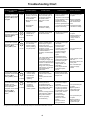
Troubleshooting ........................................................................................................................... 32
Electrostatic Discharge (ESD) Precautions ........................................................................................................ 32
Furnace Lockout ................................................................................................................................................... 32
Diagnostic Chart ................................................................................................................................................... 32
Maintenance.................................................................................................................................. 35
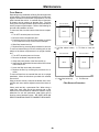
Filters ..................................................................................................................................................................... 35
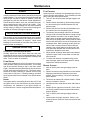
Burners .................................................................................................................................................................. 37
Induced Draft and Circulator Blowers ................................................................................................................. 37
Qualified Servicer Only ........................................................................................................................................ 37
Before Leaving an Installation .................................................................................................... 38
Repair and Replacement Parts .................................................................................................... 38
3
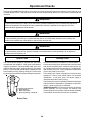
Safety Instructions
Recognize Safety Symbols, Words, and Labels
Please adhere to the following warnings and cautions when installing, adjusting, altering, servicing, or operating the
furnace. Failure to heed safety information increases the risk of personal injury, property damage, and/or product
damage.
WARNING
If the information in these instructions is not followed exactly, fire or explosion may result
causing property damage, personal injury or loss of life.
• Do not store or use gasoline or other flammable vapors and liquids in the
vicinity of this or any other appliance.
• What to do if you smell gas:
•
Do not try to light any appliance.
•
Do not touch any electrical switch; do not use any phone in your
building.
•
Immediately call your gas supplier from a neighbor’s phone. Follow
the gas supplier’s instructions.
•
If you cannot reach your gas supplier, call the fire department.
• Installation and service must be performed by a qualified installer,
service agency or the gas supplier.
WARNING
Should overheating occur or the gas supply fail to shut off, turn off the manual gas shut-off
valve external to the furnace before turning off the electrical supply.
WARNING
To prevent personal injury or death due to improper installation, adjustment, alteration,
service or maintenance, refer to this manual. For additional assistance or information,
consult a qualified installer, service agency or the gas supplier.
4
Safety Instructions
WARNING
To prevent possible death or personal injury due to asphyxiation, this Non-Condensing Gas
Fired Warm Air Furnaces must be Category I vented. Do not vent any of these furnaces using
Category III venting.
Provisions must be made for venting combustion products outdoors through a proper
venting system. The length of flue pipe could be a limiting factor in locating the furnace.
WARNING
This product contains or produces a chemical or chemicals which may cause serious illness
or death and which are known to the State of California to cause cancer, birth defects or other
reproductive harm.
WARNING
To prevent possible death, personal injury or property damage due to electrical shock, the
furnace must be located to protect the electrical components from water.
CAUTION
This unit must not be used as a “construction heater” during the finishing phases of
construction on a new structure. This type of use may result in premature failure of the unit
due to extremely low return air temperatures and exposure to corrosive or very dirty
atmospheres.
5
General Information
Shipping and Handling
All units are securely packed in shipping containers tested according to International Safe Transit Association
specifications. The carton must be checked upon arrival for external damage. If damage is found, a request for inspection
by carrier’s agent must be made in writing immediately.
The furnace must be carefully inspected on arrival for damage and bolts or screws which may have come loose in transit.
In the event of damage the consignee should:
1. Make a notation on delivery receipt of any visible damage to shipment or container.
2. Notify carrier promptly and request an inspection.
3. With concealed damage, carrier must be notified as soon as possible - preferably within five days.
4. File the claim with the following support documents within a nine month statute of limitations.
• Original or certified copy of the Bill of Lading, or indemnity bond.
• Original paid freight bill or indemnity in lieu thereof.
• Original or certified copy of the invoice, showing trade and other discounts or reductions.
• Copy of the inspection report issued by carrier’s representative at the time damage is reported to carrier.
The carrier is responsible for making prompt inspection of damage and for a thorough investigation of each claim. The
distributor or manufacturer will not accept claims from dealers for transportation damage.
Product Application
This furnace is primarily designed for residential home-heating applications. It is NOT designed or certified for use in
mobile homes, trailers or recreational vehicles. Neither is it designed or certified for outdoor applications. The furnace
must be installed indoors (i.e., attic space, crawl space, or garage area provided the garage area is enclosed with an
operating door).
This furnace can be used in the following non-industrial commercial applications:
Schools, Office buildings, Churches, Retail stores
Nursing homes, Hotels/motels, Common or office areas
In such applications , the furnace must be installed with the following stipulations:
•
•
•
•
•
It must be installed per the Installation Instructions provided and per local and national
codes.
It must be installed indoors in a building constructed on site.
It must be part of a ducted system and not used in a free air delivery application.
It must not be used as a “make-up” air unit.
All other warranty exclusions and restrictions apply. This furnace is an CSA dualcertified appliance and is appropriate for use with natural or propane gas.
6
General Information
Product Application (cont’d)
WARNING
Possible death, personal injury or property damage due to fire, explosion, smoke, soot, condensation, electrical
shock or carbon monoxide may result from improper installation, repair, operation, or maintenance of this product.
WARNING
To prevent death, personal injury or property damage due to fire, do not install this furnace in a mobile home,
trailer, or recreational vehicle.
To ensure proper furnace operation, install, operate and maintain this furnace in accordance with these installation and
operation instructions, all local building codes and ordinances. In their absence, follow the latest edition of the National
Fuel Gas Code (NFPA 54/ANSI Z223.1), and/or CAN/CSA B149 Installation Codes, local plumbing or waste water codes,
and other applicable codes.
A copy of the National Fuel Gas Code (NFPA 54/ANSI Z223.1) can be obtained from any of the following:
American National Standards Institute
1430 Broadway
New York, NY 10018
National Fire Protection Association
1 Batterymarch Park
Quincy, MA 02269
CSA International
8501 East Pleasant Valley
Cleveland, OH 44131
A copy of the CAN/CSA B149 Installation Codes can also be obtained from:
CSA International
178 Rexdale Boulevard
Etobicoke, Ontario, Canada M9W 1R3
The rated heating capacity of the furnace should be greater than or equal to the total heat loss of the area to be heated.
The total heat loss should be calculated by an approved method or in accordance with “ASHRAE Guide” or “Manual JLoad Calculations” published by the Air Conditioning Contractors of America.
7
General Information
Location Requirements and Considerations
WARNING
To prevent possible death, personal injury, equipment damage, or property damage the following bullet points must
be observed when installing the unit.
Follow the instructions listed below when selecting a furnace location. Refer also to the guidelines provided in the section
Combustion and Ventilation Air Requirements.
•
•
•
•
•
•
•
Centrally locate the furnace with respect to the
proposed or existing air distribution system.
Ensure the temperature of the return air entering the
furnace is between 55°F and 100°F when the furnace is heating.
Provisions must be made for venting combustion
products outdoors through a proper venting system.
The length of flue pipe could be a limiting factor in
locating the furnace.
Ensure adequate combustion air is available for the
furnace. Improper or insufficient combustion air can
expose building occupants to gas combustion products that could include carbon monoxide. Refer to
Condensate Drain Lines and Trap for further details.
The furnace must be level. If the furnace is to be set
on a floor that may become wet or damp at times, the
furnace should be supported above the floor on a
concrete base sized approximately 1-1/2" larger
than the base of the furnace.
Ensure upflow or horizontal furnaces are not installed directly on carpeting, or any other combustible material. The only combustible material allowed is wood.
•
•
•
Exposure to contaminated combustion air will result
in safety and performance-related problems. Do not
install the furnace where the combustion air is exposed to the following substances:
chlorinated waxes or cleaners
chlorine-based swimming pool chemicals
water softening chemicals
•
deicing salts or chemicals
carbon tetrachloride
halogen type refrigerants
cleaning solutions (such as perchloroethylene)
printing inks
paint removers
varnishes
hydrochloric acid
cements and glues
antistatic fabric softeners for clothes dryers
and masonry acid washing materials
If the furnace is used in connection with a cooling
unit, install the furnace upstream or in parallel with
the cooling unit. Premature heat exchanger failure
will result if the cooling unit is placed ahead of the
furnace.
If the furnace is installed in a residential garage,
position the furnace so that the burners and ignition
source are located not less than 18 inches (457 mm)
above the floor. Protect the furnace from physical
damage by vehicles.
If the furnace is installed horizontally, the furnace
access doors must be vertical so that the burners fire
horizontally into the heat exchanger. Do not install
the unit with the access doors on the “up/top” or
“down/bottom” side of the furnace.
Do not connect this furnace to a chimney flue that
serves a separate appliance designed to burn solid
fuel.
CLEARANCES AND ACCESSIBILITY
Installations must adhere to the clearances to combustible materials
which this furnace has been design certified to.
Allow clearances from the enclosure as shown on Specification Sheet for
fire protection, proper operation, and service access. These clearances
must be permanently maintained. The combustion and ventilating air
openings in the front and top panels of the furnace must never be
obstructed.
8
General Information
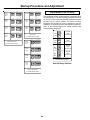
FURNACE SUSPENSION
above, return doors, windows, exhaust fans, fireplace dampers
and any other gas burning appliance to their previous conditions
of use;
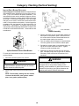
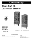
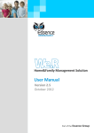
If suspending the furnace from rafters or joist, use 3/8"
threaded rod and 2”x2”x1/8” angle iron as shown below.
The length of rod will depend on the application and the
clearances necessary.
g. If improper venting is observed during any of the above tests,
the common venting system must be corrected.
PROVIDE 8" MINMUM CLEARANCE BETWEEN
3/8" DIAMETER
CENTER ROD AND FURNACE CABINET
THREADED ROD
TO ALLOW FOR CIRCULATOR BLOWER REMOVAL
Corrections must be in accordance with the latest edition
of the National Fuel Gas Code NFPA 54/ANSI Z223.1 and/
or CSA B149 Installation Codes.
(6 PLACES)
ASSURE FURNACE IS LEVEL FROM
HOLD
END TO END AND HAS A SLIGHT
DOWN
If resizing is required on any portion of the venting system,
use the appropriate table in Appendix G in the latest edition
of the National Fuel Gas Code ANSI Z223.1 and/or
CSA B149 Installation Codes.
FORWARD TILT WITH THE FRONT
NUTS
OF THE FURNACE 0"-3/4"BELOW
THE BACK OF THE FURNACE
SUPPORT
NUTS
Thermostat Requirements
2"X2"X3/8" DIAMETER
ANGLE IRON
POSITION AS CLOSE AS POSSIBLE
TILT OUTWARD TO ALLOW
(3 PLACES)
TO BLOWER DECK TO ALLOW FOR
FOR DOOR AND CIRCULATOR
CIRCULATOR BLOWER REMVOAL
BLOWER REMOVAL
Suspended Furnace
The two stage furnace requires a two stage thermostat for
proper operation. A two stage thermostat will have a “W2”
terminal in addition to a “W1” terminal. Refer to Electrical
Connections for proper hookup.
Existing Furnace Removal
Thermostat Location
NOTE: When an existing furnace is removed from a
venting system serving other appliances, the venting
system may be too large to properly vent the remaining
attached appliances.
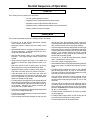
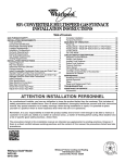
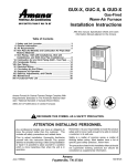
In an area having good air circulation, locate the thermostat about five feet high on a vibration-free inside wall. Do
not install the thermostat where it may be influenced by any
of the following:
The following vent testing procedure is reproduced from the
American National Standard/National Standard of Canada
for Gas-Fired Central Furnaces ANSI Z21.47-1998,
CSA-2.3-M98 Section 1.23.1.
• Drafts, or dead spots behind doors, in corners, or
•
•
•
•
•
•
The following steps shall be followed with each appliance connected to
the venting system placed in operation, while any other appliances
connected to the venting system are not in operation:
a. Seal any unused openings in the venting system;
b. Inspect the venting system for proper size and horizontal pitch,
as required by the National Fuel Gas Code, ANSI Z223.1 or the
CSA B149 Installation Codes and these instructions. Determine
that there is no blockage or restriction, leakage, corrosion and
other deficiencies which could cause an unsafe condition;
c. In so far as practical, close all building doors and windows and
all doors between the space in which the appliance(s) connected
to the venting system are located and other spaces of the
building. Turn on clothes dryers and any appliance not connected to the venting system. Turn on any exhaust fans, such as
range hoods and bathroom exhausts, so they shall operate at
maximum speed. Do not operate a summer exhaust fan. Close
fireplace dampers;
under cabinets.
Hot or cold air from registers.
Radiant heat from the sun.
Light fixtures or other appliances.
Radiant heat from a fireplace.
Concealed hot or cold water pipes, or chimneys.
Unconditioned areas behind the thermostat, such
as an outside wall.
DRAFTS OR DEAD SPOTS
-BEHIND DOORS
-IN CORNERS
-UNDER CABINETS
HOT
COLD
d. Follow the lighting instructions. Place the appliance being
inspected in operation. Adjust thermostat so appliance shall
operate continuously;
Thermostat Influences
e. Test for draft hood equipped spillage at the draft hood relief
opening after 5 minutes of main burner operation. Use the flame
of a match or candle;
Consult the instructions packaged with the thermostat for
mounting instructions and further precautions.
f. After it has been determined that each appliance connected to
the venting system properly vents when tested as outlined
9
Combustion and Ventilation Air Requirements
WARNING
Possible death, personal injury or property damage may occur if the furnace is not provided with enough fresh air
for proper combustion and ventilation of flue gases. Most homes require outside air to be supplied to the furnace
area.
Improved construction and additional insulation in buildings have reduced heat loss by reducing air filtration and escape
around doors and windows. These changes have helped in reducing heating/cooling costs but have created a problem
supplying combustion and ventilation air for gas fired and other fuel burning appliances. Appliances that pull air out of
the house (clothes dryers, exhaust fans, fireplaces, etc.) increase the problem by starving appliances for air.
House depressurization can cause back drafting or improper combustion of gas-fired appliances, thereby exposing
building occupants to gas combustion products that could include carbon monoxide.
If this furnace is to be installed in the same space with other gas appliances, such as a water heater, ensure there is an
adequate supply of combustion and ventilation air for the other appliances. Refer to the latest edition of the National Fuel
Gas Code NFPA 54/ANSI Z223.1 (Section 5.3), or CSA B149 Installation Codes (Sections 7.2, 7.3, or 7.4), or applicable
provisions of the local building codes for determining the combustion air requirements for the appliances.
This furnace must use indoor air for combustion. It cannot be installed as a direct vent (i.e., sealed combustion) furnace.
The burner box is present only to help reduce sound transmission from the burners to the occupied space.
Most homes will require outside air be supplied to the furnace area by means of ventilation grilles or ducts connecting
directly to the outdoors or spaces open to the outdoors such as attics or crawl spaces.
The following information on air for combustion and ventilation
is reproduced from the National Fuel Gas Code
NFPA 54/ANSI Z223.1 Section 5.3.
(d) In addition to air needed for combustion, air shall be supplied for
ventilation, including all air required for comfort and proper
working conditions for personnel.
5.3.1 General:
(e) While all forms of building construction cannot be covered in
detail, air for combustion, ventilation and dilution of flue gases
for gas utilization equipment vented by natural draft normally
may be obtained by application of one of the methods covered
in 5.3.3 and 5.3.4.
(a) The provisions of 5.3 apply to gas utilization equipment installed in buildings and which require air for combustion,
ventilation and dilution of flue gases from within the building.
They do not apply to (1) direct vent equipment which is
constructed and installed so that all air combustion is obtained
from the outside atmosphere and all flue gases are discharged to
the outside atmosphere, or (2) enclosed furnaces which incorporate an integral total enclosure and use only outside air for
combustion and dilution of flue gases.
(f) Air requirements for the operation of exhaust fans, kitchen
ventilation systems, clothes dryers, and fireplaces shall be
considered in determining the adequacy of a space to provide
combustion air requirements.
(b) Equipment shall be installed in a location in which the facilities
for ventilation permit satisfactory combustion of gas, proper
venting and the maintenance of ambient temperature at safe
limits under normal conditions of use. Equipment shall be
located so as not to interfere with proper circulation of air. When
normal infiltration does not provide the necessary air, outside
air shall be introduced.
5.3.2 Equipment Located in Unconfined Spaces:
In unconfined spaces (see definition below) in buildings, infiltration
may be adequate to provide air for combustion ventilation and
dilution of flue gases. However, in buildings of tight construction
(for example, weather stripping, heavily insulated, caulked, vapor
barrier, etc.), additional air may need to be provided using the
methods described in 5.3.3-b or 5.3.4.
(c) In addition to air needed for combustion, process air shall be
provided as required for: cooling of equipment or material,
controlling dew point, heating, drying, oxidation or dilution,
safety exhaust, odor control, and air for compressors.
Space, Unconfined.
For purposes of this Code, a space whose volume is not less than 50
cubic feet per 1,000 BTU per hour of the aggregate input rating of
all appliances installed in that space. Rooms communicating directly with the space in which the appliances are installed through
openings not furnished with doors, are considered a part of the
unconfined space.
10
Combustion and Ventilation Air Requirements
5.3.3 Equipment Located in Confined Spaces:
(a) All Air from Inside the Building: The confined space shall be
provided with two permanent openings communicating directly
with an additional room(s) of sufficient volume so that the
combined volume of all spaces meets the criteria for an unconfined space. The total input of all gas utilization equipment
installed in the combined space shall be considered in making
this determination. Each opening shall have a minimum free area
of 1 square inch per 1,000 BTU per hour of the total input rating
of all gas utilization equipment in the confined space, but not less
than 100 square inches. One opening shall be within 12 inches of
the top and one within 12 inches of the bottom of the enclosure.
2. When communicating with the outdoors through vertical
ducts, each opening shall have a minimum free area of 1
square inch per 4,000 BTU per hour of total input rating of
all equipment in the enclosure.
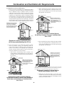
Chimney or Gas Vent
Ventilation louvers
(each end of attic)
NOTE: The inlet and outlet air
openings must each have a free
area of not less than one square
inch per 4000 BTU of the
total input rating of all equipment
in the enclosure.
Chimney or Gas Vent
NOTE: Each opening must have
a free area of not less than one
square inch per 1000 BTU of
the total input rating of all equipment in the enclosure, but not
less than 100 square inches.
Outlet Air
Furnace
Water
Heater
Inlet air duct
[ends 1 ft (300 mm)
above floor]
Opening
Furnace
Water
Heater
Equipment Located in Confined Spaces;
All Air from Outdoors Through Ventilated Attic.
See 5.3.3-b.
Opening
Equipment Located in Confined Spaces;
All Air from Inside Building. See 5.3.3-a.
3. When communicating with the outdoors through horizontal
ducts, each opening shall have a minimum free area of 1
square inch per 2,000 BTU per hour of total input rating of
all equipment in the enclosure.
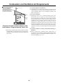
(b) All Air from Outdoors: The confined space shall be provided
with two permanent openings, one commencing within 12
inches of the top and one commencing within 12 inches of the
bottom of the enclosure. The openings shall communicate
directly, or by ducts, with the outdoors or spaces (crawl or attic)
that freely communicate with the outdoors.
Chimney or Gas Vent
1. When directly communicating with the outdoors, each
opening shall have a minimum free area of 1 square inch per
4,000 BTU per hour of total input rating of all equipment in
the enclosure.
Chimney or Gas Vent
Outlet air duct
Ventilation louvers
(each end of attic)
NOTE: The inlet and outlet air
openings must each have a free
area of not less than one square
inch per 4000 BTU of the
total input rating of all equipment
in the enclosure.
Furnace
NOTE: The air duct openings
must have a free area of not
less than one square inch per
2000 BTU of the total input
rating of all equipment in the
enclosure*.
Water
Heater
Inlet air duct
Outlet Air
Furnace
Water
Heater
*If the appliance room is located against an outside wall and the air openings communicate
directly with the outdoors, each opening shall have a free area of not less than one square inch
per 4,000 BTU per hour of the total input rating of all appliances in the enclosure.
Inlet Air
Equipment Located in Confined Spaces;
All Air from Outdoors. See 5.3.3-b.
Alternate
air inlet
4. When ducts are used, they shall be of the same crosssectional area as the free area of the openings to which they
connect. The minimum dimension of rectangular air ducts
shall not be less than 3 inches.
Ventilation louvers for
unheated crawl space
Equipment Located in Confined Spaces;
All Air from Outdoors—Inlet Air from Ventilated
Crawl Space and Outlet Air to Ventilated Attic.
See 5.3.3-b
11
Combustion and Ventilation Air Requirements
NOTE: The single opening must have
a free area of not less than one
square inch per 3000 BTU of
the total input rating of all equipment in the enclosure, but not less than
the sum of the areas of all vent
connectors in the confined space.
5.3.4 Specially Engineered Installations:
Chimney or Gas Vent
The requirements of 5.3.3 shall not necessarily govern when special
engineering, approved by the authority having jurisdiction, provides an adequate supply of air for combustion, ventilation, and
dilution of flue gases.
5.3.5 Louvers and Grilles:
Opening
Furnace
Water
Heater
In calculating free area in 5.3.3, consideration shall be given to the
blocking effect of louvers, grilles or screens protecting openings.
Screens used shall not be smaller than 1/4 inch mesh. If the area
through a design of louver or grille is known, it should be used in
calculating the size of opening required to provide the free area
specified. If the design and free area is not known, it may be
assumed that wood louvers will have 20-25 percent free area and
metal louvers and grilles will have 60-75 percent free area. Louvers
and grilles shall be fixed in the open position or interlocked with the
equipment so that they are opened automatically during equipment
operation.
Alternate
Opening
Location
Equipment Located in Confined Spaces; All Air
from Outdoors - Single Air Opening. See 5.3.3-b.
5.3.6 Special Conditions Created by Mechanical Exhausting or
Fireplaces:
5. When directly communicating with the outdoors, the single
opening shall have a minimum free area of 1 square inch per
3,000 BTU per hour of total input rating of all equipment in
the enclosure.
Operation of exhaust fans, ventilation systems, clothes dryers, or
fireplaces may create conditions requiring special attention to avoid
unsatisfactory operation of installed gas utilization equipment. Air
from Inside Building. See 5.3.3-a.
12
Category I Venting (Vertical Venting)
WARNING
To prevent possible death or personal injury due to asphyxiation, this Non-Condensing Gas Fired Warm Air
Furnace must be Category I vented. Do not vent using Category III venting.
Category I Venting is venting at a non-positive pressure. A furnace vented as Category I is considered a fan-assisted
appliance and the vent system does not have to be “gas tight.” NOTE: Single stage gas furnaces with induced draft
blowers draw products of combustion through a heat exchanger allowing, in some instances, common venting
with natural draft appliances (i.e. water heaters).
All installations must be vented in accordance with National Fuel Gas Code NFPA 54/ANSI Z223.1 - latest edition. In
Canada, the furnaces must be vented in accordance with the National Standard of Canada, CAN/CSA B149.1 and CAN/
CSA B149.2 - latest editions and amendments.
NOTE: The vertical height of the Category I venting system must be at least as great as the horizontal length of the venting
system.
WARNING
To prevent possible death or personal injury due to asphyxiation, common venting with other manufacturer’s
induced draft appliances is not allowed.
Common venting of this furnace is allowed with the addition of a common vent kit (CVK) for each appliance. Contact the
local installing dealer, distributor or us directly for more information.
The minimum vent diameter for the Category I venting system is as shown below:
MODEL
70
90
115
140
MINIMUM VENT
DIAMETER
4 Inch
4 Inch
5 Inch
5 Inch
Under some conditions, larger vents than those shown above may be required or allowed.
When an existing furnace is removed from a venting system serving other appliances, the venting system may be too large
to properly vent the remaining attached appliances.
13
Category I Venting (Vertical Venting)
INDUCED DRAFT BLOWER RELOCATION
Upflow Upright or Horizontal units are shipped with the
induced draft blower discharging from the top of the furnace. (“Top” is as viewed for an upflow installation.) The
induced draft blower can be rotated 90 degrees counterclockwise for Category I venting, with the airflow horizontal
left to right. For horizontal installations, a four inch single
wall pipe can be used to extend the induced draft blower
outlet 1/2” beyond the furnace cabinet. Vent the furnace in
accordance with the National Fuel Gas Code NFPA 54/
ANSI Z223.1 - latest edition. In Canada, vent the furnace
in accordance with the National Standard of Canada, CAN/
CSA B149.1 and CAN/CSA B149.2 - latest editions and
amendments.
Blower Assembly
3. Remove and save the four screws which hold the rotation plate on the partition panel. Note that one of
the screws which hold the induced draft blower on
the rotation plate needs to be removed.
4. Turn the rotation plate 90 degrees counterclockwise.
The inner gasket must turn with the rotation plate.
Supply
Air
5. Reinstall the rotation plate on the partition panel, using the four screws removed in step 3. Tighten
screws to provide an airtight seal.
6. Make sure all wires are at least one inch from flue
pipe. Relocate junction box to right side of cabinet if
necessary. Refer to Electrical Connections for instructions.
Upflow Rotated Induced Draft Blower
To rotate the induced draft blower counterclockwise proceed as follows:
1. Disconnect electrical power from furnace.
WARNING
WARNING
To prevent death or serious illness to building
occupants due to flue products leaking into the
building, proper installation of gaskets and screws is
essential for providing a gas tight seal between the
partition panel and the induced draft blower.
To prevent death or personal injury due to electrical
shock, disconnect electrical power.
2. Remove the round cutout from the side of the furnace.
NOTE: The assembly, starting from the outside,
is induced draft blower, outer gasket, rotation
plate, inner gasket, partition panel).
14
Category I Venting (Vertical Venting)
WARNING
To prevent death, personal injury or property damage due to fire or explosion, a qualified servicer must determine
the reason the rollout protection device opened before the device is reset.
ROLLOUT PROTECTION DEVICE RELOCATION
Furnaces installed horizontal right-to-left airflow, require
the rollout protection device be relocated. This device
closes the gas valve if the burner flames are not drawn into
the heat exchanger.
Vent
Supply
Air
Return
Air
Right To Left Installation
To relocate:
1. Disconnect electrical power.
Rollout Switch Relocation
WARNING
6. Secure rollout wires to manifold and insure no wires
can come in contact with burners or other hot surfaces.
To prevent death or personal injury due to electric
shock, disconnect electrical power.
7. Push the button to confirm the rollout control is in the
closed position.
2. Remove the cover from the burner box. Save the
screws that held it in place. (Note: There are several
screw holes, but only four screws. This is intentional,
and not a manufacturing defect.)
8. Replace the cover on the burner box, replacing the
screws from Step 2.
3. As shipped, the rollout protection device is located
near the flame sensor end of the manifold assembly.
Remove and save the mounting screws.
4. For most installations, it will not be necessary to remove the wires from the rollout protection device.
5. For horizontal-left installations, a hole is provided
near the igniter end of the manifold assembly. Insert
the rollout protection device into this hole and attach
with screws removed in Step 3.
15
Electrical Connections
WARNING
To avoid the risk of electrical shock, wiring to the unit must be properly polarized and grounded.
WARNING
To avoid electrical shock, injury or death, disconnect electrical power before servicing or changing any electrical
wiring.
CAUTION
Label all wires prior to disconnection when servicing controls. Wiring errors can cause improper and dangerous
operation. Verify proper operation after servicing.
WARNING
To avoid the risk of electrical shock, injury, or death, the furnace must be electrically grounded in accordance with
local codes or, in their absence, with the latest edition of The National Electric Code.
Wiring Harness
Junction Box Relocation
The wiring harness is an integral part of this furnace. Field
alteration to comply with electrical codes should not be
required. Wires are color and number coded for identification purposes. Refer to the wiring diagram for wire routings.
If any of the original wire as supplied with the furnace must
be replaced, it must be replaced with wiring material having
a temperature rating of at least 105°C. Any replacement
wiring must be copper conductor.
Line polarity must be observed when making field connections. Line voltage connections can be made through
either the right or left side panel. The furnace is shipped
configured for a right side electrical connection with the
junction box located on the left side of the furnace. To
make electrical connections through the opposite side of
the furnace, the junction box must be relocated to the other
side prior to making electrical connections. To relocate the
junction box, perform the steps that follow.
115 Volt Line Connections
CAUTION
Before proceeding with electrical connections, ensure that
the supply voltage, frequency, and phase correspond to
that specified on the unit rating plate. Power supply to the
furnace must be N.E.C. Class 1, and must comply with all
applicable codes. The furnace must be electrically grounded
in accordance with local codes or, in their absence, with the
latest edition of The National Electric Code, ANSI NFPA 70
and/or The Canadian Electric Code CSA C22.1.
Edges of sheet metal holes may be sharp. Use
gloves as a precaution when removing hole plugs.
1. Remove both doors from the furnace.
2. Remove and save the screws holding the junction
box to the right side of the furnace.
Use a separate fused branch electrical circuit containing
properly sized wire, and fuse or circuit breaker. The fuse
or circuit breaker must be sized in accordance with the
maximum overcurrent protection specified on the unit
rating plate. An electrical disconnect must be provided at
the furnace location.
3. Disconnect the hose from the pressure switch.
Leave the other end attached to the induced draft
blower.
4. Remove four wires to the pressure switch assembly.
5. Swap locations of the two bushings in the junction
box.
NOTE: Line polarity must be observed when making
field connections.
16
Electrical Connections
6. Rotate the junction box 180 degrees so the access
panel continues to face forward. The open snap
bushing should now be on the left.
NOTE: Do not use gas piping as an electrical ground.
To confirm proper unit grounding, turn off the electrical
power and perform the following check.
7. Attach pressure switch bracket to left side of furnace
where the junction box was using the screws saved
in Step 4. The “L” bracket must point toward the
front of the furnace. Reroute pressure switch wires
through the split grommet on the left side of the
blower deck. Reconnect wires using the wiring diagram inside the blower door.
1. Measure resistance between the neutral (white) connection and one of the burners.
2. Resistance should measure 10 ohms or less.
This furnace is equipped with a blower door interlock
switch which interrupts unit voltage when the blower door
is opened for servicing. Do not defeat this switch.
8. Reroute remaining wires through split grommet on
the right side of the blower deck.
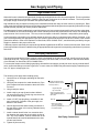
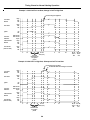
24 VOLT THERMOSTAT WIRING
NOTE: Wire routing must not interfere with circulator
blower operation, filter removal, or routine maintenance.
As a two-stage furnace, the furnace integrated control
module provides terminals for both “W1” and “W2”, and
“YLO” and “Y” thermostat connections. This allows the
furnace to support the following system applications: ‘TwoStage Heating Only’, ‘Two-Stage Heating with SingleStage Cooling’, and ‘Two-Stage Heating with Two-Stage
Cooling’. Refer to the following figures and table for proper
connections to the integrated control module.
9. Insert remaining wires through the open bushing in
the bottom of the junction box.
10. Attach the junction box to the right side of the furnace, using the screws removed in step 2.
11. Reconnect the hose to the pressure switch.
12. Check the location of the pressure hose and all wiring. Confirm that it will not be damaged by heat from
the burners or by the rotation of the fan. Also confirm
that wiring location will not interfere with filter removal or other maintenance.
Low voltage connections can be made through either the
right or left side panel. Thermostat wiring entrance holes
are located in the blower compartment. Wire routing must
not interfere with circulator blower operation, filter removal,
or routine maintenance.
After the junction box is in the desired location, use washers to connect field-supplied conduit to the junction box in
accordance with NEC and local codes. Connect hot, neutral, and ground wires as shown in the furnace wiring
diagram. The wires and ground screw are located in the
furnace junction box.
This furnace is equipped with a 40 VA transformer to
facilitate use with most cooling equipment. Consult the
wiring diagram, located on the blower compartment door,
for further details of 115 Volt and 24 Volt wiring.
Low voltage wires may be connected to the terminal strip
as shown in the “Integrated Ignition Control” figure.
IMPORTANT NOTE: To avoid possible equipment malfunction, route the low voltage wires to avoid interference
with filter removal or other maintenance.
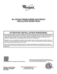
SINGLE STAGE THERMOSTAT APPLICATION
WARNING
W
Y
To avoid the risk of electrical shock, injury, or death,
the furnace must be electrically grounded in
accordance with local codes or, in their absence,
with the latest edition of The National Electric Code.
O
YLO
Y
(
B/C
G
R
G
R
)
Thermostat
Single-Stage Heating
with
Single-Stage Cooling
W1
W2
DEHUM
TWIN
Furnace Integrated
Control Module
NEU
To ensure proper unit grounding, the ground wire should
run from the furnace ground screw located inside the
furnace junction box all the way back to the electrical panel.
Y
C
HOT
Dehumidistat
[Optional]
Remote
Condensing Unit
(Single-Stage Cooling)
Single-Stage Heating with Single-Stage Cooling
NOTE: To apply a single-stage heating thermostat, the
thermostat selector jumper on the integrated Control
module must be set on single stage.
17
Electrical Connections
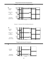
W2
(
W1
Y
The furnace’s integrated ignition control is equipped with
line voltage accessory terminals for controlling power to an
optional field-supplied humidifier and/or electronic air
cleaner.
Thermostat
Two-Stage Heating
with
Single-Stage Cooling
)
The accessory load specifications are as follows:
YLO
Y
B/C
R
G
R
W1
W2
DEHUM
TWIN
Humidifier
Electronic Air Cleaner
Furnace Integrated
Control Module
Turn OFF power to the furnace before installing any
accessories. Follow the humidifier or air cleaner manufacturers’ instructions for locating, mounting, grounding, and
controlling these accessories. Accessory wiring connections are to be made through the 1/4" quick connect
terminals provided on the furnace integrated ignition control. The humidifier and electronic air cleaner hot and
neutral terminals are identified as HUM and EAC. All field
wiring must conform to applicable codes. Connections
should be made as shown in the “Accessories Wiring”
figure.
NEU
Y
HOT
C
Dehumidistat
[Optional]
Remote
Condensing Unit
(Single-Stage Cooling)
Two-Stage Heating with Single-Stage Cooling
Thermostat
Two-Stage Heating
with
Two-Stage Cooling
(
W2
YLO
W1
Y
1.0 Amp maximum at 120 VAC
1.0 Amp maximum at 120 VAC
)
Control Module
Neutral 120 VAC
B/C
G
R
W1
W2
DEHUM
TWIN
Furnace Integrated
Control Module
NEU
YLO
Y
C
HOT
Dehumidistat
[Optional]
Optional
Accessories
Remote
Condensing Unit
(Two-Stage Cooling)
{
Hum
Y
Hum
YLO
EAC
O
R
Line
Transformer
Hot 120 VAC
G
EAC
Transformer
Line
O
G
Air Cleaner
Humidifier
Accessories Wiring
Two-Stage Heating with Two-Stage Cooling
If it is necessary for the installer to supply additional line
voltage wiring to the inside of the furnace, the wiring must
conform to all local codes, and have a minimum temperature rating of 105°C. All line voltage wire splices must be
made inside the furnace junction box.
Thermostat Diagrams
This furnace is equipped with a 40 VA transformer to
facilitate use with most cooling equipment. Consult the
wiring diagram, located on the blower compartment door,
for further details of 115 Volt and 24 Volt wiring.115 Volt
Line Connection of Accessories (Humidifier and Electronic Air Cleaner)
The integrated ignition control humidifier terminals (HUM)
are energized with 115 volts whenever the induced draft
blower is energized. The integrated ignition control electronic air cleaner terminals (EAC) are energized with 115
volts whenever the circulator blower is energized.
WARNING
To avoid electrical shock, injury or death, disconnect
electrical power before servicing, or changing any
electrical wiring.
18
Gas Supply and Piping
Proper Piping Practice
The gas line installation must comply with local codes, or in the absence of local codes, with the latest edition of the
National Fuel Gas Code NFPA 54/ANSI Z223.1.
IMPORTANT NOTE: This unit is factory set to operate on natural gas at the altitudes shown on the rating plate. The plate
is stamped with the model number, type of gas and gas input rating. Make sure the unit is equipped to operate on the
type of gas available.
DO NOT VARY FROM THE MINIMUM SUPPLY PRESSURE GIVEN IN TABLE 1.
Doing so could create ignition problems.
DO NOT EXCEED THE RATED INPUT SHOWN ON THE RATING PLATE.
Overfiring of the unit could result in premature heat exchanger failure.
DO NOT UNDERSIZE THE NATURAL/PROPANE GAS PIPING FROM THE METER/TANK TO THE UNIT.
Doing so could cause unsatisfactory operation or equipment damage due to under firing of equipment.
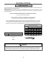
When sizing a trunk line (Table 2), include all appliances on that line that could be operated simultaneously.
Natural Gas Capacity of Pipe
in Cubic Feet of Gas Per Hour (CFH)
Nominal Black Pipe Size (inches)
Length of
Pipe in Feet
1
1/2
3/4
1 1/4
1 1/2
10
132
278
520
1050
1600
20
92
190
350
730
1100
30
73
152
285
590
980
40
63
130
245
500
760
50
56
115
215
440
670
60
50
105
195
400
610
70
46
96
180
370
560
80
43
90
170
350
530
90
40
84
160
320
490
100
38
79
150
305
460
Pressure = .50 PSIG or less and Pressure Drop of 0.3" W.C. (Based
on 0.60 Specific Gravity Gas)
Inlet Gas Pressure
Natural
Propane
Min. 5.0" W.C., Max. 10.0" W.C.
Min. 11.0" W.C., Max. 13.0" W.C.
Inlet Gas Pressure Must Not Exceed the Maximum Value Shown in
Table Above.
CFH =
BTUH Furnace Input
Heating Value of Gas (BTU/Cubic Foot)
Table 2
Table 1
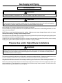
WARNING
To prevent death, personal injury or property damage when either using propane gas alone or at higher altitudes,
obtain and install the proper conversion kit(s). Failure to do so can result in unsatisfactory operation and/or
equipment damage. High altitude kits are for U.S. installations only and are not approved for use in Canada.
19
Gas Supply and Piping
High Altitude Derate
When this furnace is installed at high altitude, the appropriate High Altitude orifice kit must be applied. This is required due
to the natural reduction in the density of both the gas fuel and combustion air as altitude increases. The kit will provide
the proper design certified input rate within the specified altitude range.
High altitude kits are purchased according to the installation altitude and usage of either natural or propane gas. Refer
to the product Specification Sheet for a tabular listing of appropriate altitude ranges and corresponding manufacturer’s high
altitude (natural, propane gas, and/or pressure switch) kits.
Do not derate the furnace by adjusting the manifold pressure to a lower pressure than specified on the furnace rating plate.
The combination of the lower air density and a lower manifold pressure will prohibit the burner orifice from drawing the
proper amount of air into the burner. This may cause incomplete combustion, flashback, and possible yellow tipping.
In some areas the gas supplier may artificially derate the gas in an effort to compensate for the effects of altitude. If the
gas is artificially derated, the appropriate orifice size must be determined based upon the BTU/ft3 content of the derated
gas and the altitude. Refer to the National Fuel Gas Code, NFPA 54/ANSI Z223.1, and information provided by the gas
supplier to determine the proper orifice size.
A different pressure switch may be required at high altitude regardless of the BTU/ft3 content of the fuel used. Refer to the
product Specification Sheet for a tabular listing of appropriate altitude ranges and corresponding manufacturer’s pressure
switch kits.
Gas Piping Connections
The gas piping supplying the furnace must be properly sized based on the gas flow required, specific gravity of the gas,
and length of the run. The gas line installation must comply with local codes, or in their absence, with the latest edition
of the National Fuel Gas Code, NFPA 54/ANSI Z223.1.
To connect the furnace to the building’s gas piping, the installer must supply a ground joint union, drip leg, manual shutoff
valve, and line and fittings to connect to gas valve. In some cases, the installer may also need to supply a transition piece
from 1/2" pipe to a larger pipe size.
The following rules apply when installing piping:
1. Use black iron or steel pipe and fittings for the building piping.
Location of Manual Valve
(Installed Ahead of Ground
Joint Pipe Union)
2. Use pipe joint compound on male threads only. Pipe
joint compound must be resistant to the action of the
fuel used.
Height Required
By Local Code
3. Use ground joint unions.
4. Install a drip leg to trap dirt and moisture before it
can enter the gas valve. The drip leg must be a minimum of three inches long.
Ground Joint Pipe Union
To Be Installed Ahead Of
Gas Valve
5. Install 1/8” NPT pipe plug fitting, accessible for test
gage connection, upstream of the gas supply connection to the furnace.
Drip Leg
``
Reducing Coupling
1/2" x 1/8" with 1/8"
Pipe Plug To Measure
Line Gas Pressure
6. Use two pipe wrenches when making connection to
the gas valve to keep it from turning. Maintain factory
shipped orientation.
7. Install a manual shutoff valve in a convenient location between the meter and the unit within six feet of
unit. Any union installed, must be downstream of the
manual shutoff valve and located between the shutoff valve and furnace.
Gas Piping Connections
8. Tighten all joints securely.
20
Gas Supply and Piping
9.
•
•
•
•
The unit must be connected to the building piping by
one of the following methods:
Rigid metallic pipe and fittings
Semirigid metallic tubing and metallic fittings (Aluminum alloy tubing must not be used in exterior locations)
Listed gas appliance connectors used in accordance with the terms of their listing that are completely in the same room as the equipment
Protect connectors and semirigid tubing against
physical and thermal damage when installed. Ensure aluminum-alloy tubing and connectors are
coated to protect against external corrosion when in
contact with masonry, plaster, or insulation, or subjected to repeated wetting by liquids such as water
(except rain water), detergents, or sewage.
Gas Inlet Through Furnace Left Side
Inlet Piping
When the gas piping enters through the right side of the
furnace, the installer must supply the following fittings
(starting from the gas valve):
• 90 degree elbows (2).
• Close nipple.
• Straight pipe to reach the exterior of the furnace.
A ground joint union, drip leg, and manual shutoff valve
must also be supplied by the installer. In some cases, the
installer may also need to supply a transition piece from
1/2" to another pipe size.
When the gas piping enters through the left side of the
furnace, the installer must supply the following fittings
(starting from the gas valve):
Gas Inlet Through Furnace Bottom Side
• Straight pipe to reach the exterior of the furnace.
• A ground joint union, drip leg, and manual shutoff valve
must also be supplied by the installer. In some cases,
the installer may also need to supply a transition piece
from 1/2 inch to another pipe size.
Gas Inlet Through Furnace Top Side
Gas Inlet Through Furnace Right Side
21
Gas Supply and Piping
Gas Piping Checks
WARNING
To avoid the possibility of explosion or fire, never use a match or open flame to test for leaks.
CAUTION
To prevent personal injury or property damage due to fire, the following instructions must be performed regarding
gas connections, pressure testing, location of shutoff valve and installation of gas piping.
Before placing unit in operation, leak test the unit and gas connections.
Check for leaks using an approved chloride-free soap and water solution, an electronic combustible gas detector, or other
approved testing methods.
NOTE: Never exceed specified pressures for testing. Higher pressure may damage the gas valve and cause
subsequent overfiring, resulting in heat exchanger failure.
Disconnect this unit and shutoff valve from the gas supply piping system before pressure testing the supply piping system
with pressures in excess of 1/2 psig (3.48 kPa).
Isolate this unit from the gas supply piping system by closing its external manual gas shutoff valve before pressure testing
supply piping system with test pressures equal to or less than 1/2 psig (3.48 kPa).
Propane Gas and/or High Altitude Installations
WARNING
Possible death, personal injury or property damage may occur if the correct conversion kits are not installed. The
appropriate kits must be applied to insure safe and proper furnace operation. All conversions must be performed
by a qualified installer or service agency.
This furnace is shipped from the factory configured for natural gas at standard altitude. Propane gas installations require
an orifice change to compensate for the energy content difference between natural and propane gas.
High altitude installations may require both a pressure switch and an orifice change. These changes are necessary to
compensate for the natural reduction in the density of both the gas fuel and the combustion air at higher altitude.
Refer to the product Specification Sheet for a tabular listing of appropriate manufacturer’s kits for propane gas and/or high
altitude installations. The indicated kits are required to insure safe and proper furnace operation. All conversions must
be performed by a qualified installer or service agency.
22
Propane Gas Tanks and Piping
WARNING
PERSONAL INJURY HAZARD
To prevent death, personal injury, or property damage due to fire or explosion from a propane gas leak, install a
gas detecting warning device. A gas detecting warning device is the only reliable way to detect a propane gas
leak. Do not rely on smell as rust can reduce the level of odorant in propane gas.
Remember:
•
•
•
Propane gas is heavier than air and leaking gas can settle in any low area or confined space.
A propane gas odor can fade, making the gas undetectable.
A warning device is a required item, if the propane gas unit is installed in either a basement, an excavated area or
a confined space.
If the presence of gas is suspected:
•
•
•
•
Do not try to light any appliance.
Do not touch any electrical switch or use any phone in your building.
Immediately call your gas supplier from a neighbor’s phone. Follow the gas supplier’s instructions.
If you cannot reach your gas supplier, call the fire department.
IN CANADA “THE CONVERSION SHALL BE CARRIED OUT IN ACCORDANCE WITH THE REQUIREMENTS OF
THE PROVINCIAL AUTHORITIES HAVING JURISDICTION AND IN ACCORDANCE WITH THE REQUIREMENTS OF
THE CAN/CSA B149.1 AND B149.2 INSTALLATION CODE.”
IMPORTANT NOTE: Propane gas conversion kits must
be installed to convert units to propane gas. See
Specification Sheet for kit part number for this model.
All propane gas equipment must conform to the safety
standards of the National Board of Fire Underwriters (See
NBFU Manual 58).
Since propane gas will quickly dissolve white lead and
most standard commercial compounds, special pipe dope
must be used. Shellac-based compounds resistant to the
actions of liquefied petroleum gases such as Gasolac®,
Stalactic®, Clyde’s® or John Crane® are satisfactory.
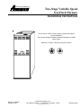
Refer to the following illustration for typical propane gas
installations.
For satisfactory operation, propane gas supply pressure
must be 11 inch W.C. at the unit manifold with all gas
appliances in operation. Maintaining proper gas pressure
depends on three main factors:
5 to 15 PSIG
(20 PSIG Max.)
First Stage
Regulator
1. Vaporization rate, which depends on (a) temperature
of the liquid, and (b) wetted surface area of the container or containers.
200 PSIG
Maximum
2. Proper pressure regulation. (Two-stage regulation is
recommended for both cost and efficiency).
3. Pressure drop in lines between regulators, and between second stage regulator and the appliance.
Pipe size required will depend on length of pipe run
and total load of all appliances.
Continuous
11" W.C.
Second Stage
Regulator
Propane Gas Installation (Typ.)
Complete information regarding tank sizing for vaporization, recommended regulator settings, and pipe sizing is
available from most regulator manufacturers and propane
gas suppliers.
23
Propane Gas Tanks and Piping
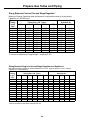
Sizing Between First and Second Stage Regulator*
Maximum Propane Capacities listed are based on 2 psig pressure drop at 10 psig setting.
Capacities in 1,000 BTU/hour.
Pipe or
Nominal Pipe Size
Tubing
Tubing Size, O.D. Type L
Schedule 40
Length,
3/8"
1/2"
5/8"
3/4"
7/8"
1/2"
3/4"
Feet
10
730
1,700
3,200
5,300
8,300
3,200
7,500
20
500
1,100
2,200
3,700
5,800
2,200
4,200
30
400
920
2,000
2,900
4,700
1,800
4,000
40
370
850
1,700
2,700
4,100
1,600
3,700
50
330
770
1,500
2,400
3,700
1,500
3,400
60
300
700
1,300
2,200
3,300
1,300
3,100
80
260
610
1,200
1,900
2,900
1,200
2,600
100
220
540
1,000
1,700
2,600
1,000
2,300
125
200
490
900
1,400
2,300
900
2,100
150
190
430
830
1,300
2,100
830
1,900
175
170
400
780
1,200
1,900
770
1,700
200
160
380
730
1,100
1,800
720
1,500
To convert to capacities at 15 psig settings - multiply by 1.130
To convert to capacities at 5 psig settings - multiply by 0.879
Sizing Between Single or Second Stage Regulator and Appliance*
Maximum Propane Capacities Listed are Based on 1/2" W.C. pressure drop at 11" W.C. setting.
Capacities in 1,000 BTU/hour.
Nominal Pipe Size
Pipe or
Tubing
Tubing Size, O.D. Type L
Schedule 40
Length,
3/8"
1/2"
5/8"
3/4"
7/8" 1-1/8" 1/2"
3/4"
1"
1-1/4" 1-1/2"
Feet
10
39
92
199
329
501
935
275
567
1,071 2,205 3,307
20
26
62
131
216
346
630
189
393
732
1,496 2,299
30
21
50
107
181
277
500
152
315
590
1,212 1,858
40
19
41
90
145
233
427
129
267
504
1,039 1,559
50
18
37
79
131
198
376
114
237
448
913
1,417
60
16
35
72
121
187
340
103
217
409
834
1,275
80
13
29
62
104
155
289
89
185
346
724
1,066
100
11
26
55
90
138
255
78
162
307
630
976
125
10
24
48
81
122
224
69
146
275
567
866
150
9
21
43
72
109
202
63
132
252
511
787
200
8
19
39
66
100
187
54
112
209
439
665
250
8
17
36
60
93
172
48
100
185
390
590
*Data in accordance with NFPA pamphlet NO. 54
24
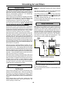
Circulating Air and Filters
NOTE: An undersized opening will cause reduced
airflow.
Ductwork Sizing
Duct systems and register sizes must be properly designed for the CFM and external static pressure rating of
the furnace. Ductwork should be designed in accordance
with the recommended methods of “Air Conditioning
Contractors of America” Manual D.
A duct system must be installed in accordance with Standards of the National Board of Fire Underwriters for the
Installation of Air Conditioning, Warm Air Heating and
Ventilating Systems. Pamphlets No. 90A and 90B.
A closed return duct system must be used, with the return
duct connected to the furnace. NOTE: Ductwork must
never be attached to the back of the furnace. Supply
and return connections to the furnace may be made with
flexible joints to reduce noise transmission. To prevent the
blower from interfering with combustion air or draft when a
central return is used, a connecting duct must be installed
between the unit and the utility room wall. A room, closet,
or alcove must not be used as a return air chamber.
When the furnace is used in connection with a cooling unit,
the furnace should be installed in parallel with or on the
upstream side of the cooling unit to avoid condensation in
the heating element. With a parallel flow arrangement, the
dampers or other means used to control the flow of air must
be adequate to prevent chilled air from entering the furnace
and, if manually operated, must be equipped with means
to prevent operation of either unit unless the damper is in
the full heat or cool position.
Units with an air delivery of less than 1800 CFM should
either use the bottom return or one-side return.
Units with an air delivery of 1800 CFM or higher must either
use a two-side return combination or a one-side return and
one bottom return combination. These combinations provide proper airflow through the unit.
To ensure proper unit performance follow the filter sizes
given in the Specifications Sheet.
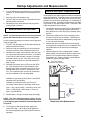
Upright Installations
Depending on the installation and/or customer preference,
differing filter arrangements can be applied. Filters can be
installed in the central return register, the bottom of the
blower compartment, a side panel external filter rack kit, or
inside the side panel. As an alternative a media air filter or
electronic air cleaner can be used as the requested filter.
Review and follow the filter sizes given in the Specifications Sheet to ensure proper unit performance. The
following figures show possible filter locations.
AIR FLOW
SIDE RETURN
INTERNAL FILTER
RETENTION
(EITHER SIDE)
F IL T E R
When the furnace is installed without a cooling coil, it is
recommended that a removable access panel be provided
in the outlet air duct. This opening shall be accessible
when the furnace is installed and shall be of such a size that
the heat exchanger can be viewed for visual light inspection or such that a sampling probe can be inserted into the
airstream. The access panel must be made to prevent air
leaks when the furnace is in operation.
SIDE RETURN
EXTERNAL FILTER
RACK KIT
(EITHER SIDE)
F IL T E R
F IL T E R
CENTRAL
RETURN
GRILLE
F IL T E R
When the furnace is heating, the temperature of the return
air entering the furnace must be between 55°F and 100°F.
When a furnace is installed so that supply ducts carry air
circulated by the furnace to areas outside the space
containing the furnace, the return air shall also be handled
by a duct sealed to the furnace casing and terminating
outside the space containing the furnace.
Horizontal Installations
Filters
Filters must be installed in either the central return register
or in the return air duct work.
READ THIS SECTION BEFORE INSTALLING THE RETURN
AIR DUCTWORK
Refer to the Specification Sheet for recommended minimum filter sizes.
Possible Filter Locations
Filters must be used with this furnace. Discuss filter maintenance with the building owner. Filters do not ship with
this furnace, but must be provided by the installer. Filters
must comply with UL900 or CAN/ULCS111 standards. If
the furnace is installed without filters, the warranty will be
voided.
Use a straight edge to scribe lines, connect the guide
dimples located on the side return cutout locations. Cut
out the opening on these lines.
25
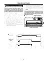
Startup Adjustments and Measurements
Furnace must have a 115 VAC power supply properly connected and grounded. Proper polarity must be maintained for
correct operation. An interlock switch prevents furnace operation if the blower door is not in place. Keep the blower access
door in place except for inspection and maintenance.
This furnace is also equipped with a self-diagnosing electronic control module. In the event a furnace component is not
operating properly, the control module LED will flash on and off in a factory-programmed sequence, depending on the
problem encountered. This light can be viewed through the observation window in the blower access door. Refer to the
Troubleshooting Chart for further explanation of the lighting codes.
On new installations, or if a functional part such as the gas valve, pressure switch, or limit control has been replaced, verify
that the furnace is operating properly after servicing.
Check furnace operation as outlined in the following instructions. If any sparking, odors, or unusual noises are
encountered, shut off electrical power and recheck for wiring errors, or obstructions in or near the blower motors. Various
shipping materials must be removed before the blower motor is operated. In addition to the following startup adjustments
and measurements items, refer to further information in Operational Checks.
Furnace Operation
Purge gas lines of air prior to startup. Be sure not purge lines into an enclosed burner compartment.
Check for leaks using an approved chloride-free soap and water solution, an electronic combustible gas detector, or other
approved method. Verify that all required kits (propane gas, high altitude, etc.) have been appropriately installed.
NOTE: An interlock switch prevents furnace operation if the blower door is not in place. Keep the blower access
doors in place except for inspection and maintenance.
FURNACE STARTUP
10. Turn on the electrical power to the furnace.
1. Close the manual gas shut-off valve external to the
furnace.
11. Set the room thermostat to the desired temperature.
2. Turn off the electrical power to the furnace.
NOTE: There is an approximate 30 second delay
between thermostat energizing and burner firing.
3. Set the room thermostat to the lowest possible setting.
FURNACE SHUTDOWN
4. Remove the burner compartment door.
1. Set the thermostat to the lowest setting.
NOTE: This furnace is equipped with an electronic
ignition device which automatically lights the burner.
Do not try to light the burner by hand.
2. Turn off the electrical power supply to the furnace.
3. Turn the gas control knob clockwise
to the
OFF position. The knob should turn easily. Do not
use excessive force.
5. Turn the gas control knob clockwise
to the
OFF position. Note: The knob should turn easily.
Do not use excessive force.
4. Close manual gas shutoff valve external to the furnace and replace burner compartment door.
High Manifold
Regulator Adjustment
Screw (Under Cap)
6. Wait five minutes then smell for gas. Be sure check
near the floor as some types of gas are heavier than
air.
PM
C
HI
7. If you smell gas after five minutes, immediately follow
the instructions on page 4 of this manual. If you do
not smell gas after five minutes:
Inlet
Outlet
OFF
Turn the gas control knob counterclockwise
to the ON position. The knob should turn easily. Do
not use excessive force.
ON
Inlet Pressure Tap
Low Manifold
(Side of Valve)
Regulator Adjustment
Gas Valve
Screw (Under Cap)
Control Knob
8. Replace the burner compartment door.
9. Open the manual gas shut-off valve external to the
furnace.
Outlet (Manifold)
Pressure Tap
(Side of Valve)
White-Rodgers Model 36E96
26
Startup Adjustments and Measurements
Measure Gas Supply Pressure
4. Measure furnace gas supply pressure with burners
firing. Supply pressure must be within the range
specified in the “Inlet Gas Supply Pressure” table .
If supply pressure differs from the table, make necessary
adjustments to pressure regulator, gas piping size, etc.,
and/or consult with local gas utility.
CAUTION
To prevent unreliable operation or equipment
damage, the inlet gas supply pressure must be as
specified on the unit rating plate with all other
household gas fired appliances operating.
5. Turn OFF gas to furnace at the manual shutoff valve
and disconnect manometer. Reinstall plug before
turning on gas to furnace.
6. Turn OFF any unnecessary gas appliances started in
step 3.
The line pressure supplied to the gas valve must be within
the range specified in the “Inlet Gas Supply Pressure”
table.
Natural Gas
Propane Gas
Measure and Adjust Gas Manifold Pressure
Inlet Gas Supply Pressure
Minimum:5.0" W.C. Maximum :10.0" W.C.
Minimum:11.0" W.C. Maximum :13.0" W.C.
CAUTION
Measure the supply pressure at the gas valve inlet pressure tap or at a hose fitting installed in the gas piping drip
leg. The supply pressure must be measured with the
burners operating. To measure the gas supply pressure,
use the following procedure.
To prevent unreliable operation or equipment
damage, the gas manifold pressure must be as
specified on the unit rating plate. Only minor
adjustments should be made by adjusting the gas
valve pressure regulator.
1. Turn OFF gas to furnace at the manual gas shutoff
valve external to the furnace.
Only small variations in gas pressure should be made by
adjusting the gas valve pressure regulator. The manifold
pressure must be measured with the burners operating.
To measure and adjust the manifold pressure, use the
following procedure.
2. Connect a calibrated water manometer (or appropriate gas pressure gauge) at either the gas valve inlet
pressure tap or the gas piping drip leg.
NOTE: At either location, a hose fitting must be installed
prior to making the hose connection.
1. Turn OFF gas to furnace at the manual gas shutoff
valve external to the furnace.
Gas Line
2. Connect a calibrated water manometer (or appropriate gas pressure gauge) at the gas valve outlet pressure tap (refer to gas valve figure in previous
section).
Gas
Shutoff
Valve
3. Turn ON the gas supply and operate the furnace.
Gas Line
To Furnace
4. Measure gas manifold pressure with burners firing.
Adjust manifold pressure using the table below.
Open To
Atmosphere
Manifold Gas Pressure
Gas
Range
Drip Leg Cap
With Fitting
Natural
Manometer Hose
Propane
Manometer
Low Stage
High Stage
Low Stage
High Stage
1.6 - 2.2" w.c.
3.0 - 3.6" w.c.
5.7 - 6.3" w.c.
9.7 - 10.3" w.c.
Nominal
1.9" w.c.
3.5" w.c.
6.0" w.c.
10.0" w.c.
The final manifold pressure must not vary more
than ± 0.3 “ w.c. from the above specified pressures. Any
necessary major changes in gas flow rate should be made
by changing the size of the burner orifice.
Measuring Inlet Gas Pressure
(Alternate Method)
3. Turn ON the gas supply and operate the furnace and
all other gas consuming appliances on the same gas
supply line.
5. To adjust the gas valve pressure regulator, remove
the regulator cap.
27
Startup Adjustments and Measurements
Measure and Adjust Temperature Rise
6. Turn the adjustment screw clockwise to increase the
pressure, or counterclockwise to decrease the pressure.
Air temperature rise is the temperature difference between
supply and return air. Temperature rise must be within the
range specified on the unit rating plate. An incorrect temperature rise could cause condensing in or overheating of
the heat exchanger. An airflow and temperature rise table
is provided in the specification sheet. Determine and
adjust temperature rise as follows:
7. Securely replace the regulator cap.
8. Turn OFF gas to furnace at the manual shutoff valve
and disconnect manometer.
9. Reinstall gas valve outlet pressure tap plug before
turning on gas to furnace.
1. Operate furnace with burners firing for approximately
ten minutes. Ensure all registers are open and all
duct dampers are in their final (fully or partially open)
position.
Measure Natural Gas Input Rate
NOTE: The gas input rate to the furnace must never be
greater than that specified on the unit rating plate.
2. Place thermometers in the return and supply ducts
as close to the furnace as possible. Thermometers
must not be influenced by radiant heat by being able
to “see” the heat exchanger.
Use the following procedure to measure natural gas input
using the gas meter:
3. Subtract the return air temperature from the supply
air temperature to determine the air temperature rise.
Allow adequate time for thermometer readings to
stabilize.
1. Turn OFF the gas supply to all other gas-burning appliances except the furnace.
2. While the furnace is operating, time and record one
complete revolution of the smallest gas meter dial.
4. Adjust temperature rise by adjusting the circulator
blower speed. Increase blower speed to reduce temperature rise. Decrease blower speed to increase
temperature rise. Refer to Adjust Circulator Blower
Speeds for speed changing details.
3. Calculate the number of seconds per cubic foot (sec/
ft3) of gas being delivered to the furnace. If the dial is
a one cubic foot dial, divide the number of seconds
recorded in step 2 by one. If the dial is a two cubic
foot dial, divide the number of seconds recorded in
step 2 by two.
HEAT EXCHANGER
RADIATION "LINE OF SIGHT"
4. Calculate the furnace input in BTUs per hour (BTU/
hr). Input equals the sum of the installation’s gas
heating value and a conversion factor (hours to seconds) divided by the number of seconds per cubic
foot. The measured input must not be greater than
the input indicated on the unit rating plate.
SUPPLY
AIR
TSUPPLY
Installation’s gas heating (HTG) value: 1,000 BTU/ft3
(Obtained from gas supplier)
Installation’s seconds per cubic foot: 34 sec/ ft3
RISE =
Conversion Factor (hours to seconds): 3600 sec/hr
TSUPPLY - TRETURN
Input = (Htg. value x 3600) ÷ seconds per cubic foot
TRETURN
Input = (1,000 BTU/ft3 x 3600 sec/hr) ÷ 34 sec/ ft3
Input = 106,000 BTU/hr
RETURN
AIR
5. Repeat steps 1 through 3 on high stage (2nd stage).
NOTE: The final manifold pressure cannot vary by
more than ± 0.3” w.c. from the specified setting. Consult
your local gas supplier if additional input rate adjustment
is required.
Temperature Rise Measurement
6. Turn ON gas to and relight all other appliances
turned off in step 1. Be certain that all appliances
are functioning properly and that all pilot burners are
operating.
28
Startup Procedure and Adjustment
4. Locate the blower speed selection DIP switches on the
integrated control module. Select the desired “cooling” speed tap by positioning switches 1 and 2 appropriately. Select the desired “adjust” tap by positioning
switches 3 and 4 appropriately. Refer to the following
figure for switch positions and their corresponding
taps. Turn off power to furnace for a minimum of 10
seconds, allowing motor to reset and recognize new
speed selection. Turn on power to furnace. Verify
CFM by counting the number of times the green CFM
LED blinks.
5. Select the heating speed from the heating speed chart
in the specification sheet for your model. The adjust
setting (already established by the cooling speed
selection) determines which set of speeds are available. The selected speed must provide a temperature
rise within the rise range listed with the particular
model.
Example: The 70 kBtu is set for 990 CFM on cooling,
the “ADJUST” is set to “-” (minus). The
four heating speeds available are “A Minus”, “B Minus”, “C Minus”, and “D Minus”.
“B Minus” has a rise of 56°F for both
stages which is within the 30-60°F rise
range for the 70 kBtu. This setting will
keep electrical consumption to a minimum. Set the “Heat” speed DIP switches
to “A”.
6. Select the desired “heating” speed tap by positioning
switches 7 and 8 appropriately. Refer to figure above.
Turn off power to furnace for a minimum of 10 seconds,
allowing motor to reset and recognize new speed
selection. Turn on power to furnace. Verify selected
CFM by counting the green CFM LED blinks.
Adjust Circulator Blower Speeds
WARNING
To avoid death or personal injury due to electrical
shock, turn off power to the furnace before changing
speed taps.
All furnaces are shipped with heating speed set at “B” and
cooling speed set at “D”. Use the following procedure to
select the heating and cooling speed needed for your unit.
Use the CFM LED (green), adjacent to the integrated
control module fuse to verify airflow quantity. The green
CFM LED blinks once for each 100 CFM of airflow.
1. Determine the tonnage of the cooling system installed
with the furnace. If the cooling capacity is in BTU/hr
divide it by 12,000 to convert capacity to TONs.
Example:Cooling Capacity of 30,000 BTU/hr.
30,000/12,000 = 2.5 Tons
2. Determine the proper air flow for the cooling system.
Most cooling systems are designed to work with air
flows between 350 and 450 CFM per ton. Most manufacturers recommend an air flow of about 400 CFM per
ton.
Example: 2.5 tons X 400 CFM per ton = 1000 CFM
The cooling system manufacturer’s instructions must be
checked for required air flow. Any electronic air cleaners
or other devices may require specific air flows, consult
installation instructions of those devices for requirements.
In general lower heating speeds will: reduce electrical
consumption, lower operating sound levels of the blower,
and increase the outlet air temperature delivered to the
home. The speeds available allow the blower performance to be optimized for the particular homeowner’s
needs.
3. Knowing the furnace model, locate the high stage
cooling air flow charts in the specification sheet. Look
up the cooling air flow determined in step 2 and find the
required cooling speed and adjustment setting.
Example: A 70 kBtu furnace is to be installed with a
2.5 ton air conditioning system. The air
flow needed is 1000 CFM. Using the cooling speed chart for the 70 kBtu furnace,
find the airflow closest to 1000 CFM. A
cooling airflow of 990 CFM can be attained by setting the cooling speed to “C”
and the adjustment to “-” (minus).
NOTE: Continuous Fan Speed will be
56% of high stage cooling.
29
Startup Procedure and Adjustment
8 7
Cooling
Speed
Tap A
Normal
8 7
Cooling
Speed
Tap B
O
F
F
4 3 2
8 7
4 3 2 1
8 7
O
F
F
4
8 7
O O
F N
F
4 3 2 1
Adjust Blower Heat Off Delay
*
O
F
F
1
O
F
F
3 2 1
The integrated control module provides a selectable heat
off delay function. The heat off delay period may be set to
60, 90, 120, 180 seconds using the DIP switches or jumper
provided on the control module. The delay is factory
shipped at 90 seconds but may be changed to suit the
installation requirements and/or homeowner preference.
Refer to the following figures for switch positions and
corresponding delay times.
+ (Plus)
Adjust
8 7
Cooling
Speed
Tap C
Cooling
Speed
Tap D
4 3 2 1
O O
F N
F
4 3 2 1
- (Minus)
Adjust
*
8 7
O O
N F
F
4 3 2 1
Cooling Speed Taps
(* indicates factory setting)
O O
N F
F
Adjust Taps
O O
N N
(* indicates factory setting)
Heating
Speed
Tap A
Heating
Speed
Tap B
Heating
Speed
Tap C
Heating
Speed
Tap D
*
ON
ON
3
2
1
Heat Off
Delay
60 Seconds
ON
OFF
3
2
1
Heat Off *
Delay
90 Seconds
8 7
4 3 2 1
O
F
F
8
O
F
F
7
4 3 2 1
OFF
ON
3
2
1
Heat Off
Delay
120 Seconds
O O
F N
F
8 7
4 3 2 1
OFF
OFF
3
2
1
Heat Off
Delay
180 Seconds
O O
N F
F
8 7
Heat Off Delay
(* indicates factory setting)
4 3 2 1
Heat Off Delay Switches
O O
N N
Heating Speed Taps
(* indicates factory setting)
30
Normal Sequence of Operation
Power Up
The normal power up sequence is as follows:
• 115 VAC power applied to furnace.
• Integrated control module performs internal checks.
• Integrated control module flashes LED one time.
• Integrated control module monitors safety circuits continuously.
• Furnace awaits call from thermostat.
Heating Mode
The normal operational sequence in heating mode is as follows:
• R and W1 (or R and W1/W2) thermostat contacts
close, initiating a call for heat.
• Integrated control module performs safety circuit
checks.
• Induced draft blower is energized on high speed for a
10-second prepurge. Humidifier terminals are energized with induced draft blower.
• Induced draft blower steps to low speed following
prepurge. Low stage pressure switch contacts are
closed.
• Igniter warm up begins upon step to low speed and
presence of closed low stage pressure switch contacts.
• Gas valve opens at end of igniter warm up period,
delivering gas to burners and establishing flame.
• Integrated control module monitors flame presence.
Gas valve will remain open only if flame is sensed.
• If the thermostat call is for low heat, gas valve and
induced draft blower will continue on low stage. If the
call is for high heat, the gas valve and induced draft
blower will change to high stage.
• Circulator blower is energized on the appropriate heat
speed following a fixed thirty second blower on delay.
The circulator blower requires 30 seconds to ramp up
to full speed. Electronic air cleaner terminals are
energized with circulator blower.
• Furnace is now operating on the specified stage called
for by the two-stage thermostat.
• Furnace runs, integrated control module monitors safety
circuits continuously.
• If the two-stage thermostat changes the call from low
•
•
•
•
•
•
•
•
31
heat to high heat, the integrated control module will
immediately switch the induced draft blower, gas valve,
and circulator blower to their high stage settings.
If the two-stage thermostat changes the call from high
heat to low heat, the control will immediately switch the
induced draft blower and gas valve to their low stage
settings. The circulator blower will remain on high
heating speed for thirty seconds before switching to
the low heat circulating speed.
R and W1 (or R and W1/W2) thermostat contacts
open, completing the call for heat.
Gas valve closes, extinguishing flame.
Induced draft blower is de-energized following a fifteen
second post purge. Humidifier terminals are de-energized.
Circulator blower continues running for the selected
heat off delay period (60, 90, 120, or 180 seconds).
The speed run during this period depends on the last
heat call provided by the thermostat.
If the last call for heat was a call for low heat, the air
circulator motor will run on low heat speed for the
duration of the heat off delay period (60, 90, 120, or 180
seconds).
If the last call for heat was a call for high heat, the air
circulating motor will run on the high heating speed for
thirty seconds and then switch to the low heating
speed for the balance of the heat off delay period (30,
60, 90, or 150 seconds).
Circulator blower and electronic air cleaner terminals
are de-energized
Circulator blower ramps down to OFF during the 30
seconds following the heat off delay period.
Furnace awaits next call from thermostat.
Normal Sequence of Operation
Cooling Mode
Fan Only Mode
The normal operational sequence in cooling mode is as
follows:
The normal operational sequence in fan only mode is as
follows:
• R and YLO/G or Y/G thermostat contacts close, initiat-
• R and G thermostat contacts close, initiating a call for
ing a call for cool.
• Integrated control module performs safety circuit
checks.
• Outdoor fan and compressor are energized to their
appropriate speed.
• Circulator blower is energized on the appropriate cool
speed following a fixed five second on delay. The
circulator blower requires 30 seconds to ramp up to full
speed. Electronic air cleaner terminals are energized
with circulator blower.
• Furnace circulator blower and outdoor cooling unit run
their appropriate speed, integrated control module
monitors safety circuits continuously.
• R and YLO/G or Y/G thermostat contacts open, completing the call for cool.
• Outdoor fan and compressor are de-energized.
• Circulator blower continues running for a fixed 45second cool off delay period. The speed run during
this period depends on the last cooling call from the
thermostat. If the call was for low cool, the blower will
operate at 88% of low cool speed. If call was for high
cool, blower operate at 88% of high cool speed.
• Electronic air cleaner terminals and circulator blower
are de-energized.
• Furnace awaits next call from thermostat.
•
•
•
•
•
•
32
fan.
Integrated control module performs safety circuit
checks.
Circulator blower is energized on continuous fan speed
(56% of high stage cooling) following a five (5) second
delay. Electronic air cleaner terminals are energized.
Circulator blower runs, integrated control module monitors safety circuits continuously.
R and G thermostat contacts open, completing the call
for fan.
Circulator blower is de-energized. Electronic air cleaner
terminals are de-energized.
Furnace awaits next call from thermostat.
Timing Charts For Normal Heating Operation
Example 1: Continuous Call For Low Stage Heat Only
High
Low
Off
Gas Valve
On
Off
Igniter
On
Off
Pressure
Switches
Induced Draft
Blower
Thermostat
(Call for Heat)
PS2 Closed
PS1 Closed
Open
High
Low
Off
High
Low
Off
0
10
30
33
34
{
Circulator
Blower
4-second
maximum trial
for ignition
period
64
94
0
15
30
60, 90
120, or
180
90, 120,
150, or
210
30
60, 90
120, or
180
90, 120,
150, or
210
Time (sec)
Example 2: Continuous Call For High Stage Heat Only
Gas Valve
Igniter
Pressure
Switches
High
Low
Off
High
Low
Off
On
Off
PS2 Closed
PS1 Closed
Open
Induced Draft
Blower
High
Low
Off
Thermostat
(Call for Heat)
High
Low
Off
0
10
30
33
34
{
Circulator
Blower
4-second
maximum trial
for ignition
period
64 94
Time (sec)
33
0
15
Timing Charts for Normal Heating Operation
Example 3: Initial Call For Low Heat, Change In Call To High Heat
Call Change to High Heat
Gas Valve
Igniter
Pressure
Switches
High
Low
Off
High
Low
Off
On
Off
PS2 Closed
PS1 Closed
Open
Induced Draft
Blower
High
Low
Off
Thermostat
(Call For Heat)
High
Low
Off
0
10
30
33
34
{
Circulator
Blower
4-second
maximum trial
for ignition
period
64 94
0
15
Time (sec)
30
60, 90
120, or
180
90, 120,
150, or
210
Example 4: Initial Call For High Heat, Subsequent Call To Low Heat
Call Change to Low Heat
30 Seconds After Call Change to Low Heat
Gas Valve
Igniter
Pressure
Switches
High
Low
Off
High
Low
Off
On
Off
PS2 Closed
PS1 Closed
Open
Induced Draft
Blower
High
Low
Off
Thermostat
(Call For Heat)
High
Low
Off
0
10
30
33
34
{
Circulator
Blower
4-second
maximum trial
for ignition
period
64 94
Time (sec)
34
0
15
60, 90 90, 120,
120, or 150, or
180
210
Timing Charts for Normal Cooling Operation
Example 1: Continuous Call For Low Stage Cooling Only
Circulator
Blower
Outdoor Fan
And
Compressor
Thermostat
(Call For Cool)
High
Low
Off
(88% of Low)
High
Low
Off
High
Low
Off
0
5
Time (sec)
35
0
45
Example 2: Continuous Call For High Stage Cooling Only
Circulator
Blower
Outdoor Fan
And
Compressor
Thermostat
(Call For Cool)
High
Low
Off
(88% of High)
High
Low
Off
High
Low
Off
0
5
Time (sec)
35
0
Timing Chart for Normal Fan Operation
Circulator
Blower
Thermostat
(Call For Fan)
On
Off
On
Off
0
Time (sec)
5
35
0
45
Operational Checks
These checks establish that the primary limit control is functioning and will respond to a restriction in the return air, or a
circulator blower failure. If the primary limit control does not function during this test, the cause must be determined and
corrected.
WARNING
To prevent personal injury or death, do not remove any internal compartment covers or attempt any adjustment.
Electrical components are contained in both compartments. Contact a qualified service agent at once if an
abnormal flame appearance should develop.
WARNING
To prevent death, personal injury or property damage due to fire, follow these directions for the auxiliary limit
control. If the auxiliary limit control opens, it may be reset one time only.
WARNING
To prevent death, personal injury, property damage or premature failure of heat exchanger, do not adjust the
primary limit control (factory set).
Burner Flame
Auxiliary Limit
The burner flames should be inspected with the burner
compartment door installed. A sight glass is provided for
inspection purposes. Flames should be stable, quiet, soft,
and blue (dust may cause orange tips but they must not be
yellow). Flames should extend directly outward from the
burners without curling, floating, or lifting off. Flames must
not impinge on the sides of the heat exchanger firing tubes.
A manual reset limits are located on or near the blower. To
access this auxiliary limit, disconnect the electrical power
and remove the blower door. If the limit control opens, the
air circulation blower will run continuously. The diagnostic
light will flash four times. These symptoms are identical to
a trip of the primary limit control.
The auxiliary limit control is designed to prevent furnace
operation in case of main blower failure on horizontal
installations. It may also open if the power supply is
interrupted while the furnace is firing.
The auxiliary limit control is suitable for both horizontal right
and horizontal left installations. Regardless of airflow direction, it does not need to be relocated.
(SERVICER’S NOTE: If it becomes necessary to slide the
blower assembly out of the furnace, the auxiliary limit
control should be removed first. After the blower assembly
is reinstalled, the auxiliary limit must be reinstalled.)
Check the burner flames for:
1. Good adjustment
2. Stable, soft and blue
3. Not curling, floating, or lifting off.
Burner Flame
36
Operational Checks
High or Primary Limit
3. Remove the return air blockage to clear overheating
condition. After an acceptable temperature is
reached during the cool down period, the limit control
will reset and allow the furnace to resume normal operation.
The primary limit control guards against overheating resulting from insufficient conditioned air passing over the
heat exchanger. If the primary limit control does not
function during this test, the cause must be determined and
corrected. Function of this control should be verified by
gradually blocking the furnace return air after the furnace
has been operating (burners firing) for approximately 15
minutes. Check the control as follows:
These checks establish that the primary limit control is
functioning and will respond to a restriction in the return air,
or a circulator blower failure. If the primary limit control
does not function during this test, the cause must be
determined and corrected.
1. Allow the furnace to operate with burners firing continuously for approximately 15 minutes.
Primary Limit Control
2. Gradually block the return air to furnace. Remove
airflow blockage when limit control is activated and
turns off burners. Airflow blockage causes unit overheating and will produce the following reactions:
• The gas valve to close and extinguish flame,
• The induced draft blower to deenergized after a
fifteen second postpurge, and
• The circulator blower to remain energized continuously until limit control resets.
Primary Limit Control
Indoor Fan
On
Off
Outdoor Fan
And
Compressor
On
Off
Thermostat
On
Off
Seconds
0
5
0
37
45
Safety Circuit Description
A number of safety circuits are employed to ensure safe and proper furnace operation. These circuits serve to control
any potential safety hazards and serve as inputs in the monitoring and diagnosis of abnormal function. These circuits
are continuously monitored during furnace operation by the integrated ignition control.
Rollout Limit
Integrated Ignition Control
The rollout limit controls are mounted on the burner/
manifold assembly and monitor the burner flame. They are
normally-closed (electrically), manual-reset, temperatureactivated sensors. These limits guard against burner
flames not being properly drawn into the heat exchanger.
The integrated ignition control is an electronic device
which controls all furnace operations. Responding to the
thermostat, the module initiates and controls normal furnace operation, and monitors and addresses all safety
circuits. If a potential safety concern is detected, the
module will take the necessary precautions and provide
diagnostic information through an LED.
Pressure Switches
Primary Limit
The pressure switches are normally-open (closed during
operation), single-pole single-throw, negative air pressure-activated switches. They monitor the airflow (combustion air and flue products) through the heat exchanger
via pressure taps located on the induced draft blower and
the coil front cover. These switches guard against insufficient airflow (combustion air and flue products) through the
heat exchanger and/or blocked condensate drain conditions.
The primary limit control is located on the partition panel
and monitors heat exchanger compartment temperatures.
It is a normally-closed (electrically), automatic reset, temperature-activated sensor. The limit guards against the
overheating as a resulting of insufficient conditioned air
passing over the heat exchanger.
Auxiliary Limit
Flame Sensor
The auxiliary limit controls are located on or near the
circulator blower and monitors heat exchanger compartment temperatures. They are a normally-closed (electrically), manual-reset, temperature activated sensor. These
limits guard against overheating as a result of insufficient
conditioned air passing over the heat exchanger.
The flame sensor is a probe mounted to the burner/
manifold assembly which uses the principle of flame rectification to determine the presence or absence of flame.
Burner Box
This furnace must use indoor air for combustion. It is not a
direct vent furnace, and it cannot be installed as a direct
vent furnace. The burner box is present only to reduce the
burner sound transmission.
38
Troubleshooting
Electrostatic Discharge (ESD) Precautions
NOTE: Discharge body’s static electricity before touching unit. An electrostatic discharge can adversely affect
electrical components.
Use the following precautions during furnace installation and servicing to protect the integrated ignition control from
damage. By putting the furnace, the control, and the person at the same electrostatic potential, these steps will help avoid
exposing the integrated ignition control to electrostatic discharge. This procedure is applicable to both installed and
uninstalled (ungrounded) furnaces.
1. Disconnect all power to the furnace. Do not touch the integrated ignition control or any wire connected to the control prior to discharging your body’s electrostatic charge to ground.
2. Firmly touch a clean, unpainted, metal surface of the furnaces near the control. Any tools held in a person’s hand
during grounding will be discharged.
3. Service integrated ignition control or connecting wiring following the discharge process in step 2. Use caution not
to recharge your body with static electricity; (i.e., do not move or shuffle your feet, do not touch ungrounded objects, etc.). If you come in contact with an ungrounded object, repeat step 2 before touching control or wires.
4. Discharge your body to ground before removing a new control from its container. Follow steps 1 through 3 if installing the control on a furnace. Return any old or new controls to their containers before touching any ungrounded object.
Furnace Lockout
Diagnostic Chart
Furnace lockout results when a furnace is unable to
achieve ignition after three attempts, or when it has lost
flame five times during a single call for heat. It is characterized by a non-functioning furnace and a one flash
diagnostic LED code. If the furnace is in “lockout”, it will (or
can be) reset in any of the following ways.
WARNING
To avoid electrical shock, injury or death, disconnect
electrical power before performing any service or
maintenance.
1. Automatic reset. The integrated ignition control will
automatically reset itself and attempt to resume normal operations following a two hour lockout period.
For assistance in determining the source of unit operational problems, refer to the troubleshooting chart on the
following pages The red diagnostic LED blinks to assist in
troubleshooting the unit. The number of blinks refers to a
specific fault code.
2. Manual power interruption. Interrupt 115 volt power
to the furnace for 0 - 30 seconds.
3. Manual thermostat cycle. Lower the thermostat so
that there is no longer a call for heat then reset to
previous setting. Interrupt thermostat signal to the
furnace for 0 - 30 seconds.
NOTE: If the condition which originally caused the
lockout still exists, the control will return to lockout.
Refer to Diagnostic Chart section for aid in determining
the cause.
39
Troubleshooting Chart
Symptoms of Abnormal
Operation
Associated
LED Code2
• Furnace fails to operate.
• Integrated control module
diagnostic LED provides
no signal.
NONE
Fault Description(s)
• No 115 volt power to • Manual disconnect switch
furnace, or no 24 volt OFF, door switch open, or
power to integrated
24 volt wires improperly
control module.
connected or loose.
• Blown fuse or circuit • Blown fuse or circuit
breaker.
breaker.
• No signal from
thermostat.
• Furnace fails to operate.
ON
• Integrated control module
diagnostic LED is lit
continuously.
CONTINUOUS
Possible Causes
• Improper thermostat
connection or setting.
Corrective Action
• Assure 115 and 24 volt
power to furnace
integrated control module.
• Check integrated control
module fuse (3A).
Replace if necessary.
• Check for possible shorts
in 115 and 24 volt circuits.
Repair as necessary.
• Turn power OFF prior
to repair.
• Turn power OFF prior
to repair.
• Read precautions in
“Electrostatic Discharge” section of
manual.
• Integrated control
module has an
internal fault.
• Integrated control module
has an internal fault.
• Replace bad integrated
control module.
• Furnace lockout due
to an excessive
number of ignition
“retries” (3 total) or
“recycles (5 total)1.
• Failure to establish flame.
Cause may be no gas to
burners, front cover
pressure switch stuck open,
bad igniter or igniter
alignment, improper orifices,
or coated/oxidized or
improperly connected flame
sensor.
• Locate and correct gas
interruption.
• Check front cover
pressure switch
operation (hose, wiring,
contact operation).
Correct if necessary.
• Replace or realign
igniter.
• Check flame sense
signal. Sand sensor if
coated and/or oxidized.
• Check flue piping for
blockage, proper
length, elbows, and
termination.
• Verify proper induced
draft blower performance.
ON
• Furnace fails to operate.
• Integrated control module
diagnostic LED is
flashing ONE (1) flash.
1
1 FLASH
• Loss of flame after establishment. Cause may be
interrupted gas supply, lazy
burner flames (improper gas
pressure or restriction in flue
and/or combustion air
piping), front cover pressure
switch opening, or improper
induced draft blower
performance.
• Furnace fails to operate.
• Integrated control module
diagnostic LED is
flashing TWO (2) flashes.
2
2 FLASHES
• Induced draft blower
cycles ON for one minute
3
and OFF for three
minutes with no further
furnace operation.
3 FLASHES
• Integrated control module
diagnostic LED is
flashing THREE (3)
flashes.
• Pressure switch
circuit is closed.
• Induced draft
blower is not
operating.
• Induced draft blower
pressure switch contacts
sticking.
• Shorts in pressure switch
circuit.
• Low stage pressure • Pressure switch hose
switch circuit does
blocked, pinched or
not close in
connected improperly.
response to
• Blocked flue and/or inlet air
induced draft
pipe, blocked drain system,
blower operation.
or weak induced draft
blower.
• Incorrect low stage pressure
switch setpoint or malfunctioning switch contacts.
• Loose or improperly
connected wiring.
1
Integrated control module will automatically attempt to reset from lockout after one hour.
40
Cautions and Notes
• Replace integrated
control module fuse
with 3A automotive
fuse.
• Improper thermostat
connection or setting.
• Turn power OFF prior
to repair.
• Igniter is fragile, handle
with care.
• Sand flame sensor with
emery cloth.
• See “Vent/Flue Pipe”
section for piping
details.
• Replace induced draft
blower pressure switch.
• Repair short.
• Inspect pressure
switch hose. Repair, if
necessary,
• Inspect flue and/or inlet
air piping for blockage,
proper length, elbows,
and termination. Check
drain system. Correct
as necessary.
• Correct low stage
pressure switch
setpoint or contact
motion.
• Tighten or correct
wiring connection.
• Turn power OFF prior
to repair.
• Replace pressure
switch with proper
replacement part.
• Turn power OFF prior
to repair.
• Replace pressure
switch with proper
replacement part.
Troubleshooting Chart
Symptoms of Abnormal
Operation
• Circulator blower runs
continuously. No furnace
operation.
• Integrated control module
diagnostic LED is flashing
FOUR (4) flashes.
Associated
Fault Description(s)
LED Code2
4
• Primary or auxiliary
limit circuit is open.
4 FLASHES
• Rollout limit circuit is
open.
• Furnace fails to operate.
• Integrated control module
diagnostic LED is flashing
SIX (6) flashes.
6
6 FLASHES
• Induced draft blower runs
continuously. No furnace
operation.
• Integrated control module
diagnostic LED is flashing
SEVEN (7) flashes.
• Furnace not operating.
• Integrated control module
diagnostic LED is flashing
EIGHT (8) flashes.
• Furnace operating on
low stage gas with high
stage induced draft blower
• High stage circulator
blower (temperature, of
conditioned air, lower than
typical).
• Integrated control module
diagnostic LED is flashing
NINE (9) flashes.
• Induced draft blower runs
continuously. No furnace
operation.
• Integrated control module
diagnostic LED is flashing
continuously.
• Polarity of 115 volt
power is reversed.
7
• Flame sense
microamp signal is
low.
7 FLASHES
8
• Problem with igniter
circuit.
• High stage pressure
C
9
switch circuit does not
close in response to
high stage induced
draft blower operation.
9 FLASHES
CONTINUOUS
ON
• Insufficient conditioned air
over the heat exchanger.
Blocked filters, restrictive
ductwork, improper
circulator blower speed, or
failed circulator blower.
• Flame rollout.
• Misaligned burners, blocked
flue and/or air inlet pipe, or
failed induced draft blower.
• Loose or improperly
connected wiring.
• Flame sensed with
no call for heat.
Corrective Action
Cautions and Notes
• Check filters and ductwork • Turn power OFF
for blockage. Clean filters
prior to repair.
or remove obstruction.
• See Specification
• Check circulator blower
Sheet for
speed and performance.
allowable rise
Correct speed or replace
range and proper
blower if necessary.
circulator speed.
• Check burners for proper
alignment.
• Check flue and air inlet
• See “Vent/Flue
piping for blockage,
Pipe” section for
proper length, elbows,
piping details.
and termination. Correct
as necessary.
• Check induced draft
• Replace pressure
blower for proper
switch with proper
performance. Replace, if
replacement part.
necessary.
• Tighten or correct wiring
connection.
• Polarity of 115 volt AC
power to furnace or
integrated control module is
reversed.
• Poor unit ground.
• Review wiring diagram to
correct polarity.
• Flame sensor is coated/
oxidized.
• Flame sensor incorrectly
positioned in burner flame.
• Lazy burner flame due to
improper gas pressure or
combustion air.
• Sand flame sensor is
coated/oxidized.
• Inspect for proper sensor
alignment.
• Check inlet air piping for
blockage, proper length,
elbows, and termination.
• Compare current gas
pressure to rating plate
info. Adjust as needed.
• Turn power OFF
prior to repair.
• Sand flame
sensor with emery
clot.
• See “Vent/Flue
Pipe” section for
piping details.
• See rating plate
for proper gas
pressure.
• Improperly connected
igniter
• Check and correct wiring
from integrated control
module to igniter
• Replace bad igniter
• Check and correct unit
ground wiring
• Turn power OFF
prior to repair.
• Replace igniter
with proper silicon
nitride replacement part.
• Bad igniter
• Poor unit ground
8 FLASHES
C
Possible Causes
• Pressure switch hose blocked,
pinched or connected
improperly.
• Blocked flue and/or inlet air
pipe, blocked drain system, or
weak induced draft blower.
• Incorrect pressure switch
setpoint or malfunctioning
switch contacts.
• Loose or improperly connected
wiring.
• Short to ground in flame
sense circuit.
• Lingering burner flame.
• Slow closing gas valve
41
• Turn power OFF
prior to repair.
• Verify proper ground.
Correct if necessary.
• Check and correct wiring.
• Inspect pressure switch hose. • Turn power OFF
Repair, if necessary.
prior to repair.
• Inspect flue and/or inlet air • Replace pressure
piping for blockage, proper
switch with proper
length, elbows, and termina- replacement part.
tion. Check drain system.
Correct as necessary.
• Correct pressure switch
setpoint or contact motion.
• Tighten or correct wiring
connection.
• Correct short at flame
sensor or in flame
sensor wiring.
• Check for lingering
flame
• Verify proper operation
of gas valve
• Turn power OFF
prior to repair.
Maintenance
WARNING
To avoid electrical shock, injury or death, disconnect electrical power before performing any maintenance.
If you must handle the igniter, handle with care. Touching the igniter element with bare fingers, rough handling, or
vibration could damage the igniter resulting in premature failure. Only a qualified servicer should ever handle the
igniter.
The furnace should be inspected by a qualified installer, or service agency at least once per year. This check should be
performed at the beginning of the heating season. This will ensure that all furnace components are in proper working order
and that the heating system functions appropriately. Pay particular attention to the following items. Repair or service as
necessary.
• Flue pipe system. Check for blockage and/or leakage. Check the outside termination and the connections at and
•
•
•
•
internal to the furnace.
Heat exchanger. Check for corrosion and/or buildup within the heat exchanger passageways.
Burners. Check for proper ignition, burner flame, and flame sense.
Wiring. Check electrical connections for tightness and/or corrosion. Check wires for damage.
Filters.
Filters
WARNING
To prevent death, personal injury or property damage due to fire, never operate furnace without a filter installed.
Dust and lint will build up on internal parts resulting in loss of efficiency, equipment damage and possible fire.
CAUTION
To ensure proper unit performance, adhere to the filter sizes given in the Specifications Sheet.
Improper filter maintenance is the most common cause of inadequate heating or cooling performance. Filters
should be cleaned (permanent) or replaced (disposable) every two months or as required. When replacing a
filter, it must be replaced with a filter of the same type and size.
42
Maintenance
FILTER REMOVAL
Depending on the installation, differing filter arrangements
can be applied. Filters can be installed in the central return
register, the bottom of the blower compartment, or a side
panel external filter rack kit. A media air filter or electronic
air cleaner can be used as an alternate filter. The filter
sizes given in the Specifications Sheet must be followed to
ensure proper unit performance. Refer to the following for
removal and installation of filters.
Front of Furnace
Blower
Blower
Filter
To remove a filter from the bottom of the blower compartment:
Front of Furnace
1. Turn OFF electrical power to furnace.
2. Remove blower compartment door.
3. Push back and up on the wire filter retainer to release
it from under the front lip of the furnace basepan.
4. Slide filter forward and out.
5. Replace filter by reversing the procedure for removal.
Grab Here
And Lift
a. Lift filter above bottom
rail
To remove internal filter(s) from the retaining rails on the
side(s) of the blower compartment in an upright installation:
1. Turn OFF electrical power to furnace.
2. Remove the blower compartment door.
3. Grasp the lower portion of the filter and lift up.
4. Angle the filter towards the blower until the filter is clear
of the bottom rail.
5. Lower the filter down and pull outward.
b. Tilt filter to clear rail.
Front of Furnace
Front of Furnace
Blower
Blower
6. Replace the filter by reversing the procedure for removal.
To remove filters from an external filter rack in an upright
installation, follow the directions provided with external
filter rack kit.
c. Lower filter below top
rail.
Using a vacuum cleaner, clean out the blower area, external filter rack area, and the adjacent area of the return air
duct.
d. Pull filter out.
Filter Removal Procedure
Clean, wash and dry a permanent filter. When using a
metal filter, both sides should be sprayed with a dust
adhesive as recommended on adhesive container. Spray
adhesives for use with permanent metal filters can be
found at some hardware stores. BE SURE AIRFLOW
DIRECTION ARROW POINTS TOWARDS THE BLOWER.
43
Maintenance
Burners
FLUE PASSAGES
Inspect the heat exchanger flue passageways at the beginning of each heating season. If it is necessary to clean
them, follow the steps outlined below.
1. Turn OFF the electrical power and gas supply to the
furnace.
2. Remove burner assembly by disconnecting the gas
line and removing the manifold brackets from the
partition panel.
3. Remove the flue from the induced draft blower and
the collector box from the partition panel.
4. The primary heat exchanger tubes can be cleaned
using a round wire brush attached to a length of high
grade stainless steel cable, such as drain cleanout
cable. Attach a variable speed reversible drill to the
other end of the spring cable. Slowly rotate the cable
with the drill and insert it into one of the primary heat
exchanger tubes. While reversing the drill, work the
cable in and out several times to obtain sufficient
cleaning. Use a large cable for the large tube, and
then repeat the operation with a small cable for the
smaller tube. Repeat for each tube.
5. When all heat exchanger tubes have been cleaned,
replace the parts in the reverse order in which they
were removed.
6. To reduce the chances of repeated fouling of the
heat exchanger, perform the steps listed in Startup
Adjustments and Measurements.
Visually inspect the burner flames periodically during the
heating season. Turn on the furnace at the thermostat and
allow several minutes for flames to stabilize, since any
dislodged dust will alter the flames normal appearance.
Flames should be stable, quiet, soft, and blue (dust may
cause orange tips but they must not be yellow). They
should extend directly outward from the burners without
curling, floating, or lifting off. Flames must not impinge on
the sides of the heat exchanger firing tubes.
Induced Draft and Circulator Blowers
The bearings in the induced draft blower and circulator
blower motors are permanently lubricated by the manufacturer. No further lubrication is required. Check motor
windings for accumulation of dust which may cause overheating. Clean as necessary.
Qualified Servicer Only
CONDENSATE TRAP AND DRAIN SYSTEM
Annually inspect the drain tubes, drain trap, and fieldsupplied drain line for proper condensate drainage. Check
drain system for hose connection tightness, blockage, and
leaks. Clean or repair as necessary.
FLAME SENSOR
Under some conditions, the fuel or air supply can create a
nearly invisible coating on the flame sensor. This coating
acts as an insulator causing a drop in the flame sense
signal. If the flame sense signal drops too low the furnace
will not sense flame and will lock out. The flame sensor
should be carefully cleaned by a qualified servicer using
emery cloth or steel wool. Following cleaning, the flame
sense signal should be as indicated in the Specifications
Sheet.
BURNER CLEANING
1. Shut off electric power and gas supply to the furnace.
2. Remove screws securing manifold to burner bracket.
Slightly pull manifold out and away from burner
bracket. Burners will drop. Re-secure manifold to
burner bracket.
3. Tilt burners to slotted side of burner bracket. Rotate
burners clockwise to remove.
IGNITER
If the igniter and the surrounding air are at about 70°F and
the igniter wires are not connected to any other electrical
components, the resistance of the igniter should not
exceed 200 ohms. If it does, the igniter should be replaced.
4. Use bottle brush to clean burner insert and inside of
burner.
5. Replace burner (opposite of removal). Ensure burners are fully seated on burner bracket tabs and are
properly aligned.
6. Turn on electric power and gas supply to the furnace.
7. Check furnace for proper operation. Refer to “Operational Checks” section to verify burner flame characteristics.
44
Before Leaving an Installation
• Cycle the furnace with the thermostat at least three times. Verify cooling and fan only operation.
• Review the Owner’s Manual with the homeowner and discuss proper furnace operation and maintenance.
• Leave literature packet near furnace.
Repair and Replacement Parts
• When ordering any of the listed functional parts, be sure to provide the furnace model, manufacturing, and serial
•
numbers with the order.
Although only functional parts are shown in the parts list, all sheet metal parts, doors, etc. may be ordered by
description.
FUNCTIONAL PARTS LISTTwo-Stage Gas Valve
Blower/Box Gasket
Natural Gas Orifice
Rollout Limit Switch
Propane Gas Orifice
Auxiliary Limit Switch
Burner
Heat Exchanger
Hot Surface Igniter
Door Switch
Flame Sensor
Transformer
Gas Manifold
Blower Wheel
Ignition Control
Blower Housing
Blower Mounting Bracket Blower Cutoff
Pressure Switch
Blower Motor
Pressure Switch Hose
Motor Mount Bracket
Induced Draft Blower
Capacitor
Collector Box
®
is a trademark of Maytag Worldwide N.V. and is used under license to Goodman
Company, L.P. All rights reserved.
45