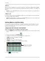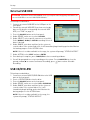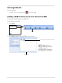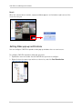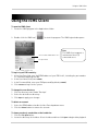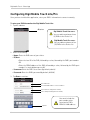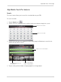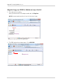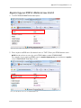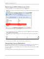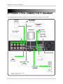
1
Thank you for purchasing this product. Digimerge is committed to providing our customers with a high quality, reliable security solution. This manual refers to the following models: • DH200+ Series For more information on this product, firmware updates, and accessory products, please visit us at: www.digimerge.com CAUTION RISK OF ELECTRIC SHOCK DO NOT OPEN CAUTION: TO REDUCE THE RISK OF ELECTRIC SHOCK DO NOT REMOVE COVER. NO USER SERVICABLE PARTS INSIDE. REFER SERVICING TO QUALIFIED SERVICE PERSONNEL. The lightning flash with arrowhead symbol, within an equilateral triangle, is intended to alert the user to the presence of uninsulated "dangerous voltage" within the products ' enclosure that may be of sufficient magnitude to constitute a risk of electric shock. The exclamation point within an equilateral triangle is intended to alert the user to the presence of important operating and maintenance (servicing) instructions in the literature accompanying the appliance. WARNING: TO PREVENT FIRE OR SHOCK HAZARD, DO NOT EXPOSE THIS UNIT TO RAIN OR MOISTURE. CAUTION: TO PREVENT ELECTRIC SHOCK, MATCH WIDE BLADE OF THE PLUG TO THE WIDE SLOT AND FULLY INSERT. Important Safeguards In addition to the careful attention devoted to quality standards in the manufacturing process of your video product, safety is a major factor in the design of every instrument. However, safety is your responsibility too. This sheet lists important information that will help to assure your enjoyment and proper use of the video product and accessory equipment. Please read them carefully before operating and using your video product. Installation 1. 2. 3. 4. 5. 6. 7. Read and Follow Instructions - All the safety and operating instructions should be read before the video product is operated. Follow all operating instructions. Retain Instructions - The safety and operating instructions should be retained for future reference. Heed Warnings - Comply with all warnings on the video product and in the operating instructions. Polarization - Do not defeat the safety purpose of the polarized or grounding-type plug. A polarized plug has two blades with one wider than the other. A grounding type plug has two blades and a third grounding prong. The wide blade or the third prong are provided for your safety. If the provided plug does not fit into your outlet, consult an electrician for replacement of the obsolete outlet. Power Sources - This video product should be operated only from the type of power source indicated on the marking label. If you are not sure of the type of power supply to your location, consult your video dealer or local power company. For video products intended to operate from battery power, or other sources, refer to the operating instructions. Overloading - Do not overload wall outlets of extension cords as this can result in the risk of fire or electric shock. Overloaded AC outlets, extension cords, frayed power cords, damaged or cracked wire insulation, and broken plugs are dangerous. They may result in a shock or fire hazard. Periodically examine the cord, and if its appearance indicates damage or deteriorated insulation, have it replaced by your service technician. Power Cord Protection - Power supply cords should be routed so that they are not likely to be walked on or pinched by items placed upon or against them, paying particular attention to cords at plugs, convenience receptacles, and the point where they exit from the video product. 8. Ventilation - Slots and openings in the case are provided for ventilation to ensure reliable operation of the video product and to protect it from overheating. These openings must not be blocked or covered. The openings should never be blocked by placing the video equipment on a bed, sofa, rug, or other similar surface. This video product should never be placed near or over a radiator or heat register. This video product should not be placed in a built-in installation such as a bookcase or rack unless proper ventilation is provided or the video product manufacturer’s instructions have been followed. 9. Attachments - Do not use attachments unless recommended by the video product manufacturer as they may cause a hazard. 10. Camera Extension Cables – Check the rating of your extension cable(s) to verify compliance with your local authority regulations prior to installation. 11. Water and Moisture - Do not use this video product near water. For example, near a bath tub, wash bowl, kitchen sink or laundry tub, in a wet basement, near a swimming pool and the like. Caution: Maintain electrical safety. Powerline operated equipment or accessories connected to this unit should bear the UL listing mark of CSA certification mark on the accessory itself and should not be modified so as to defeat the safety features. This will help avoid any potential hazard from electrical shock or fire. If in doubt, contact qualified service personnel. 12. Accessories - Do not place this video equipment on an unstable cart, stand, tripod, or table. The video equipment may fall, causing serious damage to the video product. Use this video product only with a cart, stand, tripod, bracket, or table recommended by the manufacturer or sold with the video product. Any mounting of the product should follow the manufacturer’s instructions and use a mounting accessory recommended by the manufacturer. iii Service Use 13. Servicing - Do not attempt to service this video equipment yourself as opening or removing covers may expose you to dangerous voltage or other hazards. Refer all servicing to qualified service personnel. 14. Conditions Requiring Service - Unplug this video product from the wall outlet and refer servicing to qualified service personnel under the following conditions: • When the power supply cord or plug is damaged. 19. Cleaning - Unplug the video product from the wall outlet before cleaning. Do not use liquid cleaners or aerosol cleaners. Use a damp cloth for cleaning. 20. Product and Cart Combination - Video and cart combination should be moved with care. Quick stops, excessive force, and uneven surfaces may cause the video product and car combination to overturn. 21. Object and Liquid Entry - Never push objects for any kind into this video product through openings as they may touch dangerous voltage points or “short-out” parts that could result in a fire or electric shock. Never spill liquid of any kind on the video product. 22. Lightning - For added protection for this video product during a lightning storm, or when it is left unattended and unused for long periods of time, unplug it from the wall outlet and disconnect the antenna or cable system. This will prevent damage to the video product due to lightning and power line surges. • If liquid has been spilled or objects have fallen into the video product. • If the video product has been exposed to rain or water. • If the video product does not operate normally by following the operating instructions. Adjust only those controls that are covered by the operating instructions. Improper adjustment of other controls may result in damage and will often require extensive work by a qualified technician to restore the video product to its normal operation. • If the video product has been dropped or the cabinet has been damaged. • When the video product exhibits a distinct change in performance. This indicates a need for service. 15. Replacement Parts - When replacement parts are required, have the service technician verify that the replacements used have the same safety characteristics as the original parts. Use of replacements specified by the video product manufacturer can prevent fire, electric shock or other hazards. 16. Safety Check - Upon completion of any service or repairs to this video product, ask the service technician to perform safety checks recommended by the manufacturer to determine that the video product is in safe operating condition. 17. Wall or Ceiling Mounting - The cameras provided with this system should be mounted to a wall or ceiling only as instructed in this guide, using the provided mounting brackets. 18. Heat - The product should be situated away from heat sources such as radiators, heat registers, stoves, or other products (including amplifiers) that produce heat. General Precautions iv General Precautions 1. All warnings and instructions in this manual should be followed. 2. Remove the plug from the outlet before cleaning. Do not use liquid aerosol detergents. Use a water dampened cloth for cleaning. 3. Do not use this unit in humid or wet places. 4. Keep enough space around the unit for ventilation. Slots and openings in the storage cabinet should not be blocked. 5. During lightning storms, or when the unit is not used for a long time, disconnect the power supply, antenna, and cables to protect the unit from electrical surge. FCC CLASS A NOTICE NOTE This equipment has been tested and found to comply with the limits for a Class A digital device pursuant to Part 15 of the FCC Rules. These limits are designed to provide reasonable protection against harmful interference when the equipment is operated in a commercial environment. This equipment generates, uses, and can radiate radio frequency energy and, if not installed and used in accordance with the manufacturer’s instruction manual, may cause harmful interference with radio communications. Operation of this equipment in a residential area is likely to cause harmful interference, in which case you will be required to correct the interference at your own expense. This equipment has been certified and found to comply with the limits regulated by FCC, EMC, and LVD. Therefore, it is designated to provide reasonable protection against interference and will not cause interference with other appliance usage. However, it is imperative that the user follows the guidelines in this manual to avoid improper usage which may result in damage to the unit, electrical shock and fire hazard injury. In order to improve the feature functions and quality of this product, the specifications are subject to change without notice from time to time. www.digimerge.com v Features • H.264 compression, supports D1 resolution video recording • Security Certified Hard Disk with up to 2TB of data storage • Backup through USB port to flash and optical drives* • Excellent quality live and recorded video and audio • 480fps ‘real-time’ viewing, 240fps recording (8/16 channel) • CMS-DH application supports up to 300 DVRs, 64 channels, live-playback, E-map, full • control, up to 8 screen display • 3G Smart phone viewing and control with Windows Mobile™* • Fully compatible with both PC and Mac • Lite Touch pad control *Please visit www.digimerge.com/Touch for information, firmware, and compatibility updates for mobile viewing vi TABLE OF CONTENTS Getting Started . . . . . . . . . . . . . . . . . . . . . . . . . . . . . . . . . . . . . . . . . . . . . . . . . Basic Setup . . . . . . . . . . . . . . . . . . . . . . . . . . . . . . . . . . . . . . . . . . . . . . . . . . . . Front Panel . . . . . . . . . . . . . . . . . . . . . . . . . . . . . . . . . . . . . . . . . . . . . . . . . . . . Rear Panel . . . . . . . . . . . . . . . . . . . . . . . . . . . . . . . . . . . . . . . . . . . . . . . . . . . . . Remote Control. . . . . . . . . . . . . . . . . . . . . . . . . . . . . . . . . . . . . . . . . . . . . . . . . Mouse Control . . . . . . . . . . . . . . . . . . . . . . . . . . . . . . . . . . . . . . . . . . . . . . . . . . 1 2 3 5 6 7 Mouse Tips . . . . . . . . . . . . . . . . . . . . . . . . . . . . . . . . . . . . . . . . . . . . . . . . . . . . . . . . . . . . . 7 Touch Panel Tips and Tricks . . . . . . . . . . . . . . . . . . . . . . . . . . . . . . . . . . . . . . . . . . . . . . . 7 Using the System . . . . . . . . . . . . . . . . . . . . . . . . . . . . . . . . . . . . . . . . . . . . . . . 8 Quick Setup . . . . . . . . . . . . . . . . . . . . . . . . . . . . . . . . . . . . . . . . . . . . . . . . . . . . . . . . . . . . . 8 Using Quick Setup . . . . . . . . . . . . . . . . . . . . . . . . . . . . . . . . . . . . . . . . . . . . . . . . . . . . . . . . . . . . . . . . . . . . . 8 Enabling/Disabling Quick Setup . . . . . . . . . . . . . . . . . . . . . . . . . . . . . . . . . . . . . . . . . . . . . . . . . . . . . . . . . 9 Password . . . . . . . . . . . . . . . . . . . . . . . . . . . . . . . . . . . . . . . . . . . . . . . . . . . . . . . . . . . . . . . 9 On-Screen Display . . . . . . . . . . . . . . . . . . . . . . . . . . . . . . . . . . . . . . . . . . . . . . . . . . . . . . 10 Using the Virtual Remote . . . . . . . . . . . . . . . . . . . . . . . . . . . . . . . . . . . . . . . . . . . . . . . . 11 Playback . . . . . . . . . . . . . . . . . . . . . . . . . . . . . . . . . . . . . . . . . . . . . . . . . . . . . . . . . . . . . . . . . . . . . . . . . . . . 12 Using the Virtual Keyboard . . . . . . . . . . . . . . . . . . . . . . . . . . . . . . . . . . . . . . . . . . . . . . . 12 Setting the Time . . . . . . . . . . . . . . . . . . . . . . . . . . . . . . . . . . . . . . . . . . . . . . . . . . . . . . . . 13 Multi-Screen Display . . . . . . . . . . . . . . . . . . . . . . . . . . . . . . . . . . . . . . . . . . . . . . . . . . . . 14 Repositioning Channels . . . . . . . . . . . . . . . . . . . . . . . . . . . . . . . . . . . . . . . . . . . . . . . . . . . . . . . . . . . . . . . 14 Zoom . . . . . . . . . . . . . . . . . . . . . . . . . . . . . . . . . . . . . . . . . . . . . . . . . . . . . . . . . . . . . . . . . 15 Sequential Setup (Auto Sequence) . . . . . . . . . . . . . . . . . . . . . . . . . . . . . . . . . . . . . . . . . 15 Recording. . . . . . . . . . . . . . . . . . . . . . . . . . . . . . . . . . . . . . . . . . . . . . . . . . . . . 16 Continuous Recording . . . . . . . . . . . . . . . . . . . . . . . . . . . . . . . . . . . . . . . . . . . . . . . . . . . 16 Event Recording . . . . . . . . . . . . . . . . . . . . . . . . . . . . . . . . . . . . . . . . . . . . . . . . . . . . . . . . 16 Motion . . . . . . . . . . . . . . . . . . . . . . . . . . . . . . . . . . . . . . . . . . . . . . . . . . . . . . . . . . . . . . . . . . . . . . . . . . . . . 17 Alarm . . . . . . . . . . . . . . . . . . . . . . . . . . . . . . . . . . . . . . . . . . . . . . . . . . . . . . . . . . . . . . . . . . . . . . . . . . . . . . 18 Video Loss . . . . . . . . . . . . . . . . . . . . . . . . . . . . . . . . . . . . . . . . . . . . . . . . . . . . . . . . . . . . . . . . . . . . . . . . . . 18 Setting Motion-only Recording . . . . . . . . . . . . . . . . . . . . . . . . . . . . . . . . . . . . . . . . . . . . 18 Enabling Motion-only recording . . . . . . . . . . . . . . . . . . . . . . . . . . . . . . . . . . . . . . . . . . . . . . . . . . . . . . . . 18 Setting Continuous & Motion Recording (C+M) . . . . . . . . . . . . . . . . . . . . . . . . . . . . . . . 20 Schedule Recording . . . . . . . . . . . . . . . . . . . . . . . . . . . . . . . . . . . . . . . . . . . . . . . . . . . . . 22 Recording Audio . . . . . . . . . . . . . . . . . . . . . . . . . . . . . . . . . . . . . . . . . . . . . . . . . . . . . . . . 22 Playback. . . . . . . . . . . . . . . . . . . . . . . . . . . . . . . . . . . . . . . . . . . . . . . . . . . . . . 23 Search . . . . . . . . . . . . . . . . . . . . . . . . . . . . . . . . . . . . . . . . . . . . . . . . . . . . . . . 24 Using the Main Menu . . . . . . . . . . . . . . . . . . . . . . . . . . . . . . . . . . . . . . . . . . . 25 DISPLAY . . . . . . . . . . . . . . . . . . . . . . . . . . . . . . . . . . . . . . . . . . . . . . . . . . . . . . . . . . . . . . . 26 vii Sequential Setup . . . . . . . . . . . . . . . . . . . . . . . . . . . . . . . . . . . . . . . . . . . . . . . . . . . . . . . . . . . . . . . . . . . . . 26 Auto Sequence with Front Panel and Remote Control . . . . . . . . . . . . . . . . . . . . . . . . . . . . . . . . . . . . . . . . . . . . . . 26 CAMERA . . . . . . . . . . . . . . . . . . . . . . . . . . . . . . . . . . . . . . . . . . . . . . . . . . . . . . . . . . . . . . . 27 CONFIGURING MOTION . . . . . . . . . . . . . . . . . . . . . . . . . . . . . . . . . . . . . . . . . . . . . . . . . . 27 RECORD . . . . . . . . . . . . . . . . . . . . . . . . . . . . . . . . . . . . . . . . . . . . . . . . . . . . . . . . . . . . . . . 28 SCHEDULE . . . . . . . . . . . . . . . . . . . . . . . . . . . . . . . . . . . . . . . . . . . . . . . . . . . . . . . . . . . . 28 Stopping Scheduled Recording . . . . . . . . . . . . . . . . . . . . . . . . . . . . . . . . . . . . . . . . . . . . . . . . . . . . . . . . . 29 Overnight Recording . . . . . . . . . . . . . . . . . . . . . . . . . . . . . . . . . . . . . . . . . . . . . . . . . . . . . . . . . . . . . . . . . . 29 Example . . . . . . . . . . . . . . . . . . . . . . . . . . . . . . . . . . . . . . . . . . . . . . . . . . . . . . . . . . . . . . . . . . . . . . . . . . . . . . . . . . . . 29 EVENT . . . . . . . . . . . . . . . . . . . . . . . . . . . . . . . . . . . . . . . . . . . . . . . . . . . . . . . . . . . . . . . . 30 DEVICE . . . . . . . . . . . . . . . . . . . . . . . . . . . . . . . . . . . . . . . . . . . . . . . . . . . . . . . . . . . . . . . . 30 NETWORK . . . . . . . . . . . . . . . . . . . . . . . . . . . . . . . . . . . . . . . . . . . . . . . . . . . . . . . . . . . . . 32 EMAIL . . . . . . . . . . . . . . . . . . . . . . . . . . . . . . . . . . . . . . . . . . . . . . . . . . . . . . . . . . . . . . . . . . . . . . . . . . . . . . 32 DDNS . . . . . . . . . . . . . . . . . . . . . . . . . . . . . . . . . . . . . . . . . . . . . . . . . . . . . . . . . . . . . . . . . . . . . . . . . . . . . . 33 MISC . . . . . . . . . . . . . . . . . . . . . . . . . . . . . . . . . . . . . . . . . . . . . . . . . . . . . . . . . . . . . . . . . . . . . . . . . . . . . . . 33 SYSTEM . . . . . . . . . . . . . . . . . . . . . . . . . . . . . . . . . . . . . . . . . . . . . . . . . . . . . . . . . . . . . . . 34 GENERAL . . . . . . . . . . . . . . . . . . . . . . . . . . . . . . . . . . . . . . . . . . . . . . . . . . . . . . . . . . . . . . . . . . . . . . . . . . . 34 TIME . . . . . . . . . . . . . . . . . . . . . . . . . . . . . . . . . . . . . . . . . . . . . . . . . . . . . . . . . . . . . . . . . . . . . . . . . . . . . . . 34 ACCOUNT . . . . . . . . . . . . . . . . . . . . . . . . . . . . . . . . . . . . . . . . . . . . . . . . . . . . . . . . . . . . . . . . . . . . . . . . . . . 34 DISK . . . . . . . . . . . . . . . . . . . . . . . . . . . . . . . . . . . . . . . . . . . . . . . . . . . . . . . . . . . . . . . . . . . . . . . . . . . . . . . 35 Formatting Disks . . . . . . . . . . . . . . . . . . . . . . . . . . . . . . . . . . . . . . . . . . . . . . . . . . . . . . . . . . . . . . . . . . . . . . . . . . . . 35 Disk Monitor . . . . . . . . . . . . . . . . . . . . . . . . . . . . . . . . . . . . . . . . . . . . . . . . . . . . . . . . . . . . . . . . . . . . . . . . . . . . . . . . 35 . . . . . . . . . . . . . . . . . . . . . . . . . . . . . . . . . . . . . . . . . . . . . . . . . . . . . . . . . . . . . . . . . . . . . . . . . . . . . . . . . . . . . . . . . . . 35 Auto Delete . . . . . . . . . . . . . . . . . . . . . . . . . . . . . . . . . . . . . . . . . . . . . . . . . . . . . . . . . . . . . . . . . . . . . . . . . . . . . . . . . 35 UPDATE . . . . . . . . . . . . . . . . . . . . . . . . . . . . . . . . . . . . . . . . . . . . . . . . . . . . . . . . . . . . . . . . . . . . . . . . . . . . 36 INFO . . . . . . . . . . . . . . . . . . . . . . . . . . . . . . . . . . . . . . . . . . . . . . . . . . . . . . . . . . . . . . . . . . . . . . . . . . . . . . . 36 Backup . . . . . . . . . . . . . . . . . . . . . . . . . . . . . . . . . . . . . . . . . . . . . . . . . . . . . . . 37 USB Flash Drive . . . . . . . . . . . . . . . . . . . . . . . . . . . . . . . . . . . . . . . . . . . . . . . . . . . . . . . . 37 External USB HDD . . . . . . . . . . . . . . . . . . . . . . . . . . . . . . . . . . . . . . . . . . . . . . . . . . . . . . 38 USB CD/DVD-RW . . . . . . . . . . . . . . . . . . . . . . . . . . . . . . . . . . . . . . . . . . . . . . . . . . . . . . . 38 Time Search and Backup . . . . . . . . . . . . . . . . . . . . . . . . . . . . . . . . . . . . . . . . . . . . . . . . . 39 Viewing Backup Video . . . . . . . . . . . . . . . . . . . . . . . . . . . . . . . . . . . . . . . . . . . . . . . . . . . 40 Using MCD Player . . . . . . . . . . . . . . . . . . . . . . . . . . . . . . . . . . . . . . . . . . . . . . . . . . . . . . . 41 CMS-DH Central Management Software . . . . . . . . . . . . . . . . . . . . . . . . . . . 43 System Requirements . . . . . . . . . . . . . . . . . . . . . . . . . . . . . . . . . . . . . . . . . . . . . . . . . . . 43 Prerequisites . . . . . . . . . . . . . . . . . . . . . . . . . . . . . . . . . . . . . . . . . . . . . . . . . . . . . . . . . . 43 Installing CMS-DH . . . . . . . . . . . . . . . . . . . . . . . . . . . . . . . . . . . . . . . . . . . . . . . . . . . . . . 44 Starting CMS-DH . . . . . . . . . . . . . . . . . . . . . . . . . . . . . . . . . . . . . . . . . . . . . . . . . . . . . . . 45 Adding a Virtual DVR . . . . . . . . . . . . . . . . . . . . . . . . . . . . . . . . . . . . . . . . . . . . . . . . . . . . 50 Creating New Group Folders & Sub folders . . . . . . . . . . . . . . . . . . . . . . . . . . . . . . . . . 52 Configuring General System Settings . . . . . . . . . . . . . . . . . . . . . . . . . . . . . . . . . . . . . . 53 Adding Users . . . . . . . . . . . . . . . . . . . . . . . . . . . . . . . . . . . . . . . . . . . . . . . . . . . . . . . . . . . 54 Recording Video to the hard drive . . . . . . . . . . . . . . . . . . . . . . . . . . . . . . . . . . . . . . . . . 55 Playing back recorded video . . . . . . . . . . . . . . . . . . . . . . . . . . . . . . . . . . . . . . . . . . . . . . 56 Remote Search . . . . . . . . . . . . . . . . . . . . . . . . . . . . . . . . . . . . . . . . . . . . . . . . . . . . . . . . . 57 viii Video Playback Controls . . . . . . . . . . . . . . . . . . . . . . . . . . . . . . . . . . . . . . . . . . . . . . . . . . . . . . . . . . . . . . . 58 Local Search . . . . . . . . . . . . . . . . . . . . . . . . . . . . . . . . . . . . . . . . . . . . . . . . . . . . . . . . . . . 58 Saving Video Files . . . . . . . . . . . . . . . . . . . . . . . . . . . . . . . . . . . . . . . . . . . . . . . . . . . . . . . . . . . . . . . . . . . . 59 Converting video files to AVI . . . . . . . . . . . . . . . . . . . . . . . . . . . . . . . . . . . . . . . . . . . . . . . . . . . . . . . . . . . . 60 Schedule Recording . . . . . . . . . . . . . . . . . . . . . . . . . . . . . . . . . . . . . . . . . . . . . . . . . . . . . 61 Schedule Backup . . . . . . . . . . . . . . . . . . . . . . . . . . . . . . . . . . . . . . . . . . . . . . . . . . . . . . . 61 Taking Screen Captures . . . . . . . . . . . . . . . . . . . . . . . . . . . . . . . . . . . . . . . . . . . . . . . . . 63 Viewing File Download Status . . . . . . . . . . . . . . . . . . . . . . . . . . . . . . . . . . . . . . . . . . . . . 63 Changing viewing modes . . . . . . . . . . . . . . . . . . . . . . . . . . . . . . . . . . . . . . . . . . . . . . . . . 64 E-Map Setup . . . . . . . . . . . . . . . . . . . . . . . . . . . . . . . . . . . . . . . . . . . . . . . . . . . . . . . . . . . . . . . . . . . . . . . . 66 Viewing video on E-Map . . . . . . . . . . . . . . . . . . . . . . . . . . . . . . . . . . . . . . . . . . . . . . . . . . . . . . . . . . . . . . . 67 Configuring E-Map camera settings . . . . . . . . . . . . . . . . . . . . . . . . . . . . . . . . . . . . . . . . . . . . . . . . . . . . . 67 Zooming into the E-Map . . . . . . . . . . . . . . . . . . . . . . . . . . . . . . . . . . . . . . . . . . . . . . . . . . . . . . . . . . . . . . . 68 Removing camera icon in the E-Map . . . . . . . . . . . . . . . . . . . . . . . . . . . . . . . . . . . . . . . . . . . . . . . . . . . . 68 Adding Multiple E-Maps . . . . . . . . . . . . . . . . . . . . . . . . . . . . . . . . . . . . . . . . . . . . . . . . . 68 Viewing DVR Health . . . . . . . . . . . . . . . . . . . . . . . . . . . . . . . . . . . . . . . . . . . . . . . . . . . . . 69 Closing windows . . . . . . . . . . . . . . . . . . . . . . . . . . . . . . . . . . . . . . . . . . . . . . . . . . . . . . . . 69 Locking Windows . . . . . . . . . . . . . . . . . . . . . . . . . . . . . . . . . . . . . . . . . . . . . . . . . . . . . . . 69 DVR Log . . . . . . . . . . . . . . . . . . . . . . . . . . . . . . . . . . . . . . . . . . . . . . . . . . . . . . . . . . . . . . . 70 Setting PTZ Pre-Sets . . . . . . . . . . . . . . . . . . . . . . . . . . . . . . . . . . . . . . . . . . . . . . . . . . . . . . . . . . . . . . . . . 72 Upgrading the firmware remotely (DH200+ Series only) . . . . . . . . . . . . . . . . . . . . . . . 74 Configuring Post Event Action Tab . . . . . . . . . . . . . . . . . . . . . . . . . . . . . . . . . . . . . . . . . 75 Setting up Post Event Actions on a NO/NC Device . . . . . . . . . . . . . . . . . . . . . . . . . . . . . . . . . . . . . . . . . . 75 Configuring Alarm Output . . . . . . . . . . . . . . . . . . . . . . . . . . . . . . . . . . . . . . . . . . . . . . . . 76 Setting message pop-up notifications . . . . . . . . . . . . . . . . . . . . . . . . . . . . . . . . . . . . . . . . . . . . . . . . . . . . 77 Setting Video pop-up notifications . . . . . . . . . . . . . . . . . . . . . . . . . . . . . . . . . . . . . . . . . . . . . . . . . . . . . . . 78 Configuring other Post Action Events . . . . . . . . . . . . . . . . . . . . . . . . . . . . . . . . . . . . . . 80 POS Data Search . . . . . . . . . . . . . . . . . . . . . . . . . . . . . . . . . . . . . . . . . . . . . . . . . . . . . . . . 80 Running CMS-DH on multiple monitors . . . . . . . . . . . . . . . . . . . . . . . . . . . . . . . . . . . . 81 iSMS Client (Remote Viewing on the Mac) . . . . . . . . . . . . . . . . . . . . . . . . . . 82 System Requirements . . . . . . . . . . . . . . . . . . . . . . . . . . . . . . . . . . . . . . . . . . . . . . . . . . . 82 Prerequisites . . . . . . . . . . . . . . . . . . . . . . . . . . . . . . . . . . . . . . . . . . . . . . . . . . . . . . . . . . 82 Installation Steps . . . . . . . . . . . . . . . . . . . . . . . . . . . . . . . . . . . . . . . . . . . . . . . . . . . . . . . 82 Using the iSMS Client . . . . . . . . . . . . . . . . . . . . . . . . . . . . . . . . . . . . . . . . . . . 83 iSMS Interface . . . . . . . . . . . . . . . . . . . . . . . . . . . . . . . . . . . . . . . . . . . . . . . . . . . . . . . . . 84 Configuring OSD Settings . . . . . . . . . . . . . . . . . . . . . . . . . . . . . . . . . . . . . . . . . . . . . . . . 86 Searching for video remotely . . . . . . . . . . . . . . . . . . . . . . . . . . . . . . . . . . . . . . . . . . . . . 86 Searching for video locally . . . . . . . . . . . . . . . . . . . . . . . . . . . . . . . . . . . . . . . . . . . . . . . 89 Configuring PTZ settings . . . . . . . . . . . . . . . . . . . . . . . . . . . . . . . . . . . . . . . . . . . . . . . . . 90 Configuring PTZ Protocols in the iSMS Client . . . . . . . . . . . . . . . . . . . . . . . . . . . . . . . . 92 Configuring the iSMS Client . . . . . . . . . . . . . . . . . . . . . . . . . . . . . . . . . . . . . 93 Digi Imobile Touch - iPhone App. . . . . . . . . . . . . . . . . . . . . . . . . . . . . . . . . . 94 Digi iMobile Touch Lite - ANDROID. . . . . . . . . . . . . . . . . . . . . . . . . . . . . . . 103 ix Installing the BDVRViewer App on your Blackberry . . . . . . . . . . . . . . . . Appendix A: System Specifications . . . . . . . . . . . . . . . . . . . . . . . . . . . . . . Appendix B: Setting up Remote Viewing . . . . . . . . . . . . . . . . . . . . . . . . . . Appendix C: Digimerge Auto Port Forwarding Wizard . . . . . . . . . . . . . . Appendix D: Setting Up DDNS Service . . . . . . . . . . . . . . . . . . . . . . . . . . . . Appendix E: Setting Up Mobile Access. . . . . . . . . . . . . . . . . . . . . . . . . . . . Appendix F: Connecting PTZ Cameras . . . . . . . . . . . . . . . . . . . . . . . . . . . . Appendix G: Connecting Additional External Monitors . . . . . . . . . . . . . . Appendix H: Connecting Motion / Alarm Devices . . . . . . . . . . . . . . . . . . . Appendix I: Full Connectivity Diagram. . . . . . . . . . . . . . . . . . . . . . . . . . . . Appendix J: Replacing the Hard Drive . . . . . . . . . . . . . . . . . . . . . . . . . . . . Appendix K: Using Listen-in Audio . . . . . . . . . . . . . . . . . . . . . . . . . . . . . . . Appendix L: Converting Video Files to AVI . . . . . . . . . . . . . . . . . . . . . . . . Appendix M: Remote Viewing using Internet Explorer . . . . . . . . . . . . . . Troubleshooting . . . . . . . . . . . . . . . . . . . . . . . . . . . . . . . . . . . . . . . . . . . . . . x 108 112 114 117 124 127 131 135 136 138 139 142 143 145 147 GETTING STARTED The system comes with the following components: DIGIMERGE TOUCH+ DIGITAL VIDEO RECORDER POWER SUPPLY OCTOPUS CABLE [16-CHANNEL ETHERNET CABLEONLY] MOUSE REMOTE CONTROL INSTRUCTION MANUAL, QUICKSTART GUIDE, & SOFTWARE CD HARD DRIVE SIZE, NUMBER OF CHANNELS, AND CAMERA CONFIGURATION MAY VARY BY MODEL. PLEASE REFER TO YOUR PACKAGE FOR SPECIFIC CONTENT DETAILS. CHECK YOUR PACKAGE TO CONFIRM THAT YOU HAVE RECEIVED THE COMPLETE SYSTEM, INCLUDING ALL COMPONENTS SHOWN ABOVE. 1 BASIC SETUP 1. Connect the cameras a. Connect BNC cameras to the BNC ports on the rear panel (4/8-channel models). OR a. 16-CHANNEL MODELS ONLY: Connect the single end of the octopus cable to the VIDEO IN1-16 port (see figure 1.1). Figure 1.0 Connect BNC cameras to the system b. Connect BNC cameras to the octopus cable. 2. Connect a monitor a. Connect a VGA cable (not included) from the VGA port on the rear panel to the VGA port on your monitor. Figure 1.1 Octopus cable port (16-channel only) OR a. Connect a BNC terminated cable from one of the Video OUT ports to a TV or CCTV monitor. 3. Connect the mouse (USB or PS/2) a. Connect the mouse to the USB mouse port on the rear panel. Figure 1.2 Connect to a VGA or CCTV monitor, or a TV NOTE: If using a PS/2 mouse, a USB adapter will be required (not included). 4. Connect the Ethernet cable a. Connect an Ethernet cable to the LAN port on the rear panel of system; connect the other end of the Ethernet cable to an empty LAN port on your router or switch (not included). Figure 1.3 Connect an Ethernet cable and mouse 5. Connect the power cable a. Connect the power supply to the DC 12V port on the rear panel of the system; connect the power cable to an outlet, power strip, or surge protector. 2 Figure 1.4 Connect the power cable FRONT PANEL 1 2 3 10 4 11 6 5 12 13 14 7 8 9 15 Figure 1.5 Front panel (8-channel model shown) 1. Channel buttons: Press to view channels individually in full-screen. 2. : Press to increase values in menu options. 3. : Press to switch between full-screen single channel, quad, and split-screen display views. 4. : Press to confirm menu options. 5. / 6. CLR: Press to perform the following: • Live viewing: Show/hide onscreen display (OSD) • Playback: Play/pause playback • Menu: Move cursor up 7. : Press to perform the following: • Live viewing: Start/Stop recording (password required for stoppage) • Playback: Increase reverse playback speed 1X, 2X, 4X, 8X, and 16X • Menu: Move cursor left /: Press to perform the following: • Live viewing: Start/stop scheduled recording (Recording Schedule must already be configured; password required for stoppage) • Playback: Increase forward playback 1X, 2X, 4X, 8X, and 16X • Menu: Move cursor right 8. LEDs: REC will be solid red during recording; HDD will flash green when the system is accessing the HDD. 9. POWER: Press to power the system ON/OFF (password required). 3 Front Panel Front Panel (cont’d.) 1 2 3 10 4 11 12 6 5 13 14 7 8 9 15 Figure 1.6 Front panel (8-channel model shown) 10. : Press to decrease values in menu options. 11. : Press to open/close the Time Search menu. 12. : Press to open/close the Backup menu. 13. MENU/ESC: Press to open/close the Main Menu; press to close menu windows. 14. /: Press to perform the following: • Live viewing: Open the Log menu • Playback: Stop playback • Menu: Move cursor down 15. USB Port: Connect a USB flash drive, HDD, or optical drive for critical data backup; connect a USB flash drive for firmware upgrades 4 REAR PANEL 1 2 3 8 9 4 5 6 7 10 11 12 Figure 1.7 Rear panel (8-channel model shown) 1. CAMERA IN: Camera input ports for BNC cameras (4/8-channel); VIDEO IN 1-16: Port for octopus cable (16-channel models only—see figure 1.8) 2. VIDEO OUT: Video output (BNC) to connect the system to a secondary monitor or DVR. 3. AUDIO IN: One 3.5" RCA port (mono) for recording audio from an audio capable camera (not included). 4. VGA: VGA port to connect the system to a VGA monitor. 5. LAN: Connect an Ethernet cable to connect the system to a router or switch (not included). 6. MOUSE: USB port to connect a USB or PS/2 mouse (PS/2 mouse requires USB adapter). NOTE: On the 4-channel DH200+ models, the rear USB port is used for the mouse only. Do not connect a USB flash drive / external DVD writer to the rear USB port. NOTE: On the 4-channel DH200+ models, you must use a PS/2 compatible USB mouse (included). A regular USB 2.0 mouse will not work on the rear panel USB port. 7. ALARM IN: Alarm block to connect external alarm or motion devices (not included). 8. SPOT OUT: Video output to connect the system to an external monitor (not included). Spot Out mode only displays channels switching in an automatic sequence. 9. AUDIO OUT: One 3.5" RCA port (mono) for audio output. 10. RS422 / 485 / OUT: Connection block for an RS422/485 PTZ camera (not included). NOTE: The RS232 ports are for development purposes only. A PTZ camera cannot be controlled from these ports. 11. DC 12V: Port for 12V DC 3A power supply (included). 12. Exhaust fan: Do not block. Keep clear to allow for proper ventilation. Figure 1.8 Octopus cable VIDEO IN (16-channel only) 5 REMOTE CONTROL 1 POWER: Press to power the system ON/OFF (password required). 2. Navigation/Menu: 1 • S: Press to move cursor up • T: Press to move cursor down 8 9 2 • W: Press to move cursor left • X: Press to move cursor right 10 • MENU: Press to open the Main Menu 3. : Press to switch between single channel full-screen, quad, and split-screen displays. 3 4 : Press to confirm menu options/selections. 4. 5. 11 Playback controls: • : Press to increase reverse playback speed 1X, 2X, 4X, 8X, and 16X. 5 • WX: Press to begin playback; press to switch between forward and reverse playback • : Press to increase forward playback speed 1X, 2X, 4X, 8X, and 16X • 6 : During playback, press to pause; press repeatedly for frame-by-frame playback; during live viewing, press to open the PTZ menu • : Press to stop playback • : During playback, press to pause; press 7 repeatedly for frame-by-frame playback; during live viewing, press to Spot Out. 6. 7. Channel buttons: Press to view channels 1~8 individually in full-screen; press to input passwords; when entering camera titles, press for alpha-numeric characters. : Press to open the Time Search menu. 8. CANCEL/ESC: Press to close menu windows; press to show/hide the on-screen display (OSD); press to clear channel indicators (loss, alarm, etc.). 9. +: Press to increase values in menu options. 10. - : Press to decrease menu options in menu options. 11. 6 z: Press to start/stop manual recording. You can use the channel buttons on the remote control to enter numbers, letters, and other characters. MOUSE CONTROL The mouse is the primary control device for the system. To connect a USB mouse: • Connect a USB / PS/2 mouse to the USB port on the rear panel—DO NOT connect the mouse to the USB port on the front panel. The USB port on the front panel is strictly intended for data transfer. 1 2 3 1. Left-Button: While in a split-screen display mode, double-click an individual channel to view it in full-screen; double-click again to return to the split-screen display mode. While navigating menus, click to select a menu option; double-click to open the next menu. 2. Right-Button: Right-click anywhere on the screen to open the Virtual Remote; double-click anywhere on the screen to return to the previous menu. Scroll-Wheel: Move the scroll wheel up or down to increase/decrease the value of a selected menu option. 3. Mouse Tips When using the mouse, the ENTER and EXIT buttons appear in the top-right corner of every menu window. When you change system settings and configurations, click to confirm your changes. Touch Panel Tips and Tricks If using the Touch panel, you will often use the following buttons when controlling the system: • CLR: Menus: move cursor up; Playback: pause playback; Live viewing: show/hide OSD; clear channel icons • /: Menus: move cursor down; Playback: stop playback; Live viewing: open Log menu • / : Menus: move cursor left; Playback: increase reverse playback speed; Live viewing: start/stop recording • /: Menus: move cursor right; Playback: increase forward playback speed; Live viewing: start/stop scheduled recording • Press the MENU/ESC button to open the main menu AND close windows/exit NOTE: This manual refers to the CANCEL/ESC button on the remote control for closing/exiting menu windows. If using the front panel, press MENU/ESC to close/exit menu windows. • Press the button to increase values for selected menu options • Press the button to decrease values for selected menu options • Press the button to enter/confirm. 7 USING THE SYSTEM The default system password is 000000 To power the system ON/OFF: 1. Connect the power cable to the port on the rear panel. 2. Press the POWER button on the front panel or remote control. NOTE: You need to press the Power button for initial startup only. The system will load the live viewing screen on subsequent resets. NOTE: You will need to input your system password to power off the system. Quick Setup By default, the system has Quick Setup disabled. Quick Setup lets you quickly adjust the time and record mode on the system. The system menu will appear as the Quick Setup menu with only Time and Record options available. To access the Quick Setup menu, from the Main menu, select Display>Quick Setup. Then select "ON" to enable Quick Setup. Figure 2.0 Quick Setup menu Using Quick Setup Use Quick Setup to set the time and configure basic recording settings. To set the time: 1. Under the Time tab, select DATE and press the ENTER button. Enter the month, day, and year. 2. Select TIME and enter the time (hh/mm/ss). NOTE: If using the mouse, you will enter the date and time with the Virtual Keyboard. 3. Press the ENTER button to save your changes. To configure recording settings: 1. Stop ALL RECORDING on the system. Enter your system password (by default, 000000). 2. Under the RECORD tab, select RECORD MODE and select one of the following: CIF 4CH, FIELD 4CH, FRAME 4CH, CIF 8CH, FIELD 8CH, FRAME 8CH, or CIF + FRAME. NOTE: If "CIF + FRAME" recording mode is selected, only channel 1 will record in frame—the remaining channels will record in CIF. 3. Under the RECORD tab, select RECORDING DAYS. Press the +/ - buttons and select 12 HOURS, 1~6 DAYS, 1~20 WEEKS, or NONE. 8 Using the System Using Quick Setup (cont’d.) 4. Under PRIORITY, select QUALITY (the quality of the video) or RATE (frames per second). If you select RATE, the video quality and frames per second will be at the lowest possible setting. This will reduce overall video quality, but will maximize the available hard drive space. Adjust this setting to best suit your recording environment and security needs. For details on configuring recording options, see “RECORD” on page 28. NOTE: The necessary recording parameters will appear under RECORD SETUP INFO at the bottom of the Quick Setup window. 5. Press the ENTER button to save your settings. Enabling/Disabling Quick Setup You must disable Quick Setup in order to access the full system main menu. To disable Quick Setup: 1. Under the ADVANCED tab, select RUN ADVANCED. 2. Select ON and press the ENTER button. The window closes. Quick Setup has been disabled. The full main menu will appear when you press the MENU button. To enable Quick Setup: 1. Press the MENU button. The Main menu opens. 2. Select DISPLAY and press the ENTER button. 3. Under the DISPLAY SETUP tab, move the cursor to QUICK SETUP, select ON and press the ENTER button. 4. Press the CANCEL/ESC button to exit. Press the MENU button again to open the Quick Setup menu. Password The default system password is 000000. However, you do not have to enter a password upon initial startup. You can enable this option in Main Menu>System>General. For details, see “GENERAL” on page 34. For complete information on changing your password and managing users on the system, see “ACCOUNT” on page 34. Figure 3.0 Enable password (optional) 9 Using the System On-Screen Display The system shows the following for all display views: 1 2 3 6 4 7 5 8 Figure 4.0 Main system display 1. Recording: "REC" indicates that continuous recording is enabled on at least one channel. NOTE: If REC does not appear on the onscreen display the system is NOT RECORDING. 2. Display: Show live video and playback in single channel full-screen, quad, and split-screen configurations. 3. Camera Status: Will display a green Motion icon, purple Loss icon, or red Alarm icon. 4. Channel number: By default, the individual channel number appears at the bottom of the frame with either a RED number (recording) or WHITE number (no recording). NOTE: A white number may mean that a channel has been assigned motion recording. For details, see “Recording” on page 16. 5. Status: Shows recording, display type, and network status. "R" indicates recording; indicates schedule recording. NOTE: Always check for these icons. If "R" does not appear in the status bar, the system is NOT RECORDING. If does not appear in the status bar, Schedule Recording is NOT ENABLED. 6. Channel Title: You can customize the channel with a unique name for each channel. See “CAMERA” on page 27. 7. Date/Time: Shows the date (mm/dd/yyyy), day of the week, and time (24-hour clock). 8. HDD/Record days: The percentage of free space remaining on the hard disk; number of recording days remaining. 10 Using the System Using the Virtual Remote Right-click anywhere on the screen to open the Virtual Remote. The Virtual Remote gives you quick access to many of the system’s features using only a USB mouse (included). 1 1. Quick Function Keys: • • : Time Search :Window Positioning • Log • Spot Out 2. • • System Info Backup • : Display Mode • Zoom • PTZ Navigation/Menu: 2 • S: Move cursor up • T: Move cursor down • W: Move cursor left • X: Move cursor right • MENU: Press to open/close the Main Menu; press to close menu windows • : ENTER/confirm menu options/selections 3 • ESC: Close menu windows; press to show/hide the onscreen display (OSD); press to clear channel indicators (loss, alarm, etc.) • +: Increase values in menu options. • - : Decrease menu options in menu options 3. Playback controls: • : Stop playback 4 • : Increase reverse playback speed 1X, 2X, 4X, 8X, and 16X • X: Start playback; press to switch between forward and reverse playback Figure 4.1 Virtual Remote • : Increase forward playback speed 1X, 2X, 4X, 8X, and 16X • z: Start manual recording (if scheduled recording is not active) • 4. : Starts/stops Schedule Recording • : During playback, click to pause; click repeatedly for frame-by-frame playback; during live viewing, click to open the PTZ menu • : During playback, click to pause; click repeatedly for frame-by-frame playback; during live viewing, click to SPOT OUT Channel buttons: Click to view channels 1~8 individually in full-screen; click to input passwords; when entering camera titles, click for alpha-numeric characters. NOTE: The button labeled 0/10 means 0 when entering passwords, and 10 when entering channel 10 for the 16 channel model DVR. 11 Using the System Playback During playback, you can right-click anywhere on the screen to open a condensed version of the Virtual Remote. 1 1. Navigation/Menu: • S: Move cursor up • T: Move cursor down • W: Move cursor left • X: Move cursor right • ZOOM: Click to open/close the Zoom windows. Click zoom then click + / - to increase 2X, 4X. • to activate 2 : Click to confirm menu options/selections 3 • ESC: Click to close menu windows; click to show/hide the onscreen display (OSD); click to clear channel indicators (loss, alarm, etc.) • +: Increase values in menu options. Figure 4.2 Virtual Remote during Playback • - : Decrease menu options in menu options 2. Playback controls: • : Stop playback • : Increase reverse playback speed 1X, 2X, 4X, 8X, and 16X • X: Start playback; press to switch between forward and reverse playback • : Increase forward playback speed 1X, 2X, 4X, 8X, and 16X 3. Quick Function Keys: • : Click to open the Time Search menu • Log: Click to open the Log menu • : During playback, click to pause; click repeatedly for frame-by-frame playback • : During playback, click to pause; click repeatedly for frame-by-frame playback Using the Virtual Keyboard When configuring certain options, such as Camera Title, the Virtual Keyboard opens to make mouse input easier. Figure 4.3 Virtual Keyboard 12 Using the System Setting the Time It is highly recommended to set the time on the system prior to doing any recording. NOTE: All recording must be stopped on the system in order to set the time. Figure 5.0 Time menu To set the date and time: button 1. Stop recording on the system by pressing / on the front panel, or pressing the on the remote control and enter your 6-digit system password (by default, 000000). NOTE: If using the mouse, right-click and then click on the Virtual Remote. 2. Press the MENU button to open the system menu. Select SYSTEM and press the ENTER button. The System menu opens. 3. Select the TIME tab. 4. Select DATE and enter the date (mm/dd/yyyy). 5. Select TIME and enter the time (hh/mm/ss). NOTE: If using the mouse, use the Virtual Keyboard to enter the date and time. 6. Press the ENTER button to save your changes. 7. Press / on the front panel, or press the button on the remote control to resume Continuous Recording. NOTE: If using the mouse, right-click and then click on the Virtual Remote. 13 Using the System Multi-Screen Display The system can display channels in full-screen single channel, quad, and multi split-screen displays. Full-Screen Quad Split-Screen 1 Split-Screen 2 (16-channel models only) Repositioning Channels You can reposition the channels on the display screen. This can be very useful when monitoring a live location(s). To reposition the display channels: 1. Using the mouse, remote control, or front panel, place the main display screen in either a quad display, or in a multi split-screen configuration. NOTE: Repositioning will not work if the main display screen is in full-screen single channel. 1. Using the mouse, right-click anywhere on the screen to open the Virtual Remote. 2. From the Virtual Remote, click . The Blue Window cursor appears in the top-left channel (typically channel 1). 3. Reposition the channels through the following: • Remote Control: Press the button for the channel you wish to place in the location of the Blue Window cursor. For example, if the cursor is on channel 1, and you want to have channel 4 in its location, press the 4 button on the remote control • Front Panel: Press the button for the channel you wish to place in the location of the Blue Window cursor Figure 6.0 Blue Window cursor is in channel 1 Press the 3 button to move channel 3 to the channel 1 position. Figure 6.1 Channels repositioned Channel 3 is now in the channel 1 position. 4. Press the STWX to change the location of the Blue Window cursor. 5. Press the ENTER button to save your settings. 14 Using the System Zoom Use the system’s built-in 2X digital zoom to get a closer look at images in full-screen (full-screen mode only). To use zoom: 1. From live viewing, press the number buttons on the front panel or remote control to select a channel to view in full-screen. NOTE: The zoom function will not work if the main display screen is in quad or split-screen configurations. 2. Press the ENTER button. The OSD disappears. A black frame appears in the center of the screen. OPTIONAL: Once the frame is visible, you can also perform the following: • Press + / - to shrink the frame • Press the ENTER button to zoom in 2X Figure 7.0 Zoom frame (full-screen only) 3. Once the frame is visible, perform any of the following: • Press STWX to move the frame anywhere on the screen • Press the ENTER button to zoom in 1X • Press + to zoom in 2X; press - to zoom out 1X • Press STWX to scan the image 4. Press the CANCEL/ESC button to exit zoom and return to live viewing. Sequential Setup (Auto Sequence) Sequential Setup (Auto Sequence) allows you to view connected cameras in an automatic sequence. Sequential Setup can include both full-screen and split screen modes. For more details on Sequential Setup, see see “Sequential Setup” on page 26. 15 RECORDING By default, the system is set to immediately record at startup from connected cameras— continuous recording. It is highly recommended to keep continuous recording on at all times. The system can perform Continuous Recording, Event Recording, and Schedule Recording. However, the system can only perform one type of recording at a given time. Continuous Recording By default, all camera channels are enabled with continuous recording. During Continuous Recording, the REC icon appears in the top left corner of the OSD, "R" appears in the status bar at the bottom of the OSD, and any connected cameras will have their channel numbers in RED (see figure 0.0). 1 2 3 4 • In this example, Continuous Recording is on ALL channels (default) Figure 8.0 Continuous recording on all channels (4CH model shown) Event Recording The system includes three modes of event recording: • Motion: The system only records when motion is detected by the affected camera • Alarm: The system records when an alarm or sensor is triggered • Video Loss: The system records when a camera is disconnected or suffers video loss. The system employs a pre-record function to capture video seconds before the video loss occurred You can customize the recording parameters (video quality, frames-per-second) of Event Recording in the Record menu. See “RECORD” on page 28. 16 Recording Motion Motion Detection must be applied to specific cameras. If you assign Motion Detection to a camera, that camera will only record when a motion event is triggered. The camera enabled with Motion Detection will have a WHITE number on the OSD (see figure 8.1). 1 2 3 4 • In this example, motion detection was assigned to camera 4, so the channel number is WHITE • Continuous Recording remains on channels 1~3 Figure 8.1 Motion assigned to channel 4 (4CH model shown) NOTE: A white number can also indicate that recording on a camera has been disabled. For better security it is highly recommended to keep continuous recording for all cameras on at all times. Use caution when assigning motion detection to specific cameras. When motion is detected by the camera, the motion icon will appear, and the channel number will turn RED (see figure 8.2). 1 2 3 4 • In this example, motion was detected on camera 4—the motion icon appears and the channel number turns RED • Continuous Recording remains on channels 1~3 Figure 8.2 Motion was detected on camera 4 (4CH model shown) NOTE: Press the CANCEL/ESC button on the remote control, front panel, or Virtual Remote to clear the motion icon. NOTE: If you assign motion detection to ALL cameras, the REC icon will not appear in the top-left corner, but the "R" will remain in the status bar of the OSD. 17 Recording Alarm When an alarm is triggered, the system will continue to record, but can apply unique recording parameters that you can set in the Alarm menu (Main Menu>Alarm). For details, see “EVENT” on page 30. NOTE: Press the CANCEL/ESC button on the remote control, front panel, or Virtual Remote to clear the alarm icon. Video Loss If a camera is disconnected or is damaged, the video loss icon will appear for the affected channel. The channel number will turn WHITE. NOTE: Once video has been restored, press the CANCEL/ESC button on the remote control, front panel, or Virtual Remote to clear the video loss icon. Setting Motion-only Recording The system can record in "Motion-only" recording. During Motion-only Recording, the system records during motion events, but will temporarily pause recording (on a particular channel) when there is no movement. ENABLING MOTION-ONLY RECORDING Step 1 of 3: Enable Motion recording in the Recording schedule 1. Press the MENU button on the front panel, remote control, or virtual remote to open the main menu. 2. From the main menu, click RECORD ( ). 3. Configure the following for the channel you wish to enable motion: • CONTI. (Continuous recording): Select OFF • MOTION: Select ON. • QUALITY: Select the desired video quality. • ALARM: Select ON if you wish to enable Alarm recording. Motion-only recording enabled for channel 1 4. Click 18 to save your settings. Step 2 of 3 (OPTIONAL): Configure motion detection areas By default, the entire channel area is selected for motion recording. Follow the steps below to customize the area of the channel that you wish to enable motion recording. ). 1. From the main menu, click CAMERA ( 2. From the camera section tab, click on the camera that has motion enabled. Select camera 3. Beside MOTION GRID, use the buttons to select all, or select a certain portion of the screen that will detect motion. In the motion grid, you can select the areas that you wish to monitor for motion. Motion Grid Select all Custom Select De-select all NOTE: If you use Custom Select, double-click the Motion Grid on the area that you wish to enable motion. Motion activated areas highlight with a blue grid. 4. Click 19 to save your settings. Step 3 of 3: Configuring Motion Recording frame rates You can configure the recording frame rate when the system detects motion. For example, you may want the system to record in a higher frame rate (30FPS) during motion recording. 1. From the Main Menu, click EVENT ( ). 2. Configure the following beside the channel that has motion enabled: • MOTION: Select the frame rate the system will record at when it detects motion (i.e 30F/S) • Select the recording quality (LOW, MIDDLE, SUPER, HIGH, ULTRA) Final Results • When the system detects motion, the system begins recording as a "Motion" event. The system records at a specific frame rate designated by the user. • When the post-recording alarm ends, the system pauses recording in the particular channel where motion-only recording was enabled. • The system resumes motion-recording when it detects motion. Setting Continuous & Motion Recording (C+M) In Continuous and Motion recording mode, the system records 24 hours a day. But as soon as a camera detects motion, the system records in Motion recording mode. This allows the system to record at higher frame rates during motion recording, and mark the video as an "event". Step 1 of 2: Enable Continuous and Motion recording 1. From the RECORD menu, configure the following on the cameras that will record in C+M: • CONTI. (Continuous): Select the continuous recording frame rate (i.e. 15 F/S) • MOTION: Select ON. • QUALITY: Select the desired video quality during Motion and Alarm recording. • ALARM: Turn ON/OFF to enable/disable Alarm recording. • ALARM: Select ON if you wish to enable Alarm recording. 20 Recording 2. Click to save your settings. CONTI. is set to 30F/S. This means Channel 2 will record at 30 FPS during continuous recording. Motion is set to ON. This means the system will start motion recording when the system detects motion. Step 2 of 2 : Configure Motion Recording frame rates 1. From the Main Menu, click EVENT ( ). 2. Configure the following beside the channel that has motion enabled: • MOTION: Select the frame rate the system will record at when it detects motion (i.e 30F/S) • Select the recording quality (LOW, MIDDLE, SUPER, HIGH, ULTRA) Enter the desired recording frame rate during Motion recording 3. Click Enter the image quality during Motion recording to save your settings Final Results • The system records continuously with the assigned parameters. In this example, the system will record at 15 FPS during continuous recording. • When the system detects motion, Motion recording begins. In this example, the system will record at 30 FPS when motion is detected (Motion Recording). • When the post-alarm recording ends, Motion recording stops, and continuous recording resumes at 15 FPS. 21 Recording Schedule Recording Schedule Recording can be set manually or at startup. Schedule Recording features customizable recording parameters that you assign to each camera. ATTENTION: Schedule Recording takes priority over all other recording modes. Figure 8.3 Schedule Recording screen The Schedule recording icon— —indicates schedule recording is enabled. If you do not see the icon, schedule recording is NOT ENABLED. For details on setting a recording schedule, see “SCHEDULE” on page 28. Recording Audio The system can record one channel of audio. You must have an audio enabled camera or self-powered microphone connected to the system in order to use this function. For details on connected audio recording devices, see “Appendix K: Using Listen-in Audio” on page 142. 22 Playback PLAYBACK View recorded video on the system through playback mode. Figure 9.0 Playback display view To begin playback: 1. Press the WX button on the remote control. The system will play the last few minutes of the most recently recorded video. 2. Press the following buttons on the remote control to use playback functions: • WX: Press to switch between forward and reverse playback • : Press to pause playback; press repeatedly for frame-by-frame reverse playback • : Press to pause playback; press repeatedly for frame-by-frame forward playback • : Press to increase reverse playback speed 1X, 2X, 4X, 8X, and 16X • : Press to increase forward playback speed 1X, 2X, 4X, 8X, and 16X • : Press to stop playback and return to live viewing 23 Search SEARCH Search for recorded video data on the system using the Time Search menu. To open the Time Search menu: • Press the button on the front panel or remote control Figure 10.0 Time Search menu To search for recorded video: 1. Press WX to select the month. 2. PressT to move the cursor to the calendar. The date is highlighted with a black square. 3. Press STWX to select dates with either Alarm, Motion, or Normal recordings and press the ENTER button. The detailed Time Search menu opens. Figure 10.1 Time Search sub-menu 4. Press STWX to select recording blocks in Hour, Minute, or Camera and then press the ENTER button. Recording blocks are distinguished by Alarm (red), Motion (green), and Normal (orange). 5. Use the playback buttons on the remote control or the front panel to control playback. 6. Press to stop playback and return to live viewing. 24 Using the Main Menu USING THE MAIN MENU To open the Main Menu: • Press the MENU button on the front panel or the remote control 1 5 2 6 3 7 4 8 Figure 11.0 System Main Menu 1. DISPLAY: Adjust OSD borders, camera titles, colors, split-screen configuration, and Auto Sequence settings. 2. CAMERA: Adjust brightness, color, contrast, title, PTZ settings, and enable/disable convert. 3. RECORD: Enable/disable recording for each camera, configure the recording quality, frame rate, and motion. 4. SCHEDULE: Customize four kinds of recording modes according to a daily or weekly schedule. 5. EVENT: Configure motion recording, and alarm recording settings. 6. DEVICE: Configure post recording time, key sensitivity, audio recording, and alarm settings. 7. NETWORK: Configure IP, email, and DDNS settings. 8. SYSTEM: Configure various system settings including date/time, users, Quick Setup, HDD settings, and system information. 25 Using the Main Menu DISPLAY Sequential Setup Use the Display menu to configure the OSD and Auto Sequence settings. Configure Sequential Setup (Auto Sequence) settings. Figure 12.0 Display menu To change display settings: 1. Select the DISPLAY SETUP tab, and configure the following: • STATUS BAR: Select to Show or Hide the status bar on the OSD. • CAMERA: Select to show the CAMERA NO. or the CAMERA TITLE or both. • BORDER LINE: Set the color for the borders of the OSD: WHITE, BLACK, DARK GREY, or GREY • BACKGROUND: Set the background color for disconnected cameras on the main display: GRAY, WHITE, BLUE, or DARK GREY • SPLIT MODE: Set up to four split-screen display modes • QUICK SETUP: Select ON/OFF to enable/disable the quick setup menu. By default, Quick Setup is OFF. 2. Press ENTER to save your changes and exit. Figure 12.1 Auto Sequence setup To configure Sequential Setup settings: 1. Select the SEQUENTIAL SETUP tab and configure the following: • DWELL TIME: Set from 1~30 seconds. • SEQ. MODE: Set the display mode, from single channel full-screen to 8-channel split-screen NOTE: You must select one of these display modes to enable Auto Sequence mode. If none of these modes are selected, Auto Sequence will not begin. • FULL SCREEN: Select channels for full-screen display. If selected, these channels will appear in full-screen during Auto Sequence mode 2. Press the ENTER button to save your settings and enable Auto Sequence. Auto Sequence will immediately begin. 3. Press the DISPLAY button to stop Auto Sequence. Auto Sequence with Front Panel and Remote Control Once you have configured the Auto Sequence settings in the Display menu, you can use the remote control to turn Auto Sequence on/off. To enable/disable Auto Sequence: 1. Press and hold on the front panel or remote control for 2 seconds. 2. To exit press . The main screen will return to a quad display. 26 Using the Main Menu CAMERA Configure various camera settings, such as brightness, contrast, title, and covert. 3. Repeat for other camera connected to the system. 4. Press ENTER to save your settings. Press CANCEL/ESC to close remaining menu windows. CONFIGURING MOTION Configure the motion grid and motion sensitivity for specific channels. NOTE: If motion detection is applied to a camera, the system will record from that camera only when motion is detected. Figure 13.0 Camera menu To configure camera settings: 1. Under CAMERA SELECTION, press WX to select the camera. 2. Press T to configure the following: • BRIGHTNESS, CONTRAST, COLOR: Adjust from 0~100. • SENSITIVITY : Select the motion sensitivity of the system. The greater the number, the more sensitive the system is to motion. • MOTION GRID: Select the area of the screen that you wish to enable motion recording. • COVERT: Select YES/NO. If YES, the camera channel will be obscured from live viewing to give the impression that no camera is recording. Use this option if the display monitor is in public view. NOTE: The Covert channel will use the same background color as a disconnected camera. To change the background color, see “DISPLAY” on page 26. • TITLE: Use the alpha-numeric buttons on the remote control to enter a name/title for the camera. Press WX to move the cursor left/ right. If you make a mistake, press CANCEL/ ESC to return to the Main Menu and start again. • PTZ ID: Enter your PTZ ID (PTZ ID should match the camera channel to which you have connected the PTZ camera) • PTZ MODEL: Select the model of your connected PTZ camera (not included). Select all Custom Select De-select all Figure 14.0 Motion settings in the Camera menu. To configure motion settings: 1. Press T to select CAMERA SELECTION and press WX to select the camera that you wish to configure. 2. Press T to select SENSITIVITY, and adjust from 1~20. The higher the number, the greater the sensitivity. 3. Press T to select MOTION GRID. 4. Select to select the area of the motion grid that you wish to highlight. 5. Click on the area of the grid that you wish to enable motion recording. A green motion icon appears on the grid. 6. Press ENTER to save your settings. Press CANCEL/ESC to close remaining menu windows. 27 Using the Main Menu RECORD SCHEDULE Configure recording parameters for each channel. Set four recording modes in a daily or weekly schedule. NOTE: Daily has priority over a Weekly schedule. Figure 15.0 Record menu To configure recording settings: 1. Press ST to select a camera you wish to configure. 2. Press WX to select an option and the press + / - to configure the following: • CONTI. (Continuous recording): Select continuous recording frame rate (1~30 fps) • QUALITY: Select LOW, MIDDLE, HIGH, SUPER, and ULTRA. • MOTION: Select ON/OFF. Motion Grid and sensitivity must be configured in the Motion menu. See “CONFIGURING MOTION” on page 27. • ALARM: Select ON or OFF to enable or disable alarm recordings. 3. Press ENTER to save your settings. Press CANCEL/ESC to close remaining menu windows. Setting Motion-only & Continuous + Motion (C+M) Recording • For details on how to set the system record only when motion occurs, see “Setting Motion-only Recording” on page 18. • For details on how to set the system to record in Continuous + Motion mode, see “Setting Continuous & Motion Recording (C+M)” on page 20. 28 Figure 16.0 Alarm Setup To set a recording schedule: 1. Press WX to select MODE1 (red), MODE2 (orange), MODE3 (green), or MODE4 (blue). 2. With a mode selected, configure the following: • USE: Select ON/OFF. If OFF, the selected camera(s) will not record. • QUALITY: Select LOW, MIDDLE, HIGH, SUPER, and ULTRA. • RATE: Select 1, 2, 3, 4, 5, 6, 7, 10, or 15 fps. • MOTION: Select ON/OFF. Motion Grid and sensitivity must be configured in the Motion menu. 3. Select the CHART tab and select ALL, SUN, MON, TUE, WED, THU, FRI, or SAT, and press the ENTER button or +/-. The Schedule sub-menu opens. 4. Enter BEGIN and END times, and select the MODE for ten time slots. Using the Main Menu 5. Press the ENTER button to save your settings. The Schedule sub-menu closes. The assigned mode appears in the main Schedule window. 6. Press CANCEL/ESC to close remaining menu windows. 7. To enable the recording schedule, press / on the front panel or on the Virtual Remote. Figure 16.1 Schedule recording Stopping Scheduled Recording If you need to stop a recording schedule, press / on the front panel or on the Virtual Remote and enter your 6-digit system password (by default, 000000). NOTE: Always look for the icon in the status bar. If you do not see the icon, schedule recording is NOT ENABLED. Overnight Recording If you want to program an overnight recording schedule, you will need to split the time using the available time slots in the Schedule sub-menu. Figure 16.2 Split the overnight recording time 2. Customize the video quality, frame rate, and motion detection for the desired channels. For this example, Mode 1 will have cameras 1 and 2 set to ULTRA and 15 fps, while the remaining cameras will be set to HIGH and 7 fps. 3. Select the CHART tab and select MON and then press the ENTER button. The Schedule sub-menu opens. 4. Under BEGIN, press the number buttons on the front panel or remote control to enter 21:00. Under END, enter 23:59. NOTE: If using the front panel, you can select digits by pressing + / -. You need to press + / - to select 0. 5. Under MODE, select MODE1. 6. Press X to move the cursor to BEGIN in the right-hand column. Enter 00:00. Under END, enter 08:00. 7. Under MODE, select MODE1. 8. Press the ENTER button to save your settings and return to the main Schedule menu. Mode 1 (red) will appear in the designated time block in the schedule. 9. Repeat steps 1~8 for Tuesday~Friday. / on the front panel or on 10. Press the Virtual Remote to enable scheduled recording. Example You are a small business owner that wants your custom recording schedule to record from 9 PM to 8 AM, Monday to Friday. To set the schedule: 1. From the Schedule menu, select MODE1~4. 29 EVENT Configure recording parameters for motion and alarm recording. DEVICE Configure post-recording time, Alarm Out, Alarm Buzzer, and alarm input settings. NOTE: An external alarm device is not included with the system. Figure 17.2 Device menu You must stop the system from recording before you can adjust the settings in the Device menu. Figure 17.0 Event menu To configure Motion & Alarm settings: 1. Select the channel that you wish to configure. 2. Under MOTION, press + / - to adjust the frames per second (default 30 F/S). Select the quality of the recording (select from LOW, MIDDLE, SUPER, HIGH, and ULTRA). 3. Under ALARM, press + / - to adjust the frames per second (default 30 F/S). Select the quality of the recording (select from LOW, MIDDLE, SUPER, HIGH, and ULTRA). Press the Record button on the remote control or from the virtual remote, and enter the system password to stop recording. Be sure to resume recording once you are finished. The GENERAL tab The GENERAL tab allows you to configure Post Recording time, Audio recording, Key Tone (key "beeps"), and Key Sensitivity. 1. Configure the following in the General tab: • POST RECORD TIME: Press + / - to enter the post recording duration (adjust from • AUDIO RECORD: Select ON or OFF to enable or disable audio recording. • KEY TONE: Select ON or OFF to enable or disable the "beeps" when a button is pressed. • KEY SENSITIVITY: Press the - / + buttons to adjust the sensitivty of the keys on the front panel of the system. 2. Press ENTER to save your settings. Press CANCEL/ESC to close remaining menu windows. 30 Using the Main Menu The ALARM tab The ALARM tab allows you to configure the system Alarm Buzzer and Alarm Input type on each channel (i.e. N.O and N.C (normally open and normally closed) settings)). Alarm recording will take priority over continuous recording, even if a camera is disabled in standard recording parameters. TIP! If an alarm is triggered on the system, press the Cancel/ESC button to cancel the buzzer (if enabled). Cancelling the buzzer will not stop recording. Figure 17.3 Alarm menu 1. Configure the following in the Alarm tab: • RECORD CAMERA: Select ALL if you want all the cameras to record if motion is detected. Select 1:1 if you only want the camera that detected motion to record. • ALARM BUZZER: Select ON or OFF to enable or disable the system alarm buzzer. • ALARM OUT1: Select the type of event that will trigger an event. Select from ALL ALARM, ALARM IN 1~8, HDD FAIL, VIDEO LOSS, MOTION. • ALL ALARM: Triggers an alarm output if the hard drive fails, if there is video loss, motion detection, or an alarm IN trigger. • ALARM IN1~8: Triggers an alarm output if a device connected to the ALARM IN block triggers. • HDD FAIL: Triggers an alarm if the DVR hard drive fails. • VIDEO LOSS: Triggers an alarm if video loss occurs. • MOTION: Triggers an alarm if the camera detects motion. • INPUT: Select the alarm type connected to the particular channel. Select from N.O or N.C (Normally Open, or Normally Closed). 2. Press ENTER to save your settings. Press CANCEL/ESC to close remaining menu windows. 31 Using the Main Menu NETWORK EMAIL Configure network and DDNS options. Configure settings for email notification of events on the system. Figure 18.1 Email menu Figure 18.0 Network menu (IP setup) To configure IP Setup: 1. Connect an Ethernet cable to the LAN port on the rear panel of the system. 2. Disconnect the power cable and let the system power down for a few moments. Reconnect the power cable. The system automatically powers on. 3. Under CONFIG, select STATIC or DHCP. DHCP allows you to instantly obtain an IP address when first networking your system. STATIC IP lets you manually enter a fixed IP address. If you select STATIC, go to step 4. NOTE: DCHP allows you to quickly connect to your network by obtaining an IP address from the router. After the initial setup, we recommend that you disable DHCP and set the IP address between 1~100. For example, if your IP address is 192.168.0.107, change the last digits to 90 (i.e. 192.163.0.90). This ensures that port forwarding will not change in the event of power failure or resetting of your network. 4. Press ENTER to save your settings. Press CANCEL/ESC to close remaining menu windows. 32 To configure email settings: 1. Under USE, select DEFAULT or SMTP (your own email server). If you select DEFAULT, go to step 7. If you select SMTP, go to step 2. 2. Under SMTP SERVER, enter your SMTP email server. 3. Under SMTP PORT, enter your SMTP port. 4. Under SMTP AUTH, select ON. 5. Under SMTP USER ID, enter your SMTP user name. 6. Under SMTP PASSWORD, enter your SMTP password. 7. Under EMAIL ADDRESS, enter the recipient email address for the email notification. You can add up to five email addresses. 8. Press ENTER to save your settings. Press CANCEL/ESC to close remaining windows. NOTE: When an event is triggered, you will receive an email alert. If no events occur in the next 5 minutes, you will no receive another email. If a new event is triggered during that minutes, you will only receive the new email 5 minutes after the first email. Using the Main Menu DDNS MISC Configure Digimerge DDNS settings. Configure additional network settings. NOTE: You must register for the FREE Digimerge DDNS service prior to configuring DDNS settings. Figure 18.3 MISC menu Figure 18.2 DDNS menu To configure DDNS settings: 1. Under USE, select DIGIMERGE or OFF. 2. Under DOMAIN NAME, enter only the first portion of your DDNS domain from the confirmation email. For example, if your domain name is tomsmith.digimerge.net, you only need to enter tomsmith in the text field. 3. Under USER ID, enter your Digimerge DDNS user name. 4. Under PASSWORD, enter your Digimerge DDNS password. NOTE: Obtain your Digimerge DDNS user name and password from the confirmation email. 5. Under DDNS TEST, select START. If successful, you will see "GOOD." If unsuccessful, you will see "ERROR." If you receive an error, please check your network connections and carefully re-enter your Digimerge DDNS information. 6. Press ENTER to save your settings. Press CANCEL/ESC to close remaining windows. To configure bandwidth settings: 1. Under BANDWIDTH, select 64 KBPS, 128 KBPS, 256 KBPS, 512 KBPS, 1 MBPS, 2 MBPS, 4 MBPS, 8 MBPS, or UNLIMITED. NOTE: By default, the system is set to UNLIMITED. Change the bandwidth setting to maximize your network performance. 2. Press ENTER to save your settings. Press CANCEL/ESC to close remaining windows. Connecting to your system After you have port forwarded the required port, created a DDNS account, and enabled DDNS on your system, you must enter the DDNS URL into Internet Explorer to access your DVR. The DDNS URL must include http:// , the name of your DDNS URL, followed by a colon, then the port number of your DVR. For example: http://tomsmith.digimerge.net:80 DDNS URL Port Number NOTE: If you change your default port number (port 80) to a different port, you still need to enter your port number after the DDNS address. 33 Using the Main Menu SYSTEM Configure System settings. • PASSWORD: Select ON/OFF. If ON, the system will prompt you for a password when opening the main menu NOTE: You must set the Password to "ON" in order to use the Auto Lock. • FACTORY DEFAULT: Select START and press the ENTER button to restore the system to the original factory settings 2. Press ENTER to save your settings. Press CANCEL/ESC to close remaining windows. TIME For more details, on setting the date and time, see “Recording” on page 16. Figure 19.0 Setup menu GENERAL To configure general system settings: 1. Select the GENERAL tab and configure the following: ACCOUNT Only the ADMIN can configure user authorities on the system. • AUTO LOCK: Select ON/OFF. If ON, the front panel touch-screen will be disabled after 3 minutes of inactivity. Enter your system password (by default, 000000) to disable. NOTE: Auto Lock is not available if Password is set to "OFF." • RECORD MODE: Displays the current resolution on the system. To edit the resolution, you must stop the system recording. Once the DVR stops recording, return to the System menu, and click on the RECORD MODE field to edit the recording resolution. • PB INTERLACE: Select ON/OFF. If ON, image flickering will be reduced, but overall image quality may also be reduced. If OFF, there will be better image quality on still images, but image flickering during live viewing and playback. • RUN ON BOOT: This option sets the default recording mode when the system starts up. Select CONTIN. REC for Continuous recording; select SCHEDULE REC for the system to record according to a recording schedule(s). For more details on setting recording schedules, see see “SCHEDULE” on page 28. 34 Figure 19.1 Account menu To configure user and account settings: 1. Select the ACCOUNT tab, and configure the following: • USER: Select ADMIN or USER1~5. • ACTIVATE: Select ON/OFF to enable the settings for the specific user type • AUTHORIZATION: Select MONITORING, BACKUP, NETWORK, PLAYBACK, CONFIGURATION, or SHUTDOWN • PASSWORD: Enter a 6-digit password for the user 2. Press the ENTER button to save your settings. Using the Main Menu DISK Disk Monitor If enabled, Disk Monitor will alert you if the internal HDD fails. To enable/disable disk monitoring: 1. Under the DISK tab, select START/STOP. 2. Press the CANCEL/ESC button close Auto Delete Figure 19.2 Disk menu Use the Disk menu to format the internal HDD, external USB flash drive (not included), external USB HDD, and configure Overwrite and Disk Monitor settings. Formatting Disks ATTENTION: You must stop all recording before attempting to format the internal HDD. To format the internal HDD/external HDD/USB flash drive: 1. Under the DISK tab, select FORMAT and select Internal HDD, USB HDD, or USB Memory Stick. 2. Under ACTION, select START. Formatting begins. Once formatting is complete the system will reset (internal HDD only). 3. Press CANCEL/ESC to close windows (USB flash drive only). Configure the duration the system should keep the data on the hard drive before it is deleted. For example, if you choose 12 hours, the system keeps the last 12 hours of recording, deleting the older footage. Prerequisite • Stop system recording (click the stop button on the virtual remote; system password required) To enable auto-delete: 1. Under AUTO DELETE, select from 12 hours ~ 30 days. 2. Press the ENTER button to save your settings. 3. Resume system recording (press the record button on remote control or front panel). Overwrite Disk overwrite will overwrite the oldest data on the internal HDD once it full. To enable/disable disk overwrite: 1. Under the DISK, select OVERWRITE and select ON/OFF. If OFF, the system will stop recording once the HDD is full. NOTE: By default, the system is set to overwrite. 2. Press the ENTER button to save your settings. 35 Using the Main Menu UPDATE INFO Figure 19.3 Update menu Use the Update menu to upgrade system firmware. NOTE: The system supports most major brands of USB flash drives with a capacity of 10 MB ~ 16 GB. To upgrade firmware: 1. Download the latest firmware update from the Digimerge website. 2. Copy the firmware to a blank USB flash drive. NOTE: Do not have any folders on the USB flash drive—just the firmware file. 3. Connect the USB flash drive to the USB port on the front panel. 4. Stop all recording on the system. NOTE: You must stop all recording in order to perform the upgrade. 5. Open the Main Menu and select SYSTEM. 6. Under the UPDATE tab, select UPDATE. 7. Select START and press the ENTER button. Firmware upgrade begins. Do not remove the USH flash drive until the upgrade process is complete. Do not press any buttons or power off the system during the upgrade process. When upgrade is finished, press the ENTER button in the prompt window to restart the system. 36 Figure 19.4 System Info menu View important system information: • LANGUAGE: The current system language • S/W VERSION: The current system firmware version • DOMAIN NAME: Your Digimerge DDNS domain name • MAC: The physical address of the DVR on your network • NETWORK: The IP address of the system • INTERNAL HDD: 1 HDD, size and space remaining • USB (FRONT): The status of the USB port on the front panel • USB (REAR): • 4 Channel models: The status of the USB mouse port. Note that on the 4 channel models, the rear USB port is only used for mouse connectivity. • 8/16 Channel models: The status of the USB port. • IDE BUS: The status of the HDD—will show "GOOD" or "ERROR" Backup BACKUP Backup critical video data on your system to a USB flash drive, external USB HDD, or an external USB CD/DVD-RW drive (not included). NOTE: The system supports most major brands of USB flash drives with a capacity of 10 MB ~ 4 GB. Most major brands of USB HDDs and CD/DVD-RW drives are supported. USB Flash Drive To backup recorded video: 1. Connect a blank USB flash drive to the USB port on the front panel. 2. Format the USB flash drive if you have not already done so. For details on formatting the USB flash drive, see “DISK” on page 35. 3. Press the BACKUP button on the front panel. 4. Under DEVICE, make sure to select USB (FRONT PANEL). 5. Under SELECT, select specific cameras or select ALL. Select NORMAL, ALARM, or MOTION recording. Select all boxes if desired. Figure 20.0 Backup menu—USB flash drive 6. Under RANGE, enter date and time for the system to scan for video. If the system finds a file, it will immediately begin backing up the data. Monitor the backup progress in the ACTION frame. NOTE: If there is no video available in the range, the system will prompt, "STATUS: NO FILE." 7. Under ACTION, select START and press ENTER. 8. Once backup is complete, press CANCEL/ESC to close remaining windows. 9. You will be prompted to re-start recording on the system. Press CANCEL/ESC to close the prompt, and / Recording. to resume Continuous Recording; press / to resume Schedule 37 Backup External USB HDD ATTENTION: You must STOP ALL RECORDING on the system prior to backing up any video data to an external USB HDD or external USB CD/DVD-RW drive. To backup recorded video: 1. Connect an external USB HDD to the USB port on the front panel. 2. Format the external USB HDD if you have not already done so. For details on formatting the external USB HDD, see “DISK” on page 35. 3. Press the BACKUP button on the front panel. 4. Under DEVICE, make sure to select USB HDD. 5. Under SELECT, select specific cameras or select ALL. Select NORMAL, ALARM, or MOTION recording. Select all Figure 20.1 Backup menu—USB HDD boxes if desired. 6. Under RANGE, enter date and time for the system to scan for video. If the system finds a file, it will immediately begin backing up the data. Monitor the backup progress in the ACTION frame. NOTE: If there is no video available in the range, the system will prompt, "STATUS: NO FILE." 7. Under ACTION, select START and press ENTER. 8. Once backup is complete, press CANCEL/ESC to close remaining windows. 9. You will be prompted to re-start recording on the system. Press CANCEL/ESC to close the prompt, and / Recording. to resume Continuous Recording; press / to resume Schedule USB CD/DVD-RW To backup recorded video: 1. Connect an external USB CD/DVD-RW drive to the USB port on the front panel. 2. Insert a CD/DVD-R/W disc into the drive. 3. Press the BACKUP button on the front panel. 4. Under DEVICE, make sure to select USB - CD/DVD-RW. 5. Under RANGE, enter date and time for the system to scan for video. If the system finds a file, it will immediately begin backing up the data. Monitor the backup progress in the ACTION frame. NOTE: If there is no video available in the range, the system will prompt, "STATUS: NO FILE." 38 Figure 20.2 Backup menu—USB CD/DVD-RW Backup 6. Under ACTION, select START and press ENTER. If your backup data spans more than one disc, the system will eject the completed disc and prompt you to insert a new blank disc. Backup will continue as normal. 7. Once backup is complete, press CANCEL/ESC to close remaining windows. 8. You will be prompted to re-start recording on the system. Press CANCEL/ESC to close the prompt, and / Recording. to resume Continuous Recording; press / to resume Schedule Time Search and Backup Use the Time Search menu to set a Time Range, then use the Backup menu to backup critical video to a USB flash drive, external USB HDD, or external USB CD/DVD-RW drive (not included). To set the Time Range: 1. Press the button on the front panel or remote control. 2. Press WX to select the month. 3. PressT to move the cursor to the calendar. The date is highlighted with a black square. 4. Press STWX to select dates with either Alarm, Motion, or Normal recordings and press the ENTER button. The detailed Time Search menu opens. 5. Press STWX to select recording blocks in Hour, Minute, or Camera and then press the ENTER button. Recording blocks are distinguished by Figure 20.1 Time Search sub-menu Alarm (red), Motion (green), and Normal (orange). 6. Press - set a START TIME. The block will turn grey. 7. Press STWX to select other blocks in your desired time range. Press + to set the END TIME. All the block in the time range will turn grey. 8. Press CANCEL/ESC to exit. To backup video: 1. Press the BACKUP button on the front panel. 2. Under DEVICE, make sure to select USB (FRONT) MEMORY STICK, USB - HDD, or USB - CD/DVD-RW. 3. Under SELECT, select specific cameras or select ALL. Select NORMAL, ALARM, or MOTION recording. Select all boxes if desired. 4. Under RANGE, the START and END TIMES you select in the Time Search menu should appear. 5. Under ACTION, select START and press ENTER. 6. Once backup is complete, press CANCEL/ESC to close remaining windows. Figure 20.2 Backup menu 39 Backup Viewing Backup Video Along with copying the files, the system adds a Backup Video Player (McdPlayer) and an AVI converter to the USB flash drive, external HDD, and external USB CD/DVD-RW drive. Use the Video Player to view the backed up video files on your PC. NOTE: You can also view the files using the browser-based remote surveillance software. To view backup video: 1. Connect the USB flash drive or external USB HDD with the backed up video data to your PC; or insert the CD/DVD-R/W disc into your PC’s CD/DVD-RW drive. 2. McdPlayer should launch automatically. If Autorun does not start, search the drive/disc and double-click mcdplayer.exe to launch the Backup Video Player. McdPlayer launches and begins to load your backed up video. For more details, see “Viewing Backup Video” on page 40. Figure 20.3 Backup video player file NOTE: If the drive contains more than one video file, first select the file and click OK. 3. When the purple progress bar has loaded, you can begin to playback the video. Figure 20.4 Playback in McdPlayer NOTE: The "C" button stands for Capture. The "D" button stands for de-interlace. 40 Backup Using MCD Player MCD Player is a small application that the system places on your USB flash drive when you backup critical video. To use MCD Player: 1. Connect the USB flash drive or external HDD with the backed up video data to your PC; or insert the CD/DVD-R/W disc into your PC’s CD/DVD-RW drive. 2. Double-click mcdplayer.exe to launch the Backup Video Player. The Video Player launches and begins to load your backed up video. NOTE: If the drive contains more than one video file, first select the file and click OK. Figure 20.5 McdPlayer main window (image simulated) 3. When the purple progress bar has loaded, you can begin to playback the video. 4. Use the playback buttons at the top of the main screen to control playback. • • • • : Reverse playback -4X : Reverse playback -2X : Reverse playback -1X : Backward step (frame-by-frame) • • • • : Forward step (frame-by-frame) : Forward play 1X : Forward play 2X : Forward play 4x 5. To view full-screen, click the number buttons. Click the split-screen buttons to view Quad and multi Split-Screen. 6. Click and drag the purple playback slider to pause, advance or restart playback. 7. Click W to for a watermark on the file. If the file has a watermark, the following prompt will appear: "Has not been tampered with." 8. Click the PRINT ICON to immediately print a still frame from the video to your default printer. NOTE: The date and time will appear below the printed image. 41 Backup 42 CMS-DH CENTRAL MANAGEMENT SOFTWARE CMS-DH is a central management software that allows you to view and manage up to 300 DH200 series DVRs. System Requirements Your system must meet the system requirements below: Minimum system requirements Recommended system requirements • Windows XP SP 1 • Windows XP SP 1 • Pentium 4, 2.4Ghz • Pentium 4, 3.0 Ghz • 512 MB RAM • 1GB RAM • 64 MB AGP video card • 256 MB, PCI-E video card • 1024 x 768 monitor resolution • 1600 x 1200 monitor resolution • Direct X 7.0 • Direct X 9.0 • 100MB Ethernet LAN • 100MB Ethernet LAN • 10 GB free storage space • 40 GB free storage space Prerequisites • Port forward port 80 (default port) to the router that the DVR is connected to • Create a DDNS account • Enable DDNS in the DVR • Enter the DDNS information into the DVR • DVR must have access to the Internet or Local Area Network (LAN) 43 CMS-DH Central Management Software Installing CMS-DH To install CMS-DH: 1. Locate the CMS-DH software included with the software CD. 2. Double-click the CMS-DH setup file. NOTE: You may receive installation warnings.This is normal. Accept the security warnings to continue. 3. Follow the on-screen instructions to install the software. 4. Click Yes to restart the computer when prompted. 44 Starting CMS-DH To start CMS-DH: • Double-click the CMS-DH icon ( ) on the desktop. Adding a DVR from the local area network (LAN) Once you open CMS-DH, you can add a DVR. To add a DVR to CMS-DH: 1. Click Device. Device 2. Click Scan to locate connected DVRs on the network. DVRs that were discovered on the LAN NOTE: By default, when adding a DVR from the LAN, the DVR name will automatically be named the last 3 digits of the IP address. Scan button 45 CMS-DH Central Management Software 3. Click on the DVR you wish to add to CMS-DH, and then click Apply>OK. • The DVR appears on the left panel. Apply Ok If you have changed the default password of the DVR, you must select the DVR from the list, then manually re-enter the new password in the Password field, and then click Apply and then OK. 4. Click on the DVR you want to connect, and click the Offline button. 2. Click the Offline button 1. Select the DVR you want to connect. 5. Double-click the name of the DVR to connect to the system. Double-click to connect to DVR NOTE: To add another DVR from the network, you must click the Online button to disconnect the DVR. Then repeat steps 1-5 to add the new DVR. 46 Adding a DVR using a DDNS address If you have DVR systems that have DDNS set up, you can add them to CMS-DH. Prerequisites • Create a DDNS account. • Enter the DDNS information into the DVR locally. • Port forward the required port (default, port 80) to the router. To add a DVR using a DDNS address: 1. Make sure the DVRs have been disconnected from CMS-DH. Click Device. Device 2. In the Device manager window, click Add. Add 3. Beside the Type drop-down menu, select DVR. 47 CMS-DH Central Management Software 4. Enter the following into the blank fields: • Name: Enter the DVR name of your choice. • IP/DDNS: Enter the DVR’s DDNS address (for example tomsmith.digimerge.net) • Port: Enter the DVR’s port number (by default, port 80) • User:Enter the DVR’s user name (by default, admin) • Password:Enter the DVR’s password (by default, 000000) Enter the DVR name Enter the DVR’s Port number Enter the DVR’s DDNS address Enter the DVR’s user name Enter the DVR’s password 5. Click Apply>Ok. Apply 48 Ok CMS-DH Central Management Software 6. Click the Offline button to connect to the DVR. Double-click the DVR icon to begin viewing. 1. Click the Offline button 2. Double-click DVR icon Final Result Once you have added the DVR, you can add multiple DVRs and view them in the tab. To switch DVR, click on the tabs near the top of the window. Click the tab to switch DVR 49 Adding a Virtual DVR A virtual DVR allows you to add video sources from multiple DVRs, into one main window. Example In the example below, multiple video sources from two DVRs are grouped into the Virtual DVR. DVR # 1 DVR # 2 1 2 4 5 7 8 3 A 3 B Video feed from DVR #1 6 D 4 A B C D E F 8 G C G 6 9 H I Video feed from DVR #2 Virtual DVR (Combined video feeds from DVR #1 & DVR #2) Prerequisites • Ensure the DVRs are online, and connected to CMS-DH. To add a Virtual DVR: 1. Click the New VDVR button ( ). 50 CMS-DH Central Management Software 2. Double-click the virtual DVR icon in the tree menu on the left. Virtual DVR icon 3. Click the + symbol to expand the DVR menu tree. Click the + symbol to expand menu tree 4. Drag the desired camera into the Virtual DVR window. NOTE: You can drag the camera into any desired channel in the virtual DVR. Example Drag Drag Drag 5. Repeat step 3-4 as required for different DVRs. 51 CMS-DH Central Management Software Creating New Group Folders & Sub folders Creating group folders and sub-folders helps you organize multiple DVRs. For example, you can create a new folder for each different DVR. To create group folders: 1. Right-click on the Group folder, then click New Group. New Group folder 2. Drag the desired DVR into the new folder. To create a sub-group: • Right-click on the Group folder, then click New sub group. 52 CMS-DH Central Management Software Configuring General System Settings To configure general system settings: 1. Open CMS-DH to access the Login window and then click Setup (Or, click File> Setup once you are logged in to CMS DH) Setup 2. Configure the following in the Setup menu: • OSD Setup: Configure the on-screen display items that you want to appear in the channel (i.e. camera name, time, frame rate etc.). • Password: Change the CMS-DH login name and password. Enter your desired ID (user name) and password, and then click OK to save your settings. • Miscellaneous: Select the items you wish to enable: • Check Watermark: Checks the system screenshots to ensure that they have not been tampered. • Keep Opened Window: Automatically re-opens the windows that were closed after you restart the program. • E-Map Link Event: When selected, the E-map will open pop-up windows when an event occurs (setup required). • De-interlace: Enable De-interlace to reduce "feathering" effect of video playback. • Sequence Time: Enter the sequence time of each DVR. • Alert Window Time: Enter the amount of time the Alert window remains on screen. • Video Standard: Select from NTSC or PAL video output. • Video Render: Select the DirectX type of your system. Select VMR7 if your system uses Direct X 7.0. Select VMR9 if your system uses Direct X 9.0. • Video Channel: Select the maximum amount of DVR channels that the software displays. Choose Max 16 for 16 maximum channels, Max 64 for 64 maximum channels. • Download Folder: Select the download destination on your hard drive. The download folder stores saved videos and images. Click the browse button ( directory. ) to select the default download 53 Adding Users You can add multiple users to CMS-DH, specifying the DVR menus that each user is allowed to access. To add a new user: 1. Log in to CMS-DH. 2. Click File>CMS-DH Account. 3. Enter the following: • ID: Enter the desired user name. • Password: Enter the desired user password. • Confirm Password: Re-enter the user password. Select the DVR the user will have access to Select the menus the user will have access to Add OK 4. Under the DVR list, click the checkbox to select the DVR the user will have access to. 5. Under ’Uses’ click the checkbox to select the type of menus the user will have access to. 6. Click Add and then click OK to save your settings. To remove a user: 1. 2. 3. 4. 54 Log in to CMS-DH as the administrator (default user name: admin, default password: 0) Click File>CMS-DH Account. Click the user name that you wish to remove. Click the Del button to remove the user. Recording Video to the hard drive CMS-DH allows you to record video to your local hard drive. The amount of video that you can record depends on the size of your computer’s hard drive. To record video: ). The Rec button turns red. 1. During live view, click the Rec button ( NOTE: If you want to capture a single channel of video, double-click the channel to view the channel in full screen mode, then click the Rec button. NOTE: If you want to capture all channels, ensure that you are viewing the DVR in split screen mode, and then click the Rec button. ) again to stop recording. 2. Click the Rec button ( NOTE: The file is saved into the default save directory of the CMS-DH software. To locate the save directory of the video files, click File>Setup, and look under Download Folder to determine where the file is saved. 55 Playing back recorded video The video is saved as a proprietary file that is playable only by CMS-DH. To play back previously recorded video files: 1. From the main window, click File>File Playback. 2. Click the Open button. Open button 3. Select the desired file you wish to play and click Open. Open button 4. Use the video playback controls to watch the video. 56 CMS-DH Central Management Software Remote Search Remote search allows you to search for archived video on the DVR. Prerequisite • Ensure you are connected to the DVR that you wish to search from. To search for video: 1. Right-click on the DVR that you wish to search video from, then click Remote Search. 2. To search for the video: a. Click to select the desired month. b. Select the date of the video. c. Select the hour. d. Select the minute. A C D B Play button 3. Click the Play button to begin watching the video. 57 CMS-DH Central Management Software Video Playback Controls Once the video begins to play, use the video controls to manipulate video playback. Use the playback controls to control video speed Select hour Select minute Video speed slider Local Search Local search allows you to search for video stored locally on the computer hard drive. Prerequisite Ensure you are connected to the DVR that you wish to search from. To search for videos stored on your hard drive: 1. Right-click on the DVR that you wish to search video from, then click Local Search. 58 2. To search for the video: a. Click to select the desired month. b. Select the date of the video. c. Select the hour. d. Select the minute A C D B Play button 3. Click the Play button to begin watching the video. Saving Video Files You can save the proprietary video files to your local hard drive from the Search menu. The video file ends in a .cms extension, and requires CMS-DH for playback. To save video files from the search menu: 1. Select the month, date, and time of the video. Save As button 2. Click the Save As button. 3. Select the desired save directory, and click OK to save the file. 59 Converting video files to AVI Converting proprietary .CMS video files to AVI allows you to play the video on a computer that does not have the CMS-DH software. NOTE: To convert video files without using CMS-DH, you can also use the standalone DVI video converter. For details, see “Appendix L: Converting Video Files to AVI” on page 143. Prerequisite • Make sure that you are in the Local Search menu (Right-click on the DVR, and click Local Search) To convert video files to .AVI: 1. Select the month, date, and time of the video. Select camera checkbox AVI Convert button 2. Select the checkbox beside the camera you wish to back up video from. 3. Click the browse button ( ) and select the file output directory. 4. Click the AVI Convert button. • CMS-DH converts the file, and stores it in the output directory. Click the browse button to select save directory 60 CMS-DH Central Management Software Schedule Recording To enable/disable schedule recording: 1. Right-click on the DVR you wish to configure and then click Control>Schedule>Start / Stop • Click Start to enable schedule recording. Click Stop to stop schedule recording. Schedule Backup You can schedule regular backup of video to your local hard drive. The schedule can be configured to back up 24 hours of video, or during a specified time only. Prerequisite • 3GB of hard drive space (backup will not function if there is less than 3GB) • DVRs must be in offline mode To configure Schedule Backup settings: 1. Click the DVR that you wish to configure. 2. Click the Device button ( ). Device button 61 3. Select On to enable schedule backup. Select channels you wish to back up 4. Select Daily to back up 24 hours of video to your hard drive. Go to step 6. • Select Hourly to back up every hour of video to your hard drive. Go to step 5. 5. In the Minute drop-down menu, enter how many minutes the system should wait before recording. For example, if you enter 10 minutes, the system will backup video footage from 8:10 a.m to 9:10 a.m. 6. In the Hour drop-down menu, enter the time you wish to begin backup. For example, if you enter 5:00pm (05:00hr), the backup will start at 5:00pm, and end at 4:49am (the next day). Enter the hourly time in 24-hour format. 7. Select the channels that you wish to enable schedule backup. Select channels you wish to back up 8. Click Apply and then click OK to save your settings. 62 CMS-DH Central Management Software Taking Screen Captures You can capture screen shots as JPeg or Bitmap images (JPG or BMP). To take a screen capture: 1. During live view, click Capture ( ). Click the Print button to print the image to a printer. 2. Click the Save As button. Enter the desired picture name, and select the desired save directory, and then click Save. NOTE: To take a screen capture of a full-screen, double-click the desired channel, then click the Capture button. Viewing File Download Status To check the download status of your video files: 1. Connect to the DVR you wish to check the video status on. 2. Click on Tools>Download>Status. 3. To cancel the download, click Cancel. 63 Changing viewing modes To change the viewing modes of CMS-DH: 1. Log in to CMS-DH, and connect to a DVR. 2. Click ( )to change the viewing mode (single-channel, quad-channel etc). Click to change viewing modes Sequencing If you monitor multiple DVRs, you can have each tab change continuously. This process is called sequencing. You can perform sequencing as long as you have two or more DVRs. Virtual DVR’s work with sequencing as well. Prerequisite • Log in to two or more DVRs To start a sequence: • Click the Sequence button ( ). Sequence button The two DVR tabs will continually switch between eachother NOTE: To change the sequence time, click File>Setup. Under "Miscellaneous", enter the desired sequence time in seconds, and click Ok. 64 CMS-DH Central Management Software E-Map The E-Map feature allows you to visually map your cameras over a Jpeg image. Example Camera list From the camera list, you can drag the camera icon over the Jpeg image Jpeg image of a house blueprint Prerequisite • Ensure the DVRs are online. To set up an E-Map: 1. Click the E-Map button ( ). E-Map button 65 2. Click File>Background. Locate the file you wish to import, and then click Open. 3. Drag the desired cameras from the camera list, over the image. TIP: You can also drag the DVR icon and E-MAP icon over the image. Drag Drag Tip: To rotate the camera, right-click on the camera, and click Rotate. Click the desired turning position to rotate the camera icon. E-Map Setup To configure the E-Map setup menu: 1. Click File>E-Map Setup. 2. Configure the following: • Title: Change the camera title. • Show Description: Show/hide camera name. • Lock: Locks the camera position. • Description color: Change e-map font color. 3. Click Ok to save your settings. 66 CMS-DH Central Management Software Viewing video on E-Map Once you have mapped your cameras on E-Map, you can view, and search channels from the E-Map directly. To view live video on E-Map: • Double-click on the desired camera icon to open live view. Live channel Configuring E-Map camera settings To configure E-Map camera settings: 1. Right-click on the camera you wish to configure. 2. Configure the following: • Description Edit: Edit the camera name on the E-Map. • Remote Search: Opens the video search menu. • Live: Opens a live view window of the camera. • Property: View DVR properties. Right-click on the camera to open camera sub-menu options. • Rotate: Rotates the camera icon in the E-Map. 67 CMS-DH Central Management Software Zooming into the E-Map • To zoom into the E-Map, click the Zoom In / Zoom Out buttons ( ). Zoom In/ Zoom Out Removing camera icon in the E-Map • Select the camera icon in the e-map, and click the Remove Item button ( ). Remove Item Adding Multiple E-Maps To add multiple E-Maps: • Right-click the Group folder, and click New E-Map. To remove the E-Map: • Right-click on the E-Map, and then click Remove. Tip: After you have created a second E-Map, you can drag the E-Map icon over a Jpeg image in the E-Map. 68 CMS-DH Central Management Software Viewing DVR Health To view the status of the DVR: 1. Select the DVR on the menu tree on the left. 2. Click the Health button ( ). Closing windows To close open tabs: • Click the Close button, and select Close or Close All. Locking Windows • To prevent the tab from being dragged, click the Tab Unlock button. 69 CMS-DH Central Management Software DVR Log The DVR log allows you to check events that occurred in the DVR, such as hard drive malfunction, video loss, motion detection, and alarm settings. To access the DVR log: 1. Connect to the DVR that you wish to view the log from. 2. Right-click on the DVR, and click Log. 3. Configure the following: • Begin & End: Specify the start and end date and time. • Query: Select the event type you wish to search for Enter the start and stop date and time Select an event type from the drop-down menu Search button 4. Click Search to populate results. NOTE: Select the event and click the Export button to export the log as a text file. The log allows you to see any events logged by the DVR (i.e motion loss etc.). 70 CMS-DH Central Management Software CMS-DH System Log The CMS-DH log allows you to view video events that occurred in the system (i.e motion and camera loss events). Prerequisite: • Ensure the DVR(s) are online and connected to CMS-DH To view the system log: 1. Click the CMS-DH Log button ( ). CMS-DH Log button 2. Configure the following settings: • Begin: Enter the Month, Date, Year, and time you wish to begin to search the log. • End: Enter the Month, Date, Year, and time you wish the log search to stop. • Channel: Enter the channel number you wish to search. Begin / End Playback screen Channel Playback controls Search results Search button 3. Click the Search button. • A list of results populate. Double-click the event in the search results to begin event playback. Use the playback controls to control playback speed. 71 CMS-DH Central Management Software PTZ To activate the PTZ control, click the PTZ button ( ). NOTE: You must select the channel that has a PTZ camera before using PTZ controls. Pan & Tilt Zoom Out Zoom In Focus In Focus Out Auto Focus Open Iris Close Iris Auto Iris Save Preset Go to Preset Auto Tour Custom 1 Custom 3 Custom 2 Auto Pan Auto Tilt Auto Pan Menu Call Escape Speed Down Speed Up PTZ Power Setting PTZ Pre-Sets 1. Click the Pan & Tilt buttons to move the camera to the desired position. 2. Click the Save Preset button ( and then click Ok. ). Enter the desired pre-set number (between 0 - 9999) To access a pre-set • Click the Go to Preset button ( 72 ). Enter the pre-set number, and then click Ok. CMS-DH Central Management Software System Setup To access the full system setup menu: 1. Right-click on the DVR you wish to configure. Setup 2. Click Setup from the sub-menu to access the full Setup menu. NOTE: The menu structure is identical to the menu structure on the local DVR. 73 CMS-DH Central Management Software Upgrading the firmware remotely (DH200+ Series only) Prerequisite • Ensure the DVRs are online • Download the firmware from www.digimerge.com, and extract the firmware file To upgrade the DVR firmware using CMS-DH: 1. Right-click on the DVR that you wish to upgrade the firmware. 2. Click on Control>DVR Setup>Update. 3. Under Image File, click the browse button ( ). Locate the firmware file and then click Open. NOTE: The firmware file ends in a .IMG extension. 4. Click Start to upgrade the system firmware. Wait for the system prompt before you close teh window. NOTE: Do not exit CMS-DH during the firmware upgrade process. Doing so may corrupt the DVR. 74 CMS-DH Central Management Software Configuring Post Event Action Tab The Post Event Action tab allows your system to alert you when an alarm event triggers the DVR. For example, when the system detects motion from an input device, the computer speakers plays a sound to alert you. Or, you can have the CMS-DH software alert you with a pop-up window when motion is detected. Setting up Post Event Actions on a NO/NC Device Prerequisites (If setting up NO/NC Devices) • Connect the input device into the alarm block in the rear panel of the DVR. • Ensure you have the correct settings for the device (N/O , N/C), and that you have correctly configured the settings in the DVR menu. • Ensure the DVRs are online. To configure the Post Event Action tab: 1. Expand the menu tree under the desired DVR that you wish to configure. 2. Under Alarm Input, right-click the number block that your device is connected into. 3. Click Post Event Action. Right-click on the device you wish to configure 4. Configure the following: • Events: Select Alarm Input ON or Alarm Input OFF • Command: Select from Play Sound or None. 75 CMS-DH Central Management Software • Parameter: Select the desired alert sound you want the computer to play. Click here to configure the Command and Parameter settings 5. 6. 7. 8. Click Apply and then OK to save your settings. Under Alarm Output, right-click the light bulb icon, and click Control. Click Alarm Output On or Alarm Output Off. This depends on your device type (N/O or N/C). Click Apply and then OK to save your settings. When an alarm is triggered, the system will play a sound on the computer. Configuring Alarm Output To configure the alarm output type: 1. Under Alarm Output, right-click the light bulb icon, and click Control. 2. Click Alarm output on to enable the alarm out device, or Alarm output off to disable the alarm out device 76 CMS-DH Central Management Software Setting message pop-up notifications You can configure CMS-DH to produce message pop-up windows when an event occurs. To configure CMS-DH to produce message pop-up events: 1. Expand the menu tree under the desired DVR that you wish to configure. 2. Right-click on the camera you wish to set alerts for, and click Post Event Action. 3. In the Events drop-down menu, select the type of event that will trigger CMS-DH to produce a pop-up window when an event is detected. 4. In the Device drop-down menu, select the System. 5. Under the Sub Type drop-down menu, select Window. Under the Command drop-down menu, select Alert Window. 6. Click Apply and then click OK. 77 CMS-DH Central Management Software Result When the camera detects motion, a pop-up window appears on the bottom-right corner of the screen to alert you. Setting Video pop-up notifications You can configure CMS-DH to produce video pop-up windows when an event occurs. To configure CMS-DH to produce video pop-up events: 1. Expand the menu tree under the desired DVR that you wish to configure. 2. Right-click on the camera you wish to set alerts for, and click Post Event Action. 78 CMS-DH Central Management Software 3. In the Events drop-down menu, select the type of event that will trigger CMS-DH to produce a pop-up window when an event is detected. 4. In the Device drop-down menu, select the name of your DVR. 5. Under the Sub Type drop-down menu, select Camera. 6. Under Sub No., select the channel number you wish to appear as a pop-up alert. 7. Under Command, select Live Video. 8. Click Apply and then click OK to save your settings. Result When the camera detects motion, a pop-up window appears with live video. 79 CMS-DH Central Management Software Configuring other Post Action Events Under the Command drop-down menu, there are several commands that CMS-DH can output. • GoTo PTZ: Opens the PTZ camera. • Auto Tour: Opens the PTZ camera and starts the Auto Tour. • Auto Pan: Opens the PTZ camera and starts the Auto Pan feature. • Auto Tilt: Opens the PTZ camera and causes the PTZ camera to Auto Tilt. • Live: Opens a live video window. • Record: Begins live recording. POS Data Search The POS Data Search function is not available for the DH200+ series. POS data search 80 CMS-DH Central Management Software Running CMS-DH on multiple monitors CMS-DH can support a maximum of 8 monitors on a single system. Running 8 monitors is extremely resource intensive. The recommended system specifications is listed below. If your system does not meet the requirements below, you may experience slow system performance. Minimum system recommendations to run CMS-DH on multiple monitors • Intel Core i5 or i7 processor • 6 GB of RAM • A motherboard that can support up to four (4) PCI-E video cards • Geforce 9500 GT video card,1GB or greater To run CMS-DH on multiple monitors: 1. Connect to CMS-DH. Open the desired DVR’s / E-Maps etc. that you wish to view. 2. Drag the desired tabs to a different monitor. Drag the tab out to move it into a different screen. 3. Repeat as required. Final Result 81 iSMS Client (Remote Viewing on the Mac) iSMS Client (Remote Viewing on the Mac) The iSMS Client allows you to remotely connect and configure your DH200 Series DVR using the Safari browser in Mac OSX 10.6. System Requirements Your system must meet or exceed the requirements below before installing the iSMS Client: • Operating System: Mac OSX 10.6 or later • CPU: Intel Core Duo series CPU or higher • Memory (RAM): 1024 GB • Video Card memory: 256 MB • Free Hard Drive space: 2GB • Video Resolution: 1024 x 768 Prerequisites • Download the iSMS client from www.digimerge.com, under the DH200 product page • Port 80 (or whichever port your system is using) must be port forwarded to your router • You must create a DDNS account, and have the DDNS settings configured in your DVR • The DVR must have internet access • You must have a Digimerge DDNS address to log in remotely Installation Steps To install the iSMS Client: 1. Double-click on the iSMS Client icon. 2. Follow the on-screen instructions to install the software. Enter your password when prompted to install the software. Double-click to start installation 82 Enter the admin password when prompted Using the iSMS Client Using the iSMS Client To open the iSMS client: 1. Locate the iSMS program in the Applications folder. 2. Double-click the iSMS icon( )to start the program. The iSMS login window opens. Note Enter the DVR’s DDNS address here The iSMS client supports a maximum of three (3) connected users. File Open button Click to change save directory To log in to your DVR remotely: 1. In the Host Port field, enter the DDNS address of your DVR in full, including the port number. (i.e. tomsmith.digimerge.net:80) 2. In the User Name field, enter admin. 3. In the Password field, enter your DVR password (by default, 000000) 4. Click Connect to log in to the system. To change the save directory: 1. Click the directory name under "Backup". 2. Select the desired save directory. 3. Click Open to apply your changes. To delete an account: 1. Select the DDNS address beside the Host Port drop-down menu. 2. Click the Delete button to remove the account. To view a previously saved video on the hard drive: 1. Click the File Open button. 2. Locate the directory of the video. Select the video and then click Open to begin video playback. 83 Using the iSMS Client iSMS Interface The iSMS Interface displays all connected channels of your DVR. 1. Channel numbers 2. Viewing Modes 3. PTZ Menu 4. Screen Capture 5. Hide menu button 6. Record 7. Main Viewing window 1. 2. 3. 4. Channel Numbers: Click the desired channel to view in full screen. Viewing Modes: Click the icons to switch viewing modes (i.e split screen, quad-view) PTZ Menu: Opens the PTZ menu. Screen Capture: Takes a picture of the main viewing window, and saves it to the hard drive to the save directory you specifiy. 5. Hide Menu button: Collapses the tool bar and hides the interface functions. 6. Record: Click to record video of the selected channel. Click again to stop recording. The file saves to the directory you specify. 84 Using the iSMS Client To take a screen capture: 1. Click the Screen Capture button ( ). 2. Enter an image name into the blank field, and then click Save or click Print. Enter image name To record live video: 1. Click the Record button ( ). The record button turns red ( 2. Click the Record button again to stop the recording. ). NOTE: The video file saves into a folder to the save directory you specify. To view recorded video: 1. In the tool bar, click DVR>File Play. 2. Locate the video file on your hard drive. • The video file ends in a .cms extension. A video save folder looks similar to the image above. 3. Click Open to view your saved file. 85 Using the iSMS Client Configuring OSD Settings The iSMS interface can be customized to show less or more information. To configure the iSMS display settings: 1. From the tool bar, click iSMS>Preferences. 2. Select the display settings that you wish to remove by clicking the checkboxes. 3. Close the menu to save your settings. Searching for video remotely You can search for video from your DVR remotely, and back up the file to your local hard drive. To search for video on your DVR remotely: 1. From the tool bar, click DVR>Remote Search. 2. From the Remote Search menu, perform the following: a. Select the Month/Year b. From the Calendar, select the date c. Select the Hour and Minute d. Select the channels you wish to search under by clicking the check boxes 86 Using the iSMS Client Hour Month / Year Minute Calendar Download Playback Channel selection 5. Click the Playback button to begin viewing. OR Click the Download button to save the video to your default save directory. Download Progress bar During video download, the status bar indicates the progress of the saved video. 87 Using the iSMS Client Playback Window Playback controls • Use the Playback Controls to manipulate video speed Drag the video slider to skip through the video Play Fast Forward Reverse Step (1 frame) Rewind 88 Forward Step (1 frame) • Click the Rewind or Fast Forward buttons repeatedly to increase the speed • The Reverse Step and Forward step button advances the video by one frame Using the iSMS Client Searching for video locally To search for local videos saved on your hard drive: 1. From the toolbar, click DVR>Local Search. 2. From the Remote Search menu, perform the following: a. Select the Month/Year . b. From the Calendar, select the date. c. Select the Hour and Minute d. Select the channels you wish to search under by clicking the check boxes Hour Month / Year Minute Calendar Playback Channel selection 5. Click the Playback button to begin viewing. The Playback window opens. 89 Using the iSMS Client Configuring PTZ settings If your DVR has a PTZ (pan tilt zoom) camera installed, you can control the PTZ camera through the PTZ menu. To open the PTZ menu: • Click from the main interface. PTZ Controls To control your PTZ camera, click on the channel that your PTZ camera is connected to. 90 Using the iSMS Client PTZ Controls cont’d. 91 Using the iSMS Client Configuring PTZ Protocols in the iSMS Client You must enter the PTZ camera protocols and settings in the iSMS client before you can control the PTZ camera. To configure PTZ camera settings: 1. From the toolbar, click DVR>Setup. 2. From the Setup window, click Camera. Camera 3. Click the channel with the PTZ camera. Select channel with PTZ camera Select PTZ protocol P/T/Z ID 4. In the P/T/Z Model drop-down menu, select the PTZ protocol of your camera. NOTE: Consult your PTZ camera manual for protocol details. 5. In the P/T/Z ID field, enter the PTZ ID of your PTZ camera. 6. Click Apply to save your settings. 92 Configuring the iSMS Client Configuring the iSMS Client The iSMS client features a Setup menu that allows you to configure settings in your DVR remotely. The following menus are available for configuration: • Display • Camera • Motion • Record • Alarm • Schedule • Network • System To open the Setup Menu: • From the toolbar, click DVR>Setup. • Click the appropriate Menu icons to configure the system. NOTE: For details on configuring the DVR settings, consult the DH200 owner’s manual. The menus in the iSMS client are identical to the local DVR menu. 93 Digi Imobile Touch - iPhone App DIGI IMOBILE TOUCH - IPHONE APP Digi iMobile Touch is an iPhone app that allows you to remotely view your DH200+ series DVR. There are two versions of the Digi iMobile Touch app : 1. Digi iMobile Touch Lite (Free) 2. Digi iMobile Touch Pro (Payment required) Digi iMobile Touch Lite VS Digi iMobile Touch Pro Feature Lite version Pro version Channels supported 16 16 Video Search feature No Yes Record On/Off control No Yes Schedule On/Off control No Yes Alarm On/Off control No Yes Number of DVRs Supported 2 10 Price Free $9.99 from the Apple App Store* *Prices subject to change. Please check the Apple App Store for the latest pricing. Compatible Devices • iPhone 3GS, iPhone 4, iPod Touch (3rd and 4th generation), iPad • iOS 4.1 or later • Digimerge DH200/200+/230/250 Series DVR 94 Digi Imobile Touch - iPhone App Prerequisites • Port 80 (or whichever port your system is using) must be port forwarded to your router • You must create a DDNS account, and have the DDNS settings configured in your DVR • The DVR must have internet access • You must have a Digimerge DDNS address to log in remotely • An iTunes account NOTE: You will need to create an iTunes account before you can download the app. An iTunes store account requires a valid credit card number. Your credit card number will be charged if you download Digi iMobile Touch PRO. The Digi iMobile Touch Lite app is free of charge. Installation Steps 1. Search for Digi iMobile Touch Lite or Digi iMobile Touch Pro in the iTunes store. Follow the onscreen instructions to install the app. Digi iMobile Touch Lite FREE Search for Digi iMobile Touch Lite Digi iMobile Touch Pro $9.99 Search for Digi iMobile Touch Pro Starting Digi iMobile Touch • Tap on the Digi iMobile Touch Lite / Pro icon ( ) to start the app. 95 Digi Imobile Touch - iPhone App Configuring Digi iMobile Touch Lite/Pro Once you have installed the application, enter your DVR‘s information to connect remotely. To enter your DVR information into Digi iMobile Touch Lite: 1. Tap the + button. + button Digi iMobile Touch Lite users: You can add a maximum of two (2) DVRs to the Device list. Digi iMobile Touch Pro users: You can add a maximum of ten (10) DVRs to the Device list. 2. Enter the following: • Name: Enter the DVR name of your choice. • IP/Host: • Enter the local IP of the DVR, followed by a colon, folowed by the DVR’s port number OR • Enter the DDNS address of the DVR, followed by a colon, followed by the DVR’s port number (i.e. touch.digimerge.net:80) • Username: Enter the DVR’s user name (by default, admin) • Password: Enter the DVR’s password (by default, 000000) 3. Tap Done to continue. Enter DVR name Enter DVR DDNS address or local IP address Enter DVR user ID (by default: admin) Enter DVR password (by default: 000000) Tap Done 96 You must include the port number when entering the DVR’s DDNS or LAN address. Digi Imobile Touch - iPhone App Connecting to your DVR 1. From the Device List, tap the name of your DVR to connect. Tap the name of your DVR Digi iMobile Touch Lite Interface Full Screen Viewing modes Toggle on screen display (OSD) Take screenshot* PTZ * Screenshots are stored in your iPhone’s photo album. 97 Digi Imobile Touch - iPhone App Digi iMobile Touch Pro Interface Full Screen Search DVR Take screenshot* Viewing modes PTZ Toggle on screen display (OSD) Opens Device Control menu * Screenshots are stored in your iPhone’s photo album. About the Search and Control menus The Search and Control menus are exclusive to Digi iMobile Touch Pro. The search menu allows you to search and playback video on your DVR. The Control menu allows you to turn recording on or off, enable or disable relay control, and turn schedule recording on or off. For details on how to use the Search and Control menu, see “Digi iMobile Touch Pro features” on page 101. 98 Digi Imobile Touch - iPhone App Changing Viewing Modes • Touch to change viewing modes. Single channel view Quad View Swipe finger to change channels (single channel view only) 9-channel view 16-channel view Digi iMobile Touch Lite interface shown Rotating the Screen Rotate your iPhone to change the image orientation. Digi iMobile Touch Lite interface shown 99 Digi Imobile Touch - iPhone App Toggling the On Screen Display (OSD) • Tap the OSD button to turn the OSD on/off. The OSD displays the recording status and DVR time. OSD on OSD Off DVR Time OSD button Digi iMobile Touch Lite interface shown PTZ To control connected PTZ cameras to the DVR: 1. Select the channel that the PTZ camera is connected to in single channel mode. 2. Tap the PTZ button. 3. Tap the arrows to pan/tilt the camera. Tap + and - to zoom in and o ut. Tap arrows to pan and tilt camera Tap + / - to zoom in or out PTZ button Digi iMobile Touch Lite interface shown 100 Digi Imobile Touch - iPhone App Digi iMobile Touch Pro features Search The Search menu allows you to search for recorded video on your DVR. To search for video: 1. Tap the Search icon ( ). 2. Tap the arrows to select the month, and then tap the desired date to begin the search. Tap here to select month Tap here to select date 3. Tap the hour that you wish to begin the search. Next, drag the Min button to search for the minute that you wish to search. 1. Tap here to select desired hour 2. Drag Minute button to select desired minute 3. Tap one of the preview windows to begin playback 4. Tap one of the preview windows to begin playback (see image above). 101 Digi Imobile Touch - iPhone App 5. Use the playback controls to pause, fast forward, or rewind video. Tap here to view channel in full screen view. Tap repeatedly to change channels in full screen view. Playback Controls Exit playback Device Control The Device Control menu allows you to turn recording, scheduled recording and relay alarms on or off. To configure the Device menu: 1. Tap the Control button ( ). Tap here to close the Device Control menu. Tap here to turn dial to the On or Off position. 2. Configure the following: • Record: Tap the Record button to turn DVR recording on or off. • Schedule: Tap the Schedule button to stop or start scheduled recording. • Alarm: Tap the Alarm button to turn alarm devices on or off. 3. Tap X to close the Device Control menu. 102 Digi iMobile Touch Lite - ANDROID DIGI IMOBILE TOUCH LITE - ANDROID Digi iMobile Touch Lite is an Android app that allows you to remotely view your DH200 series DVR. NOTE: Digi iMobile Touch Lite is capable of viewing only. NOTE: These instructions are based on the HTC Wildfire smartphone. For specific installation instructions, consult your smartphone’s user’s manual. Compatible Devices • Android OS (2.1 and above, touch screen models only) • Digimerge DH200 Series DVR Prerequisites • Port 80 (or whichever port your system is using) must be port forwarded to your router • You must create a DDNS account, and have the DDNS settings configured in your DVR • The DVR must have internet access • You must have a Digimerge DDNS address to log in remotely • An Android Market account NOTE: You will need to create an Android Market account to download the app. Installation Steps 1. Search for DigiiMobile Touch Lite in the Android Market. Follow the on-screen instructions to install the app. Search for digiimobile touch lite Starting Digi iMobile Touch Lite • Tap on the Digi iMobile Touch Lite icon ( ) to start the app. 103 Digi iMobile Touch Lite - ANDROID Configuring Digi iMobile Touch Lite Once you have installed the application, enter your DVR‘s information to connect remotely. To enter your DVR information into Digi iMobile Touch Lite: 1. Press the Menu button on your phone, and then tap Add Device. You can add a maximum of two (2) DVRs to the Device list. Tap Add Device 2. Enter the following: • Name: Enter the DVR name of your choice. • IP/Host: • Enter the local IP of the DVR, followed by a colon, followed by the DVR’s port number OR • Enter the DDNS address of the DVR, followed by a colon, followed by the DVR’s port number (i.e. touch.digimerge.net:80) • Username: Enter the DVR’s user name (by default, admin) • Password: Enter the DVR’s password (by default, 000000) 3. Tap Done to continue. Enter DVR name touch.digimerge.net:80 Enter DVR DDNS address or local IP address Enter DVR user ID (by default: admin) Enter DVR password (by default: 000000) You must include the port number when entering the DVR’s DDNS or LAN address. *Phone interface may vary depending on model. 104 Digi iMobile Touch Lite - ANDROID Connecting to your DVR 1. From the Device List, tap the name of your DVR to connect. Tap the name of your DVR To remove a DVR: Press and hold the selected DVR, then tap Delete Device. Digi iMobile Touch Lite Interface Viewing modes Double-tap the channel you wish to view on full screen Take screenshot* Toggle on screen display (OSD) PTZ * Screenshots are stored in your phone’s photo album 105 Digi iMobile Touch Lite - ANDROID Changing Viewing Modes • Touch to change viewing modes. Single channel view Quad View Live Live Tap the single channel button to change channels 16-channel view 9-channel view Live Live Rotating the Screen Live Rotate your phone to change the image orientation. 106 Digi iMobile Touch Lite - ANDROID Toggling the On Screen Display (OSD) • Tap the OSD button to turn the OSD on/off. The OSD displays the recording status and DVR time. DVR Time OSD on OSD Off Live Live OSD button PTZ To control connected PTZ cameras to the DVR: 1. Select the channel that the PTZ camera is connected to in single channel mode. 2. Tap the PTZ button. 3. Tap the arrows to pan/tilt the camera. Tap + and - to zoom in and o ut. Live Tap arrows to pan and tilt camera Tap + / - to zoom in or out PTZ button 107 Installing the BDVRViewer App on your Blackberry INSTALLING THE BDVRVIEWER APP ON YOUR BLACKBERRY The BDVRViewer application allows you to remotely view your DH200 Touch series DVR on your Blackberry. Prerequisites • Blackberry 9000 or 9700 only • An APN name, obtained from your Blackberry service provider (Digimerge does not provide this) • A DDNS account from https://secure.digimerge.net/webapp/ ! You must port forward your router before you can connect to your system using a mobile device Step 1 of 4: Download the BDVRViewer Application 1. Open the web browser on your Blackberry, and go to http://mobile.digi1.net/java 2. Click on the BlackBerry Test Release link. BlackBerry Test Release 3. Click the Download button. Click Yes to any download warnings. 4. Click OK to exit. 108 Installing the BDVRViewer App on your Blackberry Step 2 of 4: Clear your browser cache You must clear your browser cache for the BDVRViewer application to run properly. 1. Open the web browser on your Blackberry, and then press 2. Click Options. . Options 3. Beside Content Cache, click the Clear button. Clear button 4. Exit the web browser to save your changes. 109 Installing the BDVRViewer App on your Blackberry Step 3 of 4: Enable APN (Access Point Name) In order for BDVRViewer to function, you must enable APN (Access Point Name) on your Blackberry. Contact your service provider for your Blackberry’s APN name. To enable APN: 1. Press the Menu button ( 2. Open the Options menu. ). Options folder 3. Select Advanced Options > TCP/IP 4. Select the checkbox beside APN Settings to enable APN. Example APN address 5. Beside APN, enter your APN address. You must obtain the APN from your local service provider. 6. Exit to save your settings. 110 Installing the BDVRViewer App on your Blackberry Step 4 of 4: Log in to BDVRViewer 1. Press the Menu button ( ) and then open the Downloads folder. BDVRViewer 2. Click on the BDVRViewer icon. 3. Enter the DVR DDNS address, port number, ID, and password, and then click LOGIN. Enter the DVR’s DDNS address (i.e. tomsmith.digimerge.net) Enter the DVR’s port number (i.e. port 80) Enter the DVR’s login ID (default: admin) Enter the DVR’s password (default: 000000) 4. A network security window opens. Click Yes to connect to the DVR. Viewing Tips • During viewing, press the Menu button ( ) to open the channel options window. Select the desired channel to view in full screen, or select a group of 4 channels to view in quad mode. Channel options Single channel Quad view 111 Appendix A: System Specifications APPENDIX A: SYSTEM SPECIFICATIONS DVR Description Specification Video Input 8/16 x 1.0Vp-p, CVBS, 75ohms, BNC Video Output 1 composite (BNC) 1 spot output, programmable 1 VGA Audio Input 1 x line-in (RCA) Audio Output 1 x line-out (RCA) Audio 1-way audio conference (via network) Video Compression H.264 hardware codec Audio Compression G.711 Supply Voltage 100VAC - 240VAC, 12VDC , 3A, 50/60Hz Power Consumption Approx. 19.2 watts (HDD 250GB) Operating Temp. Range -32°~104° F / 0° ~ 40° C Hard Disk Capacity 1 HDD (Max 2TB), 100% duty cycle Operating System Linux (embedded) OSD Navigation USB mouse, IR controller, or 20 key front panel Backup Via USB to flash and optical drives Backup File Format Embedded player; convertible to AVI Recording Resolution 360 x 240 : 240/200 (NTSC/PAL) 720 x 240 : 120/100 (NTSC/PAL) 720 x 480 : 60/50 (NTSC/PAL) Image Size 5-30 KB (720x480, 720x576) FPS 3-19 KB (720x240, 720x288) FPS 2-12 KB (360x240, 360x288) FPS Record Scheduling Daily, Weekly; adjust specific HR per channel Pre/Post Alarm recording 5 seconds (Pre); 5 minutes (Post), programmable per camera 112 Appendix A: System Specifications DVR (cont’d.) Description Specification Event/Log Search Unlimited for user login/out, configuration changes, remote access, connects/disconnects Playback Single, Quad, 8, 16 CH Simultaneous Alarm Input 4/8/16 x TTL, programmable as NC/NO Alarm Output 1 x Relay with NO/NC contact; 24VDC/2A, 240VAC/2A resistive Activity Detection Sensitivity levels: 20 PTZ Control RS-485/RS-422 Interface Mobile Viewing 3G Smart Phone viewing, supports BlackBerry, iPhone & Android (check website for compatibility listing) Front Key Max 20 (Touch Sensor) Front LED Power, REC, HDD Unit Weight 1.91 kg/4.2 Lbs Remote Functions Live View, Live Recording, Search, Set-up, Backup Network Speed Control 8 levels (64KB ~ 8MB)/sec. Network Protocol TCP/IP, DDNS and Web Network Interface 10/100-Base-TX, RJ-45 Dimensions As our products are subject to continuous improvement, Digimerge Technology Inc. and its subsidiaries reserve the right to modify product design, specifications, and prices without notice and without incurring any obligation. E&OE 113 Appendix B: Setting up Remote Viewing APPENDIX B: SETTING UP REMOTE VIEWING Setting up the Remote Viewing Feature requires several steps. Networking skills are required to correctly configure the remote viewing functions. What Do I Need? • DVR System • A PC with the installed CMS-DH software • A router (not provided with the system) and High Speed Cable or DSL Internet Connectivity (for remote viewing outside your network) DVR* INTERNET ROUTER (Not Included) PC (Not Included) *8-channel model shown. Network Setup / Remote Access Overview To setup remote viewing: 1. With the system powered off, connect the system to the router using an Ethernet cable. 2. Power the system on. You must connect the system to the router prior to turning on the system. This allows the system and router to communicate over the network. 3. Press and hold the Enter button on the front panel to find your system's IP address. 4. Enable Port Forwarding on your router. Refer to the included Router Guide and Basics of Remote Video Access Guide for further assistance with your specific network setup and hardware. 5. Setup an account at http://ddns.digimerge.net 114 Appendix B: Setting up Remote Viewing How Do I Find My IP and MAC addresses? The IP and MAC address of your system are necessary for DDNS setup. DDNS allows you to view and control your system from a remote location. Figure 40.0 DVR Status screen To find your IP and MAC addresses: 1. Open the MAIN MENU and select SYSTEM. 2. Under the INFO tab you will find your system’s IP address and MAC address. Finding Your External IP Address If you wish to find your external IP address, you can use a third-party website such as www.showmyip.com Your external IP address can also be found within your Router settings. Refer to your router user guide for further details. 115 Appendix B: Setting up Remote Viewing How Do I Enable Port Forwarding? You need to enable port forwarding on your router to allow for external communications with your system for the following port: • 80 Computers, DVRs, and other devices inside your network can only communicate directly with each other within the internal network. Computers and systems outside your network cannot directly communicate with these devices. When a system on the internal network needs to send or receive information from a system outside the network (i.e. from the Internet), the information is sent to the router. NETWORK EXAMPLE Router External IP 216.13.154.34 Router Internal IP 192.168.0.1 PC Internal IP 192.168.0.2 DVR Internal IP 192.168.0.3 Internet Internal Network When a computer on the Internet needs to send data to your internal network, it sends this data to the external IP address of the Router. The Router then needs to decide where this data is to be sent to. This is where setting up Port Forwarding becomes important. Port Forwarding tells the router which device on the internal network to send the data to. When you set up port forwarding on your Router, it takes the data from the external IP address:port number and sends that data to an internal IP address:port number (i.e. Router External IP 216.13.154.34 to DVR Internal IP 192.168.0.3:80). The instructions found online in the Router Configuration Guides will assist you in the port forwarding configurations for a selection of different router models. Visit our Consumer Guides Support website at http://www.digimerge.com/ for more details. The Digimerge Auto Port Forwarding Wizard is an exclusive software that easily automates router port forwarding. Before setting up a DDNS account, it is recommended to run the Auto Port Forwarding Wizard to port forward the required ports. 116 Appendix C: Digimerge Auto Port Forwarding Wizard APPENDIX C: DIGIMERGE AUTO PORT FORWARDING WIZARD Installation To install the Digimerge Auto Port Forwarding Wizard: 1. Insert the system’s software CD, and follow the instructions to launch the Digimerge Auto Port Forwarding Wizard software. • The installation window opens. 2. Click Next to continue. Select installation directory (optional) Click Next 3. Click the Change button to change the default installation directory (optional). Click the Next button to continue. 4. Select the users who can see the Auto Port Forwarding shortcut (Optional). Click the Next button to continue. Select the users who can see the software shortcut (optional) 117 Appendix C: Digimerge Auto Port Forwarding Wizard 5. Click the Next button and then click Finish to complete the software installation. Finish button 6. Double-click the Digimerge Auto Port Forwarding shortcut ( the program. )from your desktop to start Obtaining Your Router Model Number and Version On most routers, the model and version number can be found underneath the router, printed on a sticker. Example • WGR614 refers to the model number • v9 refers to the version number 118 Appendix C: Digimerge Auto Port Forwarding Wizard Configuration You must have the following before you configure the software: 1. Your router’s model number and version number 2. Your router’s user name and password 3. Your Digimerge device’s IP address 4. Your Digimerge device’s port numbers that require port forwarding Initial Startup: Select language 1. Click the Language drop-down menu and select a language (English, French, Spanish). Click the Start button to continue. Software update section Start button Language drop-down menu Download Now button A software update includes an updated list of routers compatible with the Auto Port forwarding Wizard. 2. If software updates are available, click the Download Now button in the top-right corner. • Run the update file and install the latest version of the software. Step 1: Populate the router database The Auto Port Forwarding Wizard automatically populates a list of current routers, and detects the number of connected routers. 1. Click the Next button after the software detects your router configuration. Click to update router database Click to check for multiple routers If more than one router is detected, you may need to contact your ISP (Internet Service Provider) to port forward. For details on configuring multiple routers, see “Configuring multiple routers” on page 121. 119 Appendix C: Digimerge Auto Port Forwarding Wizard Step 2: Enter your router settings 1. Under the Router drop-down list, select the model of your router. OR • Click the Search button ( ) to enter the name of your router model. NOTE: Click the Auto Detect button ( most Linksys or Netgear models). )if you have a Linksys or Netgear router (works with Search and Auto detect button Router drop-down list Enable Silent Mode Router IP Router user name & password Enter port 80 under Ports ). 2. Under Router IP, click the Detect Router IP button ( • The router’s IP populates in the blank field. Click OK to exit the prompt. 3. Under Username and Password, enter the router’s username and password. • Optional: Under HTTP Type (default http://) and HTTP Port (default, 80), you may have to change the values depending on your router model. Consult your router manual for details. Enter your Digimerge device’s IP Enter port number 4. Under IP, enter the IP address of your Digimerge device. NOTE: The IP is usually found in the information window of your DVR. 5. Under Port, enter the DVR’s Web Port (by default, port 80). 6. Click Next to continue. 120 Appendix C: Digimerge Auto Port Forwarding Wizard Step 3: Update the router settings 1. Click the Update Router button. • You will see your router window open. The Auto Port Forwarding Wizard automatically populates your router with the relevant information. This will take a few moments. Update Router button 2. Close the update window when the update finishes. Step 4: Test your connection 1. Click the Test Your Connection button. • Your system’s default browser opens and connects to your Digimerge device. NOTE: Ensure that Internet Explorer is your system’s default internet browser. NOTE: A window opens that prompts you to enter in your DVR’s user name and password (do not enter your DDNS log in information). NOTE: ActiveX warnings may appear. Accept all ActiveX installation warnings to connect to your system. For details. Configuring multiple routers Your network may have two or more connected routers. During the initial launch of the auto port forwarding wizard, the program scans the network to detect the number of connected routers. To check for multiple routers: ). 1. Click the Detect Multiple Routers button ( • A list of connected router populates in the window. 121 Appendix C: Digimerge Auto Port Forwarding Wizard • The "Possible 1st Router" refers to the router directly connected to your system. This is the router that requires the port forward information. • The "Possible 2nd Router" refers to the router immediate to the internet connection. This is the router that requires you to configure a DMZ host connection. Scenario A: Router/Modem combination + Router • You may have a router/modem combination, with a second router in your network. Scearnio B: Multiple Routers • You may have two routers in your network. Internet DMZ IP Port Forward port 80 & 554 to Router 1 Computer Modem Router 2 Router 1 DVR System EXAMPLE Enter 192.168.1.100 into the DMZ Host IP section into Router 2 IP Address: 192.168.1.100 (Assigned by Router 2) In both scenarios, the router that is immediate to the internet connection (Router 2 in illustration) must act as a "bridge" to another router (Router 1 in illustration). The Auto Port Forwarding Wizard must connect to Router 1. A proper DMZ configuration in Router 2 allows all incoming traffic going through Router 2 to automatically pass to Router 1. Router 2 acts as a "dummy" router and passes all the incoming data onto Router 1. Router 1 is the router that needs the port forwarding information. 122 Appendix C: Digimerge Auto Port Forwarding Wizard Configuring a DMZ host connection • Connect to "Router 1" on your network (referred to as "Possible 1st Router" in the Auto Port Forwarding Wizard). Obtain the IP address of Router 1. Usually this can be found in the "Status" section of your router menu. The IP should begin with "192.168...."This IP address is your DMZ IP. Example DMZ stands for Demilitarized Zone. Enabling a DMZ IP on your router enables one of the routers to pass information onto the second router. DMZ IP address assigned by a secondary router • Enter the IP address obtained from Router 1 into the DMZ section of Router 2. • Once you have configured Router 2 with a DMZ connection, run the Auto Port Forwarding Wizard to begin auto port forwarding to Router 1. • Consult your router’s owner’s manual for details on configuring DMZ settings. Locating your Router IP - The Status Page The "Status Page" of a router normally includes the router’s vital information such as the IP address. EXAMPLE The IP information is normally under a header called "WAN" or "Internet Port". Each router has different terminology. Router IP assigned by the main router. Enter this IP into the DMZ section of the primary router. 123 Appendix D: Setting Up DDNS Service APPENDIX D: SETTING UP DDNS SERVICE Digimerge offers a free DDNS service for use with your DVR. A DDNS account allows you to set up a web site address that points back to your local network. The following outlines how to set up your free DDNS account. To setup your free Digimerge DDNS account: 1. In your browser, go to http:// ddns.digimerge.net and click Create Account. 2. Complete the Account Information fields with your personal information. Complete the Warranty Information with your purchase details (optional). 3. Complete the System Information fields: • Product License: Select your product model from the Product License drop down menu (e.g. VB300) Figure 41.0 Create a DDNS account • <Product Code> - <MAC Address>: Locate the MAC address of your (recorded while loading the System) • URL Request: Choose a URL for your DDNS connection (i.e. your name, your company or business name, or anything of your choice.) 4. Once the information has been entered, click Create New Account. 5. Your Account information will be sent to you at the email Address you used in Step 2. Figure 41.2 System information 124 Figure 41.1 Enter personal information Appendix D: Setting Up DDNS Service You will need this information for remote access to your system. Record your information below: Username: Domain name*: Password: * Only the first part of the Domain Name is required for setup on the system. For example, if the full domain name is tomsmith.digimerge.net, you only need to enter tomsmith on the system. 125 Appendix D: Setting Up DDNS Service How Do I Enable DDNS On My System? Once you have registered for free DDNS service, use the information in the confirmation email to configure DDNS settings on your system. Figure 41.3 DDNS menu To enable DDNS on your system: 1. 2. 3. 4. Open the MAIN MENU and click NETWORK. Select the DDNS tab. Under USE, select DIGIMERGE. Under DOMAIN NAME, enter only the first portion of your DDNS domain from the confirmation email. For Example: If your domain name is http://tomsmith.digimerge.net, you only need to enter tomsmith in the text field. 5. Under USER ID, enter your Digimerge DDNS user name. 6. Under PASSWORD, enter your Digimerge DDNS password. NOTE: Obtain your Digimerge DDNS user name and password from the confirmation email. 7. Under DDNS TEST, select START. You should receive a "SUCCESS" message. If there is an error, check your network connections; check that you have entered the correct domain name, user ID, and password. 8. Press ENTER to save your settings. Press CANCEL/ESC to close remaining windows. With DDNS entered on your system, you can access your DVR from a remote location by using the CMS-DH remote software or by entering the Digimerge DDNS domain name in your browser. 126 Appendix E: Setting Up Mobile Access APPENDIX E: SETTING UP MOBILE ACCESS This guide shows you how to view video streams from your DVR remotely using your iPhone® or Blackberry® . Before You Begin You must complete these two steps before starting: 1. Register your DVR with the Digimerge DDNS service. See “Appendix D: Setting Up DDNS Service” on page 124. 2. Enable DDNS on your DVR. See “How Do I Enable DDNS On My System?” on page 126. Registering your DH200 for Mobile Access Before you can log in to your DH200 with a mobile device, you must create a mobile account. To create a mobile account: 1. Go to http://mobile.digi1.net/ on your web browser and click Register (Figure 41.4). Registration screen. Click Register to begin registration. 127 Appendix E: Setting Up Mobile Access Registering your DVR for Mobile Access Cont’d 2. The sign up screen opens. Enter your desired user ID and password and click Register. NOTE: Your password must be at least six characters long. Sign up screen. Enter in desired user ID and password. 3. The DVR registration window opens. Click ADD DVR. DVR management window. Click ADD DVR to add your DVR. 128 Appendix E: Setting Up Mobile Access Registering your DVR for Mobile Access Cont’d 4. The EDIT DVR INFORMATION window opens. DVR registration window. Enter DVR name and DDNS domain name. 5. Enter any desired DVR name (the default name is "DVR"). Enter your DDNS domain name. NOTE: You do not have to enter the entire DDNS address under DOMAIN NAME. For example, if your registered DDNS name is myoffice.digimerge.net, you would enter: myoffice in the DOMAIN NAME field (Figure 41.8.) Enter your DVR domain name into the DOMAIN NAME field. 129 Appendix E: Setting Up Mobile Access Registering your DVR for Mobile Access Cont’d 6. Enter your DVR’s user name and password. Click the Apply button. NOTE: If you change the password of the DVR, you must update your account with the latest password. Once you have entered in all the fields, click APPLY to continue. 7. A new window opens that shows: DVR (the name of your dvr), ADD DVR, LOG OUT, SIGN UP. Click on DVR (the name of your dvr). 8. The DVR camera list opens (Figure 41.10.) Click the desired camera to start viewing video feed. Click on desired camera name to begin video feed. 9. Congratulations! Your DVR is registered and ready for mobile access. Viewing Video from your Mobile Device Once you have completed the registration steps, enter http://mobile.digi1.net/ on your iPhone or Blackberry browser. Enter in your user name and password created in step 2 to log in. Once you are logged in, select the DVR you wish to view, and click on the desired camera to begin viewing live video. To view other cameras, click the Back button to view the list of connected cameras. 130 Appendix F: Connecting PTZ Cameras APPENDIX F: CONNECTING PTZ CAMERAS You can connect RS-422/485 PTZ cameras (not included) to the PTZ Control Block on the rear panel of the system. DVR* PTZ CAMERA (not included) Figure 42.0 Connecting a PTZ camera (not included) To install a PTZ Camera: 1. 2. 3. 4. 5. 6. Connect the Transmit Cable to the RS-422/485 TX (+) port of the PTZ block on the rear panel. Connect the Receive Cable to the RS-422/485 TX (-) port of the PTZ block on the rear panel. Connect the video cable to a BNC port (usually channel 1). Open the Main Menu and select CAMERA. Under PTZ MODEL, select the model of your PTZ camera. Under PTZ ID, select the PTZ ID (PTZ ID should match the camera channel to which you have connected the PTZ camera). NOTE: The PTZ camera settings depend on the type of PTZ camera. Please refer to the specific camera manual for your brand and model of PTZ camera. 7. Press the ENTER button to save your settings. *8-channel model shown. 131 Appendix F: Connecting PTZ Cameras Using a PTZ Camera To control a PTZ camera: 1. With your PTZ connected to the system, view the active PTZ channel in full-screen. 2. Press PTZ button on the front panel, remote control, or Virtual Remote (mouse only). The Short-cut Menu opens. 3. Press any of the buttons on the Short-Cut menu to open the PTZ Help Menu. Figure 42.1 PTZ Short-cut menu The PTZ Help Menu contains the following: Button ENTER button Result/Action • Press to open the PTZ Help Menu; press again to close the menu ESC button • Press to cancel all PTZ operation MENU button • Press to open the PTZ Virtual Remote; press again to return to the Short-cut menu Navigation buttons • Press ST to tilt up/down • Press WX to pan left/right 132 Appendix F: Connecting PTZ Cameras Increase/Decrease buttons Button • Press + / - to zoom in and out Result/Action • Set PRESET position; Spot Out on the remote control • Move PTZ to a desired location • Press the preset button • Illuminate Custom 1 • Set the # for the Preset location • Press ENTER to save and exit • Go to the preset position; INFO on the remote control • Press the GO button • Enter the desired Preset # and press ENTER • Start AUTO TOUR • Press the Auto Tour button • Press + and enter the range of preset and press ENTER • For example, Auto Tour button, +5 will start the tour of 1~5 presets of the PTZ camera • PTZ custom function 1; Display on the remote control • PTZ custom function 2; Zoom on the remote control • PTZ custom function 3; PTZ on the remote control • Speed has 8 increments—keep pressing the buttons to increase/decrease speed 133 Appendix F: Connecting PTZ Cameras Compatible PTZ Cameras NOTE: The default baude rate is 9600, unless otherwise stated in the system’s Camera menu 134 Appendix G: Connecting Additional External Monitors APPENDIX G: CONNECTING ADDITIONAL EXTERNAL MONITORS Use the Video port (BNC) on the rear panel of the system to use the Monitor Out function. Monitor Out displays the exact on-screen display of the system. Use the Spot port (BNC) to use the Spot Out function. Spot Out displays connected cameras on the system. NOTE: A BNC-to-RCA adapter (not included) is required to connect a monitor with RCA inputs. Monitor (not included) DVR* Spot Monitor (not included) *8-channel model shown. To use spot out functions: 1. With a spot monitor connected, press the SPOT OUT button on the remote control or Virtual Remote followed by the numeric button for the channel you wish to view (full-screen). 2. Press the SPOT OUT button twice to begin Auto Sequence (by default, Spot Out on the system is set to Auto Sequence). When an alarm is triggered, Spot Out will display the triggered channel in full-screen. Spot Out button 135 Appendix H: Connecting Motion / Alarm Devices APPENDIX H: CONNECTING MOTION / ALARM DEVICES You can enable motion detection and alarm control from the Main Menu. You can also connect additional motion sensor devices to the system (i.e. motion sensors, door/window sensors). Use a motion detector or sensor to send a signal to the system to begin camera viewing and recording on the matching camera channel (when enabled in the Menu). To connect an external alarm sensor (ALARM INPUT) to the system: 1. 2. 3. 4. 5. Connect the Signal Cable to the desired Channel number + port in the alarm block. Connect the Ground cable to the Ground port (G) in the alarm block. Open the MAIN MENU and select ALARM. Select the corresponding alarm channel and select INPUT. Select N.C. (Normally closed) or N.O. (normally open) depending on your alarm/sensor setup. Make sure the channel is set to ON. 6. Press the ENTER button to save your settings. DVR* ALARM or SENSOR (Not Included) *8-channel model shown. 136 Appendix H: Connecting Motion / Alarm Devices Connecting an Alarm OUT device After you have connected an Alarm IN device (i.e. alarm or sensor), you must connect an alarm OUT device (i.e. strobe light etc. (not included)). To connect a device to the Alarm Out port in the alarm block: 1. Connect the wires on the device to 1A and 1B of the alarm output. 1A is positive (+); 1B is negative (-). 1A (+) 1B (-) 8 Channel 1A (+) 1B (-) 16 Channel Enabling the connected Ouput device in the Alarm menu To enable the output device in the Alarm menu: 1. Open the main menu>ALARM>ALARM SETUP 2. Beside Alarm Out1, select the desired trigger type by clicking + and - . on the upper right corner of the Beside the ON/OFF box, select ON and then click screen to save your settings. 137 Appendix I: Full Connectivity Diagram APPENDIX I: FULL CONNECTIVITY DIAGRAM The following diagram outlines a general set of connections available with the DVR. SELF-POWERED MICROPHONE EXTERNAL MONITOR (Not Included) (Not Included) AUDIO CAPABLE CAMERA (Not Included) MOUSE VGA MONITOR BNC CAMERAS* (Not Included) USB or PS/2 (with adapter) (Not Included) (Not Included) DVR† POWER SPOT MONITOR PTZ CAMERA (Not Included) (Not Included) LINE OUT/AMPLIFIED SPEAKERS (Not Included) (Not Included) PC (Not Included) *Number of cameras varies by model. †8-channel model shown. 138 Appendix J: Replacing the Hard Drive APPENDIX J: REPLACING THE HARD DRIVE The system comes with a pre-installed 3.5" SATA hard drive. The system supports up to 2 terabytes (TB) of SATA storage—one 2TB 3.5" SATA HDD. NOTE: Make sure that the system is OFF and the power cable has been disconnected before changing the hard drive. Removing the Hard Drive To remove the hard drive: 1. Remove the four short screws on the side panels of the housing and the eight screws on the rear panel. Keep these sets of screws separate. NOTE: The center screw at the top of the rear panel and the screws along the audio and video ports are longer than the other screws. ATTENTION: Do not remove the two screws near the fan on the side of the housing. 2. Carefully slide the cover away from the front panel and lift away from the housing. NOTE: Make sure the cover is clear of all ports and connectors on the rear panel. Slide the cover and lift away from housing 3. Disconnect the cables from the hard drive. 4. With one hand supporting the hard drive, remove the four mounting screws from underneath the housing. Support the HDD and remove the mounting screws underneath the housing 5. Remove the hard drive from the housing. 139 Appendix J: Replacing the Hard Drive Replacing the Hard Drive To replace the hard disk: 1. Carefully position the new hard drive on the four rubber mounting feet in the housing. The connections end of the hard drive should face the data and power cables. Figure 44.2 Place the HDD on the rubber mounting feet 2. With your hand supporting the hard drive, replace the four mounting screws underneath the housing. 3. Reconnect the cables to the hard disk. Make sure the cables are connected firmly. 4. Carefully replace the cover over the housing and slide towards the front panel. The cover should be flush on all sides. 5. Replace the screws on the rear panel: 3 short screws at the corners, 1 longer screws at the top, and 4 longer screws along the video ports. 6. Replace the short screws on the side panels. 7. Reconnect all cameras and cables. Re-mount the unit the back of your monitor if desired. 8. Power on the system. If you have installed a new hard disk, you must format the hard disk before using the system. Figure 44.3 Reconnect the power and data cables 140 Appendix J: Replacing the Hard Drive Formatting the Hard Drive ATTENTION: Formatting the HDD erases all data on the hard disk. This step cannot be undone. System settings will not be erased. Figure 44.4 HDD format To format the hard disk: 1. Under the DISK tab, select FORMAT and select INTERNAL HDD. 2. Under ACTION, select START. Formatting begins. 3. When formatting is complete, press CANCEL/ESC to close windows (USB flash drive only). 141 Appendix K: Using Listen-in Audio APPENDIX K: USING LISTEN-IN AUDIO Listen-in audio allows you to listen to, and record live audio on the system. DVR* AUDIO CAPABLE CAMERAS (not included) LINE OUT / AMPLIFIED SPEAKERS (not included) *8-channel model shown. To enable listen-in audio: 1. Connect the audio cable (RCA) from an audio capable camera (not included) to the AUDIO IN port on the rear panel of the system. 2. Open the MAIN MENU and select DEVICE. 3. Beside AUDIO RECORD, select ON. NOTE: The number of audio inputs varies by model. 4. Press the ENTER button to save your settings. 142 Appendix L: Converting Video Files to AVI APPENDIX L: CONVERTING VIDEO FILES TO AVI The system saves recorded video data in the .cms format. When you backup video to a USB flash drive, external HDD, or CD/DVD-R/W disc, the system also copies the small AVI Converter application. NOTE: AVI Converter is also installed on your PC when you install the CMS-DH remote client software. AVI Converter allows you convert CMS files into AVI format for flexibility when playing back the video in third-party media players, such as VLC and DivX Player. Converting the file to AVI can be particularly useful if you need to provide authorities with copies of your video data if there is a security incident at your business or home. NOTE: The DivX, XviD, or ffdshow codec (not included) is required to view AVIs in Windows Media Player. To convert video files to AVI: 1. Connect a USB flash drive or external HDD with backed up video to your PC; or insert a CD/ DVD-R/W disc into your PC’s CD/DVD-RW drive. 2. View files and folders on the drive or disc and double-click aviconverter.exe. NOTE: If you have already installed CMS-DH, select Start>Programs>CMS-DH>AVI Converter. 3. Under Input File, click . 4. In the dialogue window, select your saved CMS file and click Open. By default, AVI Converter will save the converted file to the same location as the Input file. To keep the default, go to step 6. To choose a new location, go to step 5. 5. Under Output File, click to choose a save location or personalize the file name. 6. Under Channel, select the channel you wish to save. NOTE: You can only convert video from one channel at a time. 7. Under Video Standard, select NTSC (default) or PAL. Select the box below Video Standard to open the file once conversion is finished (default). 8. Click CONVERT. Conversion may take several moments depending on the size of the file. 143 Appendix L: Converting Video Files to AVI Playing AVI Files If you selected for the converted file to open automatically, the file will open in your default media player. If not, click QUIT to close AVI Converter. ATTENTION: An AVI media player such as VLC or DivX is required to playback AVI files. You can also installed the XviD, DivX, or ffdshow codecs to play the AVI files in Windows Media Player. To playback AVI files: 1. On your PC, open the folder where you saved the AVI file. By default, converted files use the following naming convention: yyyy_mm_dd_hh_mm_ss_channel#_channel#_channel#_channel#.avi 2. Double-click the file to open in your default media player, or right-click to open the file with a AVI-compatible media player. File playback in Windows Media Player (image simulated) 144 Appendix M: Remote Viewing using Internet Explorer APPENDIX M: REMOTE VIEWING USING INTERNET EXPLORER Along with the CMS-DH remote client software, you can also view your system remotely using Internet Explorer (version 7 or later recommended). Remote viewing through Internet Explorer allows for viewing from up to three simultaneous connections. NOTE: Remote viewing is only compatible with Internet Explorer. Mozilla Firefox, Opera, Safari and other browsers are not supported. To view your system using Internet Explorer: 1. Open Internet Explorer. 2. In the address bar, enter your system’s IP address or your Digimerge DDNS domain followed by :80 — for example, http://192.168.1.1:80 or http://tomsmith.digimerge.net:80 NOTE: You MUST include http:// in order to access your system. NOTE: If you need help finding your system’s IP address, see “How Do I Find My IP and MAC addresses?” on page 115. 3. Login with the user name admin, and your default system password, 000000. 4. From the new page, click Web Viewer (Use overlay). You will need to install ActiveX in order to access live viewing. 5. Click the warning bar and select Install ActiveX Control. 6. From the prompt, click Install. The page will refresh and live viewing will commence. Login (admin/000000) http://192.168.1.1:80 Click Web Viewer (Use Overlay) Install ActiveX Click Install Remote viewing through Internet Explorer (images simulated) 145 Appendix M: Remote Viewing using Internet Explorer Using Live Viewer Remote viewing through Internet Explorer (images simulated) To view full screen: • Click the buttons at the top of the page or double-click a channel. Double-click the channel again to return to split-screen. To view split-screen: • Click the 4, 9, or 16 buttons at the top of the page. NOTE: The number of displayed channels depends on the number of channels available on your DVR. DVR channels vary by model (8-channel model shown). DVR Webserver To configure your DVR system settings, PTZ settings etc. using Internet explorer, you can log in to the system using the webserver command. To log in as a webserver user, enter /webserver at the end of your DDNS address. For example, if your DDNS address is tomsmith.digimerge.net:80, you would enter tomsmith.digimerge.net:80/webserver. You will be prompted to install ActiveX components. Allow all installations to continue, and restart Internet Explorer. 146 Troubleshooting TROUBLESHOOTING When a malfunction occurs, it may not be serious and can be corrected easily. The following describes the most common problems and solutions. Please refer to the following before calling Digimerge Technical Support: Error Possible Causes Solutions • DVR is not receiving power, or is not powering up • Cable from power adapter is loose or is unplugged • Confirm that all cables are connected correctly • Cables are connected, but DVR unit is not receiving sufficient power • Confirm that the unit is powered on (LED indicators on the front should be ON) • Confirm that the power adapter is securely connected to the back of the unit • If the unit is connected through a power bar or surge protector, try bypassing the bar and connecting the power directly to the wall outlet • Confirm that there is power at the outlet: • Connecting the power cable to another outlet • Test the outlet with another plugged device (such as an electric calculator or phone charger) • Remote control is not detected by the system • Hard drive is not detected by the system Hard drive is full (0%) and the unit is no longer recording • Batteries in the remote control are drained • Install a fresh CR2025 battery in the remote control • There are no batteries in the remote control • Hard drive cables are loose or not properly connected • Remove the housing and check that hard drive cables are firmly connected • Hard drive has not been initialized (formatted) by the system • From the Main Menu, select System>Disk>Format and select Internal and then click Start. ATTENTION: Formatting erases all video data on the hard drive • There is no hard drive in the system • Open the housing and install a 3.5" SATA hard drive • Repeat Record is not enabled • From the Main Menu, select System>Disk>Overwrite and select ON. This enables the system to continuously record by overwriting data once the hard drive is full 147 Troubleshooting Troubleshooting (cont’d.) Error Possible Causes Solutions Mouse not detected by system • Mouse cable is not firmly connected to the system • Firmly connect the mouse cable to the PS/2 port on the side of the system; or connect a USB mouse to the top USB port on the rear panel of the system • Mouse is not connected to the system • There is no picture on selected channels / camera picture is not being displayed • System needs to be reset • Turn the system OFF (press Power button on the front panel). Firmly connect a PS/2 mouse to the PS/2 port on the side of the system; or connect a USB mouse to the top USB port on the rear panel of the system. Press the Power button again to turn the system ON • Camera cables are loose or have become disconnected • Check the camera video cable and connections • Disconnect and reconnect the cable at the DVR and at the Camera • Try moving the camera to another channel or use another cable • The image on the DVR appears, but does not have sound • Audio cables are loose or have been disconnected • Check the AUDIO connections to the DVR • Audio channel is set to OFF in the system menu • Open Main Menu>Record and set channel 1 audio to ON • Audio is associated with the wrong video channel • Audio is only available for channel 1—connect the audio capable camera to channel 1 to avoid confusion • I can’t set the time on the DVR • The system is recording • Stop all recording on the system before attempting to set the time—resume recording immediately after setting the time • Schedule recording isn’t working • Schedule recording has not been enabled / on the front panel or Virtual • Press Remote to enable schedule recording • A recording schedule has not been entered • Open Main Menu>Schedule. Configure up to four recording Modes. Under the Chart tab, apply the Modes to ALL days, or specific days / on the front panel or Virtual • Press Remote to enable schedule recording 148 Troubleshooting • My system does not seem to be recording • Continuous recording may be disabled • Press / on the front panel, or on the remote control or Virtual Remote—ATTENTION: For security, it is highly recommended to keep continuous recording ON at all times • Cameras may be disabled • Open Main Menu>Record. Make sure cameras are ON • Motion detection is enabled • Motion detection means the camera will only record when motion is detected. Open Main Menu>Record to enable/disable motion detection on specific cameras Remote Connectivity Trouble Shooting Error Possible Causes Solutions • I cannot connect to the system using a DDNS URL • No internet connection • Ensure the DVR is connected to a high speed internet connection. • A DDNS account was not created • Incorrect DDNS URL • DDNS not enabled on the system • Ensure that you have created a DDNS account. • Ensure that you type the URL in full ie: http://tomsmith.digimerge.net:80. • Ensure there are no spelling errors in the URL. • Include http:// and the port number of your system in the URL. • Ensure DDNS is enabled on your system. • I receive an error when I try to log in to the system • Incorrect user name and password • The default user name is: admin • The default password is: 000000 • Ensure that caps lock is disabled. The password and user name are case sensitive. 149 Troubleshooting 150 Right for Business Need Help? Please make sure to visit our website www.digimerge.com to receive product updates and information. 3 Easy Ways To Contact Us Online: Product support is available 24/7 including product information, user manuals, quick start up guides and FAQ ’s at w w w.digimerge.com By Email: Technical support (for technical/installation issues) [email protected] By Phone: North America: 1-866-816-5919 Technical support (for technical/installation issues) Mon-Fri 8.00 am to 8.00pm EST We welcome your feedback at [email protected] For more information, visit www.digimerge.com 05052011_R4 www.digimerge.com Digimerge Digital Video Recorder (DVR) – 5/3/1 Year Limited Hardware Warranty Warranty: Subject to the exclusions, limitations and exceptions, Digimerge warrants to the initial end-user purchaser that this hardware product is free from manufacturing defects in material and workmanship under normal use for a period of three (3) years from the documented date of purchase. Digimerge warrants the security certified Seagate SV35 Series Hard Disc Drive (HDD) for a period of (5) years from the documented date of purchase. DVR Warranty Details: The three (3) year warranty period consists of: One (1) year over-the-counter replacement warranty covering parts and labor Two (2) additional years of repair depot warranty covering parts and labor with proof of RA issued by Digimerge tech support Exceptions to the above warranty are: DVR components including, but not limited to, moving parts, motors, fans, removable flash memory. These are warranted for a one (1) year period. Data loss – end users are recommended to back up the content of the hard drive on a regular basis. Data recovery, consequential damages, incidental damages and costs related to removal and installation of the hard drive are not covered under this warranty and are not part of the repair or exchange process. Software & Consumables: All software, accompanying documentation and consumables (including but not limited to fuses and batteries) provided with or as part of the product are furnished AS IS, and are excluded from warranty coverage. Digimerge is not obligated to provide the end-user with a substitute product during the warranty period or at any time. NOTE: Products are subject to continuous improvement. DIGIMERGE Technologies Inc. and its subsidiaries reserve the right to modify product design, specifications and prices, without notice and without incurring any obligation. Software and firmware are subject to updates from time to time. For valid warranty claims made during the warranty period, upon proper proof of purchase (which is defined as a “valid form of a bill of sale or receipt from an authorized retailer or distributor showing the original date of purchase”), defective products will, at the sole discretion of Digimerge, be repaired or replaced with equal or better product in terms of hardware features without charge if all the conditions set forth in this warranty are met. Any products repaired or replaced within the warranty period, shall be warranted by Digimerge to the initial end-user purchaser for 90 days from the return shipment date, or the remainder of the warranty term, whichever is longer. Repairs are warranted for 90 days outside the original warranty period. Products and parts, at Digimerge’s sole discretion, may be replaced with new or refurbished items, and the products and parts replaced become the property of Digimerge. Product returned to Digimerge must be properly packaged in its original packaging (or packaging providing the product with protection equivalent to the original packaging) and sent, with the postage charges prepaid via a shipping method that provides for tracking of your package, to the address provided at the time the Return Authorization was requested. The customer is responsible for all shipping costs associated with the return of the defective products for warranty service to Digimerge warranty/repair depot facilities. Products will be returned to the end-user freight prepaid. Digimerge reserves the right to replace the original hard drive with an equivalent one. Exclusions and Limitations: Any of the following will void this warranty: 1. Installation or use of the product other than strictly in accordance with the instructions contained in the product’s instruction manual; 2. If the product is subjected to operating conditions (including atmospheric, moisture and humidity conditions) outside of the acceptable conditions specified in the product's instruction manual; 3. If the product is subjected to misuse (not adhering to instructions supplied with the product), negligence, modification (of hardware, firmware or software) or abuse; 4. If the product is subjected to electrical short circuits or transients, accident, fire, flood or Acts of God; 5. Adjustment, maintenance or repair of the product other than in accordance with Digimerge approved procedures; and 6. Use of replacement parts other than those specified by Digimerge. 7. If the products original identification (trademark, serial number, model number) markings have been removed, defaced or altered. Digimerge_DVR_Warranty_R5 Page 1 www.digimerge.com DIGIMERGE MAKES NO CLAIMS OR WARRANTIES OF ANY KIND WHATSOEVER REGARDING THE PRODUCT’S ABILITY OR EFFECTIVENESS IN PREVENTING OR REDUCING THE RISK OF, OR DAMAGES RESULTING FROM, LOSS OR THEFT OF PROPERTY OR PERSONAL INJURY. THIS LIMITED WARRANTY IS IN LIEU OF ALL OTHER WARRANTIES, EXPRESS OR IMPLIED, INCLUDING, BUT NOT LIMITED TO, ANY IMPLIED WARRANTY OF MERCHANTABILITY OR FITNESS FOR A PARTICULAR USE OR PURPOSE. REPAIR OR REPLACEMENT AS PROVIDED UNDER THIS LIMITED WARRANTY IS THE EXCLUSIVE REMEDY OF THE PURCHASER. DIGIMERGE SHALL IN NO EVENT BE LIABLE FOR ANY SPECIAL, INDIRECT, INCIDENTAL, PUNITIVE, OR CONSEQUENTIAL DAMAGES OF ANY KIND OR CHARACTER, INCLUDING, WITHOUT LIMITATION, PERSONAL INJURY, LOSS OF REVENUE OR PROFITS, FAILURE TO REALIZE SAVINGS OR OTHER BENEFITS, OR CLAIMS AGAINST THE PURCHASER BY ANY THIRD PERSON, EVEN IF DIGIMERGE HAS BEEN ADVISED OF THE POSSIBILITY OF SUCH DAMAGES. No claims or statements regarding the product, whether written or verbal, by salespeople, retailers, dealers or distributors, that are not contained in this limited warranty or in the owner's manual are authorized by Digimerge and do not modify or expand this warranty. Some countries, states, or provinces do not allow the exclusion or limitation of implied warranties or the limitation of incidental or consequential damages for certain products supplied to consumers or the limitation of liability for personal injury. To the extent that such restrictions on limitations apply to the products, the above limitations and exclusions may be limited in their application. In that case, when the implied warranties are not allowed to be excluded in their entirety, they will be limited to the duration of the applicable written warranty, and if damages may not be limited then the above limitations on damages apply, but only to the greatest extent permitted by local law. Warranty and Non-Warranty Service: Warranty service can be received by contacting your Digimerge dealer (during the warranty period). The dealer is required to first contact Digimerge Technical Support for assistance. In the event the problem cannot be resolved over the phone or via email, Digimerge will advise to return the product, at customer’s expense, for repair or replacement. Upon receipt of the defective product, Digimerge will send a repaired or replacement product at Digimerge’s expense to the customer. Dealer should send product to: In United States: Digimerge Returns Schenker Logistics 2363 E. Perry Road Suite 171, Dock Door 44 Plainfield, IN 46168 In Canada: Digimerge Technologies Inc., Attention: Repair Department, 250 Royal Crest Court, Markham, Ontario, Canada, L3R 3S1 Out of warranty service: Please visit our web site (www.digimerge.com) for the name and location of the Digimerge authorized service centers. Digimerge_DVR_Warranty_R5 Page 2 IT’S ALL ON THE WEB! Tout est sur le Web! ¡Todo está en la Web! Product Information Information sur le produit Información acerca del producto Quick Start Guides Guides de démarrage rapide Guías de arranque rápido Software Upgrades Mises à jour du logiciel Actualizaciones del programa User Manuals Guides de l’utilisateur Guías del usuario Specification Sheets Fiches signalétiques Fichas de especificaciones Firmware Upgrades Mises à jour du micro-logiciel Actualizaciones del microprograma VISIT / VISITEZ / VISITE www.digimerge.com www.digimerge.com © Digimerge Technology Inc.